user guide read all safety warnings and cautions prior to using this product
|
|
|
- Madeline Hawkins
- 6 years ago
- Views:
Transcription

1 for Android & ios user guide read all safety warnings and cautions prior to using this product
2 Contents 3 Section 1: Safety 3 Warnings & Cautions Explained 3 Safety Warnings 4 Section 2: Product Overview 4 In the Box 4 Optional Accessories (Sold Separately) 5 Section 3: Getting Started 5 Downloading the Update Software 7 Updating the Motorcycle Vehicle Interface (MVI) 8 Downloading the Vigilante Application (APP) 8 Understanding the MVI LEDs 9 Section 4: Hardware Installation 10 Section 5: Using Vigilante 10 Pairing Bluetooth 11 The Main Menu - At a Glance 12 Understanding Parameter IDs (PIDs) 13 Display Options 14 Tuning 17 DTC Spy 17 Performance 18 Recording Logs 18 Calibrate Gear Indicator 19 Section 6: Warranty

3 Safety SECTION 1 Warnings & Cautions Explained Throughout this User Manual, you will see important messages regarding your safety or the protection of your motorcycle. These messages are designated by the words WARNING and CAUTION. The device you have purchased is a highperformance product. As such, it does present some risks of which you should be fully aware. Do not use this product until you carefully read the following safety information and the Owner Agreement. WARNING indicates a condition that may cause serious injury or death to you, your passengers or others nearby. Pay careful attention to these Warning messages, and always comply with them. They could save a life. CAUTION indicates a condition that could cause damage to your motorcycle. It is important to install and operate your product in conformance with the instructions in this Manual. Caution alerts you to particularly important things that will keep your motorcycle operating properly. Safety Warnings Always use your best judgment, and operate the motorcycle in a safe manner. Do not become distracted by the device while riding, and always be fully aware of all riding conditions. Minimize the amount of time spent viewing the device screen while riding. Do not operate the device while riding. Perform all adjustments or changes while stopped. Changing a setting while under way can interfere with your attention to roadway conditions. Do not exceed legal speed limits on public roadways. Use any enhanced speed capabilities of this product only in closed circuit, legally sanctioned racing environments expressly for this purpose. Loss of control from speeding on a public road could seriously injure you, your passengers, or others on the roadway. Some modifications may affect other parts of your vehicle. Be sure your tires and other components are rated for the increased speeds they will have to withstand. Not doing so can lead to loss of control. Always use and install the Superchips Vigilante in compliance with the instructions and manual provided 3


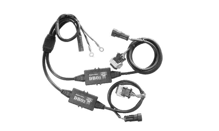


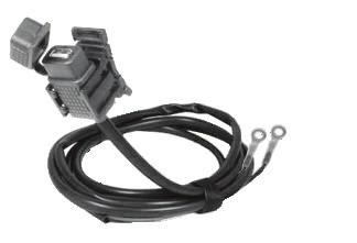


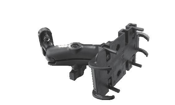

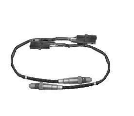

4 Product Overview SECTION 2 In the Box 3M 3M Motorcycle Vehicle Interface (MVI) USB cable for updating the MVI Velcro for fastening the MVI Zipties for fastening cables Motorcycle Sold Separately :) Optional Accessories (Sold Separately) Dual Wide-Band Oxygen (DBO2) Kit Mobile Handlebar Kit 4


5 Getting Started SECTION 3 Downloading the Update Software 1 Visit our 2 Highlight the Customer Support tab at the top of the web page. Select Download Product Update Software. 3 Click the Download button. 4 Select the Run button to start the installation process. NOTE: If you choose to Save the setup.exe file, you will need to locate the file you saved it to then double-click it to start the installation. 5


6 5 Click Next to view the License Agreement. 6 Read the License Agreement and check the I accept the terms in the license agreement if you agree. Then click Next. 7 Click the Change button if you would like to change the destination folder. Click Next to continue. 8 Click the Install button. 9 Click the Finish button to complete the installation. 6
. Each required field has an asterisk and must be filled in to continue.")


7 Updating the Motorcycle Vehicle Interface (MVI) 1 Double-Click the Superchips Update icon located on your computer. 2 Click the text Click Here To Register. The Registration Form will appear. 3 Fill out the required information on the Registration Form (not shown). Each required field has an asterisk and must be filled in to continue. NOTE: The User Name and Password you input will be used to log in as described below. 4 Click the Submit button. 5 Return to the Log In menu screen as shown above, and enter the User Name and Password you provided on the Registration Form. 6 Click the Login button and wait for the My Account menu to appear. 7 Connect the MVI to your computer using the supplied USB cable. Computer with Internet Connection USB Cable MVI CAUTION: The MVI s USB port should NEVER be connected to if the MVI is plugged into the Motorcycle. NOTE: Once the MVI is plugged into your PC, the server will check to see what updates are available for your device. If a software update is available, the MVI will automatically update. 8 Disconnect the MVI from the computer after the Update Software states that it is safe to do so. 7


8 Downloading the Vigilante Application (APP) Android Users 1 Open the Google Play Store App on your device. 2 Search for Superchips Vigilante and choose to download the software. NOTE: Once the Vigilante App has finished installing, it may be opened in Demo Mode without having to be paired with the MVI. ios Users 1 Open the App Store on your device. 2 Search for Superchips Vigilante and choose to download the software. NOTE: Once the Vigilante App has finished installing, it may be opened in Demo Mode without having to be paired with the MVI. Understanding the MVI LEDs NOTE: When connected to the motorcycle, the MVI will have two LEDs that become active. It is important to know how these LEDs are used to understand the state in which the MVI is currently in. Blue LED (Bluetooth) - Flashes when data is being sent over the Bluetooth connection. Red LED (Power) - Blinks when the device is powered on. 8


 6PIN (CAN) 4 Find a location for the MVI s plastic housing to be installed.")


9 Hardware Installation SECTION 4 1 Locate the Motorcycle s Data Port Socket. This socket will reside behind the battery side panel, or underneath the seat. 2 Remove the rubber plug from the Data port as shown. 3 Plug the MVI into the Data Port. NOTE: Depending on the year and model of the motorcycle, the Data Port will have either 4 or 6 pin locations. The pin count on the MVI will match the pin count on the motorcycle Data Port. 4PIN (J1850) 6PIN (CAN) 4 Find a location for the MVI s plastic housing to be installed. NOTE: For under-seat installs, the best option may be to tuck it in next to the frame. For side panel installations, use the velcro strip to fasten the plastic housing to a flat surface behind the panel. 5 Use the supplied zip-ties to fasten the cables away from moving and/or hot components. INSTALLATION TIPS - When routing the cables, avoid over-bending or kinking. If possible, route the cables along the existing motorcycle harness. - To avoid damage to the plastic housing and connectors, double check that they will not interfere with the seat. - If required, use the Velcro strap to fasten the enclosure to the motorcycle. Using a clean, dry rag, clean the areas the velcro will stick to. 9
 Wireless Bluetooth Connection The Display Device 1 On the")
 with your MVI). Android Devices ios Devices 2A Press the Bluetooth Settings Button. 2B Turn ON Bluetooth.")

10 Using Vigilante SECTION 5 NOTE: Before using Vigilante, make sure you have completed the following: - Update the MVI with the latest software - Install the MVI and other hardware on the motorcycle - Download the Vigilante App to your device - Pair the display device with the installed MVI Pairing Bluetooth MVI (Installed on Motorcycle) Wireless Bluetooth Connection The Display Device 1 On the motorcycle, turn the Ignition Switch to the Ignition position, and the engine Off/Run Switch to the Run position. 2 On the display device, open the Vigilante App. (A screen will appear letting you know that you have not yet made a connection ( Paired ) with your MVI). Android Devices ios Devices 2A Press the Bluetooth Settings Button. 2B Turn ON Bluetooth. 2C Click Scan for Devices. 2D Scroll down the list of devices and select the SC MVI ##### option. 2E Press the back arrow on the device to return to the App. 2A Click OK then open the device Settings. 2B Press the Bluetooth option. 2C Turn ON Bluetooth. 2D Scroll down the list of devices and select the SC MVI ##### option. 2E Return to the Vigilante App NOTE: Once the device is connected to the MVI, an icon will be visible. If the icon is blue, the device is connected to the MVI. If it is gray, it is not. 10

 PREFERENCES Allows you to adjust the unit of measure.")


11 The Main Menu - At a Glance ios Only: Swipe the screen to view the About & Settings. NOTE: For android devices, access the About and Settings menus by pressing the Menu button on the device. TUNING Program your motorcycle using pre-made tunes Search for tunes directly related to your hardware upgrades DTC SPY Display Diagnostic Trouble Codes (DTCs) Search for DTC information via the internet Clear DTCs from the ECM (Engine Control Module) PREFERENCES Allows you to adjust the unit of measure. Automatically save data logs. Calibrate the gear indicator. Change the brightness settings of the device. DAQ Monitor multiple PIDs at one time on multiple screens View the data using multiple types of graphic visualizations Record data logs DIGITAL DISPLAY Display and choose from multiple PIDs using digital style gauges Monitor 2,4,6,8, or 12 Gauges on one screen) DEVICE LIST (Android Only) Shows a list of MVIs your display device is currently paired with. GAUGES Display MPH, RPM, Engine Temp, and Battery Voltage PIDs on analog style gauges Monitor up to three different PIDs on one screen PERFORMANCE Test out your latest upgrades using the three available performance tests 0-60 mph 1/8 Mile 1/4 Mile ABOUT Gives you information related to the MVI as well as your motorcycle. 11


12 Understanding Parameter IDs (PIDs) NOTE: Before using Vigilante, it is important to understand what the term PID refers to. A PID is a code that the MVI uses to request specific data from the motorcycle. The MVI reads these codes while your device displays them. This gives you the ability to monitor any available PID in real time. There are two ways to display a PID. The DAQ Menu The DIGITAL DISPLAY Menu NOTE: After choosing one of the two options above, a screen with different PIDs being displayed will appear. In order to change what is being displayed, refer to the following steps. 1 Press and hold the gauge you would like to change. After a few seconds, the PID selection menu will appear. 2 Scroll through the list of available PIDs and choose one to view. FAVORITES Will only show the PIDs you have saved as a favorite. To Save a Favorite: 1 Press and hold the PID. 2 Choose the Add to Favorites option. RECENT Shows a list of PIDs that have been recently selected or modified. ALL PIDs Shows an alphabetical list of all available PIDs. 12


")


13 Display Options Analog Gauges These gauges will only show default PIDs, and cannot be modified. If you would like to monitor PIDs other than RPM, MPH, Battery Voltage, or Engine Temperature, please refer to the Digital Display section below. Digital Gauges These gauges are easy to read and can be modified to display different PIDs. Refer to the Understanding Parameter IDs section for information on how to change PIDs. Data Acquisition Gauges (DAQ) These gauges are similar to the other gauge options in that they allow you to monitor multiple PIDs on one screen. The DAQ feature goes one step further allowing you to monitor multiple PIDs on multiple screens. There are three DAQ screen types available NOTE: To change from one gauge screen to another, swipe the screen to the left/right. This will allow you to toggle between each of the available gauge layouts for any of the three gauge types. (i.e Digital, Analog, and DAQ) 13


14 Tuning NOTE: The Flash product comes pre loaded with one VIN-unlock credit. Meaning it can only tune one motorcycle. However, you can purchase a second credit if you would like to tune a second motorcycle. Once a second credit is available, two motorcycles each with three custom tunes (and one stock tune), can be stored on the MVI. 1 From the Main Menu, choose the Tuning Icon. NOTE: The four empty folders on the left indicate that the MVI is not currently storing any calibration files for your particular motorcycle. 2 Choose either Motorcycle 1 or Motorcycle 2. NOTE: Any calibrations previously stored in Motorcycle 1 or 2 for a different motorcycle will be erased and replaced. 3 Choose the Search Calibrations button at the bottom of the screen. 4 Login to your account with the User name and Password you specified during the registration process. NOTE: If you have not yet registered: Choose the Register button and follow the on-screen instructions. 5 Select an Exhaust Manufacturer, and an Intake Manufacturer from the list provided. NOTE: This choice will depend on what modifications you have made to your motorcycle. If the specific manufacturer is not available, choose Other. 14


15 6 Select a Model for both manufacturers. NOTE: If the exact model is not available, choose Other. Choosing Other will require you to choose a Style which will help narrow down the search. Choose the style that best describes your application. 7 Select the Next button. NOTE: The best match will be displayed. There may be other matches available for your specific application. If available, chose the Other Matches button to view them. 8 Select the Download button. NOTE: It is recommended that you be connected to a wireless network to minimize the data usage on your device. 9 Press the Program Calibration button. NOTE: If this is the first time programming a specific motorcycle, you will be asked if you would like to use a credit to program it. When you purchased the Vigilante Flash, you receive one free credit. This free credit allows you to connect and lock your MVI to one motorcycle. Once the free credit is spent, you have the choice to purchase a second credit giving the MVI the ability to lock onto and program a second Motorcycle. Only one credit per motorcycle is required. If you are out of credits, you will be prompted to visit our website at: 15


16 CAUTION: Do not turn the Ignition Switch or Run switch off during the programming process. Also, the MVI must remain plugged into the vehicles data port throughout the tuning process. Do not remove the cable from the data port while tuning. 10 After the motorcycle has been updated with the new calibration, turn the key to the off position for 20 seconds. Press OK. Vigilante Device Indicates that the motorcycle is currently programmed with the stored calibration file Motorcycle The original stock file is stored here and cannot be overwritten 16


17 DTC Spy DTCs (Diagnostic Trouble Codes) are used to diagnose problems with the motorcycle. Vigilante allows you to read and clear the DTCs. This screen also gives you the option to search the internet for more information on the currently selected code. Press the buttons located on the bottom of the screen to Clear and Search for DTCs. Performance Performance tests allow you to determine how your hardware upgrades and new tunes have affected your motorcycle s performance. WARNING - These tests are meant to be used in closed circuit racing environments only. Do not use these tests to break any traffic laws. Ignoring traffic laws could lead to injury or death. There are three tests to choose from: *0-60 mph - Time it takes to reach 60 mph from a stand still. *1/8 mile - Time it takes to travel 1/8 mile. *1/4 mile - Time it takes to travel 1/4 mile. To start and perform a test: 1 Choose the test you would like to perform. 2 Come to a complete stop. 3 Press the green Touch to Start button. 4 Watch the lights on the tree light up. When the green light is lit, GO!!! Once the test is completed, a TIME SLIP will be displayed showing the results of the test. 17


18 Recording Logs The Recorded Log is a history of raw data taken from the device based on start, and stop conditions specified by the user. Android Devices 1 Press the device s Menu button. 2 Choose Preferences from the menu. 3 Set the Start and End trigger values. 4 When logging is complete, plug the device into a computer via USB. 5 Enter the device folders and open the log file stored in Superchips\daq. ios Devices 1 On the Main Menu choose the Settings Icon. 2 Set the Start and End trigger values. 3 When logging is complete, plug the device into a computer with itunes. 4 Under the Apps tab in itunes, highlight the log file, and Save to a folder on the computer for viewing. NOTE: The Start trigger is the value at which the logs will start to record. The End trigger is the value at which the logging will stop. Calibrate Gear Indicator OTE: To properly calculate your gear indicator, he software needs both speed and RPM data points o determine what gear your motorcycle is currently n. The gear indicator will not be displayed until this alibration has been successfully completed. Android Devices 1 Press the Android device s menu button and choose the Preferences option. ios Devices 1 On the Main Menu choose the Settings Icon. Both Devices 2 Choose a Transmission type. 3 Press Calibrate Gear Indicator. 4 Start out in 1st gear and gradually accelerate. The display will ask you to HOLD. 5 Continue accelerating until you are instructed to SHIFT. Repeat this until all gears have been calibrated. Each gear will be shown WARNING - While driving, keep your eyes on the road! Use this feature only on safe, non congested roadways. Obey all traffic laws. Ignoring traffic laws could lead to injury or death. 18
19 Warranty WARRANTY INFORMATION This warranty gives you specific legal rights, and you may also have other rights which vary from state to state. LIMITED 1 YEAR WARRANTY Powerteq (hereafter SELLER ) gives Limited Warranty as to description, quality, merchantability, and fitness for any product s purpose, productiveness, or any other matter of SELLER s normal use* of the product sold herewith. The SELLER shall be in no way responsible for the product s open use and service and the BUYER hereby waives all rights other than those expressly written herein. This Warranty shall not be extended or varied except by a written instrument signed by SELLER and BUYER. The Warranty is Limited to one (1) year from the date of sale and limited solely to the parts contained within the product s kit. All products that are in question of Warranty must be returned shipping prepaid to the SELLER and must be accompanied by a dated proof of purchase receipt. All Warranty claims are subject to approval by the SELLER. Under no circumstances shall the SELLER be liable for any labor charged or travel time incurred in diagnosis for defects, removal, or reinstallation of this product, or any other contingent expenses. This shall constitute the sole remedy of the purchaser and the sole liability of the SELLER. To the extent permitted by law, the foregoing is exclusive and in lieu of all warranty and merchantability or fitness. In no event shall SELLER or its suppliers be liable for special or consequential damages. If the BUYER sends back a failed unit that is out of warranty and chooses to buy a refurbished unit, the refurbished unit will only carry a 90 day warranty. If the BUYER purchases a new unit at a predetermined discounted rate, it will have the standard 1 year warranty. Under no circumstances will the SELLER be liable for any damage or expenses incurred by reason of the use or sale of any such equipment. The installation of this product indicates that the buyer has read and understands this agreement and accepts its terms and conditions. In the event that the buyer does not agree with this agreement, the buyer may promptly return this product, in a new and unused condition, with a dated proof of purchase, to the place of purchase within thirty (30) days from date of purchase for a full refund. NOTE: This warranty is void for any new products purchased through auction web sites, classified listings, or publications. Warranty is valid only for new products purchased through Authorized Dealers (proof of purchase required for all warranty claims). *Intended normal use means this item is being used as originally intended and for the original application as sold by Powerteq. Any modifications to this item, or if it is used on an application other than as marketed, will VOID the warranty. It is the sole responsibility of the customer to determine that this item will work on the application they intend. Powerteq will accept no liability for custom applications. SECTION 6 19
20 Copyright 2012 REV 00 For additional questions not found in the user guide call: Technical Support (888) :00 am - 5:00 pm EST To expedite your support call, please have your Vehicle Information, Part Number, and Serial Number ready prior to calling Technical Support.
UNLEASH THE POWER. See More at: bullydog.com WITH BULLY DOG PERFORMANCE PRODUCTS. Doc.# BD43569 v1.0.1
 Bully Dog Technologies, LLC is a team built on integrity that is dedicated to leading the vehicle performance industry with an uncompromising code of ethics demonstrated in the soundness of its employees,
6.0L FORD Power Stroke
 6.0L FORD Power Stroke Exhaust Outlook Monitor Intake Modules OPERATING Instructions Thank You & Enjoy! For Free Technical Support Call (208) 397-3200 1 10 REMEMBER THIS IS A PERFORMANCE PRODUCT USE AT
R52 Top Commander. Installation and Configuration Guide. 325 Sharon Park Dr. #652. Menlo Park, CA USA (650)
") R52 Top Commander Installation and Configuration Guide 325 Sharon Park Dr. #652 Menlo Park, CA 94025 USA (650) 241-1161 www.fes-auto.com R52 Top Commander Installation Guide Page 2 Table of Contents Chapter
R52 Top Commander Installation and Configuration Guide 325 Sharon Park Dr. #652 Menlo Park, CA 94025 USA (650) 241-1161 www.fes-auto.com R52 Top Commander Installation Guide Page 2 Table of Contents Chapter
Micro Tuner Model RaceME Pro Common Rail Dodge Ram 6.7L, 24 Valve, Cummins Diesel Engine. Instruction Manual
 Micro Tuner Model RaceME Pro Common Rail Dodge Ram 6.7L, 24 Valve, Cummins Diesel Engine Instruction Manual PLEASE READ THIS ENTIRE INSTRUCTION MANUAL BEFORE PROCEEDING www.racemecanada.com Rev. 1.00A
Superchips 1705 MAX MicroTuner Ford Powerstroke 7.3L Turbo Diesel Vehicles Vehicle Programming Instructions
 Page 1 of 12 Form 0126K 10/26/2004 Superchips Inc. Superchips 1705 MAX MicroTuner Ford Powerstroke 7.3L Turbo Diesel Vehicles Vehicle Programming Instructions PLEASE READ THIS ENTIRE INSTRUCTION SHEET
Smarty Touch User Guide
 Smarty Touch User Guide Thank you for purchasing the Smarty Touch! We have put a lot of hard work into the production of this tuner, and we sincerely hope you enjoy it. This is a guide that explains most
Smarty. MADS - Micro Tuner model S-06 Common Rail Dodge Ram 5.9L, 24 Valve, Cummins Diesel Engine. Instruction manual
 Smarty - Micro Tuner model S-06 Common Rail Dodge Ram 5.9L, 24 Valve, Cummins Diesel Engine Instruction manual PLEASE READ THIS ENTIRE INSTRUCTION MANUAL BEFORE PROCEEDING www.madselectronics.com Page
GENUINE USB Cable set
 GENUINE USB Cable set Owner's Manual (Apple CarPlay / Android Auto mode) Thank you for purchasing a genuine Mazda accessory. Before use, be sure to thoroughly read these instructions. Please read the contents
QUICK START INSTALLATION GUIDE
 QUICK START INSTALLATION GUIDE !!!---WARNING---!!! FOR RACING VEHICLE USE ONLY Note: This product is not for use on roads or vehicles subject to emission control requirements and is not legal for use or
Lotus DX. sit-stand workstation. assembly and operation instructions. MODEL # s: LOTUS-DX-BLK LOTUS-DX-WHT
 Lotus DX assembly and operation instructions sit-stand workstation MODEL # s: LOTUS-DX-BLK LOTUS-DX-WHT safety warnings 13.6 Kg 30 lbs. 2.2 Kg 5 lbs. safety instructions/warning Read and follow all instructions
MSD Three Stage Delay Timer PN 7760
 MSD Three Stage Delay Timer PN 7760 ONLINE PRODUCT REGISTRATION: Register your MSD product online. Registering your product will help if there is ever a warranty issue with your product and helps the MSD
PIM-Mini Pulsed Current Source Operation Manual
 PIM-Mini Pulsed Current Source Operation Manual Directed Energy, Inc. 1609 Oakridge Dr., Suite 100, Fort Collins, CO 80525 (970) 493-1901 sales@ixyscolorado.com www.ixyscolorado.com Manual Document 7650-0007
MSD IGNITION FOR THE BOMBARDIER DS 650 QUAD PN /PN 4205
 MSD IGNITION FOR THE BOMBARDIER DS 650 QUAD PN 05-08-4205/PN 4205 Parts Included: 1 - PN 05-08-4205/PN 4205 Ignition WARNING: During installation, disconnect the battery cables. When Disconnecting, always
SMART SWITCH. User s Manual. This product is to be used with the MySmartBlinds automation kit.
 TM SMART SWITCH User s Manual This product is to be used with the MySmartBlinds automation kit. TABLE OF CONTENTS SAFETY INFORMATION 4 PARTS IDENTIFIER 6 ABOUT THE SMART SWITCH 6 INSTALLATION 7 PAIRING
In order to receive a user name, password and tunes, you must do the following 3 things:
 1 GETTING STARTED In order to receive a user name, password and tunes, you must do the following 3 things: 1. Fill out the disclaimer with all of your info and fax to 828-692-9968 or email it to sales@spartandieseltech.com.
P O W E R S U P P L Y M A N U A L
 POWER SUPPLY MANUAL Congratulations on the purchase of your new Corsair power supply. This User Agreement (the Agreement ) is a legal agreement between you ( You ), and Corsair Memory, Inc. ( Corsair ).
THECHARGEHUB.COM. User Manual. For Square & Round Models
 THECHARGEHUB.COM User Manual For Square & Round Models User Manual THECHARGEHUB.COM 7-Port USB Universal Charging Station Table of Contents General Safety Information...2 Care and Maintenance...3 Introduction...4
to your Pocket PC? 3. Click new to connect
 P i-geo+ USERS MANUAL How to connect your i-geo+ Version Issue date Description A 14 Nov. 2005 Initial Release Your Polstar i-geo+ GPS receiver uses world-class technology to provide you with a GPS receiver
User Guide. Subaru Turbo (North American Models)
") User Guide Subaru Turbo (North American Models) Page 2 Table of Contents Product Introduction 4 Supported Vehicle List 4 In-Box Contents 5 What Is A Map? 7 AccessPORT Installation 8 Pre-Installation 8
User Guide Subaru Turbo (North American Models) Page 2 Table of Contents Product Introduction 4 Supported Vehicle List 4 In-Box Contents 5 What Is A Map? 7 AccessPORT Installation 8 Pre-Installation 8
3.5 inch Hard Drive Enclosure. Model #: HDE350U. User s Manual
 3.5 inch Hard Drive Enclosure Model #: HDE350U User s Manual 2 Rev. 060811 User s Record: To provide quality customer service and technical support, it is suggested that you keep the following information
3.5 inch Hard Drive Enclosure. User s Manual
 3.5 inch Hard Drive Enclosure Model #: HDE355U User s Manual Rev. 060811 User s Record: To provide quality customer service and technical support, it is suggested that you keep the following information
MSD Enhancer Ignition for the Honda TRX400EX PN /PN 4203
 MSD Enhancer Ignition for the Honda TRX400EX PN 05-00-4203/PN 4203 Parts Included: 1 - Programmable Enhancer Ignition 1 - Y-Splice 1 - MSD Coil Assembly 1 - Black Ground Wire 1 - Ignition Mounting Brackets
TRF-ZW1 Z-Wave Extender. Owner s Manual
 TRF-ZW1 Z-Wave Extender Owner s Manual TRF-ZW1 Z-Wave Extender Owner's Manual 2014 Universal Remote Control, Inc. The information in this Owner s Manual is copyright protected. No part of this manual may
Honor Whistle Smart Control Rechargeable Headset User Guide
 Honor Whistle Smart Control Rechargeable Headset User Guide Box contents 1 x Headset 3 x Ear tips (small, medium and large) 1 x Ear hook Your headset at a glance 1 x USB adapter 1 x User guide 1 Charging
TrackCoach ProShift User Guide
 TrackCoach ProShift User Guide For Mini Cooper R50, R52, R53, R55 and R56 325 Sharon Park Blvd. #652 Menlo Park, CA 94025 (650) 241-1161 www.fes-auto.com TrackCoach ProShift User Guide Page 2 READ THIS!
Adjustable Timing Control PN 8680
 Adjustable Timing Control PN 8680 IMPORTANT: Read the instructions before attempting installation. Parts Included: 1 - Timing Control, PN 8680 1 - Control Knob 1-3/8" Bushing 1-2-Pin Weathertight Connector
MP3 Speaker USER GUIDE
 MP3 Speaker USER GUIDE Jazwares, Inc. 2012 CONTENTS Please read the instructions along with the Speaker carefully before you use it, so that you can operate it conveniently. WELCOME, Warnings & Safety
SERVICE BULLETIN DEPARTMENT OF COMPLIANCE VEHICLE SAFETY AND RECALL MANAGEMENT BUILDING N MAIN ST MIDDLEBURY, INDIANA
 SERVICE BULLETIN DEPARTMENT OF COMPLIANCE VEHICLE SAFETY AND RECALL MANAGEMENT BUILDING 11 423 N MAIN ST MIDDLEBURY, INDIANA 46540-9218 Technical Service Bulletin: 225-0754 O Integrity O Safety O Quality
DataPort 350 & 525 USB 2.0 and FireWire Enclosure User s Guide (800)
") DataPort 350 & 525 USB 2.0 and FireWire Enclosure User s Guide WWW.CRUINC.COM (800) 260-9800 TABLE OF CONTENTS PAGE Package Contents 1 Features and Requirements 2 Installation 6 Trouble Shooting 16 Technical
DataPort 350 & 525 USB 2.0 and FireWire Enclosure User s Guide WWW.CRUINC.COM (800) 260-9800 TABLE OF CONTENTS PAGE Package Contents 1 Features and Requirements 2 Installation 6 Trouble Shooting 16 Technical
MSD Advanced RPM Control Module PN 7761
 MSD Advanced RPM Control Module PN 7761 ONLINE PRODUCT REGISTRATION: Register your MSD product online and you ll be entered in our monthly 8.5mm Super Conductor Spark Plug Wire give-away! Registering your
GARMIN ELOG. Owner s Manual
 GARMIN ELOG Owner s Manual 2017 Garmin Ltd. or its subsidiaries All rights reserved. Under the copyright laws, this manual may not be copied, in whole or in part, without the written consent of Garmin.
Chapter 1 : FCC Radiation Norm...3. Chapter 2 : Package Contents...4. Chapter 3 : System Requirements...5. Chapter 4 : Hardware Description...
 Table of Contents Chapter 1 : FCC Radiation Norm...3 Chapter 2 : Package Contents...4 Chapter 3 : System Requirements...5 Chapter 4 : Hardware Description...6 Chapter 5 : Charging Your Keychain...7 Chapter
Woolich Racing. USB ECU Interface User Guide
 Woolich Racing USB ECU Interface User Guide 1) Introduction This user guide covers how to use the Woolich Racing USB ECU Interface. This includes: Connecting the USB ECU Interface into the Bike Harness
COOPER POWER SERIES. Input/Output (I/O) module installation instructions. Voltage Regulators MN225067EN
 module installation instructions. Voltage Regulators MN225067EN") Voltage Regulators MN225067EN Effective November 2016 Supersedes June 2014 (S225-70-13) COOPER POWER Input/Output (I/O) module installation instructions SERIES DISCLAIMER OF WARRANTIES AND LIMITATION OF
Voltage Regulators MN225067EN Effective November 2016 Supersedes June 2014 (S225-70-13) COOPER POWER Input/Output (I/O) module installation instructions SERIES DISCLAIMER OF WARRANTIES AND LIMITATION OF
Important Product & Information Guide
 Important Product & Information Guide Welcome to your new Climate FieldView Drive! Let us show you around. This guide shows you how your Climate FieldView Drive works, helps you set it up and gives you
!!!---WARNING---!!! 2011 DYNOJET RESEARCH ALL RIGHTS RESERVED FOR RACING VEHICLE USE ONLY
 !!!---WARNING---!!! FOR RACING VEHICLE USE ONLY Note: This product is not for use on roads or vehicles subject to emission control requirements and is not legal for use or installation on motor vehicles
PCM-7140 Pulsed Current Source Operation Manual
 PCM-7140 Pulsed Current Source Operation Manual Directed Energy, Inc. 1609 Oakridge Dr., Suite 100, Fort Collins, CO 80525 (970) 493-1901 sales@ixyscolorado.com www.ixyscolorado.com Manual Document 7650-0031
SP-C1 Mobile Docking Station Installation Guide
 SP-C1 Mobile Docking Station Installation Guide Box Contents After you unpack your SP-C1 Mobile Docking Station, make sure everything here is included: 1 x Docking Cradle 1 x Audio Cable 1 x Adhesive Mount
Chore-Tronics Mobile Server
 Chore-Tronics Mobile Server Installation & Operator s Instruction Manual Contact your nearby Chore-Time distributor or representative for additional parts and information. Chore-Time Group A division of
Adjustable Timing Control PN 8680
 Adjustable Timing Control PN 8680 ONLINE PRODUCT REGISTRATION: Register your MSD product online and you ll be entered in our monthly 8.5mm Super Conductor Spark Plug Wire give-away! Registering your product
EasyDiag Series. User s Manual (V ) Issued Date:
 Issued Date:") EasyDiag Series User s Manual (V1.00.001) Issued Date: 2014-08-15 Note: This user s manual applies to EasyDiag Series (EasyDiag and EasyDiag Plus) and is subject to change without prior written notice.
EasyDiag Series User s Manual (V1.00.001) Issued Date: 2014-08-15 Note: This user s manual applies to EasyDiag Series (EasyDiag and EasyDiag Plus) and is subject to change without prior written notice.
ASCL1 / ASCL2 CarLink Guide for Android Users
 ASCL1 / ASCL2 CarLink Guide for Android Users 2012 Audiovox Electronics Corporation. All rights reserved. CarLink Guide for Android Users New Account Creation After having CarLink installed, follow the
INSTALLATION INSTRUCTIONS
 THANK YOU FOR CHOOSING KURYAKYN! Protect yourself and others from possible injury and property damage or loss. Pay close attention to all instructions, warnings, cautions, and notices regarding the installation,
PowerRING Qi DUAL WIRELESS CHARGING RECEIVER
 PowerRING Qi DUAL WIRELESS CHARGING RECEIVER Please register online www.minibatt.com/register Qi-compatible USER MANUAL minibatt PowerRING.indd 1 25/4/16 12:42 Thank you for selecting minibatt products.
UÊ, Ê* - 1 Ê Ê Ê " /",Ê
 Instruction Manual VDV Distance Meter VDV501-089 ENGLISH Español pg. 6 Français pg. 12 User RG-6 Cat3 RG-11 Cat5e RG-59 Cat6 Short ft m Voltage! pf/ READY www.kleintools.com ENGLISH VDV Distance Meter
Olive_QS_SL.book Page 1 Wednesday, September 18, :41 PM Quick Start
 Quick Start NOTE: Features may vary by model and country. Setting up your tablet 1 2 3 After charging the battery, press and hold the power button for about 5 seconds until the HP logo is displayed. IMPORTANT:
Flying Magnet Crank Trigger Kit General Wiring
 Flying Magnet Crank Trigger Kit General Wiring ONLINE PRODUCT REGISTRATION: Register your MSD product online. Registering your product will help if there is ever a warranty issue with your product and
2.4GHz Wireless Optical Mouse
 2.4GHz Wireless Optical Mouse Model #: MP1950BLK User Manual PID #: 111587-109342 Rev. 140402 All brand name and trademarks are the property of their respective companies Mac and Mac OS X are registered
TOUCHBOX. iphone I N S T R U C T I O N M A N U A L
 TOUCHBOX W I R E L E S S C O N T R O L L E R iphone I N S T R U C T I O N M A N U A L Thank you for purchasing TouchBox by ZAETECH. Disclaimer TouchBox is for show and off road use only. It may not be
CubePro. Main PCB Replacement Guide. Prosumer 3D Printer. Original Instructions
 CubePro Prosumer 3D Printer Main PCB Replacement Guide Original Instructions 1 INTRODUCTION COPYRIGHT 2014 by All rights reserved. This document is subject to change without notice. This document is copyrighted
LITE TUNES #V
 LITE TUNES #V45000-71 Thank you for purchasing this new Sylvania LITE TUNES. This LITE TUNES assembles in minutes. The LITE TUNES: CARTON INCLUDES: 1 Litetunes 2 Remote controls 1 Set ground stake 1 Audio
StandUP WIRELESS CHARGER
 StandUP WIRELESS CHARGER Please register online www.minibatt.com/register Qi-compatible USER MANUAL minibatt StandUP.indd 1 25/4/16 12:21 Thank you for selecting minibatt products. Thank you for purchasing
DIGIT III Manual. Manual Version 1.3
 DIGIT III Manual The AirTurn DIGIT III is an 8-button rechargeable Bluetooth multi-function remote control. The DIGIT III works with most Bluetooth 4.0 tablets and computers, including PC, Mac, Android
Kanguru QSSD External SSD USB3.0 User Manual
 Copyright 2012, All Rights Reserved. Kanguru QSSD External SSD USB3.0 User Manual Notices and Information NOTICES AND INFORMATION Please be aware of the following points before using your Kanguru QSSD
DataPort 250 USB 2.0 Enclosure User s Guide (800)
") DataPort 250 USB 2.0 Enclosure User s Guide WWW.CRU-DATAPORT.COM (800) 260-9800 TABLE OF CONTENTS PAGE Package Contents 1 Features and Requirements 2 Installation 4 Trouble Shooting 13 Technical Support
DataPort 250 USB 2.0 Enclosure User s Guide WWW.CRU-DATAPORT.COM (800) 260-9800 TABLE OF CONTENTS PAGE Package Contents 1 Features and Requirements 2 Installation 4 Trouble Shooting 13 Technical Support
MEGA DIAL PANEL Instructions
 2036 Fillmore Street Davenport, Ia. 52804 563-324-1046 www.racedigitaldelay.com MEGA DIAL PANEL Instructions WARRANTY AND DISCLAIMER DIGITAL DELAY ELECTRONICS INC. WARRANTS THE PRODUCTS IT MANUFACTURES
COOP TENDER WI-FI OWNER S MANUAL
 Receive messages from your coop door. Monitor, control and configure your automatic chicken coop door from anywhere in the world with an Internet connection. COOP TENDER WI-FI OWNER S MANUAL 2015 Coop
BatteryCheck USER MANUAL BATTERY MANAGEMENT TECHNOLOGY THAT POWERS YOUR ADVENTURES.
 BatteryCheck USER MANUAL BM PRO - 19 Henderson Road, Knoxfield 3180, Victoria, Australia Phone +61 3 9763 0962 Fax +61 3 9763 8789 Email sales@teambmpro.com Web www.teambmpro.com BATTERY MANAGEMENT TECHNOLOGY
Bluetooth Cell/Smart-Phone/ GPS/Radar Integration Kit for Harley Ultra Driver Headset Position CFBR-HRUC
 Bluetooth Cell/Smart-Phone/ GPS/Radar Integration Kit for 1998-2012 Harley Ultra Driver Headset Position # 2012 J&M Corporation. All rights reserved. 5/12 Installation and Operation Instructions Installation
WCC100 IN-VEHICLE CHARGING CRADLE OWNER S MANUAL
 WCC100 IN-VEHICLE CHARGING CRADLE OWNER S MANUAL 128-9237B WCC100 In-Vehicle Charging Cradle 12 03 13.indd 1 12/4/2013 10:38:04 AM 128-9237B WCC100 In-Vehicle Charging Cradle 12 03 13.indd 2 12/4/2013
Bluetooth Cell/Smart-Phone/ GPS/Radar Integration Kit for Harley Ultra Driver Headset Position CGBH-HRUC
 2017 J&M Corporation. All rights reserved. 1/17 Bluetooth Cell/Smart-Phone/ GPS/Radar Integration Kit for 1998-2013 Harley Ultra Driver Headset Position # CGBH-HRUC Installation and Operation Instructions
ngauge Instruction Manual v1.10
 ngauge Instruction Manual v1.10 Table of Contents List of Revisions... 3 Important Notes... 4 Pre-Installation Notice... 5 1 Installation... 5 1.1 Cable Routing... 5 1.2 Attaching Windshield Mount... 5
Digital Keychain 1.4 LCD
 Digital Keychain 1.4 LCD Model #: 1-4DPF200 User s Manual PID # 161302-109241 Rev. 070731 All brand name and trademarks are the property of their respective owners USER S RECORD: To provide quality customer
USER S MANUAL. For 2.5 and 3.5 Models
 USER S MANUAL For 2.5 and 3.5 Models FCC COMPLIANCE STATEMENTS This equipment has been tested and found to comply with the limits for a Class B digital device, pursuant to Part 15 of the FCC Rules. These
Operating Bulletin MODBUS-RTU. The Fastest Flow Controller Company in the World!
 Operating Bulletin MODBUS-RTU The Fastest Flow Controller Company in the World! 1 Notice: Alicat Scientific, Inc. reserves the right to make any changes and improvements to the products described in this
EZ430-C9. Getting Started with Kionix EZ430-C9 Evaluation Board for the Texas Instruments MSP430 USB Stick Development Tool
 Getting Started with Kionix EZ430-C9 Evaluation Board EZ430-C9 Getting Started with Kionix EZ430-C9 Evaluation Board for the Texas Instruments MSP430 USB Stick Development Tool 36 Thornwood Dr. Ithaca,
Reference Guide VIB 10/11. (VIB 10 pictured) vehicle integration box
 vehicle integration box") VIB 10/11 Reference Guide (VIB 10 pictured) vehicle integration box 2006 2008 Garmin Ltd. or its subsidiaries Garmin International, Inc. Garmin (Europe) Ltd. 1200 East 151st Street, Liberty House Olathe,
VIB 10/11 Reference Guide (VIB 10 pictured) vehicle integration box 2006 2008 Garmin Ltd. or its subsidiaries Garmin International, Inc. Garmin (Europe) Ltd. 1200 East 151st Street, Liberty House Olathe,
Introduction...1. Package Contents... 1 Product Features... 1 Specifications Product Schematic...2. HDD Installation...3
 1 Table of Contents Introduction...1 Package Contents... 1 Product Features... 1 Specifications... 1 Product Schematic...2 HDD Installation...3 Connecting to your Computer...6 Connecting to Mac...7 Connecting
ASCL1 / ASCL2. CarLink Guide for BlackBerry Users Audiovox Electronics Corporation. All rights reserved.
 ASCL1 / ASCL2 CarLink Guide for BlackBerry Users 2012 Audiovox Electronics Corporation. All rights reserved. CarLink Guide for BlackBerry Users New Account Creation After having CarLink installed, follow
Super Stack. (Little Stack Wireless + Big Stack)
") Super Stack (Little Stack Wireless + Big Stack) EN Product Name: Little Stack Wireless Product type: Rechargeable power bank Model No: M8.C3.2Z/M9.C1.2Z/M10.C3.T10.3Z Ratings: Input: PIN 5V 1.6A / USB-C
Super Stack (Little Stack Wireless + Big Stack) EN Product Name: Little Stack Wireless Product type: Rechargeable power bank Model No: M8.C3.2Z/M9.C1.2Z/M10.C3.T10.3Z Ratings: Input: PIN 5V 1.6A / USB-C
R227. Terms Code Discount per Sales Code Qty Ordered AR-1227
 DSD Business Systems MAS 90/200 Enhancements R227 Terms Code Discount per Sales Code Qty Ordered AR-1227 Version 5.10 2 Terms Code Discount per Sales Code Qty Ordered Information in this document is subject
12/2013. Installation Guide & User Manual
 12/2013 Installation Guide & User Manual ABOUT THIS MANUAL This manual has been written to help you understand all the functions and capabilities of the Yamaha Snowmobile Diagnostic Tool in order to gain
Data Acquisition Instructions
 Page 1 of 26 Form DAQ2_A 01/23/2007 Superchips Inc. Superchips flashpaq Data Acquisition Instructions Visit Flashpaq.com for downloadable updates & upgrades to your existing tuner. Page 2 of 26 Form DAQ2_A
Table of Contents 3 Device layout 4 Charge device 7 Pair 9 Navigation 10 Customization 13 Status panel
 Quick Start Guide Table of Contents 3 Device layout 4 Charge device 7 Pair 9 Navigation 10 Customization 13 Status panel 14 Apps screen 15 Widgets 16 Notifications 17 Phone 20 Messages 23 S Health 25 Find
What s in the Box? REAR VIEW SAFETY
 TM 1 What s in the Box? 1 Full HD Color Infra-red Weather Proof Camera 1 Full HD 7" TFT LCD Color Monitor w/monitor Mount 1 Power Harness 1 66 Camera Cable 1 Power Connection Wire 1 Screw Kit for installation
(DH/D1) Dodge Ram 2500/3500 Pick Up Truck
 Dodge Ram 2500/3500 Pick Up Truck") Dealer Service Instructions for: Emissions Recall G30 Replace Oxygen Sensor Module and Reprogram ECM October 2007 Effective immediately all repairs on involved vehicles are to be performed according to
Dealer Service Instructions for: Emissions Recall G30 Replace Oxygen Sensor Module and Reprogram ECM October 2007 Effective immediately all repairs on involved vehicles are to be performed according to
DIGIT II Manual. The AirTurn DIGIT II is a 5-button Bluetooth rechargeable multifunction
 DIGIT II Manual The AirTurn DIGIT II is a 5-button Bluetooth rechargeable multifunction remote controller using the HID profile. The remote works with all known Bluetooth hosts that support HID including
MSD Programmable Launch RPM Controller
 MSD Programmable Launch RPM Controller PN 75611 Parts Supplied 1 - Programmable Launch Rev Limiter, PN 75611 4 - Self Tapping Screws 1 MSD Pro-Data+ Software 3.5 Disk 1 Deutsch Harness 1 9-Pin Computer
MANUFACTURING LLC Please read this manual carefully before using this product. 360SLT SMARTLINK TM TPMS TABLET USER MANUAL
 MANUFACTURING LLC Please read this manual carefully before using this product. 360SLT SMARTLINK TM TPMS TABLET USER MANUAL INDEX I. INTRODUCTION... 1 1. PACKAGE AND ACCESSORIES... 1 2. START TO USE...
INSTALLATION AND USER GUIDE 2800MWB SINGLE LINE BASIC FEATURE TELEPHONE
 INSTALLATION AND USER GUIDE 2800MWB SINGLE LINE BASIC FEATURE TELEPHONE TeleMatrix Copyright 2005 COMPLIANCE AND SAFETY As specified by FCC regulation, we are required to inform you of specific governmental
BTH-808 WIRELESS BLUETOOTH HEADSET USER S MANUAL
 BTH-808 WIRELESS BLUETOOTH HEADSET USER S MANUAL 1. INTRODUCTION The headset BTH-808 is the ultimate hands-free and wire-free solution that connects your mobile phones to your headset via Bluetooth radio
URC Light Sensor SEN-LITE for use with MRX units containing sensor ports
 URC Light Sensor SEN-LITE for use with MRX units containing sensor ports URC Light Sensor SEN-LITE 2014 Universal Remote Control, Inc. The information in this Owner s Manual is copyright protected. No
User Manual HDM-IPBX-003C. Smar t Controller for HDMI over IP series. rev: Made in Taiwan
 User Manual HDM-IPBX-003C Smar t Controller for HDMI over IP series rev: 170517 Made in Taiwan Safety and Notice The HDM-IPBX-003C Smart Controller for HDMI over IP series has been tested for conformance
User Guide SERIAL #:
 User Guide SERIAL #: Activation and Account Creation 1. Go to www.carlinkusa.com/activate/ 2. Enter your device s 12 digit Serial Number 3. Pick your service plan 4. Fill out the account and billing information
Messager USB w/ Night Answer
 Messager USB w/ Night Answer Digital Messaging System Installation & Users Guide Attention! Some USB drives have indicator LEDs - These LEDs may blink slow, fast, or may stay solid during playback. Any
nüvi for use with these nüvi models: 1300, 1310, 1340, 1350, 1370, 1390
 nüvi 1300 series quick start manual for use with these nüvi models: 1300, 1310, 1340, 1350, 1370, 1390 2009 Garmin Ltd. or its subsidiaries March 2009 190-01050-01 Rev. A Printed in Taiwan Looking at Your
MTX-A Temperature Gauge User Manual
 MTX-A Temperature Gauge User Manual 1. Installation... 2 1.1 Gauge Mounting... 2 1.2 Temperature Sensor Mounting... 2 1.2.1 Changing the MTX-A s Gauge Bezel... 2 1.3 Main Gauge Wiring... 3 1.3.1 Single
UNIDEN AUTOMOTIVE VIDEO RECORDER CAM 500
 UNIDEN AUTOMOTIVE VIDEO RECORDER CAM 500 IMPORTANT SAFETY INSTRUCTIONS This product is not waterproof. Do not expose it to rain or moisture. This product is intended for use in a motor vehicle. Don t install
Customer Service:
 TM www.turbolock.com Customer Service: 855-850-8031 Table of Contents Section 1 Information & Safety Warnings 4 1.1 Introduction 4 1.2 Safety Warnings 4 1.3 Disposal at End-of-Life 5 Section 2 Lock Functions
G2 Cradles. for ipod and iphone. Installation Guide/User manual
 G2 Cradles for ipod and iphone Installation Guide/User manual 2 Copyrights and Trademarks Copyright 2012 Audiovox Electronics Corporation The Audiovox and Audiovox Driven by DICE Electronics logos are
Remote Monitoring and Tracking for High Horsepower Systems. Operator s Manual. gplink.com. Operator s Manual Version 1.3
 Remote Monitoring and Tracking for High Horsepower Systems Operator s Manual Operator s Manual Version 1.3 gplink.com 1 Welcome Aboard Congratulations on the purchase of your gplink system. This operator
This guide describes features that are common to most models. Some features may not be available on your tablet.
 User Guide Copyright 2013 Hewlett-Packard Development Company, L.P. Bluetooth is a trademark owned by its proprietor and used by Hewlett-Packard Company under license. Google is a trademark of Google Inc.
MiniModules. Reference Manual. Series R CT 3002 V 1.0 MiniModule USB Service Adapter and Software
 Reference Manual R CT 3002 V 1.0 MiniModule USB Service Adapter and Software Series 3000 MiniModules LYNX Technik AG Brunnenweg 3 64331 Weiterstadt Germany www.lynx-technik.com Information in this document
Pro Mag A/Fuel Power Grid Controller PN 8772
 Pro Mag A/Fuel Power Grid Controller PN 8772 ONLINE PRODUCT REGISTRATION: Register your MSD product online. Registering your product will help if there is ever a warranty issue with your product and helps
INSTALLATION AND USER GUIDE 2800LBY SINGLE LINE HOTEL LOBBY TELEPHONE
 INSTALLATION AND USER GUIDE 2800LBY SINGLE LINE HOTEL LOBBY TELEPHONE TeleMatrix Copyright 2005 COMPLIANCE AND SAFETY As specified by FCC regulation, we are required to inform you of specific governmental
SafePace 600 Variable Messaging Sign
 SafePace 600 Variable Messaging Sign The new Traffic Logix SafePace 600 variable messaging sign is a versatile and full featured radar speed solution. Whether you want to simply alert drivers of their
CONNECTOR AND RECEPTACLE WIRE/CABLE ASSEMBLY INSTRUCTIONS
 CONNECTOR AND RECEPTACLE WIRE/CABLE ASSEMBLY INSTRUCTIONS Throughout this manual, look for this symbol. It means BE ALERT YOUR SAFETY IS INVOLVED. If you do not follow these safety instructions, personal
User Guide. Control Box. RoscoLED TM.
 RoscoLED TM Control Box User Guide This guide applies to the following RoscoLED Control Box models: RoscoLED Control Box 300W/Static White (293 22250 0000) RoscoLED Control Box 400W/VariWhite (293 22260
Messager USB by Nel-Tech Labs, Inc. Installation & User Manual
 Messager USB by Nel-Tech Labs, Inc. Installation & User Manual Index: Introduction... 3 Messager USB Layout Summary... Installation... Message Programming & Operation... Troubleshooting... 4 5 6 6 Warranty
Multi-Messager USB by Nel-Tech Labs, Inc. Installation & User Manual
 Multi-Messager USB by Nel-Tech Labs, Inc. Installation & User Manual Index: Introduction... 3 Multi-Messager USB Layout Summary... 4-5 Installation... 6-9 Message Programming & Operation... 10 Warranty