Hui Hu Department of Aerospace Engineering, Iowa State University Ames, Iowa 50011, U.S.A
|
|
|
- Shana Roberts
- 5 years ago
- Views:
Transcription
1 AerE 311L & AerE343L Lecture Notes Lecture # 13: Particle Image Velocimetry Technique Hui Hu Department of Aerospace Engineering, Iowa State University Ames, Iowa 50011, U.S.A
2 Particle-based Flow Diagnostic Techniques Seeded the flow with small particles (~ µm in size) Assumption: the particle tracers move with the same velocity as local flow velocity! Flow velocity V f = Particle velocity V p Measurement of particle velocity
, and assume the tracer particles")
 of the tracer particles between known")


3 Particle-based techniques: Particle Image Velocimetry (PIV) To seed fluid flows with small tracer particles (~µm), and assume the tracer particles moving with the same velocity as the low fluid flows. To measure the displacements (ΔL) of the tracer particles between known time interval (Δt). The local velocity of fluid flow is calculated by U= Δ L/Δt. ΔL t= t 0 +Δt t=t 0 ΔL U = Δ t spanwise vorticity (1/s) m/s Y (mm) 20 0 GA(W)-1 airfoil shadow region -60 A. t=t 0 B. t=t μs C. Derived Velocity field X (mm)
4 PIV System Setup Particle tracers: Illumination system: Camera: Synchronizer: Host computer: to track the fluid movement. to illuminate the flow field in the interest region. to capture the images of the particle tracers. the control the timing of the laser illumination and camera acquisition. to store the particle images and conduct image processing. seed flow with tracer particles Illumination system (Laser and optics) camera Synchronizer Host computer


5 Tracer Particles for PIV Tracer particles should be neutrally buoyant and small enough to follow the flow perfectly. Tracer particles should be big enough to scatter the illumination lights efficiently. The scattering efficiency of trace particles also strongly depends on the ratio of the refractive index of the particles to that of the fluid. For example: the refractive index of water is considerably larger than that of air. The scattering of particles in air is at least one order of magnitude more efficient than particles of the same size in water. hν Incident light Scattering light. d=1μm b. d=10μm c. d=30μm
6 Tracer Particles for PIV A primary source of measurement error is the influence of gravitational forces when the density of the tracer particles is different to the density of work fluid. 2 ( ρ p ρ) U g = d p g 18μ The velocity lag of a particle in a continuously acceleration fluid will be: r r r 2 ( ρ p ρ) U s = U P U = d p g 18μ r r t U p ( t) = U (1 exp( ); τ s 2 ρ p τ s = d p 18μ U r U r P
7 Tracers for PIV measurements in liquids (water): Polymer particles (d=10~100 μm, density = 1.03 ~ 1.05 kg/cm 3 ) Silver-covered hollow glass beams (d =1 ~10 μm, density = 1.03 ~ 1.05 kg/cm3) Fluorescent particle for micro flow (d=200~1000 nm, density = 1.03 ~ 1.05 kg/cm3). Quantum dots (d= 2 ~ 10 nm) Tracer Particles for PIV Tracers for PIV measurements in gaseous flows: Smoke Droplets, mist, vapor Condensations. Hollow silica particles (0.5 ~ 2 μm in diameter and 0.2 g/cm3 in density for PIV measurements in combustion applications. Nanoparticles of combustion products
8 illumination system The illumination system of PIV is always composed of light source e and optics. Lasers: : such as Argon-ion laser and Nd:YAG Laser, are widely used as light source in PIV systems due to their ability to emit monochromatic light with high energy density which can easily be bundled into thin light sheet for illuminating ing and recording the tracer particles without chromatic aberrations. Optics: : always consisted by a set of cylindrical lenses and mirrors to shape the light source beam into a planar sheet to illuminate the flow field. Laser beam Laser sheet laser optics

9 Double-pulsed Nd:Yag Laser for PIV
10 Optics for PIV
11 Cameras The widely used cameras for PIV: Photographic film-based cameras or Charged-Coupled Coupled Device (CCD) cameras. Advantages of CCD cameras: It is fully digitized Various digital techniques can be implemented for PIV image processing. Conventional auto- or cross- correlation techniques combined with special framing techniques can be used to measure higher velocities. Disadvantages of CCD cameras: Low temporal resolution (defined by the video framing rate): Low spatial resolution:
 with frame rate of f=30hz. Used by U.S., Canada, Mexico, some parts of Central and South Old field America, Japan, Taiwan, and Korea.")
12 Interlaced Cameras The fastest response time of human being for images is about ~ 15Hz Video format: PAL (Phase Alternating Line ) format with frame rate of f=25hz (sometimes in 50Hz). Used by U.K., Germany, Spain, Portugal, Italy, China, India, most of Africa, and the Middle East NTSC format: established by National Television Standards Committee (NTSC) with frame rate of f=30hz. Used by U.S., Canada, Mexico, some parts of Central and South Old field America, Japan, Taiwan, and Korea. 1 frame (1,3,5 639) F=30Hz Even field (2,4,6 640) 640) Odd field Even field 16.6ms 16.6ms time 480 pixels by 640 pixels Interlaced camera


13 Progressive scan camera All image systems produce a clear image of the background Jagged edges from motion with interlaced scan Motion blur caused by the lack of resolution in the 2CIF sample 1st frame Only progressive scan makes it possible to identify the driver Exp=33.33ms 2nd frame exp=33.33ms

14 Function of Synchronizer: Synchronizer To control the timing of the laser illumination and camera acquisition To laser To camera 1st pulsed 2nd pulsed Synchronizer From computer Timing of pulsed laser Δt 1 st frame exposure 33.33ms (30Hz) Timing of CCD camera 2nd frame exposure time
15 Host computer To send timing control parameter to synchronizer. To store the particle images and conduct image processing. Image data from camera Host computer To synchronizer


16 Single-frame technique V L=V*Δt particle Streak line single-pulse Multiple-pulse pulse Particle streak velocimetry


17 Multi-frame technique a. T=t 0 b. T=t 1 c. T=t 2 a. T=t 3 ΔL t= t 0 +Δt t=t 0 ΔL U = Δ t
18 Image Processing for PIV To extract velocity information from particle images. Image processing t=t0 t=t0+4ms A typical PIV raw image pair Y/D X/D Velocity U/U in


19 Particle Tracking Velocimetry (PTV) 1. Find position of the particles at each images 2. Find corresponding particle image pair in the different image frame 3. Find the displacements between the particle pairs. 4. Velocity of particle equates the displacement divided by the time interval between the frames. t=t 0 t=t 0 +Δt Low particle-image density case
-2 1.")


20 Particle Tracking Velocimetry (PTV)-2 1. Find position of the particles at each images 2. Find corresponding particle image pair in the different image frame 3. Find the displacements between the particle pairs. 4. Velocity of particle equates the displacement divided by the time interval between the frames. Search region for time step t=t 3 Search region for time step t=t 4 Search region for time step t=t 2 Particle position of time step t=t 1 Four-frame frame-particle tracking algorithm PTV results
21 Correlation-based PIV methods t=t 0 t=t 0 +Δt Corresponding flow high particle-image density velocity field
22 Correlation-based PIV methods Searching window size (SB) SB SA SA Interrogation window SB q(x,y) P(x,y) SB t=t 0 t=t 0 +Δt Correlation coefficient function R ( p, q) = ( f ( x, y) f )( g( x, y) g) dv ( f ( x, y) f ) 2 dv ( g( x, y) g) 2 dv


23 Cross Correlation Operation Signal A: Signal B: R ( u) = [ f ( x)* g( x + u)] dx [ f ( x) 2 ] dx* [ g( x + u) 2 ] dx
24 Correlation coefficient distribution R(p,q) Peak location S1 S10 S19 S28 R ( p, q) = ( f ( x, y) f )( g( x, y) g) dv ( f ( x, y) f ) 2 dv ( g( x, y) g) 2 dv


25 Comparison between PIV and PTV Particle Tracking Velocimetry: Tracking individual particle Limited to low particle image density case Velocity vector at random points where tracer particles exist. Spatial resolution of PTV results is usually limited by the number of the tracer particles Correlation-based PIV: Tracking a group of particles Applicable to high particle image density case Spatial resolution of PIV results is usually limited by the size of the interrogation window size Velocity vector can be at regular grid points. PTV t=t 0 +Δt PIV 5 Copyright by Dr. Hui Iowa State University. All 1 Rights Reserved! X/D Velocity U/U in Y/D
26 Estimation of differential quantities 20 Y (mm) X (mm)

27 Estimation of differential quantities


28 Estimation of Vorticity distribution ϖ z = V x U y
29 Stokes Theorem: r r v r Γ = V dl = ϖ da C S Estimation of Vorticity distribution ϖ z = Γx y da
30 Y mm Vorticity distribution Examples 200 Spanwise Vorticity ( Z-direction ) spanwise vorticity (1/s) m/s water free surface Re =6,700 Uin = 0.33 m/s Y(mm) GA(W)-1 airfoil 0 X mm Uout shadow region X (mm)
31 Ensemble-averaged quantities Mean velocity components in x, y directions: U = N i= 1 u i / N V = v i / N N i= 1 Turbulent velocity fluctuations: N 2 u' = ( ui U ) / N v' = ( v i V ) i= 1 N i= 1 2 Turbulent Kinetic energy distribution: TKE = ρ ( u' + v' 2 ) Reynolds stress distribution: τ = ρu' v' = ρ N i= 1 ( u i U )( v N i U )
32 Ensemble-averaged quantities 10 m/s 60 vort: m/s 60 U m/s: Y (mm) 0 GA(W)-1 airfoil Y (mm) 0 GA(W)-1 airfoil shadow region -40 shadow region X (mm) X (mm) T.K.E Normalized 60 Reynolds Stress Y (mm) 20 0 GA(W)-1 airfoil Y (mm) 20 0 GA(W)-1 airfoil shadow region -40 shadow region X (mm) X (mm)

 ( 1 2 2 2 2 2 2 2 2 y v x v y p y v v x v u y u x u")
33 Copyright by Dr. Hui Iowa State University. All Rights Reserved! Pressure field estimation Pressure field estimation ) ( 1 ) ( y v x v y p y v v x v u y u x u x p y u v x u u + + = = + ρ μ ρ ρ μ ρ
34 Integral Force estimation t C. V. r ρv dv + C. S. r r r ~ r r ( ρv V ) da = P da + ρ f C. S. C. V. dv r + F 10 m/s 60 U m/s: Y(mm) 0 GA(W)-1 airfoil shadow region X (mm)
35 AerE 545 class notes #34 Microscopic Particle Image Velocimetry technique Part - 2 Hui Hu Department of Aerospace Engineering, Iowa State University Ames, Iowa 50011, U.S.A
36 System Setup of a conventional PIV system Particle tracers: Illumination system: Camera: Synchronizer: Host computer: to track the fluid movement. to illuminate the flow field in the interest region. to capture the images of the particle tracers. the control the timing of the laser illumination and camera acquisition. to store the particle images and conduct image processing. seed flow with tracer particles Illumination system (Laser and optics) camera Synchronizer Host computer
 Nd:YAG Laser l = 532 nm Beam Expander Epi-fluorescent Prism / Filter Cube l = 560 nm Lens 1030 x 1300 x 12 bit")
37 System Setup of a Typical Micro- PIV system Microfluidic device Microscope Lens (NA=1.4, 60x) Nd:YAG Laser l = 532 nm Beam Expander Epi-fluorescent Prism / Filter Cube l = 560 nm Lens 1030 x 1300 x 12 bit Interline Transfer Cooled CCD Camera

38 Differences between conventional PIV and μ-piv Particle tracers: Conventional PIV: Tracer particle size is about ~1 μm for gaseous flows and ~ 10 μm for liquid flows To detect scattering light signal Micro-PIV: Coated fluorescent particles. Particle size is much smaller 200 nm ~1000 nm for liquid flows To detect fluorescent light signal Spectral Properties of Standard Fluorescent Microspheres : Color Excitation Maxima (nm) Emission Maxima (nm) Stokes Shift (nm) Green 469 (blue) 509 (green) 40 Red 541 (green) 365 (UV) 611 (red) 446 (blue) Blue 388 (UV-violet) 412 (violet) 446 (blue) 473 (blue) 58 61
39 Diameter of Particle Images for Micro-PIV Diffraction-limited spot size: Effective size of the tracer particles:
40 Out-of of-plane Spatial Resolution for Micro-PIV Conventional Macro -PIV measurements: The light sheet illuminates only particles contained within the depth of focus of the recording lens, providing high quality in-focus particle images to be recorded with low levels of background noise being emitted from the out-of of-focus focus particles. The out-of of-plane spatial resolution of the velocity measurements is defined clearly by the thickness of the illuminating light sheet. Micro-PIV measurements: Due to the small length scales associated with μ-piv, it is difficult if not impossible to form a light sheet that is only a few microns thick, and even more difficult to align a light sheet with the object plane of an objective lens. It is common practice in μ-piv to illuminate the test section with a volume of light, and rely on the depth of field of the lens to define the out-of of-plane thickness of the measurement plane.

41 Out-of of-plane Spatial Resolution for Micro-PIV A typical Micro-PIV image
42 Visibility of Particles tracers For a given set of recording optics, particle visibility can be increased : By decreasing particle concentration, C, By decreasing test section thickness, L. For a fixed particle concentration, the visibility can be increased by By decreasing the particle diameter, By increasing the numerical aperture of the recording lens. Visibility depends only weakly on magnification, and object distance, so.
43 Effect of Brownian Motion on micro-piv measurements Particle response time: For 300 nm diameter polystyrene latex spheres immersed in water, the particle response time is ~10-9 s. Brownian motion is the random thermal motion of a particle suspended in a fluid. The motion results from collisions between fluid molecules and suspended particles. The velocity spectrum of a particle due to Brownian motion consists of frequencies too high to be resolved fully and is commonly modeled as Gaussian white noise. A quantity more readily characterized is the particle s s average displacement after many velocity fluctuations. For time intervals Δt much larger than the particle inertial response time, the dynamics of Brownian motion are independent of inertial parameters such as particle and fluid density. The mean square distance of diffusion is proportional to DΔt, where D is the diffusion coefficient of the particle. For a spherical particle subject to Stokes drag law, the diffusion coefficient D was first given by Einstein (1905) as: where d p is the particle diameter, κ is Boltzmann's constant, T is the absolute temperature of the fluid, and μ is the dynamic viscosity of the fluid.
44 Effect of Brownian Motion on micro-piv measurements The errors estimated by above Equations show that the relative Brownian intensity error decreases as the time of measurement increases. Larger time intervals produce flow displacements proportional to Δt while the root mean square of the Brownian particle displacements grow as Δt 1/2. In practice, Brownian motion is an important consideration when tracing 50 to 500 nm particles in flow field experiments with flow velocities of less than about 1 mm/s. For a velocity on the order of 0.5 mm/s and a 500 nm seed particle, the lower limit for the time spacing is approximately 100 μs for a 20% error due to Brownian motion. This error can be reduced by both averaging over several particles in a single interrogation spot and by ensemble averaging over several realizations. The diffusive uncertainty decreases as 1/ N, where N is the total number of particles in the average
 is generally acknowledged to be the first modern scientist who recorded evidence of particle migration with his observations that blood cells flowing through capillaries tended to")
45 Saffman effect Particles are found to intend to stay away from the regimes with high velocity gradient. Poiseuille (1836) is generally acknowledged to be the first modern scientist who recorded evidence of particle migration with his observations that blood cells flowing through capillaries tended to stay away from the walls of the capillaries. Taylor (1955) scanned the cross-section section of a tube carrying a suspension and noticed areas of reduced cell concentration not only near the walls, but also near the center of the channel. Segré and Silberberg (1962) systematically performed experiments that confirmed both observations migration away from the walls and migration away from the center of the channel and determined that migration rate was proportional to the square of the mean velocity in the channel as well as the fourth power of the particle radius. Saffman (1965) analytically considered the case of a rigid sphere translating in a linear unbounded shear field. G : velocity gradient Vs : is slip velocity Vm: : migration velocity
46 Micro-PIV setup

47 Correlation averaging method instantaneous PIV image pair Instantaneous Correlation coefficient distribution Find peak and sub-pixel interpolation instantaneous Velocity vectors averaging processing Conventional method: Averaged Velocity vectors instantaneous PIV Instantaneous image pair Correlation coefficient distribution Correlation averaging method Correlation averaging method: averaging processing Averaged correlation coefficient distribution Find peak and sub-pixel interpolation Averaged Velocity vectors

48 Near Wall Flow Measurement Using Micro-PIV


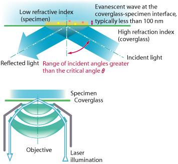
49 Total Internal Reflection sinϕ1 n2 = sinϕ2 n1 n1 > n2 ϕ2 > ϕ1 ϕ = π / 2 ϕ 2max 1cri sin 1 TIR occurs when n 2 < n 1 and θ i > θ c = ( n 2 / n 1 )


50 Nano-PIV

51 Nano-PIV C. M. Zettner.. and M. Yoda, Experiments in Fluids (2002)


")


52 A Study of Insulin Occlusion Using Insulin Pump Flexible tubing (I.D. 356μm) microchannel Host computer Insulin pump Objective lens Beaker optics Dichroic mirror Digital delay generator Nd:Yag Laser Emitter filter CCD camera Mirror (SensiCam)
 3 2 1 0 Y (mm) 0.2-1 0 20 40 60 80 100 120 140 160 180 200 0.")
53 Micro-PIV Measurement Results 300μm Velocity (mm/s) Channel Wall Microchannel centerline velcoity (mm/s) Y (mm) Time (s) 0 Channel Wall X (mm)

54 Micro-PIV Measurement Results Y(mm) Velocity (mm/s) Channel Wall Channel Wall X(mm)
55 Objectives_template Module 3: Velocity Measurement Lecture 12: Introduction to PIV The Lecture Contains: Particle image velocimetry Apparatus and Instrumentation Experimental Setup Test Cell Particle Image Velocimetry Seeding Arrangement for PIV Particle Dynamics Generating a Light Sheet Synchronizer file:///g /optical_measurement/lecture12/12_1.htm[5/7/ :58:12 AM]
56 Objectives_template Module 3: Velocity Measurement Lecture 11: Particle image velocimetry The method relies on the fact that small particles introduced in a fluid stream would move with the local fluid velocity. These particles, ideally, are neutrally buoyant with respect to the fluid medium and would not respond to buoyancy forces. This is particulalrly true for particles of very small diameters where surface forces (that scale with the square of the particle diameter) are much larger than body forces (that scale as diameter cube). The basic measurements in particle image velocimetry (PIV) relate particle displacement over a time period in such a way that velocity is measured as the ratio of displacement and the time interval. The former being a vector, velocity components in the plane of illumination are jointly determined. Since particle sizes are very small, a small interrogation area selected by the camera for determination for velocity would have several particles. These, in turn, are indistinguishable. The displacement measured is a statistical quantity, applicable for the collection of particles as a whole. The local velocity thus obtained is a group velocity of these particles. Statistical methods preferred are usually based on cross-correlation between a pair of images that are separated by a time interval of. Clearly, smaller the time interval, better is the time estimate of velocity. Intervals as small as a few hundred nanoseconds are possible with pulsed lasers; conventional light sources severely fail in this regard. It should also be clear that the cameras used for imaging should record two images of the particle positions separated on the time axis by such a small interval. The important components of a PIV system would then be (a) a pulsed light source, (b) an imaging system synchronized with the laser, (c) seeding arrangement for creating particles, and (d) software for calculating the cross-correlation function between the image pairs. The details of a simple PIV system are presented the following sections. file:///g /optical_measurement/lecture12/12_2.htm[5/7/ :58:13 AM]
57 Objectives_template Module 3: Velocity Measurement Lecture 11: Apparatus and Instrumentation A setup for conducting experiments where wake properties of a square cylinder can be studied has been constructed in the laboratory. The setup resembles a low speed wind tunnel, though smaller in the overall size. It is a vertical test cell made of Plexiglas with two optical windows, one for laser sheet and the other for recording images by the CCD camera. The working fluid is air and the direction of overall fluid motion is in the vertically upward direction. Particle Image Velocimetry (PIV) and Hotwire Anemometry (HWA) have been primarily used for velocity measurements. Flow visualization study has been carried out at low seeding density in the PIV setup. The cylinder is oscillated with the help of an electromagnetic actuator. This module describes details of the experimental hardware, including instruments and auxiliary equipment used in the present study. The validation results for proper PIV technique implementation, flow parallelism and turbulence intensity of the test cell and the effect of end plates have been discussed. file:///g /optical_measurement/lecture12/12_3.htm[5/7/ :58:13 AM]
58 Objectives_template Module 3: Velocity Measurement Lecture 12: Introduction to PIV Experimental Setup A schematic drawing of the experimental setup is shown in Figure 3.8. It comprises the following components: flow circuit, traversing mechanism for hotwire measurements, laser (pulsed), CCD camera, seeding arrangement for PIV measurements, and data acquisition system. The free-stream velocity approaching the cylinder has been determined using a pitot-static tube connected to a micromanometer. The micro-manometer has a resolution of 0:001 mm of it translates to an error in Reynolds number of about The details of the test cell are discussed here and the PIV and HWA techniques are presented in the following section. Fig 3.8: Schematic of the experimental setup file:///g /optical_measurement/lecture12/12_4.htm[5/7/ :58:13 AM]
 is with an overall length of 2 m.")
59 Objectives_template Module 3: Velocity Measurement Lecture 12: Introduction to PIV Test cell Experiments have been performed in a vertical open-loop airflow system. The crosssection of the active portion of the test cell (to be called the test section) is with an overall length of 2 m. The active length of the test section where wake measurements have been carried out is 0:3 m. A contraction ratio of 10:1 ahead of the test section has been used. Prisms of square cross-section (3-4 mm edge) have been used for experiments as square cylinders. They are made either of Plexiglas or brass and carefully machined for sharp edges. Each cylinder is mounted horizontally with its axis perpendicular to the flow direction. It is supported along the two side walls for fixed cylinder experiments and mounted on actuators for oscillating cylinder experiments. Fig 3.9: Picture of the PIV setup used for the present experiments Two different ratios (also called aspect ratios) of 16 and 28 have been utilized in the experiments. The two aspect ratios were realized depending on the alignment of the cylinder axis with respect to test section. The corresponding blockage ratios are 0:03 and 0:06 respectively. With reference to Figure 3.8.the - axis is vertical and aligned with the mean flow direction. The - axis coincides with the cylinder axis and the - axis is perpendicular to both and. file:///g /optical_measurement/lecture12/12_5.htm[5/7/ :58:13 AM]

60 Objectives_template Module 3: Velocity Measurement Lecture 12: Introduction to PIV Flow in the test section was set up by a small fan driven by a single phase motor. The suction side of the fan was used to draw the flow from the test cell. The power supply to the blower was from an online uninterrupted power supply unit to ensure practically constant input voltage to the motor. For better control of the voltage setting, particularly at low fan RPM and hence at low flow rates, the output of the UPS was stepped down via two variacs connected in series. In turn, this had the effect of minimizing the velocity fluctuations in the approach flow. The free stream turbulence level in the approach flow was quite small and it was found to be less than the background noise of the anemometer ( %). Flow parallelism in the approach ow was better than over of the width of the test cell. The validation of the test cell is discussed in a later section of the present module. Fig 3.10: PIV components: (a) CCD Camera (b) Nd-YAG laser (c) Synchronizer file:///g /optical_measurement/lecture12/12_6.htm[5/7/ :58:14 AM]
61 Objectives_template Module 3: Velocity Measurement Lecture 12: Introduction to PIV The flow to the test cell goes through three parts, namely the settling chamber, a honeycomb section and a contraction cone. Fine screens are mounted in the settling chamber for reducing the turbulence}. level of flow entering the test section. The contraction ratio of the contraction cone in area units is 10:1. The contraction cone reduces the spatial irregularities in the velocity distribution and helps in the decay of turbulence intensity by proper stretching of the vortices. The function of the honeycomb is to straighten the flow by damping the transverse components of velocity, and to reduce the turbulence level by suppressing the turbulence scales that are larger than the size of a honeycomb cell. The screens are used to suppress the small disturbances generated at the outlet tips of the honey comb. Proper mesh size gradation has been utilized by examining the diameter of the elements of the honeycomb, and hence the length scale of the vortices generated. Specially, two screens, one with a coarse grid (10 per cm 2 ) and the other with a fine grid (100 per cm 2 ) have been used in the test cell. Fig 3.11: Imaging system for PIV file:///g /optical_measurement/lecture12/12_7.htm[5/7/ :58:14 AM]
62 Objectives_template Module 3: Velocity Measurement Lecture 12: Introduction to PIV Contd... The distance maintained between the mesh and honeycomb has been selected by trial and error, to ensure that the smoothest possible flow approaches the square cylinder. Stable velocities in the range of 0:5 3 m/s could realized in the test section. These values correspond to a Reynolds number range of for the cylinder sizes referred earlier. A seeding arrangement is fitted prior to the honeycomb for PIV measurements. file:///g /optical_measurement/lecture12/12_8.htm[5/7/ :58:14 AM]
63 Objectives_template Module 3: Velocity Measurement Lecture 12: Introduction to PIV Particle Image Velocimetry Traditionally, quantitative measurements of fluid velocity have been carried out using a pitot-static tube and hotwire anemometry. Both these techniques require insertion of a physical probe into the flow domain. This process is intrusive and can alter the flow field itself. In addition, measurements are averages over a small representative volume. The probe has to be physically displaced to various locations to scan the entire region of interest. The development of cost-effective lasers led to the development of Laser Doppler velocimeter (LDV) that uses a laser probe to enable non-intrusive velocity measurements. Velocity information by LDV however, is obtained point-wise similar to that of the pitot-static tube and the hotwire probe. Particle image velocimetry (PIV) is the state-of -the-art technique for velocity measurement in experimental fluid mechanics. Original contributions towards its development were made by Adrian (1991), Gharib (1991), Melling (1997), and Westerweel (1997). The most important advantage of PIV is that it is a non-intrusive technique and gives the spatial details of the flow field over a plane of interest. There is some flexibility in the choice of the measuring plane. The measurement process can be repeated in time to yield temporal evolution of the flow field. The ability to make global velocity measurements makes PIV a special tool in experimental fluid mechanics.with PIV, it is possible to acquire practically instantaneous velocity fields with high spatial resolution. The spatial resolution is limited by the thickness of the laser sheet and the choice of the interrogation spot during analysis. The latter is about 8 or 16 pixels. The smallest length scale that can be detected depends on the size of the pixel, and hence the spatial resolution of the camera. Depending on the camera speed, a time series of images can be recorded during experiments. The ensemble average of the instantaneous velocity vectors yields the time-averaged velocity field. This includes zones of reversed flow that cannot be dealt with by hotwire and pitot probes. Once the velocity field is obtained, other quantities such as vorticity, strain rates and momentum fluxes can be estimated. With developments in lasers, camera and high speed/low cost computers it is now possible to use PIV regularly for research and industrial applications. file:///g /optical_measurement/lecture12/12_9.htm[5/7/ :58:15 AM]
64 Objectives_template Module 3: Velocity Measurement Lecture 12: Introduction to PIV The picture of the PIV setup is shown in Figure 3.9 and the photograph of important hardware of PIV is shown in Figure In the present experiments, PIV measurements were carried out at selected planes perpendicular and parallel to the cylinder axis. A double pulsed Nd:YAG laser of wavelength and with a maximum repetition rate of per laser head was used. The light sheet had a maximum scan area of The sheet thickness was about 1 mm to minimize the effect of the out-of-plane velocity component. The assembly of Peltier-cooled 12 bit CCD camera and frame grabber with a frame speed of was used for acquisition of PIV images. Figure 3.11 shows geometric diagram of PIV measurements. A cross section of the flow is illuminated with a thin light sheet, and the tracer particles in the light sheet are projected onto a recording medium (CCD) in the image plane of a lens as shown in Figure 3.11.The intensity of the light sheet thickness is assumed to changes only in the direction. The magnification of particle image depends upon the position of the imaging lens. The CCD consisted of an array of pixels. A Nikon 50 mm manual lens with was attached to the CCD camera for covering the field of interest. Both the camera and laser were synchronized with a synchronizer controlled by a dual processor PC. The field of view employed in the present set of PIV measurements was 40 mm by 35 mm. velocity vectors were calculated from particle traces by the adaptive cross-correlation method. The final interrogation size was pixels starting from an initial size of Thus, 5561 velocity vectors were obtained in the imaging area with a spatial resolution of 0:5 mm. Inconsistent velocity vectors were eliminated by local median filtering and subsequently replaced by interpolated data from adjacent vectors. The laser pulse width was 20 and the time delay between two successive pulses was varied from 40 to 200 depending on the fluid velocity (Keane and Adrian, 1990). The time-averaged velocity field was obtained by averaging a sequence of 200 velocity vector images, corresponding to a total time duration of 50 seconds. Laskin nozzles were used to produce seeding particles from corn oil. The mean diameter of oil particles was estimated to be 2. Data generated from PIV carries superimposed noise. Noise is introduced during recording of PIV images (optical distortion, light sheet non-homogeneity, transfer function of the CCD, non-spherical particles, and speckle) and during data processing (peak fitting algorithm, image interpolation and peak deformation). The validation of the PIV technique was carried out by comparing velocities with pitot static tube and hotwire anemometry, as discussed in later sections. file:///g /optical_measurement/lecture12/12_10.htm[5/7/ :58:15 AM]
65 Objectives_template Module 3: Velocity Measurement Lecture 12: Introduction to PIV Seeding arrangement for PIV One of the most important steps in PIV measurements is seeding of the flow. In order to consider PIV as a non-intrusive technique, it is necessary that the addition of tracer particle does not alter the flow properties. Proper seeding is essential to capture complicated flow details, for example, the recirculation zone. Seeding should be homogeneous (spatially uniform) and sufficient (of high enough density). The injection of tracer particle has to be done without significantly disturbing the flow, but in a way and at a location that ensures homogeneous distribution of the tracers. Particles should be of small diameter so that they follow the original local air velocity without causing any disturbance. The particle density should ideally match that of the fluid to eliminate velocity lag. This issue is adequately taken care of by micron-sized particles for which surface forces are in excess of body forces. For the present investigation, tracer particles (namely, droplets of corn oil) were added to the main air flow by a number of copper tubes upstream of the honeycomb section. A large number of tiny holes, 0.1 mm diameter were drilled along the length of the copper tubes to make the seeding uniform over the entire test section. The seeding density was adjusted through an air pressure control valve. Laskin nozzles were used to produce oil droplets as tracers. For the range of frequencies in the wake, an expected slip velocity error of 0:3% to 0:5% relative to the instantaneous local velocity is expected in the present study (Adrian, 1991). Laskin nozzles are widely used as atomizers of non-volatile liquids due to simplicity of design and the resulting uniform particle size distribution. The picture of the Laskin nozzle seed generator has been shown in Figure A detailed schematic drawing of the Laskin nozzle seed generator is shown in Figure The particles should be small in size, spherical in shape, of appropriate density and refractive index, and non-volatile. Above all, the liquid should be non-toxic and of low cost. The particles should be efficient scatterer of the illuminating laser light. This largely decides the illuminating laser type and the recording hardware i.e. camera. For example, if a given particle scatters weakly, then one would have to employ more powerful lasers or a more sensitive camera, both of which can drive up costs, as well as the associated safety issues. Corn oil was used for the present work, in view of its high surface tension required for producing small particles along with favorable light scattering properties. file:///g /optical_measurement/lecture12/12_11.htm[5/7/ :58:15 AM]

66 Objectives_template Module 3: Velocity Measurement Lecture 12: Introduction to PIV Fig 3.12: Picture of the Laskin nozzle seed generator file:///g /optical_measurement/lecture12/12_12.htm[5/7/ :58:15 AM]

67 Objectives_template Fig 3.13: Schematic of the Laskin nozzle used for the seeding generation An important source of error in velocity measurement is the particle weight. The following analysis ascertains that particle weight is not a major consideration in the present experiments in the sense that particles would follow the main flow without excessive slip. The approach is to find the settling velocity of the particles under a gravity field. Assuming that Stokes law of drag is applicable, the settling velocity is given by Here and are the particle diameter and density respectively, and and are the fluid viscosity and density respectively. Particles are suitable as long as is negligible compare to actual fluid velocity. For the present set experiments, was estimated to be m/s. file:///g /optical_measurement/lecture12/12_12.htm[5/7/ :58:15 AM]
68 Objectives_template Module 3: Velocity Measurement Lecture 12: Introduction to PIV Particle Dynamics The particle dynamics as outlined by Adrian (1991) for successful PIV measurements is discussed in this section.the PIV technique measures in principle the Lagrangian velocities of the particle,. If the particle velocity is being used to infer Eulerian fluid velocity one must consider the accuracy with which the particle follows the fluid motion. With subscript denoting particle-level properties, the equation of motion of a single particle in a dilute suspension is a balance between inertia and drag force is written as: (1) The above equation requires a correction for the added mass of the fluid, unsteady drag forces, pressure gradients in the fluid, and nonuniform fluid motion. In gaseous flows with small liquid particles, we may ignore all these terms except the static drag law with drag coefficient. This term incorporates finite Reynolds number effects. Particle response is often described in terms of the flow velocity and a characteristic frequency of oscillation. The first question is, how fast can the flow be, before the particle lag creates an unacceptably large error. An appropriate approach is to evaluate the particle slip velocity as a function of the applied acceleration. For the simplified drag law of the above equation, one has (2) This shows that the slip velocity for finite particle Reynolds number, where constant, is only proportional to the square root of the acceleration. In the limit of small particle Reynolds number Stokes' law may be used to evaluate resulting in (3) file:///g /optical_measurement/lecture12/12_13.htm[5/7/ :58:16 AM]

69 Objectives_template Module 3: Velocity Measurement Lecture 12: Introduction to PIV The time separation is the single most important adjustable variable in a PIV system, as it determines the maximum and minimum velocities that can be measured. The duration of the light pulses determines the degree to which an image is frozen during the pulse exposer. The accuracy of velocity measurements depends upon one's ability to determine the displacement of the particle, over a certain time interval from measurements of the displacement of the image Fig 3.14: Distributed hole arrangement for uniform seeding distribution. file:///g /optical_measurement/lecture12/12_14.htm[5/7/ :58:16 AM]
70 Objectives_template Module 3: Velocity Measurement Lecture 12: Introduction to PIV Generating a light sheet For PIV measurement a high intensity light source is required for efficient scattering of light from tracer particles. Light sheet is generated from a collimating laser beam using cylindrical lens and spherical lens. The effective intensity of a light sheet can be increased by sweeping a light beam to form sheet thereby concentrating the energy by a factor equal to the height of the light sheet divided by the height of the beam. Figure 3.15 shows the schematic of a light sheet formation. A combination of cylindrical and spherical lens is used. A negative focal length lens is first used to avoid focal line.the cylindrical lens causes the laser beam to expand in one direction only, i.e. it "fans" the beam out. The position of the minimum thickness is determined by the focal length of the cylindrical lens. The spherical lens causes the expanding beam to focus along the perpendicular direction,at a distance of one focal length downstream to the beam waist. Synchronizer In order to make PIV measurements, different components of the PIV system need to be time coordinated, for example, the camera, the laser flash lamps and its Q-switches. The synchronizer controls the time sequence. A part of the functions is executed automatically, while others have to be defined by the user. The synchronizer thus manages all the timing events needed for doing PIV measurements. Fig 3.15: Light sheet formation using spherical and cylindrical lens for PIV. file:///g /optical_measurement/lecture12/12_15.htm[5/7/ :58:16 AM]
71 Objectives_template Module 3: Velocity Measurement Lecture 12: Introduction to PIV The frame grabber needs 40 ns to lock onto the trigger signal. Afterwards, the control data can be transferred to the camera. The exposure time is controlled by the external trigger from the synchronizer in a user-defined range between 100 ns and 1 ms. Before the second exposure, the camera has a frame straddling time of 200 ns or 1 which depends on the parameter settings of the cross correlation function. Before the next double exposure can be started, data of the first image pair is transferred to the frame grabber. The laser must be synchronized to the double exposure mode of the camera. For emitting a laser pulse, a high energy must be generated in the laser cavity. The laser cavity has a Nd:YAG rod that is pumped with energy from a flash lamp. There is a nonlinear relation between the time the cavity is pumped and laser power emitted. During the pumping procedure, the mirror at the far end of the cavity is closed by a Q-switch. The success of PIV measurements depends crucially on the time correlation between laser pulse generation and camera recording achieved by the synchronizer unit. Figure 3.16 shows the timing diagram for the pulsed laser with double shutter CCD camera. Fig 3.16: Timing diagram for CCD camera and double pulsed laser (PIV Manual, Oxford Lasers). file:///g /optical_measurement/lecture12/12_16.htm[5/7/ :58:17 AM]
Particle Image Velocimetry Part - 1
 AerE 545X class notes #23 Particle Image Velocimetry Part - 1 Hui Hu Department of Aerospace Engineering, Iowa State University Ames, Iowa 50011, U.S.A Announcement Room 1058, Sweeney Hall for Lab#4 (LDV
Lecture # 11: Particle image velocimetry
 AerE 344 Lecture Notes Lecture # 11: Particle image velocimetry Dr. Hui Hu Dr. Rye M Waldman Department of Aerospace Engineering Iowa State University Ames, Iowa 50011, U.S.A Sources/ Further reading:
Particle Image Velocimetry for Fluid Dynamics Measurements
 Particle Image Velocimetry for Fluid Dynamics Measurements Lyes KADEM, Ph.D; Eng kadem@encs.concordia.ca Laboratory for Cardiovascular Fluid Dynamics MIE Concordia University Presentation - A bit of history
Module 3: Velocity Measurement Lecture 14: Analysis of PIV data. The Lecture Contains: Flow Visualization. Test Cell Flow Quality
 The Lecture Contains: Flow Visualization Test Cell Flow Quality Influence of End-Plates Introduction To Data Analysis Principle of Operation of PIV Various Aspects of PIV Measurements Recording of the
Technical Basis for optical experimentation Part #4
 AerE 545 class notes #11 Technical Basis for optical experimentation Part #4 Hui Hu Department of Aerospace Engineering, Iowa State University Ames, Iowa 50011, U.S.A Light sensing and recording Lenses
Lecture # 16: Review for Final Exam
 AerE 344 Lecture Notes Lecture # 6: Review for Final Exam Hui Hu Department of Aerospace Engineering, Iowa State University Ames, Iowa 5, U.S.A AerE343L: Dimensional Analysis and Similitude Commonly used
Time-resolved PIV measurements with CAVILUX HF diode laser
 Time-resolved PIV measurements with CAVILUX HF diode laser Author: Hannu Eloranta, Pixact Ltd 1 Introduction Particle Image Velocimetry (PIV) is a non-intrusive optical technique to measure instantaneous
PARTICLE IMAGE VELOCIMETRY (PIV) AND VOLUMETRIC VELOCIMETRY (V3V) SYSTEMS
 AND VOLUMETRIC VELOCIMETRY (V3V) SYSTEMS") PARTICLE IMAGE VELOCIMETRY (PIV) AND VOLUMETRIC VELOCIMETRY (V3V) SYSTEMS VERSATILE, UPGRADEABLE FLUID MECHANICS MEASUREMENT SOLUTIONS UNDERSTANDING, ACCELERATED FULL SPECTRUM OF GLOBAL VELOCITY SYSTEMS
PARTICLE IMAGE VELOCIMETRY (PIV) AND VOLUMETRIC VELOCIMETRY (V3V) SYSTEMS VERSATILE, UPGRADEABLE FLUID MECHANICS MEASUREMENT SOLUTIONS UNDERSTANDING, ACCELERATED FULL SPECTRUM OF GLOBAL VELOCITY SYSTEMS
Hui Hu Department of Aerospace Engineering, Iowa State University Ames, Iowa 50011, U.S.A
 AerE 311L & AerE343L Lecture Notes Lecture # 14: Advanced Particle Image Velocimetry Technique Hui Hu Department of Aerospace Engineering, Iowa State University Ames, Iowa 511, U.S.A Particle-based techniques:
Particle Image Velocimetry Part - 3
 AerE 545X class notes #5 Particle Image Velocimetry Part - 3 Hui Hu Department of Aerospace Engineering, Iowa State University Ames, Iowa 50011, U.S.A PIV System Setup Particle tracers: Illumination system:
Turbulencja w mikrokanale i jej wpływ na proces emulsyfikacji
 Polish Academy of Sciences Institute of Fundamental Technological Research Turbulencja w mikrokanale i jej wpływ na proces emulsyfikacji S. Błoński, P.Korczyk, T.A. Kowalewski PRESENTATION OUTLINE 0 Introduction
Particle Velocimetry Data from COMSOL Model of Micro-channels
 Particle Velocimetry Data from COMSOL Model of Micro-channels P.Mahanti *,1, M.Keebaugh 1, N.Weiss 1, P.Jones 1, M.Hayes 1, T.Taylor 1 Arizona State University, Tempe, Arizona *Corresponding author: GWC
Human beings are extremely interested in the observation of nature, as this was and still is of utmost importance for their survival.
 Historical Background Human beings are extremely interested in the observation of nature, as this was and still is of utmost importance for their survival. (www.copyright-free-images.com) 1 Historical
Hydrodynamic Instability and Particle Image Velocimetry
 Hydrodynamic Instability and Particle Image Velocimetry Instabilities in lid-driven cavities First important investigations of hydrodynamic instabilities were published by v. Helmholtz (1868), Lord Rayleigh
Introduction to Modern Measurement Technology
 Introduction to Modern Measurement Technology and Applications in Coastal and Ocean Engineering Kuang-An Chang Ocean Engineering Program Department of Civil Engineering Texas A&M University What Do We
Physical and Technical Background
 Physical and Technical Background Last Class: 1. Historical Background 2. Introduction of Particle Image Velocimetry 3. Principle of PIV 4. Major Technologies and Milestones 5. Applications Today s Contents:
9.9 Coherent Structure Detection in a Backward-Facing Step Flow
 9.9 Coherent Structure Detection in a Backward-Facing Step Flow Contributed by: C. Schram, P. Rambaud, M. L. Riethmuller 9.9.1 Introduction An algorithm has been developed to automatically detect and characterize
Flow Visualization around Generic Bridge Shapes using Particle Image Velocimetry
 Flow Visualization around Generic Bridge Shapes using Particle Image Velocimetry by Harold Bosch 1 and Kornel Kerenyi 2 ABSTRACT This paper examines the flow field around generic bridge shape models using
Measurement Techniques. Digital Particle Image Velocimetry
 Measurement Techniques Digital Particle Image Velocimetry Heat and Mass Transfer Laboratory (LTCM) Sepideh Khodaparast Marco Milan Navid Borhani 1 Content m Introduction m Particle Image Velocimetry features
Measurements in Fluid Mechanics
 Measurements in Fluid Mechanics 13.1 Introduction The purpose of this chapter is to provide the reader with a basic introduction to the concepts and techniques applied by engineers who measure flow parameters
Laser speckle based background oriented schlieren measurements in a fire backlayering front
 Laser speckle based background oriented schlieren measurements in a fire backlayering front Philipp Bühlmann 1*, Alexander H. Meier 1, Martin Ehrensperger 1, Thomas Rösgen 1 1: ETH Zürich, Institute of
ADVANCED MEASUREMENT TECHNIQUES IN HYDRODYNAMICS. Chittiappa Muthanna
 ADVANCED MEASUREMENT TECHNIQUES IN HYDRODYNAMICS Chittiappa Muthanna Outline Why use these techniques? Constant temperature anemometry Laser Doppler Velocimetry PIV Measuring Shapes and Deformations 2
MAE 3130: Fluid Mechanics Lecture 5: Fluid Kinematics Spring Dr. Jason Roney Mechanical and Aerospace Engineering
 MAE 3130: Fluid Mechanics Lecture 5: Fluid Kinematics Spring 2003 Dr. Jason Roney Mechanical and Aerospace Engineering Outline Introduction Velocity Field Acceleration Field Control Volume and System Representation
SprayMaster. Advanced Spray Analysis based on Laser Light Sheet Imaging
 Advanced Spray Analysis based on Laser Light Sheet Imaging 1 Vision for Sprays Vision for Sprays Easy and Fast to Operate State-of-the-Art Measurement Technique Integrated Turn-key Spray Imaging Systems
FLOW VISUALISATION OF POLYMER MELT CONTRACTION FLOWS FOR VALIDATION OF NUMERICAL SIMULATIONS
 FLOW VISUALISATION OF POLYMER MELT CONTRACTION FLOWS FOR VALIDATION OF NUMERICAL SIMULATIONS R Spares, T Gough, M T Martyn, P Olley and P D Coates IRC in Polymer Science & Technology, Mechanical & Medical
Doppler Global Velocimetry: A Potential Velocity Measurement Method for General Aviation Applications
 Doppler Global Velocimetry: A Potential Velocity Measurement Method for General Aviation Applications L. Scott Miller The Wichita State University Wichita, Kansas and James F. Meyers, and Jimmy W. Usry
Application of fluorescent particles for particle tracking velocimetry in wind tunnels
 Application of fluorescent particles for particle tracking velocimetry in wind tunnels Tamara Guimarães 1,*, K. Todd Lowe 1 1: Dept. of Mechanical Engineering, Virginia Polytechnic Institute and State
Dispersion of rod-like particles in a turbulent free jet
 Test case Dispersion of rod-like particles in a turbulent free jet 1. MOTIVATION: Turbulent particle dispersion is a fundamental issue in a number of industrial and environmental applications. An important
Flow Field of Truncated Spherical Turrets
 Flow Field of Truncated Spherical Turrets Kevin M. Albarado 1 and Amelia Williams 2 Aerospace Engineering, Auburn University, Auburn, AL, 36849 Truncated spherical turrets are used to house cameras and
AP* Optics Free Response Questions
 AP* Optics Free Response Questions 1978 Q5 MIRRORS An object 6 centimeters high is placed 30 centimeters from a concave mirror of focal length 10 centimeters as shown above. (a) On the diagram above, locate
specular diffuse reflection.
 Lesson 8 Light and Optics The Nature of Light Properties of Light: Reflection Refraction Interference Diffraction Polarization Dispersion and Prisms Total Internal Reflection Huygens s Principle The Nature
PIV and LDV measurements behind a backward facing step
 PIV and LDV measurements behind a backward facing step M.T. Pilloni, C. Schram, M.L. Riethmulle/^ ^ Mechanical Engineering Department, 09123 Cagliari, Italy ^ von Karman Institute for Fluid Dynamics, 1640
FLUOSTAR Rhodamine B- encapsulating microspheres are seeding particles optimized for Particle Image Velocimetry. Technical handbook ver.
 www.ebm.vc FLUOSTAR Rhodamine B- encapsulating microspheres are seeding particles optimized for Particle Image Velocimetry Technical handbook ver.1, Feb, 2010 CONTENTS 1) Introduction of fluorescent PIV
Particle Image Velocimetry on a Turbulent Jet
 Particle Image Velocimetry on a Turbulent Jet by Arash Sonei Master Thesis in Aerospace Master Thesis in Fluid Mechanics University of Bologna, Forli, Italy Royal Institute of Technology, Stockholm, Sweden
Rodenstock Products Photo Optics / Digital Imaging
 Go to: Apo-Sironar digital Apo-Macro-Sironar digital Apo-Sironar digital HR Lenses for Digital Professional Photography Digital photography may be superior to conventional photography if the end-product
Ray Optics I. Last time, finished EM theory Looked at complex boundary problems TIR: Snell s law complex Metal mirrors: index complex
 Phys 531 Lecture 8 20 September 2005 Ray Optics I Last time, finished EM theory Looked at complex boundary problems TIR: Snell s law complex Metal mirrors: index complex Today shift gears, start applying
Recent Progress of NPLS Technique and Its Applications. in Measuring Supersonic Flows
 Abstract APCOM & ISCM 11-14 th December, 2013, Singapore Recent Progress of NPLS Technique and Its Applications in Measuring Supersonic Flows YI Shi-he, *CHEN Zhi, HE Lin, ZHAO Yu-xin, TIAN Li-feng, WU
COHERENCE AND INTERFERENCE
 COHERENCE AND INTERFERENCE - An interference experiment makes use of coherent waves. The phase shift (Δφ tot ) between the two coherent waves that interfere at any point of screen (where one observes the
Figure 1. Schematic representation of the flow past a finite-height square prism mounted normal to a ground plane and partially immersed in a flat-pla
 Local flow field of a surface-mounted finite square prism N. Rostamy, J.F. McClean, D. Sumner, D.J. Bergstrom, J.D. Bugg Department of Mechanical Engineering, University of Saskatchewan 57 Campus Drive,
Technical Specifications for High speed PIV and High speed PIV-PLIF system
 Technical Specifications for High speed PIV and High speed PIV-PLIF system MODULE A. HIGH SPEED PIV (3-C) A1. Double Cavity High Speed Laser (up to 10 khz): The vendor should provide Dual Head (DH) laser
FLOW CHARACTERISTICS AROUND A CIRCULAR CYLINDER NEAR A PLANE BOUNDARY
 ISTP-16, 2005, PRAGUE 16 TH INTERNATIONAL SYMPOSIUM ON TRANSPORT PHENOMENA FLOW CHARACTERISTICS AROUND A CIRCULAR CYLINDER NEAR A PLANE BOUNDARY Chang Lin*, Wei-Jung Lin*, Sing-Shing Lin** *Department
Air Assisted Atomization in Spiral Type Nozzles
 ILASS Americas, 25 th Annual Conference on Liquid Atomization and Spray Systems, Pittsburgh, PA, May 2013 Air Assisted Atomization in Spiral Type Nozzles W. Kalata *, K. J. Brown, and R. J. Schick Spray
Measurements of Three-Dimensional Velocity Fields Under Breaking Waves
 The Journal of Undergraduate Research Volume 11 Journal of Undergraduate Research, Volume 11: 2013 Article 3 2013 Measurements of Three-Dimensional Velocity Fields Under Breaking Waves Matthew Auch South
Pulsating flow around a stationary cylinder: An experimental study
 Proceedings of the 3rd IASME/WSEAS Int. Conf. on FLUID DYNAMICS & AERODYNAMICS, Corfu, Greece, August 2-22, 2 (pp24-244) Pulsating flow around a stationary cylinder: An experimental study A. DOUNI & D.
Three-dimensional Flow Measurement around Micro-obstacles in a Water by Total Internal Reflection Fluorescence Microscopy and Refractive Indexmatching
 Three-dimensional Flow Measurement around Micro-obstacles in a Water by Total Internal Reflection Fluorescence Microscopy and Refractive Indexmatching Method Shin-ichi Satake 1,*, Noriyuki Unno 1, Syuichiro
EXPERIMENTAL INVESTIGATION OF THE FLOW PATTERN BEHIND CYLINDER. Ing. Rut Vitkovičová, Ing. Vladislav Skála, Ing. Jan Čížek Ph.D.
 EXPERIMENTAL INVESTIGATION OF THE FLOW PATTERN BEHIND CYLINDER Ing. Rut Vitkovičová, Ing. Vladislav Skála, Ing. Jan Čížek Ph.D. Abstract Investigation of the flow behind bluff bodies, especially for cylinder,
Michelson Interferometer
 Michelson Interferometer The Michelson interferometer uses the interference of two reflected waves The third, beamsplitting, mirror is partially reflecting ( half silvered, except it s a thin Aluminum
Tutorial: Instantaneous Measurement of M 2 Beam Propagation Ratio in Real-Time
 Tutorial: Instantaneous Measurement of M 2 Beam Propagation Ratio in Real-Time By Allen M. Cary, Jeffrey L. Guttman, Razvan Chirita, Derrick W. Peterman, Photon Inc A new instrument design allows the M
AP Physics Problems -- Waves and Light
 AP Physics Problems -- Waves and Light 1. 1975-4 (Physical Optics) a. Light of a single wavelength is incident on a single slit of width w. (w is a few wavelengths.) Sketch a graph of the intensity as
Optical Flow Profiling Methods Used for Visualization and Evaluation of Flow Disturbances in Agricultural Pneumatic Conveyance Systems.
 Optical Flow Profiling Methods Used for Visualization and Evaluation of Flow Disturbances in Agricultural Pneumatic Conveyance Systems. Tyrone R. Keep 1 *, Scott D. Noble 2 1,2 Department of Chemical and
Chapter 37. Wave Optics
 Chapter 37 Wave Optics Wave Optics Wave optics is a study concerned with phenomena that cannot be adequately explained by geometric (ray) optics. Sometimes called physical optics These phenomena include:
E x Direction of Propagation. y B y
 x E x Direction of Propagation k z z y B y An electromagnetic wave is a travelling wave which has time varying electric and magnetic fields which are perpendicular to each other and the direction of propagation,
Effect of initial turbulence intensity and velocity profile on liquid jets for IFE beamline protection
 Effect of initial turbulence intensity and velocity profile on liquid jets for IFE beamline protection A. Konkachbaev, N.B. Morley and M. A. Abdou Mechanical and Aerospace Engineering Department, UCLA
Confocal Microscope Imaging of Single-Emitter Fluorescence and Hanbury Brown & Twiss Setup for Photon Antibunching. Edward Pei
 Confocal Microscope Imaging of Single-Emitter Fluorescence and Hanbury Brown & Twiss Setup for Photon Antibunching Edward Pei Abstract The purpose of these labs was to study single photon sources and measure
4. Recommended alignment procedure:
 4. Recommended alignment procedure: 4.1 Introduction The described below procedure presents an example of alignment of beam shapers Shaper and Focal- Shaper (F- Shaper) with using the standard Shaper Mount
Particle Velocimetry Data from COMSOL Model of Micro-channels
 Presented at the 2010 Boston Particle Velocimetry Data from COMSOL Model of Micro-channels P.Mahanti *,1, M.Keebaugh 1, N.Weiss 1, P.Jones 1, M.Hayes 1, T.Taylor 1 Arizona State University, Tempe, Arizona
FLOW VISUALISATION AROUND A SOLID SPHERE ON A ROUGH BED UNDER REGULAR WAVES
 FLOW VISUALISATION AROUND A SOLID SPHERE ON A ROUGH BED UNDER REGULAR WAVES H.P.V.Vithana 1, Richard Simons 2 and Martin Hyde 3 Flow visualization using Volumetric Three-component Velocimetry (V3V) was
Development of Hybrid Fluid Jet / Float Polishing Process
 COMSOL Conference - Tokyo 2013 Development of Hybrid Fluid Jet / Float Polishing Process A. Beaucamp, Y. Namba Dept. of Mechanical Engineering, Chubu University, Japan Zeeko LTD, United Kingdom Research
Chapter 6 : Results and Discussion
 Refinement and Verification of the Virginia Tech Doppler Global Velocimeter (DGV) 86 Chapter 6 : Results and Discussion 6.1 Background The tests performed as part of this research were the second attempt
Effect of Leading Edge Porosity on the Flow Field of an Air Launched Grenade
 Effect of Leading Edge Porosity on the Flow Field of an Air Launched Grenade Zachary M. Hall Aerospace Engineering Department Auburn University, AL 36849 Abstract Reported are the results of experiments
The Elimination of Correlation Errors in PIV Processing
 9 th International Symposium on Applications of Laser Techniques to Fluid Mechanics, Lisbon, Portugal, July, 1998 The Elimination of Correlation Errors in PIV Processing Douglas P. Hart Massachusetts Institute
COMPUTATIONAL FLUID DYNAMICS ANALYSIS OF ORIFICE PLATE METERING SITUATIONS UNDER ABNORMAL CONFIGURATIONS
 COMPUTATIONAL FLUID DYNAMICS ANALYSIS OF ORIFICE PLATE METERING SITUATIONS UNDER ABNORMAL CONFIGURATIONS Dr W. Malalasekera Version 3.0 August 2013 1 COMPUTATIONAL FLUID DYNAMICS ANALYSIS OF ORIFICE PLATE
Interaction between a tethered sphere and a free surface flow
 Fluid Structure Interaction and Moving Boundary Problems 205 Interaction between a tethered sphere and a free surface flow M. Greco 1, S. Malavasi 2 & D. Mirauda 1 1 Department I.F.A., Basilicata University,
Vector Visualization. CSC 7443: Scientific Information Visualization
 Vector Visualization Vector data A vector is an object with direction and length v = (v x,v y,v z ) A vector field is a field which associates a vector with each point in space The vector data is 3D representation
index of refraction-light speed
 AP Physics Study Guide Chapters 22, 23, 24 Reflection, Refraction and Interference Name Write each of the equations specified below, include units for all quantities. Law of Reflection Lens-Mirror Equation
Pressure Sensitive Paint (PSP)/ Temperature Sensitive Paint (TSP) Part 2
/ Temperature Sensitive Paint (TSP) Part 2") AerE 545 class notes #15 Pressure Sensitive Paint (PSP)/ Temperature Sensitive Paint (TSP) Part 2 Hui Hu Department of Aerospace Engineering, Iowa State University Ames, Iowa 511, U.S.A Lab 2: Power spectrum
AerE 545 class notes #15 Pressure Sensitive Paint (PSP)/ Temperature Sensitive Paint (TSP) Part 2 Hui Hu Department of Aerospace Engineering, Iowa State University Ames, Iowa 511, U.S.A Lab 2: Power spectrum
Chapter 37. Interference of Light Waves
 Chapter 37 Interference of Light Waves Wave Optics Wave optics is a study concerned with phenomena that cannot be adequately explained by geometric (ray) optics These phenomena include: Interference Diffraction
Coupling of STAR-CCM+ to Other Theoretical or Numerical Solutions. Milovan Perić
 Coupling of STAR-CCM+ to Other Theoretical or Numerical Solutions Milovan Perić Contents The need to couple STAR-CCM+ with other theoretical or numerical solutions Coupling approaches: surface and volume
Chapter 36. Image Formation
 Chapter 36 Image Formation Apr 22, 2012 Light from distant things We learn about a distant thing from the light it generates or redirects. The lenses in our eyes create images of objects our brains can
Strömningslära Fluid Dynamics. Computer laboratories using COMSOL v4.4
 UMEÅ UNIVERSITY Department of Physics Claude Dion Olexii Iukhymenko May 15, 2015 Strömningslära Fluid Dynamics (5FY144) Computer laboratories using COMSOL v4.4!! Report requirements Computer labs must
Homework Set 3 Due Thursday, 07/14
 Homework Set 3 Due Thursday, 07/14 Problem 1 A room contains two parallel wall mirrors, on opposite walls 5 meters apart. The mirrors are 8 meters long. Suppose that one person stands in a doorway, in
CFD Analysis of 2-D Unsteady Flow Past a Square Cylinder at an Angle of Incidence
 CFD Analysis of 2-D Unsteady Flow Past a Square Cylinder at an Angle of Incidence Kavya H.P, Banjara Kotresha 2, Kishan Naik 3 Dept. of Studies in Mechanical Engineering, University BDT College of Engineering,
MEASUREMENT OF PATTERNED WAFER SURFACE DEFECTS USING ANNULAR EVANESCENT LIGHT ILLUMINATION METHOD
 XVIII IMEKO WORLD CONGRESS Metrology for a Sustainable Development September, 17 22, 26, Rio de Janeiro, Brazil MEASUREMENT OF PATTERNED WAFER SURFACE DEFECTS USING ANNULAR EVANESCENT LIGHT ILLUMINATION
Nicholas J. Giordano. Chapter 24. Geometrical Optics. Marilyn Akins, PhD Broome Community College
 Nicholas J. Giordano www.cengage.com/physics/giordano Chapter 24 Geometrical Optics Marilyn Akins, PhD Broome Community College Optics The study of light is called optics Some highlights in the history
PHYSICS. Chapter 34 Lecture FOR SCIENTISTS AND ENGINEERS A STRATEGIC APPROACH 4/E RANDALL D. KNIGHT
 PHYSICS FOR SCIENTISTS AND ENGINEERS A STRATEGIC APPROACH 4/E Chapter 34 Lecture RANDALL D. KNIGHT Chapter 34 Ray Optics IN THIS CHAPTER, you will learn about and apply the ray model of light Slide 34-2
Dielectric Optical-Controllable Magnifying Lens. by Nonlinear Negative Refraction
 Dielectric Optical-Controllable Magnifying Lens by Nonlinear Negative Refraction Jianjun Cao 1, Ce Shang 2, Yuanlin Zheng 1,Yaming Feng, Xianfeng Chen 1,3, Xiaogan Liang 4 and Wenjie Wan 1,2,3* 1 Key Laboratory
Industrial applications of image based measurement techniques in aerodynamics: problems, progress and future needs
 Industrial applications of image based measurement techniques in aerodynamics: problems, progress and future needs Jürgen Kompenhans 1 Department Experimental Methods, Institute of Aerodynamics and Flow
Chapter 7: Geometrical Optics. The branch of physics which studies the properties of light using the ray model of light.
 Chapter 7: Geometrical Optics The branch of physics which studies the properties of light using the ray model of light. Overview Geometrical Optics Spherical Mirror Refraction Thin Lens f u v r and f 2
Development of automated ultraviolet laser beam profiling system using fluorometric technique
 Development of automated ultraviolet laser beam profiling system using fluorometric technique BB Shrivastava*, NS Benerji, P Bhatnagar, HS Vora a and U Nundy Chemical and Excimer Laser Section a Laser
MODELING PARTICLE DEPOSITION IN VENTILATION DUCTS
 MODELING PARTICLE DEPOSITION IN VENTILATION DUCTS MR Sippola 1* and WW Nazaroff 1,2 1 Dept. of Civil and Environmental Engineering, University of California, Berkeley, CA, USA 2 Indoor Environment Dept.,
2/26/2016. Chapter 23 Ray Optics. Chapter 23 Preview. Chapter 23 Preview
 Chapter 23 Ray Optics Chapter Goal: To understand and apply the ray model of light. Slide 23-2 Chapter 23 Preview Slide 23-3 Chapter 23 Preview Slide 23-4 1 Chapter 23 Preview Slide 23-5 Chapter 23 Preview
Shock-Induced Instability Experiments on Gas Interfaces Featuring a Single Discrete Perturbation
 Originally published in Proceedings of the Fifth International Workshop on Compressible Turbulent Mixing, ed. R. Young, J. Glimm & B. Boston. ISBN 9810229100, World Scientific (1996). Reproduced with the
Chapter 32 Light: Reflection and Refraction. Copyright 2009 Pearson Education, Inc.
 Chapter 32 Light: Reflection and Refraction Units of Chapter 32 The Ray Model of Light Reflection; Image Formation by a Plane Mirror Formation of Images by Spherical Mirrors Index of Refraction Refraction:
POWERSIGHT LASER DOPPLER AND PHASE DOPPLER MEASUREMENT SYSTEMS
 POWERSIGHT LASER DOPPLER AND PHASE DOPPLER MEASUREMENT SYSTEMS PROVIDING UNMATCHED FLEXIBILITY, SIMPLICITY, AND PATENTED TECHNOLOGY UNDERSTANDING, ACCELERATED THE POWERSIGHT LDV AND PDPA SYSTEMS AN INNOVATIVE
Time-Resolved measurements by FEL spontaneous emission: A proposal for sub-picosecond pumps & probe structural and spectrometric investigations
 Time-Resolved measurements by FEL spontaneous emission: A proposal for sub-picosecond pumps & probe structural and spectrometric investigations V. Rossi Albertini, B. Paci & P. Perfetti Istituto di Struttura
FEATURES BENEFITS 1024 x 1024 Imaging Array High resolution imaging and spectroscopy
 PI-MAX3:1024i The PI-MAX3:1024i from Princeton Instruments is the next generation, fully-integrated scientific intensified CCD camera (ICCD) system featuring a 1k x 1k interline CCD fiberoptically coupled
Chapter 12 Notes: Optics
 Chapter 12 Notes: Optics How can the paths traveled by light rays be rearranged in order to form images? In this chapter we will consider just one form of electromagnetic wave: visible light. We will be
Textbook Reference: Physics (Wilson, Buffa, Lou): Chapter 24
: Chapter 24") AP Physics-B Physical Optics Introduction: We have seen that the reflection and refraction of light can be understood in terms of both rays and wave fronts of light. Light rays are quite compatible with
AP Physics-B Physical Optics Introduction: We have seen that the reflection and refraction of light can be understood in terms of both rays and wave fronts of light. Light rays are quite compatible with
Preliminary Spray Cooling Simulations Using a Full-Cone Water Spray
 39th Dayton-Cincinnati Aerospace Sciences Symposium Preliminary Spray Cooling Simulations Using a Full-Cone Water Spray Murat Dinc Prof. Donald D. Gray (advisor), Prof. John M. Kuhlman, Nicholas L. Hillen,
SYNTHETIC SCHLIEREN. Stuart B Dalziel, Graham O Hughes & Bruce R Sutherland. Keywords: schlieren, internal waves, image processing
 8TH INTERNATIONAL SYMPOSIUM ON FLOW VISUALIZATION (998) SYNTHETIC SCHLIEREN Keywords: schlieren, internal waves, image processing Abstract This paper outlines novel techniques for producing qualitative
Spray Theory and Applications Prof. Mahesh V. Panchagnula Department of Applied Mechanics Indian Institute of Technology, Madras
 Spray Theory and Applications Prof. Mahesh V. Panchagnula Department of Applied Mechanics Indian Institute of Technology, Madras Lecture - 16 Non-intrusive spray measurements techniques Hello, welcome
LECTURE 37: Ray model of light and Snell's law
 Lectures Page 1 Select LEARNING OBJECTIVES: LECTURE 37: Ray model of light and Snell's law Understand when the ray model of light is applicable. Be able to apply Snell's Law of Refraction to any system.
Investigation of Two-Phase Flow Mechanisms in Porous Media Using Micro-Particle Image Velocimetry
 Investigation of Two-Phase Flow Mechanisms in Porous Media Using Micro-Particle Image Velocimetry oil solid water Sophie Roman*, Cyprien Soulaine, Moataz Abu AlSaud, Hamdi Tchelepi, Anthony Kovscek *sroman@stanford.edu
Chapter 24. Wave Optics
 Chapter 24 Wave Optics Wave Optics The wave nature of light is needed to explain various phenomena Interference Diffraction Polarization The particle nature of light was the basis for ray (geometric) optics
HW Chapter 20 Q 2,3,4,5,6,10,13 P 1,2,3. Chapter 20. Classic and Modern Optics. Dr. Armen Kocharian
 HW Chapter 20 Q 2,3,4,5,6,10,13 P 1,2,3 Chapter 20 Classic and Modern Optics Dr. Armen Kocharian Electromagnetic waves and matter: A Brief History of Light 1000 AD It was proposed that light consisted
DYNAMIC ELECTRONIC SPECKLE PATTERN INTERFEROMETRY IN APPLICATION TO MEASURE OUT-OF-PLANE DISPLACEMENT
 Engineering MECHANICS, Vol. 14, 2007, No. 1/2, p. 37 44 37 DYNAMIC ELECTRONIC SPECKLE PATTERN INTERFEROMETRY IN APPLICATION TO MEASURE OUT-OF-PLANE DISPLACEMENT Pavla Dvořáková, Vlastimil Bajgar, Jan Trnka*
Intermediate Physics PHYS102
 Intermediate Physics PHYS102 Dr Richard H. Cyburt Assistant Professor of Physics My office: 402c in the Science Building My phone: (304) 384-6006 My email: rcyburt@concord.edu My webpage: www.concord.edu/rcyburt
Driven Cavity Example
 BMAppendixI.qxd 11/14/12 6:55 PM Page I-1 I CFD Driven Cavity Example I.1 Problem One of the classic benchmarks in CFD is the driven cavity problem. Consider steady, incompressible, viscous flow in a square
ULTRASONIC TESTING AND FLAW CHARACTERIZATION. Alex KARPELSON Kinectrics Inc., Toronto, Canada
 ULTRASONIC TESTING AND FLAW CHARACTERIZATION Alex KARPELSON Kinectrics Inc., Toronto, Canada 1. Introduction Ultrasonic Testing (UT) is a commonly used inspection method. Various techniques are employed
Chapter 2: Wave Optics
 Chapter : Wave Optics P-1. We can write a plane wave with the z axis taken in the direction of the wave vector k as u(,) r t Acos tkzarg( A) As c /, T 1/ and k / we can rewrite the plane wave as t z u(,)