CFD Predictions of Control Effectiveness for a Generic Highly Swept UCAV Configuration
|
|
|
- Suzanna Poole
- 5 years ago
- Views:
Transcription
1 CFD Predictions of Control Effectiveness for a Generic Highly Swept UCAV Configuration Joe Coppin 1 and Trevor Birch 2 Defence Science and Technology Laboratory, Fareham PO17 6AD,U.K. A computational study has been completed into the transonic aerodynamics of a generic highly swept UCAV configuration with particular attention to the prediction of the effectiveness of a range of trailing edge controls using an automated mesh generation tool and Reynolds averaged Navier-Stokes solver. Computational results are compared with data from wind tunnel tests over the Mach number range.5 M.9 for the case with no control deflections. Results for several different trailing edge controls are then presented and compared with experimental data for a Mach number of.7. The computational results provide additional insight into the underlying flow physics. Nomenclature C L = lift coefficient C D = drag coefficient C x = axial force coefficient C y = side force coefficient C z = normal force coefficient C l = rolling moment coefficient (based on semispan) C m = pitching moment coefficient (based on aerodynamic mean chord) C n = yawing moment coefficient (based on semispan) C nβ = directional stability C n / β C mα = directional stability C m / α C p = pressure coefficient M = free-stream Mach number q = free-stream dynamic pressure (pa) p = free-stream static pressure (pa) T = Temperature ( K) Re = Reynolds number (based on aerodynamic mean chord) y + = non-dimensional boundary layer parameter, y + =yu T /ν v = kinematic viscosity (m 2 /s) α = angle of incidence (positive nose up) β = angle of sideslip (wind from starboard) Λ = leading edge sweep S ref = reference area (planform area) (m 2 ) c ref = reference chord (aerodynamic mean chord) (m) = reference span (semispan) (m) b ref Acronyms: SACCON UCAV HSWT IB OB Stability And Control CONfiguration Unmanned Combat Air Vehicle High Speed Wind Tunnel (BAE-Systems Warton) Inboard (Flap) Outboard (Flap) 1 Aerodynamicist, Air and Weapons Systems Department, DSTL 2 Aerodynamics Fellow, Air and Weapons Systems Department, DSTL, Senior Member AIAA 1
2 RANS MRP Reynolds Averaged Navier-Stokes Moment Reference Point I. Introduction he design and analysis of the aerodynamic control effectors of unmanned combat air vehicles (UCAVs) is Tcurrently of significant interest. The NATO STO task group AVT-21 was established with the objective of determining a strategy for creating stability and control (S&C) databases for air vehicle simulation 1. Under a previous study (AVT-161), the SACCON (Stability And Control CONfiguration) concept was developed to provide a relevant test case and it has been extensively studied in a number of countries both experimentally and computationally. Until recently much of the work in AVT-21 and AVT-161 was focused on investigating the low speed static and dynamic characteristics of the SACCON concept 2. This paper aims to widen this assessment into the transonic range and presents results from a CFD study and compares them with wind tunnel data. The approach adopted involves the use of engineering CFD. Typically the bottleneck for viscous flow CFD is mesh generation. Here the burden has been significantly reduced through the use of a scriptable automated unstructured mesh generator. Predicted forces and moments for the baseline configuration and the configuration with various trailing edge controls are presented and compared with wind tunnel data. Computed surface pressure distributions and skin friction lines are also presented to give insight into the underlying flow physics and improve our understanding of the forces and moments. A. Model Description 1. Basic Configuration The SACCON configuration shown in Figure 1 is a highly swept (Λ=±53 ) lambda wing UCAV with parallel leading and trailing edges. Design of the SACCON configuration is detailed in Reference 5. The leading edge has a varying radius, sharp at the root and transitioning to round at the first crank and for the remainder of the wing. The root section is 12.5% thick so that the centre-body can house the intake, engine, and internal components, and then the wing is 12% thick at the first crank, reducing to 7.3% at the second crank. The chord reduces to zero at the wingtip. There is also 5 of washout applied between the first and second cranks. The reference values used in this paper are consistent with those used for the high speed wind tunnel tests. The reference chord is based on the aerodynamic mean chord and the moment reference point is at the planform neutral point. Note that these are different from other values used in the low speed tests for AVT-161 and AVT-21. Reference area S ref = 173m 2 Reference chord c ref =.23424m (aerodynamic mean chord) Reference span b ref =.3m (semispan) Moment reference point (x,y,z) ref =.2124,, m (from the nose) 2. Controls The SACCON F17E wind tunnel model has cut-out trailing edges on the port and starboard sides to allow controls to be fitted. There is provision for two flaps on each wing between the first and second cranks labelled IB (inboard) and OB (outboard) as shown in Figure 4. The cut-out is approximately 2% of the local chord and the equivalent hinge line lies in approximately this location. In the inboard position, plain flaps, +1, and -1 can be fitted. In the outboard position, plain flaps (+1, and -1 ) or a split flap (±1 or ±2 ) can be fitted. These flaps configured in various combinations are intended to give pitch, roll and yaw control to the vehicle. Throughout the wind tunnel test, controls were primarily fitted to the port wing with some cases having controls on both sides to test for interference. For the CFD test cases only port controls are considered. The flaps are attached to the wing in such a way that there is no gap present at the control root in the undeflected or deflected states. 2
3 B. Experimental Overview 1. Description of Facility The SACCON F17E model has been tested in the DNG-TWG 3,6 wind tunnel in Göttingen Germany and in the BAE-Systems HSWT in Lancashire, UK 3,4. For this study, only results from the HSWT are considered. The BAE- Systems HSWT is an intermittent blowdown tunnel with a 1.2 x 1.2m test section with run times of up to 3s. It can either be used in a transonic (.4<M<1.14) or supersonic (1.4<M<3.8) regime but for the SACCON test, Mach numbers in the range.5<m<.9 were tested. 2. Transition Fixing Boundary layer transition was fixed in the experiment using the Boeing Dot method 4 as shown in Figure 2. The dots were supplied as pre punched adhesive tape and placed 3.2mm behind the leading edge on the upper and lower surfaces. The dot height was 183µm, the diameter was approximately 1.25mm and the dots were placed 1.25mm apart. The majority of runs had transition fixed in this way but some runs were completed with free transition. 3. Flow Conditions In the HSWT experiment, the reservoir total pressure was nominally set to 138Kpa and the desired Mach number was set using the 2 nd throat. There is also a Mach flap system in the tunnel to compensate for model blockage. Total pressure (p t ), dynamic pressure (q inf ) and Reynolds number (Re) were recorded for each point. Run averaged values were used to derive the free-stream conditions for the CFD calculations. These values are given in Table 1 for the selected test cases. The freestream conditions for the undeflected clean configuration at zero sideslip were used for all of the corresponding CFD calculations to provide consistency. 4. Measurements The SACCON F17E model was mounted on a 6 component internal balance connected to a rear sting. The test comprised mainly of force and moment runs at fixed Mach numbers in continuous sweep mode, where the model incidence was varied. Some data was also acquired in pitch pause mode, were model incidence was fixed. A. Clean Configuration (no control deflections) II. Description of the CFD Test Cases CFD test cases for the clean configuration consist of alpha polars ( -3 α 18 ), (β=, -5) at Mach numbers.5,.7,.8 and.9. The specific details are shown in Table 1. Mach Alpha ( ) Beta ( ) Run No. TFixed Run No. TFree q inf (kpa) Re/m p inf (kpa) T inf ( K).5 Trav R R Trav -5 R Trav R R Trav -5 R Trav R Trav -5 R Trav R R Trav -5 R Table 1 CFD test cases clean configuration 3
4 B. Deflected Controls In the experiment, all control configurations were tested at M=.5,.7 and.9. However in this study we have only considered the M=.7 case. This was done to avoid overlap with other AVT-21 participant s work on controls at low speed 7 and to avoid the higher Mach number case (M=.9) where the characteristics of the basic configuration were poor, featuring strong shockwaves and trailing-edge separation. In addition, at M=.7, a wide range of flows are observed over the incidence range (α=-2 ). A summary of the test cases is given in Table 2. Individual deflections for each flap are included as well as combined differential deflections, known as crow flaps. The sign convention for flap deflections is positive for trailing edge down deflections as shown in Figure 3. IB Flap OB Flap HSWT Run No Mach Number Alpha, Beta Config. R α=-2, β= Config R α=-2, β= Config. 2-1 R α=-2, β= Config R α=-2, β= Config. 4-1 R α=-2, β= Config. 5 Split ±1 R α=-2, β= Config R α=-2, β= Config R α=-2, β= Table 2 CFD test cases controls III. Computational Methods A. Geometry and CAD The geometry used for the CFD calculations is based on the F17E wind tunnel model CAD which was supplied to the AVT-21 group in a number of CAD parts. The first supplied CAD file contained the baseline configuration with cut outs for the control surfaces and a truncated sting. This file was modified in two ways; the sting was truncated with a tangent ogive rather than a hemisphere to reduce the risk of convergence problems, and the gaps around the edges of the control surfaces and wing cut-outs were filled to avoid holes in the geometry when the control surfaces were deflected. Separate CAD files for each control surface at each deflection angle were also extracted from the supplied files, inboard, and outboard flaps at -1, and +1. The split flap geometry was produced by importing the OB flaps at +1 and -1 as no CAD was available. There was no need to intersect components or remove internal surfaces as this was not required by the mesh generator. B. Mesh generation Two different mesh generators were used in this study. Firstly for the clean aircraft, ICEM TETRA and PRISM were used to generate a predominantly tetrahedral mesh with prism layers to resolve the boundary layer. The farfield was placed >2 semi-spans from the UCAV and the 1 st cell height was set to give a y + O(1). The resulting mesh size was 14 Million cells for the full aircraft. This mesh is shown in Figure 6. The second set of meshes (example in Figure 7) was used to investigate the incremental forces and moments from control deflections. These were generated using BOXERMesh, which enables straightforward meshing around complex configurations with minimal effort spent manipulating CAD. These meshes comprised predominantly of hexahedral cells with prism layers near the walls. The mesh generator was scripted so that meshes could be automatically generated and each configuration was successfully meshed without user intervention. These meshes are all half models (symmetry) and are relatively large compared with the ICEM meshes with similar surface spacing. This is mainly because the mesh is not permitted to grow away from the surface as quickly as is possible for tetrahedral meshes. Furthermore, a finer surface mesh is also required to accurately capture the geometry. The half mesh sizes for each configuration were approximately 23 million cells. To assess the grid sensitivity, a coarse (8.8 million) and a fine (64 million) mesh were also generated for configurations and 6. This was done by scaling the farfield mesh size, which controls all other mesh spacings and approximates to isotropic refinement apart from in the normal direction in the prism layer region. For the intermediate mesh the 1 st cell height was larger than ideal for low y + wall treatment (average y + =5.9). This is due to a cell aspect ratio limit in BOXERMesh. To overcome this 4
5 very fine surface mesh would be required which would result in prohibitively large mesh sizes. The average y + for the fine mesh was approximately 3. C. Flow solver All of the computations carried out used the commercially available unstructured Navier-Stokes flow solver Cobalt 9 v6.1. Cobalt employs a cell centred finite volume approach and a Godunov exact Riemann solver with least squares reconstruction to provide second-order accuracy. A variety of turbulence models are available in Cobalt although all of the results presented in this paper were obtained using the standard Spalart-Allmaras model 8. The majority CFD calculations were run fully turbulent. Some additional CFD runs were completed using the Splart-Allmaras model with a trip term 8 in order to simulate the transition fixing used in the wind tunnel test. In this case, strips of cells on the upper and lower surfaces were marked as trip cells in the region 3.2<x<6.2mm. For the SA model with trip term, the freestream eddy kinematic viscosity is v=v mol compared with v=3.v mol for the standard SA model. Computations were run on the Dstl HPC cluster using 6 cores for 8 iterations each. No convergence problems were encountered and the forces and moments were typically converged to steady state in fewer than 5 iterations. Residual convergence was also checked and the continuity residual typically reduced by over 6 orders. D. Force reduction The CFD calculations for cases with deflected controls were completed on half body meshes for the port wing only. In order to obtain force and moment coefficients for the complete configuration to compare with the wind tunnel results, loads from the clean starboard wing were required before computing the coefficients. These were obtained from a clean port wing calculation which was then mirrored. The force coefficients were computed in the following manor. C = ( F + F ) / q S C C x y C = ( F + F z l m n x = ( F F y z = ( M l m C = ( M n x, clean y, clean z, clean C = ( M M + M M l, clean ) / q ) / q m, clean This assumes that the flow on the port and starboard wings are independent. Using half meshes (assuming symmetry) significantly reduces the mesh size and hence computation time to just over half of that required for a full wing. Control increments for roll, pitch and yaw were calculated by subtracting the force and moment coefficients of the undeflected configuration (Config. ) from the coefficients of the configuration of interest. C = C C C l m n l = C m n n, clean C C = C C S ) / q S ) / q ) / q l, config Sb m, config n, config Sb ref Sc ref ref 5
6 IV. Results In this section the forces and moments and flow visualisation for the clean wing across a range of freestream conditions are presented. This is followed by the incremental forces and moments and associated computational flowfields for cases with deflected controls. A. Clean Configuration 1. Forces and Moments Figures 9, 11, 13 and 15 show the lift, drag, pitching moment and directional stability for the clean configuration over the range of Mach numbers computed. In some cases, where available, two sets of experimental data are presented, one transition free and one transition fixed. For each Mach number, lift is accurately predicted up to the stall (flow breakdown). This flow breakdown also leads to abrupt changes in pitching moment and directional stability C nβ. At M=.5, some nonlinear vortex lift is evident between 13 <α< 16, indicated by a steepening of the lift curve slope. This phenomenon is not evident at M.7. At all Mach numbers the incidence at which the wing stalls is over estimated by the CFD, occurring approximately 2 later than indicated in the experiment. In each case the zero lift drag is over predicted by approximately C D accounting for around 3% of the total drag compared with the transition fixed result. There is also a significant difference between the experimental data for transition fixed and transition free. At incidences above α=12 the drag predicted by the CFD is generally closer to that measured in the wind tunnel. In most cases the pitching moment slope is initially negative, indicating the vehicle is statically stable in pitch about the MRP. The CFD results diverge from the experiment with increasing Mach number. The measured pitching moment characteristics are nonlinear and some significant differences are evident between the transition fixed and free measurements. The predictions are typically more linear than the measured data until just before the pitchup, which is generally predicted to occur at a higher incidence. Results obtained with the SA model with trip term are not significantly different from the standard SA model. The directional stability is also very important for tailless UCAVs. Here the directional stability C nβ is calculated using finite differences from polars at β= and β=±5. For the experimental results, C n was interpolated on to a common grid every.5 to enable this calculation. Two experimental C nβ estimates were computed from runs with positive and negative sideslip, each gives a slightly different result as shown in Figure 9. At all Mach numbers the CFD predicts the directional stability well at low incidence. However once flow breakdown has occurred, the quantitative agreement between measurement and prediction is not so good, although the trends are reasonably well predicted. The C nβ curves change significantly with Mach number. At the lower transonic Mach numbers (M=.5,.7) the wing becomes directionally unstable above α=8, which is earlier than pitchup. At the higher Mach numbers there is a tendency for increased directional stability and at M=.9 the wing is directionally stable across the incidence range. 2. Computational Flow Visualisations Figures 1 to 13 show computed skin friction lines and C p on the upper wing surface a selection of freestream Mach numbers and incidence angles. At M=.5 (Figure 1), development of the upper surface flow separation starts at the wingtip with a small region of separated flow and a low pressure region associated with a vortex. At α=8 and above there is also a small separation visible from the apex which reattaches a short distance downstream. At low incidence this does not seem to significantly alter the pressure distributions although the surface streamlines from this separation/reattachment run towards the inboard trailing-edge crank. This may contribute to the trailing-edge separation which is visible at α=1 and α=12. At higher incidence angles, both the tip vortex and the apex separation grow in size and at α=14 there is only a small portion of the leading edge that retains attached flow. At α=16, the two vortices seem to have partially combined although there are still two distinct suction footprints visible in the C p distribution with the tip vortex appearing stronger. The tip vortex has now moved inboard so much that its influence has reduced at the tip and hence a local loss in lift is seen. At α=18 the two vortices seem to have fully combined generating a larger suction region near the apex. Along with the loss of lift at the wingtip, this explains the pitchup seen in the forces and moments. The flow in the vicinity of the centreline (y=) remains attached throughout the incidence range. The flow development at M=.7 (Figure 12) is largely similar to that at M=.5 although some effects due to compressibility can be seen. Shock footprints approximately parallel to the leading edges are visible at α=1, although these do not appear to affect the surface flow pattern significantly. At α=14 the apex separation is slightly larger than at M=.5 and the tip vortex is less concentrated, increasing in diameter more quickly and providing less 6
7 additional vortex lift. It is unclear whether this is caused by shock interactions or just the increased pressures caused by compressibility. This trend also continues at the higher incidence angles. At M=.8 (Figure 14) the visible shocks are now stronger and begin to cause local flow separation. There are three main shocks visible on the upper surface of the wing. One mentioned above which runs approximately parallel to the leading edge and a lambda shock system comprising of two shocks partially combining outboard. At α=1 there are three sources of flow separation visible, the apex and tip leading edge separations and a shock induced separation caused by the outboard (combined) part of the lambda shock at approximately 5-7% span. Unlike the leading edge separations, this does not tend to result in strong vortex flows and hence lift is lost. At α=12 and above little vortex lift is seen. At M=.9 (Figure 16), the wing flow becomes quite different. There is a strong lambda shock, the trailing leg of which extends inboard all the way to the wing root. This forms an arc on the upper surface joining the wingtips and the inboard trailing edge cranks which causes almost all of the trailing edge flow to separate - even at low incidence angles. Additionally, the leading part of the lambda shock causes kinks in the surface flow streamlines when α 1 and flow separation for α 12. These shock separations seem to replace the leading edge separation seen at the lower Mach numbers and they occur at a lower incidence. B. Deflected Controls (M=.7) 1. Outboard Flap ( +1, Config. 3 and -1, Config. 4) Figure 19 shows the incremental moment coefficients for the outboard flap. At low incidence the flap behaves as expected in both the pitch and roll axes and each deflection provides approximately the same control effectiveness. In the yaw axis, the positively deflected flap creates a positive moment (nose to starboard) and a negative deflection creates a negative moment. These yawing moments are counter intuitive and cannot be explained by the usual arguments about adverse yaw being caused by increased drag. As the incidence is increased, the effectiveness in the pitch and roll axes changes. A positive deflection (trailing edge down) becomes more effective at high incidence whereas the negative deflection (trailing edge up) becomes less effective. For the outboard flap the control effectiveness predictions approximate the experimental results in all three axes however there are qualitative and quantitative differences. The predicted skin friction lines, shown in figure 2, indicate that for positive flap deflections, the flap upper surface flow is always separated. Negative flap deflections lead to the upper surface flow near the trailing edge staying attached until higher incidence angles. An example of this can be seen at α=5 on Config. 4. At incidence angles greater than approximately 15 the flap experiences reverse flow from an upstream separation although the influence of the vortex flow is fairly weak in the vicinity of the outboard flap. On the lower surface, the flow stays attached across the incidence range. 2. Inboard Flap (+1,Config. 1 and -1 Config. 2) For the inboard flap (Figure 17), the trends are similar to the outboard flap at low incidences. At higher incidences (15 α 2 ), in the roll and pitch axes, a reduction in control effectiveness is observed. In the yaw axis, at low incidence the moment increments are in the same sense as those of the outboard flap. The moment increments increase in magnitude with increasing incidence before an abrupt control reversal is seen at α=15. At α=2 the control is still reversed but the magnitude of the moment increment has reduced. The agreement between the numerical predictions and experimental measurements are generally not as good as for the outboard flap. Rolling moment increments are over predicted for both deflections and pitching moment increments are over predicted for the negative deflection. However the control reversal in the yaw axis is predicted. The computed skin friction lines (Figure 18) show similar features to those seen for the outboard flap, although for the inboard flap the upper surface boundary layers seem to separate more readily. For negative flap deflections the flow on the lower surface stays attached across most of the incidence range. At α=15, the computed skin friction lines show that there is some spanwise flow on the lower surface (Fig 18 Config. 2 α=15 ). At high incidence (α 15 ) the tip and apex vortices appear to combine to form a single vortex. This vortex passes relatively close to the inboard flap and could be responsible for the control reversal and large yawing moment increments. 3. Split Flap (±1, Config. 5) The split flap is primarily a yaw control effector. Figure 21 shows that for α<7.5, it acts in the correct sense i.e. it develops additional drag, resulting in a negative yawing moment (for a port split flap). The yawing moment generated by the split flap is similar in magnitude to that generated by the outboard plain flap. 7
8 At higher incidence (α 7.5 ), a gradual control reversal is evident in the wind tunnel results. This is followed by a second abrupt control reversal at α=15. In the roll and yaw axes the moments generated are initially small at low incidence and increase as the incidence is increased. The direction of the moment increments is consistent with a loss in lift on the port wing. The predicted results agree reasonably well with the measured data. However, the predictions were only done at 5 intervals and therefore cannot capture the abrupt changes observed in the measured data. Figure 23 shows a rear view of the split flap at each incidence angle computed. The surface is coloured by C p with colours ranging from red (C p =) indicating close to static pressure to blue (C p =-.5) indicating suction (drag). At α=, there is a relatively small region of suction towards the inboard end of the flap. A short distance outboard the flow attaches and the skin friction lines indicate spanwise flow. The pressure in this region is close to freestream static, indicating that the base drag component of the flap is not significant. This may explain why the split flap is only as effective in the yaw axis as a single plain flap at the same spanwise location. As incidence increases no significant change in pressure on the rear facing split flap surfaces is evident until α=2 when the upper surface flow on the wing is largely separated. 4. Crow Flaps (IB+1 OB-1,Config. 6 and IB-1 OB+1 Config. 7) Crow flaps are again primarily intended to be used as yaw controls by generating additional drag forces. Figure 24 shows that the crow flaps are only effective in yaw in the correct sense when α<5 for Config. 6 and α<1 for Config. 7. The incremental yawing moment generated by Config. 7 (IB-1 OB+1 ) is small. Above these incidence angles the yaw controls are reversed and the moments are clearly driven by the inboard flap discussed in section B-2 above. In common with the split flap, both configurations generate pitch and rolling moments consistent with a loss in lift on the port wing. The trends in the computational results are reasonably well predicted although quantitatively there are differences. The computed surface flow visualisation in Figure 25 shows that the surface flow patterns are similar to those for the individual deflections. A noticeable difference is in a small region on the outboard flap where the wake (a small vortex) from the side edge of the inboard flap can be seen. 5. Mesh Refinement (IB+1 OB-1,Config. 6) Figure 26 shows the incremental forces for the crow flaps (Config. 6) for three different meshes; a coarse mesh (8.8 million), medium (23 million) and a fine (64 million) mesh. The incremental forces for each mesh are very similar and any differences are much smaller than the differences between the numerical and experimental results. V. Conclusions CFD predictions for the SACCON configuration at transonic speeds with and without controls are presented and compared with wind tunnel results. The results show that for the clean aircraft, reasonable predictions of lift, drag, pitching moment and directional stability can be obtained, although there is a tendency to predict stall and pitchup slightly later than in the experiment, especially at higher Mach numbers. For the cases with deflected controls, control increments and trends in all axes are predicted reasonably well, even though for some conditions the underlying flow is very complex and some of the controls are located in regions of separated flow. Due to the complexity of the flowfields and the fact that only forces and moments were measured in the experiment it is difficult to understand the cause of the deficiencies in the CFD. The results show that control of the SACCON configuration using the trailing edge controls defined on the F17E model will be challenging. Each control investigated develops significant moments in all three axes and are highly non-linear. At higher incidence angles, none of the yaw control devices are effective and a control reversal is often seen. The CFD results, particularly surface pressure and skin friction plots are a useful aid to understanding the underlying flow physics even though there are quantitative differences in the forces and moments. 8
9 Acknowledgments The work reported here was undertaken as part of a NATO STO collaborative activity. The authors would like to thank Martin Rein from DLR, who provided the wind tunnel model and Glyn Rigby from BAE-Systems who lead the BAE-Systems wind tunnel test. References 1 Cummings, R. M., and Schütte, A., The NATO STO Task Group AVT-21 on Extended Assessment of Stability and Control Prediction Methods for NATO Air Vehicles, 32nd AIAA Applied Aerodynamics Conference, AIAA 214-2, Various Authors, Assessment of Stability and Control Prediction Methods for NATO Air and Sea Vehicles RTO-TR- AVT-161 AC/323(AVT-161)TP/44, Final Report, NATO Science and Technology Organization, Rein, M., Irving, J., Rigby, G. and Birch, T., High speed static experimental investigations to estimate control device effectiveness and S&C capabilities, 32nd AIAA Applied Aerodynamics Conference, AIAA , Fairhurst, D. J., A Summary of SACCON DLR-F17E Tests Carried out on Model RA234 in the Warton 1.2m High Speed Wind Tunnel, BAE-WEIS-RP-ASF-WTD WP7-O-5, BAE-Systems, Warton, Hitzel, S., Stability and Control Configuration Aerodynamic Layout for Test Wing, RTO-AVT-161 Internal document. 6 Rein, M., Measurements of aerodynamic forces and moments on the DLR-F17E model in low- and high-speed flows, DLR Report No. IB A61, Schütte, A., Huber, K., Boelens, O., Static and dynamic numerical simulations of a generic UCAV configuration with and without control devices, 32nd AIAA Applied Aerodynamics Conference, AIAA , Spalart, P. R. and Allmaras, S. R., "A One-Equation Turbulence Model for Aerodynamic Flows", AIAA Paper M. J. Grismer, W. Z. Strang, R. F. Tomaro, and F. C. Witzemman, Cobalt: A Parallel, Implicit, Unstructured Euler/Navier- Stokes Solver, Adv. Eng. Software, Vol. 29, No. 3-6, pp ,


10 Figures Figure 2 Transition Dots on the F17E Figure 1: DLR F17E in the 1.2m HSWT Figure 3: Axes and conventions Figure 4: Reference values and notation 1


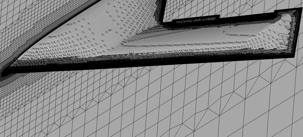


11 Figure 5: Crow and split flap geometries Figure 6: ICEM grid for clean configuration Figure 7: BOXERMesh grid for crow flaps Figure 8: Cp Color bar for flow visualization, applies to figures 1, 12, 14, 16, 18, 2 and 22 11
12 1.8 R26459 M.5 B. R M.5 B. TFree Cobalt M.5 B R26459 M.5 B. R M.5 B. TFree Cobalt M.5 B C L.4 C D R26459 M.5 B. R M.5 B. TFree Cobalt M.5 B R26442-R26459 M.5 R26465-R26459 M.5 Cobalt M.5 B5..2 C M C nβ Figure 9: Clean configuration forces and moments M= Figure 1: Clean configuration flow visualization M=.5, C p and skin friction streamlines 12

13 1.8 R26447 M.7 B. R26424 M.7 B. TFree Cobalt M.7 B. Cobalt M.7 B. TStrip.2 5 R26447 M.7 B. R26424 M.7 B. TFree Cobalt M.7 B. Cobalt M.7 B. TStrip.6 C L.4 C D R26447 M.7 B. R26424 M.7 B. TFree Cobalt M.7 B. Cobalt M.7 B. TStrip R26449-R26447 M.7 R26461-R26447 M.7 Cobalt M.7 B5..2 C M C nβ Figure 11: Clean configuration forces and moments M= Figure 12: Clean configuration flow visualization M=.7, C p and skin friction streamlines 13
14 1.8 R26428 M.8 B. Cobalt M.8 B..2 R26428 M.8 B. Cobalt M.8 B. 5.6 C L.4 C D R26428 M.8 B. Cobalt M.8 B..8 R26427-R26428 M.8 Cobalt M.8 B C M C nβ Figure 13: Clean configuration forces and moments M= Figure 14: Clean configuration flow visualization M=.8, C p and skin friction streamlines 14
15 1.8 R26458 M.9 B. R M.9 B. TFree Cobalt M.9 B..2 R26458 M.9 B. R M.9 B. TFree Cobalt M.9 B. 5.6 C L.4 C D R26458 M.9 B. R M.9 B. TFree Cobalt M.9 B C M C nβ Figure 15: Clean configuration forces and moments M= R26453-R26458 M.9 R26464-R26458 M.9 Cobalt M.9 B Figure 16: Clean configuration flow visualization M=.9, C p and skin friction streamlines 15
 incremental forces Figure 18: Inboard flaps (config 1, config 2) flow visualization, C p and skin friction streamlines 16")
16 .2 HSWT IB+1 HSWT IB-1 Cobalt IB+1 Cobalt IB-1.2 HSWT IB+1 HSWT IB-1 Cobalt IB+1 Cobalt IB C l C m HSWT IB+1 HSWT IB-1 Cobalt IB+1 Cobalt IB C n Figure 17: Inboard flaps (config 1, config 2) incremental forces Figure 18: Inboard flaps (config 1, config 2) flow visualization, C p and skin friction streamlines 16
17 .2 HSWT OB+1 HSWT OB-1 Cobalt OB+1 Cobalt OB-1.2 HSWT OB+1 HSWT OB-1 Cobalt OB+1 Cobalt OB C l C m HSWT OB+1 HSWT OB-1 Cobalt OB+1 Cobalt OB C n Figure 19: Outboard flaps (config 3, config 4) incremental forces Figure 2: Outboard flaps (config 3, config 4) flow visualization, C p and skin friction streamlines 17

18 HSWT OB Split+1 Cobalt OB Split +1 HSWT OB Split+1 Cobalt OB Split C l C m HSWT OB Split+1 Cobalt OB Split +1 HSWT OB Split+1 Cobalt OB Split C n C n Figure 21: Split flap (config 5) incremental forces l Figure 22: Split flap (config 5) flow visualization, C p and skin friction streamlines 18
19 Figure 23: Split flap (config 5) flow visualization, rear view, C p and skin friction streamlines.2 HSWT IB+1 OB-1 HSWT IB-1 OB+1 Cobalt IB+1 OB-1 Cobalt IB-1 OB+1.2 HSWT IB+1 OB-1 HSWT IB-1 OB+1 Cobalt IB+1 OB-1 Cobalt IB-1 OB C l C m HSWT IB+1 OB-1 HSWT IB-1 OB+1 Cobalt IB+1 OB-1 Cobalt IB-1 OB C n Figure 24: Crow flaps (config 6, config 7) incremental forces 19
20 Figure 25: Crow flaps (config 6, config 7) flow visualization, C p and skin friction streamlines.2 C F HSWT IB+1 OB-1 Cobalt IB+1 OB-1 Cobalt IB+1 OB-1 Coarse Cobalt IB+1 OB-1 Fine.2 C F HSWT IB+1 OB-1 Cobalt IB+1 OB-1 Cobalt IB+1 OB-1 Coarse Cobalt IB+1 OB-1 Fine C F.5 C l C F C m F C C F C F HSWT IB+1 OB-1 Cobalt IB+1 OB-1 Cobalt IB+1 OB-1 Coarse Cobalt IB+1 OB-1 Fine C F C n -.5 CF Figure 26 Crow flaps (config 6) mesh refinement incremental forces 2
NUMERICAL 3D TRANSONIC FLOW SIMULATION OVER A WING
 Review of the Air Force Academy No.3 (35)/2017 NUMERICAL 3D TRANSONIC FLOW SIMULATION OVER A WING Cvetelina VELKOVA Department of Technical Mechanics, Naval Academy Nikola Vaptsarov,Varna, Bulgaria (cvetelina.velkova1985@gmail.com)
The Spalart Allmaras turbulence model
 The Spalart Allmaras turbulence model The main equation The Spallart Allmaras turbulence model is a one equation model designed especially for aerospace applications; it solves a modelled transport equation
Introduction to ANSYS CFX
 Workshop 03 Fluid flow around the NACA0012 Airfoil 16.0 Release Introduction to ANSYS CFX 2015 ANSYS, Inc. March 13, 2015 1 Release 16.0 Workshop Description: The flow simulated is an external aerodynamics
Application of Wray-Agarwal Turbulence Model for Accurate Numerical Simulation of Flow Past a Three-Dimensional Wing-body
 Washington University in St. Louis Washington University Open Scholarship Mechanical Engineering and Materials Science Independent Study Mechanical Engineering & Materials Science 4-28-2016 Application
High-Lift Aerodynamics: STAR-CCM+ Applied to AIAA HiLiftWS1 D. Snyder
 High-Lift Aerodynamics: STAR-CCM+ Applied to AIAA HiLiftWS1 D. Snyder Aerospace Application Areas Aerodynamics Subsonic through Hypersonic Aeroacoustics Store release & weapons bay analysis High lift devices
GRID PATTERN EFFECTS ON AERODYNAMIC CHARACTERISTICS OF GRID FINS
 24 TH INTERNATIONAL CONGRESS OF THE AERONAUTICAL SCIENCES GRID PATTERN EFFECTS ON AERODYNAMIC CHARACTERISTICS OF GRID FINS Fumiya Hiroshima, Kaoru Tatsumi* *Mitsubishi Electric Corporation, Kamakura Works,
Missile External Aerodynamics Using Star-CCM+ Star European Conference 03/22-23/2011
 Missile External Aerodynamics Using Star-CCM+ Star European Conference 03/22-23/2011 StarCCM_StarEurope_2011 4/6/11 1 Overview 2 Role of CFD in Aerodynamic Analyses Classical aerodynamics / Semi-Empirical
NUMERICAL AND EXPERIMENTAL INVESTIGATIONS OF TEST MODELS AERODYNAMICS
 NUMERICAL AND EXPERIMENTAL INVESTIGATIONS OF TEST MODELS AERODYNAMICS A.V. Vaganov, S.M. Drozdov, S.M. Zadonsky, V.I. Plyashechnic, M.A. Starodubtsev, S.V. Chernov, V.L. Yumashev TsAGI, 140180 Zhukovsky,
Modeling External Compressible Flow
 Tutorial 3. Modeling External Compressible Flow Introduction The purpose of this tutorial is to compute the turbulent flow past a transonic airfoil at a nonzero angle of attack. You will use the Spalart-Allmaras
A DRAG PREDICTION VALIDATION STUDY FOR AIRCRAFT AERODYNAMIC ANALYSIS
 A DRAG PREDICTION VALIDATION STUDY FOR AIRCRAFT AERODYNAMIC ANALYSIS Akio OCHI, Eiji SHIMA Kawasaki Heavy Industries, ltd Keywords: CFD, Drag prediction, Validation Abstract A CFD drag prediction validation
Introduction to CFX. Workshop 2. Transonic Flow Over a NACA 0012 Airfoil. WS2-1. ANSYS, Inc. Proprietary 2009 ANSYS, Inc. All rights reserved.
 Workshop 2 Transonic Flow Over a NACA 0012 Airfoil. Introduction to CFX WS2-1 Goals The purpose of this tutorial is to introduce the user to modelling flow in high speed external aerodynamic applications.
THE EFFECTS OF THE PLANFORM SHAPE ON DRAG POLAR CURVES OF WINGS: FLUID-STRUCTURE INTERACTION ANALYSES RESULTS
 March 18-20, 2013 THE EFFECTS OF THE PLANFORM SHAPE ON DRAG POLAR CURVES OF WINGS: FLUID-STRUCTURE INTERACTION ANALYSES RESULTS Authors: M.R. Chiarelli, M. Ciabattari, M. Cagnoni, G. Lombardi Speaker:
The Numerical Simulation of Civil Transportation High-lift Configuration
 Available online at www.sciencedirect.com ScienceDirect Procedia Engineering 00 (2014) 000 000 www.elsevier.com/locate/procedia APISAT2014, 2014 Asia-Pacific International Symposium on Aerospace Technology,
FAR-Wake Workshop, Marseille, May 2008
 Wake Vortices generated by an Aircraft Fuselage : Comparison of Wind Tunnel Measurements on the TAK Model with RANS and RANS-LES Simulations T. Louagie, L. Georges & P. Geuzaine Cenaero CFD-Multiphysics
An efficient method for predicting zero-lift or boundary-layer drag including aeroelastic effects for the design environment
 The Aeronautical Journal November 2015 Volume 119 No 1221 1451 An efficient method for predicting zero-lift or boundary-layer drag including aeroelastic effects for the design environment J. A. Camberos
Express Introductory Training in ANSYS Fluent Workshop 04 Fluid Flow Around the NACA0012 Airfoil
 Express Introductory Training in ANSYS Fluent Workshop 04 Fluid Flow Around the NACA0012 Airfoil Dimitrios Sofialidis Technical Manager, SimTec Ltd. Mechanical Engineer, PhD PRACE Autumn School 2013 -
AERODYNAMIC DESIGN OF FLYING WING WITH EMPHASIS ON HIGH WING LOADING
 AERODYNAMIC DESIGN OF FLYING WING WITH EMPHASIS ON HIGH WING LOADING M. Figat Warsaw University of Technology Keywords: Aerodynamic design, CFD Abstract This paper presents an aerodynamic design process
Finite Element Flow Simulations of the EUROLIFT DLR-F11 High Lift Configuration
 Finite Element Flow Simulations of the EUROLIFT DLR-F11 High Lift Configuration Kedar C. Chitale MANE Dept., Rensselaer Polytechnic Institute, NY 12180 Michel Rasquin Leadership Computing Facility, Argonne
Validation of an Unstructured Overset Mesh Method for CFD Analysis of Store Separation D. Snyder presented by R. Fitzsimmons
 Validation of an Unstructured Overset Mesh Method for CFD Analysis of Store Separation D. Snyder presented by R. Fitzsimmons Stores Separation Introduction Flight Test Expensive, high-risk, sometimes catastrophic
Grid. Apr 09, 1998 FLUENT 5.0 (2d, segregated, lam) Grid. Jul 31, 1998 FLUENT 5.0 (2d, segregated, lam)
 Grid. Jul 31, 1998 FLUENT 5.0 (2d, segregated, lam)") Tutorial 2. Around an Airfoil Transonic Turbulent Flow Introduction: The purpose of this tutorial is to compute the turbulent flow past a transonic airfoil at a non-zero angle of attack. You will use the
Tutorial 2. Around an Airfoil Transonic Turbulent Flow Introduction: The purpose of this tutorial is to compute the turbulent flow past a transonic airfoil at a non-zero angle of attack. You will use the
(c)2002 American Institute of Aeronautics & Astronautics or Published with Permission of Author(s) and/or Author(s)' Sponsoring Organization.
2002 American Institute of Aeronautics & Astronautics or Published with Permission of Author(s) and/or Author(s)' Sponsoring Organization.") VIIA Adaptive Aerodynamic Optimization of Regional Introduction The starting point of any detailed aircraft design is (c)2002 American Institute For example, some variations of the wing planform may become
VIIA Adaptive Aerodynamic Optimization of Regional Introduction The starting point of any detailed aircraft design is (c)2002 American Institute For example, some variations of the wing planform may become
Optimate CFD Evaluation Optimate Glider Optimization Case
 Optimate CFD Evaluation Optimate Glider Optimization Case Authors: Nathan Richardson LMMFC CFD Lead 1 Purpose For design optimization, the gold standard would be to put in requirements and have algorithm
Keywords: CFD, aerofoil, URANS modeling, flapping, reciprocating movement
 L.I. Garipova *, A.N. Kusyumov *, G. Barakos ** * Kazan National Research Technical University n.a. A.N.Tupolev, ** School of Engineering - The University of Liverpool Keywords: CFD, aerofoil, URANS modeling,
Usage of CFX for Aeronautical Simulations
 Usage of CFX for Aeronautical Simulations Florian Menter Development Manager Scientific Coordination ANSYS Germany GmbH Overview Elements of CFD Technology for aeronautical simulations: Grid generation
APPLICATION OF A NAVIER-STOKES SOLVER TO THE ANALYSIS OF MULTIELEMENT AIRFOILS AND WINGS USING MULTIZONAL GRID TECHNIQUES
 APPLICATION OF A NAVIER-STOKES SOLVER TO THE ANALYSIS OF MULTIELEMENT AIRFOILS AND WINGS USING MULTIZONAL GRID TECHNIQUES Kenneth M. Jones* NASA Langley Research Center Hampton, VA Robert T. Biedron Analytical
Experimental study of UTM-LST generic half model transport aircraft
 IOP Conference Series: Materials Science and Engineering PAPER OPEN ACCESS Experimental study of UTM-LST generic half model transport aircraft To cite this article: M I Ujang et al 2016 IOP Conf. Ser.:
Post Stall Behavior of a Lifting Line Algorithm
 Post Stall Behavior of a Lifting Line Algorithm Douglas Hunsaker Brigham Young University Abstract A modified lifting line algorithm is considered as a low-cost approach for calculating lift characteristics
AERODYNAMIC DESIGN FOR WING-BODY BLENDED AND INLET
 25 TH INTERNATIONAL CONGRESS OF THE AERONAUTICAL SCIENCES AERODYNAMIC DESIGN FOR WING-BODY BLENDED AND INLET Qingzhen YANG*,Yong ZHENG* & Thomas Streit** *Northwestern Polytechincal University, 772,Xi
Computational Fluid Dynamics Analysis of an Idealized Modern Wingsuit
 Washington University in St. Louis Washington University Open Scholarship Mechanical Engineering and Materials Science Independent Study Mechanical Engineering & Materials Science 12-21-2016 Computational
Detached-Eddy Simulation of a Linear Compressor Cascade with Tip Gap and Moving Wall *)
") FOI, Stockholm, Sweden 14-15 July, 2005 Detached-Eddy Simulation of a Linear Compressor Cascade with Tip Gap and Moving Wall *) A. Garbaruk,, M. Shur, M. Strelets, and A. Travin *) Study is carried out
FOI, Stockholm, Sweden 14-15 July, 2005 Detached-Eddy Simulation of a Linear Compressor Cascade with Tip Gap and Moving Wall *) A. Garbaruk,, M. Shur, M. Strelets, and A. Travin *) Study is carried out
Detached Eddy Simulation Analysis of a Transonic Rocket Booster for Steady & Unsteady Buffet Loads
 Detached Eddy Simulation Analysis of a Transonic Rocket Booster for Steady & Unsteady Buffet Loads Matt Knapp Chief Aerodynamicist TLG Aerospace, LLC Presentation Overview Introduction to TLG Aerospace
Evaluation of CFD simulation on boundary between meshes of different types
 Evaluation of CFD simulation on boundary between meshes of different types Tomáš Radnic 1,*, Pavel Šafařík 1 1 ČVUT v Praze, Fakulta strojní, Ústav Mechaniky Tekutin a termomechaniky, Technická 4, 166
X-31A VECTOR High Angle of Attack Descent Euler and Navier-Stokes Simulations of Unsteady Manoeuvres
 X-31A VECTOR High Angle of Attack Descent Euler and Navier-Stokes Simulations of Unsteady Manoeuvres Stephan M. Hitzel, Edwin van der Weide, Udo Tremel, Herbert Rieger Numerical Flow Simulation, EADS Military
Estimation of Flow Field & Drag for Aerofoil Wing
 Estimation of Flow Field & Drag for Aerofoil Wing Mahantesh. HM 1, Prof. Anand. SN 2 P.G. Student, Dept. of Mechanical Engineering, East Point College of Engineering, Bangalore, Karnataka, India 1 Associate
German Aerospace Center, Institute of Aerodynamics and Flow Technology, Numerical Methods
 Automatische Transitionsvorhersage im DLR TAU Code Status der Entwicklung und Validierung Automatic Transition Prediction in the DLR TAU Code - Current Status of Development and Validation Andreas Krumbein
COMPUTATIONAL FLUID DYNAMICS ANALYSIS OF ORIFICE PLATE METERING SITUATIONS UNDER ABNORMAL CONFIGURATIONS
 COMPUTATIONAL FLUID DYNAMICS ANALYSIS OF ORIFICE PLATE METERING SITUATIONS UNDER ABNORMAL CONFIGURATIONS Dr W. Malalasekera Version 3.0 August 2013 1 COMPUTATIONAL FLUID DYNAMICS ANALYSIS OF ORIFICE PLATE
CFD Methods for Aerodynamic Design
 CFD Methods for Aerodynamic Design Afandi Darlington Optimal Aerodynamics Ltd Why CFD? Datasheet methods are still very relevant today (ESDU, USAF DATCOM) Validated estimates of lift, drag, moments, stability
Validation of a numerical simulation tool for aircraft formation flight.
 Validation of a numerical simulation tool for aircraft formation flight. T. Melin Fluid and Mechatronic Systems, Department of Management and Engineering, the Institute of Technology, Linköping University,
NUMERICAL SIMULATIONS OF FLOW THROUGH AN S-DUCT
 NUMERICAL SIMULATIONS OF FLOW THROUGH AN S-DUCT 1 Pravin Peddiraju, 1 Arthur Papadopoulos, 2 Vangelis Skaperdas, 3 Linda Hedges 1 BETA CAE Systems USA, Inc., USA, 2 BETA CAE Systems SA, Greece, 3 CFD Consultant,
Flow Field of Truncated Spherical Turrets
 Flow Field of Truncated Spherical Turrets Kevin M. Albarado 1 and Amelia Williams 2 Aerospace Engineering, Auburn University, Auburn, AL, 36849 Truncated spherical turrets are used to house cameras and
Verification and Validation of Turbulent Flow around a Clark-Y Airfoil
 Verification and Validation of Turbulent Flow around a Clark-Y Airfoil 1. Purpose 58:160 Intermediate Mechanics of Fluids CFD LAB 2 By Tao Xing and Fred Stern IIHR-Hydroscience & Engineering The University
Transition Flow and Aeroacoustic Analysis of NACA0018 Satish Kumar B, Fred Mendonç a, Ghuiyeon Kim, Hogeon Kim
 Transition Flow and Aeroacoustic Analysis of NACA0018 Satish Kumar B, Fred Mendonç a, Ghuiyeon Kim, Hogeon Kim Transition Flow and Aeroacoustic Analysis of NACA0018 Satish Kumar B, Fred Mendonç a, Ghuiyeon
AIR LOAD CALCULATION FOR ISTANBUL TECHNICAL UNIVERSITY (ITU), LIGHT COMMERCIAL HELICOPTER (LCH) DESIGN ABSTRACT
, LIGHT COMMERCIAL HELICOPTER (LCH) DESIGN ABSTRACT") AIR LOAD CALCULATION FOR ISTANBUL TECHNICAL UNIVERSITY (ITU), LIGHT COMMERCIAL HELICOPTER (LCH) DESIGN Adeel Khalid *, Daniel P. Schrage + School of Aerospace Engineering, Georgia Institute of Technology
AIR LOAD CALCULATION FOR ISTANBUL TECHNICAL UNIVERSITY (ITU), LIGHT COMMERCIAL HELICOPTER (LCH) DESIGN Adeel Khalid *, Daniel P. Schrage + School of Aerospace Engineering, Georgia Institute of Technology
Study of Swept Angle Effects on Grid Fins Aerodynamics Performance
 Journal of Physics: Conference Series PAPER OPEN ACCESS Study of Swept Angle Effects on Grid Fins Aerodynamics Performance To cite this article: G A Faza et al 2018 J. Phys.: Conf. Ser. 1005 012013 View
SMALL HEIGHT DUCT DESIGN FOR MULTICOPTER FAN
 SMALL HEIGHT DUCT DESIGN FOR MULTICOPTER FAN Stremousov K.*, Arkhipov M.*, Serokhvostov S.* *Moscow Institute of Physics and Technology, Department of Aeromechanics and Flight Engineering 16, Gagarina
A Computational Study of the Abrupt Wing Stall (AWS) Characteristics for Various Fighter Jets: Part I, F/A-18E and F-16C
 Characteristics for Various Fighter Jets: Part I, F/A-18E and F-16C") AIAA 2003-0746 A Computational Study of the Abrupt Wing Stall (AWS) Characteristics for Various Fighter Jets: Part I, F/A-18E and F-16C Paresh Parikh NASA Langley Research Center, Hampton, VA James Chung
AIAA 2003-0746 A Computational Study of the Abrupt Wing Stall (AWS) Characteristics for Various Fighter Jets: Part I, F/A-18E and F-16C Paresh Parikh NASA Langley Research Center, Hampton, VA James Chung
LES Applications in Aerodynamics
 LES Applications in Aerodynamics Kyle D. Squires Arizona State University Tempe, Arizona, USA 2010 Tutorial School on Fluid Dynamics: Topics in Turbulence Center for Scientific Computation and Mathematical
Chapter 34 LESSONS LEARNED FROM THE NUMERICAL INVESTIGATIONS ON THE VFE-2 CONFIGURATION
 Chapter 34 LESSONS LEARNED FROM THE NUMERICAL by Willy Fritz 1 and Russell M. Cummings 2 The Second International Vortex Flow Experiment provided a variety of experimental data for a 65 delta wing with
Evaluation of Flow Solver Accuracy using Five Simple Unsteady Validation Cases
 Evaluation of Flow Solver Accuracy using Five Simple Unsteady Validation Cases Bradford E. Green, Ryan Czerwiec Naval Air Systems Command, Patuxent River, MD, 20670 Chris Cureton, Chad Lillian, Sergey
Profile Catalogue for Airfoil Sections Based on 3D Computations
 Risø-R-58(EN) Profile Catalogue for Airfoil Sections Based on 3D Computations Franck Bertagnolio, Niels N. Sørensen and Jeppe Johansen Risø National Laboratory Roskilde Denmark December 26 Author: Franck
THE SECOND INTERNATIONAL VORTEX FLOW EXPERIMENT (VFE-2): RESULTS OF THE FIRST PHASE
: RESULTS OF THE FIRST PHASE") 26 TH INTERNATIONAL CONGRESS OF THE AERONAUTICAL SCIENCES THE SECOND INTERNATIONAL VORTEX FLOW EXPERIMENT (VFE-2): RESULTS OF THE FIRST PHASE 2003-2008 Dietrich Hummel Technische Universität Braunschweig
26 TH INTERNATIONAL CONGRESS OF THE AERONAUTICAL SCIENCES THE SECOND INTERNATIONAL VORTEX FLOW EXPERIMENT (VFE-2): RESULTS OF THE FIRST PHASE 2003-2008 Dietrich Hummel Technische Universität Braunschweig
Aerodynamics of 3D Lifting Surfaces through Vortex Lattice Methods. Introduction to Applications of VLM
 Aerodynamics of 3D Lifting Surfaces through Vortex Lattice Methods Introduction to Applications of VLM Basic Concepts Boundary conditions on the mean surface Vortex Theorems, Biot-Savart Law The Horseshoe
Debojyoti Ghosh. Adviser: Dr. James Baeder Alfred Gessow Rotorcraft Center Department of Aerospace Engineering
 Debojyoti Ghosh Adviser: Dr. James Baeder Alfred Gessow Rotorcraft Center Department of Aerospace Engineering To study the Dynamic Stalling of rotor blade cross-sections Unsteady Aerodynamics: Time varying
LES Analysis on Shock-Vortex Ring Interaction
 LES Analysis on Shock-Vortex Ring Interaction Yong Yang Jie Tang Chaoqun Liu Technical Report 2015-08 http://www.uta.edu/math/preprint/ LES Analysis on Shock-Vortex Ring Interaction Yong Yang 1, Jie Tang
Nomenclature. = Reference length of the model (root chord of the model) c p. I. Introduction
 c p. I. Introduction") 46th AIAA Aerospace Sciences Meeting and Exhibit AIAA 2008-396 7-10 January 2008, Reno, Nevada Detached-Eddy Simulation of the Vortical Flowfield about the VFE-2 Delta Wing Russell M. Cummings * and Andreas
46th AIAA Aerospace Sciences Meeting and Exhibit AIAA 2008-396 7-10 January 2008, Reno, Nevada Detached-Eddy Simulation of the Vortical Flowfield about the VFE-2 Delta Wing Russell M. Cummings * and Andreas
DYNAMICS OF A VORTEX RING AROUND A MAIN ROTOR HELICOPTER
 DYNAMICS OF A VORTEX RING AROUND A MAIN ROTOR HELICOPTER Katarzyna Surmacz Instytut Lotnictwa Keywords: VORTEX RING STATE, HELICOPTER DESCENT, NUMERICAL ANALYSIS, FLOW VISUALIZATION Abstract The main goal
Second Symposium on Hybrid RANS-LES Methods, 17/18 June 2007
 1 Zonal-Detached Eddy Simulation of Transonic Buffet on a Civil Aircraft Type Configuration V.BRUNET and S.DECK Applied Aerodynamics Department The Buffet Phenomenon Aircraft in transonic conditions Self-sustained
Flow control and high lift performance for flying wing manned Combat Air Vehicle Configurations by inserting lots
 Flow control and high lift performance for flying wing manned Combat Air Vehicle Configurations by inserting lots Ali, U and Chadwick, EA 10.21152/1750 9548.10.2.117 Title Authors Type URL Flow control
Numerical Simulation Study on Aerodynamic Characteristics of the High Speed Train under Crosswind
 2017 2nd International Conference on Industrial Aerodynamics (ICIA 2017) ISBN: 978-1-60595-481-3 Numerical Simulation Study on Aerodynamic Characteristics of the High Speed Train under Crosswind Fan Zhao,
Potsdam Propeller Test Case (PPTC)
") Second International Symposium on Marine Propulsors smp 11, Hamburg, Germany, June 2011 Workshop: Propeller performance Potsdam Propeller Test Case (PPTC) Olof Klerebrant Klasson 1, Tobias Huuva 2 1 Core
Second International Symposium on Marine Propulsors smp 11, Hamburg, Germany, June 2011 Workshop: Propeller performance Potsdam Propeller Test Case (PPTC) Olof Klerebrant Klasson 1, Tobias Huuva 2 1 Core
Small Height Duct Design for 17 Multicopter Fan Considering Its Interference on Quad-copter
 Small Height Duct Design for 17 Multicopter Fan Considering Its Interference on Quad-copter Stremousov K.*, Arkhipov M.* **, Serokhvostov S.* ** * Moscow Institute of Physics and Technology, Department
Challenges in Boundary- Layer Stability Analysis Based On Unstructured Grid Solutions
 Challenges in Boundary- Layer Stability Analysis Based On Unstructured Grid Solutions Wei Liao National Institute of Aerospace, Hampton, Virginia Collaborators: Mujeeb R. Malik, Elizabeth M. Lee- Rausch,
Analysis of an airfoil
 UNDERGRADUATE RESEARCH FALL 2010 Analysis of an airfoil using Computational Fluid Dynamics Tanveer Chandok 12/17/2010 Independent research thesis at the Georgia Institute of Technology under the supervision
Aerodynamic Analysis of Forward Swept Wing Using Prandtl-D Wing Concept
 Aerodynamic Analysis of Forward Swept Wing Using Prandtl-D Wing Concept Srinath R 1, Sahana D S 2 1 Assistant Professor, Mangalore Institute of Technology and Engineering, Moodabidri-574225, India 2 Assistant
NUMERICAL AND EXPERIMENTAL ANALYSIS OF A REPRESENTATIVE ADF HELICOPTER FUSELAGE
 28 TH INTERNATIONAL CONGRESS OF THE AERONAUTICAL SCIENCES NUMERICAL AND EXPERIMENTAL ANALYSIS OF A REPRESENTATIVE ADF HELICOPTER FUSELAGE Dylan Brunello*, Gareth Clarke, Rami Reddy* *Defence Science Technology
CFD++ APPLICATION ON WIND TUNNEL DATA ANALYSIS
 CFD++ APPLICATION ON WIND TUNNEL DATA ANALYSIS Introduction Piaggio Aero Industries is actually studing a new mid size jet for civilian use. Many people and many disciplines are implicated but up to now
Effect of Position of Wall Mounted Surface Protrusion in Drag Characteristics At Low Reynolds Number
 ISSN (e): 2250 3005 Volume, 07 Issue, 11 November 2017 International Journal of Computational Engineering Research (IJCER) Effect of Position of Wall Mounted Surface Protrusion in Drag Characteristics
High-order solutions of transitional flow over the SD7003 airfoil using compact finite-differencing and filtering
 High-order solutions of transitional flow over the SD7003 airfoil using compact finite-differencing and filtering Daniel J. Garmann and Miguel R. Visbal Air Force Research Laboratory, Wright-Patterson
CFD SIMULATIONS OF HORIZONTAL AXIS WIND TURBINE (HAWT) BLADES FOR VARIATION WITH WIND SPEED
 BLADES FOR VARIATION WITH WIND SPEED") 2 nd National Conference on CFD Applications in Power and Industry Sectors January 28-29, 2009, Hydrabad, India CFD SIMULATIONS OF HORIZONTAL AXIS WIND TURBINE (HAWT) BLADES FOR VARIATION WITH WIND SPEED
2 nd National Conference on CFD Applications in Power and Industry Sectors January 28-29, 2009, Hydrabad, India CFD SIMULATIONS OF HORIZONTAL AXIS WIND TURBINE (HAWT) BLADES FOR VARIATION WITH WIND SPEED
COMPARISON OF SHOCK WAVE INTERACTION FOR THE THREE-DIMENSIONAL SUPERSONIC BIPLANE WITH DIFFERENT PLANAR SHAPES
 26 TH INTERNATIONAL CONGRESS OF THE AERONAUTICAL SCIENCES COMPARISON OF SHOCK WAVE INTERACTION FOR THE THREE-DIMENSIONAL SUPERSONIC BIPLANE WITH DIFFERENT PLANAR SHAPES M. Yonezawa*, H. Yamashita* *Institute
UNSTRUCTURED MESH CAPABILITES FOR SUPERSONIC WING DESIGN AT LOW SPEED CONDITIONS
 CFD & OPTIMIZATION 2011-048 An ECCOMAS Thematic Conference 23-25 May 2011, Antalya TURKEY UNSTRUCTURED MESH CAPABILITES FOR SUPERSONIC WING DESIGN AT LOW SPEED CONDITIONS Michele Gaffuri, Joël Brezillon
Investigation of cross flow over a circular cylinder at low Re using the Immersed Boundary Method (IBM)
") Computational Methods and Experimental Measurements XVII 235 Investigation of cross flow over a circular cylinder at low Re using the Immersed Boundary Method (IBM) K. Rehman Department of Mechanical Engineering,
Computational Methods and Experimental Measurements XVII 235 Investigation of cross flow over a circular cylinder at low Re using the Immersed Boundary Method (IBM) K. Rehman Department of Mechanical Engineering,
A STUDY ON THE UNSTEADY AERODYNAMICS OF PROJECTILES IN OVERTAKING BLAST FLOWFIELDS
 HEFAT2012 9 th International Conference on Heat Transfer, Fluid Mechanics and Thermodynamics 16 18 July 2012 Malta A STUDY ON THE UNSTEADY AERODYNAMICS OF PROJECTILES IN OVERTAKING BLAST FLOWFIELDS Muthukumaran.C.K.
AN INVERSE DESIGN METHOD FOR ENGINE NACELLES AND WINGS
 24th INTERNATIONAL CONGRESS OF THE AERONAUTICAL SCIENCES AN INVERSE DESIGN METHOD FOR ENGINE NACELLES AND WINGS Roland Wilhelm German Aerospace Center DLR, Lilienthalplatz 7, D-388 Braunschweig, Germany
Application of Chimera with Hexahedral Blocks in Solar Meshes
 Application of Chimera with Hexahedral Blocks in Solar Meshes Simone Crippa Institut für Aerodynamik und Strömungstechnik, DLR, 38108, Braunschweig Abstract The Chimera methodology of the DLR TAU solver
Design and Computational Fluid Dynamics Analysis of an Idealized Modern Wingsuit
 Design and Computational Fluid Dynamics Analysis of an Idealized Modern Wingsuit Maria E. Ferguson Washington University in St. Louis Advisor: Dr. Ramesh K. Agarwal Abstract The modern wingsuit has been
Application of STAR-CCM+ to Helicopter Rotors in Hover
 Application of STAR-CCM+ to Helicopter Rotors in Hover Lakshmi N. Sankar and Chong Zhou School of Aerospace Engineering, Georgia Institute of Technology, Atlanta, GA Ritu Marpu Eschol CD-Adapco, Inc.,
COMPUTATIONAL AND EXPERIMENTAL INTERFEROMETRIC ANALYSIS OF A CONE-CYLINDER-FLARE BODY. Abstract. I. Introduction
 COMPUTATIONAL AND EXPERIMENTAL INTERFEROMETRIC ANALYSIS OF A CONE-CYLINDER-FLARE BODY John R. Cipolla 709 West Homeway Loop, Citrus Springs FL 34434 Abstract A series of computational fluid dynamic (CFD)
NSU3D Results for the Fourth AIAA Drag Prediction Workshop
 NSU3D Results for the Fourth AIAA Drag Prediction Workshop Dimitri Mavriplis Mike Long Department of Mechanical Engineering University of Wyoming, Laramie, Wyoming, 82072-3295 Simulation results for the
LAMDES User s Manual VLMpc
 LAMDES User s Manual This is a modified version of John Lamar s design program (Ref. 1). It is based on the vortex lattice program VLMpc, but converted to do design and optimization. Basic capabilities
Impact of Computational Aerodynamics on Aircraft Design
 Impact of Computational Aerodynamics on Aircraft Design Outline Aircraft Design Process Aerodynamic Design Process Wind Tunnels &Computational Aero. Impact on Aircraft Design Process Revealing details
Computation of Sensitivity Derivatives of Navier-Stokes Equations using Complex Variables
 Computation of Sensitivity Derivatives of Navier-Stokes Equations using Complex Variables By Veer N. Vatsa NASA Langley Research Center, Hampton, VA 23681 Mail Stop 128, email: v.n.vatsa@larc.nasa.gov
AERODYNAMIC OPTIMIZATION OF A FORMULA STUDENT CAR
 AERODYNAMIC OPTIMIZATION OF A FORMULA STUDENT CAR 1 Argyrios Apostolidis *, 2 Athanasios Mattas, 3 Aggelos Gaitanis, 4 Nikolaos Christodoulou 1 Aristotle Racing Team, Greece, 4 BETA CAE Systems S.A., Greece
Research Directions in. Unsteady Aerodynamics
 APS DFD 2004 Seattle Research Directions in Unsteady Aerodynamics P. Spalart* Boeing Commercial Airplanes *with Strelets and Squires Outline Theory: )-: Computational Fluid Dynamics Resolved and modeled
Yann Le Moigne. NFFP 542 Project report. CFD simulations of an S-duct with conventional vortex generators and comparison with experimental data
 November 2004 1650-1942 Scientific report Yann Le Moigne NFFP 542 Project report CFD simulations of an S-duct with conventional vortex generators and comparison with experimental data Division of Aeronautics,
Case C3.1: Turbulent Flow over a Multi-Element MDA Airfoil
 Case C3.1: Turbulent Flow over a Multi-Element MDA Airfoil Masayuki Yano and David L. Darmofal Aerospace Computational Design Laboratory, Massachusetts Institute of Technology I. Code Description ProjectX
F- 16XL Unsteady Simulations for the CAWAPI Facet of RTO Task Group AVT- 113
 F- 16XL Unsteady Simulations for the CAWAPI Facet of RTO Task Group AVT- 113 Scott A. Morton * United States Air Force SEEK EAGLE Office, Eglin AFB, FL 32542 and David R. McDaniel and Russell M. Cummings
AAE490 - Design of a Contraction for a Transonic Ludwieg Tube
 AAE490 - Design of a Contraction for a Transonic Ludwieg Tube Report No. 3 November 30, 1998 Shin Matsumura School of Aeronautics and Astronautics Purdue University West Lafayette, IN ABSTRACT The Mach
ANSYS FLUENT. Airfoil Analysis and Tutorial
 ANSYS FLUENT Airfoil Analysis and Tutorial ENGR083: Fluid Mechanics II Terry Yu 5/11/2017 Abstract The NACA 0012 airfoil was one of the earliest airfoils created. Its mathematically simple shape and age
Hybrid Simulation of Wake Vortices during Landing HPCN-Workshop 2014
 Hybrid Simulation of Wake Vortices during Landing HPCN-Workshop 2014 A. Stephan 1, F. Holzäpfel 1, T. Heel 1 1 Institut für Physik der Atmosphäre, DLR, Oberpfaffenhofen, Germany Aircraft wake vortices
INTEGRATING EXPERIMENTS AND CFD IN WEAPON AERODYNAMICS
 INTEGRATING EXPERIMENTS AND CFD IN WEAPON AERODYNAMICS T J Birch Contents Introduction to weapon aerodynamics Airframe design and aerodynamic data requirements Aerodynamic data sources Engineering methods,
1 Introduction. 2 Simulation and experimental works. Acta Polytechnica Vol. 44 No. 2/2004
 Acta Polytechnica Vol. 44 No. 2/24 Computational Fluid Dynamic Simulation (CFD) and Experimental Study on Wing-external Store Aerodynamic Interference of a Subsonic Fighter Aircraft Tholudin Mat Lazim,
Computational Study of the Aerodynamic Performance of Subsonic Scarf Inlets
 40th AIAA/ASME/SAE/ASEE Joint Propulsion Conference and Exhibit 11-14 July 2004, Fort Lauderdale, Florida AIAA 2004-3406 Computational Study of the Aerodynamic Performance of Subsonic Scarf Inlets John
Summary of the main PROBAND project results
 Summary of the main PROBAND project results WP2: WP2 was dedicated to the development and validation broadband noise prediction methods. Once validated on non rotating airfoils in WP2, these methods were
CFD-1. Introduction: What is CFD? T. J. Craft. Msc CFD-1. CFD: Computational Fluid Dynamics
 School of Mechanical Aerospace and Civil Engineering CFD-1 T. J. Craft George Begg Building, C41 Msc CFD-1 Reading: J. Ferziger, M. Peric, Computational Methods for Fluid Dynamics H.K. Versteeg, W. Malalasekara,
Research Article A Computational Investigation of Unsteady Aerodynamics of Insect-Inspired Fixed Wing Micro Aerial Vehicle s 2D Airfoil
 Advances in Aerospace Engineering, Article ID 5449, 7 pages http://dx.doi.org/1.1155/214/5449 Research Article A Computational Investigation of Unsteady Aerodynamics of Insect-Inspired Fixed Wing Micro
LOW-SPEED HIGH-LIFT PERFORMANCE IMPROVEMENTS OBTAINED AND VALIDATED BY THE EC-PROJECT EPISTLE
 24 TH INTERNATIONAL CONGRESS OF THE AERONAUTICAL SCIENCES LOW-SPEED HIGH-LIFT PERFORMANCE IMPROVEMENTS OBTAINED AND VALIDATED BY THE EC-PROJECT EPISTLE U. Herrmann DLR, Institute of Aerodynamics and Flow
NASA Rotor 67 Validation Studies
 NASA Rotor 67 Validation Studies ADS CFD is used to predict and analyze the performance of the first stage rotor (NASA Rotor 67) of a two stage transonic fan designed and tested at the NASA Glenn center
HPC Usage for Aerodynamic Flow Computation with Different Levels of Detail
 DLR.de Folie 1 HPCN-Workshop 14./15. Mai 2018 HPC Usage for Aerodynamic Flow Computation with Different Levels of Detail Cornelia Grabe, Marco Burnazzi, Axel Probst, Silvia Probst DLR, Institute of Aerodynamics
Computational Fluid Dynamics Simulation of a Rim Driven Thruster
 Computational Fluid Dynamics Simulation of a Rim Driven Thruster Aleksander J Dubas, N. W. Bressloff, H. Fangohr, S. M. Sharkh (University of Southampton) Abstract An electric rim driven thruster is a