Calibration. Reality. Error. Measuring device. Model of Reality Fall 2001 Copyright R. H. Taylor 1999, 2001
|
|
|
- Emma Patterson
- 6 years ago
- Views:
Transcription
1 Calibration Calibrate (vt) : 1. to determine the caliber of (as a thermometer tube); 2. to determine, rectify, or mark the gradations of (as a thermometer tube); 3. to standardize (as a measuring instrument) by determining the deviation from a standard so as to ascertain the proper correction factors; 4. ADJUST, TUNE
2 Calibration Reality Measuring device + - Error Model of Reality
3 Calibration Reality Actuation device + - Error Model of Reality
4 Basic Techniques Parameter Estimation Mapping the space
5 Parameter Estimation Compare observed system performance to reference standard ( ground truth ) Compute parameters of mathematical model that minimizes residual error. System Parameters + - Model of reality Reality Error Calibration process
6 Pointing device calibration p pivot p t (unknown) F = ( R, p ) i i i
7 Pointing device calibration p pivot p t (unknown) F = ( R, p ) i i i
8 Pointing device calibration p pivot p t F = ( R, p ) i i i
9 Pointing device calibration p pivot p t (unknown) Rp + p = p i t i pivot F = ( R, p ) i i i
10 Pointing device calibration p pivot p t (unknown) p t R I p p j pivot j F = ( R, p ) i i i
11 Linear Parameter Estimation p = f( q) where q= [ q,... q nom 1 n T ] are parameters * p = f( q+ q) L fi f( q) + ( q) q NM j f( q) + J ( q) q f O L QP NM q q 1 n O QP
12 Linear Parameter Estimation Given f(q), and a set of observations p k * corresponding to nominal parameter values q k *, solve the least squares problem L NM O QP L NM * f ( q ) q p f( q ) J k k k O QP
13 Example: 2 link robot calibration a 2 * p k a 1
14 Example: 2 link robot calibration a 2 * p k a 1
15 Example: 2 link robot calibration p = L NM a a sinθ + a sin( θ ) cosθ + a cos( θ ) O QP where θ = θ + θ p * = L NM ( a1+ a1)sin( θ1+ θ1) + ( a2 + a2)sin( θ12 + θ1+ θ2) 0 ( a + a cos( θ + θ ) + ( a + a ) cos( θ + θ + θ ) O QP
16 Example: 2 link robot calibration p = f( q ) = f( a, a, θ, θ ) = k k L NM a1sinθ1, k + a2sin( θ12, k) 0 a cosθ + a cos( θ ) 1 1, k 2 12, k O QP where θ = θ + θ so we solve the least squares problem L NM f a OL QP NM a1 f f f a 2 ( q ) ( q ) ( q ) ( q ) a θ θ θ 1P θ arot 1 ( y, θ 1 k ) + arot( y, θ ) * k k k k p, k , k 2 O Q L NM L M N O QP O P Q
17 Example: 2 link robot calibration Here so J f L NM ( q ) = k L NM sinθ sin θ a (cosθ + cos θ ) a cosθ , k 12, k 1 1, k 12, k 2 12, k cosθ cos θ a (sinθ + sin θ ) a cosθ 1, k 12, k 1 1, k 12, k 2 12, k a 1 sinθ, k sin θ, k a (cosθ, k + cos θ, k) a cosθ , k a cosθ, k cos θ, k a (sinθ, k + sin θ, k) a cosθ , k θ PM 1P θ OL QN 2 O Q O QP L NM x a sinθ + a sin( θ ) z a cos a cos( ) * k 1 1, k 2 12, k * k 1 θ1, k + 2 θ12, k O QP
18
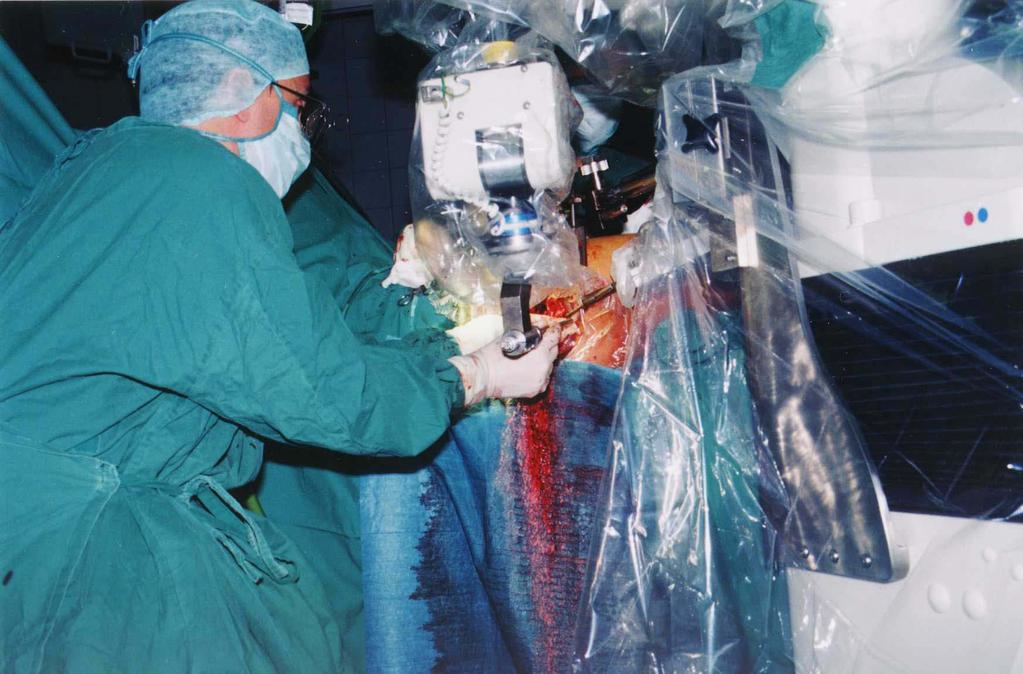
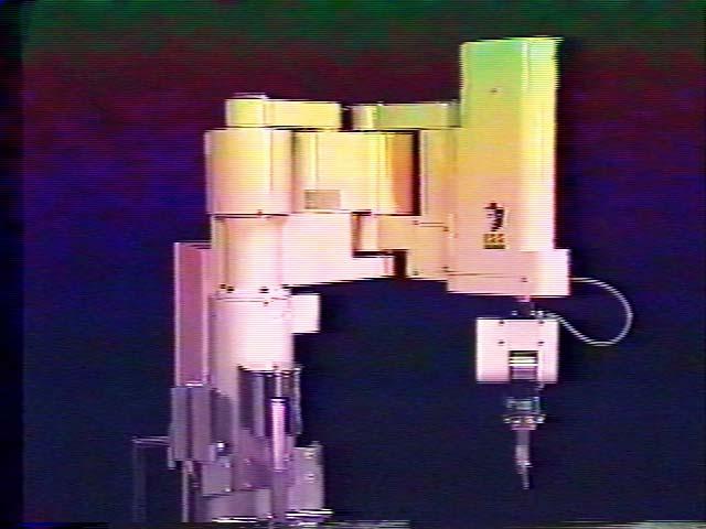
19 Example: Robodoc Wrist Calibration Basic robot had very accurate calibration Custom wrist was less accurate Crucial goal was to determine position of cutter tip Cutter Calibration post
20
21 Kinematic Model p = p + R( z, θ + θ ) ( α x+ v ) tool wrist 4 4 distal v = R( x, β ) [ R( y, θ + θ )( v + v )] distal 5 5 c c
22 Linearization p p + [ R R ( v + v )] +... post wrist 4 5 c c
23 Linear Least Squares Most commonly used method for parameter estimation Many numerical libraries See the web site Here is a quick review Microsoft PowerPoint Presentation
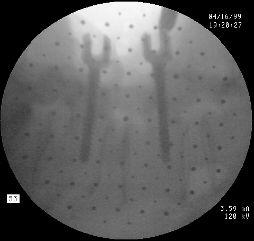
24 Example: Undistorted fluoroscope calibration
25 Calibration if no distortion (version 1) Assume no distortion. For the moment also assume that you have N point calibration features (e.g., small steel balls) at known { } positions a0,, a N 1 relative to the detector. Assume further that the points { } create images at corresponding points d0,, d N 1 on the detector. Estimate the position s of the x-ray source relative to the detector
26 Approach F obj s Calibration object a k d k Detector
27 Projection of a point feature s s= λ(a-d)+d (a - d) (s - d) λ = (a - d) (a - d) a d d= µ ( a s) + s µ = (a - s) (d - s) (a - s) (a - s)
28 Approach s d a ( a d) ( s d) = 0 skew( a d) s = ( a d) d = a d d d = a d 0 dz az ay dy az dz 0 dx ax s = a d dy ay ax dx 0
29 Solve least squares problem Approach skew( a0 d0) sx a0 d0 s y s z skew( N 1 N 1) a d an 1 dn 1 s a d
30 What if pose of calibration object is imprecisely known? This is a hairier problem, but solvable In fact, it makes a great homework assignment.
31 Mapping the space Compare observed system performance to reference standard ( ground truth ) Interpolate residual errors System + - Model of reality Reality Error Model Correction Lookup Table
32 Example: Fluoroscope calibration
33 Projection of a point feature with distortion a s s= λ(a-d)+d (a-d) (s-d) λ = (a - d) (a - d) d u u = f( d, ν )
34
35
36 C-Arm Detector and dewarp plate Experimental Setup Robot Arm Corkscrew Phantom Surgical Cutter

37 Dewarping Method
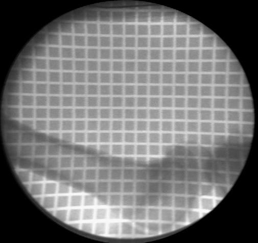
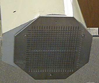
38 Intrinsic Image Calibration Intrinsic imaging parameters (Schreiner et. al.) Image Warping (Checkerboard Based Method) 1/16 4/16 3/16 4/16 Top View Side View
39 Step 0: Acquire Image


40 Step 1: Find groove points Find image points corresponding to the centerline of each vertical and horizontal groove
41 Step 2: Fit 5 th order Bernstein Fit least square smooth curve to each vertical and horizontal groove 5 th order Bernstein Polynomial Polynomial Curves k B( a0,, a5; v) = ak ( 1 v) v k = 0 k k
42 Step 3: Dewarp Employ a two pass scan line algorithm to dewarp the image
43 Advantages Fast 2 seconds on Pentium II 400 Robust works well even with overlaid objects Sub-pixel Accuracy mean error 0.12 mm on the central area Does not completely obscure the image trades off image contrast depth for image area
44 Two Plane Method Plane 1 pattern Plane 2 pattern E.g., Lavallee E.g., Helm
45 Two Plane Method Plane 1 pattern Plane 2 pattern Given q = a point in image coordinates, determine the points f f The desired ray in space passes through and * 1 * 2 f = the point on grid 1 corresponding to = the point on grid 2 corresponding to * 2. f * 1 q q

46 Photos: Sofamor Danek
47 Interpolation Ubiquitous throughout CIS research and applications Many techniques and methods Here are a few more notes Microsoft PowerPoint Presentation
48 Two plane calibration Again, the essential problem is to determine the coordinates in the two planes at which the source-to-detector ray passes through the plane. Many methods for this. E.g., Find the four surrounding bead locations on each plane and use bilinear interpolation Fit a general spline model for the distortion on each plane and then directly interpolate
Calibration. Reality. Error. Measuring device. Model of Reality Fall 2001 Copyright R. H. Taylor 1999, 2001
 Calibration Calibrate (vt) : 1. to determine the caliber of (as a thermometer tube); 2. to determine, rectify, or mark the gradations of (as a thermometer tube); 3. to standardize (as a measuring instrument)
Calibration of a rotating multi-beam Lidar
 The 2010 IEEE/RSJ International Conference on Intelligent Robots and Systems October 18-22, 2010, Taipei, Taiwan Calibration of a rotating multi-beam Lidar Naveed Muhammad 1,2 and Simon Lacroix 1,2 Abstract
Blacksburg, VA July 24 th 30 th, 2010 Georeferencing images and scanned maps Page 1. Georeference
 George McLeod Prepared by: With support from: NSF DUE-0903270 in partnership with: Geospatial Technician Education Through Virginia s Community Colleges (GTEVCC) Georeference The process of defining how
Computer Vision. Coordinates. Prof. Flávio Cardeal DECOM / CEFET- MG.
 Computer Vision Coordinates Prof. Flávio Cardeal DECOM / CEFET- MG cardeal@decom.cefetmg.br Abstract This lecture discusses world coordinates and homogeneous coordinates, as well as provides an overview
CSCI 5980: Assignment #3 Homography
 Submission Assignment due: Feb 23 Individual assignment. Write-up submission format: a single PDF up to 3 pages (more than 3 page assignment will be automatically returned.). Code and data. Submission
Project Title: Welding Machine Monitoring System Phase II. Name of PI: Prof. Kenneth K.M. LAM (EIE) Progress / Achievement: (with photos, if any)
 Progress / Achievement: (with photos, if any)") Address: Hong Kong Polytechnic University, Phase 8, Hung Hom, Kowloon, Hong Kong. Telephone: (852) 3400 8441 Email: cnerc.steel@polyu.edu.hk Website: https://www.polyu.edu.hk/cnerc-steel/ Project Title:
Address: Hong Kong Polytechnic University, Phase 8, Hung Hom, Kowloon, Hong Kong. Telephone: (852) 3400 8441 Email: cnerc.steel@polyu.edu.hk Website: https://www.polyu.edu.hk/cnerc-steel/ Project Title:
GEOG 4110/5100 Advanced Remote Sensing Lecture 4
 GEOG 4110/5100 Advanced Remote Sensing Lecture 4 Geometric Distortion Relevant Reading: Richards, Sections 2.11-2.17 Geometric Distortion Geometric Distortion: Errors in image geometry, (location, dimensions,
Subpixel Corner Detection Using Spatial Moment 1)
") Vol.31, No.5 ACTA AUTOMATICA SINICA September, 25 Subpixel Corner Detection Using Spatial Moment 1) WANG She-Yang SONG Shen-Min QIANG Wen-Yi CHEN Xing-Lin (Department of Control Engineering, Harbin Institute
Vol.31, No.5 ACTA AUTOMATICA SINICA September, 25 Subpixel Corner Detection Using Spatial Moment 1) WANG She-Yang SONG Shen-Min QIANG Wen-Yi CHEN Xing-Lin (Department of Control Engineering, Harbin Institute
Chapter 18. Geometric Operations
 Chapter 18 Geometric Operations To this point, the image processing operations have computed the gray value (digital count) of the output image pixel based on the gray values of one or more input pixels;
Operation Trajectory Control of Industrial Robots Based on Motion Simulation
 Operation Trajectory Control of Industrial Robots Based on Motion Simulation Chengyi Xu 1,2, Ying Liu 1,*, Enzhang Jiao 1, Jian Cao 2, Yi Xiao 2 1 College of Mechanical and Electronic Engineering, Nanjing
An Automated Image-based Method for Multi-Leaf Collimator Positioning Verification in Intensity Modulated Radiation Therapy
 An Automated Image-based Method for Multi-Leaf Collimator Positioning Verification in Intensity Modulated Radiation Therapy Chenyang Xu 1, Siemens Corporate Research, Inc., Princeton, NJ, USA Xiaolei Huang,
THE ANALYTIC AND NUMERICAL DEFINITION OF THE GEOMETRY OF THE BRITISH MUSEUM GREAT COURT ROOF
 Williams, C.J.K. 2001 The analytic and numerical definition of the geometry of the British Museum Great THE ANALYTIC AND NUMERICAL DEFINITION OF THE GEOMETRY OF THE BRITISH MUSEUM GREAT COURT ROOF Chris
Georeferencing & Spatial Adjustment
 Georeferencing & Spatial Adjustment Aligning Raster and Vector Data to the Real World Rotation Differential Scaling Distortion Skew Translation 1 The Problem How are geographically unregistered data, either
Robust and Accurate Detection of Object Orientation and ID without Color Segmentation
 0 Robust and Accurate Detection of Object Orientation and ID without Color Segmentation Hironobu Fujiyoshi, Tomoyuki Nagahashi and Shoichi Shimizu Chubu University Japan Open Access Database www.i-techonline.com
To graph the point (r, θ), simply go out r units along the initial ray, then rotate through the angle θ. The point (1, 5π 6
, simply go out r units along the initial ray, then rotate through the angle θ. The point (1, 5π 6") Polar Coordinates Any point in the plane can be described by the Cartesian coordinates (x, y), where x and y are measured along the corresponding axes. However, this is not the only way to represent points
Polar Coordinates Any point in the plane can be described by the Cartesian coordinates (x, y), where x and y are measured along the corresponding axes. However, this is not the only way to represent points
Assessing Accuracy Factors in Deformable 2D/3D Medical Image Registration Using a Statistical Pelvis Model
 Assessing Accuracy Factors in Deformable 2D/3D Medical Image Registration Using a Statistical Pelvis Model Jianhua Yao National Institute of Health Bethesda, MD USA jyao@cc.nih.gov Russell Taylor The Johns
Robot mechanics and kinematics
 University of Pisa Master of Science in Computer Science Course of Robotics (ROB) A.Y. 2016/17 cecilia.laschi@santannapisa.it http://didawiki.cli.di.unipi.it/doku.php/magistraleinformatica/rob/start Robot
ENGN2911I: 3D Photography and Geometry Processing Assignment 1: 3D Photography using Planar Shadows
 ENGN2911I: 3D Photography and Geometry Processing Assignment 1: 3D Photography using Planar Shadows Instructor: Gabriel Taubin Assignment written by: Douglas Lanman 29 January 2009 Figure 1: 3D Photography
Georeferencing & Spatial Adjustment 2/13/2018
 Georeferencing & Spatial Adjustment The Problem Aligning Raster and Vector Data to the Real World How are geographically unregistered data, either raster or vector, made to align with data that exist in
Optimized Design of 3D Laser Triangulation Systems
 The Scan Principle of 3D Laser Triangulation Triangulation Geometry Example of Setup Z Y X Target as seen from the Camera Sensor Image of Laser Line The Scan Principle of 3D Laser Triangulation Detektion
Flexible Calibration of a Portable Structured Light System through Surface Plane
 Vol. 34, No. 11 ACTA AUTOMATICA SINICA November, 2008 Flexible Calibration of a Portable Structured Light System through Surface Plane GAO Wei 1 WANG Liang 1 HU Zhan-Yi 1 Abstract For a portable structured
The Problem. Georeferencing & Spatial Adjustment. Nature Of The Problem: For Example: Georeferencing & Spatial Adjustment 9/20/2016
 Georeferencing & Spatial Adjustment Aligning Raster and Vector Data to the Real World The Problem How are geographically unregistered data, either raster or vector, made to align with data that exist in
Robot Vision: Camera calibration
 Robot Vision: Camera calibration Ass.Prof. Friedrich Fraundorfer SS 201 1 Outline Camera calibration Cameras with lenses Properties of real lenses (distortions, focal length, field-of-view) Calibration
Motion Control (wheeled robots)
") Motion Control (wheeled robots) Requirements for Motion Control Kinematic / dynamic model of the robot Model of the interaction between the wheel and the ground Definition of required motion -> speed control,
Motion Control (wheeled robots) Requirements for Motion Control Kinematic / dynamic model of the robot Model of the interaction between the wheel and the ground Definition of required motion -> speed control,
CHAPTER 3 DISPARITY AND DEPTH MAP COMPUTATION
 CHAPTER 3 DISPARITY AND DEPTH MAP COMPUTATION In this chapter we will discuss the process of disparity computation. It plays an important role in our caricature system because all 3D coordinates of nodes
Robot mechanics and kinematics
 University of Pisa Master of Science in Computer Science Course of Robotics (ROB) A.Y. 2017/18 cecilia.laschi@santannapisa.it http://didawiki.cli.di.unipi.it/doku.php/magistraleinformatica/rob/start Robot
Visual Recognition: Image Formation
 Visual Recognition: Image Formation Raquel Urtasun TTI Chicago Jan 5, 2012 Raquel Urtasun (TTI-C) Visual Recognition Jan 5, 2012 1 / 61 Today s lecture... Fundamentals of image formation You should know
Inverse Kinematics. Given a desired position (p) & orientation (R) of the end-effector
 & orientation (R) of the end-effector") Inverse Kinematics Given a desired position (p) & orientation (R) of the end-effector q ( q, q, q ) 1 2 n Find the joint variables which can bring the robot the desired configuration z y x 1 The Inverse
Inverse Kinematics Given a desired position (p) & orientation (R) of the end-effector q ( q, q, q ) 1 2 n Find the joint variables which can bring the robot the desired configuration z y x 1 The Inverse
DD2429 Computational Photography :00-19:00
 . Examination: DD2429 Computational Photography 202-0-8 4:00-9:00 Each problem gives max 5 points. In order to pass you need about 0-5 points. You are allowed to use the lecture notes and standard list
A Robust Two Feature Points Based Depth Estimation Method 1)
") Vol.31, No.5 ACTA AUTOMATICA SINICA September, 2005 A Robust Two Feature Points Based Depth Estimation Method 1) ZHONG Zhi-Guang YI Jian-Qiang ZHAO Dong-Bin (Laboratory of Complex Systems and Intelligence
Vol.31, No.5 ACTA AUTOMATICA SINICA September, 2005 A Robust Two Feature Points Based Depth Estimation Method 1) ZHONG Zhi-Guang YI Jian-Qiang ZHAO Dong-Bin (Laboratory of Complex Systems and Intelligence
Creating a distortion characterisation dataset for visual band cameras using fiducial markers.
 Creating a distortion characterisation dataset for visual band cameras using fiducial markers. Robert Jermy Council for Scientific and Industrial Research Email: rjermy@csir.co.za Jason de Villiers Council
Structured Light. Tobias Nöll Thanks to Marc Pollefeys, David Nister and David Lowe
 Structured Light Tobias Nöll tobias.noell@dfki.de Thanks to Marc Pollefeys, David Nister and David Lowe Introduction Previous lecture: Dense reconstruction Dense matching of non-feature pixels Patch-based
Image warping , , Computational Photography Fall 2017, Lecture 10
 Image warping http://graphics.cs.cmu.edu/courses/15-463 15-463, 15-663, 15-862 Computational Photography Fall 2017, Lecture 10 Course announcements Second make-up lecture on Friday, October 6 th, noon-1:30
CALIBRATION BETWEEN DEPTH AND COLOR SENSORS FOR COMMODITY DEPTH CAMERAS. Cha Zhang and Zhengyou Zhang
 CALIBRATION BETWEEN DEPTH AND COLOR SENSORS FOR COMMODITY DEPTH CAMERAS Cha Zhang and Zhengyou Zhang Communication and Collaboration Systems Group, Microsoft Research {chazhang, zhang}@microsoft.com ABSTRACT
Issues with Curve Detection Grouping (e.g., the Canny hysteresis thresholding procedure) Model tting They can be performed sequentially or simultaneou
 Model tting They can be performed sequentially or simultaneou") an edge image, nd line or curve segments present Given the image. in Line and Curves Detection 1 Issues with Curve Detection Grouping (e.g., the Canny hysteresis thresholding procedure) Model tting They
an edge image, nd line or curve segments present Given the image. in Line and Curves Detection 1 Issues with Curve Detection Grouping (e.g., the Canny hysteresis thresholding procedure) Model tting They
To graph the point (r, θ), simply go out r units along the initial ray, then rotate through the angle θ. The point (1, 5π 6. ) is graphed below:
, simply go out r units along the initial ray, then rotate through the angle θ. The point (1, 5π 6. ) is graphed below:") Polar Coordinates Any point in the plane can be described by the Cartesian coordinates (x, y), where x and y are measured along the corresponding axes. However, this is not the only way to represent points
Polar Coordinates Any point in the plane can be described by the Cartesian coordinates (x, y), where x and y are measured along the corresponding axes. However, this is not the only way to represent points
ROBUST LINE-BASED CALIBRATION OF LENS DISTORTION FROM A SINGLE VIEW
 ROBUST LINE-BASED CALIBRATION OF LENS DISTORTION FROM A SINGLE VIEW Thorsten Thormählen, Hellward Broszio, Ingolf Wassermann thormae@tnt.uni-hannover.de University of Hannover, Information Technology Laboratory,
Transformations. Ed Angel Professor of Computer Science, Electrical and Computer Engineering, and Media Arts University of New Mexico
 Transformations Ed Angel Professor of Computer Science, Electrical and Computer Engineering, and Media Arts University of New Mexico Angel: Interactive Computer Graphics 4E Addison-Wesley 25 1 Objectives
The Problem. Georeferencing & Spatial Adjustment. Nature of the problem: For Example: Georeferencing & Spatial Adjustment 2/4/2014
 Georeferencing & Spatial Adjustment Aligning Raster and Vector Data to a GIS The Problem How are geographically unregistered data, either raster or vector, made to align with data that exist in geographical
Forward kinematics and Denavit Hartenburg convention
 Forward kinematics and Denavit Hartenburg convention Prof. Enver Tatlicioglu Department of Electrical & Electronics Engineering Izmir Institute of Technology Chapter 5 Dr. Tatlicioglu (EEE@IYTE) EE463
Calibration of a rotating multi-beam Lidar
 Calibration of a rotating multi-beam Lidar Naveed Muhammad 1,2 and Simon Lacroix 1,2 Abstract This paper presents a technique for the calibration of multi-beam laser scanners. The technique is based on
Robot Geometry and Kinematics
 CIS 68/MEAM 50 Robot Geometr and Kinematics CIS 68/MEAM 50 Outline Industrial (conventional) robot arms Basic definitions for understanding -D geometr, kinematics Eamples Classification b geometr Relationship
Binocular Stereo Vision. System 6 Introduction Is there a Wedge in this 3D scene?
 System 6 Introduction Is there a Wedge in this 3D scene? Binocular Stereo Vision Data a stereo pair of images! Given two 2D images of an object, how can we reconstruct 3D awareness of it? AV: 3D recognition
A Simulation Study and Experimental Verification of Hand-Eye-Calibration using Monocular X-Ray
 A Simulation Study and Experimental Verification of Hand-Eye-Calibration using Monocular X-Ray Petra Dorn, Peter Fischer,, Holger Mönnich, Philip Mewes, Muhammad Asim Khalil, Abhinav Gulhar, Andreas Maier
We can conclude that if f is differentiable in an interval containing a, then. f(x) L(x) = f(a) + f (a)(x a).
 L(x) = f(a) + f (a)(x a).") = sin( x) = 8 Lecture :Linear Approximations and Differentials Consider a point on a smooth curve y = f(x), say P = (a, f(a)), If we draw a tangent line to the curve at the point P, we can see from the
= sin( x) = 8 Lecture :Linear Approximations and Differentials Consider a point on a smooth curve y = f(x), say P = (a, f(a)), If we draw a tangent line to the curve at the point P, we can see from the
University of Technology Building & Construction Department / Remote Sensing & GIS lecture
 5. Corrections 5.1 Introduction 5.2 Radiometric Correction 5.3 Geometric corrections 5.3.1 Systematic distortions 5.3.2 Nonsystematic distortions 5.4 Image Rectification 5.5 Ground Control Points (GCPs)
DTU M.SC. - COURSE EXAM Revised Edition
 Written test, 16 th of December 1999. Course name : 04250 - Digital Image Analysis Aids allowed : All usual aids Weighting : All questions are equally weighed. Name :...................................................
Concept of Curve Fitting Difference with Interpolation
 Curve Fitting Content Concept of Curve Fitting Difference with Interpolation Estimation of Linear Parameters by Least Squares Curve Fitting by Polynomial Least Squares Estimation of Non-linear Parameters
Intrinsic and Extrinsic Camera Parameter Estimation with Zoomable Camera for Augmented Reality
 Intrinsic and Extrinsic Camera Parameter Estimation with Zoomable Camera for Augmented Reality Kazuya Okada, Takafumi Taketomi, Goshiro Yamamoto, Jun Miyazaki, Hirokazu Kato Nara Institute of Science and
Tracked surgical drill calibration
 Tracked surgical drill calibration An acetabular fracture is a break in the socket portion of the "ball-and-socket" hip joint. The majority of acetabular fractures are caused by some type of highenergy
Towards full-body X-ray images
 Towards full-body X-ray images Christoph Luckner 1,2, Thomas Mertelmeier 2, Andreas Maier 1, Ludwig Ritschl 2 1 Pattern Recognition Lab, FAU Erlangen-Nuernberg 2 Siemens Healthcare GmbH, Forchheim christoph.luckner@fau.de
Volumetric Operations with Surface Margins
 MITSUBISHI ELECTRIC RESEARCH LABORATORIES http://www.merl.com Volumetric Operations with Surface Margins Christopher R. Wren Yuri A. Ivanov TR-2001-47 January 2002 Abstract Cheap cameras and fast processors
CHAPTER 4 RAY COMPUTATION. 4.1 Normal Computation
 CHAPTER 4 RAY COMPUTATION Ray computation is the second stage of the ray tracing procedure and is composed of two steps. First, the normal to the current wavefront is computed. Then the intersection of
Capture and Dewarping of Page Spreads with a Handheld Compact 3D Camera
 Capture and Dewarping of Page Spreads with a Handheld Compact 3D Camera Michael P. Cutter University of California at Santa Cruz Baskin School of Engineering (Computer Engineering department) Santa Cruz,
Restoring Warped Document Image Based on Text Line Correction
 Restoring Warped Document Image Based on Text Line Correction * Dep. of Electrical Engineering Tamkang University, New Taipei, Taiwan, R.O.C *Correspondending Author: hsieh@ee.tku.edu.tw Abstract Document
3D Imaging from Video and Planar Radiography
 3D Imaging from Video and Planar Radiography Julien Pansiot and Edmond Boyer Morpheo, Inria Grenoble Rhône-Alpes, France International Conference on Medical Image Computing and Computer Assisted Intervention
Adding vectors. Let s consider some vectors to be added.
 Vectors Some physical quantities have both size and direction. These physical quantities are represented with vectors. A common example of a physical quantity that is represented with a vector is a force.
Grasping Known Objects with Aldebaran Nao
 CS365 Project Report Grasping Known Objects with Aldebaran Nao By: Ashu Gupta( ashug@iitk.ac.in) Mohd. Dawood( mdawood@iitk.ac.in) Department of Computer Science and Engineering IIT Kanpur Mentor: Prof.
Rectification and Distortion Correction
 Rectification and Distortion Correction Hagen Spies March 12, 2003 Computer Vision Laboratory Department of Electrical Engineering Linköping University, Sweden Contents Distortion Correction Rectification
Camera Model and Calibration
 Camera Model and Calibration Lecture-10 Camera Calibration Determine extrinsic and intrinsic parameters of camera Extrinsic 3D location and orientation of camera Intrinsic Focal length The size of the
Project 2 due today Project 3 out today. Readings Szeliski, Chapter 10 (through 10.5)
") Announcements Stereo Project 2 due today Project 3 out today Single image stereogram, by Niklas Een Readings Szeliski, Chapter 10 (through 10.5) Public Library, Stereoscopic Looking Room, Chicago, by Phillips,
Announcements Stereo Project 2 due today Project 3 out today Single image stereogram, by Niklas Een Readings Szeliski, Chapter 10 (through 10.5) Public Library, Stereoscopic Looking Room, Chicago, by Phillips,
Midterm Exam Solutions
 Midterm Exam Solutions Computer Vision (J. Košecká) October 27, 2009 HONOR SYSTEM: This examination is strictly individual. You are not allowed to talk, discuss, exchange solutions, etc., with other fellow
Introduction to Homogeneous coordinates
 Last class we considered smooth translations and rotations of the camera coordinate system and the resulting motions of points in the image projection plane. These two transformations were expressed mathematically
Computer Vision I - Appearance-based Matching and Projective Geometry
 Computer Vision I - Appearance-based Matching and Projective Geometry Carsten Rother 05/11/2015 Computer Vision I: Image Formation Process Roadmap for next four lectures Computer Vision I: Image Formation
3D Guide Wire Navigation from Single Plane Fluoroscopic Images in Abdominal Catheterizations
 3D Guide Wire Navigation from Single Plane Fluoroscopic Images in Abdominal Catheterizations Martin Groher 2, Frederik Bender 1, Ali Khamene 3, Wolfgang Wein 3, Tim Hauke Heibel 2, Nassir Navab 2 1 Siemens
Visual Odometry. Features, Tracking, Essential Matrix, and RANSAC. Stephan Weiss Computer Vision Group NASA-JPL / CalTech
 Visual Odometry Features, Tracking, Essential Matrix, and RANSAC Stephan Weiss Computer Vision Group NASA-JPL / CalTech Stephan.Weiss@ieee.org (c) 2013. Government sponsorship acknowledged. Outline The
calibrated coordinates Linear transformation pixel coordinates
 1 calibrated coordinates Linear transformation pixel coordinates 2 Calibration with a rig Uncalibrated epipolar geometry Ambiguities in image formation Stratified reconstruction Autocalibration with partial
Surfaces, meshes, and topology
 Surfaces from Point Samples Surfaces, meshes, and topology A surface is a 2-manifold embedded in 3- dimensional Euclidean space Such surfaces are often approximated by triangle meshes 2 1 Triangle mesh
Stereo imaging ideal geometry
 Stereo imaging ideal geometry (X,Y,Z) Z f (x L,y L ) f (x R,y R ) Optical axes are parallel Optical axes separated by baseline, b. Line connecting lens centers is perpendicular to the optical axis, and
The diagram above shows a sketch of the curve C with parametric equations
 1. The diagram above shows a sketch of the curve C with parametric equations x = 5t 4, y = t(9 t ) The curve C cuts the x-axis at the points A and B. (a) Find the x-coordinate at the point A and the x-coordinate
CSE 490R P3 - Model Learning and MPPI Due date: Sunday, Feb 28-11:59 PM
 CSE 490R P3 - Model Learning and MPPI Due date: Sunday, Feb 28-11:59 PM 1 Introduction In this homework, we revisit the concept of local control for robot navigation, as well as integrate our local controller
3-D D Euclidean Space - Vectors
 3-D D Euclidean Space - Vectors Rigid Body Motion and Image Formation A free vector is defined by a pair of points : Jana Kosecka http://cs.gmu.edu/~kosecka/cs682.html Coordinates of the vector : 3D Rotation
Chapter 10 Homework: Parametric Equations and Polar Coordinates
 Chapter 1 Homework: Parametric Equations and Polar Coordinates Name Homework 1.2 1. Consider the parametric equations x = t and y = 3 t. a. Construct a table of values for t =, 1, 2, 3, and 4 b. Plot the
Improving Vision-Based Distance Measurements using Reference Objects
 Improving Vision-Based Distance Measurements using Reference Objects Matthias Jüngel, Heinrich Mellmann, and Michael Spranger Humboldt-Universität zu Berlin, Künstliche Intelligenz Unter den Linden 6,
EECS 4330/7330 Introduction to Mechatronics and Robotic Vision, Fall Lab 1. Camera Calibration
 1 Lab 1 Camera Calibration Objective In this experiment, students will use stereo cameras, an image acquisition program and camera calibration algorithms to achieve the following goals: 1. Develop a procedure
More Mosaic Madness. CS194: Image Manipulation & Computational Photography. Steve Seitz and Rick Szeliski. Jeffrey Martin (jeffrey-martin.
 More Mosaic Madness Jeffrey Martin (jeffrey-martin.com) CS194: Image Manipulation & Computational Photography with a lot of slides stolen from Alexei Efros, UC Berkeley, Fall 2018 Steve Seitz and Rick
Multi-slice CT Image Reconstruction Jiang Hsieh, Ph.D.
 Multi-slice CT Image Reconstruction Jiang Hsieh, Ph.D. Applied Science Laboratory, GE Healthcare Technologies 1 Image Generation Reconstruction of images from projections. textbook reconstruction advanced
Thickness of the standard piece: 10 mm The most important calibration data are engraved in the side face of the specimen.
 Rk standard The surface of this standard is made up of turned grooves (average curve radius approx. 150 mm). The surface consists of a hardened nickel coating (> 900HV1) on a base body made from brass.
COS429: COMPUTER VISON CAMERAS AND PROJECTIONS (2 lectures)
") COS429: COMPUTER VISON CMERS ND PROJECTIONS (2 lectures) Pinhole cameras Camera with lenses Sensing nalytical Euclidean geometry The intrinsic parameters of a camera The extrinsic parameters of a camera
COS429: COMPUTER VISON CMERS ND PROJECTIONS (2 lectures) Pinhole cameras Camera with lenses Sensing nalytical Euclidean geometry The intrinsic parameters of a camera The extrinsic parameters of a camera
Outline. ETN-FPI Training School on Plenoptic Sensing
 Outline Introduction Part I: Basics of Mathematical Optimization Linear Least Squares Nonlinear Optimization Part II: Basics of Computer Vision Camera Model Multi-Camera Model Multi-Camera Calibration
Multi-view Surface Inspection Using a Rotating Table
 https://doi.org/10.2352/issn.2470-1173.2018.09.iriacv-278 2018, Society for Imaging Science and Technology Multi-view Surface Inspection Using a Rotating Table Tomoya Kaichi, Shohei Mori, Hideo Saito,
Homework Assignment /645 Fall Instructions and Score Sheet (hand in with answers)
") Homework Assignment 3 600.445/645 Fall 2018 Instructions and Score Sheet (hand in with answers) Name Email Other contact information (optional) Signature (required) I have followed the rules in completing
Homework Assignment 3 600.445/645 Fall 2018 Instructions and Score Sheet (hand in with answers) Name Email Other contact information (optional) Signature (required) I have followed the rules in completing
A Tool for Kinematic Error Analysis of Robots/Active Vision Systems
 A Tool for Kinematic Error Analysis of Robots/Active Vision Systems Kanglin Xu and George F. Luger Department of Computer Science University of New Mexico Albuquerque, NM 87131 {klxu,luger}@cs.unm.edu
Today. Stereo (two view) reconstruction. Multiview geometry. Today. Multiview geometry. Computational Photography
 reconstruction. Multiview geometry. Today. Multiview geometry. Computational Photography") Computational Photography Matthias Zwicker University of Bern Fall 2009 Today From 2D to 3D using multiple views Introduction Geometry of two views Stereo matching Other applications Multiview geometry
Computational Photography Matthias Zwicker University of Bern Fall 2009 Today From 2D to 3D using multiple views Introduction Geometry of two views Stereo matching Other applications Multiview geometry
CALCULATING TRANSFORMATIONS OF KINEMATIC CHAINS USING HOMOGENEOUS COORDINATES
 CALCULATING TRANSFORMATIONS OF KINEMATIC CHAINS USING HOMOGENEOUS COORDINATES YINGYING REN Abstract. In this paper, the applications of homogeneous coordinates are discussed to obtain an efficient model
Self-Calibration of a Camera Equipped SCORBOT ER-4u Robot
 Self-Calibration of a Camera Equipped SCORBOT ER-4u Robot Gossaye Mekonnen Alemu and Sanjeev Kumar Department of Mathematics IIT Roorkee Roorkee-247 667, India gossayemekonnen@gmail.com malikfma@iitr.ac.in
2D Image Transforms Computer Vision (Kris Kitani) Carnegie Mellon University
 Carnegie Mellon University") 2D Image Transforms 16-385 Computer Vision (Kris Kitani) Carnegie Mellon University Extract features from an image what do we do next? Feature matching (object recognition, 3D reconstruction, augmented
2D Image Transforms 16-385 Computer Vision (Kris Kitani) Carnegie Mellon University Extract features from an image what do we do next? Feature matching (object recognition, 3D reconstruction, augmented
Math 11 Fall 2016 Section 1 Monday, October 17, 2016
 Math 11 Fall 16 Section 1 Monday, October 17, 16 First, some important points from the last class: f(x, y, z) dv, the integral (with respect to volume) of f over the three-dimensional region, is a triple
Computer Vision Projective Geometry and Calibration. Pinhole cameras
 Computer Vision Projective Geometry and Calibration Professor Hager http://www.cs.jhu.edu/~hager Jason Corso http://www.cs.jhu.edu/~jcorso. Pinhole cameras Abstract camera model - box with a small hole
GBT Commissioning Memo 11: Plate Scale and pointing effects of subreflector positioning at 2 GHz.
 GBT Commissioning Memo 11: Plate Scale and pointing effects of subreflector positioning at 2 GHz. Keywords: low frequency Gregorian, plate scale, focus tracking, pointing. N. VanWey, F. Ghigo, R. Maddalena,
EMRP JRP IND62 TIM: Use of on-board metrology systems for area-scanning on machine tools
 EMRP JRP IND62 TIM: Use of on-board metrology systems for area-scanning on machine tools Author: Co-authors: doc. Ing. Vít Zelený, CSc. doc. Ing. Ivana Linkeová, Ph.D. Ing. Jakub Sýkora Pavel Skalník Jaromír
3D Geometry and Camera Calibration
 3D Geometr and Camera Calibration 3D Coordinate Sstems Right-handed vs. left-handed 2D Coordinate Sstems ais up vs. ais down Origin at center vs. corner Will often write (u, v) for image coordinates v
Robotic Arm Motion for Verifying Signatures
 Robotic Arm Motion for Verifying Signatures Moises Diaz 1 Miguel A. Ferrer 2 Jose J. Quintana 2 1 Universidad del Atlantico Medio, Spain 2 Instituto para el Desarrollo Tecnológico y la Innovación en Comunicaciones
Computer Vision I. Dense Stereo Correspondences. Anita Sellent 1/15/16
 Computer Vision I Dense Stereo Correspondences Anita Sellent Stereo Two Cameras Overlapping field of view Known transformation between cameras From disparity compute depth [ Bradski, Kaehler: Learning
Computer Graphics 7: Viewing in 3-D
 Computer Graphics 7: Viewing in 3-D In today s lecture we are going to have a look at: Transformations in 3-D How do transformations in 3-D work? Contents 3-D homogeneous coordinates and matrix based transformations
Information page for written examinations at Linköping University TER2
 Information page for written examinations at Linköping University Examination date 2016-08-19 Room (1) TER2 Time 8-12 Course code Exam code Course name Exam name Department Number of questions in the examination
Interpolation by Spline Functions
 Interpolation by Spline Functions Com S 477/577 Sep 0 007 High-degree polynomials tend to have large oscillations which are not the characteristics of the original data. To yield smooth interpolating curves
Camera calibration for miniature, low-cost, wide-angle imaging systems
 Camera calibration for miniature, low-cost, wide-angle imaging systems Oliver Frank, Roman Katz, Christel-Loic Tisse and Hugh Durrant-Whyte ARC Centre of Excellence for Autonomous Systems University of
Camera Calibration. Schedule. Jesus J Caban. Note: You have until next Monday to let me know. ! Today:! Camera calibration
 Camera Calibration Jesus J Caban Schedule! Today:! Camera calibration! Wednesday:! Lecture: Motion & Optical Flow! Monday:! Lecture: Medical Imaging! Final presentations:! Nov 29 th : W. Griffin! Dec 1
FLAP P6.2 Rays and geometrical optics COPYRIGHT 1998 THE OPEN UNIVERSITY S570 V1.1
 F1 The ray approximation in optics assumes that light travels from one point to another along a narrow path called a ray that may be represented by a directed line (i.e. a line with an arrow on it). In