INSTALLATION INSTRUCTION
|
|
|
- Curtis Derek Hall
- 6 years ago
- Views:
Transcription

1 INSTALLATION INSTRUCTION EX30 Infrared Imager MAN-30-06
2 IMPORTANT SAFETY INSTRUCTIONS 1. Read these instructions. 2. Keep this instruction. 3. Heed all warnings. 4. Follow all instructions. 5. Do not use this apparatus near water. 6. Clean only with dry cloth. 7. Do not block any ventilation openings. Install in accordance with manufacturer instructions. 8. Do not install near any heat sources such as radiators, heat registers, stoves or other apparatus (including amplifiers) that produce heat. 9. Do not defeat the safety purpose of the polarized or grounding-type plug. A polarized plug has two blades with one wider than the other. A grounding type plug has two blades and a third grounding prong. The wide blade or the third prong is provided for your safety. If the provided plug does not fit into your outlet, consult an electrician for replacement of the obsolete outlet
3 10. Protect the power cord from being walked on or pinched particularly at plugs, convenience receptacles, and the power where they exit from the apparatus. 11. Only use attachments/accessories specified by the manufacturer. 12. Use only with the cart, stand, tripod, bracket, or table specified by the manufacturer, or sold with the apparatus. When a cart is used, use caution when moving the cart/apparatus combination to avoid injury from tip-over. 13. Unplug this apparatus during lightning storms or when unused for long periods of time. 14. Refer all servicing to qualified service personnel. Servicing is required when the apparatus has been damaged in a way, such as power-supply cord or plug is damaged, liquid has been spilled or objects have fallen into the apparatus, the apparatus has been exposed to rain or moisture, does not operate normally, or has been dropped

4 IMPORTANT For best results, please read this Instruction Booklet prior to installing the EX30 Infrared Imager. WARNING! CSA Certified / UL Listed CLASS 2 power adaptors must be used in order to comply with electrical safety Only qualified personnel shall install any EXTREME CCTV surveillance camera. EXTREME CCTV will not be responsible for injuries or damages resulting from the improper installation or use of any equipment sold by EXTREME CCTV, their agents, distributors or dealers
5 NOTE: This equipment has been tested and found to comply with the limits for a digital device, pursuant to part 15 of the FCC rules. These limits are designed to provide reasonable protection against harmful interference in a residential installation. As part of its normal operation this device can generate radio frequency energy and if not installed and used in accordance with the installation manual may cause interference to radio communications. However, there is no guarantee that interference will not occur on a particular installation. If the device does cause interference to radio or television reception the user is encouraged to try to correct the interference by one or more of the following measures: 1) Fit Ferrite beads on all cable to and from the power supply box, within the box walls. 2) Route the composite cable between the camera and the power supply in steel conduit piping over the entire run of the cable up to and including connection to a deep conduit base fitted under the camera and a conduit fitting adaptor in the wall of the PSU box. 3) Contact BOSCH Service Center for further advice
6 INDEX EX30 Infrared Imager PAGE DESCRIPTION... 7 UNPACKING... 8 PARTS LIST... 8 ITEMS REQUIRED FOR INSTALLATION... 8 INITIAL PREPARATIONS... 9 GUIDELINES MOUNTING BRACKET PREPARATION CABLE / BRACKET INSERTION MOUNTING BRACKET ATTACHMENT CAMERA MOUNTING CAMERA LENS ADJUSTMENTS AND SELECTING THE WINDOW LED ARRAY - POWER ADJUSTMENTS OSD ADJUSTMENT OSD MENU CAMERA RE-ASSEMBLY TROUBLESHOOTING GUIDE -CAMERA TROUBLESHOOTING GUIDE LEDs MOUNTING HOLE - DIAGRAM GENERAL SPECIFICATIONS
7 DESCRIPTION The EX30 Infrared Imager consists of an LXR camera and an infrared illuminator. This surveillance system gives optimum performance during daylight conditions and in the pitch black of night. The camera has a Vari Focal lens, and is seamlessly switched by a photocell when light conditions change from day to night, ensuring no loss of image quality. An all-weather housing with tough polycarbonate windows contains all the electronics. Low voltage operation, low power consumption, LED illuminators, thermostat controlled defroster and solid-state CCD technology make this camera very reliable and efficient. A voltage regulator circuit allows for DC or AC operation, and also provides protection from voltage surges, transient spikes, and reverse voltage. See the Light. Get the Picture
8 UNPACKING Care should be taken when unpacking the shipped unit. Check the parts list and confirm all items have been located. Inspect the equipment thoroughly to ensure nothing was damaged in transit. Contact BOSCH Service Center if a problem is noted, see the rear page of this booklet for contact numbers. PARTS LIST (items supplied with unit) - EX30 camera assembly - Installation Instructions booklet - Cardboard box containing one adjustable wall - mounting bracket. - Extra window (80º illumination beam) ITEMS REQUIRED FOR INSTALLATION (not supplied with units) Mounting hardware Mounting tools Camera Power Supply - 8 -
9 INITIAL PREPARATIONS Determine the operating voltage at the installation site. The camera s Voltage Regulator Board accepts both VDC and 12-28VAC input without change to internal connections. Determine the optimum mounting location for the camera. See Section 4, Camera Mounting. All cameras have been tested and pre-focused with telephoto setting as factory default prior to shipment. If any adjustment needed, it is advisable to check the camera s operation before installation. GUIDELINES The installation of the EX30 camera is explained in Sections 1 to 7. It is important that these steps are followed in numerical order. It is also important to follow proper safety guidelines when installing this product
10 1. MOUNTING BRACKET PREPARATION EXMB.028 Mounting Bracket SET SCREW Use the supplied Allen Key to remove the setscrew from the supplied mounting bracket. Separate the two sections of the mounting bracket
11 2. CABLE / BRACKET INSERTION EX30 Camera Carefully feed the Power/BNC cable through both sections of the mounting bracket. Make sure the cable is not kinked, chafed, or split during this procedure

12 3. MOUNTING BRACKET ATTACHMENT Attach the Mounting Bracket to the Camera s Mounting Block using the six bolts supplied with the bracket. Snug the two halves of the bracket together with the Allen head set screw. Tighten the setscrew enough so that the camera can be adjusted for angle. Do not over-tighten. Note the angled part of the mounting bracket faces to the rear of the camera
13 4. CAMERA MOUNTING Warning: this apparatus must be securely attached to the wall or ceiling in accordance with installation instructions. Failure to follow installation instructions ma results in injury/death. Select a suitable location that protects the camera from accidental damage, tampering and environmental conditions exceeding the specifications of the camera to be mounted. Caution: Ensure the selected location is protected from falling objects, accidental contact with moving objects and unintentional interference from personnel. Follow all applicable building codes. The following installation guidelines must be followed: Locate the bracket such that it cannot be easily interfered with, either intentionally or accidentally. Select a smooth, flat mounting surface to ensure proper sealing. The surface must also be capable of supporting the combined weight of the camera and mounting hardware under all expected conditions of vibration and temperature. Secure all cabling
14 Installation should only be performed by skilled personnel Hardware required: For ceiling mount: 1. Mounting Bracket, Model EXMB.029, Qty = 1 2. ¼ x 2 Lag Screws, Qty = 1 3. ¼ Washer, Qty = 1 For wall mount: 1. Mounting Bracket, Model EXMB.028, Qty = 1 2. ¼ x 2 Lag Screws, Qty = 4 Tools required: Drill Stud Finder 5/32 Drill Bit Socket Driver 7/16 Socket Mounting instructions for wall and ceiling mount: Camera is intended to be securely mounted to a wall using mounting bracket model EXMB.028, or to a ceiling using mounting bracket model EXMB.029. Camera has been evaluated for wall mounting using the following wood screws secured into a 2x4 stud under ½ drywall. Wood screws, 1/4 lag, dia Ø1/4, 2 long, 9 TPI, with ½ head. Camera has been evaluated for ceiling
15 mounting using the following wood screws secured into a 2x4 stud under ½ drywall: wood screws with washer, 1/4 lag, dia Ø1/4, 2 long, 9 TPI, with ½ head 16 flat washer. Camera has not been evaluated for safety requirements using other mounting kits. Installation (Ceiling and Wall Mount) Locate stud in the ceiling/wall and mark outside edges of stud. Using ceiling/wall mount bracket as a template, align the mounting hole with the center of the stud. Marking the point on the ceiling/wall in the center of the hole where mounting screw will be positioned. Remove the ceiling/wall mount bracket and using a 5/32 drill bit, drill a pilot hole at the marked point. Align the ceiling/wall mount bracket mounting hole with the hole drilled in the ceiling/wall Using a 7/16 socket and driver, secure the ceiling/wall mount bracket by screwing the 1/4 lag bolt with 1/4 washer securely into the stud. Use additional 1/4 lag bolt and 1/4 washer to secure the remaining mounting holes. Installation is complete

16 5. CAMERA LENS ADJUSTMENTS AND SELECTING THE WINDOW For optimum picture quality, the camera lens should be as close as possible to the inside face of the viewing window, without touching. The camera is pre-focused with telephoto setting as factory default. Follow the steps below if any adjustment needed. Loosen the four bolts from the extrusion. Remove the faceplate, window and the lens foam, set aside. Make sure the photocell is not dislodged. Do proper adjustment as 5.1 Loosen the four bolts
17 Loosen this setscrew for Focus Adjustment Loosen this setscrew for Telephoto or Wide Angle Adjustment 5.1. Vari Focal and Auto-Iris Control Adjustments Loosen the lens set screws for focus/zoom adjustments. The setscrew marked N is used for image focus. The setscrew marked T W is used for telephoto or wide-angle settings. Re-tighten the setscrews after focus adjustments have been completed. Window Selection
18 Telephoto (Factory standard) Wide Use 40º illumination beam Use 80ºillumination beam Use a Neutral Density filter or Infra-Red Pass filter to cover the lens during focusing to simulate low light conditions on scene for correct 24-hour focusing. For camera with varifocal lens, the camera should be focused with the lens iris fully opened to simulate the worst possible depth of field. Using a Neutral Density filter or Infra-Red Pass filter will ensure the iris is fully open for correct setup and adjustment. Note that statement above is applicable only for Day/Night or IR version cameras
19 6. LED ARRAY - POWER ADJUSTMENTS If adjustment is needed, remove the rear cover for access to the LRB. The EX30 needs to be powered-up while making the LED power adjustments. Cover the photocell to turn the LEDs ON (850nm LEDs will have a slight red glow). For photocell On/Off light-level adjustment, rotate VR2. Clockwise is off and counter-clockwise is on. LED Power Adjustment Photocell On/Off Adjustment LED Power and Photocell On/Off Adjustments Adjust the LED power if they are too bright or too dim. For IR power adjustment, rotate VR1. Clockwise is high and counter-clockwise is low

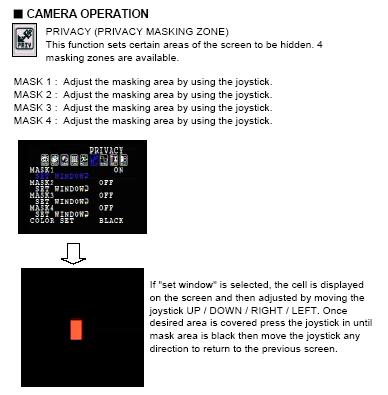
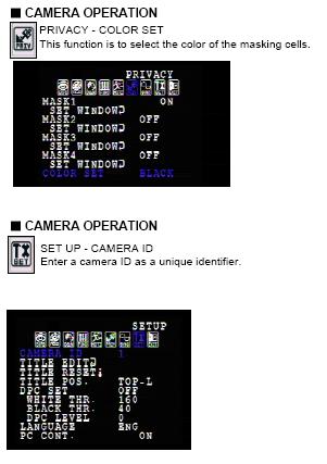
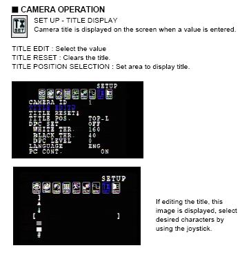
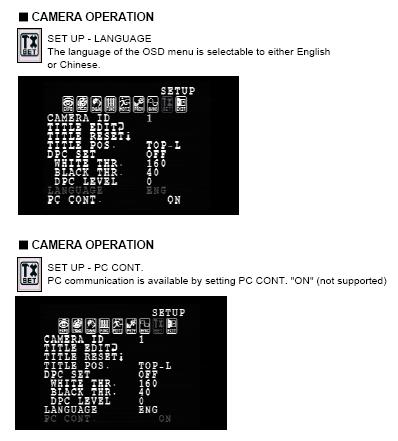
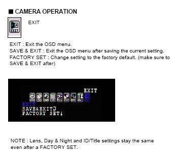
20 7. OSD ADJUSTMENT 1. Open the back cover of EX30 to access the OSD controls. 2. Enter the OSD menu by pressing the joystick button down. 3. Follow the instructions below to make camera adjustments

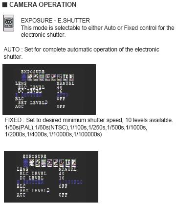
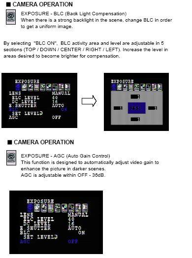
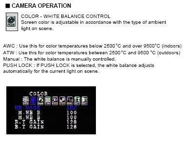
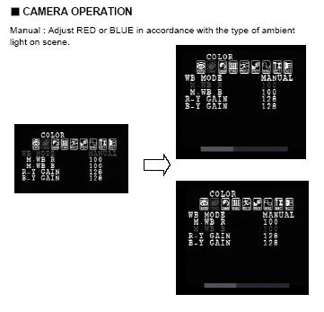
21 8. OSD MENU
22 Note The following default settings should not be changed: Lens = DC; E.Shutter = Auto
23 - 23 -
24 - 24 -
25 - 25 -
26 - 26 -
27 - 27 -

28 Note The following default setting should not be changed. Day & Night = Auto
29 - 29 -
30 - 30 -
31 - 31 -
32 - 32 -
33 - 33 -
34 - 34 -
35 - 35 -
36 - 36 -
37 - 37 -
38 - 38 -
39 - 39 -
40 9. CAMERA RE-ASSEMBLY Make sure all wires are properly connected, all holes are sealed against moisture penetration, and all mounting screws are tight. Slide the lens foam over the camera lens. Make sure the foam is snug and as close to the faceplate viewing window as possible and the photocell is secure with an unobstructed view. Attach the window, faceplate, and the rear cover to the camera housing. Tighten the four bolts. Tighten the camera s adjustable mounting bracket after the desired viewing angle has been determined. Power-up the camera and check its operation
41 10. TROUBLESHOOTING GUIDE -CAMERA PROBLEM POSSIBLE CAUSE LIKELY SOLUTION No Video 1. Power Supply: - Connections. -Voltage Range Video Connections Check the input power connections at the terminal block, ensuring no wires are loose. The supply range is: 12-28VAC or VDC. Measure the voltage at the terminal block. Determine if the wiring polarity at the Video Connector terminal block is correct. Check BNC connector. If still no video, connect the camera directly to the
42 monitor. Check the video signal. If okay, the problem is with the interconnections. Poor Picture Quality Dim Image Snowy Image Iris closed Poor Video Signal Noisy Power Supply If still no video, contact BOSCH Service Center. See rear page of this manual for contact information. Increase iris level on lens Ensure the video cable is correctly matched and terminated with 75 ohms at each end. Make sure the video cables are of similar types. Check all power
43 Horizontal Scan Lines, Rolling Up or Down Negative, scrambled, or faded image Ground Looping on video cable Low voltage connections. Relocate or replace the power supply. Check the coax cable shield is not touching ground, e.g. at the couplings. An electrically isolated circuit board or isolation transformer may be required. Check voltage at input power cable. Must be >10.5VDC or >12VAC. Video leads reversed connection
44 - 44 -
45 11. TROUBLESHOOTING GUIDE LEDs PROBLEM POSSIBLE SOLUTION Fuse Blows Don t know if LEDS are ON LEDs are not ON LEDs are not turning OFF when sufficient ambient light is present - Check the fuse rating. - Check for shorting between the housing and the input power wires nm LEDs will have a faint red glow when ON. 940nm LEDs are covert. - Aim the LEDs directly at an IR sensitive camera, or use a mirror to see the lights through the EX30 camera, or wait for the LEDs to warm up (two minutes). - Cover the photo sensor to activate power to the LEDs (up to 30 seconds delay for activation). - Adjust the photocell s variable resistor towards the ON position. - Adjust power to the LEDs. - Make sure the photo sensor is not covered or hidden behind any object. - Adjust the photocell s variable resistor towards the OFF position (up to 30 seconds delay). The LEDS will stay ON or OFF if the adjustments are at full turn
46 12. MOUNTING HOLE - DIAGRAM All dimensions expressed in millimeters 1.59 X 3.38 in inches
47 13. GENERAL SPECIFICATIONS Power Consumption: Maximum Current: Input Voltage: Enclosure (housing): Viewing Window: 36W Max. 24VAC 12VDC Aluminum casting Glass Dimensions: 130mm H ( 5.12 ) 134.5mm W ( mm L ( 8.35 ) Operational Temperatures: Weight: C to C 2.2kg (4.9 lbs.) Subject to change without notice
48 Note:
49 Americas Bosch Security Systems, Inc. 850 Greenfield Road Lancaster, Pennsylvania USA Telephone Fax security.sales@us.bosch.com Europe, Middle East, Africa: Bosch Security Systems B.V. P.O. Box JB Eindhoven, Netherlands Phone: Fax: emea.securitysystems@bosch.com Asia Pacific: Bosch Security Systems Pte Ltd. 38C Japan Pemimpin Singapore Phone: Fax: apr.securitysystems@bosch.com Bosch Security Systems., Inc. 2009; Data subject to change with out notice
EX27/EX27N/EX27D All-Weather Cameras
 INSTALLATION INSTRUCTIONS EX27/EX27N/EX27D All-Weather Cameras MAN-27/27N/27D-01 1 IMPORTANT SAFETY INSTRUCTIONS 1. Read these instructions. 2. Keep this instruction. 3. Heed all warnings. 4. Follow all
EX72N Explosion Protected Camera
 Precision Engineered Opto-Electronics INSTALLATION INSTRUCTIONS EX72N Explosion Protected Camera MAN72N-00 IMPORTANT SAFETY INSTRUCTIONS 1. Read these instructions. 2. Keep this instruction. 3. Heed all
EX12LED Infrared LED Illuminator
 Precision Engineered Opto-Electronics INSTALLATION INSTRUCTIONS EX12LED Infrared LED Illuminator MAN-12LED-06 IMPORTANT SAFETY INSTRUCTIONS 1. Read these instructions. 2. Keep this instruction. 3. Heed
EX80/EX82-IP Infrared Imager
 EX80/EX82-IP Infrared Imager EX80/EX82-IP en Installation Manual EX80/82-IP en 1 Important safety instructions Type numbers: NEI-808V04-11, NEI-809V04-11, NEI-808V04-21, NEI-809V04-21 NEI-828V04-11, NEI-829V04-11,
EX49 Conical No-Grip Dome Camera
 INSTALLATION INSTRUCTIONS EX49 Conical No-Grip Dome Camera MAN-49-01 IMPORTANT SAFETY INSTRUCTIONS 1. Read these instructions. 2. Keep this instruction. 3. Heed all warnings. 4. Follow all instructions.
INSTALLATION INSTRUCTIONS EX85 MEGAPIXEL-IP INFRARED IMAGER
 INSTALLATION INSTRUCTIONS EX85 MEGAPIXEL-IP INFRARED IMAGER MAN 85 02 IMPORTANT SAFETY INSTRUCTIONS 1. Read these instructions. 2. Keep this instruction. 3. Heed all warnings. 4. Follow all instructions.
Always there to help you. Register your product and get support at SPA1330. Question? Contact Philips.
 Always there to help you Register your product and get support at www.philips.com/welcome Question? Contact Philips SPA1330 User manual Contents 1 Important 2 Safety 2 Notice 3 English 2 Your multimedia
BS 181 SINGLE CHANNEL POWER SUPPLY USER MANUAL
 BS 181 SINGLE CHANNEL POWER SUPPLY USER MANUAL August 2016 This product is designed and manufactured by: ASL Intercom B.V. Zonnebaan 42 3542 EG Utrecht The Netherlands Phone: +31 (0)30 2411901 Fax: +31
Kogan Bluetooth Karaoke System with Dual Microphones KAKAR2MICA
 Kogan Bluetooth Karaoke System with Dual Microphones KAKAR2MICA K TABLE OF CONTENTS SAFETY & WARNINGS...1 IMPORTANT SAFETY INSTRUCTIONS...1 AC CONNECTION...2 LOCATION OF CONTROLS...3 ASSEMBLY AND CONNECTIONS...4
BS 181 SINGLE CHANNEL POWER SUPPLY USER MANUAL
 BS 181 SINGLE CHANNEL POWER SUPPLY USER MANUAL Issue 2011 ASL Intercom BV DESIGNED & MANUFACTURED BY: ASL Intercom B.V. Zonnebaan 42 3542 EG Utrecht The Netherlands Tel: +31 (0)30 2411901 Fax: +31 (0)30
BS 287 DUAL CHANNEL POWER SUPPLY. User Manual. January 2017 V1.0
 BS 287 DUAL CHANNEL POWER SUPPLY User Manual January 2017 V1.0 Table of contents 1.0 SAFETY INSTRUCTIONS... 3 2.0 GENERAL DESCRIPTION PS 289... 4 3.0 MECHANICAL INSTALLATION... 5 4.0 MAINS POWER & SAFETY
MBE Mounts and Adapters
 MBE Mounts and Adapters MBE Series en Installation Guide MBE Mounts and Adapters Table of Contents en 3 Table of Contents 1 Important safety instructions 4 2 MBE Series Mounts and Adapters 6 2.1 Unpacking
5 B&W Rear View System Camera
 5 B&W Rear View System Camera Instruction Manual MODEL: CA453 www.lorexcctv.com Copyright 2007 LOREX Technology Inc. Thank you for purchasing the Lorex 5 Black & White Rear View System Camera. This system
High Contrast License Plate Capture Camera
 High Contrast License Plate Capture Camera OPERATION MANUAL CLP7550I-001 Thank you for choosing our high quality camera. Before attempting to connect operate this unit, please read and follow these instructions.
High Contrast License Plate Capture Camera
 High Contrast License Plate Capture Camera OPERATION MANUAL CLP5050I-001 Thank you for choosing our high quality camera. Before attempting to connect operate this unit, please read and follow these instructions.
High Contrast License Plate Capture Camera
 High Contrast License Plate Capture Camera OPERATION MANUAL M152-LP751-002 Thank you for choosing our high quality camera. Before attempting to connect or operate this unit, please read and follow these
 POWER + - + + - INPUT 2010 INNOVAGE LLC All Rights Reserved. Project Name: ProjectorS35_IM Designer/Studio: INNOVAGE Revision: SET UP AND INSTALLATION RCA cables generally cannot be connected to a TV (unless
Mini Strip Covert Camera
 Mini Strip Covert Camera Please read this manual thoroughly before use, and keep it handy for future reference. Design and specifications are subject to change without notice. FCC COMPLIANCE STATEMENT
MODEL 805 USER MANUAL
 MODEL 805 USER MANUAL All Rights Reserved Page 1 of 12 UNPACKING & INSPECTION Save all packing materials they are required for returns and warranty service. Inspect the 805 and packing materials for any
HDMI to 3GSDI Converter
 HDMI to 3GSDI Converter EXT-HD-3G-C User Manual Release A2 Important Safety Instructions 1. Read these instructions. 2. Keep these instructions. 3. Heed all warnings. 4. Follow all instructions. 5. Do
USB 2.0 SR. Extender over one CAT-5 Cable. User Manual EXT-USB2.0-SR. Version A1
 USB 2.0 SR Extender over one CAT-5 Cable EXT-USB2.0-SR User Manual Version A1 Important Safety Instructions 1. Read these instructions. 2. Keep these instructions. 3. Heed all warnings. 4. Follow all instructions.
CONTENTS PRODUCT FEATURES... EG-2 SAFETY PRECAUTIONS... EG-2 PARTS DESCRIPTION... EG-3 INSTALLATION AND ADJUSTMENT... EG-4 SPECIFICATIONS...
 Thank you for your purchase of this product. Before operating the product, please read this instruction manual carefully to ensure proper use of the product. Please store this instruction manual in a safe
1 Installing the VG4-A-ARMPLATE
 VG4 24 VAC Mounting Plate Installing the VG4-A-ARMPLATE en 1 1 Installing the VG4-A-ARMPLATE This addendum provides supplemental information for the AutoDome Modular Camera System Installation Manual.
HSC-42. HDMI 4k2k Video Up/Down Scaler
 INSTRUCTION MANUAL HSC-42 HDMI 4k2k Video Up/Down Scaler SAFETY AND NOTICE 1. Read these instructions. 2. Keep these instructions. 3. Heed all warnings. 4. Follow all instructions. 5. Do not use this apparatus
SOUNDSTICKS WIRELESS. Setup Guide. Downloaded from
 SOUNDSTICKS WIRELESS Setup Guide English Japanese Simplified Chinese 2 SOUNDSTICKS WIRELESS 1. Read these instructions. 2. Keep these instructions. 3. Heed all warnings. 4. Follow all instructions. 5.
Plug-in wireless speaker
 JBL Soundfly BT Plug-in wireless speaker Quick Setup Guide Welcome Thank you for purchasing the JBL Soundfly BT plug-in wireless speaker. Soundfly BT will fill your room with sound from your portable Bluetooth-enabled
DVI Detective. User Manual EXT-DVI-EDIDN. Release A3
 DVI Detective EXT-DVI-EDIDN User Manual Release A3 Important Safety Instructions 1. Read these instructions. 2. Keep these instructions. 3. Heed all warnings. 4. Follow all instructions. 5. Do not use
HD View 12 Plus and HD View 6
 HD View 12 Plus and HD View 6 Component Video & Audio Distribution Amplifier OPERATING INSTRUCTIONS TM TM Using the HD View 12 Plus and HD View 6. Component Video & Audio Distribution Amplifier. Page 2
Neets Switching Relay - 2. Installation manual
 Neets Switching Relay - 2 Installation manual Foreword The purpose of this document is to describe how to install and configure Neets Switching Relay 2 with build-in power supply. COPYRIGHT - All information
SECTION 1 GENERAL DESCRIPTION
 1-1 IMPORTANT SAFEGUARDS 1. Read Instructions All the safety and operating instructions should be read before the product is operated. 2. Retain Instructions The safety instructions and instruction manual
C ookie User Manual BC
 Cookie User Manual BC Cookie Please follow the instruction in this guide to enjoy the best sound. Cookie User Manual Hold "O" button to power on and off Press "O" button to play/pause music (for compatible
PREMIUMAUDIOVIDEOANDPOWERPRODUCTS COMM-2 Two-Way Active Horn Speaker / Microphone System
 PREMIUMAUDIOVIDEOANDPOWERPRODUCTS COMM-2 Two-Way Active Horn Speaker / Microphone System Please read the terms of use below before using this product: This product has the ability to collect audio which
1:4 3GSDI Splitter. User Manual EXT-3GSDI-144. Release A5
 1:4 3GSDI Splitter EXT-3GSDI-144 User Manual Release A5 Important Safety Instructions 1. Read these instructions. 2. Keep these instructions. 3. Heed all warnings. 4. Follow all instructions. 5. Do not
Beamforming Microphone Array 2 Group Microphone for Professional Conferencing. Quick-Start Guide
 Beamforming Microphone Array 2 Group Microphone for Professional Conferencing Quick-Start Guide Table of Contents IMPORTANT SAFETY INSTRUCTIONS... 1 THE BEAMFORMING MICROPHONE ARRAY 2... 2 QUICK-START
Monochrome Camera. Features. User manual
 Monochrome Camera LTC0330/11 LTC0330/21 LTC0350/11 LTC0350/21 LTC0330/51 LTC0330/61 LTC0350/51 LTC0350/61 Features To obtain the best results from your new camera, read these instructions carefully before
CG800H SERIES USER MANUAL ZIGBEE WIRELESS SCENE CONTROL PANEL VERSION JANUARY, Disclaimers and Copyright
 CG800H SERIES ZIGBEE WIRELESS SCENE CONTROL PANEL USER MANUAL VERSION 1.1 17 JANUARY, 2014 Disclaimers and Copyright Nothing contained in this publication is to be construed as granting any right, by implication
2.1 CH Soundbar Speaker System MODEL: STUDIO UHD2. Instruction Manual PLEASE READ REFORE OPERATING THIS EQUIPMENT.
 2.1 CH Soundbar Speaker System MODEL: STUDIO UHD2 Instruction Manual PLEASE READ REFORE OPERATING THIS EQUIPMENT. Important Safety Instructions Read these Instructions. Keep these Instructions. Heed all
INFRARED ILLUMINATOR
 AEGIS SUPERLED INSTALLATION INSTRUCTIONS INFRARED ILLUMINATOR 2 (Blank page) AEGIS SUPERLED INSTALLATION INSTRUCTIONS 1. Description 2. Specification 3. Installation 4. Safety 5. Dimensions 6. Remote Switching
Quick Guide. ENC-H Video Encoder XX
 Quick Guide ENC-H264-16 Video Encoder XX298-20-00 Vicon Industries Inc. does not warrant that the functions contained in this equipment will meet your requirements or that the operation will be entirely
Lightshow Box with Speaker
 pg.1 Lightshow Box with Speaker ORCHESTRA of LIGHTS 1-2 6 4 8 6 Pre-programmed Christmas Songs Dance of the Sugar Plum Fairy Deck The Halls Gemmy Christmas Medley Jingle Bells Religious Medley The Gemmy
LTC 5121, LTC 5141 Series 2- and 4-Position Economical Sequential Switcher
 LTC 5121, LTC 5141 Series 2- and 4-Position Economical Sequential Switcher Eng Installation Instructions F D E NL I Philips Communication & Security Systems Eng Installation Instructions...1.1 F Manuel
BeoLink Active. Setting-up Guide
 BeoLink Active Setting-up Guide 2 CAUTION RISK OF ELECTRIC SHOCK DO NOT OPEN CAUTION: To reduce the risk of electric shock, do not remove cover (or back). No User-serviceable parts inside. Refer servicing
B&W RearView Camera Installation & Operation
 B&W RearView Camera Installation & Operation CA52 (Camera) FOR MORE INFORMATION WWW.STRATEGICVISTA.COM BEFORE OPERATING THIS SYSTEM, PLEASE READ THIS MANUAL THOROUGHLY AND RETAIN IT FOR FUTURE REFERENCE
DPR-34+ GB Revision 2
 DPR-34+ GB Revision 2 1. 2. 3. 4. 5. 6. 7. 8. 9. Important Safety Instructions Read these instructions. Keep these instructions. Heed all warnings. Follow all instructions. Do not use this apparatus near
VeniceU16/VeniceU24/VeniceU32
 VeniceU16/VeniceU24/VeniceU32 Quick Start Guide midasconsoles.com 2 VeniceU16/VeniceU24/VeniceU32 Quick Start Guide VeniceU16/VeniceU24/VeniceU32 Quick Start Guide 3 Important Safety Instructions Terminals
DUAL LASER PACK & CONTROLLER USERS MANUAL
 DUAL LASER PACK & CONTROLLER USERS MANUAL www.venuelightingeffects.com 89.0 Venue PP laser Instr.indd 5//08 6:09:5 PM SAFETY INFORMATION Never operate this unit if it has a damaged cord or plug. Keep the
Height Strip Covert Camera 장경석. NOTES 1.MODEL: HCE-N41KNF3SH(960H height-strip) Instruction Manual. 148+/-5)mm. 105(+/-5)mm A4 SCALE DO NOT SCALE
 Instruction Manual. 148+/-5)mm. 105(+/-5)mm A4 SCALE DO NOT SCALE") PRODUCTION RELEASE & REVISION REV DESCRIPT'N/BUYER DWG No PARTS No. BY CHK DATE A INITIAL ------------------- 50303702 J.Y.LIU M.J.KWON 14-02-06 Height Strip Covert Camera 148+/-5)mm Please read this manual
PRODUCTION RELEASE & REVISION REV DESCRIPT'N/BUYER DWG No PARTS No. BY CHK DATE A INITIAL ------------------- 50303702 J.Y.LIU M.J.KWON 14-02-06 Height Strip Covert Camera 148+/-5)mm Please read this manual
U-150 Integrated Amplifier User s guide
 U-150 Integrated Amplifier User s guide U-150 Integrated Amplifier User s guide Specifications: Contents: Output: Phono: Line: Digital: Volume control: Dimensions: Weight: 2 300W/8 Ohm, 2 600W/4 Ohm Distortion:
Always there to help you. Register your product and get support at SPA4270BT. Question? Contact Philips.
 Always there to help you Register your product and get support at www.philips.com/welcome Question? Contact Philips SPA4270BT User manual Contents 1 Important 2 Safety 2 Notice 4 English 2 Your multimedia
PAM-CDA Compact Disc Module. Copyright 2004 Inter-M Corporation
 Copyright 2004 Inter-M Corporation Contents Welcome... 3 Unpacking... 3 Warnings... 3 Features... 5 Front Panel Controls... 6 Connections... 8 Block Diagram... 9 Specifications... 10 2 Welcome A personal
Us U er e r G u G i u de d AX A 3 X DA D N A T N E T I/O / O Car a d r d
 User Guide AX32 DANTE I/O Card IMPORTANT SAFETY INSTRUCTIONS READ AND KEEP THESE INSTRUCTIONS WARNING when using electric products, basic precautions should be followed, including the following: Read all
Classic Kiosk. User Guide. Before operating the unit, please read this manual thoroughly, and retain it for future reference
 User Guide Before operating the unit, please read this manual thoroughly, and retain it for future reference Notice 1. When disconnecting the display from an electrical outlet, the plug must be pulled
Instruction Manual Please read carefully before use and keep for future reference.
 Portable Bluetooth Speaker with Colored Lights NAS-3096 Instruction Manual Please read carefully before use and keep for future reference. Important Safety Information CAUTION RISK OF ELECTRIC SHOCK DO
INSTRUCTION MANUAL DISTRIBUTION UNIT. Please read this manual thoroughly before use, and keep it handy for future reference.
 INSTRUCTION MANUAL DISTRIBUTION UNIT Please read this manual thoroughly before use, and keep it handy for future reference. ISSUE 1 May 2006 LIMITATION OF LIABILITY THE INFORMATION IN THIS PUBLICATION
Monochrome Cameras LTC 0140 LTC 0142 LTC Eng. Philips Communication & Security Systems
 Monochrome Cameras Eng LTC 0140 LTC 0142 LTC 0143 Philips Communication & Security Systems IMPORTANT SAFEGUARDS 1. Read Instructions - All the safety and operating instructions should be read before the
Digital Color Cameras
 Digital Color Cameras Eng LTC 0240 LTC 0242 LTC 0243 Philips Communication & Security Systems IMPORTANT SAFEGUARDS 1. Read Instructions - All the safety and operating instructions should be read before
DVI KVM. Extra Long Range Extender Over One CAT5. User Manual EXT-DVIKVM-ELR. Release A8
 DVI KVM Extra Long Range Extender Over One CAT5 EXT-DVIKVM-ELR User Manual Release A8 Important Safety Instructions 1 Read these instructions 2 Keep these instructions 3 Heed all warnings 4 Follow all
Operating Instructions
 Operating Instructions BP-1002 / BP-2002 Beltpacks Audiocom Intercom Systems 93507740000 Rev L September/2010 Audiocom Intercom Systems PROPRIETARY NOTICE The product information and design disclosed herein
Dual Link DVI Extender
 2x Dual Link DVI Extender EXT-2DVI-CATDL User Manual Release A4 2x Dual Link DVI Extender Important Safety Instructions 1. Read these instructions. 2. Keep these instructions. 3. Heed all warnings. 4.
FOOT CONTROLLER FCV100
 CV NORM OUTPUT2 OUTPUT1 MIN VOL 0 10 User Manual FOOT CONTROLLER FCV100 Ultra-Flexible Dual-Mode Foot Pedal for Volume and Modulation Control 2 FOOT CONTROLLER FCV100 User Manual Table of Contents Thank
HD40H(X) Performance Series Camera. User Guide
 Performance Series Camera. User Guide") HD31H(X) HD30H(X) HD40H(X) Performance Series Camera User Guide Document 1 2 HD40H(X)/HD30H(X)/HD31H(X) Camera User Guide Thank you for purchasing our product. If there are any questions, or requests,
HD31H(X) HD30H(X) HD40H(X) Performance Series Camera User Guide Document 1 2 HD40H(X)/HD30H(X)/HD31H(X) Camera User Guide Thank you for purchasing our product. If there are any questions, or requests,
Mytek DIO MADI Card User Manual. Mytek DIO MADI Card. User Manual. ver. 1.6 / August 2014
 Mytek DIO MADI Card User Manual ver. 1.6 / August 2014 Mytek 2014 Page: 1 / 22 This manual may be updated Download the newest version at: http:///download_library/ For technical support, technical tips
VeniceF16/VeniceF16R/ VeniceF24/VeniceF32
 VeniceF16/VeniceF16R/ VeniceF24/VeniceF32 Quick Start Guide midasconsoles.com 2 VeniceF16/VeniceF16R/VeniceF24/VeniceF32 Quick Start Guide VeniceF16/VeniceF16R/VeniceF24/VeniceF32 Quick Start Guide 3 Important
The OontZ XL Guide. TheOontZ.com. The Powerful Portable Wireless Bluetooth Speaker. Visit our Website:
 The Guide The Powerful Portable Wireless Bluetooth Speaker Visit our Website: To contact our OontZ Support Team To view the whole family of OontZ Speakers For getting started guides for different types
1/4 Guitar / Mic input
 1/4 Guitar / Mic input Important Safety Instructions 1) Read these instructions All the safety and operating instructions should be read before this product is operated. 2) Keep these instructions The
IR-Corrected Zoom and Varifocal Lenses
 CCTV IR-Corrected Zoom and Varifocal Lenses IR-Corrected Zoom and Varifocal Lenses IR corrected for operation with high performance day/ night and monochrome cameras 1/3-inch and 1/2-inch formats High-quality
VDM 3x5 and VDC 4x5 Series Dome Cameras FlexiDome VF and XT+
 CCTV VDM 3x5 and VDC 4x5 Series Dome Cameras FlexiDome VF and XT+ VDM 3x5 and VDC 4x5 Series Dome Cameras FlexiDome VF and XT+ Low-impact and impact-resistant s 1/3-inch format CCD imager Superior picture
PORTABLE WIRELESS PA SYSTEM WITH LITHIUM -ION RECHARGEABLE BATTERY AWP6042 OWNER S MANUAL. Handheld Microphone Headset Transmitter
 PORTABLE WIRELESS PA SYSTEM WITH LITHIUM -ION RECHARGEABLE BATTERY AWP6042 OWNER S MANUAL X1 Headset Microphone AWX6042H VHF Wireless Headset Transmitter Handheld Microphone Headset Transmitter Thank you
PS 289 DUAL CHANNEL POWER SUPPLY USER MANUAL
 PS 289 DUAL CHANNEL POWER SUPPLY USER MANUAL August 2016 This product is designed and manufactured by: ASL Intercom B.V. Zonnebaan 42 3542 EG Utrecht The Netherlands Phone: +31 (0)30 2411901 Fax: + 31
AudioCast Transmitter Owners Manual
 AudioCast Owners Manual Thank you for purchasing a Soundcast Systems wireless product. Soundcast products offer the highest quality, interference free wireless audio transmission system available today.
OWNER S MANUAL CD-2 V 1.3
 OWNER S MANUAL CD-2 V 1.3 2 TABLE OF CONTENTS WARNINGS... 3 ACCESSORIES... 4 REMOTE CONTROL... 5 FRONT PANEL... 6 REAR PANEL... 7 MENU SYSTEM... 8 NOTES OF IMPORTANCE... 10 CONNECTORS... 11 TECHNICAL SPECIFICATIONS...
PS-20. Power Supply. User Manual Rev F
 PS-20 Power Supply User Manual 9350-6786-100 Rev F OCT 2009 PROPRIETARY NOTICE The product information and design disclosed herein were originated by and are the property of Bosch Security Systems, Inc.
Audio. one CAT-5 EXT-DVI-1CAT5-SR. User Manual. Release A2
 Audio DVI 3GSDI ELR Lite Embedder Extender over one CAT-5 EXT-DVI-1CAT5-SR User Manual Release A2 DVI ELR Lite Extender over one CAT-5 Important Safety Instructions 1. Read these instructions. 2. Keep
Video Surveillance System with 2 Indoor/Outdoor Night Vision Cameras
 Video Surveillance System with 2 Indoor/Outdoor Night Vision Cameras Instruction Manual English Version 1.0 MODEL: SHS-2S www.lorexcctv.com Copyright 2006 LOREX Technology Inc. Thank you for purchasing
THANK YOU! Crush PiX 20LDX. Thank you for choosing Orange. You are now a member of the Legendary British Guitar Amplifier owners club!
 1 THANK YOU! Thank you for choosing Orange. You are now a member of the Legendary British Guitar Amplifier owners club! Since 168 when the company was founded, Orange has been a pioneering force in the
DPR-39. GB Revision 1
 DPR-39 GB Revision 1 Important Safety Instructions 1. Read these instructions. 2. Keep these instructions. 3. Heed all warnings. 4. Follow all instructions. 5. Do not use this apparatus near water. 6.
Always there to help you. Register your product and get support at AEA2000. Question? Contact Philips.
 Always there to help you Register your product and get support at www.philips.com/support Question? Contact Philips AEA2000 User Manual Contents 1 Important 3 Important Safety Instructions 3 2 Your Bluetooth
Please read the Operational Manual before attempting to use this product. Operational Manual
 Please read the Operational Manual before attempting to use this product. Operational Manual Super Power IR LED Illuminator & Professional Camera Housing HI7-TKHBL FEATURES 7 IR LED 7 Super Power IR LED,
CONTENTS PRODUCT FEATURES... EG-2 SAFETY PRECAUTIONS... EG-2 PARTS DESCRIPTION... EG-3 INSTALLATION AND ADJUSTMENT... EG-4 SPECIFICATIONS...
 Thank you for your purchase of this product. Before operating the product, please read this instruction manual carefully to ensure proper use of the product. Please store this instruction manual in a safe
FOOT CONTROLLER FCV100. Quick Start Guide. Ultra-Flexible Dual-Mode Foot Pedal for Volume and Modulation Control
 CV NORM OUTPUT2 OUTPUT1 MIN VOL 0 10 Quick Start Guide (Check Out behringer.com for Full Manual) FOOT CONTROLLER FCV100 Ultra-Flexible Dual-Mode Foot Pedal for Volume and Modulation Control 2 FOOT CONTROLLER
IMPORTANT! USER MANUAL. LPU192CD Hi-Fi Turntable Stereo System WARRANTY INFORMATION INSIDE. PLEASE READ.
 LPU192CD Hi-Fi Turntable Stereo System USER MANUAL IMPORTANT! WARRANTY INFORMATION INSIDE. PLEASE READ Trademark of TEAC Corporation JAPAN www.teac.com.au 1 1 Read these Instructions. 2 Keep these Instructions.
AudioCast Receiver Owners Manual
 AudioCast Receiver Owners Manual Thank you for purchasing a Soundcast Systems wireless product. Soundcast products offer the highest quality, interference free wireless audio transmission system available
MODEL: CH196B/R. 3-Speed Stereo Turntable With Built-in Speakers
 MODEL: CH196B/R 3-Speed Stereo Turntable With Built-in Speakers WARNINGS To reduce the risk of fire or electric shock, do not expose this appliance to rain or moisture. To reduce the risk of electric shock,
KBP Series Prepackaged Cameras
 CCTV KBP Series Prepackaged Cameras KBP Series Prepackaged Cameras General purpose, high performance, and Day/Night network and analog cameras Various lens options available Outdoor IP66 enclosure rating
PREMIUMAUDIOVIDEOLIGHTINGANDPOWERPRODUCTS
 FACTOR ELECTRONICS PREMIUMAUDIOVIDEOLIGHTINGANDPOWERPRODUCTS V-RVC Owners Manual IMPORTANT NOTE: THIS OWNER'S MANUAL IS PROVIDED AS AN INSTALLATION AND OPERATING AID. FACTOR ELECTRONICS DOES NOT ASSUME
Audio. one CAT-5 EXT-DVI-1CAT5-SR. User Manual. Release A2
 Audio DVI 3GSDI ELR Lite Embedder Extender over one CAT-5 EXT-DVI-1CAT5-SR User Manual Release A2 DVI ELR Lite Extender over one CAT-5 Important Safety Instructions 1. Read these instructions. 2. Keep
QSW16M 16 Chn PoE managed switch
 QSW16M 16 Chn PoE managed switch 1 Before You Begin Read these instructions before installing or operating this product. Note: This installation should be made by a qualified service person and should
Table of Contents. Federal Communications Commission (FCC) Statement...2
 Statement...2") Contents Table of Contents Federal Communications Commission (FCC) Statement...2 Important Safety Instructions...3 Chapter 1 Introduction Features...6 Package Contents...7 Front View and Controls...8 Installing
Contents Table of Contents Federal Communications Commission (FCC) Statement...2 Important Safety Instructions...3 Chapter 1 Introduction Features...6 Package Contents...7 Front View and Controls...8 Installing
INSTALLATION MANUAL. ST-BTWD650IR2812 B or W Weatherproof Day/Night Infrared Color Camera
 INSTALLATION MANUAL ST-BTWD650IR2812 B or W Weatherproof Day/Night Infrared Color Camera PACKAGE CONTENTS This package contains: One ST-BTWD650IR2812 camera with Black or White housing One extension tube
CS-MP125 INSTRUCTION MANUAL. Dual Alarm Clock Radio with Universal Dock for ipod. Please read this manual carefully before operation.
 CS-MP125 Dual Alarm Clock Radio with Universal Dock for ipod INSTRUCTION MANUAL Please read this manual carefully before operation. Precautions For Customer Use: Enter below the serial number that is located
CR6S Stereo Micro Crush
 1 THANK YOU! Thank you for choosing Orange. You are now a member of the Legendary British Guitar Amplifier owners club! Since 1968 when the company was founded, Orange has been a pioneering force in the
SLIM SOUND BAR OWNER S MANUAL. Please read this manual carefully before operating your set and retain it for future reference.
 ENGLISH OWNER S MANUAL SLIM SOUND BAR Please read this manual carefully before operating your set and retain it for future reference. NB2338A www.lg.com NB2338A-N0.EVENT.304..indd 203-05-07 3:0:05 2 Safety
DVI ELR Extender over one CAT5
 DVI ELR Extender over one CAT5 EXT-DVI-1CAT5-ELR User Manual Important Safety Instructions 1 Read these instructions 2 Keep these instructions 3 Heed all warnings 4 Follow all instructions 5 Do not use
U-300 Unity Amplifier User s guide
 U-300 Unity Amplifier User s guide U-300 Unity Amplifier User s guide Specifications: Contents: Output: 2 x 300 W/8 Ohm, 2 x 600 W/4 Ohm SPECIFICATIONS Page 2 Distortion:
ACTIVE LOUDSPEAKER. Model: DJSP1216LBT
 ACTIVE LOUDSPEAKER Model: DJSP1216LBT PLEASE READ THIS USER MANUAL COMPLETELY BEFORE OPERATING THIS UNIT AND RETAIN THIS BOOKLET FOR FUTURE REFERENCE. WARNINGS To reduce the risk of fire or electric shock,
DC-D4213RX DC-D4213WRX
 Network Camera Quick Guide DC-D4213RX DC-D4213WRX Powered by Safety Precautions WARNING RISK OF ELECTRIC SHOCK DO NOT OPEN WARNING: TO REDUCE THE RISK OF ELECTRIC SHOCK, DO NOT REMOVE COVER (OR BACK).
MIC400 Underwater PTZ Camera
 CCTV MIC400 PTZ Camera MIC400 PTZ Camera Fully submersible up to 25 metres Brushless motor technology Host of mounting and viewing options Multi-protocol operation Available in Aluminium and Stainless
MIC400 Aluminum PTZ Camera
 CCTV MIC400 Aluminum PTZ Camera MIC400 Aluminum PTZ Camera Rated to an industry leading IP68 Brushless Motor Technology Host of mounting and viewing options Integrated wiper and optional heater Multi-protocol
IR Dome Camera. User Manual SCD-1020R
 IR Dome Camera User Manual SCD-1020R IR Dome Camera User Manual Copyright 2011 Samsung Techwin Co., Ltd. All rights reserved. Trademark is the registered logo of Samsung Techwin Co., Ltd. The name of this
Network Camera. Quick Guide DC-B1203X. Powered by
 Network Camera Quick Guide DC-B1203X Powered by Safety Precautions English WARNING RISK OF ELECTRIC SHOCK DO NOT OPEN WARNING: TO REDUCE THE RISK OF ELECTRIC SHOCK, DO NOT REMOVE COVER (OR BACK). NO USER-SERVICEABLE