USER MANUAL IMC-1000M(S)-PH(E)12 IMC-100M-PH(E)12 Industrial Gigabit & Fast Ethernet Managed OAM/IP PoE+ Media Converter
|
|
|
- Simon Harvey
- 5 years ago
- Views:
Transcription

1 USER MANUAL IMC-1000M(S)-PH(E)12 IMC-100M-PH(E)12 Industrial Gigabit & Fast Ethernet Managed OAM/IP PoE+ Media Converter 1
2 CTC Union Technologies Co., Ltd. Far Eastern Vienna Technology Center (Neihu Technology Park) 8F, No. 60 Zhouzi St., Neihu, Taipei 114, Taiwan T F E sales@ctcu.com marketing@ctcu.com techsupport@ctcu.com H IMC-1000M(S)-PH(E)12 IMC-100M-PH(E)12 Operation Manual Version 1.0 August 2014 This Manual supports the following models: IMC-1000M-PH12 1x100/1000Base-FX + 1x10/100/1000Base-TX PoE+ Fiber Converters IMC-1000M-PHE12 1x100/1000Base-FX + 1x10/100/1000Base-TX PoE+ Fiber Converters, wide temperature IMC-1000MS-PH12 1x100/1000Base-FX (SFP) + 1x10/100/1000Base-TX PoE+ Fiber Converters IMC-1000MS-PHE12 1x100/1000Base-FX (SFP) + 1x10/100/1000Base-TX PoE+ Fiber Converters, wide temperature IMC-100M-PH12 1x100Base-FX + 1x10/100Base-TX PoE+ Fiber Converters IMC-100M-PHE12 1x100Base-FX + 1x10/100Base-TX PoE+ Fiber Converters, wide temperature 2014 CTC Union Technologies Co., LTD. All trademarks are the property of their respective owners. Technical information in this document is subject to change without notice. 2
3 Legal The information in this publication has been carefully checked and is believed to be entirely accurate at the time of publication. CTC Union Technologies assumes no responsibility, however, for possible errors or omissions, or for any consequences resulting from the use of the information contained herein. CTC Union Technologies reserves the right to make changes in its products or product specifications with the intent to improve function or design at any time and without notice and is not required to update this documentation to reflect such changes. CTC Union Technologies makes no warranty, representation, or guarantee regarding the suitability of its products for any particular purpose, nor does CTC Union assume any liability arising out of the application or use of any product and specifically disclaims any and all liability, including without limitation any consequential or incidental damages. CTC Union products are not designed, intended, or authorized for use in systems or applications intended to support or sustain life, or for any other application in which the failure of the product could create a situation where personal injury or death may occur. Should the Buyer purchase or use a CTC Union product for any such unintended or unauthorized application, the Buyer shall indemnify and hold CTC Union Technologies and its officers, employees, subsidiaries, affiliates, and distributors harmless against all claims, costs, damages, expenses, and reasonable attorney fees arising out of, either directly or indirectly, any claim of personal injury or death that may be associated with such unintended or unauthorized use, even if such claim alleges that CTC Union Technologies was negligent regarding the design or manufacture of said product. TRADEMARKS Microsoft is a registered trademark of Microsoft Corp. HyperTerminal is a registered trademark of Hilgraeve Inc. FCC WARNING: This equipment has been tested and found to comply with the limits for a Class A digital device, pursuant to Part 15 of the FCC Rules. These limits are designed to provide reasonable protection against harmful interference when the equipment is operated in a commercial environment. This equipment generates, uses, and can radiate radio frequency energy and if not installed and used in accordance with the instruction manual may cause harmful interference in which case the user will be required to correct the interference at his own expense. NOTICE: (1) The changes or modifications not expressively approved by the party responsible for compliance could void the user's authority to operate the equipment. (2) Shielded interface cables and AC power cord, if any, must be used in order to comply with the emission limits. CISPR PUB.22 Class A COMPLIANCE: This device complies with EMC directive of the European Community and meets or exceeds the following technical standard. EN Limits and Methods of Measurement of Radio Interference Characteristics of Information Technology Equipment. This device complies with CISPR Class A. CE NOTICE Marking by the symbol CE indicates compliance of this equipment to the EMC and LVD directives of the European Community. Such marking is indicative that this equipment meets or exceeds the following technical standards: EN 55022:2006, Class A, EN55024:1998+A1:2001+A2:2003, and EN :2001 3
4 Table of Contents CHAPTER 1 INTRODUCTION WELCOME PRODUCT DESCRIPTION PRODUCT FEATURES SPECIFICATIONS MANAGEMENT FEATURES FRONT PANEL POE Introduction RJ-45 Ethernet Port Pinouts PoE Pin Assignments LED INDICATORS CHAPTER 2 INSTALLATION MOUNTING OPTIONS ELECTRICAL INSTALLATION INSTALLATION OF SFP MODULES Inserting a Bale Clasp SFP Module into the Cage Removing a Bale Clasp SFP Module CHAPTER 3 WEB BASED PROVISIONING INTRODUCTION WEB LOGIN PAGE WEB MAIN PAGE SYSTEM INFORMATION Network Information DD Information LOCAL SETTINGS IP Configuration Password Setting Converter Configuration Port Configuration MIB Counters SNMP Configuration
5 3.5.7 VLAN VLAN Group VLAN Per Port Configuration Management VLAN Setting Alarm Configuration PoE Configuration REMOTE SETTINGS AH OAM FUNCTIONS ah Configuration Loop back Test ah Status TOOLS System Reboot Save and Restore Firmware Upgrade LOGOUT TROUBLESHOOTING Factory Default Reset LED Observations Power On UTP Link Test Fiber Link Test Operation Checks Converter Check Ping Test Web Access Test
6 Chapter 1 Introduction 1.1 Welcome Thank you for choosing IMC-1000M-PH(E)12, IMC-1000MS-PH(E)12 & IMC-100M-PH(E)12 Industrial Gigabit & Fast Ethernet Managed OAM/IP PoE+ Media Converter. Throughout this document, the Gigabit Ethernet models of this family will be referred to as IMC-1000MS- PH(E)12 and the Fast Ethernet model as IMC-100M-PH(E)12. If you would like to skip right to the installation of the industrial grade converter, proceed to Chapter 2. This manual is used to explain the hardware installation procedures and operation of IMC-1000MS-PH(E)12 & IMC-100M-PH(E)12, and present its capabilities and specifications. This manual is divided into 3 chapters, the Introduction, Installation, and Provisioning Chapters. Installers should carefully read the Chapters 1 & 2, Introduction and Installation. The divisions in that manual are intended for use by personnel to answer questions in general areas. Planners and potential purchasers may read the Introduction to determine the suitability of the product to its intended use; Operating Personnel would use the Web Based Management Chapters and Appendices to become familiar with the settings. Network Administrators should read the chapters on Web Based Management and Trouble Shooting to become familiar with the diagnostic capabilities, network settings and management strategies. 1.2 Product Description IMC-1000MS-PH(E)12 & IMC-100M-PH(E)12 are industrial grade electrical to optical PoE+ media converters for Gigabit & Fast Ethernet. There are two models for IMC-1000MS-PH(E)12 series, one with fixed optical transceiver (IMC-1000M-PH12 & IMC-1000M-PHE12) and one supporting pluggable SFP transceiver (IMC-1000MS-PH12 & IMC-1000MS-PHE12). IMC-100M-PH(E)12 is the Fast Ethernet PoE+ media convert supporting fixed optical transceiver only. These converters support embedded stand-alone Web based management over IP networks as well as IEEE802.3ah OAM for remote in-band management. IMC-1000MS-PH(E)12 & IMC-100M-PH(E)12 are IEEE802.3ah OAM compliant copper to fiber Gigabit & Fast Ethernet solution housed in rugged DIN rail or wall mountable enclosure. These converters are designed for harsh environments, such as industrial networking and intelligent transportation systems (ITS) and are also suitable for many military and utility market applications where environmental conditions exceed commercial product specifications. Standard operating temperature range models (-10 C to 60 C) and wide operating temperature range models (-20 C to 75 C) fulfill the special needs of industrial automation applications. When deployed as a stand-alone solution, this industrial media converter incorporates an easy to use Web user interface for operation, administration and maintenance of both local and remotely connected IMC-1000MS-PH(E)12 & IMC-100M-PH(E)12 converters. By offering 802.3ah OAM compliance, this converter can be linked to any 802.3ah compliant fiber switch and support loop back and dying gasp functions. When used as a remote converter for our 6
7 centrally controlled and managed FRM220 managed rack, all functions of this converter can be remotely controlled and monitored via in-band management, including band-width control, duplex, speed, VLAN configuration and more. 1.3 Product Features Redundant dual DC inputs IP30 rugged metal housing Standard operating temperature -10 C to 60 C supported Wide operating temperature -20 C to 75 C supported (for -PHE12 models) Auto-Cross over for MDI/MDIX at UTP port Auto-Negotiation mode for UTP port Supports Dual Rate (100/1000) on fiber port (for IMC-1000M-PH(E)12 & IMC-1000MS-PH(E)12) Supports 802.3X flow control Enable or Disable Supports Jumbo Frames up to 9600 bytes Supports IEEE 802.3af 15.4W and IEEE 802.3at 30W PoE output Supports 16 Tag VLAN Groups Supports 802.1Q tagging Ingress/Egress Bandwidth control with 64K granularity Supports 802.3ah-OAM loop back and dying gasp (remote power failure detection) Supports firmware upgrade via Web Supports Digital Diagnostics (DOM) for supported SFP Includes RMON counters Supports password setting for authentication Supports Link Fault Pass Through (LFP) Function Supports Auto Laser Shutdown (ALS) Function Supports DHCP client for automatic TCP/IP configuration Supports in-band remote management from FRM220 rack management IMC-1000MS-PH(E)12 SFP socket supports a wide range of standard SFP modules to address any network situation. WARNING: Fiber optic equipment may emit laser or infrared light that can injure your eyes. Never look into an optical fiber or connector port. Always assume that fiber optic cables are connected to an active laser light source. 7
8 1.4 Specifications Model IMC-1000MS-PH(E)12 IMC-100M-PH(E)12 Item Optical Interface Connector Duplex SC (IMC-1000M-PH12) or SFP cage (IMC- 1000MS-PH12) Duplex SC, ST Data rate 100/1000Base-FX (125Mbps/1.25GMbps optical rate) Dual Rate Support 100Base-FX Duplex mode Full duplex on fiber Full duplex on fiber Electrical Interface Connector RJ-45, shielded RJ-45, shielded Data rate Auto-negotiation, 10Mbps (10Base), 100Mbps (100Base), Auto-negotiation, 10Mbps (10Base) or 100Mbps or 1000Mbps (1000Base) (100Base) Duplex mode Full or Half (Auto) Full or Half (Auto) Cable Cat 5e or better Cat 5e or better PoE IEEE 802.3af 15.4W & IEEE 802.3at 30W IEEE 802.3af 15.4W & IEEE 802.3at 30W Indications PWR1 & PWR2, Fault, Fiber LINK/ACT, Fiber Speed, LAN PWR1 & PWR2, Fault, Fiber LINK/ACT, LAN Link/ACT, LAN Speed, PoE Link/ACT, LAN Speed, PoE Power Dual Inputs for redundancy Dual Inputs for redundancy Input 12/24/48VDC, 9.6~57VDC absolute 12/24/48VDC, 9.6~57VDC absolute Dimensions 106 mm (D) x 62.5 mm (W) x mm (H) 106 mm (D) x 62.5 mm (W) x mm (H) Weight 655g (650g for SFP model) 655g Temperature Operating: -10 C~60 C (standard), -20 C~75 C (extended range) Storage: -40 C~85 C Operating: -10 C~60 C (standard), -20 C~75 C (extended range) Storage: -40 C~85 C Humidity 10%~90% non-condensing 10%~90% non-condensing Certifications CE, FCC, RoHS Compliant CE, FCC, RoHS Compliant MTBF 401,235 Hours (331,689 Hours for SFP model) 410,235 Hours 1.5 Management Features Once configured for TCP/IP access, these units support a Web Smart GUI for intuitive setting via point & click. 8
9 1.6 Front Panel IMC-1000M-PH(E)12 IMC-1000MS -PH(E)12 IMC-100M-PH(E) Fixed GbE Optical Transceiver supports 100/1000M 1-2 SFP port supports 100/1000M dual rate 1-3 Fixed Optical Transceiver supports 100M x RJ-45 port, supports 10/100/1000M Ethernet x RJ-45 port, supports 10/100M Ethernet 3 LED Indicators 4 Default push button 5 Removable terminal block 9
10 1.7 PoE Introduction Both Gigabit & Fast Ethernet media converters units are with PoE capability. The LAN port on each device supports PoE (Power over Ethernet) per IEEE802.3af (15.4W) or IEEE802.3at (30W) for connection to standard PoE PD (Power Devices) such as IP Cameras, Access Points, IP Phones, Digital Signage, etc. PoE eliminates the need to run separate power to these devices thereby simplifying deployment and reducing expenses. The total power budget for the LAN port is 30 watts. The LAN port may also connect to any non-poe device for normal Ethernet transmission without any damage to the non-poe device or to this device. Figure 1. Front of unit PoE green LED indicates the power status of IEEE802.3af/at. When "ON", this LED indicates that a PD (Powered Device) has been connected to the LAN port, successfully negotiated PoE and is being supplied power from the device. In the event of PoE fault (overload, short circuit or failed port) this green LED will flash. When no PoE is being provided, the PoE LED for that port will remain "OFF". NOTE: The IMC-1000MS-PH(E)12 & IMC-100M-PH(E)12 with PoE feature require at least 24VDC input voltage or the PoE circuits will always remain inactive. 10
11 1.7.2 RJ-45 Ethernet Port Pinouts Figure 2. RJ-45 Ethernet Port Pinouts PoE Pin Assignments Pin No. RJ-45 Ethernet 100Base-TX 1000Base-T PoE Output 1 RX+ TRD 0+ V+ 2 RX- TRD 0- V+ 3 TX+ TRD 1+ V- 4 - TRD TRD 2-6 TX- TRD 1- V- 7 - TRD TRD 3- Figure 3. RJ-45 Ethernet & PoE Port Pinouts for IMC-1000MS-PH(E)12 Pin RJ-45 Ethernet No. 100Base-TX PoE Output 1 RX+ V+ 2 RX- V+ 3 TX+ V TX- V Figure 4. RJ-45 Ethernet & PoE Port Pinouts for IMC-100M-PH(E)12 11
12 1.8 LED Indicators IMC-1000MS-PH(E)12 & IMC-100M-PH(E)12 have LEDs on the front face that report the condition of power, Fiber link & Speed, LAN link & Speed as well as power or link fault. PWR1 PWR2 Fault Fiber LINK/ACT Speed LAN LINK/ACT Speed PoE Figure 5. IMC-1000M(S)-PH(E)12 LED Indicators PWR1 PWR2 Fault LINK/ACT -Fiber LAN LINK/ACT Speed PoE Figure 6. IMC-100M-PH(E)12 LED Indicators LED Color Definition PWR1/ PWR2 Fault Fiber LINK/ACT Fiber Speed LAN LINK/ACT LAN Speed PoE Green Power is connected and active at the PWR1/PWR2 input terminal connection. Off Power is not connected. Amber Fiber link loss, TP link loss or either one power loss Off Normal operation with no power, fiber or TP faults. Green Fiber port has optical link. Blinking Blinking when there is data traffic. Off No optical link. Green The fiber connected speed is 100M. Yellow The fiber connected speed is 1000M. This indication is only for Gigabit Ethernet models. Green LAN port has a link. Blinking Blinking when there is Ethernet traffic. Off No Ethernet link. Green The UTP (LAN) speed is 100M. Yellow The UTP (LAN) speed is 1000M. This indication is only for Gigabit Ethernet models. Off The UTP (LAN) speed is 10M. Green The respective LAN port has successfully negotiated PoE and is supplying output power to the remote connected PD. Blinking One of the PoE faults (overload, short circuit, port failure at startup) occurs. Blinking twice The remote PD device performs power reset. Off PD is not connected or output power is not provided. 12
12 & IMC-100M-PH(E)12 come with both wall mount and DIN rail hardware brackets.")

13 Chapter 2 Installation 2.1 Mounting Options IMC-1000MS-PH(E)12 & IMC-100M-PH(E)12 come with both wall mount and DIN rail hardware brackets. When installing the DIN rail bracket, be sure to correctly align the orientation pin. Figure 7. DIN Rail Figure 8. Wall Mount Figure 9. Mounting Figure 10. Un-mounting IMC-1000MS-PH(E)12 & IMC-100M-PH(E)12 with DIN Rail bracket have a steel spring in the upper rail of the bracket. This spring is compressed for mounting and un-mounting by applying downward force. 13
14 2.2 Electrical Installation 9.6 ~ 57VDC Dual Power Inputs Figure 11. Removable Terminal Block Power There are input connectors for two power sources on the terminal block. Only one power source is required for normal operation. The second power source input may be provided for redundancy. Alarm Relay Contact The alarm relay contact can be wired into an alarm circuit which senses an alarm condition when the contact is broken. The alarm relay is normally closed when there is no alarm condition. The alarm conditions are user programmable through management to include power and link faults. Please note that the alarm relay contact can only support 1A current at 24VDC. Do not apply voltage and current that exceed these specifications. Normally Closed (NC) Fault Figure 12. Alarm Relay Circuit 14
15 2.3 Installation of SFP Modules We supplied SFP modules are of the Bale Clasp type. The bale clasp pluggable module has a bale clasp that secures the module into the SFP cage and has a handle to aid in removing the module. Figure 13. Bale Clasp type SFP NOTE: This section is only for products with SFP slot only Inserting a Bale Clasp SFP Module into the Cage Step 1 Close the bale clasp upward before inserting the pluggable module. Step 2 Line up the SFP module with the port, and slide it into the cage. Seat it. Attach fiber cable Removing a Bale Clasp SFP Module Step 1 Remove fiber cable. Open the bale clasp on the SFP module. Press the clasp downward with your index finger. Step 2 Grasp the SFP module between your thumb and index finger and carefully remove it from the SFP cage. Follow all ESD precautions when handling SFP modules. 15
16 Chapter 3 Web Based Provisioning 3.1 Introduction In an effort to make Networking devices easier to configure, many devices can now be configured via a Web Page, which should be familiar to all Internet users. The webpage is accessed by the Default IP Address of the device from a Web Browser such as Internet Explorer or Firefox in the following way: (Assuming the device has Default IP Address of ) Before accessing this device by web browser, the IP address must be known or it must be reset or changed to be used on the desired network. Please refer to Chapter 1, section 1.6 for the factory reset procedure. For initial configuration, you must set your PC to the default IP subnet and access this device that way. Then you can change the IP address through the web interface. 3.2 Web Login Page Access the device via a web browser. Enter the username 'admin' and password 'admin'. Then, click "Login" button. 16

17 3.3 Web Main Page When you successfully access the device, the first page you will see look like the one provided below. In this manual, we use Gigabit media converter s Web configuration page as example. If you use Fast Ethernet media converter, some pages may vary. 17


18 3.4 System Information Network Information The information displayed on this page gives specific device, network information, and port status for the local IMC-1000MS-PH(E)12 and for any remote that is accessible via IEEE802.3ah OAM in-band management. 18

19 3.4.2 DD Information The DD or DDOM information is read from the MSA compliant SFP module and can be displayed via the web user interface. 19

20 3.5 Local Settings The following is a listing of the local settings that can be performed via the web interface for the industrial Gigabit & Fast Ethernet media converter. We will go through the settings here, one by one, in detail. 20

21 3.5.1 IP Configuration Use this screen to set the TCP/IP configuration for the local unit. Note, that if you change the IP address you could lose remote management for this device. Remember to save settings under the Tools menu. The above shows the factory default TCP/IP settings for Industrial Gigabit & Fast Ethernet media converters. DHCP Client, when enabled, will allow the device to automatically get the IP configuration settings from the network's Dynamic Host Configuration Protocol server. When setting this device with static IP, make sure this is disabled (disabled is the default). IP Address is the dotted/decimal format for the IPv4 address to remotely manage this device. The Subnet Mask defines the type of subnet the device will be on. The proper subnet setting will be defined by the network administrator. The Gateway is the default path for any packets NOT belonging to the local subnet. This IP address is the address of the router on your network. It is also entered as a dotted/decimal IPv4 format address. If the device will only be managed on the local subnet, setting a gateway address is optional. The Description field can be defined by the user. By default, it shows the product name of this device. The maximum number of characters can be entered is 16. After applying settings, do not forget to save the configuration under the Tools menu so that the settings are permanent. 21

22 3.5.2 Password Setting This function is used to modify the default password for the device. The password is required so that only authorized users have access to the management of the device. Key in the current password and type in the new password twice, then click the Apply button. After applying settings, do not forget to save the configuration under the Tools menu so that the settings are permanent. 22

23 3.5.3 Converter Configuration The Converter configuration menu includes special features of Industrial Gigabit & Fast Ethernet media converter. 23
24 All of these special functions will be explained on the following two pages. Select the proper radio buttons and then click the Apply button. Remember to save settings under the Tools menu. The remote Management functions of the converter can be disabled. Once disabled and saved, regardless of the 802.3ah OAM settings, the remote management feature is disabled. When management is enabled, the remote management feature will be available. This converter is capable of supporting Jumbo Frames (9k byte packets) when this option is enabled. Note that in order to support jumbo frames, the TP speed and duplex must match the FX. Jumbo Frames are not typically used on a normal network, since most devices are not able to handle them and they would be truncated. Most PCs, servers, switches, DSL and WiFi do not support jumbo frames. Jumbo frames can only work on a pure Jumbo frame network, which currently only exists in data centers for server-to-server or server-to-storage connections and on some education back bone networks. Jumbo frames will always be considered to be illegal, non-standard Ethernet packets, according to IEEE In most cases, the call for jumbo frame support is just marketing hype. Link Loss Carry Forward or Link Fault Pass through (LFP) allows a link condition to be passed from fiber to TP or from TP to fiber. This function is disabled by default. Auto Laser Shutdown (ALS) is an optical safety mechanism which will shutoff laser transmission if the transceiver experiences a loss of receive signal. This function is disabled by default. Forward CRC Frame option is disabled by default. The normal behavior of a switch is to read the entire Ethernet frame (store), calculate the checksum and compare to the FCS in the packet. If the checksum matches, the packet is transmitted (& forwarded). If the checksum does not match, the switch considers the packet to have CRC error and drops it. If this option is enabled, the packet with CRC error will still be forwarded instead of being dropped. The option Forward Pause Frame allows pause frame forwarding to occur when enabled. Pause frames are special broadcast frames defined in IEEE802.3X. Normally pause frames are used by the switch to throttle packets through a bottle neck rather than drop excess packets (for example, if 1000M data stream is exiting a lower speed 100M port). Normally, the pause frames are not forwarded between interfaces in the switch. In many cases, pause frames are considered problematic. Therefore, their forwarding is disabled by default in this converter. 24
25 Management Packet High Priority is a function which is enabled by default. Unless VLAN is enabled, this function is meaningless. The packet priority is included as 3 bit priority in the VLAN tag. Management packets will be assigned the highest priority so that even in the presence of high traffic throughput, this converter can still be easily managed. Broadcast Storm is a condition where either a loop exists on the network or an Ethernet transceiver is bad and exhibiting jabber. In addition there are the deliberate attempts to bring a network down through virus and denial of service routines. When enabled, the Broadcast Storm Filter will recognize and block the forwarding of these broadcasts. Multicast storms happen when application participants request retransmits of information they have missed in the multicast stream. There are many applications, like video streaming, IP based punch clocks, IP based surveillance trackers and camera, that come with multicast or some broadcast based protocol turned on by default. The Multicast Storm Filter can be enabled to filter these unwanted effects. The Unknown DA Unicast Storm Filter can be used to filter the Unicast broadcasts whose objective is to cause deny-of-service. Some Trojans and virus start scanning multicast IP ranges causing excess broadcasts and reducing network performance. 25

26 3.5.4 Port Configuration This screen is for the configuration of the electrical Ethernet port (TP) and the optical port (FX). Both the TP and FX Port Active are enabled by default. If a port is disabled, all transmission through this port will be stopped. The device s LAN or Fiber Link LED will be extinguished if the port is made inactive. However, any connected device will still detect an Ethernet link. The UTP port Mode supports auto-negotiation per IEEE802.3u. In 802.3u, speed can be auto detected, however the Duplex mode MUST be negotiated. When an 802.3u compliant device is configured in auto negotiation mode, failure to negotiate Duplex (for example, if connected to legacy equipment or to equipment configured in forced mode) will result in the Auto device assuming a Half-Duplex operating mode. Do not connect forced Full mode Ethernet ports to an auto device as this will result in a Duplex-Mismatch. The Gigabit Media Converter s FX port will be able to auto detect speed (100M/1000M for Gigabit media converter; 100M for Fast Ethernet media converter) although there is no standard for fiber speed and duplex negotiation. Therefore, it is important that at least one device on the fiber link be manually configured for speed. Ethernet Flow Control (IEEE802.3X) is a mechanism for temporarily stopping the transmission of data on Ethernet family computer networks. It can work in conjunction with rate limiting to avoid dropped packets from TCP. Flow control should also be used with care and with full knowledge of its effect when used to pause traffic coming from a switch. The rate limiting is adjustable for both ingress (packets received into the TP or FX port) and egress (packets transmitted from the TP or FX port) in granularity of 64k. By default, rate limiting is disabled. Once enabled, the rate limit can be set in nx64k rates where n=1 to Entering an n value of zero (0) will again disable the rate limiting. 26
 and packet sizes. Also counted are illegal packets and dropped events.")
27 3.5.5 MIB Counters The counters have an accumulation of received bytes and packets for each port (UTP, Fiber and Management). The distribution of those packets is further delineated into packet types (Unicast, Multicast, Broadcast) and packet sizes. Also counted are illegal packets and dropped events. This display can be refreshed or the counters cleared by clicking the appropriate buttons. 27

28 3.5.6 SNMP Configuration SNMP or Simple Network Management Protocol is an industry standard, ISO layer 7 application, for management of network devices. The SNMP deployed in this device is SNMPv1. By default, SNMP is disabled. In the example above, SNMP has been enabled along with trap mode. SNMP traps will be sent, unsolicited, to the trap server at the configured IP address ( in the example). The community strings further control authentication for the SNMP 'get' and 'set' operations. 28

29 3.5.7 VLAN VLAN Group By default, this device is VLAN unaware, making it completely transparent to VLAN tags. In most application, this device only acts as a media converter and therefore the device should be transparent. This device does support up to 16 VLAN groups. By using the check boxes for each port, the ingress access to different VIDs can be controlled here for TP, FX and management. 29

30 VLAN Per Port Configuration Within the Industrial Gigabit & Fast Ethernet media converter, there are actually three different ports, the external copper and fiber ports, plus the internal CPU port (management). The VLAN Per Port Setting page deals with how frames exit (egress) the copper, fiber and CPU (management). These are the Frame Egress Type. The following operations may be performed to the outgoing frames: <1>: Replace Tag The switch will remove VLAN tags from packets then add new tags to them. The inserted tag is defined in Port VLAN Entry. <2>: Remove Tag The switch will remove VLAN tags from packets, if they are tagged. The switch will not modify packets received without tags <3>: Add Tag The switch will add VLAN tags to packets, if they are not tagged when these packets are output on this port. The switch will not add tags to packets already tagged. The inserted tag is defined in Port VLAN Entry. <4>: Don't Touch Tag Do not insert or remove VLAN tags to/from packet which is output on this port. 30

31 3.5.8 Management VLAN Setting This function is independent of any other VLAN group or per port settings. The settings here provide a very quick method to configure how access to management is controlled. There are three control 'states' defined as follows: Disable: This means that the "access control" is not enabled. When set to disable, management is allowed in the respective port. By default, both the TP and FX ports allow full management using untagged packets. Enable: The access control for the effected port is now enabled. Only packets tagged with the assigned "Management VID" are allowed for management of the Gigabit & Fast Ethernet media converter. Drop: No management is allowed from this port connection. If, for example, the TP port is set for 'Drop', then there will be no way to manage this device when connected to the UTP port. The management is effectively blocked on that port. This dropped setting might be used in an application where only management arriving from the FX port is desired and all management from TP is blocked. Caution: The "Apply" button is immediate and persistent. An incorrect setting here could result in 'loss of management' when applying that setting. For example, if you are managing the device via the UTP connection, select 'Drop' for the UTP port and then click 'Apply', management will be immediately lost. In fact, the device will no longer reply to 'ping' at its IP address. Simply rebooting the device will not be enough to recover. To regain management control, either access management from the fiber side, or reset the device to factory default and start over again. 31
 the NC relay will be open. When there is no alarm condition (the Amber alarm LED is off) the relay contact will be closed.")

32 3.5.9 Alarm Configuration The Gigabit & Fast Ethernet media converter have an alarm relay with NC (normally Closed) relay contact which are available at the terminal block on the top of the unit. When there is an alarm condition (the Amber alarm LED is lit) the NC relay will be open. When there is no alarm condition (the Amber alarm LED is off) the relay contact will be closed. The programming here of the alarm serves two functions. First, the alarm indication of LED and the relay state are controlled by fault conditions of power, UTP link and/or Fiber link. Second, if SNMP is enabled, traps will be generated only on those alarm conditions that are configured. Example configuration: An alarm will be triggered (and SNMP trap sent) only in the event of a loss of fiber link. 32
 and can provide both power and data over the LAN cabling to the attached powered devices (PD).")
-PH(E)12 & IMC-100M-PH(E)12 are PSE devices and can supply power up to 30W to the PD devices such as wireless access point, security IP cameras when PoE mode is enabled.")
33 PoE Configuration PoE (Power over Ethernet) is a mechanism for providing power to the network devices over the same cabling used to carry network data. A device that can supply power such as Ethernet switches is called Power Sourcing Equipment (PSE) and can provide both power and data over the LAN cabling to the attached powered devices (PD). As defined in IEEE 802.3af and 802.3at, the PSE can supply power up to 15.4W and 30W to the attached PD respectively. IMC-1000M(S)-PH(E)12 & IMC-100M-PH(E)12 are PSE devices and can supply power up to 30W to the PD devices such as wireless access point, security IP cameras when PoE mode is enabled. The PoE mode provides two options for PoE power allocation. The Actual PoE mode will automatically detect the PD class of the attached PD and allocate power to the PD device based on the actual power requested by the PD device. On the other hand, the Manual PoE mode allows users to select the power from the drop-down menu. In Manual mode, if you connect PSE to the PD device prior to selecting the Power Allocation Limit, then the available Power Allocation Limit options can be selected are that exceed the power requested. For example, if the status shows that the attached PD needs 15.4W in Power Requested field, then you cannot select 5W or 10W from the drop-down menu. If you select 5W or 10W, the Power Allocation Limit will be automatically adjusted to 15W. The other condition is that if you select the Power Allocation Limit prior to connecting to the PD device, please make sure the option selected is suitable for the power that your PD consumes. This PSE device may not supply power to your PD device if the power used exceeds Power Allocation Limit option selected. Once the IMC-1000M(S)-PH(E)12 & IMC-100M-PH(E)12 PoE media converters discover that the attached device is a valid PD device, the information about the PD device will be shown on Power Over Ethernet Status including PD class, power requested. The actual power supplied to the PD device and the current PoE status will be shown on Power Used and Detection column. Remember to refresh this configuration page when you make changes after clicking Apply button. 33
, the in-band management provides an embedded channel to control and configure the remote by using OAM (layer 2) Ethernet")
.")
34 3.6 Remote Settings When 802.3ah is active in both the local and remote unit (with fiber connection), the in-band management provides an embedded channel to control and configure the remote by using OAM (layer 2) Ethernet packets. The same settings available to the local unit are available under the Remote Setting menu, with the exception of password setting, SNMP, Counters and Alarm configuration ah OAM Functions This converter supports IEEE 802.3ah, an OAM protocol that operates at Ethernet Layer 2 (Data Link layer). OAM provides mechanisms to monitor link operation / health and to improve fault isolation. OAM only works point-to-point over the fiber link. In addition to standard 802.3ah functions like loop back and dying gasp, this converter also implements OAM to provide complete provisioning of the remote fiber connected converter, without using Layer 3 IP protocol. By using OAM, we can remotely manage another fiber connected converter, without IP addressing. From this menu we can also perform some basic diagnostics, such as loop back test. 34
 in passive mode and make the local converter active.")

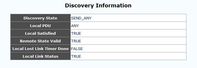
35 ah Configuration To use the OAM functions, the 802.3ah Function setting must be enabled. The 802.3ah mode is used to configure an OAM pair. In a pair, one unit must be active, while the other must be passive. We typically place the remote converter (CPE) in passive mode and make the local converter active. Passive is the default setting when 802.3ah function is enabled. In order to do Remote Loop Back test, this option must be enabled in both converters. By default it is enabled. The normal status when OAM is working is shown above. If OAM is not passing due to fiber disconnect, Discovery Status will be Fault. If OAM is not enabled, this status window will not even be shown. 35
 is set by the Send Packet Number. The default is 1 packet.")

36 3.7.2 Loop back Test The loop back test is a non-intrusive test which uses OAM packets and will not affect normal transmissions. The number of OAM frames used (the number of times the loop back is done) is set by the Send Packet Number. The default is 1 packet. The Packet Length (Not including CRC) controls the packet size of the OAM frames used for loop back testing. The default is 60 bytes. The CRC of Ethernet packets uses 4 bytes. Valid Ethernet packets range in size from 64 bytes to 1518 bytes. VLAN tag adds another 4 bytes for a maximum size of 1522 bytes. Any frame size larger than this is technically called a jumbo frame and is not IEEE802.3 compliant. The Loop Back Test Start is accomplished by clicking the Apply button ah is a slow protocol with a maximum throughput of 10 packets per second. The test above takes about 10 seconds for 100 packets. 36

37 ah Status 37
.")
38 The Global Config fields display the state of OAM, if OAM is enabled. We can also see the MAC addresses of the local and remote units in the OAM manageable pair. The Flags Field list the results of individual events based on the results of OAM protocol data units (OAMPDUs). Lastly, when two OAM devices start negotiation, there is Discovery Information passed between them. The results are shown here. Most information carried by OAMPDU is encoded using type-length-value (TLV) format. The first octet (or byte) of the OAMPDU indicates the type. This type is used to let the OAM client know how to decode the bytes containing the information. The next octet carries the length of the information. This display has TLV information for both the local and remote OAM units. 38
39 Ethernet OAM also defines a set of standard event conditions that Ethernet links should monitor in normal operation, and if detected, should be signaled to a peer entity. The Link Event Notification Status conditions reflect a degraded, but not yet inoperable, Ethernet connection. These conditions include threshold-crossing alarms on the frequency of symbol errors and frame errors. One of the most critical problems in an access network for carriers is differentiating between a simple power failure at the customer premise and an equipment or facility failure. Dying gasp provides this information by having a station indicate to the network that it is having a power failure. If remote management is lost, we simply need to check the Remote Dying Gasp Count register to see if it has been incremented. 39

40 3.8 Tools The Tools menu includes the System Reboot, Save and Restore settings and Firmware Upgrade functions System Reboot When the converter is rebooted, all counters and registers are cleared and the converter starts fresh. If OAM is enabled, the discovery process will start. After selecting the System Reboot menu item, a confirmation dialogue box will pop up. Click OK to reboot the converter or click Cancel to leave without rebooting. The converter requires about 20~25 seconds to fully reboot. 40
41 3.8.2 Save and Restore After performing configuration of the converter, the settings must be saved. Click the Save To Flash button to save settings. If you wish to abandon all settings and return to the previous settings before doing configuration, click the Load From Flash button. To restore all settings to factory default, click the Reset To Factory button. The IP address will also be reset, so you might lose management contact with the converter. So, be careful. 41
 user interface.")
42 3.8.3 Firmware Upgrade If functions are added or if factory default settings are changed, the firmware in the converter will require upgrading. The only method to do upgrade for this converter is through the local Web (HTTP) user interface. The firmware image is uploaded from the browser (Post), it is checked for integrity, the flash is erased and then the flash is written with the new image. DO NOT LET ANY POWER INTERRUPTION OCCUR DURING THE UPGRADE PROCEDURE. The Upload success! indicates the image was transferred OK. Do not do anything for the next 60 seconds!!!! After 60 seconds, you may click the link to re-login to the web interface. Login as usual. 42

43 3.9 Logout Logging out will ensure that the management session with the device is terminated. This is especially important if you are using a public computer to manage the device. Once logged out, a password must be entered to access the device again. Click the OK button to completely log out. Click the Cancel button to return to configuration of the device. 43
44 3.10 Troubleshooting Factory Default. Apply power to the device and allow seconds to fully boot. Using a pencil or ball-point pen, press the 'DEFAULT' recessed pushbutton switch (located on the face plate) and hold for 10 seconds or more then release. DO NOT POWER OFF; Allow the unit to again fully reboot (about 25 seconds). The factory default TCP/IP settings are: IP= netmask= GW= The username and password are both reset to 'admin'. Additionally, any VLAN, 1Q or bandwidth control will be disabled. All ports will be enabled, UTP ports set for auto-negotiation Reset The reset function is a hardware reboot. Using a pencil or ball-point pen, press the 'DEFAULT' recessed push-button switch (located on the face plate) and hold for 3 seconds (no more than 4 seconds) and release. The unit will reboot using the previous saved configuration. 44
45 LED Observations Power On At initial power on, PWR LED will not be lit. If active LAN is connected to the TP port, that Link and Speed LED will be lit. After 25 seconds the CPU has fully booted, PWR LED will be lit and any fiber link or alarm will be actively shown by the LEDs Error conditions: If all LEDs immediately light and never turn off, or if no LED ever lights, then the unit is possibly defective. Be sure to double check power source UTP Link Test Following a complete power and boot up (about 25 seconds) the converter will be active and LAN port will display LAN LNK state when connected to a live Ethernet circuit. The LAN SPD LED will be green when connected to Fast Ethernet (100M) and yellow when connected to Gigabit Ethernet (1000M). When connected to 10Base-T the LAN SPD LED will be off Fiber Link Test Following a complete power and boot up (about 25 seconds) the converter will be active. For IMC-1000MS-PH(E)12, place a known good SFP module into Fiber Port cage. Use a simplex patch cable (single fiber strand, LC to LC), route the SFP Tx back to the Rx optical connection. The FX LNK LED should light. For IMC-1000M-PH(E)12 & IMC-100M-PH(E)12, use a simplex patch cable (single fiber strand, SC to SC, ST to ST or FC to FC), route the Tx back to the Rx optical connection. The FX LNK LED should light. Caution: When performing a physical loop back on any fiber port, DO NOT connect the LAN port to a live Ethernet network. Doing so could create a broadcast storm. 45
12 or IMC-100M-PH(E)12 pair is operational. 3.10.4.")
46 Operation Checks Converter Check A very easy way to ensure a pair of IMC-1000M-PH(E)12 or IMC-100M-PH(E)12 is passing traffic, is to place them between two PCs. Connect PC1 to LAN of one converter and PC2 to LAN of the other converter. When the two PCs can ping each other, it indicates IMC- 1000M-PH(E)12 or IMC-100M-PH(E)12 pair is operational Ping Test With the device reset to factory default, connect a PC and configure the PC to the network ( recommended). Use a PC to ping the device at its factory default IP address of With a direct connection to PC, there should be no time outs and ping latency should be less than 1 millisecond. If you switch to another device, be sure to clear the PC ARP table. Every device has the same default IP address, but every unit has a different MAC address. To clear the PC s MAC table, open a command window and execute the command arp d. In addition, if you disconnect the PC from any LAN connection and then re-connect, the ARP table should also be cleared. 46
47 Web Access Test With the device reset to factory default, connect a PC and configure the PC to the network ( recommended). Use a PC to connect to the device at its factory default IP address of using a web browser (Internet Explorer, Firefox, Chrome, etc.). The local web page login page should display. Use admin/admin to login; the local main page should be displayed in the browser. If the ping test can pass and the login page can be displayed but login fails, we recommend that cookies be deleted. You may either delete all cookies for your browser or only the individual cookie created for the IP address of the device. 47
48 This page is intentionally left blank.

49
USER MANUAL FMC-1000M(S) Gigabit Ethernet OAM/IP Web Smart Media Converter
 Gigabit Ethernet OAM/IP Web Smart Media Converter") USER MANUAL FMC-1000M(S) Gigabit Ethernet OAM/IP Web Smart Media Converter CTC Union Technologies Co., Ltd. Far Eastern Vienna Technology Center (Neihu Technology Park) 8F, No. 60 Zhouzi St., Neihu, Taipei
USER MANUAL FMC-1000M(S) Gigabit Ethernet OAM/IP Web Smart Media Converter CTC Union Technologies Co., Ltd. Far Eastern Vienna Technology Center (Neihu Technology Park) 8F, No. 60 Zhouzi St., Neihu, Taipei
INSTRUCTION MANUAL FMX-GE-1000 ETHERNET TO OPTICAL MEDIA CONVERTER
 INSTRUCTION MANUAL FMX-GE-1000 ETHERNET TO OPTICAL MEDIA CONVERTER 191 FOREST AVENUE LOCUST VALLEY, NY 11560-2132 USA (800)-488-8378 / (516)-671-7278 FAX (516)-671-3362 sales@multidyne.com www.multidyne.com
IEXT224-4PH-L IEXT224-4PH-R Long Reach POE Extenders
 IEXT224-4PH-L IEXT224-4PH-R Long Reach POE Extenders 1 LEGAL The information in this publication has been carefully checked and is believed to be entirely accurate at the time of publication. CTC Union
USER MANUAL FRM MS Gigabit Ethernet OAM/IP Web Smart Media Converter
 USER MANUAL FRM220-1000MS Gigabit Ethernet OAM/IP Web Smart Media Converter CTC Union Technologies Co., Ltd. Far Eastern Vienna Technology Center (Neihu Technology Park) 8F, No. 60 Zhouzi St., Neihu,
PHB-200M PHB x 100/1000Base-T to 20x 100/1000Base-X
 SFP Patching Hub PHB-200M PHB-200 20x 100/1000Base-T to 20x 100/1000Base-X SFP Patching Hub PHB-200M is a 20-channel Managed SFP patching hub that converts copper 100/1000Base-TX to SFPs working at 100Mbps
GVM-1101 / GVM-1220 / GVM-1000 Web Smart Media Converter
 GVM-1101 / GVM-1220 / GVM-1000 Web Smart Media Converter User Manual Chapter 1 Overview 1.1 Overview GVM-1101 / GVM-1220 / GVM-1000 is remote Managed 10/100/1000 auto-negotiation Ethernet fiber media converter
ET100/NRZ. Ethernet WAN Bridge. 10/100Base-TX Ethernet over NRZ
 ET100/NRZ Ethernet WAN Bridge 10/100Base-TX Ethernet over NRZ CTC Union Technologies Co., Ltd. NeiHu Hi-Tech Park 8F, No. 60 Zhouzi Street. Neihu, Taipei, 114 Taiwan ET100/NRZ Ethernet WAN Bridge, User
PHB-200M PHB x 100/1000Base-T to 20x100/1000Base-X SFP Patching Hub
 SFP Patching Hub PHB-200M PHB-200 20x 100/1000Base-T to 20x100/1000Base-X SFP Patching Hub PHB-200M is a 20-channel Managed SFP patching hub that converts copper 100/1000Base-TX to SFPs working at 100Mbps
PHB-200M/PHB x 100/1000Base-T to 20x100/1000Base-X SFP Patching Hub
 SFP Patching Hub PHB-200M/PHB-200 20x 100/1000Base-T to 20x100/1000Base-X SFP Patching Hub PHB-200M is a 20-channel Managed SFP patching hub that converts copper 100/1000Base-TX to SFPs working at 100Mbps
PHB-200M PHB x 100/1000Base-T to 20x 100/1000Base-X FE/GbE Media Converter Concentrator
 Media Converter Concentrator PHB-200M PHB-200 20x 100/1000Base-T to 20x 100/1000Base-X FE/GbE Media Converter Concentrator PHB-200M is a 20-channel Managed Media Converter that converts copper 100/1000Base-TX
Industrial 5-Port Fast Ethernet Switches with SFP Slot and optional 4 PoE PSE Ports. Basic Model: KSD-541 PoE Model: KSD-541-P. Installation Guide
 Industrial 5-Port Fast Ethernet Switches with SFP Slot and optional 4 PoE PSE Ports Basic Model: KSD-541 PoE Model: KSD-541-P Installation Guide DOC.080104-1- (C) 2008 KTI Networks Inc. All rights reserved.
Hardened Web-Smart PoE & High Power PoE Ethernet Switch
 Quick Start Guide This quick start guide describes how to install and use the Hardened Web-Smart PoE (Power over Ethernet) and High Power PoE Ethernet Switch. This is the switch of choice for harsh environments
In-Band OAM Gigabit Ethernet to MM LC Fiber Media Converter - 550m, Metal Housing
 In-Band OAM Gigabit Ethernet to MM LC Fiber Media Converter - 550m, Metal Housing ET91000LCOAM *actual product may vary from photos DE: Bedienungsanleitung - de.startech.com FR: Guide de l'utilisateur
Industrial 5-Port Fast Ethernet Switches. with SFP Slot and optional 4 PoE PSE Ports. Basic Model: KSD-541. PoE Model: KSD-541-HP. Installation Guide
 Industrial 5-Port Fast Ethernet Switches with SFP Slot and optional 4 PoE PSE Ports Basic Model: KSD-541 PoE Model: KSD-541-HP Installation Guide DOC.141201-1- (C) 2014 KTI Networks Inc. All rights reserved.
S7055xM / S7075xM Web Smart Managed 5-Port / 7-Port 10/100 Fast Ethernet Switch w/vlan Support Installation Guide
 S7055xM / S7075xM Web Smart Managed 5-Port / 7-Port 10/100 Fast Ethernet Switch w/vlan Support Installation Guide January 2005 VERSITRON, Inc. 83 Albe Drive / Suite C Newark, DE 19702 A050130380 The information
STE100A Single Port IP to Serial Device Server
 STE100A Single Port IP to Serial Device Server CTC Union Technologies Co., Ltd. Far Eastern Vienna Technology Center (Neihu Technology Park) 8F, No. 60 Zhouzi St., Neihu, Taipei 114, Taiwan T +886-2-26591021
KSD-800 Series. Installation Guide. Industrial 8-Port Fast Ethernet Switches with Fiber Connectivity DOC A -1-
 KSD-800 Series Industrial 8-Port Fast Ethernet Switches with Fiber Connectivity Installation Guide DOC.110516A -1- (C) 2005 KTI Networks Inc. All rights reserved. No part of this documentation may be reproduced
Hardened Web-Smart High Power PoE Ethernet Switch
 Quick Start Guide This quick start guide describes how to install and use the Hardened Web-Smart High Power PoE (Power over Ethernet) Ethernet Switch. This is the switch of choice for harsh environments
Save installation time and money with PoE
 8-Port Gigabit Ethernet PoE+ Web-Managed Switch with 2 SFP Ports IEEE 802.3at/af Power over Ethernet (PoE+/PoE) Compliant, 140 W, Endspan, Desktop, 19" Rackmount Part No.: 561167 Save installation time
Quick Start Guide. Physical Description. The Port Status LEDs
 Quick Start Guide This quick start guide describes how to install and use the Hardened PoE Ethernet Switch. Capable of operating at temperature extremes of -40 C to +75 C, this is the switch of choice
LevelOne GES GE with 1 Combo SFP Web Smart Switch User Manual
 LevelOne GES-0852 8 GE with 1 Combo SFP Web Smart Switch User Manual Version 1.0-1109 1 FCC Certifications This Equipment has been tested and found to comply with the limits for a Class A digital device,
CTC Union Technologies Co., Ltd. Far Eastern Vienna Technology Center (Neihu Technology Park) 8F, No. 60, Zhouzi St., Neihu, Taipei 114, Taiwan
 8F, No. 60, Zhouzi St., Neihu, Taipei 114, Taiwan") CTC Union Technologies Co., Ltd. Far Eastern Vienna Technology Center (Neihu Technology Park) 8F, No. 60, Zhouzi St., Neihu, Taipei 114, Taiwan T +886-2-26591021 F +886-2-26590237 E sales@ctcu.com techsupport@ctcu.com
CTC Union Technologies Co., Ltd. Far Eastern Vienna Technology Center (Neihu Technology Park) 8F, No. 60, Zhouzi St., Neihu, Taipei 114, Taiwan T +886-2-26591021 F +886-2-26590237 E sales@ctcu.com techsupport@ctcu.com
24 port gigabit copper PoE + 4x SFP smart-managed
 ALLNET ALL-SG8428PM 24 port gigabit copper PoE + 4x SFP smart-managed 24 Port gigabit non-blocking switch architecture supports NWay protocol (10/100/1000Mbps) and duplex mode (half/full) auto detection
Ethernet Media Converter Web Smart Series. User Manual
 Ethernet Media Converter Web Smart Series User Manual v1.0 May. 2011 i Ethernet Media Converter Web Smart Series FVS-3800, 10/100BASE-TX to 100BASE-X SFP Converter FVS-3200, 10/100BASE-TX to 100BASE-FX
100Base-FX to 10/100Base-TX. PoE. Media Converter. FCU-1802Px. User s Manual
 100Base-FX to 10/100Base-TX PoE Media Converter FCU-1802Px User s Manual Trademarks Copyright Antaira Technologies 2013. Contents subject to revision without prior notice. Antaira is a registered trademark
Designed for Railway application and fully compliant with the requirement of EN50155/EN standard
 IGS-9084GP Industrial 12-port managed Gigabit Ethernet switch with 8x10/100/1000Base-T(X) and 4x100/1000Base-X, SFP socket Features Designed for Railway application and fully compliant with the requirement
FCN-3112 Series. 10/100/1000TX to 1000SX SNMP Managed Media Converter. Version 1.0 User Manual
 FCN-3112 Series 10/100/1000TX to 1000SX SNMP Managed Media Converter Version 1.0 User Manual Copyright 2018 Antaira Technologies, LLC. All Rights Reserved This document contains information, which is protected
Preface. Managed Media Converter Chassis System
 Preface The Managed Media Converter Chassis System supports the Media Converter Chassis to monitor the each Media Converter ( CO ) or Chassis Manager status and to configure advanced function of the Managed
VDTU2-B110 VDSL2 LAN Extender
 VDTU2-B110 VDSL2 LAN Extender 1 Copyright by CTC UNION Communications Inc., all right reserved The information in this document has been checked carefully and is believed to be correct as of the date of
Installation Guide. Web Smart Managed 10/100 Fast Ethernet Switches with VLAN Support
 Installation Guide Web Smart Managed 10/100 Fast Ethernet Switches with VLAN Support KS-115FM-V KS-117FM-V DOC.060510-1- (C) 2006 KTI Networks Inc. All rights reserved. No part of this documentation may
A valid network connection established. Transmitting or receiving data. ACT stands for ACTIVITY.
 Quick Start Guide This quick start guide describes how to install and use the Hardened Web-Smart PoE (Power over Ethernet) Ethernet Switch. Port and LED number will vary on different models. This user's
User s Manual IGT-902 / 902T IGT-902S / 902TS IGT-905A. 10/100/1000Base-T to 1000Base-SX / LX. Industrial Managed Media Converter
 User s Manual IGT-902 / 902T IGT-902S / 902TS IGT-905A 10/100/1000Base-T to 1000Base-SX / LX Industrial Managed Media Converter -1- Trademarks Copyright PLANET Technology Corp. 2010. Contents subject to
RGS-7244GP / RGS-7244GP-E
 Rack-Mount Managed Gigabit 28-port rack-mount managed Gigabit Ethernet switch with 24x10/100/1000Base-T(X) and 4x1000Base-X, SFP socket Wireless Full Gigabit O-Ring ORing s switches are intelligent switches.
Smart Managed PoE-Powered 5-Port Gigabit Switch
 Product Highlights Powered by Receives power from upstream Switch or Injector No local power source needed Ideal for use in hard to reach locations Extender Supports Pass-through Propagates power to one
User's Manual FT-902 FT-902S15 FT-902S35 FT-902S50 FT-905A FT-906A20 / FT-906B20. 10/100Base-TX to 100Base-FX. Managed Media Converter
 User's Manual FT-902 FT-902S15 FT-902S35 FT-902S50 FT-905A FT-906A20 / FT-906B20 10/100Base-TX to 100Base-FX Managed Media Converter Trademarks Copyright PLANET Technology Corp. 2010. Contents subject
Save installation time and money with PoE.
 48-Port Gigabit Ethernet PoE+ Layer2+ Managed Switch with 10 GbE Uplink 48 x PoE ports, IEEE 802.3at Power over Ethernet (PoE+), Layer 2+, 2 x 10 GbE SFP+ open slots, Endspan, 19" Rackmount Part No.: 561112
Save installation time and money with PoE
 16-Port Gigabit Ethernet PoE+ Web-Managed Switch with 2 SFP Ports IEEE 802.3at/af Power over Ethernet (PoE+/PoE) Compliant, 220 W, Endspan, 19" Rackmount Part No.: 561341 Save installation time and money
RGS-7244GP / RGS-7244GP-E
 RGS-7244GP / RGS-7244GP-E Industrial 28-port rack mount managed Gigabit Ethernet switch with 24x10/100/1000Base-T(X) and 4x1000Base-X, SFP socket Features Support 24x10/100/1000Base-T(X) and 4x1000Base-X
FRM220A-1000EAS/X 4-Port OAM/IP Gigabit Ethernet Media Converter/Switch
 FRM220A-1000EAS/X 4-Port OAM/IP Gigabit Ethernet Media Converter/Switch CTC Union Technologies Co., Ltd. Far Eastern Vienna Technology Center (Neihu Technology Park) 8F, No. 60 Zhouzi St., Neihu, Taipei
Media Converters & Chassis
 Expandable Chassis System The Chassis-based Media Converter product lineup includes various independent media converters and a chassis capable of housing up to 16 media converters. You can start with a
RGS-7168GCP / RGS-7168GCP-E
 RGS-7168GCP / RGS-7168GCP-E Features Industrial 24-port rack-mount managed Gigabit Ethernet switch with 16xGigabit combo ports and 8x100/1000Base-X, SFP socket Support 24 Gigabit ports with 16 x Gigabit
Rugged Industrial Media Converter
 MLB-F4002-SM Rugged Industrial Media Converter USER MANUAL MLB-F4002-SM True Mini Industrial Media Converter FCC MARKING This Equipment has been tested and found to comply with the limits for a Class A
MF727xS INDUSTRIAL 10/100BASE-TX TO 100BASE-FX MEDIA CONVERTER. Installation Guide
 1 INDUSTRIAL 10/100BASE-TX TO 100BASE-FX MEDIA CONVERTER Installation Guide October 2008 VERSITRON, Inc. 83C Albe Drive Newark, DE 19702 800-537-2296 2 PROPRIETARY DATA All data in this manual is proprietary
1Industrial Ethernet Switch
 Ethernet Switch Rack-Mount Managed Gigabit Ethernet Switch RGS-7244GP / RGS-7244GP-E 28-port rack-mount managed Gigabit Ethernet switch with 24x10/100/1000Base-T(X) and 4x1000Base-X, SFP socket Features
DES P MANUAL WEBSMART SWITCH V1.05
 DES-1100-10P MANUAL WEBSMART SWITCH V1.05 Table of Content Getting Started...3 WEB Configuration...4 Home...4 System...5 Power Over Ethernet...6 LED Power Saving...8 Fundamentals...9 Security...21 Statistics...22
DW- SW-PoE-24M. wwww.denwaip.com
 DW- SW-PoE-24M w DW- SW-PoE-24M OVERVIEW The 24 -Port managed PoE Switch, with 24 100Mbit RJ45 ports,2 Gigabit SFP port and 2 Gigabit Uplink, model DW-SW-PoE-24M, reduces equipment and installation costs
M727xSP. PoE Powered. Ethernet Media Converter 10/100BASE-TX TO 100BASE-SX/LX. Installation Guide
 M727xSP PoE Powered Ethernet Media Converter 10/100BASE-TX TO 100BASE-SX/LX Installation Guide September 2009 VERSITRON, Inc. 83 Albe Drive - Suite C Newark, DE 19702 www.versitron.com www.versitron.com
L Port 10/100/1000T PoE + 2-Port Gigabit SFP + Managed Switch
 L2 + 24-Port 10/100/1000T PoE + 2-Port Gigabit SFP + Managed Switch PS-B8266VF series are high performance and cost efficiency 802.3af/at PoE Smart Switch. It comes with 24 dedicated 10/100/1000Mbps PSE
1Industrial Ethernet Switch
 Ethernet Switch DIN-Rail Managed Fast PoE Ethernet Switch v2.0a / Feb, 2013 Features 10-port managed PoE Ethernet switch with 8x10/100Base- T(X) P.S.E. and 2xGigabit combo ports, SFP socket, 24V power
Save installation time and money with PoE.
 16-Port Gigabit Ethernet PoE+ Web-Managed Switch with 2 SFP Ports 16 x PoE ports, IEEE 802.3at/af Power over Ethernet (PoE+/PoE), 2 x SFP, Endspan, Desktop, 19" Rackmount Part No.: 560931 Save installation
HES-3109 SERIES 9 PORTS 10/100/1000BASE-T MANAGEMENT ETHERNET SWITCH
 HES-3109 SERIES 9 PORTS 10/100/1000BASE-T MANAGEMENT ETHERNET SWITCH 8 PORTS 10/100/1000BASE-T MANAGEMENT ETHERNET SWITCH WITH 1 PORT 1000BASE-X UPLINK OR 1 PORT 100/1000BASE-X UPLINK 8 PORTS 10/100/1000BASE-T
IMC-P111FX Series IMC-P111P Series
 DIN-Rail Ethernet to Fiber Media Converter v.1 / Oct, 017 IMC-P111FX Series IMC-P111P Series IMC-P111FX Series IMC-P111P Series Features Designed for Railway application and fully compliant with the requirement
IMC-21GA Quick Installation Guide
 IMC-21GA Quick Installation Guide Moxa Industrial Media Converter Edition 4.0, June 2017 Technical Support Contact Information www.moxa.com/support Moxa Americas: Toll-free: 1-888-669-2872 Tel: 1-714-528-6777
Quick Start Guide Elinx ESW500 Series. Managed Din Rail Ethernet Switch
 Quick Start Guide Elinx ESW500 Series Managed Din Rail Ethernet Switch ESW500 Series Documentation Number: ESW500series-1012qsg International Headquarters: 707 Dayton Road Ottawa, IL 61350 USA Phone (815)
IMC-P111FX / IMC-P111P Series
 DIN-Rail Ethernet to Fiber Media Converter v1.0 / Jan, 013 IMC-P111FX / IMC-P111P Series Features IEC 61850-3 Ethernet to fiber media converter with 1x10/100Base-T(X) to 1x100Base-FX fiber or 1x100Base-FX
Industrial Gigabit Managed Switches
 Product Highlights Rugged, Hardened Design Design to operate in wide temperature ranges, vibration, shock, allowing the switches to be deployed in enclosures or cabinets in outdoor locations High Availability
Save installation time and money with PoE.
 8-Port Gigabit Ethernet PoE+ Web-Managed Switch with 2 SFP Ports 8 x PoE ports, IEEE 802.3at/af Power-over-Ethernet (PoE+/PoE), 2 x SFP, Endspan, Desktop, 19" Rackmount Part No.: 561051 Save installation
PoE Powered 10/100BASE-TX to 100BASE-FX Media Converters. KC-351 Series. Installation Guide
 PoE Powered 10/100BASE-TX to 100BASE-FX Media Converters KC-351 Series Installation Guide -1- DOC.070820-KC-351 (C) 2007 KTI Networks Inc. All rights reserved. No part of this documentation may be reproduced
Product Overview. Switch Models CHAPTER
 CHAPTER 1 The Cisco CGS 2520 switches, also referred to as the switch, are Ethernet switches that you can connect devices such as Intelligent Electronic Devices (IEDs), distributed controllers, substation
Hardened Managed 10-port 10/100BASE (8 x PoE) and 2-port Gigabit Ethernet Switch SFP
 and 2-port Gigabit Ethernet Switch SFP") Hardened Managed 10-port 10/100BASE (8 x PoE) and 2-port Gigabit Ethernet Switch UL508 SFP Option 15W PoE 30W PoE Overview EtherWAN's provides a hardened 12-port switching platform supporting IEEE802.3at
Hardened Managed 10-port 10/100BASE (8 x PoE) and 2-port Gigabit Ethernet Switch UL508 SFP Option 15W PoE 30W PoE Overview EtherWAN's provides a hardened 12-port switching platform supporting IEEE802.3at
Industrial 8-port managed Gigabit PoE Ethernet switch with 8x10/100/1000Base-T(X) P.S.E.
 P.S.E.") IGPS-9080 Series Features Industrial 8-port managed Gigabit PoE Ethernet switch with 8x10/100/1000Base-T(X) P.S.E. Supports O-Ring (recovery time < 30ms over 250 units of connection) and MSTP(RSTP/STP
IGPS-9080 Series Features Industrial 8-port managed Gigabit PoE Ethernet switch with 8x10/100/1000Base-T(X) P.S.E. Supports O-Ring (recovery time < 30ms over 250 units of connection) and MSTP(RSTP/STP
Industrial 6-port unmanaged Gigabit PoE Ethernet switch with 4x10/100/1000Base-T(X) P.S.E. and
 P.S.E. and") Industrial 6-port unmanaged Gigabit PoE Ethernet switch with 4x10/100/1000Base-T(X) P.S.E. and 2x100/1000Base-X, SFP socket, 24VDC power input Features provide 4x10/100/1000Base-T(X) PoE (P.S.E.) ports
Industrial 6-port unmanaged Gigabit PoE Ethernet switch with 4x10/100/1000Base-T(X) P.S.E. and 2x100/1000Base-X, SFP socket, 24VDC power input Features provide 4x10/100/1000Base-T(X) PoE (P.S.E.) ports
Gigabit EasySmart Switches
 Product Highlights Gigabit Ethernet Speeds High-speed ports provide the latest Ethernet technology while retaining backward compatibility for connections to older computers and equipment Layer 2 VLAN Control
10/100/1000T to Mini-GBIC Industrial Switch Converter 10/100/1000T to 1000SX/LX Industrial Switch Converter. AMG9011G-H (-40 to 75C) User Manual
 User Manual") 10/100/1000T to Mini-GBIC Industrial Switch Converter 10/100/1000T to 1000SX/LX Industrial Switch Converter AMG9011G-H (-40 to 75C) User Manual www.amgsystems.com Content Overview...1 Introduction... 1
10/100/1000T to Mini-GBIC Industrial Switch Converter 10/100/1000T to 1000SX/LX Industrial Switch Converter AMG9011G-H (-40 to 75C) User Manual www.amgsystems.com Content Overview...1 Introduction... 1
INDUSTRIAL POE SWITCH
 STEP X - Name of Step QUICK START GUIDE LIE1014A, LIE1080A, LIE1082A INDUSTRIAL POE SWITCH 24/7 TECHNICAL SUPPORT AT 877.877.2269 OR VISIT BLACKBOX.COM STEP 1 - Hardware Description LIE1014A LIE1080A TABLE
RuggedNet. RuggedNet GPoE+/Mi KEY FEATURES. Managed Industrial 10/100/1000 Power Source Equipment (PSE) PoE/PoE+ Ethernet Fiber Switch
 PoE/PoE+ Ethernet Fiber Switch") RuggedNet TM Managed Industrial 10/100/1000 Source Equipment (PSE) PoE/PoE+ Ethernet Fiber Switch The is an industrial ruggedized and temperature-hardened Ethernet switch that features one or two 1000BASE-X
RuggedNet TM Managed Industrial 10/100/1000 Source Equipment (PSE) PoE/PoE+ Ethernet Fiber Switch The is an industrial ruggedized and temperature-hardened Ethernet switch that features one or two 1000BASE-X
8~14-Port Managed Ethernet Switch
 8~14-Port Managed Ethernet Switch Quick Installation Guide Overview The Managed Ethernet Switch solutions are designed for supporting standard industrial applications. Managed switches are easier to prioritize,
Gigabit Network Switches
 Network Transmission Gigabit Network Switches Layer 2 (Non-PoE) Layer 3 (PoE-at) OVERVIEW This Enterprise-Class Network Switch provides 24 Gigabit Ethernet ports with 4 shared 100/1000Mbps SFP slots. This
INDUSTRIAL 1000BASE-T TO 1000BASE-X MEDIA CONVERTERS. KCD-400 Series. Installation Guide
 INDUSTRIAL 1000BASE-T TO 1000BASE-X MEDIA CONVERTERS KCD-400 Series Installation Guide DOC.060227-KCD-400-1- (C) 2005 KTI Networks Inc. All rights reserved. No part of this documentation may be reproduced
Product names mentioned in this manual may be trademarks or registered trademarks of those products.
 FCC Statement The FCC (Federal Communications Commission) restricts the amount of radio frequency emission and radiation coming from computer equipment. The equipment introduced in this manual has been
Industrial 3-Port Fast Ethernet Media Converter Switches
 Industrial 3-Port Fast Ethernet Media Converter Switches KSD-103-A series KSD-103-B series Installation Guide DOC.081111 1/20 (C) 2008 KTI Networks Inc. All rights reserved. No part of this documentation
Industrial Gigabit Managed Ethernet Switch
 HMG-828 HMG-828E Industrial Gigabit Managed Ethernet Switch Features High Performance Network Switching Technology Complies with IEEE 802.3, IEEE 802.3u, IEEE 802.3X, IEEE 802.1p, IEEE 802.1q, IEEE 802.1d,
FWRIII-2105 SERIES. 4 ports 10/100Mbps RJ-45; built-in IEEE802.11n WiFi and 1 port 100Mbps SFP slot uplink Residential Gateway. Residential Gateway
 FWRIII-2105 SERIES 4 ports 10/100Mbps RJ-45; built-in IEEE802.11n WiFi and 1 port 100Mbps SFP slot uplink Residential Gateway 4 ports 10/100Mbps RJ-45; built-in IEEE802.11n WiFi and 1 port 100Mbps SFP
Layer 2 Gigabit Industrial Managed Switches
 DGS -F3000 Series Layer 2 Gigabit Industrial Managed Switches Features Robust Design IP30-rated metal housing Fanless, passive cooling design High EMC endurance Network Redundancy Ethernet Ring Protection
SWP-0208G, 8+2SFP. 8-Port Gigabit Web Smart Switch. User s Manual
 SWP-0208G 1 SWP-0208G, 8+2SFP 8-Port Gigabit Web Smart Switch User s Manual Version: 3.4 April 1, 2008 2 TABLE OF CONTENT 1.0 INTRODUCTION...4 1.1 MAIN FEATURES...4 1.2 START TO MANAGE THIS SWITCH...6
Hardened PoE Ethernet Switch
 Quick Start Guide This quick start guide describes how to install and use the Hardened PoE Ethernet Switch. This is the switch of choice for harsh environments constrained by space. Physical Description
Entry Line Industrial Gigabit Ethernet Bridging Converter, PoE+ optional 1x 10/100/1000Base-T, 1x 100/1000 SFP
 Entry Line Industrial Gigabit Ethernet Bridging Converter, PoE+ optional 1x 10/100/1000Base-T, 1x 100/1000 SFP General The IP protocol has already left the in-house environment and is going to take all
Modular 8-Port Mid-span Power over Ethernet Injector
 Modular 8-Port Mid-span Power over Ethernet Injector KPOE-800-1P KPOE-800-2P Installation Guide DOC.090201 1 (C) 2008 KTI Networks Inc. All rights reserved. No part of this documentation may be reproduced
HES-3106-PLUS SERIES
 HES-3106-PLUS SERIES 5 PORTS 10/100/1000BASE-T ETHERNET MANAGED SWITCH WITH 1 PORT 1000BASE-X or 100/1000BASE-X UPLINK User s Guide Version 0.92 Trademarks CTS is a registered trademark of Connection Technology
SF7085xM. 8-Port 10/100 Industrial Managed Switch. Operation Manual. Rev. B
 1 8-Port 10/100 Industrial Managed Switch Operation Manual Rev. B May 2009 VERSITRON, Inc. 83 Albe Drive / Suite C Newark, DE 19702 The information contained in this document is subject to change without
SML40-CH04 Chassis CWDM Passive 4 Slot Rack
 SML40-CH04 Chassis CWDM Passive 4 Slot Rack The information in this publication has been carefully checked and is believed to be entirely accurate at the time of publication. CTC Union Technologies assumes
Device Server for the conversion of serial interfaces (RS-232/422/485) to IP.
 to IP.") Manual Entry Line Industrial Gigabit Ethernet Switch 4x 10/100/1000Base-T, 1x SFP Ports MICROSENS General The IP protocol has already left the in-house environment and is going to take all remaining communication
Manual Entry Line Industrial Gigabit Ethernet Switch 4x 10/100/1000Base-T, 1x SFP Ports MICROSENS General The IP protocol has already left the in-house environment and is going to take all remaining communication
General. 5 and 8 port Fast Ethernet switches. 6 and 8 Port Gigabit Ethernet switches. Switches with fiber uplink
 Entry Line Industrial Gigabit Ethernet Switch 4x 10/100/1000Base-T with PoE+, 1x 10/100/1000Base-T or 100/1000Base-X Combo Port, 1x 100/1000Base X SFP Slot General The IP protocol has already left the
EP Port Managed Gigabit Switch with 4 x IEEE 802.3at + 20 x IEEE 802.3af PoE
 EP220-28-193 28-Port Managed Gigabit Switch with 4 x IEEE 802.3at + 20 x IEEE 802.3af PoE Overview To fulfill the needs of higher power requirement of PoE network applications with Gigabit speed transmission,
Designed, built, and tested for troublefree operation in extreme conditions
 SEL-2730M Managed 24-Port Ethernet Switch Designed, built, and tested for troublefree operation in extreme conditions Highest mean time between failures (MTBF) in the industry provides years of reliable
Save installation time and money with PoE. Power over Ethernet 802.3at
 24-Port Gigabit Ethernet PoE+ Web-Managed Switch with 2 SFP Ports 24 x PoE ports, IEEE 802.3at/af Power over Ethernet (PoE+/PoE), 2 x SFP, Endspan, 19" Rackmount Part No.: 560559 Save installation time
Copyright PLANET Technology Corp Contents subject to revision without prior notice.
 Copyright Copyright PLANET Technology Corp. 2004. Contents subject to revision without prior notice. PLANET is a registered trademark of PLANET Technology Corp. The information in this manual is subject
KGS-510F Web Smart 6-Port Gigabit Ethernet Switch with Fiber Connectivity Installation Guide
 KGS-510F Web Smart 6-Port Gigabit Ethernet Switch with Fiber Connectivity Installation Guide DOC.060118-1- (C) 2005 KTI Networks Inc. All rights reserved. No part of this documentation may be reproduced
Best Connectivity. 5-Port 10/100Mbps Desktop Switch with 4-Port PoE
 NS0098 is a 5 10/100Mbps ports unmanaged switch that requires no configuration and provides 4 PoE (Power over Ethernet) ports. It can automatically detect and supply power with all IEEE 802.3af compliant
User Manual Entry Line Industrial Gigabit Ethernet High Power 60/95 W PoE Injector
 User Manual Entry Line Industrial Gigabit Ethernet High Power 60/95 W PoE Injector Gigabit Ethernet Switch with PoE+ for Industrial Use Page 2/11 Table of Contents General... 3 Benefits... 3 Front View...
1Industrial Ethernet Switch
 Ethernet Switch DIN-Rail Managed Gigabit PoE Ethernet Switch Features 12-port managed Gigabit PoE Ethernet switch with 8x10/100/1000Base-T(X) P.S.E. ports and 4x100/1000Base-X, SFP socket 1 Ethernet Switch
MF BASE-T to 1000BASE-X INDUSTRIAL MEDIA CONVERTER WITH SFP SUPPORT INSTALLATION GUIDE
 1000BASE-T to 1000BASE-X INDUSTRIAL MEDIA CONVERTER WITH SFP SUPPORT INSTALLATION GUIDE September 2006 VERSITRON, Inc. 83 Albe Drive - Suite C Newark, DE 19702 2 PROPRIETARY DATA All data in this manual
1Industrial Ethernet Switch
 Ethernet Switch Rack-Mount Managed Ethernet Switch v1.0a / Jun, 2016 1 Ethernet Switch Features 26-port rack mount managed Ethernet switch with 24x10/100Base-T(X) and 2xgigabit combo, SFP socket Support
Industrial RS-232/ RS-422/ RS-485 over Ethernet Media Converter
 / S15 / Industrial RS-232/ RS-422/ RS-485 over Ethernet Media Converter Serial Interface One RS-232 port and one RS-422/485 port to one Base-FX Media Conversion Cost effective solutions of RS-232/ RS-422/
CVT-2512 SERIES CVT-3512 SERIES
 CVT-2512 SERIES 10/100BASE-TX to 100BASE-FX Standalone Managed Media Converter with 802.3ah OAM compliance CVT-3512 SERIES 10/100/1000BASE-T to 1000BASE-X Standalone Managed Media Converter with 802.3ah
10/100/1000Mbps. Gigabit Ethernet Switch GSW-2401/GSW User's Manual
 10/100/1000Mbps Gigabit Ethernet Switch GSW-2401/GSW-1601 User's Manual Trademarks Copyright PLANET Technology Corp. 2005. Content subjects to revision without prior notice. PLANET is a registered trademark
PoE Powered Gigabit Ethernet Media Converters 1000BASE-T TO 1000BASE-SX/LX. KGC-352 Series. Installation Guide
 PoE Powered Gigabit Ethernet Media Converters 1000BASE-T TO 1000BASE-SX/LX KGC-352 Series Installation Guide DOC.070820-KGC-352-1- (C) 2007 KTI Networks Inc. All rights reserved. No part of this documentation
MC100FX-TX-PoE Media Converter User Manual
 GE Security MC100FX-TX-PoE Media Converter User Manual P/N 1069178 REV 1.0 ISS 22FEB10 Copyright Disclaimer Trademarks and patents Intended use FCC compliance 2010 GE Security, Inc. This document may not
ICPDAS FSM-510G Series Ethernet Management Switch Quick Start
 ICPDAS FSM-510G Series Ethernet Management Switch Quick Start Version 1.0, Dec 2014 Overview The Management Ethernet Switch solutions are designed for supporting standard industrial applications. Managed
KSD-800M Industrial Managed 8-Port Fast Ethernet Switches with Fiber Connectivity Operation Manual
 KSD-800M Industrial Managed 8-Port Fast Ethernet Switches with Fiber Connectivity Operation Manual for software v1.092 and later DOC.080604-1- (C) 2005 KTI Networks Inc. All rights reserved. No part of