802.11n WLAN Portable Repeater
|
|
|
- Aubrey Bryant
- 6 years ago
- Views:
Transcription


1 802.11n WLAN Portable Repeater User s Manual 1
2 Table of Contents 1 Introduction... 5 Features... 5 Device Requirements... 5 Using this Document... 6 Notational conventions... 6 Typographical conventions... 6 Special messages... 6 Getting Support Getting to know the device... 7 Computer / System requirements... 7 Package Contents... 7 LED meanings & activations... 7 Top Side... 7 Rear and Left Panel and bottom Side Computer configurations under different OS, to obtain IP address automatically... 9 For Windows 98SE / ME / 2000 / XP... 9 For Windows Vista-32/ For Windows 7-32/ For Windows 8-32/ Connecting your device Connecting the Hardware WPS Pairing between 11n Repeater and Wireless xdsl/cable Modem Advanced Configuration Advanced Configuration Repeater Mode (Extend your Wireless Network) AP Mode (Extend your Wired Network to allow wireless devices to connect your wired network using Wi-Fi) Wireless Connection What the Internet/WAN access of your own Network now is Internet/WAN access is the DHCP client Internet/WAN access is the Static IP Internet/WAN access is the PPPoE client
3 7 Getting Started with the Web pages Accessing the Web pages Testing your Setup Default device settings Quick Setup LAN Interface LAN Interface Setup Changing the LAN IP address and subnet mask DHCP Static IP Configuration Wireless Network Wireless Basics WPS Setup (For AP mode only) Wireless Advanced Settings Wireless Access Control Mode Allow Listed Reboot/Reset Reboot/Reset Firmware Upgrade About firmware versions Manually updating firmware Backup/Restore Settings Save Settings to File Load Settings from File Password Setting your username and password Status Active Client Table Statistics A Configuring your Computers Configuring Ethernet PCs Before you begin Windows XP PCs Windows 2000 PCs Windows Me PCs Windows 95, 98 PCs Windows NT 4.0 workstations Assigning static Internet information to your PCs
4 B C IP Addresses, Network Masks, and Subnets IP Addresses Structure of an IP address Network classes Subnet masks UPnP Control Point Software on Windows ME/XP UPnP Control Point Software on Windows ME UPnP Control Point Software on Windows XP with Firewall SSDP requirements D Troubleshooting Troubleshooting Suggestions Diagnosing Problem using IP Utilities ping nslookup E Glossary
5 1 Introduction Congratulations on becoming the owner of the Wireless Gateway. You will now be able to access the Internet using your high-speed xdsl/cable modem connection. This User Guide will show you how to connect your Wireless Gateway, and how to customize its configuration to get the most out of your new product. Features The list below contains the main features of the device and may be useful to users with knowledge of networking protocols. If you are not an experienced user, the chapters throughout this guide will provide you with enough information to get the most out of your device. Features include: 10/100Base-T Ethernet router to provide Internet connectivity to all computers on your LAN Network address translation (NAT) functions to provide security for your LAN Network configuration through DHCP Server and DHCP Client Services including IP route and DNS configuration, RIP, and IP Supports remote software upgrades User-friendly configuration program accessed via a web browser The Wireless Gateway has the internal Ethernet switch allows for a direct connection to a 10/100BASE-T Ethernet network via an RJ-45 interface, with LAN connectivity for both the Wireless Gateway and a co-located PC or other Ethernet-based device. Device Requirements In order to use the Wireless Gateway, you must have the following: One RJ-45 Broadband Internet connection via cable modem or xdsl modem Instructions from your ISP on what type of Internet access you will be using, and the addresses needed to set up access One or more computers each containing an Ethernet card (10Base-T/100Base-T network interface card (NIC)) TCP/IP protocol for each PC For system configuration using the supplied a. web-based program: a web browser such as Internet Explorer v4 or later, or Netscape v4 or later. Note that version 4 of each browser is the minimum version 5
6 requirement for optimum display quality, use Internet Explorer v5, or Netscape v6.1 Note You do not need to use a hub or switch in order to connect more than one Ethernet PC to your device. Instead, you can connect up to four Ethernet PCs directly to your device using the ports labeled Ethernet on the rear panel. Using this Document Notational conventions Acronyms are defined the first time they appear in the text and also in the glossary. For brevity, the Wireless Gateway is referred to as the device. The term LAN refers to a group of Ethernet-connected computers at one site. Typographical conventions Italic text is used for items you select from menus and dropdown lists and the names of displayed web pages. Bold text is used for text strings that you type when prompted by the program, and to emphasize important points. Special messages This document uses the following icons to draw your attention to specific instructions or explanations. Note Provides clarifying or non-essential information on the current topic. Definition Explains terms or acronyms that may be unfamiliar to many readers. These terms are also included in the Glossary. WARNING Provides messages of high importance, including messages relating to personal safety or system integrity. Getting Support Supplied by: Helpdesk Number: Website: 6
7 2 Getting to know the device Computer / System requirements 1. Pentium 200MHZ processor or above 2. Windows 98SE, Windows Me, Windows 2000, Windows XP, Windows Vista, Windows 7 and Windows 8 Package Contents 1. 11n Repeater 2. Quick Installation Guide 3. Ethernet Cable (RJ-45) LED meanings & activations Top Side The Top Side contains lights called Light Emitting Diodes (LEDs) that indicate the status of the unit. Figure 1: Top Side and LEDs 7

8 Label Color Function Wifi Signal blue On Wireless Signal Strength Off: No WLAN link Wireless blue On: WLAN link established and active Blink: Valid Wireless packet being transferred WPS blue Off: WPS link isn t established and active Blink: Valid WPS packet being transferred Ethernet blue On: LAN link established and active Off: No LAN link Blink: Valid Ethernet packet being transferred Rear and Left Panel and bottom Side The rear and right panel and bottom side contains a Restore Defaults button, the ports for the unit's data and power connections. Label Ethernet WPS / RESET Function Connects the device via LAN Ethernet to a PC WPS Press this button for 3 full seconds and the WPS LED will flash to start WPS. Now go to the wireless adapter or device and press its WPS button. Make sure to press the button within 120 seconds (2 minutes) after pressing the router's WPS button. RESET Reset button. RESET the 11n Repeater to its default settings. Press this button for at least 3 full seconds to RESET device to its default settings. 8
.")
9 3 Computer configurations under different OS, to obtain IP address automatically Before starting the 11n Repeater configuration, please kindly configure the PC computer as below, to have automatic IP address / DNS Server. For Windows 98SE / ME / 2000 / XP 1. Click on "Start" -> "Control Panel" (in Classic View). In the Control Panel, double click on "Network Connections" to continue. 9

10 2. Single RIGHT click on "Local Area connection", then click "Properties". 10

11 3. Double click on "Internet Protocol (TCP/IP)". 11

12 4. Check "Obtain an IP address automatically" and "Obtain DNS server address automatically" then click on "OK" to continue. 5. Click "Show icon in notification area when connected" (see screen image in 3. above) then Click on "OK" to complete the setup procedures. 12

13 For Windows Vista-32/64 1. Click on Start -> Control Panel -> View network status and tasks. 13

14 2. In the Manage network connections, click on Manage network connections to continue. 14

15 3. Single RIGHT click on "Local Area connection", then click "Properties". 15

16 4. The screen will display the information "User Account Control" and click "Continue" to continue. 5. Double click on "Internet Protocol Version 4 (TCP/IPv4)". 16

17 6. Check "Obtain an IP address automatically" and "Obtain DNS server address automatically" then click on "OK" to continue. 17
 ->")
18 For Windows 7-32/64 7. Click on Start -> Control Panel (in Category View) -> View network status and tasks. 18

19 8. In the Control Panel Home, click on Change adapter settings to continue. 19

20 9. Single RIGHT click on Local Area Connection, then click Properties. 20
21 10. Double click on "Internet Protocol Version 4 (TCP/IPv4)". 21
22 11. Check "Obtain an IP address automatically" and "Obtain DNS server address automatically" then click on "OK" to continue. 22
23 For Windows 8-32/64 1. Move the mouse or tap to the upper right corner and click on Settings. 23

24 2. Click on Control Panel. 24


25 3. Click on View network status and tasks. 4. In the Control Panel Home, click on Change adapter settings to continue. 25


26 5. Single RIGHT click on Ethernet", then click "Properties". 6. Double click on "Internet Protocol Version 4 (TCP/IPv4)". 26

27 7. Check "Obtain an IP address automatically" and Obtain DNS server address automatically then click on "OK" to continue. 27
.")
28 4 Connecting your device This chapter provides basic instructions for connecting the Wireless Gateway to a computer or LAN and to the Internet. In addition to configuring the device, you need to configure the Internet properties of your computer(s). For more details, see the following sections: Configuring Ethernet PCs This chapter assumes that you have already established a DSL/Cable service with your Internet service provider (ISP). These instructions provide a basic configuration that should be compatible with your home or small office network setup. Refer to the subsequent chapters for additional configuration instructions. Connecting the Hardware This section describes how to connect the device to the wall phone port, the power outlet and your computer(s) or network. WARNING Before you begin, turn the power off for all devices. These include your computer(s), your LAN hub/switch (if applicable), and the Wireless Gateway. The diagram below illustrates the hardware connections. The layout of the ports on your device may vary from the layout shown. Refer to the steps that follow for specific instructions. Step 1. Connect the Ethernet cable to LAN Port Connect the supplied RJ45 Ethernet cable from your PC's Ethernet port to any of the 11n Repeater's LAN Port. Step 2. Connect the 11n Repeater to your wall-mounted power outlet 28

29 WPS Pairing between 11n Repeater and Wireless xdsl/cable Modem This section describes how to do WPS Pairing between 11n Repeater and Wireless xdsl/cable. The diagram below illustrates the hardware connections. The layout of the ports on your device may vary from the layout shown. Refer to the steps that follow for specific instructions. Step 1. Press WPS button on Wireless xdsl/cable Modem. Step 2. Press WPS button on 11n Repeater for 3 seconds and release WPS button. Now the WPS LED is blinking and the 11n Repeater is donig WPS Pairing with Wireless xdsl/cable Modem. Make sure to press the button within 120 seconds (2 minutes) after pressing the Wireless xdsl/cable Modem's WPS button. Step 3. Once the 11n Repeater finished doing WPS Pairing with Wireless xdsl/cable Modem, the Wifi Signal Strength LED is ON. The status of Wifi signal strength LED varies depending on the Wifi signal strength between 11n Repeater and Wireless xdsl/cable Modem. Step 4. Check if the Wifi Signal Strength LED of 11n Repeater is ON, the 11n Repeater is connected and suitable for Internet Connections. Step 5. Check if the Wifi Signal Strength is OFF, the 11n Repeater isn t connected and suitable for Internet Connections. Please repeat steps of WPS Pairing or follow next step to have it connected and suitable for Internet Connections. 29
 box, and press [Enter] on your keyboard: http://10.0.0.2 2.")
30 5 Advanced Configuration Advanced Configuration 1. From any of the LAN computers connected to, launch your web browser, type the following URL in the web address (or location) box, and press [Enter] on your keyboard: 2. Please enter the Login User Name: admin and Login Password: administrator and then click on Login button. Repeater Mode (Extend your Wireless Network) 3. Check on Auto checkbox. 4. Click on Site Survey button and wait for 5 seconds for site surveying. 5. Check on Select ratio of SSID of the front AP and configure related parameters. 6. Click on Apply&Save button. 30
31 31
32 AP Mode (Extend your Wired Network to allow wireless devices to connect your wired network using Wi-Fi) 7. Check on AP checkbox. 8. Configure related parameters. 9. Click on Apply&Save button. 10. Click on OK button. 11. Click on OK button. 12. Please disconnect the Ethernet Cable from PC and connect it to the LAN port of xdsl/cable Modem. 13. Now, the 11n Repeater has been configured completed, and suitable for Wireless and Internet Connections. 32


33 Wireless Connection For easy installation it is saved to keep the settings. You can later change the wireless settings via the wireless configuration menu. 14. Double click on the wireless icon on your computer and search for the wireless network that you enter SSID name. 15. Click on the wireless network that you enter SSID name (the default settings SSID = WRE300 which could be found on the bottom side of the device) to connect. 33


34 16. If the wireless network isn t encrypted, click on "Connect Anyway" to connect. 17. If the wireless network is encrypted, enter your own wireless password at least 8 characters for example in the key field / Network key field / Confirm Network key field (the default settings Security Mode = None). You can later change this network key via the wireless configuration menu. 18. Click on "Connect" or "Apply". 19. Now you are ready to use the Wireless Network to Internet or intranet. 34

35 6 What the Internet/WAN access of your own Network now is Now you could check what the Internet/WAN access of your network is to know how to configure the WAN port of Wireless Gateway. Please follow steps below to check what the Internet/WAN access if your own Network is DHCP Client, Static IP or PPPoE Client. 1. Click Start -> Control Panel 35

36 2. Double click Network Connections 36

37 Internet/WAN access is the DHCP client If you cannot see any Broadband Adapter in the Network Connections, your Internet/WAN access is DHCP Client or Static IP. 3. Click Local Area Connection in LAN or High-Speed Internet and you could see string Assigned by DHCP in Details. 37
38 Internet/WAN access is the Static IP If you cannot see any Broadband Adapter in the Network Connections, your Internet/WAN access is DHCP Client or Static IP. 4. Click Local Area Connection in LAN or High-Speed Internet and you could see string Manually Configured in Details. 38
39 5. Right click Local Area Connection and click Properties and then you could get the IP settings in detail and write down the IP settings as follow: IP Address: Subnet mask: Default gateway: Preferred DNS server: Alternate DNS Server: If you have it, please also write it down. 39

40 Internet/WAN access is the PPPoE client If you can see any Broadband Adapter in the Network Connections, your Internet/WAN access is PPPoE Client. 6. Click Broadband Adapter in Broadband and you could see string Assigned by Service Provider in Details. For PPPoE configuration on Wireless Gateway, you ll need following information that you could get from your Telecom, or by your Internet Service Provider. Username of PPPoE: 1234 for example Password of PPPoE: 1234 for example 40
41 7 Getting Started with the Web pages The Wireless Gateway includes a series of Web pages that provide an interface to the software installed on the device. It enables you to configure the device settings to meet the needs of your network. You can access it through your web browser from any PC connected to the device via the LAN ports. Accessing the Web pages To access the Web pages, you need the following: A PC or laptop connected to the LAN port on the device. A web browser installed on the PC. The minimum browser version requirement is Internet Explorer v4 or Netscape v4. For the best display quality, use latest version of Internet Explorer, Netscape or Mozilla Fire fox. From any of the LAN computers, launch your web browser, type the following URL in the web address (or location) box, and press [Enter] on your keyboard: The Status homepage for the web pages is displayed: Figure 2: Homepage The first time that you click on an entry from the lefthand menu, a login box is displayed. You must enter your username and password to access the pages. 41

42 A login screen is displayed: Figure 3: Login screen 1. Enter your user name and password. The first time you log into the program, use these defaults: User Name: Password: admin administrator Note You can change the password at any time or you can configure your device so that you do not need to enter a password. See Password. 2. Click on OK. You are now ready to configure your device. This is the first page displayed each time you log in to the Web pages. Note If you receive an error message or the Welcome page is not displayed, see Troubleshooting Suggestions. 42
43 Testing your Setup Once you have connected your hardware and configured your PCs, any computer on your LAN should be able to use the DSL /Cable connection to access the Internet. To test the connection, turn on the device, wait for 30 seconds and then verify that the LEDs are illuminated as follows: Table 1. LED Indicators Label Color Function POWER green On: device is powered on Off: device is powered off WLAN green On: WLAN link established and active Blink: Valid Wireless packet being transferred LAN green On: LAN link established and active Off: No LAN link Blink: Valid Ethernet packet being transferred If the LEDs illuminate as expected, test your Internet connection from a LAN computer. To do this, open your web browser, and type the URL of any external website (such as The LED labeled WAN should blink rapidly and then appear solid as the device connects to the site. If the LEDs do not illuminate as expected, you may need to configure your Internet access settings using the information provided by your ISP. For details, see Internet Access. If the LEDs still do not illuminate as expected or the web page is not displayed, see Troubleshooting Suggestions or contact your ISP for assistance. Default device settings In addition to handling the xdsl / Cable modem connection to your ISP, the Wireless Gateway can provide a variety of services to your network. The device is preconfigured with default settings for use with a typical home or small office network. The table below lists some of the most important default settings; these and other features are described fully in the subsequent chapters. If you are familiar with network configuration, review these settings to verify that they meet the needs of your network. Follow the instructions to change them if necessary. If you are unfamiliar with these settings, try using the device without modification, or contact your ISP for assistance. WARNING We strongly recommend that you contact your ISP prior to changing the default configuration. 43
44 WAN Port IP Address LAN Port IP Address Option Default Setting Explanation/Instructions DHCP (Dynamic Host Configuration Protocol) DHCP Client Assigned static IP address: Subnet mask: DHCP server enabled with the following pool of addresses: through This is the temporary public IP address of the WAN port on the device. It is an unnumbered interface that is replaced as soon as your ISP assigns a real IP address. See Network Settings -> WAN Interface. This is the IP address of the LAN port on the device. The LAN port connects the device to your Ethernet network. Typically, you will not need to change this address. See Network Settings -> LAN Interface. The Wireless Gateway maintains a pool of private IP addresses for dynamic assignment to your LAN computers. To use this service, you must have set up your computers to accept IP information dynamically, as described in Configuring Ethernet PCs. 44

45 8 Quick Setup The Quick Setup page displays useful information about the setup of your device, including: details of the device s Wireless settings To display this page: From the head menu, click on Setup. The following page is displayed: Figure 4: Quick Setup page Repeater Mode (Extend your Wireless Network) Check on Repeater ratio 45
46 Check on Auto checkbox. Click on Site Survey button and wait for 5 seconds for site surveying. 46
47 Check on Select ratio of SSID of the front AP and configure related parameters. Click on Apply&Save button 3. Repeater setup completed!! 4. Click on OK 47
48 AP Mode (Extend your Wired Network to allow wireless devices to connect your wired network using Wi-Fi) Check on AP checkbox. Configure related parameters. Click on Apply&Save button 5. Repeater setup completed!! 6. Click on OK 48
49 7. WLAN mode modified! System is rebooting now...please wait 35 seconds. (If you don t see this screen pop up, just skip this step. This screen will pop up when you change the mode between Repeater and AP mode) 9 LAN Interface This chapter is to configure the parameters for local area network which connects to the LAN port of your Access Point. Here you may change the setting for IP address, subnet mask, DHCP, etc... Note You should only change the addressing details if your ISP asks you to, or if you are familiar with network configuration. In most cases, you will not need to make any changes to this configuration. LAN Interface Setup To check the configuration of LAN Interface: 1. From the Setup menu, click on Local Network. The following page is displayed: 49
50 50
51 Field IP Address Subnet Mask DHCP Mode Description The IP address of your router on the local area network. Your local area network settings are based on the address assigned here. The subnet mask of your router on the local area network. Once your router is properly configured and DHCP Server is enabled, the DHCP Server will manage the IP addresses and other network configuration information for computers and other devices connected to your Local Area Network. There is no need for you to do this yourself. The computers (and other devices) connected to your LAN also need to have their TCP/IP configuration set to "DHCP" or "Obtain an IP address automatically". IP Pool Range Max Lease Time Domain Name DNS Servers IP Address Mac Address These two IP values (from and to) define a range of IP addresses that the DHCP Server uses when assigning addresses to computers and devices on your Local Area Network. Any addresses that are outside of this range are not managed by the DHCP Server; these could, therefore, be used for manually configured devices or devices that cannot use DHCP to obtain network address details automatically. Your router, by default, has a static IP address of This means that addresses to can be made available for allocation by the DHCP Server. The amount of time that a computer may have an IP address before it is required to renew the lease. The lease functions just as a lease on an apartment would. The initial lease designates the amount of time before the lease expires. If the tenant wishes to retain the address when the lease is expired then a new lease is established. If the lease expires and the address is no longer needed then another tenant may use the address. Domain name for the dhcp server scope. DNS Server address for the dhcp server scope. The IP address to be configured for your computer or device on the local area network.for example, The mac address of your computer or device on the local area network. 51
52 Changing the LAN IP address and subnet mask To Change the configuration of LAN Interface: 1. From the Setup menu, click on Local Network. The following page is displayed: 52

53 2. Change the IP Address and Subnet Mask. 3. Click Apply Changes. 4. Click OK. 5. Type IP Address and Change default LAN port IP address. 6. Click in the IP Address and Subnet Mask box and type a new IP Address and Subnet Mask. 7. Change the default DHCP Client Range. 8. Click Apply Changes. 53
54 You may also need to renew your DHCP lease: Windows 95/98 a. Select Run... from the Start menu. b. Enter winipcfg and click OK. c. Select your ethernet adaptor from the pull-down menu d. Click Release All and then Renew All. e. Exit the winipcfg dialog. Windows NT/Windows 2000/Windows XP a. Bring up a command window. b. Type ipconfig /release in the command window. c. Type ipconfig /renew. d. Type exit to close the command window. Linux a. Bring up a shell. b. Type pump -r to release the lease. c. Type pump to renew the lease. Note If you change the LAN IP address of the device while connected through your Web browser, you will be disconnected. You must open a new connection by entering your new LAN IP address as the URL. 54
55 DHCP Static IP Configuration If you need to assign static ip for your computer or device on the local area network, configure static ip with the mac address.: 1. From the Setup menu, click on Local Network. The following page is displayed: 55

56 2. Enter the IP Address. 3. Enter the Mac Address. 4. Click Add. 5. The DHCP Static IP Configuration that you created has been added in the DHCP Static IP Table. 56

57 10 Wireless Network This chapter assumes that you have already set up your Wireless PCs and installed a compatible Wireless card on your device. See Configuring Wireless PCs. Wireless Basics The Wireless Network page allows you to configure the Wireless features of your device. To access the Wireless Basics page: From the Wireless menu, click on Wireless Basics. The following page is displayed: Figure 5: Wireless Network page Field Enable SSID Broadcast Description Broadcast or Hide SSID to your Network. Default: Enabled 57
58 Enable Wireless Isolation SSID Mode Channel Band Width Max Transmission Rate Security Options Security Encryption(WEP) Security Encryption(WEP) Key Security Options(WPA- PSK) Security Options(WPA2- PSK) Security Options(WPA- PSK+WPA2- PSK) Isolate your Network. Default: Disabled Specify the network name. Each Wireless LAN network uses a unique Network Name to identify the network. This name is called the Service Set Identifier (SSID). When you set up your wireless adapter, you specify the SSID. If you want to connect to an existing network, you must use the name for that network. If you are setting up your own network you can make up your own name and use it on each computer. The name can be up to 20 characters long and contain letters and numbers. Specify the WLAN Mode to b mode, g mode, b/g mode, n mode, n/g mode or b/g/n mode Choose a Channel from the pull-down menu. Choose a Band Width from the pull-down menu. Select the Max Transmission Rate from the drop-down list Configure the Encryption to None, WEP, WPA-PSK[TKIP], WPA2- PSK[AES] or WPA-PSK/WPA2-PSK AES Authentication Type: Automatic or Shared Keys Encryption Strength: 64 bits or 128 bits Select and configure Key 1, Key 2, Key 3 or Key 4 Enter the Pre-Shared Key Enter the Pre-Shared Key Enter the Pre-Shared Key WPS Setup (For AP mode only) Through this process, You can easily add wireless clients to the network without the need for any specific configuration, such as SSID, security mode or password. 58


59 From the Wireless menu, click on WPS. The following page is displayed: You can add wireless client by PIN mode. If you use PIN mode, you should input client PIN code. Meanwhile you should start client WPS process. You can find client PIN code on client manager. Wireless Advanced Settings This page helps you to setup advanced wireless features, include Fragment Threshold etc. From the Wireless menu, click on Wireless Advanced. The following page is displayed: 59

60 Field Fragment Threshold RTS Threshold Preamble Type Radio Power (Percent) HT20/40 Coexistence Enable WPS (For AP Mode only) Description When transmitting a packet over a network medium, sometimes the packet is broken into several segments, if the size of packet exceeds that allowed by the network medium. The Fragmentation Threshold defines the number of bytes used for the fragmentation boundary for directed messages. RTS stands for Request to Send. This parameter controls what size data packet the low level RF protocol issues to an RTS packet. The default is This is the length of the CRC (Cyclic Redundancy Check) block for communication between the router and wireless clients. High network traffic areas should select Short preamble type. TX Power measurement. Disable or Enable 20/40MHz Coexist Disable or Enable WPS 60
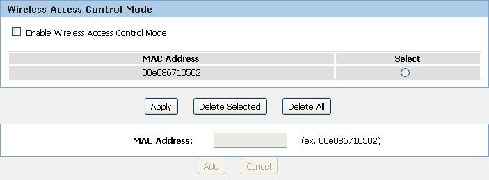
61 Disable PIN (For AP Mode only) Keep current configuration (For AP Mode only) Disable or Enable PIN Disable or Enable current configuration Wireless Access Control Mode For security reason, using MAC ACL's (MAC Address Access List) creates another level of difficulty to hacking a network. A MAC ACL is created and distributed to AP so that only authorized NIC's can connect to the network. While MAC address spoofing is a proven means to hacking a network this can be used in conjunction with additional security measures to increase the level of complexity of the network security decreasing the chance of a breach. MAC addresses can be add/delete/edit from the ACL list depending on the MAC Access Policy. If you choose 'Allowed Listed', only those clients whose wireless MAC addresses are in the access control list will be able to connect to your Access Point. When 'Deny Listed' is selected, these wireless clients on the list will not be able to connect the Access Point. To access the Wireless Network Access Control page: From the Wireless menu, click on Wireless Advanced and then click on ACL Setup button. The following page is displayed: Allow Listed If you Enable Wireless Access Control Mode, only those clients whose wireless MAC addresses are in the access control list will be able to connect to your Access Point. 1. Enable Wireless Access Control Mode. 2. Click Apply button. 61


62 3. Click OK button. 4. Enter the MAC Address. 5. Click Add button. 6. The MAC Address that you created has been added in the Access Control List. 62
63 63

64 11 Reboot/Reset Restarts the device with current setting or default setting. Reboot/Reset 1. From the Maintenance -> Reboot menu. The following page is displayed: Fields on the first setting block Reboot Reset Description Restarts the router for the settings to take effect. Restarts the router with factory default setting. 64

65 12 Firmware Upgrade About firmware versions Firmware is a software program. It is stored as read-only memory on your device. Your device can check whether there are later firmware versions available. If there is a later version, you can download it via the Internet and install it on your device. Note If there is a firmware update available you are strongly advised to install it on your device to ensure that you take full advantage of any new feature developments. Manually updating firmware You can manually download the latest firmware version from provider s website to your PC s file directory. Once you have downloaded the latest firmware version to your PC, you can manually select and install it as follows: 1. From the Maintenance -> Firmware Upgrade menu. The following page is displayed: 2. Click on the Browse button. 3. Once you have selected the file to be installed, click Open. The file s directory path is displayed in the New Firmware Image: text box. 4. Click Automatically reset default after firmware upgraded. 5. Click Upload. Figure 6: Manual Update Installation section (Note that if you are using certain browsers (such as Opera 7) the Browse button is labeled Choose.) Use the Choose file box to navigate to the relevant directory where the firmware version is saved. 65

66 6. Click OK. 7. The device checks that the selected file contains an updated version of firmware. A status screen pops up, please wait for a while. 8. The device checks that the selected file contains an updated version of firmware. A status screen pops up, please wait for a while. 66
67 13 Backup/Restore Settings This page allows you save current settings to a file or reload the settings from the file which was saved previously. Besides, you could reset the current configuration to factory default. If you do make changes to the default configuration but then wish to revert back to the original factory configuration, you can do so by resetting the device to factory defaults. Save Settings to File It allows you save current settings to a file. 1. From the Maintenance -> Backup/Restore menu. The following page is displayed: Figure 7: Reset to Defaults page Option Description Save Settings to File Load Settings from File Save the Settings to a File Load Settings from a File 2. Click on Save. 67

68 3. If you are happy with this, click Save and then browse to where the file to be saved. Or click Cancel to cancel it. Load Settings from File It allows you to reload the settings from the file which was saved previously. 4. From the Maintenance -> Backup/Restore menu. The following page is displayed: 5. Click on Browse.to browse to where the config.img is. 68
69 6. If you are happy with this, click Upload to start to load settings from file. 7. If you are happy with this, click Upload to start to load settings from file. 8. please wait for a while. 69

70 14 Password You can restrict access to your device s web pages using password protection. With password protection enabled, users must enter a username and password before gaining access to the web pages. By default, password protection is enabled on your device, and the username and password set are as follows: Username: admin Password: administrator Setting your username and password Note Non-authorized users may try to access your system by guessing your username and password. We recommend that you change the default username and password to your own unique settings. To change the default password: 1. From the Maintenance -> Password menu. The following page is displayed: 70

71 2. This page displays the current username and password settings. Change your own unique password in the relevant boxes. They can be any combination of letters or numbers with a maximum of 30 characters. The default setting uses admin for the username and administrator for password. 3. If you are happy with these settings, click Modify. You will see following page that the new user has been displayed on the Currently Defined Users. You need to login to the web pages using your new username and new password. 4. Click on the ratio of admin from User Account Table. 5. Enter the Old Password. 6. Enter the New Password. 7. Enter the Confirm Password. 8. Click on Modify. 71
. 1. From the Status -> Device Info menu.")
72 15 Status This page displays the current information for the device. It will display the LAN, WAN, and system firmware information. This page will display different information, according to WAN setting (Static IP, DHCP, or PPPoE). 1. From the Status -> Device Info menu. The following page is displayed: 72

73 16 Active Client Table This page shows the computers, identified by the name and MAC address that have acquired IP addresses by the DHCP server with the time that the lease for the IP address is up 1. From the Status -> Active Client Table menu. The following page is displayed: 73

74 17 Statistics This page shows the packet statistics for transmission and reception regarding to network interface. 1. From the Status -> Statistics menu. The following page is displayed: 74
75 A Configuring your Computers This appendix provides instructions for configuring the Internet settings on your computers to work with the Wireless Gateway. Configuring Ethernet PCs Before you begin By default, the Wireless Gateway automatically assigns the required Internet settings to your PCs. You need to configure the PCs to accept this information when it is assigned. Note In some cases, you may want to assign Internet information manually to some or all of your computers rather than allow the Wireless Gateway to do so. See Assigning static Internet information to your PCs for instructions. If you have connected your LAN PCs via Ethernet to the Wireless Gateway, follow the instructions that correspond to the operating system installed on your PC: Windows XP PCs Windows 2000 PCs Windows Me PCs Windows 95, 98 PCs Windows NT 4.0 workstations Windows XP PCs 1. In the Windows task bar, click the Start button, and then click Control Panel. 2. Double-click the Network Connections icon. 3. In the LAN or High-Speed Internet window, right-click on the icon corresponding to your network interface card (NIC) and select Properties. (Often, this icon is labeled Local Area Connection). The Local Area Connection dialog box is displayed with a list of currently installed network items. 4. Ensure that the check box to the left of the item labeled Internet Protocol TCP/IP is checked and click Properties. 5. In the Internet Protocol (TCP/IP) Properties dialog box, click the radio button labeled Obtain an IP address automatically. Also click the radio button labeled Obtain DNS server address automatically. 6. Click OK twice to confirm your changes, and then close the Control Panel. Windows 2000 PCs First, check for the IP protocol and, if necessary, install it: 1. In the Windows task bar, click the Start button, point to Settings, and then click Control Panel. 2. Double-click the Network and Dial-up Connections icon. 75
76 3. In the Network and Dial-up Connections window, right-click the Local Area Connection icon, and then select Properties. The Local Area Connection Properties dialog box is displayed with a list of currently installed network components. If the list includes Internet Protocol (TCP/IP), then the protocol has already been enabled. Skip to step If Internet Protocol (TCP/IP) does not display as an installed component, click Install 5. In the Select Network Component Type dialog box, select Protocol, and then click Add 6. Select Internet Protocol (TCP/IP) in the Network Protocols list, and then click OK. You may be prompted to install files from your Windows 2000 installation CD or other media. Follow the instructions to install the files. 7. If prompted, click OK to restart your computer with the new settings. Next, configure the PCs to accept IP information assigned by the Wireless Gateway: 8. In the Control Panel, double-click the Network and Dial-up Connections icon. 9. In the Network and Dial-up Connections window, right-click the Local Area Connection icon, and then select Properties. 10. In the Local Area Connection Properties dialog box, select Internet Protocol (TCP/IP), and then click Properties. 11. In the Internet Protocol (TCP/IP) Properties dialog box, click the radio button labeled Obtain an IP address automatically. Also click the radio button labeled Obtain DNS server address automatically. 12. Click OK twice to confirm and save your changes, and then close the Control Panel. 76
77 Windows Me PCs 1. In the Windows task bar, click the Start button, point to Settings, and then click Control Panel. 2. Double-click the Network and Dial-up Connections icon. 3. In the Network and Dial-up Connections window, right-click the Network icon, and then select Properties. The Network Properties dialog box displays with a list of currently installed network components. If the list includes Internet Protocol (TCP/IP), then the protocol has already been enabled. Skip to step If Internet Protocol (TCP/IP) does not display as an installed component, click Add 5. In the Select Network Component Type dialog box, select Protocol, and then click Add 6. Select Microsoft in the Manufacturers box. 7. Select Internet Protocol (TCP/IP) in the Network Protocols list, and then click OK. You may be prompted to install files from your Windows Me installation CD or other media. Follow the instructions to install the files. 8. If prompted, click OK to restart your computer with the new settings. Next, configure the PCs to accept IP information assigned by the Wireless Gateway: 9. In the Control Panel, double-click the Network and Dial-up Connections icon. 10. In Network and Dial-up Connections window, right-click the Network icon, and then select Properties. 11. In the Network Properties dialog box, select TCP/IP, and then click Properties. 12. In the TCP/IP Settings dialog box, click the radio button labeled Server assigned IP address. Also click the radio button labeled Server assigned name server address. 13. Click OK twice to confirm and save your changes, and then close the Control Panel. Windows 95, 98 PCs First, check for the IP protocol and, if necessary, install it: 1. In the Windows task bar, click the Start button, point to Settings, and then click Control Panel. 2. Double-click the Network icon. The Network dialog box displays with a list of currently installed network components. If the list includes TCP/IP, and then the protocol has already been enabled. Skip to step If TCP/IP does not display as an installed component, click Add The Select Network Component Type dialog box displays. 4. Select Protocol, and then click Add The Select Network Protocol dialog box displays. 77
78 5. Click on Microsoft in the Manufacturers list box, and then click TCP/IP in the Network Protocols list box. 6. Click OK to return to the Network dialog box, and then click OK again. You may be prompted to install files from your Windows 95/98 installation CD. Follow the instructions to install the files. 7. Click OK to restart the PC and complete the TCP/IP installation. Next, configure the PCs to accept IP information assigned by the Wireless Gateway: 8. Open the Control Panel window, and then click the Network icon. 9. Select the network component labeled TCP/IP, and then click Properties. If you have multiple TCP/IP listings, select the listing associated with your network card or adapter. 10. In the TCP/IP Properties dialog box, click the IP Address tab. 11. Click the radio button labeled Obtain an IP address automatically. 12. Click the DNS Configuration tab, and then click the radio button labeled Obtain an IP address automatically. 13. Click OK twice to confirm and save your changes. You will be prompted to restart Windows. 14. Click Yes. Windows NT 4.0 workstations First, check for the IP protocol and, if necessary, install it: 1. In the Windows NT task bar, click the Start button, point to Settings, and then click Control Panel. 2. In the Control Panel window, double click the Network icon. 3. In the Network dialog box, click the Protocols tab. The Protocols tab displays a list of currently installed network protocols. If the list includes TCP/IP, then the protocol has already been enabled. Skip to step If TCP/IP does not display as an installed component, click Add 5. In the Select Network Protocol dialog box, select TCP/IP, and then click OK. You may be prompted to install files from your Windows NT installation CD or other media. Follow the instructions to install the files. After all files are installed, a window displays to inform you that a TCP/IP service called DHCP can be set up to dynamically assign IP information. 6. Click Yes to continue, and then click OK if prompted to restart your computer. Next, configure the PCs to accept IP information assigned by the Wireless Gateway: 78
79 7. Open the Control Panel window, and then double-click the Network icon. 8. In the Network dialog box, click the Protocols tab. 9. In the Protocols tab, select TCP/IP, and then click Properties. 10. In the Microsoft TCP/IP Properties dialog box, click the radio button labeled Obtain an IP address from a DHCP server. 11. Click OK twice to confirm and save your changes, and then close the Control Panel. Assigning static Internet information to your PCs If you are a typical user, you will not need to assign static Internet information to your LAN PCs because your ISP automatically assigns this information for you. In some cases however, you may want to assign Internet information to some or all of your PCs directly (often called statically ), rather than allowing the Wireless Gateway to assign it. This option may be desirable (but not required) if: You have obtained one or more public IP addresses that you want to always associate with specific computers (for example, if you are using a computer as a public web server). You maintain different subnets on your LAN (subnets are described in Appendix B). Before you begin, you must have the following information available: The IP address and subnet mask of each PC The IP address of the default gateway for your LAN. In most cases, this is the address assigned to the LAN port on the Wireless Gateway. By default, the LAN port is assigned the IP address (You can change this number or another number can be assigned by your ISP. See Addressing for more information.) The IP address of your ISP s Domain Name System (DNS) server. On each PC to which you want to assign static information, follow the instructions relating only to checking for and/or installing the IP protocol. Once it is installed, continue to follow the instructions for displaying each of the Internet Protocol (TCP/IP) properties. Instead of enabling dynamic assignment of the IP addresses for the computer, DNS server and default gateway, click the radio buttons that enable you to enter the information manually. Note Your PCs must have IP addresses that place them in the same subnet as the Wireless Gateway s LAN port. If you manually assign IP information to all your LAN PCs, you can follow the instructions in Addressing to change the LAN port IP address accordingly. 79
80
81 B IP Addresses, Network Masks, and Subnets IP Addresses This section refers only to IP addresses for IPv4 (version 4 of the Internet Protocol). IPv6 addresses are not covered. Note This section assumes basic knowledge of binary numbers, bits, and bytes. IP addresses, the Internet's version of telephone numbers, are used to identify individual nodes (computers or devices) on the Internet. Every IP address contains four numbers, each from 0 to 255 and separated by dots (periods), e.g These numbers are called, from left to right, field1, field2, field3, and field4. This style of writing IP addresses as decimal numbers separated by dots is called dotted decimal notation. The IP address is read "twenty dot fifty-six dot zero dot two-eleven." Structure of an IP address IP addresses have a hierarchical design similar to that of telephone numbers. For example, a 7-digit telephone number starts with a 3-digit prefix that identifies a group of thousands of telephone lines, and ends with four digits that identify one specific line in that group. Similarly, IP addresses contain two kinds of information: Network ID Identifies a particular network within the Internet or intranet Host ID Identifies a particular computer or device on the network The first part of every IP address contains the network ID, and the rest of the address contains the host ID. The length of the network ID depends on the network's class (see following section). The table below shows the structure of an IP address. Field1 Field2 Field3 Field4 Class A Network ID Host ID Class B Network ID Host ID Class C Network ID Host ID Here are some examples of valid IP addresses: Class A: (network = 10, host = ) Class B: (network = , host = 16.49) Class C: (network = , host = 11) Network classes The three commonly used network classes are A, B, and C. (There is also a class D but it has a special use beyond the 81
82 scope of this discussion.) These classes have different uses and characteristics. Class A networks are the Internet's largest networks, each with room for over 16 million hosts. Up to 126 of these huge networks can exist, for a total of over 2 billion hosts. Because of their huge size, these networks are used for WANs and by organizations at the infrastructure level of the Internet, such as your ISP. Class B networks are smaller but still quite large, each able to hold over 65,000 hosts. There can be up to 16,384 class B networks in existence. A class B network might be appropriate for a large organization such as a business or government agency. Class C networks are the smallest, only able to hold 254 hosts at most, but the total possible number of class C networks exceeds 2 million (2,097,152 to be exact). LANs connected to the Internet are usually class C networks. Some important notes regarding IP addresses: The class can be determined easily from field1: field1 = 1-126: Class A field1 = : Class B field1 = : Class C (field1 values not shown are reserved for special uses) A host ID can have any value except all fields set to 0 or all fields set to 255, as those values are reserved for special uses. Subnet masks Definition mask A mask looks like a regular IP address, but contains a pattern of bits that tells what parts of an IP address are the network ID and what parts are the host ID: bits set to 1 mean "this bit is part of the network ID" and bits set to 0 mean "this bit is part of the host ID." Subnet masks are used to define subnets (what you get after dividing a network into smaller pieces). A subnet's network ID is created by "borrowing" one or more bits from the host ID portion of the address. The subnet mask identifies these host ID bits. For example, consider a class C network To split this into two subnets, you would use the subnet mask: It's easier to see what's happening if we write this in binary: As with any class C address, all of the bits in field1 through field3 are part of the network ID, but note how the mask specifies that the first bit in field4 is also included. Since this extra bit has only two values (0 and 1), this means there are two subnets. Each subnet uses the remaining 7 bits in field4 for its host IDs, which range from 1 to 126 hosts (instead of the usual 0 to 255 for a class C address). Similarly, to split a class C network into four subnets, the mask is: 82
83 or The two extra bits in field4 can have four values (00, 01, 10, 11), so there are four subnets. Each subnet uses the remaining six bits in field4 for its host IDs, ranging from 1 to 62. Note Sometimes a subnet mask does not specify any additional network ID bits, and thus no subnets. Such a mask is called a default subnet mask. These masks are: Class A: Class B: Class C: These are called default because they are used when a network is initially configured, at which time it has no subnets. 83
84 C UPnP Control Point Software on Windows ME/XP This appendix provides instructions for configuring the UPnP on your computers to work with the Wireless Gateway. UPnP is an architecture for pervasive peer-to-peer network connectivity of intelligent appliances, Wireless devices, and PCs of all form factors. It is designed to bring easy-to-use, flexible, standards-based connectivity to ad-hoc or unmanaged networks whether in the home, in a small business, public spaces, or attached to the Internet. UPnP is a distributed, open networking architecture that leverages TCP/IP and the Web technologies to enable seamless proximity networking in addition to control and data transfer among networked devices in the home, office, and public spaces. UPnP is more than just a simple extension of the plug and play peripheral model. It is designed to support zero-configuration, "invisible" networking, and automatic discovery for a breadth of device categories from a wide range of vendors. This means a device can dynamically join a network, obtain an IP address, convey its capabilities, and learn about the presence and capabilities of other devices. DHCP and DNS servers are optional and are used only if available on the network. Finally, a device can leave a network smoothly and automatically without leaving any unwanted state behind. UPnP Control Point Software on Windows ME To install the control point software on Windows ME: 1. In the Control Panel, select "Add/Remove Programs". 2. In the "Add/Remove Programs Properties" dialog box, select the "Windows Setup" tab. In the "Components" list, double click on the "Communications" entry. 3. In the "Communications" dialog box, scroll down the "Components" list to display the UPnP entry. Select the entry, click "OK". 4. Click "OK" to finish the "Add/Remove Programs" dialog. 5. Reboot your system. Once you have installed the UPnP software and you have rebooted (and your network includes the IGD system), you should be able to see the IGD controlled device on your network. 84
85 UPnP Control Point Software on Windows XP with Firewall On Windows XP versions earlier than SP2, Firewall support is provided by the Windows XP Internet Connection Firewall. You cannot use the Windows XP Internet Connection Firewall support on a system that you intend to use as a UPnP control point. If this feature is enabled, although the control point system may display controlled devices in the list of network devices, the control point system cannot participate in UPnP communication. (This restriction also applies to controlled devices running on Windows XP systems earlier than SP2.) On Windows XP SP2 and later, Firewall support is provided by Windows Firewall. Unlike earlier versions, Windows XP SP2 can be used on a system that you intend to use as a UPnP control point. To turn off the Firewall capability on any version of Windows XP, follow the steps below: 1. In the Control Panel, select "Network and Internet Connections". 2. In the "Network and Internet Connections" dialog box, select "Network Connections". 3. In the "Network Connections" dialog box, right-click on the local area connection entry for your network; this will display a menu. Select the "Properties" menu entry. 4. In the "Local Area Connection Properties" dialog box, select the "Advanced" tab. Disable the Internet Connection Firewall by de-selecting the entry with the following label: "Protect my computer and network by limiting or preventing access to the computer from the Internet". 5. Click "OK". SSDP requirements You must have SSDP Discovery Service enabled on your Windows XP system to use the UPnP Control point software. SSDP Discovery Service is enabled on a default installation of Windows XP. To check if it is enabled on your system, look in Control Panel > Administrative Tools > Services). Installation procedure To install the Control point software on Windows XP, follow the steps below: 1. In the Control Panel, select "Add/Remove Programs". 2. In the "Add or Remove Programs" dialog box, click the "Add / Remove Windows Components" button. 3. In the "Windows Component Wizard" dialog box, scroll down the list to display the "Networking Services" entry. Highlight (select) the entry, and click on the "Details" button. 85
, or Windows XP (SP2).")
86 4. The Networking Services window is displayed. The subcomponents shown in the Networking Services window will be different depending on if you are using Windows XP, Windows XP (SP1), or Windows XP (SP2). If you are using Windows XP SP2, the Networking Services window will display the following list of sub-components: 5. Select the following entries from the Networking Services window and then click "OK": If you are using Windows XP, select: "Universal Plug and Play". If you are using Windows XP SP1, select: "Internet Gateway Device discovery and Control Client". "Universal Plug and Play". If you are using Windows XP SP2, select: "Internet Gateway Device discovery and Control Client". "UPnP User Interface". 6. Reboot your system. Once you have installed the UPnP software and you have rebooted (and your network includes the IGD system), you should be able to see the IGD controlled device on your network. 86

87 For example, from the Network Connections window you should see the Internet Gateway Device: 87
88 錯誤! 使用 [ 常用 ] 索引標籤將 Title 套用到您想要在此處顯示的文字 User s Guide Troubleshooting D Troubleshooting This appendix suggests solutions for problems you may encounter in installing or using the Wireless Gateway, and provides instructions for using several IP utilities to diagnose problems. Contact Customer Support if these suggestions do not resolve the problem. Troubleshooting Suggestions Problem LEDs Power LED does not illuminate after product is turned on. LINK LAN LED does not illuminate after Ethernet cable is attached. Internet Access My PC cannot access the Internet My LAN PCs cannot display web pages on the Internet. Web pages Troubleshooting Suggestion Verify that you are using the power cable provided with the device and that it is securely connected to the Wireless Gateway and a wall socket/power strip. Verify that the Ethernet cable is securely connected to your LAN hub or PC and to the Wireless Gateway. Make sure the PC and/or hub is turned on. Verify that your cable is sufficient for your network requirements. A 100 Mbit/sec network (10BaseTx) should use cables labeled CAT 5. A 10Mbit/sec network may tolerate lower quality cables. Use the ping utility (discussed in the following section) to check whether your PC can communicate with the device s LAN IP address (by default ). If it cannot, check the Ethernet cabling. If you statically assigned a private IP address to the computer, (not a registered public address), verify the following: Check that the gateway IP address on the computer is your public IP address (see Current Status for instructions on viewing the IP information.) If it is not, correct the address or configure the PC to receive IP information automatically. Verify with your ISP that the DNS server specified for the PC is valid. Correct the address or configure the PC to receive this information automatically. Verify that the DNS server IP address specified on the PCs is correct for your ISP, as discussed in the item above. If you specified that the DNS server be assigned dynamically from a server, then verify with your ISP that the address configured on the Wireless Gateway is correct, then You can use the ping utility, to test connectivity with your ISP s DNS server.
89 Problem I forgot/lost my user ID or password. I cannot access the web pages from my browser. My changes to the web pages are not being retained. Troubleshooting Suggestion If you have not changed the password from the default, try using admin the user ID and administrator as password. Otherwise, you can reset the device to the default configuration by pressing the Reset Default button on the Rare panel of the device (see Rare Panel). Then, type the default User ID and password shown above. WARNING: Resetting the device removes any custom settings and returns all settings to their default values. Use the ping utility, discussed in the following section, to check whether your PC can communicate with the device s LAN IP address (by default ). If it cannot, check the Ethernet cabling. Verify that you are using Internet Explorer or Netscape Navigator v4.0 or later. Verify that the PC s IP address is defined as being on the same subnet as the IP address assigned to the LAN port on the Wireless Gateway. Be sure to use the Confirm Changes/Apply function after any changes. 89

90 Diagnosing Problem using IP Utilities ping Ping is a command you can use to check whether your PC can recognize other computers on your network and the Internet. A ping command sends a message to the computer you specify. If the computer receives the message, it sends messages in reply. To use it, you must know the IP address of the computer with which you are trying to communicate. On Windows-based computers, you can execute a ping command from the Start menu. Click the Start button, and then click Run. In the Open text box, type a statement such as the following: ping Click OK. You can substitute any private IP address on your LAN or a public IP address for an Internet site, if known. If the target computer receives the message, a Command Prompt window is displayed: Figure 8: Using the ping Utility If the target computer cannot be located, you will receive the message Request timed out. Using the ping command, you can test whether the path to the Wireless Gateway is working (using the preconfigured default LAN IP address ) or another address you assigned. You can also test whether access to the Internet is working by typing an external address, such as that for ( ). If you do not know the IP address of a particular Internet location, you can use the nslookup command, as explained in the following section. From most other IP-enabled operating systems, you can execute the same command at a command prompt or through a system administration utility. nslookup You can use the nslookup command to determine the IP address associated with an Internet site name. You specify the common name, and the nslookup command looks up the name in on your DNS server (usually located with your ISP). If that 90

91 name is not an entry in your ISP s DNS table, the request is then referred to another higher-level server, and so on, until the entry is found. The server then returns the associated IP address. On Windows-based computers, you can execute the nslookup command from the Start menu. Click the Start button, and then click Run. In the Open text box, type the following: Nslookup Click OK. A Command Prompt window displays with a bracket prompt (>). At the prompt, type the name of the Internet address that you are interested in, such as The window will display the associate IP address, if known, as shown below: Figure 9: Using the nslookup Utility There may be several addresses associated with an Internet name. This is common for web sites that receive heavy traffic; they use multiple, redundant servers to carry the same information. To exit from the nslookup utility, type exit and press [Enter] at the command prompt. 91
802.11n WLAN Portable Repeater
 802.11n WLAN Portable Repeater User s Manual 1 Table of Contents 1 Introduction... 6 Features... 6 Device Requirements... 6 Using this Document... 7 Notational conventions... 7 Typographical conventions...
LevelOne User Manual WGR-8031
 LevelOne User Manual WGR-8031 Version : v1.0_20160321 1 Table of Contents 1 Introduction... 9 Features... 9 Device Requirements... 9 Using this Document... 10 Notational conventions... 10 Typographical
WELL WRC5020N User s Manual WELL WRC5020N. User s Manual
 WELL WRC5020N User s Manual 1 Table of Contents 1 Introduction... 7 Features... 7 Device Requirements... 7 Using this Document... 8 Notational conventions... 8 Typographical conventions... 8 Special messages...
802.11N Wireless Broadband Router
 802.11N Wireless Broadband Router Pre-N Wireless Access Point Broadband Internet Access WPS 4-Port Switching Hub User's Guide Table of Contents CHAPTER 1 INTRODUCTION... 1 Wireless Router Features... 1
Wireless-G Router User s Guide
 Wireless-G Router User s Guide 1 Table of Contents Chapter 1: Introduction Installing Your Router System Requirements Installation Instructions Chapter 2: Preparing Your Network Preparing Your Network
AirCruiser G Wireless Router GN-BR01G
 AirCruiser G Wireless Router GN-BR01G User s Guide i Contents Chapter 1 Introduction... 1 Overview...1 Features...1 Package Contents...2 AirCruiser G Wireless Router Rear Panel...2 AirCruiser G Wireless
Wireless b/g/n 150Mbps AP Router
 Wireless 802.11b/g/n 150Mbps AP Router User Manual V1.2 2009-11-30 Package Contents The following items should be found in your package: One Wireless 802.11b/g/n 150Mbps Broadband Router One DC 9v power
IP806GA/GB Wireless ADSL Router
 IP806GA/GB Wireless ADSL Router 802.11g/802.11b Wireless Access Point ADSL Modem NAT Router 4-Port Switching Hub User's Guide Table of Contents CHAPTER 1 INTRODUCTION... 1 Wireless ADSL Router Features...
MIMO Wireless Broadband Route r User s Manual 1
 MIMO Wireless Broadband Router User s Manual 1 Introduction...4 Features...4 Minimum Requirements...4 Package Content...4 Note...4 Get to know the Broadband Router...5 Back Panel...5 Front Panel...6 Setup
CHAPTER 7 ADVANCED ADMINISTRATION PC
 ii Table of Contents CHAPTER 1 INTRODUCTION... 1 Broadband ADSL Router Features... 1 Package Contents... 3 Physical Details... 4 CHAPTER 2 INSTALLATION... 6 Requirements... 6 Procedure... 6 CHAPTER 3 SETUP...
Wireless Broadband Router
 LW6005A-R2 Wireless Broadband Router Manual 1 Introduction... 4 Features... 4 Minimum Requirements... 4 Package Content... 4 Note... 4 Get to know the Broadband Router... 5 Back Panel... 5 Front Panel...
Conceptronic C100BRS4H Quick Installation Guide. Congratulations on the purchase of your Conceptronic 4-ports Broadband Router.
 Conceptronic C100BRS4H Quick Installation Guide Congratulations on the purchase of your Conceptronic 4-ports Broadband Router. The enclosed Hardware Installation Guide gives you a step-by-step explanation
D-Link AirPlus G DWL-G700AP
 TM D-Link AirPlus G DWL-G700AP 2.4GHz Wireless Access Point Manual Building Networks for People Contents Package Contents...3 Introduction...4 Wireless Basics...6 Getting Started...8 Using the Configuration
CWA-854HT 54 Mbps Wireless-G High Transmission Access Point User s Guide
 CWA-854HT 54 Mbps Wireless-G High Transmission Access Point User s Guide May 2006 Version 1.00 1 Table of Contents Table of Contents... 2 List of Figures... 4 List of Tables... 6 Chapter 1. Introduction...
WRE2206. User s Guide. Quick Start Guide. Wireless N300 Range Extender. Default Details. Version 1.00 Edition 1, 01/2015
 WRE2206 Wireless N300 Range Extender Version 1.00 Edition 1, 01/2015 Quick Start Guide User s Guide Default Details Web Address http://zyxelsetup OR http://192.168.1.2 www.zyxel.com User Name admin Password
Introduction... 3 Features... 3 Minimum Requirements... 3 Package Content... 3 Note... 3 Get to know the Broadband Router... 4 Back Panel...
 Introduction... 3 Features... 3 Minimum Requirements... 3 Package Content... 3 Note... 3 Get to know the Broadband Router... 4 Back Panel... 4 Front Panel... 5 Setup Diagram... 6 Getting started... 7 Chapter
Content 1 OVERVIEW HARDWARE DESCRIPTION HARDWARE INSTALLATION PC CONFIGURATION GUIDE... 5 WEB-BASED MANAGEMENT GUIDE...
 Content 1 OVERVIEW...1 1.1FEATURES...1 1.2 PACKETCONTENTS...3 1.3 SYSTEM REQUIREMENTS... 1.4 FACTORY DEFAULTS...4 1.5 WARNINGS AND CAUTIONS...4 2 HARDWARE DESCRIPTION... 6 3 HARDWARE INSTALLATION...8 4
satspeed V7621-A1 VDSL2/ADSL2+ IAD
 satspeed V7621-A1 User s Manual satspeed V7621-A1 VDSL2/ADSL2+ IAD satspeed V7621-A1 VDSL2/ADSL2+ IAD User s Manual 1 satspeed V7621-A1 User s Manual Table of Contents 1 Introduction... 9 Features... 9
Introduction... 3 Features... 3 Minimum Requirements... 3 Package Content... 3 Note... 3 Get to know the Broadband Router... 4 Back Panel...
 Introduction... 3 Features... 3 Minimum Requirements... 3 Package Content... 3 Note... 3 Get to know the Broadband Router... 4 Back Panel... 4 Front Panel... 5 Setup Diagram... 6 Getting started... 7 Chapter
Wireless ADSL2+ Router
 Wireless ADSL2+ Router User s Guide Wireless ADSL2+ Router User s Manual 1 Wireless ADSL2+ Router User s Guide Table of Contents 1 Introduction... 8 Features... 8 Device Requirements... 8 Using this Document...
NBG-416N. Wireless N-lite Home Router. Default Login Details. IMPORTANT! READ CAREFULLY BEFORE USE.
 NBG-416N Wireless N-lite Home Router IMPORTANT! Default Login Details LAN IP https://192.168.1.1 Address User Name admin Password 1234 READ CAREFULLY BEFORE USE. KEEP THIS GUIDE FOR FUTURE REFERENCE. IMPORTANT!
300M Wireless-N Broadband Router User Manual
 300M Wireless-N Broadband Router Model No.: ib-wrb314n User Manual Ver.: 1.0.0 Contents...Error! Bookmark not defined. Chapter 1 Product Overview... 3 Package Contents 3 Conventions....4 Panel Overview...
802.11N Wireless ADSL Router
 802.11N Wireless ADSL Router Pre-N Wireless Access Point ADSL Modem NAT Router WPS 4-Port Switching Hub User's Guide Table of Contents CHAPTER 1 INTRODUCTION...1 Wireless ADSL Router Features...1 Package
Broadband Router DC 202
 Broadband Router DC 202 Full Manual Table of Contents DC-202 xdsl/cable Broadband router REQUIREMENTS...4 INTRODUCTION...4 DC-202 Features...4 Internet Access Features...4 Advanced Internet Functions...5
User Manual DIR-615. Wireless Router with Built-in 4-port Switch
 DIR-615 Wireless Router with Built-in 4-port Switch December 2011 Contents Chapter 1. Introduction...4 Contents and Audience...4 Conventions...4 Document Structure...4 Chapter 2. Overview...5 General Information...5
DRG600-WIFI USER GUIDE
 DRG600-WIFI USER GUIDE P/N: DFB601CW Copyright 2008. All Rights Reserved. Printed May 15, 2008 All trademarks and trade names are the properties of their respective owners. Page 2 of 104 Contents INTRODUCTION...
Broadband Router DC-202. User's Guide
 Broadband Router DC-202 User's Guide Table of Contents CHAPTER 1 INTRODUCTION... 1 Broadband Router Features... 1 Package Contents... 3 Physical Details...3 CHAPTER 2 INSTALLATION... 5 Requirements...
54Mbps Pocket Wireless Access Point (WL-330g)
") 54Mbps Pocket Wireless Access Point (WL-330g) Copyright 2004 ASUSTeK COMPUTER INC. All Rights Reserved. Contents Conventions... 2 Welcome!... 3 Package contents... 3 System requirements... 3 Device installation...
54Mbps Pocket Wireless Access Point (WL-330g) Copyright 2004 ASUSTeK COMPUTER INC. All Rights Reserved. Contents Conventions... 2 Welcome!... 3 Package contents... 3 System requirements... 3 Device installation...
TCP/IP CONFIGURATION 3-6
 TCP/IP CONFIGURATION 3. Type IPCONFIG /RENEW and press the Enter key. Verify that your IP Address is now 192.168.2.xxx, your Subnet Mask is 255.255.255.0 and your Default Gateway is 192.168.2.1. These
LevelOne WBR User s Manual. 11g Wireless ADSL VPN Router. Ver
 LevelOne WBR-3407 11g Wireless ADSL VPN Router User s Manual Ver 1.00-0510 Table of Contents CHAPTER 1 INTRODUCTION... 1 Wireless ADSL Router Features... 1 Package Contents... 5 Physical Details... 6 CHAPTER
WAP3205 v2. User s Guide. Quick Start Guide. Wireless N300 Access Point. Default Login Details. Version 1.00 Edition 2, 12/2012
 WAP3205 v2 Wireless N300 Access Point Version 1.00 Edition 2, 12/2012 Quick Start Guide User s Guide Default Login Details LAN IP Address http://192.168.1.2 Password 1234 www.zyxel.com Copyright 2012 ZyXEL
NBG-418N. Wireless N Home Router. Default Login Details. IMPORTANT! READ CAREFULLY BEFORE USE. KEEP THIS GUIDE FOR FUTURE REFERENCE.
 NBG-418N Wireless N Home Router IMPORTANT! Default Login Details LAN IP http://192.168.1.1 Address User Name admin Password 1234 READ CAREFULLY BEFORE USE. KEEP THIS GUIDE FOR FUTURE REFERENCE. IMPORTANT!
User Manual. Rev:
 Default Login Details Login Address: www.mykasda.com Login Password: Set up by users Default Wi-Fi SSID: Kasda xxxx KW6516 (Printed on product label) Default Wi-Fi Password: 12345678 www.kasdanet.com Rev:
ADDON Magic r9500 Wireless Router User Manual V1.0
 ADDON Magic r9500 Wireless Router User Manual V1.0 Contents 1 Safety Precautions... 3 2 Overview... 4 2.1 Product Introduction... 4 2.2 Packing list... 4 3 Hardware and Hardware Installation... 5 3.1 Front
BiPAC 3100SN Wireless-N Wall Plug Ethernet Access Point User Manual
 BiPAC 3100SN Wireless-N Wall Plug Ethernet Access Point User Manual FW version 1.05-c Last revised on Jun 2010 Safety Warnings 1. Do not use the adapter in high humidity or high temperature environment.
User Manual DIR-850L. Wireless AC1200 Dual Band Gigabit Router.
 User Manual DIR-850L Wireless AC1200 Dual Band Gigabit Router USER MANUAL: DIR-850L Wireless AC1200 Dual Band Gigabit Router SYSTEM REQUIREMENTS Network Requirements Web-based Configuration Utility Requirements
WL5041 Router User Manual
 TECOM WL5041 Router User Manual TECOM CO., LTD. March 2003 2003 by TECOM CO., LTD. All rights reserved. Printed in Taiwan Table of contents Package Contents--------------------------------------- 2 Installing
LevelOne FBR User s Manual. 1W, 4L 10/100 Mbps ADSL Router. Ver
 LevelOne FBR-1416 1W, 4L 10/100 Mbps ADSL Router User s Manual Ver 1.00-0510 Table of Contents CHAPTER 1 INTRODUCTION... 1 FBR-1416 Features... 1 Package Contents... 3 Physical Details... 3 CHAPTER 2
Multi-Function Wireless Router. User's Guide. Wireless Access Point Broadband Internet Access. 4-Port Switching Hub
 Multi-Function Wireless Router Wireless Access Point Broadband Internet Access 4-Port Switching Hub User's Guide Table of Contents CHAPTER 1 INTRODUCTION... 1 Wireless Router Features... 1 Package Contents...
User Guide. 450Mbps/300Mbps Wireless N Access Point TL-WA901ND/TL-WA801ND REV
 User Guide 450Mbps/300Mbps Wireless N Access Point TL-WA901ND/TL-WA801ND REV4.0.0 1910011930 Contents About This Guide...1 Chapter 1. Get to Know About Your Access Point.................... 2 1. 1. Product
TEW-211BRP. Wireless AP Router. User s Manual
 TEW-211BRP Wireless AP Router User s Manual Version 1.4 - Jan 2002 CONTENTS Introduction...3 Hardware Installation...5 General Wireless AP Router System Connection...6 Wireless AP Router Default Settings
Wireless USB Port Multi-Functional Printer Server. Model # AMPS240W. User s Manual. Ver. 1A
 Wireless USB 2.0 1-Port Multi-Functional Printer Server Model # AMPS240W User s Manual Ver. 1A Table of Contents 1 Introduction...3 1.1 Package Contents... 3 1.2 System Requirements... 3 2 Multi-Functional
Wireless a CPE User Manual
 NOTICE Changes or modifications to the equipment, which are not approved by the party responsible for compliance, could affect the user's authority to operate the equipment. Company has an on-going policy
KW55293 Wireless Router. User Manual
 NOTICE This document contains proprietary information protected by copyright, and this Manual and all the accompanying hardware, software, and documentation are copyrighted. All rights are reserved. No
UIP1869V User Interface Guide
 UIP1869V User Interface Guide (Firmware version 0.1.8 and later) Table of Contents Opening the UIP1869V's Configuration Utility... 3 Connecting to Your Broadband Modem... 5 Setting up with DHCP... 5 Updating
LevelOne Broadband Routers
 LevelOne Broadband Routers FBR-1100TX FBR-1400TX FBR-1401TX FBR-1700TX User's Guide TABLE OF CONTENTS CHAPTER 1 INTRODUCTION... 1 Features of your LevelOne Broadband Router... 1 Package Contents... 4
ADSL User Manual. Wireless-N BROADBAND ROUTER : Introduction
 ADSL User Manual 1 : Introduction The ADSL is a communication terminal, which integrates ADSL access, broadband SOHO router, WLAN and VoIP service. This device can provide high data transmission, downstream
KW5590 Wireless Router User Manual
 KW5590 Wireless Router NOTICE This document contains proprietary information protected by copyright, and this Manual and all the accompanying hardware, software, and documentation are copyrighted. All
WRE6505 v2. User s Guide. Quick Start Guide. Wireless AC750 Range Extender. Default Login Details. Version 1.00 Edition 1, 10/2016
 WRE6505 v2 Wireless AC750 Range Extender Version 1.00 Edition 1, 10/2016 Quick Start Guide User s Guide Default Login Details Web Address http://zyxelsetup http://dhcp-assigned IP www.zyxel.comhttp://192.168.1.2
RANGER SERIES. 150Mbps Wireless Green Broadband Router DG-BR4000NG. 150 Mbps V
 RANGER SERIES 150Mbps Wireless Green Broadband Router DG-BR4000NG N 150 Mbps V1.2 2011-12-15 FCC warning: This equipment has been tested and found to comply with the limits for a class B digital device,
Gigaset Router / en / A31008-E105-B / cover_front_router.fm / s Be inspired
 s Be inspired Table of Contents Table of Contents Safety precautions........................... 3 The Gigaset Router........................... 3 Features and Benefits..................................................
User Manual DIR-615. Wireless N 300 Home Router
 DIR-615 Wireless N 300 Home Router April 2013 Contents Chapter 1. Introduction...5 Contents and Audience...5 Conventions...5 Document Structure...5 Chapter 2. Overview...6 General Information...6 Specifications...7
Click on Close button to close Network Connection Details. You are back to the Local Area Connection Status window.
 How to configure EW-7228APn/EW-7416APn as a Repeater to extend wireless range This article can apply on EW-7228APn and EW-7416APn. We used screen shots of EW-7416APn in this instruction. We recommend you
I-Fly Wireless Broadband Router
 with 4 Fast Ethernet ports + 1 Wan port Quick Start Guide A02-WR-54G/G2 (November 2003)V1.00 For more detailed instructions on configuring and using the I- Storm Lan Router ADSL, please refer to the online
Chapter 1 Introduction
 Copyright Statement is the registered trademark of Zonet Technology Inc. All the products and product names mentioned herein are the trademarks or registered trademarks of their respective holders. Copyright
ADSL Router Quick Setup Guide
 ADSL Router Quick Setup Guide RTA300 Important This Guide is intended to get you started quickly. The factory default profile of this Router is customised for New Zealand users. Please follow through the
Prestige 660HW Series. Prestige 660H Series. Quick Start Guide
 Prestige 660HW Series ADSL 2+ 4-Port Gateway with 802.11g Wireless Prestige 660H Series ADSL 2+ 4-Port Gateway Quick Start Guide Version 3.40 01/2005 Table of Contents Introducing the Prestige... 3 1 Hardware
Multi-Homing Broadband Router. User Manual
 Multi-Homing Broadband Router User Manual 1 Introduction... 4 Features... 4 Minimum Requirements... 4 Package Content... 4 Note... 4 Get to know the Broadband Router... 5 Back Panel... 5 Front Panel...
TABLE OF CONTENT 1. ABOUT THIS GUIDE Overview of the User s Guide INTRODUCTION Overview Features...
 TABLE OF CONTENT 1. ABOUT THIS GUIDE... 3 1.1 Overview of the User s Guide... 3 2. INTRODUCTION... 3 2.1 Overview... 3 2.2 Features... 3 2.3 Panel Layout... 4 2.3.1 Front Panel... 4 2.3.2 Rear Panel...
Mega 100WR ADSL 2+ Router - Easy Start
 Mega 100WR ADSL 2+ Router - Easy Start Mega 100WR ADSL 2+ Router - Easy Start Chapter 1 Introduction Thank you for purchasing a Mega 100WR Router. This Easy start guide is a complete guide to configuring
User s Guide NBG6604. AC1200 Dual-Band Wireless Router. Default Login Details. Version 1.00 Edition 1, 08/2017
 User s Guide NBG6604 AC1200 Dual-Band Wireless Router Default Login Details LAN IP Address http://myrouter (Router Mode) http://192.168.1.2 (Access Point Mode) Password 1234 Version 1.00 Edition 1, 08/2017
WRE6606. User s Guide. Quick Start Guide. Dual-Band Wireless AC1300 Access Point. Default Login Details. Version 1.00 (ABDU.0) Edition 1, 10/2016
 Edition 1, 10/2016") WRE6606 Dual-Band Wireless AC1300 Access Point Version 1.00 (ABDU.0) Edition 1, 10/2016 Quick Start Guide User s Guide Default Login Details Web Address http://zyxelsetup http://dhcp-assigned IP www.zyxel.comhttp://192.168.1.2
WRE6606 Dual-Band Wireless AC1300 Access Point Version 1.00 (ABDU.0) Edition 1, 10/2016 Quick Start Guide User s Guide Default Login Details Web Address http://zyxelsetup http://dhcp-assigned IP www.zyxel.comhttp://192.168.1.2
Configuring the network clients
 3 Configuring the network clients Accessing the wireless router Setting an IP address for wired or wireless clients To access the ASUS Wireless Router, you must have the correct TCP/IP settings on your
Chapter 1 Introduction
 Copyright Statement is the registered trademark of Zonet Technology Inc. All the products and product names mentioned herein are the trademarks or registered trademarks of their respective holders. Copyright
Security SSID Selection: Broadcast SSID:
 69 Security SSID Selection: Broadcast SSID: WMM: Encryption: Select the SSID that the security settings will apply to. If Disabled, then the device will not be broadcasting the SSID. Therefore it will
WELL WRC7100N User s Manual WELL WRC7100N. User s Manual
 WELL WRC7100N User s Manual 1 Table of Contents 1 Introduction...5 Features...5 Device Requirements...5 Using this Document...6 Getting Support...6 2 Getting to know the device...7 Computer / System requirements...7
Downloaded from manuals search engine
 Table of Contents CHAPTER 1 INTRODUCTION... 1 Broadband Router Features... 1 Package Contents... 3 Physical Details... 4 CHAPTER 2 INSTALLATION... 6 Requirements... 6 Procedure... 6 CHAPTER 3 SETUP...
IP819VGA g ADSL VoIP Gateway
 IP819VGA 802.11g ADSL VoIP Gateway 802.11g/802.11b Access Point ADSL Modem NAT Router VoIP Gateway User's Guide Table of Contents CHAPTER 1 INTRODUCTION... 1 802.11g ADSL VoIP Gateway Features... 1 Package
User Manual. TOTOLINK Wireless-N Router
 User Manual TOTOLINK Wireless-N Router Table of Contents 1. ABOUT THIS GUIDE... 3 1.1 Overview of the User s Guide... 3 2. INTRODUCTION... 3 2.1 Overview... 3 2.2 Features... 3 2.3 Panel Layout... 4 2.3.1
Wireless b/g Portable Router. User s Guide
 Wireless 802.11b/g Portable Router User s Guide FCC Certifications This equipment has been tested and found to comply with the limits for a Class B digital device, pursuant to Part 15 of the FCC Rules.
IP806GA/GB Wireless ADSL Router
 IP806GA/GB Wireless ADSL Router 802.11g/802.11b Wireless Access Point ADSL Modem NAT Router 4-Port Switching Hub User's Guide DECLARATION OF CON FORMITY This device complies with Part 15 of the FCC Rules.
CHAPTER 7 ADVANCED ADMINISTRATION PC
 Table of Contents CHAPTER 1 INTRODUCTION... 1 54Mbps 802.11g ADSL Firewall Modem Router Features... 2 Package Contents... 4 Physical Details... 5 CHAPTER 2 INSTALLATION... 7 Requirements... 7 Procedure...
Notice according to GNU/GPL-Version 2
 Copyright by Edimax Technology Co, LTD. all rights reserved. No part of this publication may be reproduced, transmitted, transcribed, stored in a retrieval system, or translated into any language or computer
WIRELESS ROUTER N150. User Manual. F9K1009v1 8820zb01125 Rev.B00
 WIRELESS ROUTER N150 User Manual F9K1009v1 8820zb01125 Rev.B00 TABLE OF CONTENTS Getting Started... 1 What s in the Box...1 Initial Setup...1 How to Set It UP...2 Adding Computers to Your Network...3 Manually
BIPAC-6500 / 6500W (Wireless) Broadband VPN Firewall Router with 4-port 10/100M Switch Quick Start Guide
 Broadband VPN Firewall Router with 4-port 10/100M Switch Quick Start Guide") BIPAC-6500 / 6500W (Wireless) Broadband VPN Firewall Router with 4-port 10/100M Switch Quick Start Guide Billion BIPAC-6500 / 6500W (Wireless) Broadband VPN Firewall Router For more detailed instructions
BIPAC-6500 / 6500W (Wireless) Broadband VPN Firewall Router with 4-port 10/100M Switch Quick Start Guide Billion BIPAC-6500 / 6500W (Wireless) Broadband VPN Firewall Router For more detailed instructions
802.11ac Wireless Access Point Model WAC104
 Point Model WAC104 User Manual October 2016 202-11698-01 350 E. Plumeria Drive San Jose, CA 95134 USA Support Thank you for purchasing this NETGEAR product. You can visit www.netgear.com/support to register
LevelOne. User's Guide. Broadband Router FBR-1402TX FBR-1403TX
 LevelOne Broadband Router FBR-1402TX FBR-1403TX User's Guide Table of Contents CHAPTER 1 INTRODUCTION... 1 LevelOne Broadband Router Features... 1 Package Contents... 3 Physical Details...4 CHAPTER 2 INSTALLATION...
BiPAC 6404VP/VGP. VoIP/(802.11g) Broadband Firewall Router. Quick Start Guide
 Broadband Firewall Router. Quick Start Guide") BiPAC 6404VP/VGP VoIP/(802.11g) Broadband Firewall Router Quick Start Guide VoIP/(802.11g) Broadband Firewall Router For more detailed instructions on configuring and using the VoIP/(802.11g) Broadband
BiPAC 6404VP/VGP VoIP/(802.11g) Broadband Firewall Router Quick Start Guide VoIP/(802.11g) Broadband Firewall Router For more detailed instructions on configuring and using the VoIP/(802.11g) Broadband
Wireless 11n Smart Repeater AP (1T1R)
") (1T1R) 2014 Table of Contents 1. Introduction...3 1.1 Package contents... 3 1.2 Product Features... 3 1.3 Front Panel Description... 4 1.4 Rear Panel Description... 5 2. Installation...6 2.1 Hardware Installation...
(1T1R) 2014 Table of Contents 1. Introduction...3 1.1 Package contents... 3 1.2 Product Features... 3 1.3 Front Panel Description... 4 1.4 Rear Panel Description... 5 2. Installation...6 2.1 Hardware Installation...
Wireless g AP. User s Manual
 Wireless 802.11g AP User s Manual Version 1.8 User s Guide 0 Copyright Statement No part of this publication may be reproduced, stored in a retrieval system, or transmitted in any form or by any means,
English version. Introduction. Contents of the box. LW050/LW050UK Sweex Wireless Broadband Router 54 Mbps
 LW050/LW050UK Sweex Wireless Broadband Router 54 Mbps Introduction First of all, many thanks for purchasing this Sweex Wireless Broadband Router 54 Mbps. The Sweex Wireless Broadband Router 54 Mbps enables
11g Wireless Broadband Router
 LevelOne WBR-3408 User Manual 11g Wireless Broadband Router (Roteador banda-larga sem fio- Wireless G) Ver. 3.000 Safety FCC WARNING This equipment may generate or use radio frequency energy. Changes or
RX3041. User's Manual
 RX3041 User's Manual Table of Contents 1 Introduction... 2 1.1 Features and Benefits... 3 1.2 Package Contents... 3 1.3 Finding Your Way Around... 4 1.4 System Requirements... 6 1.5 Installation Instruction...
A Division of Cisco Systems, Inc. GHz 2, g. Wireless-G. User Guide. Access Point WIRELESS WAP54G (EU/LA/UK) Model No.
 Model No.") A Division of Cisco Systems, Inc. GHz 2,4 802.11g WIRELESS Wireless-G Access Point User Guide Model No. WAP54G (EU/LA/UK) Copyright and Trademarks Specifications are subject to change without notice. Linksys
A Division of Cisco Systems, Inc. GHz 2,4 802.11g WIRELESS Wireless-G Access Point User Guide Model No. WAP54G (EU/LA/UK) Copyright and Trademarks Specifications are subject to change without notice. Linksys
Light Mesh AP. User s Guide. 2009/2/20 v1.0 draft
 Light Mesh AP User s Guide 2009/2/20 v1.0 draft i FCC Certifications This equipment has been tested and found to comply with the limits for a Class B digital device, pursuant to Part 15 of the FCC Rules.
2. The next screen will tell you to press the lighted Cisco logo on the Router. After you have pressed the logo, click the Next button to continue.
 2. The next screen will tell you to press the lighted Cisco logo on the Router. After you have pressed the logo, click the Next button to continue. To exit the Wireless Setup Wizard, click the Exit button.
DSL/CABLE ROUTER with PRINT SERVER
 USER S MANUAL DSL/CABLE ROUTER with PRINT SERVER MODEL No:SP888BP http://www.micronet.info 1 Content Table CHAPTER 0:INTRODUCTION... 4 FEATURES... 4 MINIMUM REQUIREMENTS... 4 PACKAGE CONTENT... 4 GET TO
MF10 3G Wireless Router
 MF10 3G Wireless Router Fixed Wireless Adapter Quick Setup Guide Contents Contents... 2 Description:... 3 Features:... 3 LED Indicator... 3 Interface Description... 4 Installation... 5 Inserting the (U)SIM
ZyWALL 10W. Internet Security Gateway. Quick Start Guide Version 3.62 December 2003
 Internet Security Gateway Quick Start Guide Version 3.62 December 2003 Introducing the ZyWALL The is the ideal secure gateway for all data passing between the Internet and the LAN. By integrating NAT,
Prestige 660H Series. Prestige 660HW Series
 Prestige 660H Series ADSL 2+ 4-Port Gateway Prestige 660HW Series ADSL 2+ 4-Port Gateway with 802.11g Wireless Quick Start Guide Version 3.40 5/2005 Overview The Prestige 660H (P660H) and Prestige 660HW
Lab DHCP Client Setup
 Lab 9.3.5 DHCP Client Setup Objective The purpose of this lab is to introduce Dynamic Host Configuration Protocol (DHCP) and the process for setting up a network computer as a DHCP client to use DHCP services.
A or G Wireless Router
 A or G Wireless Router 802.11a/802.11g/802.11b Wireless Access Point Broadband Internet Access 4-Port Switching Hub User's Guide DECLARATION OF CONFORMITY Per FCC Part 2 Section 2.1077(a) Responsible Party
Broadband Router. User s Manual
 Broadband Router User s Manual 1 Introduction... 4 Features... 4 Minimum Requirements... 4 Package Content... 4 Note... 4 Get to know the Broadband Router... 5 Back Panel... 5 Front Panel... 6 Setup Diagram...7
The Administration Tab - Diagnostics
 The Administration Tab - Diagnostics The diagnostic tests (Ping and Traceroute) allow you to check the connections of your network components. Ping Test. The Ping test will check the status of a connection.
WAP6405. User s Guide. Quick Start Guide. 5GHz AC1750 Gigabit Wireless Bridge. Default Login Details. Version 1.00 Edition 1, 06/2016
 WAP6405 5GHz AC1750 Gigabit Wireless Bridge Version 1.00 Edition 1, 06/2016 Quick Start Guide User s Guide Default Login Details LAN IP Address http://192.168.1.2 (AP Mode) http://192.168.1.5 (Repeater
Part # Quick-Start Guide. SpeedStream 4200 Modem PPPoE Modem Router
 Part # 007-0-00 Quick-Start Guide SpeedStream 00 Modem PPPoE Modem Router Before you begin, Verify that the following items came with your DSL kit: Step > Install Line Filters 7 SpeedStream Device Documentation
AC750 Wireless Dual-Band Router CR2. User Manual
 AC750 Wireless Dual-Band Router CR2 User Manual Version 1.0 4/25/2014 Table of Content Chapter 1 Introduction... 3 1.1 Features... 3 1.2 System Requirement... 3 1.3 Package Contents... 4 Chapter 2 Hardware
BiPAC 8200M. BiPAC 8200N
 BiPAC 8200M VDSL2 Modem BiPAC 8200N Wireless-N VDSL2 Firewall Router Quick Start Guide Billion BiPAC 8200M VDSL2 Modem/ BiPAC 8200N Wireless-N VDSL2 Firewall Router PLEASE READ THE QUICK START GUIDE
Part # Quick-Start Guide. SpeedStream 6500 Residential Gateway
 Part # 007-6510-001 Quick-Start Guide SpeedStream 6500 Residential Gateway Before you begin, Verify that the following items came with your DSL kit: Step 1 > Install Line Filters 1 2 4 5 6 1 SpeedStream
AnyDATA.NET Wireless Wi-Fi Router, AWR-500A
 AnyDATA.NET Wireless Wi-Fi Router, AWR-500A (User Manual) V 1.5 2008.07.25 AnyDATA CDMA Module Series Reference Design Specification Copyright 2008 AnyDATA Corp. All Rights Reserved. Any part of this document