MAHALAKSHMI ENGINEERING COLLEGE TIRUCHIRAPALLI
|
|
|
- Juliet Willis
- 5 years ago
- Views:
Transcription

1 MAHALAKSHMI ENGINEERING COLLEGE TIRUCHIRAPALLI UNIT I HIGH SPEED NETWORKS Part A (2 Marks) 1. Differentiate Frame relay and X.25 packet-switching service. -> Call control signaling is carried on a separate logical connection from user data. Thus, intermediate nodes need not maintain state tables or process messages relating to call control on an individual per-connection basis -> Multiplexing and switching of logical connections takes place at layer2 instead of layer3, eliminating one entire layer of processing ->There is no hop-by-hop flow control and error control. End-to-end flow control and error control are the responsibility of a higher layer, if they are employed at all. 2. What is jitter? The packets between a given source and destination may vary in length, may take different routes, may be subject to varying delays in the switches they encounter, the overall packet delay can vary substantially. This phenomenon, called JITTER may not be desirable for some application; for example in real-time applications including telephone voice and real-time video. 3. List out some of the control functions of LAPF core. Frame delimiting, alignment and transparency Frame multiplexing/demultiplexing using the address field Detection of transmission errors Congestion control functions. 4. What is called a cell in ATM? In ATM, the information flow on each logical connection is organized into fixed size packets called cells. 5. What are the planes in protocol reference model? User plane Control plane Management plane. 6. What are the advantages of virtual paths? Simplified network architecture Increased network performance and reliability Reduced processing and short connection setup time Enhanced network services. 7. What is VPI? The Virtual path identifier constitutes a routing field for the network. It is 8 bits at the user-network interface and 12 bits at the network-network interface. The latter allows support for an expanded number of VPCs internal to the network, to include
2 those supporting subscribers and those required for network management. 8. What is CLP? The cell loss priority bit is used to provide guidance to the network in the event of congestion. A value of 0 indicates a cell of relatively higher priority, which should not be discarded unless no other alternative is available. A value of 1 indicates that this cell is subject to discard within the network. 9. What are the services of ATM The ATM services are: Real time services: Constant Bit Rate (CBR) Real Time Variable Bit Rate (rt-vbr) Non Real time services: Non Real Time Variable Bit Rate (nrt-vbr) Available Bit Rate (ABR) Unspecified Bit Rate (UBR) Guaranteed Frame Rate (GFR) 10. What is Frame Relay network? A form of packet switching based on the variable length link layer frames. There is no network layer. Many of the basic functions have been streamlined and eliminated to provide great throughput. 11. What are the message types needed for Frame relay call control? SETUP CONNECT RELEASE RELEASE COMPLETE. 12. What are the AAL services? Handling of transmission errors. Segmentation and reassembly, to enable larger blocks of data to be carried in the information field of ATM cells. Handling of lost and misinserted cell conditions. Flow control and timing control. 13. What are the applications of AAL? Circuit emulation VBR voice and video General data services IP over ATM Multiprotocol encapsulation over ATM LAN emulation. 14. What is SNP? The sequence Number Protection field is an error code for detection and possibly correction on the sequence number field. It consists of a 3 bit cyclic redundancy check, calculated over the 4 bit SN field, and a parity bit. The parity bit is set so that the parity of the 8 bit SAR header is even.
3 15. Differentiate bridge and layer2 switch. Bridge Frame handling alone in software Analyze & forward one frame at at a time. Store and forward. Layer2Switch Frame handling in hardware Multiple data paths & can handle multiple frames at a time. Can do cut through.
4 16. What are the benefits of 10 Gbps Ethernet over ATM? ->No expensive, bandwidth consuming conversion between Ethernet packets and ATM cells. ->Network is Ethernet end to end. ->IP plus Ethernet offers QoS and traffic policing capabilities approach that of ATM. ->Wide variety of standard optical interfaces for 10Gbps Ethernet. 17. What is the purpose of Fiber channel? Fiber channel is designed to combine the best features of both technologies the simplicity and speed of channel communication with the flexibility and interconnectivity that characterize protocol based network communication. 18. List some of the requirements of Wireless LAN. Throughput Number of nodes Connection to backbone LAN Service area Handoff/roaming Dynamic configuration. 19. What are the IEEE services? Association Reassociation Disassociation Authentication Privacy. 20. What are the physical medias defined in ? ->Direct sequence spread spectrum operating in the 2.4 GHz ISM band, at data rates of 1 Mbps and 2 Mbps -> Frequency hopping spread spectrum (FHSS) operating in the 2.4GHz ISM band at data rates of 1Mbps and 2Mbps -> Infrared at 1 Mbps and 2 Mbps operating at a wavelength between 850 and 950nm. 21. Define ISDN? The integrated services digital network is to provide a unique user network interface (UNI) for the support of the basic set of narrow band(nb) services that is voice and low speed data thus providing a narrowband integrated access. 22. What are the features of an ISDN? 1. Standard user network interface (UNI) 2. Integrated digital transport 3.Service integration 4. Intelligent network services 23. What is constant bit rate (CBR)? CBR is used to provide circuit emulation services. The corresponding bandwidth allocated on the peak of the traffic sources so that a virtually loss free communication service is obtained with prescribed targets of cell transfer delay (CTD) and cell delay variation (CDV)
5 24. What is available bit rate (ABR)? It is used to support data traffic sources. In this class a minimum bandwidth can be required by the source that is guaranteed by the network. The service is supported with the guarantee of CLR or CTD. 25. What is unspecified bit rate (UBR)? It is used to support data sources willing to use just the capacity left available by all the other without any objective on CLR and CTD. 26. Define ATM adaptation layer (AAL)? A collection of standardized protocols that provide services to higher layers by adapting user traffic to a cell format. 27. Define AAL1 (AAL type 1)? An AAL used for the transport of constant bit rate (CBR) traffic (ie. Audio and video) and for emulating TDM based circuits. 28. Define AAL2 (AAL type2)? An AAL used for supporting time dependent variable bit rate (VBR-RT) connection oriented traffic (ie.packetized video and audio). 29.What is AAL3/4(AAL type 3 and 4)? An AAL used for supporting both connectionless and connection oriented variable bit rate (VBR) traffic.it is also used to support SMDS. 30.What is AAL5 (AAL type5)? The most common AAL type used for the transport of data packets. 31. Define ATM? A broadband switching and multiplexing, connection-oriented, high performance and cost effective integrated technology for supporting BISDN services. 32. What are the features of SDH? 1. Provision of single worldwide transmission network 2. Easy multiplexing and demultiplexing 3. Flexibility in adapting internal signal structure 4. Provision of operation and maintenance functions. 33. What are the layers present in SDH? 1. Circuit layer 2.path layer 3.transmission layer 34. Give the SDH multiplexing elements? Container, virtual container, tributary unit, tributary unit group, administrative unit, administrative unit group, synchronous transport module.
6 35. What is meant by floating mode of multiplexing? Pointer information allows a VC to float within its TU is called mode of multiplexing. 36. What are the elements present in VC? A VC consists of a Container and the path overhead processed in the SDH multiplexer. 37. What are the functions of a tributary unit group? It performs the function of assembling together several TU s without further overhead. 38. What is path overhead? The header needed to perform the functions at the path layer is path overhead. 39. What is the need for plesiochronous digital hierarchy? The need is to develop a step-by-step hierarchical multiplexing in which higher level multiplexing are needed. 40. What is SS7? SS7 defines a signaling network features and the protocol architecture of the common channel signaling used in ISDN. 41. Define frame relay. A form of packet switching based on the use of variable-length link-layer frames. There is no network layer, and many of the basic functions have been streamlined or eliminated to provide for greater throughput. 42. Define ATM. ATM is a connection-oriented packet switching technique that generalizes the notion of a virtual connection to one that Provides quality-of-service guarantees. (Or) A form of packet transmission using fixed size packets, called cells. ATM is the data transfer interfaces for B-ISDN. Unlike X.25, ATM does not provide error control and flow control mechanisms. 43. Write down the advantages of packet switching network over circuit switching. a). Line efficiency is greater, because a single node-to-node link can be dynamically shared by many packets over time. b). A packet-switching network can carry out data-rate conversion. c). Priorities can be used. 44. What are the main features of ATM? The service is connection-oriented, with data transfer over a virtual circuit. The data is transferred in 53 byte packets called cells.
7 Cells from different VCs that occupy the same channel or link are statistically multiplexed. ATM switches may treat the cell streams in different VC connections unequally over the same channel in order to provide different qualities of services (QOS). 45. What are the traffic parameters of connection-oriented services? a. Peak Cell Rate (PCR) b. Sustained Cell Rate (SCR) c. Initial Cell Rate (ICR) d. Cell Delay Variation Tolerance (CDVT) e. Burst Tolerance (BT) f. Minimum Cell Rate (MCR) 46. What are the quality service (QoS) parameters of connection-oriented services? a. Cell Loss Ratio (CLR) b. Cell Delay Variation (CDV) c. Peak-to-Peak Cell Delay Variation (Peak-to-Peak CDV) d. Maximum Cell Transfer Delay (Max CTD) e. Mean Cell Transfer Delay (Mean CTD) 47. Types of ATM network interface. Two most important interfaces are: 1. User-network interface (UNI) 2. Network-network interface or network-node interface (NNI). 48. What are the two sub layers of AAL? f. Convergence Sub layer (CS) g. Segmentation and Reassembly Sub layer (SAR). 49. What is the function of CS? The Convergence Sublayer (CS) converts the information stream into four types of packets streams, called AAL Type1, Type2, Type3/4, and Type5.The packet formats match the requirements of the information stream.
8 50. What are the subdivisions of CS? a. Upper, service-specific or SSCS sub layer b. Lower, common part or CPCS sub layer. 51. What do you mean by Type1 traffic? Type1 traffic is a traffic generated at constant bit rate, and it is required to be delivered at the same rate (with a fixed delay). 52. What are the functions of management and control? 1. Fault management 2. Traffic and congestion control 3. Network status monitoring and configuration 4. User/network signaling. 53. What are the functions of user plane? It compromise the functions required for the transmission of user information for instance, for an internet protocol over ATM, these layers could be HTTP/TCP/IP/AAL What are the two basic tasks required for internetworking over ATM? The first is encapsulation of the protocol data units, and the second is Routing or Bridging of these PDUs. 55. Define fast Ethernet Fast Ethernet refers to a set of specifications developed by the IEEE committee to provide a low-cost, Ethernet-compatible LAN operating at 100 Mbps. 56. Define gigabit Ethernet? Gigabit Ethernet, which has a data rate of 1000 Mbps (Or) 1 Gbps. In which collision domain is reduced. Gigabit Ethernet is mainly designed to use optical fiber, although the protocol does not eliminate the use of twisted pair cables. There are four implementations have been designed for gigabit Ethernet: a) 1000Base-LX b) 1000Base-SX c) 1000Base-CX d) 1000Base-T
9 57.List requirements for WLAN? a). Throughput b). Number of nodes c). Connection to backbone LAN d). Service area e). Battery power consumption f). Transmission robustness and security g). Collocated network operation h). License-free operation i). Handoff/roaming j). Dynamic configuration 58. List out the important services of IEEE ? a) Association b) Reassociation c) Disassociation d) Authentication e) Privacy 59. Mention the requirements for fibre channels? a. Full duplex links with two fibers per link. b. Performance from 100 Mbps TO 800 Mbps on a single line. c. Small connectors d. Support for distances up to 10 km. e. High capacity utilization with distance insensitivity. f. Broad availability. g. Small systems h. Interface and network protocols.
10 60. List out the fibre channel elements? a. Node: The key elements of a fibre channel network are the end systems. b. Fabric: The collection of switching elements 61.What is the datalink control functions provided by LAPF? LAPF core provides a minimal set of datalink control functions consisting of the following (i)frame delimiting, alignment & transparency. (ii)frame multiplexing/demultiplexing using the address field. (iii)inspection of the frame to ensure that it consist of an integer no. of octets prior to zero bit insertion or following zero bit extraction. (iv)inspection of the frame to ensure that it is neither too long nor too short. (v)detection of transmission errors. (vi)congestion control functions. 62. List the levels of fiber channel & the function of each level? FC-0 PHSICAL MODE Includes optical fiber for long distance application, co-axial for high speeds over short distances & shielded twisted pair for lower speeds over short distance. FC-1 TRANSMISSION POROTOCOL Defines the signal encoding scheme. FC-2 FRAMING PROTOCOL Deals with defining topologies, frame format, flow & error control & grouping of frames into logical entities called sequences & exchanges. FC-3 COMMON SERVICES Include multicasting. FC-4 MAPPING Defines the mapping of various channel & network protocol to fiber channel, including IEEE 802, ATM, IP & the Small Computer System Interface (SCSI). 63. What is meant by SAR & CS? The AAL layer is organized in two logical sub layers: SAR & CS SAR: Segmentation And Reassembly sub layer is responsible for packing information at the other end. CS: The Convergence Sublayer provides the function needed to support specific application using AAL.
11 64. Difference b/w AAL ¾ & AAL 3/5 AAL ¾ AAL 3/5 (i)in this MID field is used to multiplex diff streams of data on the same virtual ATM connection. (ii)a 10 bit CRC is provided for each SAR PDU. (iii)in this 8 octets per AAL SDU, 4 octets per ATM cell. (i)in this MID field is assumed to that the higher layer software takes care of such multiplexing. (ii)a 32 bit CRC protects the entire cpu s PDU, provides strong protection against bit errors. (iii)8 octets per AAL SDU, 0 octets per ATM cell. 65. Give the data rates for frame relay & X.25? The lower bit rate for X.25 is 64 kbps. The fixed data for frame relay is 1.544mbps. The higher data rate for frame relay is mbps. 66. Define Ethernet. As packet switching has dominated wide area data networking, Ethernet dominates local area networking. The original experimental Ethernet operated at 3mbps over coaxial cable. This remarkable over twisted pair & optical fiber as well as coaxial cable. It was released commercially at 10 mbps & then was scaled up first to 100bps & none 1 & 10 gbps. Part B (16 Marks) 1.Explain Frame relay Networks in detail. Frame relay Networks Frame Relay often is described as a streamlined version of X.25, offering fewer of the robust capabilities, such as windowing and retransmission of last data that are offered in X.25. Frame Relay Devices Devices attached to a Frame Relay WAN fall into the following two general categories: Data terminal equipment (DTE) Data circuit-terminating equipment (DCE) DTEs generally are considered to be terminating equipment for a specific network and typically are located on the premises of a customer. In fact, they may be owned by the customer. Examples of DTE devices are terminals, personal computers, routers, and bridges. DCEs are carrier-owned internetworking devices. The purpose of DCE equipment is to provide clocking and switching services in a network, which are the devices that actually
12 transmit data through the WAN. In most cases, these are packet switches. Figure 10-1 shows the relationship between the two categories of devices. Standard Frame Relay Frame Standard Frame Relay frames consist of the fields illustrated in Figure Figure Five Fields Comprise the Frame Relay Frame Each frame relay PDU consists of the following fields: 1. Flag Field. The flag is used to perform high level data link synchronization which indicates the beginning and end of the frame with the unique pattern To ensure that the pattern does not appear somewhere inside the frame, bit stuffing and destuffing procedures are used. 2. Address Field. Each address field may occupy either octet 2 to 3, octet 2 to 4, or octet 2 to 5, depending on the range of the address in use. A two-octet address field comprising the EA=ADDRESS FIELD EXTENSION BITS and the C/R=COMMAND/RESPONSE BIT. 3. DLCI-Data Link Connection Identifier Bits. The DLCI serves to identify the virtual connection so that the receiving end knows which information connection a frame belongs to. Note that this DLCI has only local significance. A single physical channel can multiplex several different virtual connections. 4. FECN, BECN, DE bits. These bits report congestion: o FECN=Forward Explicit Congestion Notification bit o BECN=Backward Explicit Congestion Notification bit o DE=Discard Eligibility bit 5. Information Field. A system parameter defines the maximum number of data bytes that a host can pack into a frame. Hosts may negotiate the actual maximum frame length at call set-up time. The standard specifies the maximum information field size (supportable by any network) as at least 262 octets. Since end-to-end protocols typically operate on the basis of larger information units, frame relay recommends that the network support the maximum value of at least 1600 octets in order to avoid the need for segmentation and reassembling by end-users. Frame Check Sequence (FCS) Field. Since one cannot completely ignore the bit error-rate of the medium, each switching node needs to implement error detection to avoid wasting bandwidth due to the transmission of erred frames. The error detection mechanism used in frame relay uses the cyclic redundancy check (CRC) as its basis. Congestion-Control Mechanisms Frame Relay reduces network overhead by implementing simple congestion-notification mechanisms rather than explicit, per-virtual-circuit flow control. Frame Relay typically is
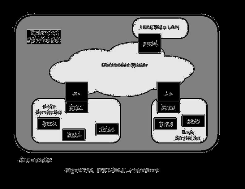
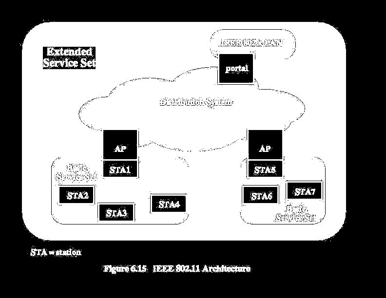
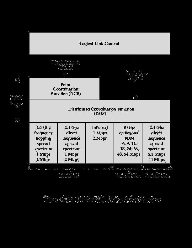
13 implemented on reliable network media, so data integrity is not sacrificed because flow control can be left to higher-layer protocols. Frame Relay implements two congestionnotification mechanisms: Forward-explicit congestion notification (FECN) Backward-explicit congestion notification (BECN) FECN and BECN each is controlled by a single bit contained in the Frame Relay frame header. The Frame Relay frame header also contains a Discard Eligibility (DE) bit, which is used to identify less important traffic that can be dropped during periods of congestion. Frame Relay versus X.25 The design of X.25 aimed to provide error-free delivery over links with high error-rates. Frame relay takes advantage of the new links with lower error-rates, enabling it to eliminate many of the services provided by X.25. The elimination of functions and fields, combined with digital links, enables frame relay to operate at speeds 20 times greater than X.25. X.25 specifies processing at layers 1, 2 and 3 of the OSI model, while frame relay operates at layers 1 and 2 only. This means that frame relay has significantly less processing to do at each node, which improves throughput by an order of magnitude. X.25 prepares and sends packets, while frame relay prepares and sends frames. X.25 packets contain several fields used for error and flow control, none of which frame relay needs. The frames in frame relay contain an expanded address field that enables frame relay nodes to direct frames to their destinations with minimal processing. X.25 has a fixed bandwidth available. It uses or wastes portions of its bandwidth as the load dictates. Frame relay can dynamically allocate bandwidth during call setup negotiation at both the physical and logical channel level. 2.Explain ATM architecture, Logical connections and its services. Asynchronous Transfer Mode (ATM) Asynchronous Transfer Mode (ATM) is an International Telecommunication Union- Telecommunications Standards Section (ITU-T) standard for cell relay wherein information for multiple service types, such as voice, video, or data, is conveyed in small, fixed-size cells. ATM networks are connection-oriented. ATM is a cell-switching and multiplexing technology that combines the benefits of circuit switching (guaranteed capacity and constant transmission delay) with those of packet switching (flexibility and efficiency for intermittent traffic). It provides scalable bandwidth from a few megabits per second (Mbps) to many gigabits per second (Gbps). Because of its asynchronous nature, ATM is more efficient than synchronous technologies, such as timedivision multiplexing (TDM). With TDM, each user is assigned to a time slot, and no other station can send in that time slot. If a station has much data to send, it can send only when its time slot comes up, even if
14 all other time slots are empty. However, if a station has nothing to transmit when its time slot comes up, the time slot is sent empty and is wasted. Because ATM is asynchronous, time slots are available on demand with information identifying the source of the transmission contained in the header of each ATM cell. ATM transfers information in fixed-size units called cells. Each cell consists of 53 octets, or bytes. The first 5 bytes contain cell-header information, and the remaining 48 contain the payload (user information). Small, fixed-length cells are well suited to transferring voice and video traffic because such traffic is intolerant of delays that result from having to wait for a large data packet to download, among other things. Figure illustrates the basic format of an ATM cell. Figure :An ATM Cell Consists of a Header and Payload Data ATM Protocol architecture: ATM is almost similar to cell relay and packets witching using X.25and framerelay.like packet switching and frame relay,atm involves the transfer of data in discrete pieces.also,like packet switching and frame relay,atm allows multiple logical connections to multiplexed over a single physical interface. in the case of ATM,the information flow on each logical connection is organised into fixed-size packets, called cells. ATM is a streamlined protocol with minimal error and flow control capabilities :this reduces the overhead of processing ATM cells and reduces the number of overhead bits required with each cell, thus enabling ATM to operate at high data rates.the use of fixed-size cells simplifies the processing required at each ATM node,again supporting the use of ATM at high data rates. The ATM architecture uses a logical model to describe the functionality that it supports. ATM functionality corresponds to the physical layer and part of the data link layer of the OSI reference model.. the protocol referencce model shown makes reference to three separate planes: user plane provides for user information transfer,along with associated controls (e.g.,flow control,error control). control plane performs call control and connection control functions. management plane includes plane management,which performs management function related to a system as a whole and provides coordination between all the planes,and layer management which performs management functions relating to resource and parameters residing in its protocol entities.

15 The ATM reference model is composed of the following ATM layers: Physical layer Analogous to the physical layer of the OSI reference model, the ATM physical layer manages the medium-dependent transmission. ATM layer Combined with the ATM adaptation layer, the ATM layer is roughly analogous to the data link layer of the OSI reference model. The ATM layer is responsible for the simultaneous sharing of virtual circuits over a physical link (cell multiplexing) and passing cells through the ATM network (cell relay). To do this, it uses the VPI and VCI information in the header of each ATM cell. ATM adaptation layer (AAL) Combined with the ATM layer, the AAL is roughly analogous to the data link layer of the OSI model. The AAL is responsible for isolating higher-layer protocols from the details of the ATM processes. The adaptation layer prepares user data for conversion into cells and segments the data into 48-byte cell payloads. Finally, the higher layers residing above the AAL accept user data, arrange it into packets, and hand it to the AAL. Figure :illustrates the ATM reference model.

16 Structure of an ATM cell An ATM cell consists of a 5 byte header and a 48 byte payload. The payload size of 48 bytes was a compromise between the needs of voice telephony and packet networks, obtained by a simple averaging of the US proposal of 64 bytes and European proposal of 32, said by some to be motivated by a European desire not to need echo-cancellers on national trunks. ATM defines two different cell formats: NNI (Network-network interface) and UNI (Usernetwork interface). Most ATM links use UNI cell format. Diagram of the UNI ATM Cell GFC VPI VPI VCI VCI VCI PT CLP HEC Diagram of the NNI ATM Cell VPI VPI VCI VCI VCI PT CLP HEC Payload (48 bytes) Payload (48 bytes) GFC = Generic Flow Control (4 bits) (default: 4-zero bits) VPI = Virtual Path Identifier (8 bits UNI) or (12 bits NNI) VCI = Virtual channel identifier (16 bits) PT = Payload Type (3 bits) CLP = Cell Loss Priority (1-bit) HEC = Header Error Correction (8-bit CRC, polynomial = X 8 + X 2 + X + 1)

17 The PT field is used to designate various special kinds of cells for Operation and Management (OAM) purposes, and to delineate packet boundaries in some AALs. Several of ATM's link protocols use the HEC field to drive a CRC-Based Framing algorithm, which allows the position of the ATM cells to be found with no overhead required beyond what is otherwise needed for header protection. The 8-bit CRC is used to correct single-bit header errors and detect multi-bit header errors. When multi-bit header errors are detected, the current and subsequent cells are dropped until a cell with no header errors is found. In a UNI cell the GFC field is reserved for a local flow control/submultiplexing system between users. This was intended to allow several terminals to share a single network connection, in the same way that two ISDN phones can share a single basic rate ISDN connection. All four GFC bits must be zero by default.the NNI cell format is almost identical to the UNI format, except that the 4-bit GFC field is re-allocated to the VPI field, extending the VPI to 12 bits. Thus, a single NNI ATM interconnection is capable of addressing almost 2 12 VPs of up to almost 2 16 VCs each (in practice some of the VP and VC numbers are reserved). A Virtual Channel (VC) denotes the transport of ATM cells which have the same unique identifier, called the Virtual Channel Identifier (VCI). This identifier is encoded in the cell header. A virtual channel represents the basic means of communication between two endpoints, and is analogous to an X.25 virtual circuit. A Virtual Path (VP) denotes the transport of ATM cells belonging to virtual channels which share a common identifier, called the Virtual Path Identifier (VPI), which is also encoded in the cell header. A virtual path, in other words, is a grouping of virtual channels which connect the same end-points. This two layer approach results in improved network performance. Once a virtual path is set up, the addition/removal of virtual channels is straightforward
18 ATM Classes of Services ATM is connection oriented and allows the user to specify the resources required on a perconnection basis (per SVC) dynamically. There are the five classes of service defined for ATM (as per ATM Forum UNI 4.0 specification). The QoS parameters for these service classes are summarized in Table 1. Service Class Quality of Service Parameter This class is used for emulating circuit switching. The cell rate is constant constant bit rate with time. CBR applications are quite sensitive to cell-delay variation. (CBR) Examples of applications that can use CBR are telephone traffic (i.e., nx64 kbps), videoconferencing, and television. variable bit rate This class allows users to send traffic at a rate that varies with time depending on the availability of user information. Statistical multiplexing non-real time is provided to make optimum use of network resources. Multimedia e- (VBR NRT) mail is an example of VBR NRT. variable bit rate This class is similar to VBR NRT but is designed for applications that are real time (VBR sensitive to cell-delay variation. Examples for real-time VBR are voice RT) with speech activity detection (SAD) and interactive compressed video. available bit rate (ABR) This class of ATM services provides rate-based flow control and is aimed at data traffic such as file transfer and . Although the standard does not require the cell transfer delay and cell-loss ratio to be guaranteed or minimized, it is desirable for switches to minimize delay and loss as much as possible. Depending upon the state of congestion in the network, the source is required to control its rate. The users are allowed to declare a minimum cell rate, which is guaranteed to the connection by the network. unspecified rate (UBR) bit This class is the catch-all, other class and is widely used today for TCP/IP. Technical Parameter Definition cell loss ratio CLR is the percentage of cells not delivered at their destination (CLR) because they were lost in the network due to congestion and buffer
19 overflow. The delay experienced by a cell between network entry and exit cell transfer points is called the CTD. It includes propagation delays, queuing delay (CTD) delays at various intermediate switches, and service times at queuing points. cell variation (CDV) delay CDV is a measure of the variance of the cell transfer delay. High variation implies larger buffering for delay-sensitive traffic such as voice and video. peak cell (PCR) rate The maximum cell rate at which the user will transmit. PCR is the inverse of the minimum cell inter-arrival time. sustained rate (SCR) cell This is the average rate, as measured over a long interval, in the order of the connection lifetime. burst (BT) This parameter determines the maximum burst that can be sent at tolerance the peak rate. This is the bucket-size parameter for the enforcement algorithm that is used to control the traffic entering the network. Benefits of ATM The benefits of ATM are the following: high performance via hardware switching dynamic bandwidth for bursty traffic class-of-service support for multimedia scalability in speed and network size common LAN/WAN architecture opportunities for simplification via VC architecture international standards compliance
20 3. Explain ATM adaptation layer in detail ATM Adaptation Layers (AAL) The use of Asynchronous Transfer Mode (ATM) technology and services creates the need for an adaptation layer in order to support information transfer protocols, which are not based on ATM. This adaptation layer defines how to segment and reassemble higher-layer packets into ATM cells, and how to handle various transmission aspects in the ATM layer. Examples of services that need adaptations are Gigabit Ethernet, IP, Frame Relay, SONET/SDH, UMTS/Wireless, etc. The main services provided by AAL (ATM Adaptation Layer) are: Segmentation and reassembly Handling of transmission errors Handling of lost and misinserted cell conditions Timing and flow control The following ATM Adaptation Layer protocols (AALs) have been defined by the ITU-T. It is meant that these AALs will meet a variety of needs. The classification is based on whether a timing relationship must be maintained between source and destination, whether the application requires a constant bit rate, and whether the transfer is connection oriented or connectionless. AAL Type 1 supports constant bit rate (CBR), synchronous, connection oriented traffic. Examples include T1 (DS1), E1, and x64 kbit/s emulation. AAL Type 2 supports time-dependent Variable Bit Rate (VBR-RT) of connectionoriented, synchronous traffic. Examples include Voice over ATM. AAL2 is also widely used in wireless applications due to the capability of multiplexing voice packets from different users on a single ATM connection. AAL Type 3/4 supports VBR, data traffic, connection-oriented, asynchronous traffic (e.g. X.25 data) or connectionless packet data (e.g. SMDS traffic) with an additional 4-byte header in the information payload of the cell. Examples include Frame Relay and X.25. AAL Type 5 is similar to AAL 3/4 with a simplified information header scheme. This AAL assumes that the data is sequential from the end user and uses the Payload Type Indicator (PTI) bit to indicate the last cell in a transmission. Examples of services that use AAL 5 are classic IP over ATM, Ethernet Over ATM, SMDS, and LAN Emulation (LANE). AAL 5 is a widely used ATM adaptation layer protocol. This protocol was intended to provide a streamlined transport facility for higher-layer protocols that are connection oriented. AAL 5 was introduced to: reduce protocol processing overhead. reduce transmission overhead. ensure adaptability to existing transport protocols.
21 T AAL1 PDU The structure of the AAL1 PDU is given in the following illustration: SN SNP CSI SC CRC EPC SAR PDU Payload 1 bit 3 3 bits 1 bit 47 bytes bits AAL1 PDU SN Sequence number. Numbers the stream of SAR PDUs of a CPCS PDU (modulo 16). The sequence number is comprised of the CSI and the SN. CSI Convergence sublayer indicator. Used for residual time stamp for clocking. SC Sequence count. The sequence number for the entire CS PDU, which is generated by the Convergence Sublayer. SNP Sequence number protection. Comprised of the CRC and the EPC. CRC Cyclic redundancy check calculated over the SAR header. EPC Even parity check calculated over the CRC. SAR PDU payload 47-byte user information field. AAL2 AAL2 provides bandwidth-efficient transmission of low-rate, short and variable packets in delay sensitive applications. It supports VBR and CBR. AAL2 also provides for variable payload within cells and across cells. AAL type 2 is subdivided into the Common Part Sublayer (CPS ) and the Service Specific Convergence Sublayer (SSCS ). AAL2 CPS Packet The CPS packet consists of a 3 octet header followed by a payload. The structure of the AAL2 CPS packet is shown in the following illustration.
22 CID LI UUI HEC Information payload 8 bits 6 bits 5 bits 5 bits 1-45/64 bytes AAL2 CPS packet CID Channelidentification. LI Length indicator. This is the length of the packet payload associated with each individual user. Value is one less than the packet payload and has a default value of 45 bytes (may be set to 64 bytes). UUI User-to-user indication. Provides a link between the CPS and an appropriate SSCS that satisfies the higher layer application HEC Header error control. AAL2 The structure of the AAL2 SAR PDU is given in the following illustration. Start field CPS-PDU payload OSF SN P AAL2 PDU payload PAD 6 bits 1 bit 1 bit 0-47 bytes AAL2 CPS PDU OSF Offset field. Identifies the location of the start of the next CPS packet within the CPS-PDU. SN Sequence number. Protects data integrity. P Parity. Protects the start field from errors. SAR PDU payload Information field of the SAR PDU.
23 PAD Padding. AAL2 SSCS Packet The SSCS conveys narrowband calls consisting of voice, voiceband data or circuit mode data. SSCS packets are transported as CPS packets over AAL2 connections. The CPS packet contains a SSCS payload. There are 3 SSCS packet types. Type 1 Unprotected; this is used by default. Type 2 Partially protected. Type 3 Fully protected: the entire payload is protected by a 10-bit CRC which is computed as for OAM cells. The remaining 2 bits of the 2-octet trailer consist of the message type field. AAL2 SSCS Type 3 Packets: The type 3 packets are used for the following: Dialled digits Channel associated signalling bits Facsimile demodulated control data Alarms User state control operations. The following illustration gives the general sturcture of AAL2 SSCS Type 3 PDUs. The format varies and each message has its own format according to the actual message type. Redundancy Time Message Message CRCstamp dependant type 10 information bits AAL2 SSCS Type 3 PDU Redundancy Packets are sent 3 times to ensure error correction. The value in this field signifies the transmission number. Time stamp Counters packet delay variation and allows a receiver to accurately reproduce the relative timing of successive events separated by a short interval.
24 Message dependant information Packet content that varies, depending on the message type. Message The message type code. type CRC-10 The 10-bit CRC. AAL3/4 AAL3/4 consists of message and streaming modes. It provides for point-to-point and pointto-multipoint (ATM layer) connections. The Convergence Sublayer (CS) of the ATM Adaptation Layer (AAL) is divided into two parts: service specific (SSCS ) and common part (CPCS ). This is illustrated in the following diagram: AAL3/4 packets are used to carry computer data, mainly SMDS traffic. AAL3/4 CPCS PDU The functions of the AAL3/4 CPCS include connectionless network layer (Class D), meaning no need for an SSCS; and frame relaying telecommunication service in Class C. The CPCS PDU is composed of the following fields: Header Info Trailer CPI Btag Basize CPCS Pad 0 Etag Length SDU bytes AAL3/4 CPCS PDU CPI Message type. Set to zero when the BAsize and Length fields are encoded in bytes. Btag Beginning tag. This is an identifier for the packet. It is repeated as the Etag. BAsize Buffer allocation size. Size (in bytes) that the receiver has to allocate to capture all the data.
25 CPCS Variable information field up to bytes. SDU PAD Padding field which is used to achieve 32-bit alignment of the length of the packet. 0 All-zero. Etag End tag. Must be the same as Btag. Length Must be the same as BASize. AAL3/4 SAR PDU The structure of the AAL3/4 SAR PDU is illustrated below: ST SN MID Information LI CRC bits 2-byte header 44 bytes 2-byte trailer 48 bytes AAL3/4 SAR PDU ST Segment type. Values may be as follows: SN Sequence number. Numbers the stream of SAR PDUs of a CPCS PDU (modulo 16). MID Multiplexing identification. This is used for multiplexing several AAL3/4 connections over one ATM link. Information This field has a fixed length of 44 bytes and contains parts of CPCS PDU. LI Length indication. Contains the length of the SAR SDU in bytes, as follows:

26 CRC Cyclic redundancy check. Functions of AAL3/4 SAR include identification of SAR SDUs; error indication and handling; SAR SDU sequence continuity; multiplexing and demultiplexing. AAL5 The type 5 adaptation layer is a simplified version of AAL3/4. It also consists of message and streaming modes, with the CS divided into the service specific and common part. AAL5 provides point-to-point and point-to-multipoint (ATM layer) connections. AAL5 is used to carry computer data such as TCP/IP. It is the most popular AAL and is sometimes referred to as SEAL (simple and easy adaptation layer). AAL5 CPCS PDU The AAL5 CPCS PDU is composed of the following fields: Info Trailer CPCS payload Pad UU CPI Length CRC bytes AAL5 CPCS PDU CPCS The actual information that is sent by the user. Note that the information comes before any length indication (as opposed to AAL3/4 where the amount of memory required is known in advance). Pad Padding bytes to make the entire packet (including control and CRC) fit into a 48-byte boundary. UU CPCS user-to-user indication to transfer one byte of user information. CPI Common part indicator is a filling byte (of value 0). This field is to be used in the future for layer management message indication. Length Length of the user information without the Pad.
27 CRC CRC-32. Used to allow identification of corrupted transmission. AAL5 SAR PDU The structure of the AAL5 CS PDU is as follows: Information PAD UU CPI Length CRC bytes AAL5 SAR PDU 8-byte trailer 4.Explain Fast Ethernet and Gigabit Ethernet in detail. Emergence of High-Speed LANs 2 Significant trends Computing power of PCs continues to grow rapidly Network computing Examples of requirements Centralized server farms Power workgroups High-speed local backbone Classical Ethernet Bus topology LAN 10 Mbps CSMA/CD medium access control protocol 2 problems: A transmission from any station can be received by all stations How to regulate transmission Solution to First Problem Data transmitted in blocks called frames: User data Frame header containing unique address of destination station CSMA/CD Carrier Sense Multiple Access/ Carrier Detection If the medium is idle, transmit. If the medium is busy, continue to listen until the channel is idle, then transmit immediately. If a collision is detected during transmission, immediately cease transmitting. After a collision, wait a random amount of time, then attempt to transmit again (repeat from step 1).


28 Medium Options at 10Mbps <data rate> <signaling method> <max length> 10Base5 10 Mbps 50-ohm coaxial cable bus Maximum segment length 500 meters 10Base-T Twisted pair, maximum length 100 meters Star topology (hub or multipoint repeater at central point) Hubs and Switches Hub Transmission from a station received by central hub and retransmitted on all outgoing lines Only one


29 transmission at a time Layer 2 Switch Incoming frame switched to one outgoing line Many transmissions at same time
30 Bridge Frame handling done in software Analyze and forward one frame at a time Store-and-forward Layer 2 Switch Frame handling done in hardware Multiple data paths and can handle multiple frames at a time Can do cut-through Layer 2 Switches Flat address space Broadcast storm Only one path between any 2 devices Solution 1: subnetworks connected by routers Solution 2: layer 3 switching, packet-forwarding logic in hardware Benefits of 10 Gbps Ethernet over ATM No expensive, bandwidth consuming conversion between Ethernet packets and ATM cells Network is Ethernet, end to end IP plus Ethernet offers QoS and traffic policing capabilities approach that of ATM Wide variety of standard optical interfaces for 10 Gbps Ethernet.


31 5. Explain Fiber channel in detail. Fibre Channel 2 methods of communication with processor: I/O channel Network communications Fibre channel combines both Simplicity and speed of channel communications Flexibility and interconnectivity of network communications
32 I/O channel Hardware based, high-speed, short distance Direct point-to-point or multipoint communications linkdata type qualifiers for routing payload Link-level constructs for individual I/O operationsprotocol specific specifications to support e.g. SCSI Fibre Channel Network-Oriented Facilities Full multiplexing between multiple destinations Peer-to-peer connectivity between any pair of ports Internetworking with other connection technologies Fibre Channel Requirements Full duplex links with 2 fibres/link 100 Mbps 800 Mbps Distances up to 10 km Small connectors high-capacity Greater connectivity than existing multidrop channels Broad availability Support for multiple cost/performance levels Support for multiple existing interface command sets Fibre Channel Protocol Architecture FC-0 Physical Media FC-1 Transmission Protocol FC-2 Framing Protocol FC-3 Common Services FC-4 Mapping. 6.Explain IEEE WLAN in detail. Wireless LAN Requirements Throughput Number of nodes Connection to backbone Service area Battery power consumption Transmission robustness and security Collocated network operation License-free operation Handoff/roaming Dynamic configuration IEEE Services Association Reassociation Disassociation Authentication Privacy
33
34
ATM Logical Connections: VCC. ATM Logical Connections: VPC
 ATM Logical Connections: VCC Logical Connections in ATM are referred to as virtual channel connections (VCCs). Virtual channel (VC) is a generic term used to describe unidirectional transport of ATM cells
ATM. Asynchronous Transfer Mode. (and some SDH) (Synchronous Digital Hierarchy)
 (Synchronous Digital Hierarchy)") ATM Asynchronous Transfer Mode (and some SDH) (Synchronous Digital Hierarchy) Why use ATM? Circuit switched connections: After initial setup no processing in network nodes Fixed bit rates, fixed time delay
ATM Asynchronous Transfer Mode (and some SDH) (Synchronous Digital Hierarchy) Why use ATM? Circuit switched connections: After initial setup no processing in network nodes Fixed bit rates, fixed time delay
ATM Technology in Detail. Objectives. Presentation Outline
 ATM Technology in Detail Professor Richard Harris Objectives You should be able to: Discuss the ATM protocol stack Identify the different layers and their purpose Explain the ATM Adaptation Layer Discuss
! Cell streams relating to different media types are multiplexed together on a statistical basis for transmission and switching.
 Asynchronous Transfer Mode (ATM) Networks! All source media is first broken down into a stream of fixed sized units known as cells.! Cell streams relating to different media types are multiplexed together
Asynchronous Transfer Mode
 ATM Asynchronous Transfer Mode CS420/520 Axel Krings Page 1 Protocol Architecture (diag) CS420/520 Axel Krings Page 2 1 Reference Model Planes User plane Provides for user information transfer Control
Protocol Architecture (diag) Computer Networks. ATM Connection Relationships. ATM Logical Connections
 Computer Networks. ATM Connection Relationships. ATM Logical Connections") 168 430 Computer Networks Chapter 11 Asynchronous Transfer Mode Protocol Architecture Similarities between ATM and packet switching Transfer of data in discrete chunks Multiple logical connections over
168 430 Computer Networks Chapter 11 Asynchronous Transfer Mode Protocol Architecture Similarities between ATM and packet switching Transfer of data in discrete chunks Multiple logical connections over
William Stallings Data and Computer Communications 7 th Edition. Chapter 11 Asynchronous Transfer Mode
 William Stallings Data and Computer Communications 7 th Edition Chapter 11 Asynchronous Transfer Mode Protocol Architecture Similarities between ATM and packet switching Transfer of data in discrete chunks
Asynchronous. nous Transfer Mode. Networks: ATM 1
 Asynchronous nous Transfer Mode (ATM) Networks: ATM 1 Issues Driving LAN Changes Traffic Integration Voice, video and data traffic Multimedia became the buzz word One-way batch Two-way batch One-way interactive
Introduction. High Speed LANs. Emergence of High-Speed LANs. Characteristics of High Speed LANS. Text ch. 6, High-Speed Networks and
 High Speed LANs 3BA33 David Lewis 2 nd Semester 2006-07 3BA33 D.Lewis 2007 1 Characteristics of High Speed LANS 3BA33 D.Lewis 2007 3 Introduction Fast Ethernet and Gigabit Ethernet Fibre Channel High-speed
Communication Networks
 Communication Networks Chapter 3 Multiplexing Frequency Division Multiplexing (FDM) Useful bandwidth of medium exceeds required bandwidth of channel Each signal is modulated to a different carrier frequency
ATM. Asynchronous Transfer Mode. these slides are based on USP ATM slides from Tereza Carvalho. ATM Networks Outline
 ATM Asynchronous Transfer Mode these slides are based on USP ATM slides from Tereza Carvalho 1 ATM Networks Outline ATM technology designed as a support for ISDN Definitions: STM and ATM Standardization
This Lecture. BUS Computer Facilities Network Management X.25. X.25 Packet Switch. Wide Area Network (WAN) Technologies. X.
 Technologies. X.") This ecture BUS350 - Computer Facilities Network Management Wide rea Network (WN) Technologies. X.5 Frame Relay TM Faculty of Information Technology Monash University Faculty of Information Technology
This ecture BUS350 - Computer Facilities Network Management Wide rea Network (WN) Technologies. X.5 Frame Relay TM Faculty of Information Technology Monash University Faculty of Information Technology
CPEG 514. Lecture 11 Asynchronous Transfer Mode (ATM) CPEG 514
 CPEG 514") Lecture 11 Asynchronous Transfer Mode () Outline Introduction Virtual Circuit Setup PVC vs. SVC Quality of Service and Congestion Control IP over and Frame Relay interworking Network (integrated voice,
Lecture 11 Asynchronous Transfer Mode () Outline Introduction Virtual Circuit Setup PVC vs. SVC Quality of Service and Congestion Control IP over and Frame Relay interworking Network (integrated voice,
Part 5: Link Layer Technologies. CSE 3461: Introduction to Computer Networking Reading: Chapter 5, Kurose and Ross
 Part 5: Link Layer Technologies CSE 3461: Introduction to Computer Networking Reading: Chapter 5, Kurose and Ross 1 Outline PPP ATM X.25 Frame Relay 2 Point to Point Data Link Control One sender, one receiver,
Bandwidth-on-Demand up to very high speeds. Variety of physical layers using optical fibre, copper, wireless. 3BA33 D.Lewis
 Broadband ISDN 3BA33 David Lewis 3BA33 D.Lewis 2007 1 B-ISDN Model has 3 planes User Control Management 3BA33 D.Lewis 2007 3 Broadband ISDN Was Expected to be the Universal Network of the future Takes
Wireless Networks. Communication Networks
 Wireless Networks Communication Networks Types of Communication Networks Traditional Traditional local area network (LAN) Traditional wide area network (WAN) Higher-speed High-speed local area network
Asynchronous Transfer Mode (ATM) ATM concepts
 ATM concepts") Asynchronous Transfer Mode (ATM) Asynchronous Transfer Mode (ATM) is a switching technique for telecommunication networks. It uses asynchronous time-division multiplexing,[1][2] and it encodes data into
Asynchronous Transfer Mode (ATM) Asynchronous Transfer Mode (ATM) is a switching technique for telecommunication networks. It uses asynchronous time-division multiplexing,[1][2] and it encodes data into
Master Course Computer Networks IN2097
 Chair for Network Architectures and Services Prof. Carle Department of Computer Science TU München Master Course Computer Networks IN2097 Prof. Dr.-Ing. Georg Carle Christian Grothoff, Ph.D. Stephan Günther
Introduction to ATM Traffic Management on the Cisco 7200 Series Routers
 CHAPTER 1 Introduction to ATM Traffic Management on the Cisco 7200 Series Routers In the latest generation of IP networks, with the growing implementation of Voice over IP (VoIP) and multimedia applications,
Ethernet Switches (more)
") Ethernet Switches layer 2 (frame) forwarding, filtering using LAN addresses Switching: A-to-B and A - to-b simultaneously, no collisions large number of interfaces often: individual hosts, star-connected
Ethernet Switches layer 2 (frame) forwarding, filtering using LAN addresses Switching: A-to-B and A - to-b simultaneously, no collisions large number of interfaces often: individual hosts, star-connected
1997, Scott F. Midkiff 1
 Welcome to! Loooooooooooooooots of acronyms! By Scott Midkiff ECpE/CS 5516, VPI Spring 1997 (modified by Marc Abrams for Spring 1998) A lot of what s in came from the phone and ing worlds, not the LAN
BROADBAND AND HIGH SPEED NETWORKS
 BROADBAND AND HIGH SPEED NETWORKS INTRODUCTION ATM stands for Asynchronous Transfer Mode ATM is a flexible high bandwidth, low delay network technology that is: Capable of handling voice, video and data
Chapter 10. Circuits Switching and Packet Switching 10-1
 Chapter 10 Circuits Switching and Packet Switching 10-1 Content Switched communication networks Circuit switching networks Circuit-switching concepts Packet-switching principles X.25 (mentioned but not
Lesson 3 Network technologies - Controlling
 Lesson 3 Network technologies - Controlling Objectives : Network control or traffic engineering is one of the important techniques in the network. Understanding QoS control, traffic engineering and OAM
ATM Introduction. The Grand Unification 2005/03/11. (C) Herbert Haas
 Herbert Haas") ATM Introduction The Grand Unification Agenda What is it? Who wants it? Who did it? Header and Switching ATM Layer Hypercube Adaptation Layers Signaling Addresses 2 What is ATM? High-Speed Virtual Circuits
ATM Introduction The Grand Unification Agenda What is it? Who wants it? Who did it? Header and Switching ATM Layer Hypercube Adaptation Layers Signaling Addresses 2 What is ATM? High-Speed Virtual Circuits
Switched Multimegabit Data Service (SMDS)
") CHAPTER 14 Switched Multimegabit Data Service (SMDS) Background Switched Multimegabit Data Service (SMDS) is a high-speed, packet-switched, datagram-based WAN networking technology used for communication
CHAPTER 14 Switched Multimegabit Data Service (SMDS) Background Switched Multimegabit Data Service (SMDS) is a high-speed, packet-switched, datagram-based WAN networking technology used for communication
Basic concept of ATM communication
 Lesson 3 AM Network (2days) Basic concept of AM communication Protocol structure of AM network Hardware routing OSI reference model AM network protocols Objectives : AM concepts are typical connection
ATM networks. C. Pham Université de Pau et des Pays de l Adour LIUPPA Laboratory
 ATM networks C. Pham Université de Pau et des Pays de l Adour LIUPPA Laboratory http://www.univ-pau.fr/~cpham Congduc.Pham@univ-pau.fr Issues Driving LAN Changes Traffic Integration Voice, video and data
Packet Switching. Hongwei Zhang Nature seems to reach her ends by long circuitous routes.
 Problem: not all networks are directly connected Limitations of directly connected networks: limit on the number of hosts supportable limit on the geographic span of the network Packet Switching Hongwei
BROADBAND AND HIGH SPEED NETWORKS
 BROADBAND AND HIGH SEED NETWORKS LAYERS The function and associated information of the planes is as follows: The reference model is composed of the following planes: Control lane manages the call and connection.
Cell Switching (ATM) Commonly transmitted over SONET other physical layers possible. Variable vs Fixed-Length Packets
 Commonly transmitted over SONET other physical layers possible. Variable vs Fixed-Length Packets") Cell Switching (ATM) Connection-oriented packet-switched network Used in both WAN and LAN settings Signaling (connection setup) Protocol: Q2931 Specified by ATM forum Packets are called cells 5-byte header
Cell Switching (ATM) Connection-oriented packet-switched network Used in both WAN and LAN settings Signaling (connection setup) Protocol: Q2931 Specified by ATM forum Packets are called cells 5-byte header
different problems from other networks ITU-T specified restricted initial set Limited number of overhead bits ATM forum Traffic Management
 Traffic and Congestion Management in ATM 3BA33 David Lewis 3BA33 D.Lewis 2007 1 Traffic Control Objectives Optimise usage of network resources Network is a shared resource Over-utilisation -> congestion
ATM Quality of Service (QoS)
") ATM Quality of Service (QoS) Traffic/Service Classes, Call Admission Control Usage Parameter Control, ABR Agenda Introduction Service Classes and Traffic Attributes Traffic Control Flow Control Special
ATM Quality of Service (QoS) Traffic/Service Classes, Call Admission Control Usage Parameter Control, ABR Agenda Introduction Service Classes and Traffic Attributes Traffic Control Flow Control Special
DigiPoints Volume 1. Leader Guide. Module 12 Asynchronous Transfer Mode. Summary. Outcomes. Objectives. Prerequisites
 Asynchronous Transfer Mode Page 12.i DigiPoints Volume 1 Module 12 Asynchronous Transfer Mode Summary This last module of, covers ATM, and provides an end-to-end data communications model that draws on
Switched Multimegabit Data Service
 CHAPTER 14 Chapter Goals Tell how SMDS works, and describe its components. Describe the operational elements of the SMDS environment, and outline its underlying protocol. Discuss related technologies.
Frame Relay. Frame Relay Information 1 of 18
 Frame Relay Information 1 of 18 This document was retrieved from the Web and has been been edited by Thomas Jerry Scott for use in his TCP/IP network classes. Chapter Goals Describe the history of Frame
Asynchronous Transfer Mode (ATM) Broadband ISDN (B-ISDN)
 Broadband ISDN (B-ISDN)") Asynchronous Transfer Mode (ATM) Broadband ISDN (B-ISDN) Petr Grygárek rek 1 ATM basic characteristics Integrates transfer of voice, video, data and other media using statistical al multiplexing ing multiplexes
Asynchronous Transfer Mode (ATM) Broadband ISDN (B-ISDN) Petr Grygárek rek 1 ATM basic characteristics Integrates transfer of voice, video, data and other media using statistical al multiplexing ing multiplexes
ST.MOTHER THERESA ENGINEERING COLLEGE
 ST.MOTHER CHETTINAD COLLEGE OF ENGINEERING THERESA & TECHNOLOGY ENGINEERING COLLEGE DEPARTMENT OF ELECTRONICS AND COMMUNICATION ENGINEERING SUBJECT CODE: CS 2060 SEM/YEAR: VII/IV SUBJECT NAME: HIGH SPEED
M242 COMPUTER NETWORS AND SECURITY
 M242 COMPUTER NETWORS AND SECURITY 2.1. Network Models: UNIT - II OSI MODEL AND LAN PROTOCOLS 1. Explain Network model A network is a combination of hardware and software that sends data from one location
Ch. 4 - WAN, Wide Area Networks
 1 X.25 - access 2 X.25 - connection 3 X.25 - packet format 4 X.25 - pros and cons 5 Frame Relay 6 Frame Relay - access 7 Frame Relay - frame format 8 Frame Relay - addressing 9 Frame Relay - access rate
A T M. Cell Switched Technology. not SMDS. Defacto Standard Multimedia capable Use with SONET or SDH. Fixed Length - 53 bytes. DigiPoints Volume 1
 A T M Cell Switched Technology Fixed Length - 53 bytes not SMDS Defacto Standard Multimedia capable Use with SONET or SDH SCTE VA 12.1 SONET Optical Carrier (OC) Rates and SDH Synchronous Transport Module
Introduction. ATM Technology. What is ATM? Agenda
 Introduction Technology Asynchronous Transfer Mode Principles, ing, AAL, Signaling In 1986 the CCITT (now ITU-T) adopted as background technology for B-ISDN B-ISDN intended to replace several widespread
EC1009 HIGH SPEED NETWORKS (ELECTIVE) (2 marks Questions and answers)
 (2 marks Questions and answers)") DEPARTMENT OF ECE EC1009 HIGH SPEED NETWORKS (ELECTIVE) (2 marks Questions and answers) FINAL YEAR 7 th SEMESTER UNIT I HIGH SPEED NETWORKS 1) What is common channel signaling? The data s and control signals
DEPARTMENT OF ECE EC1009 HIGH SPEED NETWORKS (ELECTIVE) (2 marks Questions and answers) FINAL YEAR 7 th SEMESTER UNIT I HIGH SPEED NETWORKS 1) What is common channel signaling? The data s and control signals
Intermediate Traffic Management
 Intermediate Traffic Management This presentation has been generated by the ATM Forum for the purpose of educating the public on ATM Technology and the ATM Forum s activities. This presentation is the
Appendix 5 - ATM Technology in Detail
 Technology Asynchronous Transfer Mode Principles, Layering, AAL, Signaling Agenda Introduction Reference Model Physical Layer Layer Switching Details Adaptation Layer Signaling and Addressing Technology,
Lecture 03 Chapter 11 Asynchronous Transfer Mode
 NET 456 High Speed Networks Lecture 03 Chapter 11 Asynchronous Transfer Mode Dr. Anis Koubaa Reformatted slides from textbook Data and Computer Communications, Ninth Edition by William Stallings, 1 (c)
HWP2 Application level query routing HWP1 Each peer knows about every other beacon B1 B3
 HWP2 Application level query routing HWP1 Each peer knows about every other beacon B2 B1 B3 B4 B5 B6 11-Feb-02 Computer Networks 1 HWP2 Query routing searchget(searchkey, hopcount) Rget(host, port, key)
ATM Asynchronous Transfer Mode revisited
 ATM Asynchronous Transfer Mode revisited ACN 2007 1 ATM GOAL To establish connections between an arbitrary number of hosts...... over channels that fulfills a certain QoS level. -> ATM networks make it
Hubs. Interconnecting LANs. Q: Why not just one big LAN?
 Interconnecting LANs Q: Why not just one big LAN? Limited amount of supportable traffic: on single LAN, all stations must share bandwidth limited length: 802.3 specifies maximum cable length large collision
Advanced Internet Technologies
 Advanced Internet Technologies Chapter 2 ATM Dr.-Ing. Falko Dressler Chair for Computer Networks & Internet Wilhelm-Schickard-Institute for Computer Science University of Tübingen http://net.informatik.uni-tuebingen.de/
Module 3. Wide Area Networking (WAN)
") Module 3 Wide Area Networking (WAN) When many nodes or LAN s are connected together in a large scale, we have a WAN. This may be world wide. Because of the separation of the nodes, the Public Data Network
Module 3 Wide Area Networking (WAN) When many nodes or LAN s are connected together in a large scale, we have a WAN. This may be world wide. Because of the separation of the nodes, the Public Data Network
Packet Switching - Asynchronous Transfer Mode. Introduction. Areas for Discussion. 3.3 Cell Switching (ATM) ATM - Introduction
 ATM - Introduction") Areas for Discussion Packet Switching - Asynchronous Transfer Mode 3.3 Cell Switching (ATM) Introduction Cells Joseph Spring School of Computer Science BSc - Computer Network Protocols & Arch s Based on
Areas for Discussion Packet Switching - Asynchronous Transfer Mode 3.3 Cell Switching (ATM) Introduction Cells Joseph Spring School of Computer Science BSc - Computer Network Protocols & Arch s Based on
BROADBAND AND HIGH SPEED NETWORKS
 BROADBAND AND HIGH SPEED NETWORKS ATM SERVICE CATEGORIES Service Categories : represent particular combinations of traffic parameters and QoS parameters. These parameters are determined by users for a
PRACTICES FNC Guide to ATM GUIDE TO ATM CROSS PRODUCT DOCUMENTATION ISSUE 1, JANUARY 2002 FUJITSU NETWORK COMMUNICATIONS, INC.
 PRACTICES GUIDE TO ATM CROSS PRODUCT DOCUMENTATION ISSUE 1, JANUARY 2002 FUJITSU NETWORK COMMUNICATIONS, INC. Copyrights, Trademarks, and Disclaimers All products or services mentioned in this document
Figure 10.1 Cell switching principles: (a) routing schematic; (b) VP routing; (c) VC routing.
 routing schematic; (b) VP routing; (c) VC routing.") Figure. Cell switching principles: (a) routing schematic; (b) VP routing; (c) VC routing. (a) PCI =,,, 4 4 PCI =, 4 4 6 PCI = 6, Link/Port RT Link/Port RT Link/Port RT In Port PCI 4 Out Port PCI 4 6 Port
Figure. Cell switching principles: (a) routing schematic; (b) VP routing; (c) VC routing. (a) PCI =,,, 4 4 PCI =, 4 4 6 PCI = 6, Link/Port RT Link/Port RT Link/Port RT In Port PCI 4 Out Port PCI 4 6 Port
WAN Technologies (to interconnect IP routers) Mario Baldi
 Mario Baldi") WAN Technologies (to interconnect IP routers) Mario Baldi www.baldi.info WAN_Technologies - 1 Copyright: see page 2 Copyright Notice This set of transparencies, hereinafter referred to as slides, is protected
WAN Technologies (to interconnect IP routers) Mario Baldi www.baldi.info WAN_Technologies - 1 Copyright: see page 2 Copyright Notice This set of transparencies, hereinafter referred to as slides, is protected
Internetworking Part 1
 CMPE 344 Computer Networks Spring 2012 Internetworking Part 1 Reading: Peterson and Davie, 3.1 22/03/2012 1 Not all networks are directly connected Limit to how many hosts can be attached Point-to-point:
WAN technology which are to be discussed:
 WAN Technology Operates at 3 layer OSI model as below: 1. PHY 2. Data Link 3. Network Most of WAN technology are packetswitched network categorized as Switched Virtual circuit Network ( 3-phase, connection
Lecture 4 Wide Area Networks - Asynchronous Transfer Mode
 DATA AND COMPUTER COMMUNICATIONS Lecture 4 Wide Area Networks - Asynchronous Transfer Mode Mei Yang Based on Lecture slides by William Stallings 1 ATM a streamlined packet transfer interface similarities
MPLS AToM Overview. Documentation Specifics. Feature Overview
 MPLS AToM Overview This document provides an introduction to MPLS AToM and includes the following sections: Documentation Specifics, page 14 Feature Overview, page 14 Benefits, page 26 What To Do Next,
Asynchronous Transfer Mode
 CHAPTER 20 This chapter describes the level of support that Cisco ANA provides for ATM, as follows: Technology Description, page 20-1 Information Model Objects (IMOs), page 20-3 Vendor-Specific Inventory
CISC452 Telecommunications Systems. Lesson 6 Frame Relay and ATM
 CISC452 Telecommunications Systems Lesson 6 Frame Relay and ATM 1 Technology Comparison Private Line X.25 SMDS Frame Relay ATM IP Speed 56K - 622M 9.6K - 2.048M 56K - 34M Dial - 45M 1.5M - 622M Dial -
11. Traffic management in ATM. lect11.ppt S Introduction to Teletraffic Theory Spring 2003
 lect11.ppt S-38.145 - Introduction to Teletraffic Theory Spring 2003 1 Contents Introduction ATM technique Service categories and traffic contract Traffic and congestion control in ATM Connection Admission
CHAPTER -1. Introduction to Computer Networks
 CHAPTER -1 Introduction to Computer Networks PRELIMINARY DEFINITIONS computer network :: [Tanenbaum] a collection of autonomous computers interconnected by a single technology. communications network ::a
ATM Networks. Raj Jain
 ATM Networks Professor of Computer and Information Sciences The Ohio State University Columbus, OH 43210-1277 http://www.cis.ohio-state.edu/~jain/ 1 Overview ATM: Overview ATM Protocol Layers Network Interfaces
Local Area Network Overview
 Local Area Network Overview Chapter 15 CS420/520 Axel Krings Page 1 LAN Applications (1) Personal computer LANs Low cost Limited data rate Back end networks Interconnecting large systems (mainframes and
CCNA Exploration1 Chapter 7: OSI Data Link Layer
 CCNA Exploration1 Chapter 7: OSI Data Link Layer LOCAL CISCO ACADEMY ELSYS TU INSTRUCTOR: STELA STEFANOVA 1 Explain the role of Data Link layer protocols in data transmission; Objectives Describe how the
Module 10 Frame Relay and ATM
 Module 10 Frame Relay and ATM Lesson 35 ATM: Virtual Path, Virtual Channel. ATM Adaptation Layer (AAL) 10.3.1 VIRTUAL PATH AND VIRTUAL CHANNEL Connection between two endpoints is accomplished through virtual
06/02/ Metropolitan Area Networks. Local & Metropolitan Area Networks. 0. Overview. 1. Internetworking ACOE322. Lecture 4
 1 Local & Metropolitan Area Networks ACOE322 Lecture 4 Metropolitan Area Networks Dr. L. Christofi 1 0. Overview In this section the following topics will be covered: 1. Internetworking devices 2. Wide
Module 10 Frame Relay and ATM
 Module 10 Frame Relay and ATM Lesson 34 ATM: Concepts And Header 10.2.1 INTRODUCTION IP has a varying packet size which causes no problem while multiplexing but makes switching difficult. ATM uses a fixed
BROADBAND AND HIGH SPEED NETWORKS
 BROADBAND AND HIGH SPEED NETWORKS ATM SWITCHING ATM is a connection-oriented transport concept An end-to-end connection (virtual channel) established prior to transfer of cells Signaling used for connection
Computer Facilities and Network Management BUS3150 Tutorial - Week 13
 Computer Facilities and Network Management BUS3150 Tutorial - Week 13 *** FOR TUTORS ONLY *** The answers provided here are only brief guides. If you have any comments or suggestions for improvement to
Rohit Goyal 1, Raj Jain 1, Sonia Fahmy 1, Shobana Narayanaswamy 2
 MODELING TRAFFIC MANAGEMENT IN ATM NETWORKS WITH OPNET Rohit Goyal 1, Raj Jain 1, Sonia Fahmy 1, Shobana Narayanaswamy 2 1. The Ohio State University, Department of Computer and Information Science, 2015
Bridging and Switching Basics
 CHAPTER 4 Bridging and Switching Basics This chapter introduces the technologies employed in devices loosely referred to as bridges and switches. Topics summarized here include general link-layer device
NETWORK PARADIGMS. Bandwidth (Mbps) ATM LANS Gigabit Ethernet ATM. Voice, Image, Video, Data. Fast Ethernet FDDI SMDS (DQDB)
 ATM LANS Gigabit Ethernet ATM. Voice, Image, Video, Data. Fast Ethernet FDDI SMDS (DQDB)") 1. INTRODUCTION NETWORK PARADIGMS Bandwidth (Mbps) 1000 ATM LANS Gigabit Ethernet ATM 100 10 Fast Ethernet FDDI SMDS (DQDB) Voice, Image, Video, Data 1 Ethernet/ Token Ring/ Token Bus Frame Relay X.25
1. INTRODUCTION NETWORK PARADIGMS Bandwidth (Mbps) 1000 ATM LANS Gigabit Ethernet ATM 100 10 Fast Ethernet FDDI SMDS (DQDB) Voice, Image, Video, Data 1 Ethernet/ Token Ring/ Token Bus Frame Relay X.25
11. Traffic management in ATM
 lect11.ppt S-38.145 - Introduction to Teletraffic Theory - Fall 2000 1 Contents Introduction ATM technique Service categories Traffic contract Traffic and congestion control in ATM Connection Admission
ITU-T I.150. B-ISDN asynchronous transfer mode functional characteristics
 INTERNATIONAL TELECOMMUNICATION UNION ITU-T I.150 TELECOMMUNICATION STANDARDIZATION SECTOR OF ITU (02/99) SERIES I: INTEGRATED SERVICES DIGITAL NETWORK General structure General description of asynchronous
INTERNATIONAL TELECOMMUNICATION UNION INTEGRATED SERVICES DIGITAL NETWORK (ISDN) OVERALL NETWORK ASPECTS AND FUNCTIONS
 OVERALL NETWORK ASPECTS AND FUNCTIONS") INTERNATIONAL TELECOMMUNICATION UNION ITU-T I.363 TELECOMMUNICATION (03/93) STANDARDIZATION SECTOR OF ITU INTEGRATED SERVICES DIGITAL NETWORK (ISDN) OVERALL NETWORK ASPECTS AND FUNCTIONS B-ISDN ATM ADAPTATION
INTERNATIONAL TELECOMMUNICATION UNION ITU-T I.363 TELECOMMUNICATION (03/93) STANDARDIZATION SECTOR OF ITU INTEGRATED SERVICES DIGITAL NETWORK (ISDN) OVERALL NETWORK ASPECTS AND FUNCTIONS B-ISDN ATM ADAPTATION
Congestion in Data Networks. Congestion in Data Networks
 Congestion in Data Networks CS420/520 Axel Krings 1 Congestion in Data Networks What is Congestion? Congestion occurs when the number of packets being transmitted through the network approaches the packet
Rohit Goyal 1, Raj Jain 1, Sonia Fahmy 1, Shobana Narayanaswamy 2
 MODELING TRAFFIC MANAGEMENT IN ATM NETWORKS WITH OPNET Rohit Goyal 1, Raj Jain 1, Sonia Fahmy 1, Shobana Narayanaswamy 2 1. The Ohio State University, Department of Computer and Information Science, 2015
Understanding the Variable Bit Rate Real Time (VBR rt) Service Category for ATM VCs
 Service Category for ATM VCs") Understanding the Variable Bit Rate Real Time (VBR rt) Service Category for ATM VCs Document ID: 10414 Contents Introduction Prerequisites Requirements Components Used Conventions What is Variable Bit
Understanding the Variable Bit Rate Real Time (VBR rt) Service Category for ATM VCs Document ID: 10414 Contents Introduction Prerequisites Requirements Components Used Conventions What is Variable Bit
ATM Networks: An Overview
 ATM Networks: An Overview Professor of Computer and Information Sciences Columbus, OH 43210-1277 http://www.cis.ohio-state.edu/~jain/ 2-1 MBone Instructions Handouts for the class are available on-line:
Network management and QoS provisioning - revise. When someone have to share the same resources is possible to consider two particular problems:
 Revise notes Multiplexing & Multiple Access When someone have to share the same resources is possible to consider two particular problems:. multiplexing;. multiple access. The first one is a centralized
Lecture (04 & 05) Packet switching & Frame Relay techniques Dr. Ahmed ElShafee
 Packet switching & Frame Relay techniques Dr. Ahmed ElShafee") Agenda Lecture (04 & 05) Packet switching & Frame Relay techniques Dr. Ahmed ElShafee Packet switching technique Packet switching protocol layers (X.25) Frame Relay ١ Dr. Ahmed ElShafee, ACU Fall 2011,
Agenda Lecture (04 & 05) Packet switching & Frame Relay techniques Dr. Ahmed ElShafee Packet switching technique Packet switching protocol layers (X.25) Frame Relay ١ Dr. Ahmed ElShafee, ACU Fall 2011,
Lecture (04 & 05) Packet switching & Frame Relay techniques
 Packet switching & Frame Relay techniques") Lecture (04 & 05) Packet switching & Frame Relay techniques Dr. Ahmed ElShafee ١ Dr. Ahmed ElShafee, ACU Fall 2011, Networks I Agenda Packet switching technique Packet switching protocol layers (X.25)
Lecture (04 & 05) Packet switching & Frame Relay techniques Dr. Ahmed ElShafee ١ Dr. Ahmed ElShafee, ACU Fall 2011, Networks I Agenda Packet switching technique Packet switching protocol layers (X.25)
What Is Congestion? Computer Networks. Ideal Network Utilization. Interaction of Queues
 168 430 Computer Networks Chapter 13 Congestion in Data Networks What Is Congestion? Congestion occurs when the number of packets being transmitted through the network approaches the packet handling capacity
Metropolitan Area Networks
 Metropolitan Area Networks Bridge larger distances than a LAN, usage e.g. within the city range or on a campus Only one or two cables, no switching elements. Thus a simple network design is achieved All
Vanguard Managed Solutions
 Vanguard Managed Solutions Vanguard Applications Ware IP and LAN Feature Protocols Asynchronous Transfer Mode Notice 2005 Vanguard Managed Solutions, LLC 575 West Street Mansfield, Massachusetts 02048
Communication Networks
 Communication Networks Chapter 7 Connection Oriented Packet Data Networks Communication Networks - 7. Connection Oriented PDNs 236 Overview 1. Fundamentals of Connection-Oriented Packet Switching 2. X.25
ET4254 Communications and Networking 1
 Topic 10:- Local Area Network Overview Aims:- LAN topologies and media LAN protocol architecture bridges, hubs, layer 2 & 3 switches 1 LAN Applications (1) personal computer LANs low cost limited data
Network Working Group Request for Comments: 2761 Category: Informational February 2000
 Network Working Group Request for Comments: 2761 Category: Informational J. Dunn C. Martin ANC, Inc. February 2000 Terminology for ATM Benchmarking Status of this Memo This memo provides information for
NAME: (Exam :SECTION A) Notes: Any script without a name will receive no points. You must show the calculations for the descriptive questions.
 Notes: Any script without a name will receive no points. You must show the calculations for the descriptive questions.") SAMPLE TEST from past EXAMS Exam3 Chapters: 14, 19, 21, 23, 24. Type of questions: multiple choices, Fill in the gaps, short answer questions YOU MUST BRING SCANTRON sheets for the multiple choices (4.5
SAMPLE TEST from past EXAMS Exam3 Chapters: 14, 19, 21, 23, 24. Type of questions: multiple choices, Fill in the gaps, short answer questions YOU MUST BRING SCANTRON sheets for the multiple choices (4.5
Voice And Telephony over ATM: Status
 Voice And Telephony over ATM: Status Columbus, OH 43210 Jain@CIS.Ohio-State.Edu http://www.cis.ohio-state.edu/~jain/ March 1998 1 Overview VTOA: Protocol Stack and Services AAL: AAL1, AAL5, New AAL2 Interworking
Packet Switching Techniques
 Packet Switching Techniques 188lecture3.ppt Pasi Lassila 1 Problem Aim: Build larger networks connecting more users also spanning different network technologies Shared media networks limited number of
Asynchronous_Transfer_Mode_Switching
 Asynchronous Transfer Mode (ATM) is an International Telecommunication Union-Telecommunications Standards Section (ITU-T) standard for cell relay wherein information for multiple service types, such as
Common Protocols. The grand finale. Telephone network protocols. Traditional digital transmission
 The grand finale Common Protocols An Engineering Approach to Computer Networking Previous chapters presented principles, but not protocol details these change with time real protocols draw many things
CH : 15 LOCAL AREA NETWORK OVERVIEW
 CH : 15 LOCAL AREA NETWORK OVERVIEW P. 447 LAN (Local Area Network) A LAN consists of a shared transmission medium and a set of hardware and software for interfacing devices to the medium and regulating
Administrivia. Homework on class webpage If you are having problems following me in class (or doing the homework problems), please buy the textbook
, please buy the textbook") Administrivia Homework on class webpage If you are having problems following me in class (or doing the homework problems), please buy the textbook Project Discussion class_ gotcha Reading finally on webpage
Administrivia Homework on class webpage If you are having problems following me in class (or doing the homework problems), please buy the textbook Project Discussion class_ gotcha Reading finally on webpage
Chapter 15 Computer and Multimedia Networks
 Chapter 15 Computer and Multimedia Networks 15.1 Basics of Computer and Multimedia Networks 15.2 Multiplexing Technologies 15.3 LAN and WAN 15.4 Access Networks 15.5 Common Peripheral Interfaces 15.6 Further
CN-100 Network Analyzer Product Overview
 CN-100 Network Analyzer Product Overview CN-100 network analyzers offer an extremely powerful yet cost effective solution for today s complex networking requirements. Test Ethernet or ATM networks with