Применение MPLS в сетях связи. (Часть 2)
|
|
|
- Phebe Flowers
- 5 years ago
- Views:
Transcription
 Дополнительные главы")

1 Применение MPLS в сетях связи. (Часть 2) Дополнительные главы Компьютерных сетей и телекоммуникаций. Васин В.В. CCIE, ECE, CCSI
2 MPLS VPN Technology Introducing VPNs

3 Traditional Router-Based Networks Traditional router-based networks connect customer sites through routers connected via dedicated point-to-point links.

4 Virtual Private Networks VPNs replace dedicated point-to-point links with emulated point-to-point links sharing common infrastructure. Customers use VPNs primarily to reduce their operational costs.
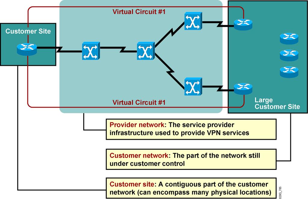
5 VPN Terminology

6 VPN Terminology (Cont.)
7 VPN Implementation Models VPN services can be offered based on two major models: Overlay VPNs, in which the service provider provides virtual point-to-point links between customer sites Peer-to-peer VPNs, in which the service provider participates in the customer routing

8 Overlay VPNs: Hub-and-Spoke Topology

9 Overlay VPNs: Redundant Hub-and-Spoke Topology

10 Overlay VPNs: Layer 2 Implementation This is the traditional switched WAN solution: The service provider establishes Layer 2 virtual circuits between customer sites. The customer is responsible for all higher layers.

11 Overlay VPNs: IP Tunneling VPN is implemented with IP-over-IP tunnels: Tunnels are established with GRE or IPsec. GRE is simpler (and quicker); IPsec provides authentication and security.
.")
12 Overlay VPNs: Layer 2 Forwarding VPN is implemented with PPP-over-IP tunnels. VPN is usually used in access environments (dialup, digital subscriber line).

13 Overlay VPNs: Layer 3 Routing The service provider infrastructure appears as pointto-point links to customer routes. Routing protocols run directly between customer routers. The service provider does not see customer routes and is responsible only for providing point-to-point transport of customer data.

14 Peer-to-Peer VPNs: Implementation Techniques

15 Peer-to-Peer VPNs: Packet Filters

16 Peer-to-Peer VPNs: Controlled Route Distribution
17 Overlay VPN: Benefits of VPN Implementations Well-known and easy to implement Service provider does not participate in customer routing Customer network and service provider network are well-isolated Peer-to-peer VPN: Guarantees optimum routing between customer sites Easier to provision an additional VPN Only sites provisioned, not links between them
18 Drawbacks of VPN Implementations Overlay VPN: Implementing optimum routing requires a full mesh of virtual circuits. Virtual circuits have to be provisioned manually. Bandwidth must be provisioned on a site-to-site basis. Overlay VPNs always incur encapsulation overhead. Peer-to-peer VPN: The service provider participates in customer routing. The service provider becomes responsible for customer convergence. PE routers carry all routes from all customers. The service provider needs detailed IP routing knowledge.

19 Extranet VPNs: Overlay VPN Implementation

20 Extranet VPNs: Peer-to-Peer VPN Implementation
21 VPN Connectivity Category VPNs can also be categorized according to the connectivity required between sites: Simple VPN: Every site can communicate with every other site. Overlapping VPNs: Some sites participate in more than one simple VPN. Central services VPN: All sites can communicate with central servers but not with each other. Managed network: A dedicated VPN is established to manage CE routers.

22 Central Services Extranet

23 Managed Network Overlay VPN Implementation
")
24 Central Services Extranet: Hybrid (Overlay + Peer-to-Peer) Implementation
25 MPLS VPN Technology Introducing MPLS VPN Architecture
26 Shared PE router: Drawbacks of Traditional Peer-to-Peer VPNs All customers share the same (provider-assigned or public) address space. High maintenance costs are associated with packet filters. Performance is lower each packet has to pass a packet filter. Dedicated PE router: All customers share the same address space. Each customer requires a dedicated router at each POP.
27 MPLS VPN Architecture An MPLS VPN combines the best features of an overlay VPN and a peer-to-peer VPN: PE routers participate in customer routing, guaranteeing optimum routing between sites and easy provisioning. PE routers carry a separate set of routes for each customer (similar to the dedicated PE router approach). Customers can use overlapping addresses.

28 MPLS VPN Architecture: Terminology Note: PE Router = Edge LSR P Router = LSR

29 PE Router Architecture PE router in an MPLS VPN uses virtual routing tables to implement the functionality of customer dedicated PE routers.

30 Propagation of Routing Information Across the P-Network Question: Option #1: How will PE routers exchange customer routing information? Run a dedicated IGP for each customer across the P-network. This is the wrong answer for these reasons: The solution does not scale. P routers carry all customer routes.
31 Propagation of Routing Information Across the P-Network (Cont.) Question: Option #2: How will PE routers exchange customer routing information? Run a single routing protocol that will carry all customer routes inside the provider backbone. Better answer, but still not good enough: P routers carry all customer routes.
32 Propagation of Routing Information Across the P-Network (Cont.) Question: How will PE routers exchange customer routing information? Option #3: Run a single routing protocol that will carry all customer routes between PE routers. Use MPLS labels to exchange packets between PE routers. The best answer: P routers do not carry customer routes; the solution is scalable.
33 Propagation of Routing Information Across the P-Network (Cont.) Question: Which protocol can be used to carry customer routes between PE routers? Answer: The number of customer routes can be very large. BGP is the only routing protocol that can scale to a very large number of routes. Conclusion: BGP is used to exchange customer routes directly between PE routers.
34 Propagation of Routing Information Across the P-Network (Cont.) Question: How will information about the overlapping subnetworks of two customers be propagated via a single routing protocol? Answer: Extend the customer addresses to make them unique.
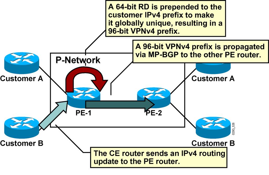
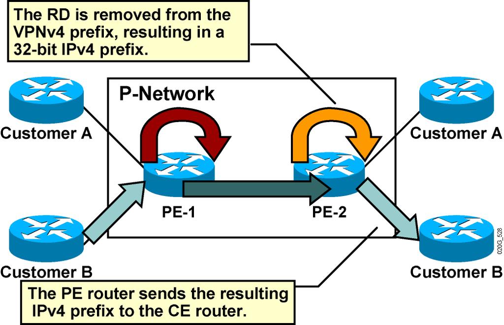
35 Route Distinguishers The 64-bit route distinguisher is prepended to an IPv4 address to make it globally unique. The resulting address is a VPNv4 address. VPNv4 addresses are exchanged between PE routers via BGP. BGP that supports address families other than IPv4 addresses is called MP-BGP. A similar process is used in IPv6: 64-bit route distinguisher is prepended to a 16-byte IPv6 address. The resulting 24-byte address is a unique VPNv6 address.
36 Route Distinguishers (Cont.)
37 Route Distinguishers (Cont.)
38 RDs: Usage in an MPLS VPN The RD has no special meaning. The RD is used only to make potentially overlapping IPv4 addresses globally unique. The RD is used as a VPN identifier, but this design could not support all topologies required by the customers.

39 Is the RD Enough? VoIP Service Sample Requirements: All sites of one customer need to communicate. Central sites of both customers need to communicate with VoIP gateways and other central sites. Other sites from different customers do not communicate with each other.

40 Example: Connectivity Requirements
41 RTs: Why Are They Needed? Some sites have to participate in more than one VPN. The RD cannot identify participation in more than one VPN. RTs were introduced in the MPLS VPN architecture to support complex VPN topologies. A different method is needed in which a set of identifiers can be attached to a route.
42 RTs: What Are They? RTs are additional attributes attached to VPNv4 BGP routes to indicate VPN membership. Extended BGP communities are used to encode these attributes. Extended communities carry the meaning of the attribute together with its value. Any number of RTs can be attached to a single route.
43 RTs: How Do They Work? Export RTs: Identifying VPN membership Appended to the customer route when it is converted into a VPNv4 route Import RTs: Associated with each virtual routing table Select routes to be inserted into the virtual routing table

44 RT and RD operation in an MPLS VPN

45 RT and RD operation in an MPLS VPN (cont.)
46 Impact of Complex VPN Topologies on Virtual Routing Tables A virtual routing table in a PE router can be used only for sites with identical connectivity requirements. Complex VPN topologies require more than one virtual routing table per VPN. As each virtual routing table requires a distinct RD value, the number of RDs in the MPLS VPN network increases.

47 Impact of Complex VPN Topologies on Virtual Routing Tables (Cont.)
48 MPLS VPN Technology Introducing the MPLS VPN Routing Model
49 MPLS VPN Routing Requirements CE routers have to run standard IP routing software. PE routers have to support MPLS VPN services and IP routing. P routers have no VPN routes.

50 MPLS VPN Routing: CE Router Perspective The CE routers run standard IP routing software and exchange routing updates with the PE router. EBGP, OSPF, RIPv2, EIGRP, and static routes are supported. The PE router appears as another router in the C-network.

51 MPLS VPN Routing: Overall Customer Perspective To the customer, the PE routers appear as core routers connected via a BGP backbone. The usual BGP and IGP design rules apply. The P routers are hidden from the customer.

52 MPLS VPN Routing: P Router Perspective P routers do not participate in MPLS VPN routing and do not carry VPN routes. P routers run backbone IGP with the PE routers and exchange information about global subnetworks (core links and loopbacks).

53 MPLS VPN Routing: PE Router Perspective PE routers: Exchange VPN routes with CE routers via per-vpn routing protocols Exchange core routes with P routers and PE routers via core IGP Exchange VPNv4 routes with other PE routers via MP-IBGP sessions
.")
54 Routing Tables on PE Routers PE routers contain a number of routing tables: The global routing table contains core routes (filled with core IGP) and Internet routes (filled with IPv4 BGP). The VRF tables contains routes for sites of identical routing requirements from local (IPv4 VPN) and remote (VPNv4 via MP-BGP) CE routers.
55 End-to-End Routing Update Flow PE routers receive IPv4 routing updates from CE routers and install them in the appropriate VRF table.
 PE routers export VPN routes from VRF tables into MP-BGP and propagate")
56 End-to-End Routing Update Flow (Cont.) PE routers export VPN routes from VRF tables into MP-BGP and propagate them as VPNv4 routes to other PE routers.
57 End-to-End Routing Update Flow: MP-BGP Update An MP-BGP update contains these elements: VPNv4 address Extended communities (route targets, optionally SOO) Label used for VPN packet forwarding Any other BGP attribute (for example, AS path, local preference, MED, standard community)
58 End-to-End Routing Update Flow (Cont.) The receiving PE router imports the incoming VPNv4 routes into the appropriate VRF based on route targets attached to the routes. The routes installed in the VRFs are propagated to the CE routers.
59 Route Distribution to CE Routers A route is installed in the site VRF if it matches the import route target attribute. Route distribution to CE sites is driven by the following: Route targets SOO attribute if defined
60 MPLS VPN Technology Forwarding MPLS VPN Packets

61 VPN Packet Forwarding Across an MPLS VPN Backbone: Approach 1 Approach 1: The PE routers will label the VPN packets with an LDP label for the egress PE router, and forward the labeled packets across the MPLS backbone. Results: The P routers perform the label switching, and the packet reaches the egress PE router. Because the egress PE router does not know which VRF to use for packet switching, the packet is dropped.

62 VPN Packet Forwarding Across an MPLS VPN Backbone: Approach 2 Approach 2: Result: The PE routers will label the VPN packets with a label stack, using the LDP label for the egress PE router as the top label, and the VPN label assigned by the egress PE router as the second label in the stack. The P routers perform label switching using the top label, and the packet reaches the egress PE router. The top label is removed. The egress PE router performs a lookup on the VPN label and forwards the packet toward the CE router.
63 VPN PHP Penultimate hop popping on the LDP label can be performed on the last P router. The egress PE router performs label lookup only on the VPN label, resulting in faster and simpler label lookup. IP lookup is performed only once in the ingress PE router.
64 VPN Label Propagation Question: How will the ingress PE router get the second label in the label stack from the egress PE router? Answer: Labels are propagated in MP-BGP VPNv4 routing updates.
 Step 1: Step 2: Step 3: A VPN label is assigned to every VPN route by the egress PE router.")
65 VPN Label Propagation (Cont.) Step 1: Step 2: Step 3: A VPN label is assigned to every VPN route by the egress PE router. The VPN label is advertised to all other PE routers in an MP-BGP update. A label stack is built in the VRF table.
66 MPLS VPN Implementation Configuring VRF Tables
67 VRF Configuration Tasks VRF configuration tasks: Create a VRF table Assign RD to the VRF Specify export and import route targets (Optional) Configure a VPN ID Assign interfaces to VRFs
68 Creating VRF Tables and Assigning RDs Router(config)# ip vrf name This command creates a new VRF or enters configuration of an existing VRF. VRF names are case-sensitive. VRF is not operational unless you configure RD. VRF names have only local significance. Router(config-vrf)# rd route-distinguisher This command assigns a route distinguisher to a VRF. You can use ASN:nn or A.B.C.D:nn format for RD. Each VRF in a PE router has to have a unique RD.
69 Specifying Export and Import Router(config-vrf)# route-target export RT RTs Specifies an RT to be attached to every route exported from this VRF to Multiprotocol Border Gateway Protocol Allows specification of many export RTs all to be attached to every exported route Router(config-vrf)# route-target import RT Specifies an RT to be used as an import filter (Only routes matching the RT are imported into the VRF.) Allows specification of many import RTs (any route where at least one RT attached to the route matches any import RT is imported into the VRF.) Because of implementation issues, at least one export route target must also be an import route target of the same VRF in Cisco IOS Release 12.4(T) and earlier.
70 Router(config-vrf)# route-target both RT Specifying Export and Import RTs (Cont.) In cases where the export RT matches the import RT, use this form of the route-target command. Sample router configuration for simple customer VPN: ip vrf Customer_ABC rd 65173:15 route-target export 65173:15 route-target import 65173:15
71 Router(config-if)# ip vrf forwarding vrf-name Assigning an Interface to a VRF Table This command associates an interface with the specified VRF. The existing IP address is removed from the interface when the interface is put into VRF the IP address must be reconfigured. CEF switching must be enabled on the interface. Sample router configuration: ip cef! interface serial 0/0 ip vrf forwarding Customer_ABC ip address

72 MPLS VPN Network Example The network supports two VPN customers. Customer A runs RIP and BGP with the service provider; customer B uses only RIP. Both customers use network

73 MPLS VPN Network Example (Cont.)
74 MPLS VPN Implementation Configuring an MP-BGP Session Between PE Routers
75 Configuring BGP Address Families The BGP process in an MPLS VPN-enabled router performs three separate tasks: Global BGP routes (Internet routing) are exchanged as in traditional BGP setup. VPNv4 prefixes are exchanged through MP-BGP. VPN routes are exchanged with CE routers through per- VRF External Border Gateway Protocol sessions. Address families (routing protocol contexts) are used to configure these three tasks in the same BGP process.
76 Router(config)# router bgp as-number Selects global BGP routing process Router(config-router)# address-family vpnv4 Selects configuration of VPNv4 prefix exchanges under MP-BGP sessions Router(config-router)# address-family ipv4 vrf vrf-name Configuring BGP Address Families (Cont.) Selects configuration of per-vrf PE-CE EBGP parameters
77 BGP Neighbors MP-BGP neighbors are configured under the BGP routing process: These neighbors need to be activated for each global address family that they support. Per-address-family parameters can be configured for these neighbors. VRF-specific EBGP neighbors are configured under corresponding address families.
78 Configuring MP-BGP MPLS VPN MP-BGP configuration steps: Configure MP-BGP neighbor under BGP routing process. Configure BGP address family VPNv4. Activate configured BGP neighbor for VPNv4 route exchange. Specify additional parameters for VPNv4 route exchange (filters, next hops, and so on).
79 Configuring MP-IBGP Router(config)# router bgp as-number neighbor ip-address remote-as as-number neighbor ip-address update-source interface-type interface-number All MP-BGP neighbors have to be configured under global BGP routing configuration. MP-IBGP sessions have to run between loopback interfaces. Router(config-router)# address-family vpnv4 This command starts configuration of MP-BGP routing for VPNv4 route exchange. The parameters that apply only to MP-BGP exchange of VPNv4 routes between already configured IBGP neighbors are configured under this address family.
80 Configuring MP-IBGP (Cont.) Router(config-router-af)# neighbor ip-address activate The BGP neighbor defined under BGP router configuration has to be activated for VPNv4 route exchange. Router(config-router-af)# neighbor ip-address next-hop-self The next-hop-self keyword can be configured on the MP-IBGP session for MPLS VPN configuration if EBGP is being run with a CE neighbor.
81 Router(config-router-af)# neighbor ip-address send-community [standard extended both] This command with the extended option is enabled by default by Cisco IOS software after the BGP neighbor has been activated for VPNv4 route exchange. The command can be used to enable propagation of standard BGP communities attached to VPNv4 prefixes. Usage guidelines: MP-BGP Community Propagation Extended BGP communities attached to VPNv4 prefixes have to be exchanged between MP-BGP neighbors for proper MPLS VPN operation. To propagate standard BGP communities between MP-BGP neighbors, use the both option.

82 MP-BGP BGP Community Propagation (Cont.)
83 Router(config)# Configuring per-vrf BGP router bgp as-number address-family ipv4 vrf vrf-name... Per-VRF BGP definitions... Routing Context Select per-vrf BGP context with the address-family command. All non-bgp per-vrf routes have to be redistributed into a per-vrf BGP context to be propagated by MP- BGP to other PE routers (for example redistribute connected).
84 Configuring Per-VRF Static Routes Router(config)# ip route vrf vrf-name prefix mask [interface interfacenumber] [next-hop-address] This command configures per-vrf static routes. The route is entered in the VRF table. You must specify a next-hop IP address if you are not using a point-to-point interface. Sample router configuration: ip route vrf Customer_ABC serial0/ ! router bgp address-family ipv4 vrf Customer_ABC redistribute static
85 MPLS VPN Implementation Monitoring MPLS VPN Operations
86 Monitoring VRFs Router# show ip vrf Displays the list of all VRFs configured in the router Router# show ip vrf detail Displays detailed VRF configuration Router# show ip vrf interfaces Displays interfaces associated with VRFs
87 Monitoring VRFs: show ip vrf Router#show ip vrf Name Default RD Interfaces SiteA2 103:30 Serial1/0.20 SiteB 103:11 Serial1/0.100 SiteX 103:20 Ethernet0/0 Router#
88 Monitoring VRFs: show ip vrf detail Router#show ip vrf detail VRF SiteA2; default RD 103:30 Interfaces: Serial1/0.20 Connected addresses are not in global routing table No Export VPN route-target communities Import VPN route-target communities RT:103:10 No import route-map Export route-map: A2 VRF SiteB; default RD 103:11 Interfaces: Serial1/0.100 Connected addresses are not in global routing table Export VPN route-target communities RT:103:11 Import VPN route-target communities RT:103:11 RT:103:20 No import route-map No export route-map
89 Monitoring VRFs: show ip vrf interfaces Router#show ip vrf interfaces Interface IP-Address VRF Protocol Serial1/ SiteA2 up Serial1/ SiteB up Ethernet0/ SiteX up
90 Monitoring VRF Routing Router# show ip protocols vrf vrf-name Displays the routing protocols configured in a VRF Router# show ip route vrf vrf-name Displays the VRF routing table Router# show ip bgp vpnv4 vrf vrf-name Displays per-vrf BGP parameters
91 Monitoring VRF Routing: show ip protocols vrf Router#show ip protocol vrf SiteX Routing Protocol is "rip" Sending updates every 30 seconds, next due in 10 seconds Invalid after 180 seconds, hold down 180, flushed after 240 Outgoing update filter list for all interfaces is Incoming update filter list for all interfaces is Redistributing: rip, bgp Default version control: send version 2, receive version 2 Interface Send Recv Triggered RIP Key-chain Ethernet0/0 2 2 Routing for Networks: Routing Information Sources: Gateway Distance Last Update Distance: (default is 120)
92 Router#show ip route vrf SiteA2 Codes: C - connected, S - static, I - IGRP, R - RIP, M - mobile, B - BGP D - EIGRP, EX - EIGRP external, O - OSPF, IA - OSPF inter area N1 - OSPF NSSA external type 1, N2 - OSPF NSSA external type 2 E1 - OSPF external type 1, E2 - OSPF external type 2, E - EGP i - IS-IS, L1 - IS-IS level-1, L2 - IS-IS level-2, * - candidate default, U - per-user static route, o - ODR P - periodic downloaded static route Gateway of last resort is not set Monitoring VRF Routing: show ip route vrf O /24 [110/782] via , 02:52:13, Serial1/ /32 is subnetted, 1 subnets O [110/782] via , 02:52:13, Serial1/ /32 is subnetted, 1 subnets B [200/1] via , 01:14:32 B /24 [200/782] via , 02:05:38 B /24 [200/1] via , 02:05:38 B /24 [200/1] via , 01:14:32 rest deleted
93 Monitoring VRF Routing: show ip bgp vpnv4 vrf neighbors Router#show ip bgp vpnv4 vrf SiteB neighbors BGP neighbor is , vrf SiteB, remote AS 65032, external link BGP version 4, remote router ID BGP state = Established, up for 02:01:41 Last read 00:00:56, hold time is 180, keepalive interval is 60 seconds Neighbor capabilities: Route refresh: advertised and received Address family IPv4 Unicast: advertised and received Received 549 messages, 0 notifications, 0 in queue Sent 646 messages, 0 notifications, 0 in queue Route refresh request: received 0, sent 0 Minimum time between advertisement runs is 30 seconds For address family: VPNv4 Unicast Translates address family IPv4 Unicast for VRF SiteB BGP table version 416, neighbor version 416 Index 4, Offset 0, Mask 0x10 Community attribute sent to this neighbor 2 accepted prefixes consume 120 bytes Prefix advertised 107, suppressed 0, withdrawn 63 rest deleted
94 Monitoring MP-BGP Sessions Router# show ip bgp neighbors This command displays global BGP neighbors and the protocols negotiated with these neighbors.
95 Monitoring MP-BGP Sessions: show ip bgp neighbors Router#show ip bgp neighbor BGP neighbor is , remote AS 3, internal link BGP version 4, remote router ID BGP state = Established, up for 02:15:33 Last read 00:00:33, hold time is 180, keepalive interval is 60 seconds Neighbor capabilities: Route refresh: advertised and received Address family IPv4 Unicast: advertised and received Address family VPNv4 Unicast: advertised and received Received 1417 messages, 0 notifications, 0 in queue Sent 1729 messages, 2 notifications, 0 in queue Route refresh request: received 9, sent 29 Minimum time between advertisement runs is 5 seconds For address family: IPv4 Unicast BGP table version 188, neighbor version 188 Index 2, Offset 0, Mask 0x4 1 accepted prefixes consume 36 bytes Prefix advertised 322, suppressed 0, withdrawn Continued
96 Monitoring MP-BGP Sessions: show ip bgp neighbors (Cont.) Router#show ip bgp neighbor Continued For address family: VPNv4 Unicast BGP table version 416, neighbor version 416 Index 2, Offset 0, Mask 0x4 NEXT_HOP is always this router Community attribute sent to this neighbor 6 accepted prefixes consume 360 bytes Prefix advertised 431, suppressed 0, withdrawn 113 Connections established 7; dropped 6 Last reset 02:18:33, due to Peer closed the session... Rest deleted
97 Monitoring an MP-BGP Router# show ip bgp vpnv4 all VPNv4 Table Displays whole VPNv4 table. Router# show ip bgp vpnv4 vrf vrf -name Displays only BGP parameters (routes or neighbors) associated with specified VRF. Any BGP show command can be used with these parameters. Router# show ip bgp vpnv4 rd route-distinguisher Displays only BGP parameters (routes or neighbors) associated with the specified RD.
98 Monitoring an MP-BGP VPNv4 Table: show ip bgp vpnv4 vrf-name Router#show ip bgp vpnv4 vrf SiteA2 BGP table version is 416, local router ID is Status codes: s suppressed, d damped, h history, * valid, > best, i - internal Origin codes: i - IGP, e - EGP,? - incomplete Network Next Hop Metric LocPrf Weight Path Route Distinguisher: 103:30 (default for vrf SiteA2) *> / ? *>i / ? *>i / ? *>i / i *> / ? *>i i *> ? *>i / ? *>i / ? *>i ? *>i ?
99 Monitoring an MP-BGP VPNv4 Table: show ip bgp vpnv4 rd route-distinguisher Router#show ip bgp vpnv4 rd 103: BGP routing table entry for 103:30: /32, version 164 Paths: (1 available, best #1, table SiteA2) Not advertised to any peer Local, imported path from 103:10: / (metric 10) from ( ) Origin incomplete, metric 1, localpref 100, valid, internal, best Extended Community: RT:103:10
100 Router# show ip cef vrf vrf-name Monitoring per-vrf CEF and LFIB Structures Displays per-vrf CEF table Router# show ip cef vrf vrf-name ip-prefix detail Displays details of an individual CEF entry, including label stack Router# show mpls forwarding vrf vrf-name Displays labels allocated by an MPLS VPN for routes in the specified VRF
101 Monitoring per-vrf CEF and LFIB Structures (Cont.) Router#show ip cef vrf SiteA detail /32, version 57, cached adjacency to Serial1/0.2 0 packets, 0 bytes tag information set local tag: VPN-route-head fast tag rewrite with Se1/0.2, point2point, tags imposed: {26 39} via , 0 dependencies, recursive next hop , Serial1/0.2 via /32 valid cached adjacency tag rewrite with Se1/0.2, point2point, tags imposed: {26 39} The show ip cef command can also display the label stack associated with the MP-IBGP route.
102 Monitoring per-vrf CEF and LFIB Structures (Cont.) Router#show mpls forwarding vrf SiteA2 Local Outgoing Prefix Bytes tag Outgoing Next Hop tag tag or VC or Tunnel Id switched interface 26 Aggregate /30[V] 0 37 Untagged /32[V] 0 Se1/0.20 point2point 38 Untagged /24[V] 0 Se1/0.20 point2point Router#show mpls forwarding vrf SiteA2 tags 37 detail Local Outgoing Prefix Bytes tag Outgoing Next Hop tag tag or VC or Tunnel Id switched interface 37 Untagged /32[V] 0 Se1/0.20 point2point MAC/Encaps=0/0, MTU=1504, Tag Stack{} VPN route: SiteA2 Per-packet load-sharing
103 Router# Monitoring Labels Associated with VPNv4 Routes show ip bgp vpnv4 [ all rd value vrf vrf-name ] labels Displays labels associated with VPNv4 routes Router#show ip bgp vpnv4 all labels Network Next Hop In label/out label Route Distinguisher: 100:1 (vrf1) /nolabel /nolabel /nolabel /nolabel nolabel/26
104 Other MPLS VPN Monitoring Router# telnet host /vrf vrf-name Commands Performs PE-CE Telnet through specified VRF Router# ping vrf vrf-name ip-address Performs ping based on VRF routing table Router# trace vrf vrf-name ip-address Performs VRF-based traceroute
105 MPLS VPN Implementation Troubleshooting MPLS VPNs
106 Preliminary Steps in MPLS VPN Troubleshooting Perform basic MPLS troubleshooting: Is CEF enabled? Are labels for IGP routes generated and propagated? Are large labeled packets propagated across the MPLS backbone (maximum transmission unit issues)?
107 Verifying the Routing Information Flow Verify the routing information flow: Are CE routes received by a PE router? Are routes redistributed into MP-BGP with proper extended communities? Are VPNv4 routes propagated to other PE routers? Is the BGP route selection process working correctly? Are VPNv4 routes inserted into VRFs on other PE routers? Are VPNv4 routes redistributed from BGP into the PE-CE routing protocol? Are IPv4 routes propagated to other CE routers?
108 Validating CE-to-PE Routing Information Flow Are CE routes received by the PE router? Verify with the show ip route vrf vrf-name command on PE-1. Perform traditional routing protocol troubleshooting if needed.
109 Validating PE-to-PE Routing Information Flow Are routes redistributed into MP-BGP with proper extended communities? Verify with the show ip bgp vpnv4 vrf vrf-name ip-prefix command on PE-1. Troubleshoot with debug ip bgp commands.
110 Validating PE-to-PE Routing Information Flow (Cont.) Are VPNv4 routes propagated to other PE routers? Verify with the show ip bgp vpnv4 all ip-prefix/length command. Troubleshoot PE-to-PE connectivity with traditional BGP troubleshooting tools.
111 Validating PE-to-PE Routing Information Flow (Cont.) Is the BGP route selection process working correctly on PE-2? Verify with the show ip bgp vpnv4 vrf vrf-name ip-prefix command. Change local preference or weight settings if needed. Do not change MED if you are using IGP-BGP redistribution on PE-2.
112 Validating PE-to-PE Routing Information Flow (Cont.) Are VPNv4 routes inserted into VRFs on PE-2? Verify with the show ip route vrf command. Troubleshoot with the show ip bgp ip-prefix and show ip vrf detail command. Perform additional BGP troubleshooting if needed.
113 Validating PE-to-PE Routing Information Flow (Cont.) Are VPNv4 routes redistributed from BGP into the PE-CE routing protocol? Verify redistribution configuration is the IGP metric specified? Perform traditional routing protocol troubleshooting.

114 Validating PE-to-CE Routing Information Flow Are VPNv4 routes propagated to other CE routers? Verify with the show ip route command on CE-Spoke. Alternatively, do CE-Spokes have a default route toward PE-2? Perform traditional routing protocol troubleshooting if needed.
115 Verifying the Data Flow Verify proper data flow: Is CEF enabled on the ingress PE router interface? Is the CEF entry correct on the ingress PE router? Is there an end-to-end label switched path tunnel (LSP tunnel) between PE routers? Is the LFIB entry on the egress PE router correct?
116 Validating CEF Status Is CEF enabled on the ingress PE router interface? Verify with the show cef interface command. MPLS VPN needs CEF enabled on the ingress PE router interface for proper operation. CEF might become disabled because of additional features deployed on the interface.
117 Validating CEF Status: show cef interface Router#show cef interface serial 1/0.20 Serial1/0.20 is up (if_number 18) Internet address is /30 ICMP redirects are always sent Per packet loadbalancing is disabled IP unicast RPF check is disabled Inbound access list is not set Outbound access list is not set IP policy routing is disabled Interface is marked as point to point interface Hardware idb is Serial1/0 Fast switching type 5, interface type 64 IP CEF switching enabled IP CEF VPN Fast switching turbo vector VPN Forwarding table "SiteA2" Input fast flags 0x1000, Output fast flags 0x0 ifindex 3(3) Slot 1 Slot unit 0 VC -1 Transmit limit accumulator 0x0 (0x0) IP MTU 1500
118 Validating CEF Status Is the CEF entry correct on the ingress PE router? Display the CEF entry with the show ip cef vrf vrf-name ip-prefix/length detail command. Verify the label stack in the CEF entry.
119 Validating the End-to-End Label Switched Path Is there an end-to-end LSP tunnel between PE routers? Check summarization issues BGP next hop should be reachable as host route. Quick check if TTL propagation is disabled, the trace from PE-2 to PE-1 should contain only one hop. If needed, check LFIB values hop by hop. Check for MTU issues on the path MPLS VPN requires a larger label header than pure MPLS.
120 Validating the LFIB Status Is the LFIB entry on the egress PE router correct? Find out the second label in the label stack on PE-2 with the show ip cef vrf vrf-name ip-prefix detail command. Verify correctness of LFIB entry on PE-1 with the show mpls forwarding vrf vrf-name value detail command.
121 Any Transport over MPLS (AToM) Introduction to Any Transport over MPLS (AToM)
122 AToM Overview Many service providers offer Layer 2 transport services. Overlay VPNs were built using ATM or Frame Relay PVCs. Building both a Layer 2 and a Layer 3 network is costly. Service providers want to unify VPN services and Internet services in a single network: an MPLS- based network. However, some customers still want Layer 2 connections (Ethernet VLANs or PVCs).
123 AToM Overview (Cont.) Benefits Incorporates Layer 2 and Layer 3 services over a common infrastructure Scalability: MPLS does not keep state information about virtual circuits inside core Maintains support for existing services while migrating to MPLS Customer sites independent of service provider backbone
124 AtoM Overview (Cont.) MPLS backbone CE-A1 PE-Site-X PE-Site-Y CE-A2 AToM is not designed specifically for switch replacement. It is used for interconnecting and transporting a traffic POP across an MPLS core network.
125 Transport Types AToM enables the following types of Layer 2 frames and cells to be directed across an MPLS backbone: Ethernet, Ethernet VLAN ATM adaptation layer 5 (AAL5) ATM cell relay Frame Relay Point-to-Point Protocol (PPP) High-Level Data Link Control (HDLC)
126 How AToM Works AToM frames are carried across an MPLS backbone in the following manner: Ingress and egress interfaces are non-mpls interfaces. Ingress PE encapsulates frame into MPLS; egress PE decapsulates. Label stack of two labels is used (similar to an MPLS VPN). Topmost label ( tunnel label ) used for LSP PE to PE. Second label ( VC label ) identifies outgoing interface in the egress PE. LDP has been extended to carry virtual circuit forwarding equivalence class (VC FEC). A directed (multihop) LDP session is used from PE to PE.
127 How AToM Works (Cont.) VC LDP LSP LSP VC The IGP and the LDP between directly connected LSRs establish one LSP in each direction. A directed LDP session between PE routers is established.
128 How AToM Works (Cont.) 21 VC pop 23 LDP between directly connected LSRs generates an LSP. The egress PE allocates VC label 17. The directed LDP session between PE routers propagates the VC label.
129 How AToM Works (Cont.) dlci dlci 202 The ingress PE receives a frame on DLCI 101. The frame is encapsulated and forwarded along the LSP. The egress PE reconstructs the frame.
130 AToM Control Word Label (LDP) EXP 0 TTL Label (VC) EXP 1 TTL 0000 Flags Length Sequence Number Layer 2 PDU The control word is optional. It is transmitted after the label(s) and before the Layer 2 PDU. Flag field carries different bits for different Layer 2 protocols: Frame Relay: FECN, BECN, DE, C/R ATM: AAL5 or cell, EFCI, CLP, C/R Sequence number 0 indicates that no sequencing is done.
131 Any Transport over MPLS (AToM) Configuring AToM on Cisco IOS Platforms
132 MTU Issues AToM transport of Frame Relay, Ethernet, and AAL5 does not allow packets to be fragmented and reassembled. Ensure that the MTU of all intermediate links between endpoints is sufficient to carry the largest Layer 2 frame received. The ingress and egress PE routers must have the same MTU value.
133 AToM MTU calculation: Core MTU >= (Edge MTU + Transport Header Size + AToM header + (MPLS label stack * MPLS label size)) Transport Type AAL5 Ethernet VLAN Ethernet Port Frame Relay DLCI HDLC PPP Transport Header Size 0-32 bytes 18 bytes 14 bytes 2 bytes for Cisco encapsulation, 8 bytes for IETF encapsulation 4 bytes 4 bytes
134 AToM Configuration AToM is configured using the following steps: The PE routers must have a /32 address assigned to their loopbacks. MPLS must be enabled in the core. Make sure MTU is large enough in the core. Enable Layer 2 frame transport in both endpoint PE routers. Make sure MTU is same on both endpoint interfaces.
135 router(config)# mpls ldp router-id interface [force] AToM Configuration: Configuring the LDP ID Specifies a preferred interface for determining the Label Distribution Protocol (LDP) router ID. Parameters: interface Causes the IP address of the specified interface to be used as the LDP router ID, provided that the interface is operational. force Alters the behavior of the mpls ldp router-id command to force the use of the named interface as the LDP router ID.
136 AToM Configuration router(config-if)# xconnect destination vc-id encapsulation mpls Enables Layer 2 routing over an emulated VC across the MPLS cloud Parameters: destination Specifies the IP address of the remote PE router loopback. vc-id Assigns a VC ID to an interface. The VC ID must be unique to each virtual circuit.
137 EoMPLS Configuration MPLS Backbone Ethernet interface CE-A1 PE-Site-X PE-Site-Y CE-A2 The two customer devices, CE-A1 and CE-A2, exchange Ethernet frames. PE-Site-X takes whatever Ethernet frames that arrive on the Ethernet interface and forwards them as an MPLS packet across the MPLS backbone to PE-Site-Y. The EoMPLS service does not do MAC address learning and filtering and does not take part in the Spanning Tree Protocol. PE-Site-Y removes MPLS headers and propagates the Ethernet frame out on the Ethernet interface on its side.
138 EoMPLS Configuration MPLS Backbone (Cont.) Ethernet VLAN CE-A1 PE-Site-X PE-Site-Y CE-A2 The two customer devices, CE-A1 and CE-A2, exchange Ethernet frames. PE-Site-X takes whatever Ethernet frames that arrive on the VLAN subinterface and forwards them as an MPLS packet across the MPLS backbone to PE-Site-Y. The EoMPLS service does not do MAC address learning and filtering and does not take part in the Spanning Tree Protocol. These functions can be performed by the Cisco catalyst 6000 series switches. PE-Site-Y removes MPLS headers and propagates the Ethernet frame out on the VLAN subinterface on its side.
139 EoMPLS Configuration (Cont.) MPLS Backbone CE-A1 PE-Site-X PE-Site-Y CE-A2 interface Loopback0 ip address ! interface GigabitEthernet0/0 no ip address! interface GigabitEthernet0/0.2 encapsulation dot1q 200 хconnect encapsulation mpls interface Loopback0 ip address ! interface GigabitEthernet1/0 no ip address! interface GigabitEthernet1/0.2 encapsulation dot1q 201 хconnect encapsulation mpls
140 PPP over MPLS Configuration MPLS Backbone PPP link CE-A1 PE-Site-X PE-Site-Y CE-A2 PPP over MPLS enables two CE devices to use a PPP link-level connection across the MPLS backbone.
141 PPP over MPLS Configuration MPLS Backbone (Cont.) CE-A1 PE-Site-X PE-Site-Y CE-A2 interface Loopback0 ip address ! interface Serial1/0 no ip address encapsulation ppp хconnect encapsulation mpls interface Loopback0 ip address ! interface serial1/0 no ip address encapsulation ppp хconnect encapsulation mpls
142 MPLS Backbone HDLC over MPLS Configuration HDLC Link CE-A1 PE-Site-X PE-Site-Y CE-A2 HDLC over MPLS enables two CE devices to use a Cisco HDLC link-level connection across the MPLS backbone.
143 MPLS Backbone HDLC over MPLS Configuration (Cont.) CE-A1 PE-Site-X PE-Site-Y CE-A2 interface Loopback0 ip address ! interface Serial1/0 no ip address encapsulation hdlc hdlc хconnect encapsulation mpls interface Loopback0 ip address ! interface serial1/0 no ip address encapsulation hdlc хconnect encapsulation mpls
144 Any Transport over MPLS (AToM) Monitoring AToM on Cisco IOS Platforms
145 Monitoring AToM show mpls l2transport vc show mpls l2transport vc detail show mpls l2transport summary debug mpls l2transport vlan control
146 show mpls l2transport vc router# show mpls l2transport vc [vcid vc-id] [vc-id-min vc-id-max] [interface name [localcircuit-id]] [destination ip-address name] [detail] Displays the state of VCs on a router
147 show mpls l2transport vc MPLS Backbone (Cont.) CE-A1 PE-Site-X PE-Site-Y CE-A2 PE-site-X# show mpls l2transport vc Transport Client VC Local Remote Tunnel VC ID Intf State VC Label VC Label Label 4 vl4 UP vl101 UP
148 show mpls l2transport vc MPLS Backbone summary CE-A1 PE-Site-X PE-Site-Y CE-A2 PE-Site-X# show mpls l2transport vc summary MPLS interface VC summary: interface: Gi8/1, programmed imposition vcs: 1 interface: Gi8/3, programmed imposition vcs: 1 VC summary (active/non-active) by destination: destination: , Number of locally configured vc(s): 2
149 show mpls l2transport MPLS Backbone summary CE-A1 PE-Site-X PE-Site-Y CE-A2 PE-Site-X# show mpls l2transport vc 2 detail VC ID: 2, Local Group ID: 8, Remote Group ID: 8 (VC is up) Client Intf: Vl2 is up, Destination: , Peer LDP Ident: :0 Local VC Label: 21, Remove VC Label: 21, Tunnel Label: 22 Outgoing Interface: Gi3/2, Next Hop: Local MTU: 1500, Remote MTU: 1500 Imposition: LC Programmed, Current Imposition/Disposition Slot: 3/32 Packet Totals(in/out): / Byte Totals(in/out): /
150 router# debug mpls l2transport vlan control debug mpls l2transport vlan control To enable debug messages about the control of traffic transported between Layer 2 VLAN and MPLS, use the debug mpls l2transport vlan control EXEC command. To disable the debug messages about transport control, use the no form of this command.
Securizarea Calculatoarelor și a Rețelelor 32. Tehnologia MPLS VPN
 Platformă de e-learning și curriculă e-content pentru învățământul superior tehnic Securizarea Calculatoarelor și a Rețelelor 32. Tehnologia MPLS VPN MPLS VPN 5-ian-2010 What this lecture is about: IP
MPLS VPN. 5 ian 2010
 MPLS VPN 5 ian 2010 What this lecture is about: IP CEF MPLS architecture What is MPLS? MPLS labels Packet forwarding in MPLS MPLS VPNs 3 IP CEF & MPLS Overview How does a router forward packets? Process
Multiprotocol Label Switching Virtual Private Network
 Anas Al-Selwi Multiprotocol Label Switching Virtual Private Network Helsinki Metropolia University of Applied Sciences Bachelor of Engineering Information Technology Thesis 08 May 2013 Abstract Author(s)
IPv6 Switching: Provider Edge Router over MPLS
 Multiprotocol Label Switching (MPLS) is deployed by many service providers in their IPv4 networks. Service providers want to introduce IPv6 services to their customers, but changes to their existing IPv4
Configuring MPLS and EoMPLS
 37 CHAPTER This chapter describes how to configure multiprotocol label switching (MPLS) and Ethernet over MPLS (EoMPLS) on the Catalyst 3750 Metro switch. MPLS is a packet-switching technology that integrates
MPLS VPN--Inter-AS Option AB
 The feature combines the best functionality of an Inter-AS Option (10) A and Inter-AS Option (10) B network to allow a Multiprotocol Label Switching (MPLS) Virtual Private Network (VPN) service provider
Cisco Training - HD Telepresence MPLS: Implementing Cisco MPLS V3.0. Upcoming Dates. Course Description. Course Outline
 Cisco Training - HD Telepresence MPLS: Implementing Cisco MPLS V3.0 From the technology basics to advanced VPN configuration. $3,995.00 5 Days Upcoming Dates Dec 10 - Dec 14 Mar 25 - Mar 29 Course Description
MPLS VPN Inter-AS Option AB
 First Published: December 17, 2007 Last Updated: September 21, 2011 The feature combines the best functionality of an Inter-AS Option (10) A and Inter-AS Option (10) B network to allow a Multiprotocol
MPLS VPN C H A P T E R S U P P L E M E N T. BGP Advertising IPv4 Prefixes with a Label
 7 C H A P T E R S U P P L E M E N T This online supplement of Chapter 7 focuses on two important developments. The first one is Inter-Autonomous. Inter-Autonomous is a concept whereby two service provider
IPv6 Switching: Provider Edge Router over MPLS
 Multiprotocol Label Switching (MPLS) is deployed by many service providers in their IPv4 networks. Service providers want to introduce IPv6 services to their customers, but changes to their existing IPv4
MPLS VPN Carrier Supporting Carrier Using LDP and an IGP
 MPLS VPN Carrier Supporting Carrier Using LDP and an IGP Multiprotocol Label Switching (MPLS) Virtual Private Network (VPN) Carrier Supporting Carrier (CSC) enables one MPLS VPN-based service provider
MPLS VPN Inter-AS with ASBRs Exchanging VPN-IPv4 Addresses
 MPLS VPN Inter-AS with ASBRs Exchanging VPN-IPv4 Addresses The Multiprotocol Label Switching (MPLS) VPN Inter-AS with Autonomous System Boundary Routers (ASBRs) Exchanging VPN-IPv4 Addresses feature allows
MPLS VPN Carrier Supporting Carrier IPv4 BGP Label Distribution
 MPLS VPN Carrier Supporting Carrier IPv4 BGP Label Distribution This feature lets you configure your carrier supporting carrier network to enable Border Gateway Protocol (BGP) to transport routes and Multiprotocol
Deploy MPLS L3 VPN. APNIC Technical Workshop October 23 to 25, Selangor, Malaysia Hosted by:
 Deploy MPLS L3 VPN APNIC Technical Workshop October 23 to 25, 2017. Selangor, Malaysia Hosted by: Issue Date: [201609] Revision: [01] Acknowledgement Cisco Systems Course Outline MPLS L3 VPN Models L3
MPLS VPN Carrier Supporting Carrier Using LDP and an IGP
 MPLS VPN Carrier Supporting Carrier Using LDP and an IGP Last Updated: December 14, 2011 Multiprotocol Label Switching (MPLS) Virtual Private Network (VPN) Carrier Supporting Carrier (CSC) enables one
MPLS Introduction. (C) Herbert Haas 2005/03/11
 Herbert Haas 2005/03/11") MPLS Introduction MPLS (C) Herbert Haas 2005/03/11 Terminology LSR LER FEC LSP FIB LIB LFIB TIB PHP LDP TDP RSVP CR-LDP Label Switch Router Label Edge Router Forwarding Equivalent Class Label Switched
MPLS Introduction MPLS (C) Herbert Haas 2005/03/11 Terminology LSR LER FEC LSP FIB LIB LFIB TIB PHP LDP TDP RSVP CR-LDP Label Switch Router Label Edge Router Forwarding Equivalent Class Label Switched
MPLS VPN Carrier Supporting Carrier IPv4 BGP Label Distribution
 MPLS VPN Carrier Supporting Carrier IPv4 BGP Label Distribution This feature enables you to configure your carrier supporting carrier network to enable Border Gateway Protocol (BGP) to transport routes
CCIE R&S Techtorial MPLS
 CCIE R&S Techtorial MPLS Ing. Tomáš Kelemen Partner Systems Engineer CCIE #24395 Ing. Peter Mesjar Systems Engineer CCIE #17428 2011 Cisco Systems, Inc. All rights reserved. 1 Agenda Introduction to MPLS
BGP Best External. Finding Feature Information
 The feature provides the network with a backup external route to avoid loss of connectivity of the primary external route. The feature advertises the most preferred route among those received from external
Multiprotocol Label Switching (MPLS)
") 36 CHAPTER Prerequisites for MPLS, page 36-1 Restrictions for MPLS, page 36-1 Information About MPLS, page 36-2 Default Settings for MPLS, page 36-7 How to Configure MPLS Features, page 36-7 Configuration
36 CHAPTER Prerequisites for MPLS, page 36-1 Restrictions for MPLS, page 36-1 Information About MPLS, page 36-2 Default Settings for MPLS, page 36-7 How to Configure MPLS Features, page 36-7 Configuration
MPLS VPN Multipath Support for Inter-AS VPNs
 The feature supports Virtual Private Network (VPN)v4 multipath for Autonomous System Boundary Routers (ASBRs) in the interautonomous system (Inter-AS) Multiprotocol Label Switching (MPLS) VPN environment.
Configuring MPLS, MPLS VPN, MPLS OAM, and EoMPLS
 CHAPTER 43 Configuring MPLS, MPLS VPN, MPLS OAM, and EoMPLS This chapter describes how to configure multiprotocol label switching (MPLS) and Ethernet over MPLS (EoMPLS) on the Cisco ME 3800X and ME 3600X
OSPF Sham-Link Support for MPLS VPN
 Feature History Release Modification 12.2(8)T This feature was introduced. This module describes how to configure and use a sham-link to connect Virtual Private Network (VPN) client sites that run the
MPLS опорни мрежи MPLS core networks
 MPLS опорни мрежи MPLS core networks Николай Милованов/Nikolay Milovanov http://niau.org Objectives Identify the drawbacks of traditional IP routing Describe basic MPLS concepts and LSR types. MPLS Labels
Implementing MPLS Layer 3 VPNs
 A Multiprotocol Label Switching (MPLS) Layer 3 Virtual Private Network (VPN) consists of a set of sites that are interconnected by means of an MPLS provider core network. At each customer site, one or
 26 CHAPTER Virtual Private Networks (VPNs) provide a secure way for customers to share bandwidth over an ISP backbone network. A VPN is a collection of sites sharing a common routing table. A customer
Multi-VRF Support. Finding Feature Information. Prerequisites for Multi-VRF Support
 The feature allows you to configure and maintain more than one instance of a routing and forwarding table within the same customer edge (CE) device. Finding Feature Information, page 1 Prerequisites for,
ibgp Multipath Load Sharing
 ibgp Multipath Load haring Feature History Release 12.2(2)T 12.2(14) Modification This feature was introduced. This feature was integrated into. This feature module describes the ibgp Multipath Load haring
AToM (Any Transport over MPLS)
") I N D E X A AAL5 over MPLS operation, 459 460 configuration, 462 463 flowchart configuration, 461 PE router, 461 provider router, 461 verification, 463 465 AAL5 to VLAN Interworking, 515 517 AC (Attachment
I N D E X A AAL5 over MPLS operation, 459 460 configuration, 462 463 flowchart configuration, 461 PE router, 461 provider router, 461 verification, 463 465 AAL5 to VLAN Interworking, 515 517 AC (Attachment
Exam : Title : BGP + MPLS Exam (BGP + MPLS)
") Exam : 642-691 Title : BGP + MPLS Exam (BGP + MPLS) Ver : 09-19-2008 QUESTION 1: Every time a flap occurs on a route, the route receives A. 750 per-flap penalty points which are user configurable B. 1500
Exam : 642-691 Title : BGP + MPLS Exam (BGP + MPLS) Ver : 09-19-2008 QUESTION 1: Every time a flap occurs on a route, the route receives A. 750 per-flap penalty points which are user configurable B. 1500
GRE Tunnel with VRF Configuration Example
 GRE Tunnel with VRF Configuration Example Document ID: 46252 Contents Introduction Prerequisites Requirements Components Used Conventions Configure Network Diagram Configurations Verify Troubleshoot Caveats
Configuring IPv6 Provider Edge over MPLS (6PE)
") Finding Feature Information, page 1 Configuring 6PE, page 1 Finding Feature Information Your software release may not support all the features documented in this module. For the latest caveats and feature
Finding Feature Information, page 1 Configuring 6PE, page 1 Finding Feature Information Your software release may not support all the features documented in this module. For the latest caveats and feature
Configuring MPLS L2VPN
 Contents Configuring MPLS L2VPN 1 MPLS L2VPN overview 1 Basic concepts of MPLS L2VPN 2 Implementation of MPLS L2VPN 2 MPLS L2VPN configuration task list 4 Configuring MPLS L2VPN 5 Configuring CCC MPLS
Configuring MPLS L3VPN
 Contents Configuring MPLS L3VPN 1 MPLS L3VPN overview 1 Introduction to MPLS L3VPN 1 MPLS L3VPN concepts 2 MPLS L3VPN packet forwarding 5 MPLS L3VPN networking schemes 5 MPLS L3VPN routing information
MPLS VPN Route Target Rewrite
 The feature allows the replacement of route targets on incoming and outgoing Border Gateway Protocol (BGP) updates Typically, Autonomous System Border Routers (ASBRs) perform the replacement of route targets
InterAS Option B. Information About InterAS. InterAS and ASBR
 This chapter explains the different InterAS option B configuration options. The available options are InterAS option B, InterAS option B (with RFC 3107), and InterAS option B lite. The InterAS option B
PASS4TEST. IT Certification Guaranteed, The Easy Way! We offer free update service for one year
 PASS4TEST IT Certification Guaranteed, The Easy Way \ http://www.pass4test.com We offer free update service for one year Exam : 642-691 Title : CCIP BGP + MPLS Exam (BGP + MPLS) Vendors : Cisco Version
Configuring Virtual Private LAN Services
 Virtual Private LAN Services (VPLS) enables enterprises to link together their Ethernet-based LANs from multiple sites via the infrastructure provided by their service provider. This module explains VPLS
WAN Edge MPLSoL2 Service
 4 CHAPTER While Layer 3 VPN services are becoming increasing popular as a primary connection for the WAN, there are a much larger percentage of customers still using Layer 2 services such Frame-Relay (FR).
MPLS VPN Inter-AS IPv4 BGP Label Distribution
 MPLS VPN Inter-AS IPv4 BGP Label Distribution This feature enables you to set up a Virtual Private Network (VPN) service provider network so that the autonomous system boundary routers (ASBRs) exchange
MPLS VPN Half-Duplex VRF
 The feature provides scalable hub-and-spoke connectivity for subscribers of an Multiprotocol Label Switching (MPLS) Virtual Private Network (VPN) service. This feature addresses the limitations of hub-and-spoke
Configuring Multicast VPN Inter-AS Support
 Configuring Multicast VPN Inter-AS Support Last Updated: December 23, 2011 The Multicast VPN Inter-AS Support feature enables Multicast Distribution Trees (MDTs) used for Multicast VPNs (MVPNs) to span
MPLS for R&S CCIE Candidates
 MPLS for R&S CCIE Candidates Johnny Bass CCIE #6458 2 About the Presenter Johnny Bass Networking industry since the late 1980s CCIE R&S #6458 CCSI 97168 Cisco 360 R&S Master Instructor Course director
Configuring VRF-lite CHAPTER
 CHAPTER 36 Virtual Private Networks (VPNs) provide a secure way for customers to share bandwidth over an ISP backbone network. A VPN is a collection of sites sharing a common routing table. A customer
WORKSHOP MPLS.
 WORKSHOP MPLS fbolanos@cisco.com 2001, Cisco Systems, Inc. All rights reserved. 1 MPLS Concepts Label Structure Label assignment and distribution ATM LSRs Loop prevention RD, RT and VRF instances Service
Configuring Virtual Private LAN Service (VPLS) and VPLS BGP-Based Autodiscovery
 and VPLS BGP-Based Autodiscovery") Configuring Virtual Private LAN Service (VPLS) and VPLS BGP-Based Autodiscovery Finding Feature Information, page 1 Configuring VPLS, page 1 Configuring VPLS BGP-based Autodiscovery, page 17 Finding Feature
Configuring Virtual Private LAN Service (VPLS) and VPLS BGP-Based Autodiscovery Finding Feature Information, page 1 Configuring VPLS, page 1 Configuring VPLS BGP-based Autodiscovery, page 17 Finding Feature
MPLS VPN over mgre. Finding Feature Information. Last Updated: November 1, 2012
 MPLS VPN over mgre Last Updated: November 1, 2012 The MPLS VPN over mgre feature overcomes the requirement that a carrier support multiprotocol label switching (MPLS) by allowing you to provide MPLS connectivity
MPLS Virtual Private Networks (VPNs)
") MPLS Virtual Private Networks (VPNs) The IP Virtual Private Network (VPN) feature for Multiprotocol Label Switching (MPLS) allows a Cisco IOS network to deploy scalable IPv4 Layer 3 VPN backbone services.
MPLS Virtual Private Networks (VPNs) The IP Virtual Private Network (VPN) feature for Multiprotocol Label Switching (MPLS) allows a Cisco IOS network to deploy scalable IPv4 Layer 3 VPN backbone services.
What You Will Learn By the end of this appendix, you should know and be able to explain the following:
 What You Will Learn By the end of this appendix, you should know and be able to explain the following: What static MPLS labels are and how they can be used The difference between static MPLS bindings and
Configuring MPLS L3VPN
 Contents Configuring MPLS L3VPN 1 MPLS L3VPN overview 1 MPLS L3VPN concepts 2 MPLS L3VPN packet forwarding 4 MPLS L3VPN networking schemes 5 MPLS L3VPN routing information advertisement 8 Inter-AS VPN
Technology Overview MPLS. MPLS Layer 3 VPNs CHAPTER
 CHAPTER 2 MPLS MPLS was viewed until recently as a service provider routing technology. Next generation enterprise networks relying on intelligent network infrastructure for solutions such as IP telephony,
Configuring MPLS L2VPN
 Contents Configuring MPLS L2VPN 1 Overview 1 Comparison with traditional VPN 1 Comparison with MPLS L3VPN 2 Basic concepts 2 MPLS L2VPN implementation 3 MPLS L2VPN configuration task list 4 Configuring
VPLS Autodiscovery: BGP Based
 First Published: February 19, 2007 Last Updated: February 19, 2007 VPLS Autodiscovery enables each Virtual Private LAN Service (VPLS) provider edge (PE) router to discover which other PE routers are part
HP MSR Router Series. MPLS Configuration Guide(V5) Part number: Software version: CMW520-R2513 Document version: 6PW
 Part number: Software version: CMW520-R2513 Document version: 6PW") HP MSR Router Series MPLS Configuration Guide(V5) Part number: 5998-8188 Software version: CMW520-R2513 Document version: 6PW106-20150808 Legal and notice information Copyright 2015 Hewlett-Packard Development
HP MSR Router Series MPLS Configuration Guide(V5) Part number: 5998-8188 Software version: CMW520-R2513 Document version: 6PW106-20150808 Legal and notice information Copyright 2015 Hewlett-Packard Development
Implementing MPLS VPNs over IP Tunnels
 The MPLS VPNs over IP Tunnels feature lets you deploy Layer 3 Virtual Private Network (L3VPN) services, over an IP core network, using L2TPv3 multipoint tunneling instead of MPLS. This allows L2TPv3 tunnels
Connecting to a Service Provider Using External BGP
 Connecting to a Service Provider Using External BGP First Published: May 2, 2005 Last Updated: August 21, 2007 This module describes configuration tasks that will enable your Border Gateway Protocol (BGP)
Multiprotocol BGP 1 MPLS VPN. Agenda. Multiprotocol BGP 2
 Multiprotocol BGP 1 MPLS VPN Peer to Peer VPN s BGP-4 (RFC 1771) is capable of carrying routing information only for IPv4 The only three pieces of information carried by BGP-4 that are IPv4 specific are
Concepts and Operation of MPLS VPNs. Francisco Bolanos
 Concepts and Operation of MPLS VPNs Francisco Bolanos fbolanos@cisco.com 2001, Cisco Systems, Inc. All rights reserved. 1 Agenda MPLS Concepts Label Structure Label assignment and distribution RD, RT and
Configuring MPLS L2VPN
 Contents Configuring MPLS L2VPN 1 MPLS L2VPN overview 1 About MPLS L2VPN 1 Comparison with traditional VPN 2 Comparison with MPLS L3VPN 2 Basic concepts 2 MPLS L2VPN implementation 3 MPLS L2VPN configuration
Layer3 VPN with OSPF Protocol between CE-PE
 MPLS Layer3 VPN with OSPF Protocol between CE-PE Disclaimer This Configuration Guide is designed to assist members to enhance their skills in particular technology area. While every effort has been made
BGP Event-Based VPN Import
 The feature introduces a modification to the existing Border Gateway Protocol (BGP) path import process. The enhanced BGP path import is driven by events; when a BGP path changes, all of its imported copies
BGP Support for the L2VPN Address Family
 BGP support for the Layer 2 Virtual Private Network (L2VPN) address family introduces a BGP-based autodiscovery mechanism to distribute L2VPN endpoint provisioning information. BGP uses a separate L2VPN
MPLS: Layer 3 VPNs: Inter-AS and CSC Configuration Guide, Cisco IOS Release 15SY
 MPLS: Layer 3 VPNs: Inter-AS and CSC Configuration Guide, Cisco IOS Release 15SY First Published: October 15, 2012 Americas Headquarters Cisco Systems, Inc. 170 West Tasman Drive San Jose, CA 95134-1706
MPLS VPN Explicit Null Label Support with BGP. BGP IPv4 Label Session
 MPLS VPN Explicit Null Label Support with BGP IPv4 Label Session The MPLS VPN Explicit Null Label Support with BGP IPv4 Label Session feature provides a method to advertise explicit null in a Border Gateway
HP A5820X & A5800 Switch Series MPLS. Configuration Guide. Abstract
 HP A5820X & A5800 Switch Series MPLS Configuration Guide Abstract This document describes the software features for the HP 5820X & 5800 Series products and guides you through the software configuration
Exam : Title : Implementing Cisco MPLS Exam (MPLS) Ver :
 Ver :") Exam : 642-611 Title : Implementing Cisco MPLS Exam (MPLS) Ver : 09-28-07 QUESTION 1: Which statement is true about the hardware requirements of MPLS? A. Because you do not need to run a routing protocol
Exam : 642-611 Title : Implementing Cisco MPLS Exam (MPLS) Ver : 09-28-07 QUESTION 1: Which statement is true about the hardware requirements of MPLS? A. Because you do not need to run a routing protocol
MPLS VPN Carrier Supporting Carrier
 MPLS VPN Carrier Supporting Carrier Feature History Release 12.0(14)ST 12.0(16)ST 12.2(8)T 12.0(21)ST 12.0(22)S 12.0(23)S Modification This feature was introduced in Cisco IOS Release 12.0(14)ST. Support
MPLS AToM Overview. Documentation Specifics. Feature Overview
 MPLS AToM Overview This document provides an introduction to MPLS AToM and includes the following sections: Documentation Specifics, page 14 Feature Overview, page 14 Benefits, page 26 What To Do Next,
CertifyMe. CertifyMe
 CertifyMe Number: 642-661 Passing Score: 800 Time Limit: 120 min File Version: 7.6 http://www.gratisexam.com/ CertifyMe-642-661 Exam A QUESTION 1 Exhibit: Certkiller router#show ip route Codes: C - connected,
Configuring Scalable Hub-and-Spoke MPLS VPNs
 Configuring Scalable Hub-and-Spoke MPLS VPNs Last Updated: December 15, 2011 This module explains how to ensure that virtual private network (VPN) clients that connect to the same provider edge (PE) router
Multiprotocol Label Switching (MPLS) Configuration Guide, Cisco IOS XE Everest 16.6.x (Catalyst 9400 Switches)
 Configuration Guide, Cisco IOS XE Everest 16.6.x (Catalyst 9400 Switches)") Multiprotocol Label Switching (MPLS) Configuration Guide, Cisco IOS XE Everest 16.6.x (Catalyst 9400 Switches) First Published: 2017-09-07 Last Modified: 2017-10-30 Americas Headquarters Cisco Systems,
Multiprotocol Label Switching (MPLS) Configuration Guide, Cisco IOS XE Everest 16.6.x (Catalyst 9400 Switches) First Published: 2017-09-07 Last Modified: 2017-10-30 Americas Headquarters Cisco Systems,
Configure L2VPN Autodiscovery and Signaling
 This chapter describes the L2VPN Autodiscovery and Signaling feature which enables the discovery of remote Provider Edge (PE) routers and the associated signaling in order to provision the pseudowires.
Table of Contents Chapter 1 MPLS L3VPN Configuration
 Table of Contents Table of Contents... 1-1 1.1 MPLS L3VPN Overview... 1-1 1.1.1 MPLS L3VPN Model... 1-2 1.1.2 MPLS L3VPN Implementation... 1-5 1.1.3 Nested MPLS L3VPN Implementation... 1-7 1.1.4 Hierarchical
LARGE SCALE IP ROUTING LECTURE BY SEBASTIAN GRAF
 LARGE SCALE IP ROUTING LECTURE BY SEBASTIAN GRAF MODULE 07 - MPLS BASED LAYER 2 SERVICES 1 by Xantaro MPLS BASED LAYER 2 VPNS USING MPLS FOR POINT-TO-POINT LAYER 2 SERVICES 2 by Xantaro Why are Layer-2
VRF, MPLS and MP-BGP Fundamentals
 VRF, MPLS and MP-BGP Fundamentals Jason Gooley, CCIEx2 (RS, SP) #38759 Twitter: @ccie38759 LinkedIn: http://www.linkedin.com/in/jgooley Agenda Introduction to Virtualization VRF-Lite MPLS & BGP Free Core
Troubleshooting LSP Failure in MPLS VPN
 Troubleshooting LSP Failure in MPLS VPN Document ID: 23565 Contents Introduction Prerequisites Requirements Components Used Conventions Network Diagram Router Configurations Problem Cause of the LSP Failure
Multi Protocol Label Switching (an introduction) Karst Koymans. Thursday, March 12, 2015
 Karst Koymans. Thursday, March 12, 2015") .. MPLS Multi Protocol Label Switching (an introduction) Karst Koymans Informatics Institute University of Amsterdam (version 4.3, 2015/03/09 13:07:57) Thursday, March 12, 2015 Karst Koymans (UvA) MPLS
.. MPLS Multi Protocol Label Switching (an introduction) Karst Koymans Informatics Institute University of Amsterdam (version 4.3, 2015/03/09 13:07:57) Thursday, March 12, 2015 Karst Koymans (UvA) MPLS
Multiprotocol Label Switching (MPLS) on Cisco Routers
 on Cisco Routers") Multiprotocol Label Switching (MPLS) on Cisco Routers Feature History Release 11.1CT 12.1(3)T 12.1(5)T 12.0(14)ST 12.0(21)ST 12.0(22)S Modification The document introduced MPLS and was titled Tag Switching
Multiprotocol Label Switching (MPLS) on Cisco Routers Feature History Release 11.1CT 12.1(3)T 12.1(5)T 12.0(14)ST 12.0(21)ST 12.0(22)S Modification The document introduced MPLS and was titled Tag Switching
HP A-MSR Router Series MPLS. Configuration Guide. Abstract
 HP A-MSR Router Series MPLS Configuration Guide Abstract This document describes the software features for the HP A Series products and guides you through the software configuration procedures. These configuration
Computer Network Architectures and Multimedia. Guy Leduc. Chapter 2 MPLS networks. Chapter 2: MPLS
 Computer Network Architectures and Multimedia Guy Leduc Chapter 2 MPLS networks Chapter based on Section 5.5 of Computer Networking: A Top Down Approach, 6 th edition. Jim Kurose, Keith Ross Addison-Wesley,
Operation Manual MPLS VLL. Table of Contents
 Table of Contents Table of Contents... 1-1 1.1 MPLS VLL Overview... 1-2 1.1.1 Concepts in MPLS VLL... 1-2 1.1.2 Introduction to MPLS VLL... 1-2 1.1.3 Packet Forwarding... 1-3 1.1.4 Implementation... 1-4
Multiprotocol BGP Extensions for IP Multicast Commands
 Multiprotocol BGP Extensions for IP Multicast Commands Use the commands in this chapter to configure and monitor multiprotocol BGP. Multiprotocol BGP is based on RFC 2283, Multiprotocol Extensions for
Multiprotocol Label Switching Overview
 This chapter describes the Multiprotocol Label Switching (MPLS) distribution protocol. MPLS is a high-performance packet forwarding technology that integrates the performance and traffic management capabilities
MPLS L3VPN. The MPLS L3VPN model consists of three kinds of devices: PE CE Site 2. Figure 1 Network diagram for MPLS L3VPN model
 is a kind of PE-based L3VPN technology for service provider VPN solutions. It uses BGP to advertise VPN routes and uses to forward VPN packets on service provider backbones. provides flexible networking
Cisco. Maintaining Cisco Service Provider VPNs and MPLS Networks (MSPVM)
") Cisco 642-780 Maintaining Cisco Service Provider VPNs and MPLS Networks (MSPVM) Download Full Version : http://killexams.com/pass4sure/exam-detail/642-780 QUESTION: 56 Which command should be used to verify
Cisco 642-780 Maintaining Cisco Service Provider VPNs and MPLS Networks (MSPVM) Download Full Version : http://killexams.com/pass4sure/exam-detail/642-780 QUESTION: 56 Which command should be used to verify
Free4Torrent. Free and valid exam torrent helps you to pass the exam with high score
 Free4Torrent http://www.free4torrent.com Free and valid exam torrent helps you to pass the exam with high score Exam : 642-889 Title : Implementing Cisco Service Provider Next-Generation Egde Network Services
Configuring VPLS. VPLS overview. Operation of VPLS. Basic VPLS concepts
 Contents Configuring VPLS 1 VPLS overview 1 Operation of VPLS 1 VPLS packet encapsulation 4 H-VPLS implementation 5 Hub-spoke VPLS implementation 7 Multi-hop PW 8 VPLS configuration task list 9 Enabling
MPLS Layer 3 VPNs Configuration Guide, Cisco IOS Release 12.4T
 MPLS Layer 3 VPNs Configuration Guide, Cisco IOS Release 12.4T Americas Headquarters Cisco Systems, Inc. 170 West Tasman Drive San Jose, CA 95134-1706 USA http://www.cisco.com Tel: 408 526-4000 800 553-NETS
LARGE SCALE IP ROUTING LECTURE BY SEBASTIAN GRAF
 LARGE SCALE IP ROUTING LECTURE BY SEBASTIAN GRAF MODULE 05 MULTIPROTOCOL LABEL SWITCHING (MPLS) AND LABEL DISTRIBUTION PROTOCOL (LDP) 1 by Xantaro IP Routing In IP networks, each router makes an independent
Multiprotocol Label Switching (MPLS) on Cisco Routers
 on Cisco Routers") Multiprotocol Label Switching (MPLS) on Cisco Routers This document describes commands for configuring and monitoring Multiprotocol Label Switching (MPLS) functionality on Cisco routers and switches. This
Multiprotocol Label Switching (MPLS) on Cisco Routers This document describes commands for configuring and monitoring Multiprotocol Label Switching (MPLS) functionality on Cisco routers and switches. This
HP Routing Switch Series
 HP 12500 Routing Switch Series MPLS Configuration Guide Part number: 5998-3414 Software version: 12500-CMW710-R7128 Document version: 6W710-20121130 Legal and notice information Copyright 2012 Hewlett-Packard
MPLS design. Massimiliano Sbaraglia
 MPLS design Massimiliano Sbaraglia - MPLS layer 2 VPN diagram flowchart - MPLS layer 2 VPN pseudowire VPWS diagram - MPLS layer 2 VPN VPLS diagram - MPLS layer 2 EVPN diagram - MPLS layer 3 VPN diagram
L2VPN Interworking. Finding Feature Information
 Interworking is a transforming function that is required to interconnect two heterogeneous attachment circuits (ACs). Several types of interworking functions exist. The function that is used would depend
Configuring MPLS Egress NetFlow Accounting and Analysis
 Configuring MPLS Egress NetFlow Accounting and Analysis This module contains information about and instructions for configuring the MPLS Egress NetFlow Accounting feature. The MPLS Egress NetFlow Accounting
MPLS VPN OSPF and Sham-Link Support
 MPLS VPN OSPF and Sham-Link Support Feature History Release 12.2(8)T 12.0(21)ST 12.0(22)S 12.2(14)S Modification This feature was introduced. This feature was integrated into Cisco IOS Release 12.0(21)ST,
Multiprotocol Label Switching (MPLS)
") Multiprotocol Label Switching (MPLS) Petr Grygárek rek 1 Technology Basics Integrates label-based forwarding paradigm with network layer routing label forwarding + label swapping similar to ATM/FR switching
Multiprotocol Label Switching (MPLS) Petr Grygárek rek 1 Technology Basics Integrates label-based forwarding paradigm with network layer routing label forwarding + label swapping similar to ATM/FR switching
BGP Support for the L2VPN Address Family
 BGP Support for the L2VPN Address Family Last Updated: November 21, 2012 BGP support for the Layer 2 Virtual Private Network (L2VPN) address family introduces a BGP-based autodiscovery mechanism to distribute
HP 5920 & 5900 Switch Series
 HP 5920 & 5900 Switch Series MPLS Configuration Guide Part number: 5998-4676a Software version: Release 23xx Document version: 6W101-20150320 Legal and notice information Copyright 2015 Hewlett-Packard
address-family ipv4 vrf vrf-name - Selects a per-vrf instance of a routing protocol.
 LAB 1: Initial MPLS VPN Setup LAB 2: Running OSPF between PE and CE Routers LAB 3: Running BGP between PE and CE Routers LAB 4: Overlapping VPNs LAB 1: Initial MPLS VPN Setup Introduction: Introduction
BGP-MVPN SAFI 129 IPv6
 Subsequent Address Family Identifier (SAFI) 129, known as VPN Multicast SAFI, provides the capability to support multicast routing in the service provider's core IPv6 network. Border Gateway Protocol (BGP)