Instruction Manual NC May 2002 Issue 2
|
|
|
- Moses Palmer
- 5 years ago
- Views:
Transcription

1 Instruction Manual NC May 2002 Issue 2
2 -2-
3 TABLE OF CONTENTS PAGE 1. INTRODUCTION AND PRODUCT OVERVIEW PRODUCT FEATURES PHYSICAL DIMENSIONS About the Keypad About the Display RECHARGING BATTERIES CONNECTING TO EXTERNAL DEVICES REVERSING THE HOUSING SETTING UP FOR SAFE USE FRONT PANEL OPERATION NORMAL MODE Selecting Type of Measurement Capturing Peaks Selecting Units of Measure Zeroing Transmitting Readings DATA SAVE MODE Storing Readings Reviewing and Printing Stored Readings CONFIGURATION MODE Configuring Output Ports Enabling the Mitutoyo Output Enabling and Configuring the RS-232 Port Configuring RS-232 Transmit Units Configuring RS-232 Baud Rate Configuring RS-232 Word Length Configuring RS-232 Parity Formatting Stored Data Printouts Configuring Auto Shutdown Adjusting the Display Contrast
4 TABLE OF CONTENTS PAGE Performing the Self Test Calibrating the DFT/CD2 Series Gauge DFT/CD2 Series Calibration Steps REMOTE OPERATION AND SETUP TECHNICAL REFERENCE SPECIFICATIONS MENU STRUCTURE OUTPUT PORT SPECIFICATION DEFAULT SETTINGS ACCESSORIES, SPARE PARTS, KITS AND CABLES Accessories Spare Parts Mounting Kits Cables FIRMWARE UPGRADES PRODUCT WARRANTY
5 TABLES PAGE 3.1 Remote Operation and Setup Commands I/O Connector Pinout Accessories Spare Parts Mounting Kits Cables. 28 ILLUSTRATIONS 1.1 DFT/CD2 Dimensions DFT/CD2 Menu Menu Structure I/O Connector
6 PRECAUTIONS Read the instruction manual completely before attempting to use the DFT/CD2 Series. By following the instructions contained in this manual, the optimum accuracy and performance can be attained. Turn off the DFT/CD2 Series before connecting or disconnecting any cables to the instrument. Do not overload the DFT/CD2 Series! The instrument can handle an overload of up to 150% of rated full scale. The display will indicate OVERLOAD when the gauge exceeds 116% of full scale. When the force applied is removed and OVERLOAD is no longer displayed, the gauge will not read above 121% of full scale in the Tension Peak or Compression Peak modes. Therefore, you must contact your local distributor to ensure the load cell was not damaged, unless you are confident the force applied did not exceed 150% of full scale. The DFT/CD2 Series is designed for axial loading only! Applying load on an angle or eccentric loading may cause erroneous readings. Do not use tools to attach the shaft adapter and accessories to the gauge. Use Finger-Tight torque only when attaching adapters to the gauge to prevent damage to the load cell. IMPORTANT NOTE: Before using the DFT/CD2 Series, fully charge the rechargeable Nicad battery by plugging in the supplied battery charger into the battery charger jack on the instrument and the proper AC outlet. Use only the battery charger supplied with the gauge. Using other chargers can overcharge and damage the battery. 1. INTRODUCTION AND PRODUCT OVERVIEW The DFT/CD2 Series family of digital force gauges manufactured by AMETEK Test and Calibration Instruments Division have been designed to provide accurate compression and tension force measurements using an internal load cell. These instruments have been precisely crafted to provide years of reliable service. Each gauge comes equipped with a rechargeable battery pack, AC battery charger, accessory attachments, and a handy carrying case. -6-
7 1.1. PRODUCT FEATURES The key features of the DFT/CD2 Series are: Load capacity up to 500 LBF 1,000 Samples per second update rate permits precise capturing of peak compression and tension loads. Intuitive menu structure for setup, operation and maintenance are displayed by the instrument in a graphical format. Data storage for up to 100 data values. Rugged aluminum housing offers long life. Top housing is reversible. Variable printing formats available. Mounting arrangements for attaching gauge to manual and motorized test stands. Ergonomically designed. Readings are selectable using several engineering units: LB, KG, N. Field calibration. RS-232 and Mitutoyo standard output port. Can be controlled remotely via RS-232 port DFT/CD2 PHYSICAL DIMENSIONS -7-
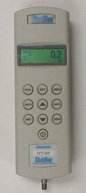
8 About the Keypad The DFT/CD2 keypad consists of ten dedicated keys (PEAK, EXIT, MENU, UNITS, SAVE, XMIT, ZERO, ON/OFF, UP ARROW, DOWN ARROW). When an active key is pressed, the gauge transmits an audible BEEP. Correspondingly, when an inactive keypad is pressed, the gauge makes no sound. MENU key moves you through the configuration process and is used to select operating options. Selecting the MENU key will invoke the current option that is displayed by the gauge. When a new option is accepted, the option flashes three times. The display will then move to the next configurable option. EXIT key moves you back to the main display screen. PEAK key cycles through three different operating modes: capture of the Normal reading; Peak Compression reading; or Peak Tension reading. The selected mode is indicated in the upper left of the display screen. SAVE key stores current test data reading in memory. Up to 100 different data points may be retained in memory and downloaded via the gauge RS-232 port or Mitutoyo ouputs. UP/DOWN ARROW keys are used to select options within each setup display. They are also used to display stored data within the gauge memory while in Data Review Mode. UNITS key allows you to select the display reading in Pounds force (LB), Kilograms (KG) and Newtons (N). This setting is indicated in the lower right of the main display screen. XMIT key transmits the displayed value from an individual test or all test data stored in memory via the gauge RS-232 port or Mitutoyo output. ZERO key returns current display to zero reading. ON/OFF Turns power to the gauge ON or OFF About the Display The DFT/CD2 series display is an LCD dot matrix display. As different keys are pressed, the display adjusts accordingly. The display illustrates different symbols such as: battery symbol indicating the battery is running low; round circle represents that Auto-Shutdown has been activated; force being applied to the load cell is represented by a C for compression or a T for tension. The upper left corner of the display indicates the operational mode (NORM, T-PK or C-PK). The bottom right hand corner represents the measurement unit LB, KG, N. The display updates 4 times per second. -8-
9 NORMAL DISPLAY starts up after the gauge is turned on. Unit of measure setting (lower right) toggles through LB, KG, N by use of the UNITS key. Graphic indicator shows portion of battery charge remaining (if the battery is low) and the time remaining until auto shutdown. Pressing the MENU key cycles the display through nine different menu options, allowing the user to adjust gauge settings as shown in Figure 1.2. Settings are adjusted by using the UP and DOWN ARROW keys. Use the EXIT key to take the user back to normal start up screen. Figure 1.2 DFT/CD2 Menu -9-
10 1.3. RECHARGING BATTERIES A rechargeable NiCad battery powers the DFT/CD2 Series. Since the NiCad batteries continue to discharge when not in use, it may be necessary to recharge the unit before use. When the battery power begins to lose its charge, the Battery Indicator will appear on the display. As the battery loses its charge, the dark filling in the indicator slowly disappears. When the indicator is no longer filled, the gauge will automatically shutdown. To recharge the battery, plug the battery charger included with the gauge into the correct voltage source and insert the charger jack into the receptacle on the end of the gauge. Charge the battery for hours to yield approximately 8-10 hours of continuous operation. The gauge can be operated continuously with the battery charger connected to the gauge. Note: Before using the gauge, please fully charge the NiCad battery pack. Use only the battery charger supplied with the gauge. Using other chargers can overcharge and damage the battery CONNECTING TO EXTERNAL DEVICES The DFT/CD2 Series can be configured to accept input from an external source, and/or to send output to an external data-recording device, such as a strip chart recorder, an RS-232 or Mitutoyo printer, or a personal computer. It can be used in combination with CHATILLON test stands and application software such as NEXYGEN to meet a wide variety of application requirements. To connect the gauge to a device, attach the appropriate interface cable to the port located on the end of the gauge and the other end to the external device REVERSING THE HOUSING The DFT/CD2 Series is shipped shaft down for test stand mounted applications, and the display on the front of the gauge is configured accordingly. For performing operations in which the gauge will be hand held it may be desirable to rotate the front housing so that the display and logo will be viewed right side up. To perform this procedure, remove the two screws from the back of the gauge, carefully rotate the front housing 180 degrees being careful not to pull, pinch or twist the wires inside, and then reinstall the screws. NOTE: When removing the screws to the back housing, please utilize proper ESD (Electro Static Discharge) precautions. Touching the printed circuit board without taking the proper ESD precautions may cause damage to the printed circuit board. -10-
11 1.6. SETTING UP FOR SAFE USE The DFT/CD2 Series should be properly setup before accurate and most of all, safe measurement can be made. Only when you verified that you will be conducting a safe test, proceed as follows: Determine how the sample will be tested and verify that the DFT/CD2 Series can handle the test. If desired, mount the gauge to the test fixture. If you will be powering the instrument from the AC line, plug the charger into its jack on the instrument. Plug the charger into the correct AC voltage outlet (the required AC voltage, current and frequency are listed on the charger). If powering the gauge from batteries, fully charge the batteries before using. Attach all necessary attachments and plug in cables if applicable. Route the cables so that they do not interfere with the test. Attach the specimen, zero the gauge by pressing the ZERO key, and begin to take measurements. -11-
12 2. FRONT PANEL OPERATION The DFT/CD2 Series can operate in one of three test modes: Normal, Data save and Configuration NORMAL MODE The principle function of the Normal Mode is to provide indications of load applied to the load cell. Instantaneous force, peak-tension and peakcompression readings can be displayed and scaled in a variety of units of measure Selecting type of Measurement Capturing Peaks The gauge continuously measures instantaneous tension or compression forces (often called normal readings). It also captures peak-tension and peak-compression forces. Pressing the PEAK key will cycle between Normal, Tension-Peak, and Compression-Peak measurements. The upper left corner of the display will indicate NORM, T-PK, C-PK, respectively Selecting Units of Measure Force indications can be displayed in LB, KG, or N. The gauge displays the active units of measure in the lower right corner of the LCD display. Pressing the UNITS key will cycle between the three available measuring units Zeroing Zeroing allows you to exclude the weight of accessories and attachments from the indicated force readings. It also clears captured peak tension and compression readings. To zero the gauge, momentarily press the ZERO key. Only the current measurement type (i.e., NORM, T-PK, C-PK) will be zeroed. To zero and clear all measurement types press and hold the PEAK key and then press the ZERO key Transmitting Readings Pressing the XMIT key will cause the gauge to transmit a single reading (current measurement type and current units) through the output port (Mitutoyo or RS-232). If the gauge is in NORM mode, the data value (NORM, T-PK or C-PK) displayed on the screen will be transmitted. If the gauge is in the Data Review Mode, then all of the stored values will be transmitted DATA SAVE MODE The Data Save Mode permits the operator to store up to 100 data sets acquired during tests. Each data set consists of 2 items: (1) sample number and (2) tension peak value, compression peak value or indicated instantaneous force with unit of measure. The total number of data sets is limited to 100. Data is stored in a nonvolatile memory and is retained even if the gauge is turned off or the battery pack is removed. Stored data sets can be reviewed (displayed), printed, or uploaded to a personal computer. -12-
13 Storing Readings While in Normal Mode, press the SAVE key to enter the Data Save Mode. The gauge operates just like in the Normal Mode except that additional information is shown on the display. The PEAK key selects the type of measurement being displayed, e.g. instantaneous force, peak-tension, or peak-compression force, and the UNITS key is used to select the unit of measure. The ZERO and ZERO-PEAK keys zero the current reading or all readings, respectively. The XMIT key causes the gauge to send the current reading through the output port. The top line of the display shows #YYY which indicates the data set number where the next data set will be stored, e.g. #003 means the next stored value will represent the third sample. The bottom line shows the percentage of data memory used. When 100% is indicated, the memory is full and no more data can be stored until the memory is cleared. In the Data Save Mode (not Data Review Mode), the gauge will display the word FULL where the YYY is displayed when memory is 100% full. To save the current reading, momentarily press the SAVE key. A complete data set is stored and the data set index is incremented. To save another data set, simply press the SAVE key again. All saved data sets can be reviewed by pressing the UP ARROW key to invoke the Data Review screen. Note that the Data Review screen cannot be invoked if there is no data stored. To clear memory (and erase ALL saved data) press and hold the ZERO key and then press the SAVE key Reviewing and Printing Stored Readings To enter the Data Review screen, press the UP ARROW key from the Data Save Mode. The gauge displays the most recent displayed measurements. The top line of the display shows #YYY which represents the last data set stored. The second line shows the data value stored, which may be either the NORM, T-PK, C-PK value indicated in the upper left corner of the display. The third line shows the percentage of memory used and the units of measure of the stored value. Press XMIT key to send all data sets to the output port using the currently selected print format. See Section for data/print details. Use the UP ARROW or DOWN ARROW keys to select data sets. Press the EXIT or SAVE key to return to the Data Save Mode. Note that the Data Review display cannot be invoked if there is no data stored. -13-
14 2.3. CONFIGURATION MODE The Configuration Mode facilitates setup, configuration and the customizing of the DFT/CD2 Series to satisfy varying needs of users. See Section 4.2 Menu Structures Configuring Output Port The output port of the DFT/CD2 Series supports RS-232 Serial Port and Mitutoyo Port standards for easy interfacing to printers, personal computers, and Mitutoyo devices. Before a connection between the gauge and an external device can be established, the output port must be properly configured. First a proper communication standard must be selected. From the Normal mode screen, press the MENU key. The COMM DEVICE: selection screen will display either RS-232 or MITUTOYO, indicating the current output port configuration Enabling the MITUTOYO Output To enable the MITUTOYO standard, press the MENU key from the Normal Mode display. If MITUTOYO is displayed, the MITUTOYO output is already enabled. Press the MENU key to advance the gauge to the next display, which is AUTO SHUTDOWN. If RS-232 is displayed after depressing the MENU key from the Normal Mode display, then you will need to change to the MITUTOYO output. Press the UP or DOWN ARROW key until MITUTOYO is displayed and then press the MENU key. The word MITUTOYO will flash three times, signifying that the enabling process is complete. The screen will next display AUTO SHUTDOWN. Press EXIT key at any time to return to Normal Mode. Proceed to Section for information in the MITUTOYO print format. NOTE: When a Mitutoyo printer is attached to the gauge and the gauge is powered ON or OFF, the following will print *NO DATA* Enabling and Configuring the RS-232 Port To enable the RS-232 Serial Port standard or to further configure the port, press the MENU key from the Normal Mode display. If RS-232 is displayed, then this option is already enabled. Press the MENU key to advance to the next display PRINT FORMAT. If MITUTOYO is displayed, the Mitutoyo output option is enabled and must be changed. To enable the RS-232 standard, press the UP or DOWN ARROW key until RS-232 is displayed and then press the MENU key. The word RS-232 will flash three times, signifying that the enabling process is complete. The screen will next display PRINT FORMAT. Press EXIT at any time to return to the Normal Mode. Once RS-232 has been selected, the gauge will advance and guide you through the PRINT FORMAT setup (Section 2.3.2), and the -14-
15 configuration settings of Baud Rate, Transmit Units, Length/Stop Bits and Parity. Press EXIT to return to the Normal Mode Configuring RS-232 Transmit Units The readings transmitted via the RS-232 port of the DFT/CD2 Series can be appended with the unit of measure information. After the PRINT FORMAT is selected, the TRANSMIT selection display appears showing the current stored selection that is either W/ UNITS or W/O UNITS. Press the UP or DOWN ARROW key to toggle between the two selections. Press the MENU key to accept the TRANSMIT selection and advance to the next configuration step. If the selection was changed, the new selection will flash three times to indicate that the new selection has been applied. If the selection did not change from the original setting, the gauge will advance to the next configuration step without flashing. Press EXIT key to return to the Normal Mode display Configuring RS-232 Baud Rate The RS-232 transmitter/receiver of the DFT/CD2 Series can be configured to operate at 300, 600, 1200, 2400, 4800, 9600, 19,200, 28,800, 38,400, 57,600, 115,200 Baud. After the TRANSMIT UNITS selection is chosen, the BAUD RATE selection is displayed indicating the current selected baud rate. Press the UP or DOWN ARROW key to toggle through the different baud rate selections. Press the MENU key to accept the desired baud rate. If the baud rate is different from the originally stored baud rate, the new baud rate will flash three times indicating the new baud rate has been applied. If the baud rate is not changed, the gauge will advance to the next configuration step without flashing. Press EXIT to return to the Normal Mode display Configuring RS-232 Word Length The RS-232 transmitter/receiver of the DFT/CD2 Series can be configured for 8/1 (8 data bits, 1 stop bit) or 7/2 (7 data bits, 2 stop bits) operation. After the BAUD RATE configuration step, the LENGTH/STOP BITS display appears with the currently configured length/stop bits. Press the UP or DOWN ARROW key to toggle between the two selections. Press MENU key to accept desired word length. If the word length format has changed, the new format will flash three times, indicating the new word length has been applied. If the word length format did not change, the gauge will advance to the next configuration step without flashing. Press EXIT key to return to the Normal Mode display Configuring RS-232 Parity The RS-232 transmitter/receiver of the DFT/CD2 Series can be configured for EVEN or NONE parity. After the WORD LENGTH configuration, the gauge will display the currently configured parity of the gauge. Press the UP or DOWN ARROW key to toggle between the two selections. Press the MENU key to select the desired parity. If the parity format has changed, the new format will -15-
16 flash three times, indicating the new parity has been applied. If the parity format did not change, the gauge will advance to the next configuration step without flashing. Press EXIT key to return to the Normal Mode display. Note: When word length 7/2 and parity EVEN are both selected, the RS-232 transmitter/receiver is configured for 7 data bits, 1 stop bit and even parity Formatting Stored Data Printouts The DFT/CD2 Series supports 1 COLUMN or 2 COLUMN format for data printing with RS-232. MITUTOYO printing always uses the 1 COLUMN format. 1 COLUMN FORMAT: This option prints one force value per line. MITUTOYO Output RS-232 Output LB T-PK LB Norm 2 COLUMN FORMAT: This option prints the sample number and force value on each line. Sample Data LB T-PK LB Norm To invoke the print format screen (PRINT FORMAT:) press the MENU key followed by the selection of RS-232 in the COMMUNICATION DEVICE selection display. The PRINT FORMAT selection screen will display the current stored PRINT FORMAT. Press the UP or DOWN ARROW key to toggle between the two selections. Press MENU key to accept desired print format. If the print format has changed, the new format will flash three times, indicating the new print format has been applied. If the print format did not change, the gauge will advance to the next configuration step without flashing. Press EXIT key to return to the Normal Mode display Configuring AUTO SHUTDOWN If enabled, the AUTO SHUTDOWN feature will turn off the DFT/CD2 Series after 10 minutes of inactivity. Inactivity is defined by no keypad presses, no commands received from the output port, and no significant change in applied force. This feature may be disabled. -16-
17 To invoke the AUTO SHUTDOWN feature, continue to press the MENU key until the gauge displays AUTO SHUTDOWN. You can activate the AUTO SHUTDOWN feature by using the UP OR DOWN ARROW key to select either ON or OFF. Once On is displayed press MENU key and the AUTO SHUTDOWN feature is now activated. To disable this feature, select the OFF and press MENU key and the feature will be disabled. If the auto shutdown format has changed, the new format will flash three times, indicating the new auto shutdown format has been applied. If the auto shutdown did not change, the gauge will advance to the next configuration step without flashing. Press EXIT key to return to the Normal Mode display Adjusting the Display Contrast The graphical LCD display of the DFT/CD2 Series may have to be adjusted to provide the best contrast for the viewing angle and ambient temperature. To invoke the display contrast adjustment screen (CONTRAST:) continue to press the MENU key until CONTRAST display appears. The CONTRAST screen will display both LIGHTER and DARKER. Press the UP or DOWN ARROW key to change the display contrast. Press the MENU key to accept the desired contrast. The gauge will then advance to the SERVICE selection menu. Press EXIT key to return to the Normal Mode display Performing the Self Test In the Self Test Mode, the DFT/CD2 Series performs a series of selfdiagnostic tests. The Self Test menu displays facts about the gauge settings and allows the operator to verify that the keys are working properly. The SELF TEST is accessed by pressing the MENU key until the SERVICE menu is displayed and CONTINUE is displayed. Scroll through the menu by pressing the UP or DOWN ARROW key until SELF-TEST is displayed. Press the MENU key to accept and place the gauge into the self-test operation. Press the EXIT key during any step (except for the Keypad Test) to return the gauge to the previous SELF-TEST menu selection. The KEYPAD Test (the last part of the Self-Test) may only be exited by pressing the ON/OFF key. The following are the seven Self-Test steps and their functions: SOFTWARE VERSION SOFTWARE REVISION CAPACITY: The capacity of the gauge is displayed in the unit of measurement that has been selected (i.e., LB, KG, N). % FULL SCALE : Indicates the force being applied to the gauge as a percentage of full scale. This percentage is measured relative to the COMPRESSION NO LOAD force that was present when the gauge was last calibrated (Section Step 9). PLACE GAUGE HORIZONTALLY: Indicates to the operator to place the gauge horizontally. -17-
18 ZERO LOAD: PASS or FAIL will show on the display. If PASS is indicated, then proceed to next step. If fail is the result, the load cell may be damaged and you will need to contact your local distributor, as the gauge may need to be serviced. KEYPAD TEST: When a key is pressed, except for the ON/OFF key, the display indicates the key s function. The only way to exit this screen is to press the ON/OFF key, which will turn OFF the gauge Calibrating the DFT/CD2 Series The DFT/CD2 Series has a built-in calibration procedure that permits verification and adjustments to the gauge without returning it to the factory. The following additional requirements are needed: You must have a way to mount the gauge vertically in both tension and compression directions. The DFT/CD2 Series will permit calibration using deadweights representing 100% of the rated full scale with 20% increments. For example, calibrating a 10 LB gauge, the deadweights must be in 20% increments for a total of 10 LB at the correct local gravity. The calibration process is invoked from the Normal Mode by pressing the MENU key until the SERVICE menu appears and CONTINUE is displayed. Scroll through the menu by pressing the UP or DOWN ARROW key until CALIBRATE is displayed. Press the MENU key to accept Calibration Mode. The gauge will display PRESS MENU TO BEGIN. Press MENU and proceed to Section DFT/CD2 Series Calibration Steps 1 16 This section leads you step by step through the calibration process. Note: The DFT/CD2 Series will not advance if an error has occurred during the calibration process. The gauge will display one of two possible error messages. The first message (NOT STABLE) may be displayed due to excessive vibration. The second message (OUT OF RANGE) is displayed when the gauge detects a nominal error of 20%. Pressing the ON/OFF key during any phase of the calibration process will cause the gauge to discard any new calibration information. Step 1 The display prompts you to SELECT UNITS TO CALIBRATE. Press the UP or DOWN ARROW key to cycle through the available units of measure. Press the MENU key to accept the selected units of measure, or press the EXIT key to return to the Normal Mode. Step 2 The display prompts you to SELECT CAPACITY. Press the UP or DOWN ARROW key to cycle through available capacities. Press the MENU key to accept the displayed capacity and to proceed on to the next step. Press the EXIT key to return to the previous calibration step. -18-
19 Predefined capacities depend on the units of measure selected: LB: 2, 10, 50, 100, 200, 500 KG: 1, 5, 20, 50, 100, 200 N: 10, 50, 200, 500, 1000, 2000 Step 3 The display prompts you to PLACE GAUGE IN HORIZONTAL POSITION. After doing so, press the MENU key to proceed to the next step (the gauge displays ZEROING ) or press EXIT to return to the previous calibration step. Step 4 The display prompts you to ADD FULL SCALE COMPRESSION LOAD. Add full scale compression load to the gauge and exercise the load cell three times. Stabilize the weight. Press MENU key to proceed. The gauge will display CALIBRATING and the gauge will proceed to the next step. Otherwise, press the EXIT key to return to the previous calibration step. Step 5 The display prompts you to ADD 80% FULL SCALE COMPRESSION LOAD. Apply 80% of full scale compression load to the gauge and stabilize the weight. Press MENU key to proceed. The gauge will display CALIBRATING and the gauge will proceed to the next step. Otherwise, press the EXIT key to return to ADD FULL SCALE COMPRESSION LOAD. Step 6 The display prompts you to ADD 60% FULL SCALE COMPRESSION LOAD. Apply 60% of full scale compression load to the gauge and stabilize the weight. Press MENU key to proceed. The gauge will display CALIBRATING and the gauge will proceed to the next step. Otherwise, press the EXIT key to return to ADD FULL SCALE COMPRESSION LOAD. Step 7 The display prompts you to ADD 40% FULL SCALE COMPRESSION LOAD. Apply 40% of full scale compression load to the gauge and stabilize the weight. Press MENU key to proceed. The gauge will display CALIBRATING and the gauge will proceed to the next step. Otherwise, press the EXIT key to return to ADD FULL SCALE COMPRESSION LOAD. Step 8 The display prompts you to ADD 20% FULL SCALE COMPRESSION LOAD. Apply 20% of full scale compression load to the gauge and stabilize the weight. Press MENU key to proceed. The gauge will display CALIBRATING and the gauge will proceed to the next step. Otherwise, press the EXIT key to return to ADD FULL SCALE COMPRESSION LOAD. Step 9 The display prompts you to SETUP GAUGE COMPRESSION NO LOAD. Remove all weight from gauge, leaving fixtures attached to gauge and press MENU key to proceed. The gauge will display CALIBRATING and the gauge will proceed to the next step. -19-
20 Otherwise, press the EXIT key to return to ADD FULL SCALE COMPRESSION LOAD. Step 10 The display prompts you to ADD FULL SCALE TENSION LOAD. Add full scale tension load to the gauge and exercise the load cell three times. Stabilize the weight. Press MENU key to proceed. The gauge will display CALIBRATING and the gauge will proceed to the next step. Otherwise, press the EXIT key to return to ADD FULL SCALE COMPRESSION LOAD. Step 11 The display prompts you to ADD 80% FULL SCALE TENSION LOAD. Apply 80% of full scale tension load to the gauge and stabilize the weight. Press MENU key to proceed. The gauge will display CALIBRATING and the gauge will proceed to the next step. Otherwise, press the EXIT key to return to ADD FULL SCALE TENSION LOAD. Step 12 The display prompts you to ADD 60% FULL SCALE TENSION LOAD. Apply 60% of full scale tension load to the gauge and stabilize the weight. Press MENU key to proceed. The gauge will display CALIBRATING and the gauge will proceed to the next step. Otherwise, press the EXIT key to return to ADD FULL SCALE TENSION LOAD. Step 13 The display prompts you to ADD 40% FULL SCALE TENSION LOAD. Apply 40% of full scale tension load to the gauge and stabilize the weight. Press MENU key to proceed. The gauge will display CALIBRATING and the gauge will proceed to the next step. Otherwise, press the EXIT key to return to ADD FULL SCALE TENSION LOAD. Step 14 The display prompts you to ADD 20% FULL SCALE TENSION LOAD. Apply 20% of full scale tension load to the gauge and stabilize the weight. Press MENU key to proceed. The gauge will display CALIBRATING and the gauge will proceed to the next step. Otherwise, press the EXIT key to return to ADD FULL SCALE TENSION LOAD. Step 15 The display prompts you to SETUP TENSION NO LOAD. Remove all weight from gauge, leaving fixtures attached to gauge and press MENU key to proceed. The gauge will display CALIBRATING and the gauge will proceed to the next step. Otherwise, press the EXIT key to return to ADD FULL SCALE TENSION LOAD. Step 16 If the calibration was successful, the display indicates TO SAVE NEW CALIBRATION PRESS MENU. Press MENU to save the new calibration and return to the Normal Mode, or press the EXIT key to return to ADD FULL SCALE TENSION LOAD. -20-
21 3. REMOTE OPERATION AND SETUP The DFT/CD2 Series can accept and execute commands through the RS-232 serial port. The command set is tailored to make it easy to configure and operate the instrument under computer control. The string commands are sent as strings of ASCII characters. The following string commands are recognized: Command Response Description Legend: ^ is space (20 hex); 9 is a number 0 through 9; ± is a space or a minus <CR> is Carriage Return (0D hex); <LF> is Line Feed (0A hex). ^^^^^^^^^^<CR><LF> On power-up, this line is sent A Unit^=lb^<CR><LF> or Sends currently selected Unit^=kg^<CR><LF> or units Unit^=N^^<CR><LF> F P R Toggles between Data Collect and the Normal and Peak Modes Steps through Normal and Peak Modes: Normal, Tension Peak, Compression Peak Resets the gauge: zeroes all modes S ^N-MODE^^^<CR><LF> or Sends currently selected TP-MODE^^^<CR><LF> or mode: Normal, Tension Peak, CP-MODE^^^<CR><LF> or Compression Peak and Data DC-MODE^^^<CR><LF> Collect U Steps through Units in the following order: lb, kg, N Table 3.1 Remote Operation and Setup Commands -21-
22 Command Response Description X or? ±99.999^lb<CR><LF> or Sends data on display with ±9999.9^kg<CR><LF> or the position of the decimal ±99.999^N^<CR><LF> place the same as on display. If in Data collect Mode, sends data from the Data Collect filter instead. If "Transmit Units" is set to transmit without units, lb, kg, and N are replaced by ^^. ERROR^^^^^<CR><LF> Response during force overload Y Y204 to Y211 Begins sending instantaneous, Tension Peak, Compression Peak or Data Collect data from 100 times per second to once every 2 seconds. Z Zeroes the currently selected mode: Normal, Tension Peak or Compression Peak. Table 3.1 Remote Operation and Setup Commands -22-
23 4. TECHNICAL REFERENCE 4.1. SPECIFICATIONS Accuracy: ±0.15% of Full Scale ±1 LSC Tare capacity: 10% of Full Scale. A tare value of greater than 10% can be used, however the full range of the gauge capacity may not be reached. Deflection: 0.01 inch maximum at full load. Safe Overload: Gauge will display OVERLOAD when the force applied exceeds 116% of the gauge capacity. Overload: Maximum overload is 150% of full scale capacity. Load Cell deformation may occur when overload exceeds 150% of full scale capacity. Contact your local AMETEK distributor if you experienced and overload exceeding 150% of full scale capacity. Temperature Range: 40 to 110 F (5 to 45 C) Temperature Stability: 0.06% per F Analog Output: -2.0 to +2.0VDC ±0.018VDC Digital Output: RS-232 and MITUTOYO Firmware Revision Control: Capability to download future revisions of firmware using software upgrade kit. Display Update: Four samples per second (250ms refresh) in Normal or Peak Mode. Data Collect Mode: 200 samples per second Data Storage: Stores up to 100 data samples per second Sampling Rate: 1,000 samples per second Battery Charge Life: 8-10 hours of continuous operation when fully charged. -23-
24 4.2. MENU STRUCTURE MENU COMM DEVICE RS-232 MITUTOYO PRINT FORMAT 1 Column 2 Column TRANSMIT W/ Units W/O Units BAUD RATE 300/600/1200/ /9600/19.2K 28.8K/38.4K/57.6K 115.2K WORD LENGTH/STOP BITS 8/1 7/2 PARITY NONE EVEN AUTO SHUTDOWN ON OFF CONTRAST LIGHTER DARKER SERVICE CONTINUE CALIBRATE SELF-TEST -24-
25 4.3. OUTPUT PORT SPECIFICATIONS Figure 4.3 I/O Connector (On Gauge) (View from Solder End) The DFT/CD2 Series is supplied with a 12-pin female connector on the gauge to provide both digital and analog outputs. AMETEK offers a variety of cables to handle most applications (Refer to Section 4.5.4). Select the cable type required to connect the DFT/CD2 Series gauge to the peripheral device. The pin out of the connector is shown in Figure 4.3. Pin assignments are defined in Table 4.3. Pin Symbol I/O Purpose Description 1 TXD O RS-232 Transmitted Data 2 RXD I RS-232 Received Data 3 GND - Ground Digital Ground 4 O Clock Mitutoyo Clock 5 O Ready Mitutoyo Ready 6 I Request Mitutoyo Request 7 O Data Mitutoyo Data 8 I (Reserved) 9 O (Reserved) 10 GND - Ground Digital Ground 11 - Analog GND Analog Ground 12 O Analog SIG Analog Output Table 4.3 I/O Connector Pinout -25-
26 4.4. DEFAULT SETTINGS The DFT/CD2 Series gauges come configured with the following default settings from the factory. Mode: Normal Units of Measure: LB Communication: Device: RS-232 Print Format: 1 Column Transmit Units: W/ Units Baud Rate 9600 Length/Stop Bits: 8/1 Parity: None Auto Shutdown: On 4.5. ACCESSORIES, SPARE PARTS, MOUNTING KITS & CABLES Accessories Accessory Part DFT/CD2 Number Carrying Case, DFT SPK-DFT Carrying Case, CD2 SPK-CD Battery Charger 110V 1 SPK-FMG-069A Battery Charger 220V 1 SPK-FMG-069B Shaft Adapter SPK-DFT-068A Shaft Adapter SPK-DFT-068B Hook SPK-FMG-012A Hook & Coupling Assy SPK-FMG-012B Hook & Coupling Assy SPK-FMG-012C Flat Adapter SPK-FMG-011A Flat Adapter SPK-FMG-011B Chisel Adapter SPK-FMG-008A Chisel Adapter SPK-FMG-008B Point Adapter SPK-FMG-009A Point Adapter SPK-FMG-009B Notch Adapter SPK-FMG-010A Notch Adapter SPK-FMG-010B Extension Rod SPK-FMG-013A Extension Rod SPK-FMG-013B Hex Key SPK-FMG Operator Manual SPK-DFT Quick Reference Guide NC Note: 1 A Battery Charger is provided standard with your DFT/CD2 Series gauge. The voltage type depends on the type of gauge specified. -26-
27 Spare Parts Accessory Part DFT/CD2 Number Load Cell Assy, 2 LB SPK-DFT-065A Load Cell Assy, 10 LB SPK-DFT-065B Load Cell Assy, 50 LB SPK-DFT-065C Load Cell Assy, 100 LB SPK-DFT-065D Load Cell Assy, 200 LB SPK-DFT-065E Load Cell Assy, 500 LB SPK-DFT-065F Battery Pack Assy SPK-DFT Keypad, DFT SPK-DFT Keypad, CD2 SPK-CD PC Board Assy SPK-DFT Lens NC Bottom Case Assy, DFT SPK-DFT Bottom Case Assy, CD2 SPK-CD Power Jack Cable Assy SPK-FMG Pin Cable Assy SPK-FMG Mounting Kits Test Stand Model 2-Hole 100 LB or Less 4- Hole 200 LB LTS See Note 1 N/A LTC See Note 1 N/A HTC HTCK-2 2 N/A TCM 201 SPK-FM SPK-FM TCD 200 SPK-FM SPK-FM LF Plus SPK/LFM/ SPK/LFM/ Notes: 1. Must remove Dowel Pin P/N 3256 from gauge adapter. 2. Must remove Dowel Pin P/N 3256 from HTCK-2 plate. 3. Included with test stand. 4. Adapter will come with test stand if specified when ordering LF Plus. -27-
28 Cables Cable NC NC NC NC ENC0125 NC Description Connects DFT/CD2 Series Gauge to a personal computer with a 9-pin RS-232 connection Connects DFT/CD2 Series Gauge to a personal computer with a 25-pin RS-232 connection Connects DFT/CD2 Series Gauge to a Mitutoyo device with a 10-pin connection Connects DFT/CD2 Series Gauge to Chatillon model TCD Test Stand Connects DFT/CD2 Series Gauge to Chatillon Model TCM201 Test Stand Connects DFT/CD2 Series Gauge to X-Y Recorder using a dual banana jack plug 4.6. FIRMWARE UPGRADES The DFT/CD2 Series gauges feature a flash memory to facilitate field upgrades of the instrument firmware. Upgrade kits will be offered by AMETEK as new features are added to the instrument. The downloading of firmware from the upgrade kits will require the DFT/CD2 Series gauge to be connected to a personal computer. The DFT/CD2 series firmware upgrade kit part number is E
29 5. PRODUCT WARRANTY This instrument is warranted against defects in workmanship, material and design for one (1) year from date of delivery to the extent that AMETEK will, at its sole option, repair or replace the instrument or any part thereof which is defective, provided, however, that this warranty shall not apply to instruments subjected to tampering or abuse, or exposed to highly corrosive conditions. THIS WARRANTY IS IN LIEU OF ALL OTHER WARRANTIES WHETHER EXPRESS OR IMPLIED AND AMETEK HEREBY DISCLAIMS ALL OTHER WARRANTIES, INCLUDING, WITHOUT LIMITATION, ANY WARRANTY OF FITNESS FOR A PARTICULAR PURPOSE OR MERCHANTABILITY. AMETEK SHALL NOT BE LIABLE FOR ANY INCIDENTAL OR CONSEQUENTIAL DAMAGES INCLUDING, BUT NOT LIMITED TO, ANY ANTICIPATED OR LOSS PROFITS. This warranty is voidable if the purchaser fails to follow any and all instructions, warnings, and cautions in the instrument s Instruction Manual. If a manufacturing defect is found, AMETEK will replace or repair the instrument or replace any defective part thereof without charge; however, AMETEK s obligation hereunder does not include the cost of transportation which must be borne by the customer. AMETEK assumes no responsibility for damage in transit, and any claims for such damage should be presented to the carrier by the purchaser. -29-
30 ISO 9001 Manufacturer Americas Asia Pacific AMETEK TCI Division AMETEK Lloyd Instruments 8600 Somerset Drive N0. 7 Sherwood Place Largo, Florida Alexander Heights USA 6064 Perth Tel Australia Tel (USA only) Tel Fax Fax United Kingdom Singapore AMETEK Lloyd Instruments Ltd. AMETEK Singapore Pvt. Ltd. Forum House 10 Ang Mo Kio Street Barnes Wallis Road #05-12 TECHPOINT Segensworth East Singapore Fareham Hampshire PO 15 5TT Tel Tel +44(0) Fax Fax +44(0) France Germany AMETEK Lloyd Instruments SA AMETEK Precision Instruments 3 Avenue des Coudriers Europe GmbH Zone d Activite de l Observatoire Rudolf-Diesel-Strasse Montigny-Le-Bretonneux D-40670, Meerbusch France Germany Tel Tel Fax Fax Internet Addresses: AMETEK and CHATILLON are registered trademarks of AMETEK, Inc. LLOYD INTRUMENTS is an AMETEK Inc. trademark. Information within this document is subject to change without notice. Pub No. NC Issued 05/2002 Copyright 2002, by AMETEK, Inc. Printed in U.S.A. -30-
Artisan Technology Group is your source for quality new and certified-used/pre-owned equipment
 Artisan Technology Group is your source for quality new and certified-used/pre-owned equipment FAST SHIPPING AND DELIVERY TENS OF THOUSANDS OF IN-STOCK ITEMS EQUIPMENT DEMOS HUNDREDS OF MANUFACTURERS SUPPORTED
DFE Series Digital Force Gauge
 DFE Series Digital Force Gauge The CHATILLON DFE Series marks a new era in digital force measurement. This compact, easy-to-use force gauge is designed for economy applications without compromising functionality.
FG-7000 Digital Force Gauge Operation Manual
 FG-7000 Digital Force Gauge Operation Manual Operators should wear protection such as a mask and gloves in case pieces or components break away from the unit under test. Whether the unit is ON or OFF,
Model ST-FT1 DIGITAL FORCE / TORQUE INDICATOR. User s Guide
 Model ST-FT1 DIGITAL FORCE / TORQUE INDICATOR Thank you Thank you for purchasing a Mesa Labs Model ST-FT1 digital force / torque indicator, designed for use with a remote torque sensor. With proper usage,
DF II Series Digital Force Gauges for DFS II, DFS II-R, DFS II-R-ND and DFE II Models. User Manual. DF II Series User Manual 1
 Part No. NC003194 July 2013 DF II Series Digital Force Gauges for DFS II, DFS II-R, DFS II-R-ND and DFE II Models User Manual DF II Series User Manual 1 WARRANTY This instrument is warranted against defects
Series CTA CAP TORQUE TESTERS. User s Guide
 Series CTA CAP TORQUE TESTERS User s Guide Series CTA Cap Torque Testers Thank you! Thank you for purchasing a Mark-10 Series CTA Cap Torque Tester. We are confident that you will get many years of service
Series ST. User s Guide DIGITAL TORQUE TOOL TESTERS. .com. Series ST Torque Tool Testers. User s Guide
 Series ST DIGITAL TORQUE TOOL TESTERS.com Mark-10 Corporation has been an innovator in the force and torque measurement fields since 1979. We strive to achieve 100% customer satisfaction through excellence
Series STA DIGITAL TORQUE TOOL TESTERS. User s Guide
 Series STA DIGITAL TORQUE TOOL TESTERS User s Guide Series STA Torque Tool Testers Thank you! Thank you for purchasing a Mark-10 Series STA Digital Torque Tool Tester. We are confident that you will get
User s Guide. Series CT CLOSURE TORQUE TESTER. User s Guide
 User s Guide Series CT CLOSURE TORQUE TESTER User s Guide Series CT Closure Torque Testers User s Guide Thank you! Thank you for purchasing a Mark-10 Series CT Torque Tester. We are confident that you
DFS Series User s Manual (5N-1000N Capacity)
") DFS Series User s Manual (5N-1000N Capacity) REV 3.8 Table of Contents Table of Contents 2 Introduction 3 Before Use 3 Operation Overview 4 Powering the DFS 5 Using the DFS. 6 Fitting Accessories 6 Mounting
DFS Series User s Manual (5N-1000N Capacity) REV 3.8 Table of Contents Table of Contents 2 Introduction 3 Before Use 3 Operation Overview 4 Powering the DFS 5 Using the DFS. 6 Fitting Accessories 6 Mounting
NEXYGEN MT v4.5. Materials Testing Software
 NEXYGEN MT v4.5 Materials Testing Software MATERIALS TESTING SOFTWARE NEXYGEN MT software provides a virtual testing laboratory. The software offers a full compliment of testing categories with multiple
DFS II Series. DFS II / DFS II-R / DFS II-R-ND Digital Force Gauge
 DFS II Series DFS II / DFS II-R / DFS II-R-ND Digital Force Gauge Functions and Features Easy-to-Read Display A large, easy-to-read full color LCD can display readings, icons and visually indicate gauge
Digital Measurement Metrology, Inc PRECISION IS OUR VISION
 Contents Powering the Gage 2 Using the Gage 3 Optional Settings 8 Dimensions 10 BFG Specification Table 11 Introduction Thank you for choosing the Mecmesin Corporation Basic Force Gage (BFG) instrument.
Digital Force Gauge INSTRUCTION MANUAL. Model: DS2
 2 YEAR WARRANTY (RESTRICTIONS APPLY) Imada, Inc. warrants its products to the original purchaser to be free from defects in workmanship and material under normal use and proper maintenance for two years
FG-3000 Digital Force Gauge Operation Manual
 FG-3000 Digital Force Gauge Operation Manual Operators should wear protection such as a mask and gloves in case pieces or components break away from the unit under test. Whether the unit is ON or OFF,
SHIMPO INSTRUMENTS. FG-7000T Digital Torque Gauge Operation Manual
 FG-7000T Digital Torque Gauge Operation Manual SHIMPO INSTRUMENTS Operators should wear protection such as a mask and gloves in case pieces or components break away from the unit under test. Whether the
User s Guide. Series 3 DIGITAL FORCE GAUGES
 Series 3 DIGITAL FORCE GAUGES Thank you Thank you for purchasing a Mark-10 Series 3 digital force gauge, designed for tension and compression force testing applications from 0.12 lbf to 500 lbf (0.5 N
User s Guide. Series 2 DIGITAL FORCE GAUGES
 Series 2 DIGITAL FORCE GAUGES Thank you Thank you for purchasing a Mark-10 Series 2 digital force gauge, designed for tension and compression force testing applications from 2 to 500 lbf (10 to 2,500 N)
DFS Series Digital Force Gauge With Integral Loadcell
 DFS Series Digital Force Gauge With Integral Loadcell he HAILLON DFS Series offers the best price performance of any digital force gauge available today. his compact, easy-to-use force gauge is designed
-Direct.com FG-3000 Digital Force Gauge Operation Manual
 FG-3000 Digital Force Gauge Operation Manual Operators should wear protection such as a mask and gloves in case pieces or components break away from the unit under test. Whether the unit is ON or OFF,
FG-7000L Digital Force Gauge Operation Manual
 FG-7000L Digital Force Gauge Operation Manual Operators should wear protection such as a mask and gloves in case pieces or components break away from the unit under test. Whether the unit is ON or OFF,
FG-3000R Digital Force Gauge Operation Manual
 FG-3000R Digital Force Gauge Operation Manual Operators should wear protection such as a mask and gloves in case pieces or components break away from the unit under test. Whether the unit is ON or OFF,
NIDEC-SHIMPO INSTRUMENTS
 Series FGE-HXY Force Gauges Operation Manual NIDEC-SHIMPO INSTRUMENTS Do not operate or store instrument in the following locations: Explosive areas, near water, oil, dust or chemicals; areas where the
NOTES TABLE OF CONTENTS
 NOTES TABLE OF CONTENTS 1.0 Introduction.................................................... 04 1.1 Standard Features 1.2 Accessories Included 2.0 Overview.....................................................
Series FGE-XY Force Gauges Operation Manual
 Series FGE-XY Force Gauges Operation Manual Do not operate or store instrument in the following locations: Explosive areas, near water, oil, dust or chemicals; areas where the temperatures can exceed 104
DTT Series Digital Torque Testers User Manual
 for DTT Models above Serial Number: 2000 15700 S. Waterloo Road Cleveland, OH 44110-3898 Phone: (888) 486-6163 Fax: (216) 481-4519 2017 Jergens, Inc. All Rights Reserved Revision Date: 02/19/18 Email:
NIDEC-SHIMPO INSTRUMENTS
 Series FGE-XY Force Gauges Operation Manual NIDEC-SHIMPO INSTRUMENTS Do not operate or store instrument in the following locations: Explosive areas, near water, oil, dust or chemicals; areas where the
TTC Series Torque Tool Tester Operation Manual
 TTC Series Torque Tool Tester Operation Manual Operators should wear protection such as a mask and gloves in case pieces or components break away from the unit under test. Whether the unit is ON or OFF,
DTT-L Series Digital Torque Testers User Manual
 15700 S. Waterloo Road Cleveland, OH 44110-3898 Phone: (888) 486-6163 Fax: (216) 481-4519 2017 Jergens, Inc. All Rights Reserved Revision Date: 02/19/18 Email: asginfo@asg-jergens.com Web: www.asg-jergens.com
AUTOMATION. Operator s Manual. PG5 Digital Pressure Gauge
 AUTOMATION P R O D U C T S GROUP, INC. Operator s Manual PG5 Digital Pressure Gauge DOC. 9003264 Rev. A1 3/10 Tel: 1/888/525-7300 Fax: 1/435/753-7490 www.apgsensors.com E-mail: sales@apgsensors.com PG5
HHTQ35 Digital Torque Gauges
 HHTQ35 Digital Torque Gauges 1 Thank you Thank you for purchasing an Omega HHTQ35 digital torque gauge, designed for handheld or test stand use. With proper usage, we are confident that you will get many
CC186 AND CC186/2 STAND-ALONE OR SYSTEM CLOCK
 FN:CC186M2.DOC CC186 AND CC186/2 STAND-ALONE OR SYSTEM CLOCK DESCRIPTION The CC186 is a single sided clock with six, 1.8 inch high digits. The CC186/2 is a double sided clock with six, 1.8 inch high digits
DFS Series Digital Force Gauge With Integral Loadcell
 DFS Series Digital Force Gauge With Integral Loadcell he HAILLON DFS Series offers the best price performance of any digital force gauge available today. his compact, easy-to-use force gauge is designed
Series E ERGONOMICS FORCE GAUGES. User s Guide
 Series E ERGONOMICS FORCE GAUGES Thank you Thank you for purchasing a Mark-10 Series E ergonomics force gauge, designed for tension and compression testing applications with a range of interchangeable
Digital Controllers Series DC MODEL DC4010 / ESMH-DC MODEL DC4020 / ESM-DC MODEL DC4030 / TSFM500-DC MODEL DC4040 / TSTM-DC.
 Digital Controllers Series DC MODEL DC4010 / ESMH-DC MODEL DC4020 / ESM-DC MODEL DC4030 / TSFM500-DC MODEL DC4040 / TSTM-DC User s Guide Series DC Digital Controllers Thank you! Thank you for purchasing
RV LEVELING SYSTEM AUTO LEVEL SYSTEM WARNING! FAILURE TO ACT IN ACCORDANCE WITH THE FOLLOWING MAY RESULT IN SERIOUS PERSONAL INJURY OR DEATH.
 RV LEVELING SYSTEM AUTO LEVEL SYSTEM WARNING! FAILURE TO ACT IN ACCORDANCE WITH THE FOLLOWING MAY RESULT IN SERIOUS PERSONAL INJURY OR DEATH. THE USE OF THE GROUND CONTROL AUTO LEVELING SYSTEM TO SUPPORT
AUTOMATION. Operator s Manual PG-5. Full Access. DOC Rev. A1 3/10
 AUTOMATION P R O D U C T S G R O U P, I N C. Operator s Manual PG-5 Full Access DOC. 9003384 Rev. A1 3/10 Tel: 1/888/525-7300 Fax: 1/435/753-7490 www.apgsensors.com E-mail: sales@apgsensors.com PG5 Rev.
Series 4. User s Guide DIGITAL FORCE GAUGES. Mobile: Fax:
 Series 4 DIGITAL FORCE GAUGES Office: Jl. Radin Inten II No. 62 Duren Sawit, Jakarta 13440 - Indonesia Workshop: Jl. Pahlawan Revolusi No. 22B, Jakarta 13430 - Indonesia Phone: 021-8690 6777 (Hunting)
Industrial RFID Reader
 Industrial RFID Reader User s Manual for the following models: FCC ID: IOL-125-AV1015 (6 Coil System) FCC ID: IOL-125-AV1016 (12 Coil System) FCC ID: IOL-125-AV1017 (24 Coil System) The device complies
User s Manual. Models Digital Force Gauge. Additional User Manual Translations available at
 User s Manual Models 475055 Digital Force Gauge Additional User Manual Translations available at www.extech.com Introduction Congratulations on your purchase of Extech s Model 475055 Digital Force Gauge
 PCE Americas Inc. PCE Instruments UK Ltd. 711 Commerce Way Units 12/13, Southpoint Business Park Suite 8 Ensign Way Jupiter, FL 33458 Hampshire / Southampton USA United Kingdom, SO31 4RF Phone: 561-320-9162
NIDEC-SHIMPO INSTRUMENTS
 TTR Torque Tool Tester Operation Manual NIDEC-SHIMPO INSTRUMENTS 1) Overloading the transducer does not only damage the transducer but may break the transducer head and could result in injury! 2) Torque
Digital Torque Tester
 YEAR WARRANTY (RESTRICTIONS APPLY) Imada, Inc. warrants its products to the original purchaser to be free from defects in workmanship and material under normal use and proper maintenance for two years
3 Input Multiplexer Operation Manual
 ProMUX-3 3 Input Multiplexer Operation Manual WARRANTY Accurate Technology, Inc. warrants the ProMUX-3 against defective parts and workmanship for 1 year commencing from the date of original purchase.
AD-8923-BCD. Remote Controller (BCD) INSTRUCTION MANUAL 1WMPD
 INSTRUCTION MANUAL 1WMPD") AD-8923-BCD Remote Controller (BCD) INSTRUCTION MANUAL 1WMPD4002137 2010 A&D Company, Limited. All rights reserved. No part of this publication may be reproduced, transmitted, transcribed, or translated
AD-8923-BCD Remote Controller (BCD) INSTRUCTION MANUAL 1WMPD4002137 2010 A&D Company, Limited. All rights reserved. No part of this publication may be reproduced, transmitted, transcribed, or translated
AWS-3000 Torque Display
 AWS-3000 Torque Display USER'S GUIDE February, 2008 AWS-5000 Shown with External Input Connector ADVANCED WITNESS SERIES, INC. 910 BERN COURT #100 SAN JOSE, CA 95112 (408) 453-5070 www.awitness.com CONTENTS
CONTENTS CONTENTS AWS-4050 Guide
 CONTENTS 1 CONTENTS CONTENTS...1 INTRODUCTION...2 Description...2 System Specifications...2 OPERATION...3 Display Operation...3 nction...4 Back Panel Inputs...4 Transducer Input (12-pin connector)...4
PD1100 STAND-ALONE PROGRAMMING & USER S GUIDE. use the freedom
 PD1100 STAND-ALONE ALPHANUMERIC POLE DISPLAY PROGRAMMING & USER S GUIDE use the freedom Forward The information contained in this user s guide is subject to change without notice. This Programming and
MODEL 715AN QUADRATURE DEGREES COUNTER
 MODEL 715AN QUADRATURE DEGREES COUNTER DESIGN CONCEPTS INC 707 N. Lindenwood Olathe, Kansas 66062 PHONE: (913) 782-5672 FAX: (913) 782-5766 E-MAIL : info@dcimeters.com 0411 TABLE OF CONTENTS 2. Features
CONTENTS. PRECAUTIONS Introduction Installation... 7
 2 CONTENTS PRECAUTIONS... 4 1. Introduction... 6 2. Installation... 7 2.1 Unpacking... 7 2.2 Illustration of the installation for plastic shied... 7 2.3 Selecting the location... 8 2.4 Leveling the scale...
STATIC METERS Models 211 & 212. SURVEYORSTAT Models 211XL & 212XL
 STATIC METERS Models 211 & 212 SURVEYORSTAT Models 211XL & 212XL Operating Manual 5/09 1.0 GENERAL DESCRIPTION The Model 211 and 212 Static Meters, shown in Figures 1.0-1a and b, are accurate, compact
MPT-250A SPECIFICATIONS AND OPERATING INSTRUCTIONS
 MPT-250A SPECIFICATIONS AND OPERATING INSTRUCTIONS DATASHEET 1. SAFETY The MPT-250A Wire Crimp Pull Tester is a force measurement device, and as such should be operated with due caution. Operator should
Digital Torque Screwdriver
 2 YEAR WARRANTY (RESTRICTIONS APPLY) Imada, Inc. warrants its products to the original purchaser to be free from defects in workmanship and material under normal use and proper maintenance for two years
DTG for Retorts. Style FH3 or FH4
 Instruction Manual Anderson Instrument Co. Inc. 156 Auriesville Road Fultonville, NY 12072 1-800-833-0081 Fax 518-922-8997 Instrument Model Number Instrument Serial Number DTG for Retorts Style FH3 or
DIGITAL TORQUE METER MODEL TME2
 DIGITAL TORQUE METER MODEL TME2 OPERATING INSTRUCTION TME2 TME2 Model To use this product properly and safely, please read this manual carefully before use. If you have any question about the product and
Installation & Operation
 LED Readout Installation & Operation WARRANTY Accurate Technology, Inc. warrants the ProScale Systems against defective parts and workmanship for 1 year commencing from the date of original purchase. Upon
COBALT C INSTALLATION GUIDE RFID CONTROLLER ESCORT MEMORY SYSTEMS. High Frequency Passive Radio Frequency Identification Controller
 ESCORT MEMORY SYSTEMS COBALT C0405-232-01 RFID CONTROLLER High Frequency Passive Radio Frequency Identification Controller INSTALLATION GUIDE How to Install and Configure Escort Memory Systems Cobalt C0405-232-01
PC 150. Digital Bench Scale. Operation Manual
 PC 150 Digital Bench Scale Operation Manual Revision 1.2 September 14, 2000 1996-2000 Transcell Technology, Inc. Contents subject to change without notice. Transcell Technology, Inc. 35 Waltz Drive Wheeling,
Model 3i DIGITAL FORCE / TORQUE INDICATOR. User s Guide
 Model 3i DIGITAL FORCE / TORQUE INDICATOR Thank you Thank you for purchasing a Mark-10 Model 3i digital force / torque indicator, designed for use with interchangeable remote force and torque sensors.
AWS-QC Torque Tester
 AWS-QC Torque Tester USER'S GUIDE March, 2009 ADVANCED WITNESS SERIES, INC. 910 BERN COURT #100 SAN JOSE, CA 95112 (408) 453-5070 www.awitness.com CONTENTS 1 CONTENTS CONTENTS... 1 INTRODUCTION... 2 Description...
EtherSeries. EtherSeries CR-2. CR-2-Opto. User s Guide. Revised October 7, 2013 Firmware Version 1.X
 EtherSeries EtherSeries CR-2 & CR-2-Opto User s Guide Revised October 7, 2013 Firmware Version 1.X TABLE OF CONTENTS SECTION 1 - DESCRIPTION... 2 SECTION 2 - SPECIFICATIONS... 4 SECTION 3 - INSTALLATION...
XL SERIES REMOTE DISPLAYS OWNERS MANUAL. MANUAL NO Rev. B November
 XL SERIES REMOTE DISPLAYS OWNERS MANUAL MANUAL NO. 500-263 Rev. B November 2014 1-800-854-8530 ELECTRO-NUMERICS, INC. 42213 Sarah Way, Temecula CA 92590 Web Site: www.electronumerics.com Email: sales@electronumerics.com
DFS II / DFS II-R / DFS II-R-ND Series
 Digital Force Gauge DFS II / DFS II-R / DFS II-R-ND Series» Operating Modes - Normal - Peak» Advanced Functions - Load Limits - Pass/Fail Limits - Load Averaging - Load Comparison - Break Detection - Contact
Resolver to Digital Expansion Board
 Resolver to Digital Expansion Board Catalog No. EXB009A01 Installation and Operating Manual 6/98 MN1313 Table of Contents Section 1 General Information............................. 1-1 Introduction....................................
Models: LD9000 Series. Customer Displays. 2 by 20 character display USER MANUAL
 Models: LD9000 Series Customer Displays 2 by 20 character display USER MANUAL i NOTICE The manufacturer of the POS pole display makes no representations or warranties, either expressed or implied, by or
Data Reporter. Installation-Operation E rev.f
 Installation-Operation Data Reporter 309867E rev.f Important Safety Instructions Read all warnings and instructions in this manual. Save these instructions. Part No. 246085 Records actual temperature,
FA-2448 SIX POSITION Filter Wheel
 15 Discovery Way, Acton, MA 01720 Phone: (978)263-3584, Fax: (978)263-5086 Web Site: www.acton-research.com Operating Instructions Acton Research Corporation FA-2448 SIX POSITION Filter Wheel Rev. 3.05.17
IDS-801 Series Compact Bench Counting Scale. User Manual
 IDS-801 Series Compact Bench Counting Scale User Manual 1. INTRODUCTION... 3 1.1. Product Description... 3 1.2. General Features... 3 1.3. Safety Precautions... 3 2. INSTALLATION... 4 2.1. Unpacking...
DTW 400/DTW Digital Torque Tester/Screwdriver User s Guide
 DTW 400/DTW 405 - Digital Torque Tester/Screwdriver User s Guide LIST OF EQUIPMENT 1. Digital Torque Tester/Screwdriver (DTW 400 with CW and CCW ratchet (1/4 female hex) 2. 2 Phillips tips (DTW 405 with
Models: TD3000 Series. Table Displays. 2 by 20 character display USER MANUAL
 Models: TD3000 Series Table Displays 2 by 20 character display USER MANUAL i NOTICE The manufacturer of the POS table display makes no representations or warranties, either expressed or implied, by or
Model 8702 DP-CALC Micromanometer
 Ventilation Testing/Balancing Model 8702 DP-CALC Micromanometer Operation and Service Manual 1980260, Revision F July 2006 Model 8702 DP-CALC Micromanometer Operation and Service Manual 1980260, Revision
T C D. Quality Assured. TCD Series Digital Force Testers
 TCD Series Digital Force Testers Specification Sheet SS-FM-3001-0608 June 2008 The CHATILLON TCD Series is an advanced force testing system optimized for production, quality control and engineering applications.
DLA. DMX512 Analyzer. DLA Users Manual SV2_00 B.lwp copyright ELM Video Technology, Inc.
 DLA DMX512 Analyzer DLA DLA-HH 1 Table Of Contents IMPORTANT SAFEGUARDS... 2 DLA OVERVIEW... 3 CONNECTION... 3 OPERATION... 3 HARDWARE SETUP... 4 DLA-HH (PORTABLE) LAYOUT... 4 CHASSIS LAYOUT... 4 DLA MENU
User's Guide. Programmable DC Power Supply 200 Watt (40 Volts / 5 Amps) Model Introduction
 Model Introduction") User's Guide Programmable DC Power Supply 200 Watt (40 Volts / 5 Amps) Model 382280 382280 Introduction Congratulations on your purchase of the Extech 382280 Programmable DC Power Supply. This 200 watt
User's Guide Programmable DC Power Supply 200 Watt (40 Volts / 5 Amps) Model 382280 382280 Introduction Congratulations on your purchase of the Extech 382280 Programmable DC Power Supply. This 200 watt
CubePro. Main PCB Replacement Guide. Prosumer 3D Printer. Original Instructions
 CubePro Prosumer 3D Printer Main PCB Replacement Guide Original Instructions 1 INTRODUCTION COPYRIGHT 2014 by All rights reserved. This document is subject to change without notice. This document is copyrighted
Power TracKer VII. User s Manual 2006 AVID. Multi Mode Reader. Manufactured under one or more of the following Patents:
 Power TracKer VII User s Manual 2006 AVID Multi Mode Reader Manufactured under one or more of the following Patents: 5,235,326-5,266,926-5,559,507 6,172,609 FCC ID: IOL-134-AV1028 The device complies with
Operating instructions METTLER TOLEDO BD balances
 Operating instructions METTLER TOLEDO BD balances 0.00 g Startup procedure 1 Unpacking, standard equipment The standard equipment contains: BD balance, Weighing pan, permanently mounted with BD6000, AC
UWE-1707 SERIES CONTENTS OPERATION MANUAL ELECTRONIC WEIGHING INDICATOR 1. SPECIFICATIONS 2. INSTALLATION
 UWE-1707 SERIES CONTENTS ELECTRONIC WEIGHING INDICATOR OPERATION MANUAL 1. SPECIFICATIONS PLEASE READ THIS MANUAL VERY CAREFULLY BEFORE ATTEMPT TO OPERATE THE SCALE 2. INSTALLATION 3. ROUTINE OPERATION
MODEL ATV 4/6 BATTERY POWERED DIGITAL VACUUM INSTRUMENT
 MODEL ATV 4/6 BATTERY POWERED DIGITAL VACUUM INSTRUMENT Contains Operating and Programming Information Model ATV 4/6 Battery Powered Digital Vacuum Instrument ã 1996, Teledyne Electronic Technologies,
It s Under Control. Installation and Operation Guide CPB-1. Control Port Connecting Block V 1.1
 Installation and Operation Guide 70-210043-17 V 1.1 Copyright 2008 Remote Technologies Incorporated All rights reserved. 2 DECLARATIONS 117 612 914 DECLARATION OF CONFORMITY (DOC) The Declaration of Conformity
Installation / Operator / Service Manual. Bench Scales Revision 6 07/ by Fairbanks Scales Inc. All rights reserved
 Installation / Operator / Service Manual Bench Scales 2005-2010 by Fairbanks Scales Inc. All rights reserved 50778 Revision 6 07/10 Amendment Record 50778 Manufactured by Fairbanks Scales Inc. 821 Locust
Instruction Manual FH EXT
 Sensor Outside Our FH series models are divided into four categories, see table below: Thank you for buying a SAUTER force gauge. We hope you are pleased with your high quality force gauge with its big
Model TA4 Torque Analyzer
 Parts Manual Ersatzteil Liste PL12-TA4 04/01 Model TA4 Torque Analyzer TA4-05B - 1 Torque Codes:. 05B = 5-50 In. Lbs. 10B = 10-100 In. Lbs. 05F = 5-50 Ft. Lbs. 25F = 25-250 Ft. Lbs. Voltage: 1 = 110V 2
Digital Bench Scale. Revision 8.93 August 12, 1993
 Digital Bench Scale Revision 8.93 August 12, 1993 Salter Brecknell Weighing Products 1000 Armstrong Drive Fairmont, MN 56031 Tel (800) 637-0529 Tel (507) 238-8702 Fax (507) 238-8271 E-mail: sales@salterbrecknell.com
MWP SERIES. High Precision
 MWP SERIES High Precision 1. INTRODUCTION------------------------------------------------1 2. INSTALLATION---------------------------------------------------2 2.1 Unpacking---------------------------------------------------------------
Instruction Manual FH EXT
 Set Thank you for buying a SAUTER force gauge. We hope you are pleased with your high quality force gauge with its big functional range. If you have any queries, wishes or helpful suggestions, do not hesitate
When any of the following symbols appear, read the associated information carefully. Symbol Meaning Description
 Vision OPLC V350-35-R34/V350-J-R34 Installation Guide The Unitronics V350-35-R34/V350-J-R34 offers the following onboard I/Os: 22 Digital Inputs, configurable via wiring to include 2 Analog and 3 HSC/Shaft-encoder
SERVICE MANUAL MODEL SSW-521-D2-ADA
 SSW-521-D2-ADA-SPK1.07UNVLr3-ADA-ISSUE4.0 SERVICE MANUAL FOR MODEL SSW-521-D2-ADA STAINLESS STEEL HANDS FREE WALL TELEPHONE WITH OPTIONAL ADA FEATURE AND OPTIONAL SECOND-NUMBER AUTO-DIAL FEATURE EQUIPPED
Digital Torque Tester/Wrench
 YEAR WARRANTY (RESTRICTIONS APPLY) Imada, Inc. warrants its products to the original purchaser to be free from defects in workmanship and material under normal use and proper maintenance for two years
Installation and Operation Back-UPS Pro BR700G-TW
 Installation and Operation Back-UPS Pro BR700G-TW Inventory Safety Do not install the UPS in direct sunlight, in excessive heat, humidity, or in contact with fluids. Do not connect a laser printer or hair
PRO 360. Owner's Manual
 One-Year Limited Warranty If, within one year from the date of original purchase, the Pro 360 Digital Protractor fails to function because of defects in materials or workmanship, the manufacturer will,
Instruction Manual FH
 Sensor Inside Thank you for buying a SAUTER force gauge. We hope you are pleased with your high quality force gauge with its big functional range. If you have any queries, wishes or helpful suggestions,
EDGE Motor. Evaluation Kit Application Guide. EDGE REV:A August 29, 2012
 EDGE Motor Evaluation Kit Application Guide EDGE458000-00 REV:A August 29, 2012 Nanomotion Ltd. POB 623, Yokneam 20692, Israel Tel: 972-73-2498000 Fax: 972-73-2498099 Web Site: www.nanomotion.com E-mail:
User's Guide. Vibration Meter and Laser Combination Tachometer Model
 User's Guide Vibration Meter and Laser Combination Tachometer Model 461880 Introduction Congratulations on your purchase of the Extech 461880 Vibration Meter and Combination Laser Tachometer. The 461880
Table of Contents. 3-1 Specifications & Features Front Panel Display Keyboard. 3-3 Rear Panel. 3-4 Power Supply. 4.
 Table of Contents 1. Introduction 1 2. Precaution... 1 3. Product Introduction 3-1 Specifications & Features... 3-2 Front Panel 3-2-1 Display 3-2-2 Keyboard. 3-3 Rear Panel. 3-4 Power Supply. 4. Installation
MESURgauge Software. User s Guide
 MESURgauge Software User s Guide MESURgauge Software Thank you! Thank you for purchasing MESURgauge software, a data collection and analysis program developed to: Measure Collect data from digital force
DWP-98 Series. Counting scale. User s Guide PLEASE READ THIS MANUAL VERY CAREFULLY BEFORE ATTEMPT TO OPERATE THE INSTRUMENT
 c DWP-98 Series Counting scale User s Guide PLEASE READ THIS MANUAL VERY CAREFULLY BEFORE ATTEMPT TO OPERATE THE INSTRUMENT Specifications subject to change without prior notice CONTENTS 1. INSTALLATION
Calibration & Connectivity
 Calibration & Connectivity TS-700 Series Digital Indicators This document supplements the User s Guide TS-700 MS TS-700 SS TS-700 WB Full Function/Advanced Function Digital Indicator www.trinerscale.com
Analog Interface Unit Operation Manual
 Analog Interface Analog Interface Unit Operation Manual WARRANTY Accurate Technology, Inc. warrants the product against defective parts and workmanship for 1 year commencing from the date of original purchase.
PRODUCT CONTENTS... 3 II. REQUIRED MATERIALS... 3 III. OVERVIEW... 3 IV. BENCH LAYOUT...
 IR-510 Bench 2012 Infrared Industries, Inc. 25590 Seaboard Lane Hayward, CA 94545 Toll-free phone 800.344.0321 Phone 510.782.8100 Fax 510.782.8101 www.infraredindustries.com Table of Contents I. PRODUCT