User s Guide 200 ma Current Source Module CSM-39020
|
|
|
- Milton Ellis
- 5 years ago
- Views:
Transcription
1 User s Guide 200 ma Current Source Module CSM ILX Lightwave Corporation Frontage Road Bozeman, MT, U.S.A U.S. & Canada: International Inquiries: Fax ilx.custhelp.com August 2011
2
3 CSM ma Current Source Module Instruction Manual 1.0 Introduction The CSM ma Current Source is a precision current source module for use in the LDC-3900 Modular Laser Diode Controller. It may be installed in any of the four bays at the rear of the LDC-3900 (and may readily be interchanged with any other LDC-3900 module). Features of the CSM include: Service-free modularity (calibration information is stored on the CSM-39020) Closed-case calibration High-stability, low noise design Flexible setup with LDC-3900 Save/Recall front panel functions Photodiode feedback control mode Modulation input


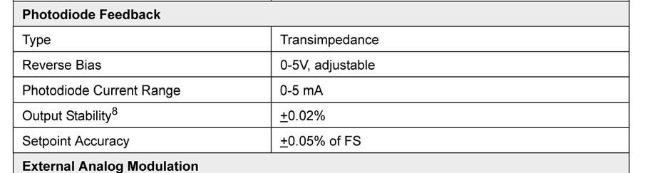
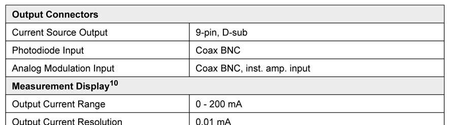
4 2.0 CSM Specifications

5
6 3.0 Installation This section describes the procedures for installing and removing a CSM module from the LDC NOTE - The LDC-3900 will power-up in a default state upon detecting any change in the LDC-3900 system configuration (such as installing a new module). All parameters and SAVE/RECALL settings will be set to default values, based on the new configuration. Calibration data is stored in the CSM module itself, and is never lost due to reconfiguration of the LDC To install the CSM module into the LDC-3900, follow these steps: 1. Turn the LDC-3900 power off. 2. Place the CSM module into an open bay on the back of the LDC-3900 and slide the module into place. There are tracks at the top and bottom of the bay which guide the module into place. Push the module into place until the board edge clicks into place with an audible "pop." This indicates that the module is "locked" into place. Screw the Module Locking Screws into the back panel to secure the module. It is then ready to be used in the LDC Power-up the LDC After the LDC-3900 has completed its power-up sequence, the (ADJUST) LAS indicator which corresponds to the newly installed CSM module should be lit in green, indicating that the module has been recognized as a LASER current source in its respective bay. To remove the CSM module from the LDC-3900, follow these steps: 1. Turn the LDC-3900 power off. 2. Unscrew the Module Locking Screws which secure the module to the LDC-3900 back panel. 3. Grasp the CSM module by handle which extends from the bottom of the back panel. Gently, but firmly, pull the module out of the LDC If the CSM module is replaced in the LDC-3900 before the LDC-3900 is powered up again, the LDC-3900 will retain its memory of all parameter settings and SAVE/RECALL values. However, if the LDC-3900 is powered up and detects a change in its system configuration, all parameters and SAVE/RECALL information will be lost. Calibration data is stored in the CSM module itself, and is never lost due to reconfiguration of the LDC
7 4.0 Operation This section describes the procedures for connecting and running a laser diode with the CSM module. Refer to Chapter 2 of the LDC-3900 Instruction Manual for front panel description and operation. Refer to Figure 4.1 for the following discussion of connections to the CSM ma Module Locking Screw CURRENT SOURCE MODULATION Modulation Connector Monitor Photodiode Bias Adjust 20mA/V PD BIAS ADJUST PHOTODIODE Auxiliary Monitor Photodiode Feedback Connector 1,2 INTLK 3 CHAS GND 4,5 LSR CATH 6 PD CATH + 7 PD ANOD - 8,9 LSR ANOD Laser Diode Connector Module Locking Screw Figure 4.1 CSM Back Panel
8 4.1 The LASER Connector On the back panel of the CSM you will find a 9-pin D-connector for the LD connections. The pinout diagram for this connector is shown in Figure , 2 Interlock 3 Chassis Ground 4, 5 Laser Cathode 6 PD Cathode (+) 7 PD Anode (-) 8, 9 Laser Anode Figure 4.2 Back Panel LD Connector 4.2 Connecting to Your Laser When connecting laser diodes and other sensitive devices to the CSM-39020, we recommend that the LDC-3900 be powered up and the LASER output be off (LASER MODE ON LED unlit). In this condition, a low impedance shunt is active across the output terminals. When disconnecting devices, it is only necessary to turn the LASER Output off. 4.3 Laser Diode Connections and Shielding IMPORTANT Before connecting the laser diode to the LDC-3900 Modular Laser Diode Controller, be sure that the front panel (LASER MODE) ON switch is in the OFF position (ON LED unlit). Before turning on the LASER output, be sure that the current limit has been correctly set. Figures 4.3 A - D show the possible configurations of connecting laser diodes and photodiodes with the LDC-3900 Modular Laser Diode Controller
9 OUTPUT 3900 Modular Laser Diode Controller 7 6 8, 9 Bias , 5 P. D. L. D. 3 Earth Ground Figure 4.3A Common Laser Cathode - Photodiode Cathode OUTPUT 3900 Modular Laser Diode Controller 7 6 8, 9 Bias , 5 P. D. L. D. 3 Earth Ground Figure 4.3B Common Laser Cathode - Photodiode Anode
10 OUTPUT 3900 Modular Laser Diode Controller 7 6 8, 9 Bias , 5 P. D. L. D. 3 Earth Ground Figure 4.3C Common Laser Anode - Photodiode Cathode OUTPUT 3900 Modular Laser Diode Controller 7 6 8, 9 Bias , 5 P. D. L. D. 3 Earth Ground Figure 4.3D Common Laser Anode - Photodiode Anode
11 IMPORTANT The cable connections to the laser must be secure enough that they won't open-circuit, should they be jostled or bumped. Should an open circuit occur during laser operation, the LASER output will be turned off (OUTPUT LED unlit) automatically. Experience indicates that should an open circuit occur during laser operation (while the LASER is ON), the laser may be damaged by a momentary circuit break-and-remake before the final circuit break. Therefore, although the CSM provides a proprietary debounce protection circuit for the LASER output, secure cabling is important. It is recommended that the connections to the CSM output be made using twisted wire pairs with an earthgrounded shield (see Figures 4.3 A - D). The output terminals of the unit are left floating relative to earth ground to suppress AC power-on/power-off transients that may occur through an earth-ground path. If the output circuit is earth-grounded at some point (such as through the laser package and mount), the user must be careful to avoid multiple earth grounds in the circuit. Multiple earth grounds may provide circuit paths that induce spurious currents in the photodiode feedback circuit and output leads. 4.4 Photodiode Feedback Connections The connector on the back panel of the CSM contains the current supply output. The photodiode signal is input at the connector at pins 6 and 7 (see Figure 4.2). The CSM provides an adjustable reverse bias of 0-5 V for the photodiode. To set the photodiode bias to 5 volts reverse bias, turn the back panel PHOTODIODE BIAS ADJUST fully clockwise. To set the photodiode bias to 0 volts reverse bias, turn the back panel PHOTODIODE BIAS ADJUST fully counter-clockwise. The photodiode feedback may also be connected via the PHOTODIODE (BNC) connector, located on the CSM back panel. Many laser diode modules contain an internal photodiode that monitors the back-facet emission of the laser. Usually, this photodiode is internally connected to either the laser anode or cathode. Figures 4.2A - 4.2D show the recommended connections and shielding for the various configurations of laser diode modules and photodiode feedback schemes. The photodiode and laser inputs on the CSM are electrically isolated from ground and each other. So, if a 4-pin connection is made (no common connections) no additional jumpers are required. Figures 4.2A - 4.2D show the recommended connections and shielding for 3-pin lasers (where the common connection is internal to the device). A 4-pin laser should be connected with the same shielding as shown in Figure 4.2, but the common connection (between the photodiode and the laser) is optional. 4.5 Grounding Considerations The LASER outputs of the CSM are isolated from chassis ground allowing either output terminal to be grounded at the user's option. Figure 4.3 shows the proper earth-ground shielding for laser diode/photodiode connections
12 4.6 Modulation Connections The MODULATION connector allows a 20 mv/a modulation signal to be applied to the laser. The modulation port input impedance is 10 k. 5.0 Calibration The CSM should be calibrated every 12 months or whenever performance verification indicates that calibration is necessary. All calibrations can be done with the case closed. The instrument is calibrated by changing the internally stored digital calibration constants. 5.1 Recommended Equipment Recommended test equipment for calibrating the CSM is listed in Table 5.1. Equipment other than that shown in the table may be used if the specifications meet or exceed those listed. If your LDC-3900 is equipped with the model 1231 GPIB/IEEE interface you may refer to sections 5.4.2, and for calibration procedures using the GPIB, if desired. RECOMMENDED TEST EQUIPMENT Description Mfg./Model Specification DMM HP 3457A 0.1 A or 0.1 mv resolution Resistor 49, 5 W, low TCR, for voltage cal. I PD Calibration Resistors Metal Film 49, and 100, 1%, 1/4 W High-power 10, 5 W, low TCR Optical Isolator TIL117 or equivalent, 6-pin Connector D-sub 9-pin male Table 5.1 Recommended Test Equipment 5.2 Environmental Conditions Calibrate this instrument under laboratory conditions. We recommend calibration at 23 C ± 1.0 C. When necessary, however, the CSM may be calibrated at its intended use temperature if this is within the specified operating temperature range of 0 to 50 C. 5.3 Warm-Up The LDC-CSM should be allowed to warm up for at least 1 hour before calibration
13 5.4 LASER Controller Calibration Procedures There are three calibration procedures that need to be made for the CSM They are calibration of the constant current source (for both bandwidths), calibration of the laser voltage measurement, and calibration of the constant light power (I PD ) feedback circuits. The CSM implements a two-point calibration for the Laser current source. Two currents are applied to a load, and the resulting measured currents are fed back (by the user) to the CSM The CSM calibration program uses the two data points to calculate calibration constants that it will thereafter use to set current. If you have the optional Model 1231 IEEE-488.2/GPIB interface you may follow the procedure in sections 5.4.2, 5.4.4, and to calibrate the CSM remotely Local Operation Current Source Calibration The following procedure is for local (front panel) operation. See Section for remote calibration of the current source. a. Select the CSM to be calibrated by pressing the appropriate (ADJUST) switch. Set the LASER current limit (LIM I) to full scale, bandwidth as desired, and current set point to 160 ma (80% of full scale). Connect a calibrated DMM to measure the current across the output (pins 5 and 8). b. Turn the (LASER ENABLE) ON switch and press the appropriate OUTPUT switch to turn the LASER output on. If the LASER output is not on, the LASER I calibration mode cannot be entered. If the LASER output is on, but the LASER channel is not selected (see Step a), calibration will be performed improperly. c. Enter the LASER I calibration mode by pushing the (GPIB) LOCAL and (LASER DISPLAY) I switches at the same time. The LASER display will indicate output current in ma. The LDC-3900 will beep when it is ready to accept a new calibration value. d. Press and hold in the (PARAMETER) SET switch and turn the ADJUST knob until the LASER display indicates the same current as measured via the DMM. e. Release the (PARAMETER) SET switch to accept the first calibration value. After the (LASER DISPLAY) SET switch is released, the LDC-3900 will beep. It will then apply the second calibration current, approximately one-fourth of the original current. f. The LDC-3900 will beep when it is ready to accept the second calibration value. When it does, press and hold in the (PARAMETER) SET switch and turn the ADJUST knob until the LASER display indicates the same current as measured via the DMM. g. Release the (PARAMETER) SET switch to accept the second calibration value. After the (PARAMETER) SET switch is released, the LDC-3900 will calculate the calibration constants, store them to nonvolatile memory on the CSM-39020, beep, and return to its former (before calibration) state. h. Repeat this procedure with the other bandwidth, if desired
14 5.4.2 Remote Operation Current Source Calibration The following procedure is for remote (GPIB) operation. See Section for local calibration of the current source. a. Select the CSM to be calibrated by sending the "LAS:CHAN x" command, where x is the channel of the CSM Set the LASER limit to full scale via the "LAS:LIM:I 200" command, output bandwidth as desired via the "LAS:MODE" command, and current set point to 80% of full scale via the "LAS:LDI 160" command. Connect a calibrated DMM to measure the current across the laser output (pins 5 and 8). b. Turn the (LASER ENABLE) ON switch. Enter the "LAS:OUT ON" command to turn the LASER output on. If the LASER output is not on, the LASER I calibration mode cannot be entered. c. Enter the LASER I calibration mode by issuing the "LAS:CAL:LDI" command. The LDC-3900 will beep when it is ready to accept the first calibration point. d. Input the first actual (measured) LASER output current (as an <nrf value>) via the "LAS:LDI <nrf value>" command. If this value is to be measured and entered remotely via a GPIB controlled DMM, for example, the measured value of the current should not be entered until the LDC-3900 is ready to receive it. The LDC-3900 will be ready to receive the current value when, after a "LAS:CAL:LDI?" query is sent, the response from the LDC-3900 is "1". e. Once the actual I value is entered via the "LAS:LDI" command, the LDC-3900 will beep and will apply a new current equal to approximately one-fourth (1/4) the previous set current. The LDC-3900 will be ready to receive the second current value when, after a "LAS:CAL:LDI?" query is sent, the response from the LDC-3900 is "1". f. Input the second actual (measured) LASER output current (as an <nrf value>) as in Step d. g. Once the second actual I value is entered via the "LAS:LDI" command, the LDC-3900 will beep and the new calibration constants will be calculated and stored into non-volatile memory on the CSM The "OPC?" query may be used (after the "LAS:LDI" value is sent) to determine when the calibration is completed. The operation complete flag (bit 0 of the Standard Event Status Register) may be used to trigger a service request. This type of interrupt is enabled by setting bit 0 of the Service Request Enable register (via the *ESE command) and bit 5 of the Service Request Enable register (via the *SRE command). Service request (SRQ) handling depends on your GPIB hardware. Refer to your GPIB user's manual for details. h. Repeat this procedure with the other range, if desired
15 5.4.3 Local Operation I PD Current Calibration The following procedure is for calibrating the LASER I PD constant current source. This procedure calibrates the feedback circuits for constant I PD and constant P PD modes. When these values are reached and are stable, the user enters the actual value of the current, as measured by an external DMM. The CSM then automatically calibrates the LASER feedback circuits. This procedure is for local (front panel) operation. See Section for remote calibration of the I PD current. a. Select the CSM to be calibrated by pressing the appropriate (ADJUST) switch. With the LASER output off, connect a calibrated ammeter to the PD Anode output of the CSM-39020, and connect the circuit of Figure 5.1 to the LASER and PD outputs. If a calibrated ammeter (with 0.1 A resolution) is not available, place a calibrated DMM (with 0.1 mv resolution) to measure the voltage across the resistor, R1, as shown in Figure 6.1. Calculate the current in the following steps by using Ohm's Law: I = E / R -where E is the accurately measured voltage across the resistor, and R is the accurately measured load resistance. (A 4-point probe resistance measurement is recommended.) Interlock - (1) Interlock - (2) LD Cathode (5) LD Anode (9) PD Cathode + (6) PD Anode - (7) R4 1 M 9-Pin D-Sub Ammeter 9 V Batt A V Voltmeter Ipd Current R U1 TIL R2 100 R3 CALIBRATION CIRCUIT Figure 5.1 I PD Calibration Circuit b. Set the LASER current limit (LIM I) to 200 ma. Set the I PD set point to 4000 A, and set the CAL PD parameter to zero. This puts the CSM into a constant I PD mode. c. Turn the (LASER ENABLE) ON switch and press the appropriate OUTPUT switch to turn the LASER output on. If the LASER output is not on, the LASER I PD calibration mode cannot be entered. d. Press the (GPIB) LOCAL and (LASER DISPLAY) I PD /P PD switches at the same time to place the CSM in its LASER I PD Calibration mode. After a few seconds the LDC-3900 will beep and the LASER display will show the I PD set point value. e. After the value on the LASER display is stable (has not changed by more than one digit for several seconds) the CSM is ready for the actual I PD value to be entered
16 Press and hold in the (PARAMETER) SET switch and turn the ADJUST knob until the LASER display shows the correct value, as shown on the calibrated ammeter (or the calculated I PD value from Step a). f. Release the (PARAMETER) SET switch to store the first calibration value into non-volatile memory. It will then expect the second calibration current current, approximately one-fourth of the original current. g. The LDC-3900 will beep when it is ready to accept the second calibration value. When it does, press and hold in the (PARAMETER) SET switch and turn the ADJUST knob until the LASER display indicates the same current (as measured directly, or as calculated in Step a, from the measured voltage). h. Release the (PARAMETER) SET switch to accept the second calibration point. After the (PARAMETER) SET switch is released, the LDC-3900 will calculate the calibration constants, store them to nonvolatile memory on the CSM-39020, beep, and return to its former (before calibration) state Remote Operation I PD Current Calibration The following procedure is for calibrating the LASER I PD constant current source over GPIB. This procedure calibrates the feedback circuits for constant I PD and constant P PD modes. When these values are reached and are stable, the user enters the actual value of the current, as measured by an external DMM. The CSM then automatically calibrates the LASER feedback circuits. This procedure is for remote (GPIB) operation. See Section for local calibration of the I PD current. a. With the LASER output off, connect a calibrated ammeter to the PD Anode output of the CSM-39020, and connect the circuit of Figure 5.1 to the LASER and PD outputs. If a calibrated ammeter (with 0.1 A resolution) is not available, place a calibrated DMM (with 0.1 mv resolution) to measure the voltage across the resistor, R1, as shown in Figure 5.1. Calculate the current in the following steps by using Ohm's Law: I = E / R -where E is the accurately measured voltage across the resistor, and R is the accurately measured load resistance. (A 4-point probe resistance measurement is recommended.) b. Select the CSM to be calibrated by sending the "LAS:CHAN x" command, where x is the channel of the CSM Set the LASER current limit via the "LAS:LIM:I 200" command. Set the I PD set point to 4000 A via the "LAS:MDI 4000" command. Set the CAL PD parameter to zero via the "LAS:CALMD 0" command. This puts the CSM into a constant I PD (MDI) mode. c. Turn the (LASER ENABLE) ON switch. Enter the "LAS:OUT ON" command to turn the LASER output on. If the LASER output is not on, the LASER I PD calibration mode cannot be entered. d. Enter the "LAS:CAL:MDI" command to place the CSM in its LASER I PD Calibration mode. e. After a few seconds, the LDC-3900 will be ready for the actual I PD current to be entered via the "LAS:MDI" command. The measured value of the current should not be entered until the LDC-3900 is ready to receive it. The LDC-3900 will beep when it is ready to accept a new calibration value. The LDC-3900 will be ready to receive the I PD value when, after a "LAS:CAL:MDI?" query is sent, the response from the LDC-3900 is "1"
17 f. Once the actual I value is entered via the "LAS:MDI" command, the LDC-3900 will beep and the new calibration value will be stored into non-volatile memory. It will then set the current to approximately onefourth of the original current and expect the second calibration value to be entered. The LDC-3900 will be ready to receive the second I PD value when, after a "LAS:CAL:MDI?" query is sent, the response from the LDC-3900 is "1". g. Input the second actual (measured) I PD current (as an <nrf value>) as in Step e. h. Once the second actual monitor diode current value is entered via the "LAS:MDI" command, the LDC-3900 will beep and the new calibration constants will be calculated and stored into non-volatile memory in the CSM The "OPC?" query may be used (after the "LAS:MDI" value is sent) to determine when the calibration is completed. The operation complete flag (bit 0 of the Standard Event Status Register) may be used to trigger a service request. This type of interrupt is enabled by setting bit 0 of the Service Request Enable register (via the *ESE command) and bit 5 of the Service Request Enable register (via the *SRE command). Service request (SRQ) handling depends on your GPIB hardware. Refer to your GPIB user's manual for details Local Operation Laser Voltage Measurement Calibration The following procedure is for calibrating the LASER voltage measurement via the front panel. See Section for remote (GPIB) calibration of the voltage measurement. a. With the LASER output off, connect a calibrated voltmeter, in parallel with a 49, 5 Watt, low temperature coefficient resistor, to the LASER output of the CSM (pins 5 and 8). b. Select the CSM to be calibrated by pressing the appropriate (ADJUST) switch. Set the LASER current limit (LIM I) to 200 ma. Set the LASER I set point to 120 ma. c. Turn the (LASER ENABLE) ON switch and press the appropriate OUTPUT switch to turn the LASER output on. If the LASER output is not on, the LASER voltage calibration mode cannot be entered. d. Press the (GPIB) LOCAL and (LASER DISPLAY) V switches at the same time to place the CSM in its LASER Voltage Calibration mode. e. After a few seconds, the LDC-3900 will beep when it is ready to accept a new calibration value. Press and hold in the (PARAMETER) SET switch and turn the ADJUST knob to enter the LASER voltage measurement value which appears on the DMM. Release the (PARAMETER) SET switch to enter the value. Once the actual voltage value is entered, the LDC-3900 will beep. It will then set the output to approximately one-fourth of the original voltage, and then it will expect the second calibration voltage point to be entered f. Input the second actual (measured) LASER voltage (as an <nrf value>) as in Step e. g. Once the second actual voltage value is entered, the LDC-3900 will beep and the new calibration constants will be calculated and stored into non-volatile memory on the CSM Remote Operation Laser Voltage Measurement Calibration The following procedure is for calibrating the LASER voltage measurement via GPIB. See Section for local calibration of the voltage measurement
18 a. With the LASER output off, connect a calibrated voltmeter, in parallel with a 49, 5 Watt, low temperature coefficient resistor, to the LASER output of the CSM (pins 5 and 8). b. Select the CSM to be calibrated by sending the appropriate "LAS:CHAN x" command, where x is the channel number of the CSM Set the LASER current limit via the "LAS:LIM:I 200". Set the I set point via the "LAS:LDI 120" command. c. Turn the (LASER ENABLE) ON switch. Enter the "LAS:OUT ON" command to turn the LASER output on. If the LASER output is not on, the LASER voltage calibration mode cannot be entered. d. Enter the "LAS:CAL:LDV" command to place the CSM in its LASER Voltage Calibration mode. e. After a few seconds, the LDC-3900 will be ready for the actual laser voltage to be entered via the "LAS:LDV" command. The measured value of the voltage should not be entered until the LDC-3900 is ready to receive it. The LDC-3900 will be ready to receive the voltage value when, after a "LAS:CAL:LDV?" query is sent, the response from the LDC-3900 is "1". f. Once the actual voltage value is entered via the "LAS:LDV" command, the LDC-3900 will beep. It will then expect the second calibration voltage point, approximately one-fourth of the original voltage. The LDC-3900 will be ready to receive the second voltage value when, after a "LAS:CAL:LDV?" query is sent, the response from the LDC-3900 is "1". g. Input the second actual (measured) LASER voltage (as an <nrf value>) as in Step e. h. Once the second actual voltage value is entered via the "LAS:LDV" command, the LDC-3900 will beep and the new calibration constants will be calculated and stored into non-volatile memory on the CSM The operation complete flag (bit 0 of the Standard Event Status Register) may be used to trigger a service request. This type of interrupt is enabled by setting bit 0 of the Service Request Enable register (via the *ESE command) and bit 5 of the Service Request Enable register (via the *SRE command). Service request (SRQ) handling depends on your GPIB hardware. Refer to your GPIB user's manual for details
Artisan Scientific is You~ Source for: Quality New and Certified-Used/Pre:-awned ECJuiflment
 Looking for more information? Visit us on the web at http://www.artisan-scientific.com for more information: Price Quotations Drivers Technical Specifications. Manuals and Documentation Artisan Scientific
User s Guide Current Source / TE Controller Module LCM-39425
 User s Guide Current Source / TE Controller Module LCM-39425 ILX Lightwave 31950 Frontage Road Bozeman, MT, U.S.A. 59715 U.S. & Canada: 1-800-459-9459 International Inquiries: 406-556-2481 Fax 406-586-9405
User s Guide Current Source / TE Controller Module LCM-39427/437
 User s Guide Current Source / TE Controller Module LCM-39427/437 ILX Lightwave 31950 Frontage Road Bozeman, MT, U.S.A. 59715 U.S. & Canada: 1-800-459-9459 International Inquiries: 406-556-2481 Fax 406-586-9405
Artisan Technology Group is your source for quality new and certified-used/pre-owned equipment
 Artisan Technology Group is your source for quality new and certified-used/pre-owned equipment FAST SHIPPING AND DELIVERY TENS OF THOUSANDS OF IN-STOCK ITEMS EQUIPMENT DEMOS HUNDREDS OF MANUFACTURERS SUPPORTED
User s Guide 32 Watt Temperature Control Module TCM-39034
 User s Guide 32 Watt Temperature Control Module TCM-39034 ILX Lightwave Corporation 31950 Frontage Road Bozeman, MT, U.S.A. 59715 U.S. & Canada: 1-800-459-9459 International Inquiries: 406-556-2481 Fax
User s Guide Laser Diode Current Source Modules LDC Series
 User s Guide Laser Diode Current Source Modules LDC-3916330 Series ILX Lightwave Corporation 31950 Frontage Road Bozeman, MT, U.S.A. 59715 U.S. & Canada: 1-800-459-9459 International Inquiries: 406-556-2481
LDD M SERIES INSTRUCTION MANUAL LDD M SERIES
 TM LDD M SERIES LDD M SERIES INSTRUCTION MANUAL P O Box Bozeman, MT 9 Phone (0) -90 Fax (0) -9 email sales@wavelengthelectronics.com www.wavelengthelectronics.com TABLE OF CONTENTS Features... Customer
User s Guide. Precision Current Source LDX-3200 Series. ilx.custhelp.com
 User s Guide Precision Current Source LDX-3200 Series ILX Lightwave 31950 Frontage Road Bozeman, MT, U.S.A. 59715 U.S. & Canada: 1-800-459-9459 International Inquiries: 406-556-2481 Fax 406-586-9405 ilx.custhelp.com
Model 500 Series Laser Diode Driver User's Manual
 Model 500 Series Laser Diode Driver User's Manual .0 INTRODUCTION The Model 500 Series Laser Diode Drivers are low noise, highly stable current sources for use with laser diodes. Selectable output current
LDC. Flexible, Comprehensive Control of Laser Diodes. Modular Laser Diode Controller. Product Features
 Product Features 4 independent channels with 8 isolated outputs Laser current source modules from 200mA to 8A LD controller modules from 200mA to 2A with integrated 12W TEC 32W TEC only modules with voltage
LDC 3700C Series. The Standard for High Performance Laser Diode Control. Laser Diode Controllers. Product Features
 Product Features Laser diode current source with integrated 32W temperature controller Three models available with up to 4A laser drive current USB remote interface GPIB/IEEE-488 remote interface High
# 6. Choosing the Right Laser Diode Mount for Your Application
 # 6 Choosing the Right Laser Diode Mount for Your Application Introduction The multitude of laser diode packages available today make selecting the correct mount for laboratory, development, or production
PLD Series +5V Laser Diode Drivers
 PLD Series +5V Laser Diode Drivers General Description The PLD series of Laser Diode Drivers combines the high performance you expect from a Wavelength component with two distinct improvements: low voltage
LDC 3700B Series. Preliminary. The Standard for High-Performance Laser Diode Control. Laser Diode Controllers. Product Features
 Product Features Laser diode current source with integrated 32W temperature controller Three models available with up to 4A laser drive current GPIB/IEEE-488 remote interface High stability, low noise
Thorlabs Model LD1100
 Thorlabs Model LD1100 Constant Power Laser Driver THORLABS, Inc. PO Box 366 435 Route 206N Newton, NJ 07860 (973) 579-7227 Phone (973) 383-8406 Fax http://www.thorlabs.com Page 1 of 15 Table of Contents
Butterfly Laser Diode Mount
 LM14S2 Butterfly Laser Diode Mount Operating Manual LM14S2 Laser On TEC Driver LD Driver THORLABS, Inc. Ph: (973) 579-7227 435 Route 206N Fax: (973) 383-8406 Newton, NJ 07860 USA www.thorlabs.com 10614-D02
manufactured by SF8150-ZIF14
 manufactured by manufactured by SF8150- ZIF14 Butterfly packaged laser diode controller Datasheet & Users Manual Before powering on your driver, read this manual thoroughly. If you have any doubt or suggestion,
Model 8016 / 9008 / 9016 Modular Controller. User's Manual
 Model 8016 / 9008 / 9016 Modular Controller User's Manual Newport Corporation, Irvine, California, has been certified compliant with ISO 9002 by the British Standards Institution. Corporate Headquarters
Artisan Technology Group is your source for quality new and certified-used/pre-owned equipment
 Artisan Technology Group is your source for quality new and certified-used/pre-owned equipment FAST SHIPPING AND DELIVERY TENS OF THOUSANDS OF IN-STOCK ITEMS EQUIPMENT DEMOS HUNDREDS OF MANUFACTURERS SUPPORTED
MANUAL FOR THE UNIVERSAL MANUAL CONTROLLER UMC - 31
 MANUAL FOR THE UNIVERSAL MANUAL CONTROLLER UMC - 31 PPS PART NO. 133550 DRAWING NO. 133550-10 THIS MANUAL ASSIGNED TO THE S/N: THE INFORMATION CONTAINED IN THIS MANUAL IS PROPRIETARY TO PACIFIC POWER SOURCE,
Isolated Wideband Voltage Input 3B40 / 3B41 FEATURES APPLICATIONS PRODUCT OVERVIEW FUNCTIONAL BLOCK DIAGRAM
 Isolated Wideband Voltage Input 3B40 / 3B41 FEATURES Interfaces, amplifies, protects& filters wide-bandwidth (h0 khz) single-channel analog voltage inputs. Module provides simultaneous precision voltage
Before powering on your driver, read this manual thoroughly. If you have any doubt or suggestion, please do not hesitate to contact us!
 Laser diode driver Datasheet & UserManual Before powering on your driver, read this manual thoroughly. If you have any doubt or suggestion, please do not hesitate to contact us!, 37 Sedova St, Off 209,
WORLD LEADING PRODUCTS FOR LASER SCIENTISTS AND ENGINEERS
 High Voltage Laser Diode Driver with up to 48 Volts, 15 Amps for Series Connected Devices Up to 48 Volts, 15 Amps (CW) Designed for Multi-Chip and Series Connected Laser Diodes Requiring High Voltage Compact
ADDJOG User Guide 7/30/10. Overview
 ADDJOG User Guide 7/30/10 Overview The ADDJOG is a PLC expansion board used to add digital inputs and outputs to a compatible host PLC. The ADDJOG has 64 open collector outputs and 64 non-isolated inputs.
Isolated Voltage Input 3B30 / 3B31 FEATURES APPLICATIONS PRODUCT OVERVIEW FUNCTIONAL BLOCK DIAGRAM
 Isolated Voltage Input 3B30 / 3B31 FEATURES Interfaces, amplifies, & filtersanalog input voltages. Narrow-bandwidth (3Hz) single-channel single conditioning. Module provides simultaneous precision voltage
Model 8000/8008 Modular Controller User's Manual
 Model 8000/8008 Modular Controller User's Manual Newport Corporation, Irvine, California, has been certified compliant with ISO 9002 by the British Standards Institution. Corporate Headquarters Canada
UNIVERSAL MOTION INTERFACE (UMI) ACCESSORY
 ACCESSORY") USER GUIDE UNIVERSAL MOTION INTERFACE (UMI) ACCESSORY Contents This user guide describes how to use the UMI-77, UMI-A, UMI-Flex, and UMI-Flex accessories. Introduction... What You Need to Get Started...
USER GUIDE UNIVERSAL MOTION INTERFACE (UMI) ACCESSORY Contents This user guide describes how to use the UMI-77, UMI-A, UMI-Flex, and UMI-Flex accessories. Introduction... What You Need to Get Started...
UNIVERSAL MOTION INTERFACE (UMI) ACCESSORY
 ACCESSORY") USER GUIDE UNIVERSAL MOTION INTERFACE (UMI) ACCESSORY Introduction This user guide describes how to use the UMI-A, UMI-Flex, and UMI-Flex accessories. The UMI products are connectivity accessories you
USER GUIDE UNIVERSAL MOTION INTERFACE (UMI) ACCESSORY Introduction This user guide describes how to use the UMI-A, UMI-Flex, and UMI-Flex accessories. The UMI products are connectivity accessories you
9823 Multifunction Calibrator Calibration Adjustment Procedure
 9823 Multifunction Calibrator Calibration Adjustment Procedure Time Electronics Ltd BOTANY INDUSTRIAL ESTATE TONBRIDGE, KENT, TN9 1RH, UK Tel: 01732 355993 Fax: 01732 770312 Email: mail@timeelectronics.co.uk
CS485. User s Manual. Version ZYPEX, Inc.
 CS485 User s Manual Version 2.0 2003 ZYPEX, Inc. Table of Contents Product Description 1 CS485 Configuration & Setup 2 4-wire Operation 2 2-wire Operation 2 Dual Port Operation 2 Carrier Detect 2 Transmitter
OBSOLETE. Isolated, Linearized, Thermocouple Input 3B47 FEATURES APPLICATIONS PRODUCT OVERVIEW FUNCTIONAL BLOCK DIAGRAM
 FEATURES Interfaces, amplifies, filters, isolates, & linearizes analog input voltages from a J, K, T, E, R, S or B-type thermocouple Thermocouple input signal is internally linearized High accuracy internal
Model 3750 Multifunction I/O Card
 Keithley Instruments, Inc. 28775 Aurora Road Cleveland, Ohio 44139 1-888-KEITHLEY www.keithley.com Model 3750 Multifunction I/O Card Connection Instructions and Specifications Introduction This instruction
laser controllers, modular chassis page 1 of 2
 ELECTRONICS 3-364-373.qxd 8/28/03 4:14 PM Page 364 laser controllers, modular chassis page 1 of 2 Introduction - PRO8000 Series The modular design of the PRO8000 series provides a flexible solution to
MDK. Accelnet Module DevKit. Provides Mounting & Connections for Accelnet CANopen Servoamplifiers FEATURES
 Provides Mounting & Connections for Accelnet CANopen Servoamplifiers FEATURES Works with all Accelnet Models Develop & Debug Accelnet projects then transfer design to oem pc board. Dev Kit Model * Vdc
CDN503 HIGH DENSITY I/O ADAPTER USER GUIDE
 CDN503 HIGH DENSITY I/O ADAPTER USER GUIDE 13050301 (c) Copyright DIP Inc., 1996 DIP Inc. P.O. Box 9550 MORENO VALLEY, CA 92303 714-924-1730 CONTENTS DN503 PRODUCT OVERVIEW 1 DN503 INSTALLATION 1 POWER
Compact Laser Diode Driver Version 2.4 cldd User s Guide
 Compact Laser Diode Driver Version 2.4 cldd User s Guide Innolume GmbH Index 1. GENERAL INFORMATION... 3 1.1. SAFETY... 3 1.2. PRODUCT OVERVIEW... 3 2. TECHNICAL DATA... 4 2.1. SPECIFICATIONS... 4 2.2.
User s Guide. RP7000S Series Single-Ended Active Probe. Nov RIGOL Technologies, Inc.
 User s Guide RP7000S Series Single-Ended Active Probe Nov. 2013 RIGOL Technologies, Inc. Guaranty and Declaration Copyright 2013 RIGOL Technologies, Inc. All Rights Reserved. Trademark Information RIGOL
RTD-500 Precision RTD Simulator. Operations Manual.
 RTD-500 Precision RTD Simulator Operations Manual. Page 1 of 16 Table of Content. Table of Content....1 1 Scope...3 2 Package Content....3 3 Technical Data....3 4 Preparation for use....4 4.1 Switching
Page DR Series LaserSource User s Manual. Table of Contents
 Page 2 4200-DR Series LaserSource User s Manual Table of Contents Introduction... 3 Safety Terms and Symbols... 4 Quick Start... 6 Installation... 7 Operation... 9 Settings and Menus... 12 Saving and Restoring
MT400 MOTION CONTROLLER
 MT400 MOTION CONTROLLER INSTALLATION & TECHNICAL MANUAL 5/30/2012 417 Wards Corner Road Loveland, OH 45140 800.659.8250 FAX: 513.398.2536 www.maxitronic.com Table of Contents Page 3: Page 4: Page 5: Page
JR3 EXTERNAL SENSOR ELECTRONICS WITH SERIAL DATA OUTPUT. JR3, Inc. 22 Harter Ave. Woodland, CA 95776
 JR3 EXTERNAL SENSOR ELECTRONICS WITH SERIAL DATA OUTPUT JR3, Inc. 22 Harter Ave. Woodland, CA 95776 5963B 13 October, 2003 TABLE OF CONTENTS CHAPTER 1 OVERVIEW General...1-1 Sensor...1-1 Electronic System...1-1
BC-9000 Field Calibration Procedure CF1_FIELDCAL_BC9000 Revised 03/16/2013
 BC-9000 Field Calibration Procedure CF1_FIELDCAL_BC9000 Revised 03/16/2013 INTRODUCTION: The BC-9000 Battery Charger will recharge12 and 24 volt lead-acid and nickel cadmium batteries. Battery charging
CONNECTING SENSORS TO DATA ACQUISITION SYSTEM ANALOG INPUTS
 CONNECTING SENSORS TO DATA ACQUISITION SYSTEM ANALOG INPUTS Properly connecting sensors to a data acquisition system is as crucial as selecting the proper sensor for the application, and there are multiple
Agilent E3632A DC Power Supply
 Service Guide Part Number: E3632-90010 October 2007. For Warranty information, refer to the back of the manual. Copyright Agilent Technologies, Inc. 2000-2007 All Rights Reserved. Agilent E3632A DC Power
BRC SERIES 20kW High Voltage Power Supply
 BRC SERIES 20kW High Voltage Power Supply Description UNIPOWER s line of BRC switching power supplies are notable for low ripple, fast transient response, endurance to repetitive arcing and stable output
User s Guide Dual Temperature TEC Control Module LDC
 User s Guide Dual Temperature TEC Control Module LDC-3916550 ILX Lightwave Corporation 31950 Frontage Road Bozeman, MT, U.S.A. 59715 U.S. & Canada: 1-800-459-9459 International Inquiries: 406-556-2481
Series 3700 Screw Terminal Assemblies Installation Instructions
 Keithley Instruments, Inc. 28775 Aurora Road Cleveland, Ohio 44139 1-888-KEITHLEY www.keithley.com Series 3700 Screw Terminal Assemblies Installation Instructions Introduction This document contains handling
Laser Diode Controller Instruction Manual
 Russia, Moscow Tel. \ fax: (495) 333-93-01 www.nolatech.ru nolatech@mail.ru DLC-200 LD&TEC CONTROLLER Laser Diode Controller Instruction Manual Please read this Instruction Manual before using the unit.
Laser Diode Controller. LDC2xx Series Operation Manual
 Laser Diode Controller LDC2xx Series Operation Manual 2011 2 LDC2xxC Version: 5.1 Date: 18. Mar. 2011 General Information 3 Table of Contents 1 General Information...6 1.1 At a Glance...6 1.1.1 General
Allen-Bradley Drives
 Installation Data This document provides information on: important pre installation considerations power supply requirements installing the module installing and connecting the wiring using the module
Ignitron Driver Manual (N = cable length in meters -example IG5F2-10 = unit with a 10 meter cable length)
") North Star High Voltage 12604 N New Reflection Dr, Marana, AZ 85653 520 780 9030; (206)219-4205 FAX www.highvoltageprobes.com DANGER - Voltages of up to 2.5 kv are generated by this unit Ignitron circuits
North Star High Voltage 12604 N New Reflection Dr, Marana, AZ 85653 520 780 9030; (206)219-4205 FAX www.highvoltageprobes.com DANGER - Voltages of up to 2.5 kv are generated by this unit Ignitron circuits
IST ULTRASTAB Power Supply for high precision transducers
 IST ULTRASTAB Power Supply for high precision transducers High performance 6-channel power supply for multi-channel laboratory measurement applications. Features Current output or ±0 V voltage output (see
OPERATING INSTRUCTIONS AND SYSTEM DESCRIPTION FOR THE HVA-100 HIGH VOLTAGE AMPLIFIER MODULE FOR EPMS SYSTEMS
 OPERATING INSTRUCTIONS AND SYSTEM DESCRIPTION FOR THE HVA-100 HIGH VOLTAGE AMPLIFIER MODULE FOR EPMS SYSTEMS VERSION 1.7 npi 2015 npi electronic GmbH, Bauhofring 16, D-71732 Tamm, Germany Phone +49 (0)7141-9730230;
Operation Manual. Thorlabs Blueline Series. Laser Diode Controller. LDC2xx
 Operation Manual Thorlabs Blueline Series Laser Diode Controller LDC2xx 2004 Version: 2.12 Date: 22.01.2004 Copyright 2004, Thorlabs GmbH, Germany Contents page 1 General description of the laser diode
BIPOLAR OPERATIONAL POWER SUPPLY
 QUICK START GUIDE I INTRODUCTION KEPCO An ISO 9001 Company. BIPOLAR OPERATIONAL POWER SUPPLY 1.1. SCOPE OF MANUAL. This Quick Start Guide covers simple installation and local operation of the Kepco 100W,
DATASHEET AND OPERATING GUIDE LDMOUNT-5A
 DATASHEET AND OPERATING GUIDE LDMOUNT-A A Butterfly 4-Pin Laser Diode Mount FEATURES AND BENEFITS Capable of driving lasers up to A Capable of controlling thermoelectrics up to A Compatible with 4-pin
D115 The Fast Optimal Servo Amplifier For Brush, Brushless, Voice Coil Servo Motors
 D115 The Fast Optimal Servo Amplifier For Brush, Brushless, Voice Coil Servo Motors Ron Boe 5/15/2014 This user guide details the servo drives capabilities and physical interfaces. Users will be able to
PCI-FPGA-1B User Guide
 PCI-FPGA-1B User Guide Rev 1.0 (Nov. 2012) Port City Instruments, LLC 8209 Market Street, Suite A271 Wilmington, NC 28411 (Tel) 866-456-2488 (Web) www.portcityinstruments.com Copyright 2012 Port City Instruments,
MODEL SW6000 & SM6100 CENELEC INSTRUCTIONS
 MODEL SW6000 & SM6100 CENELEC INSTRUCTIONS Installation Manual 1180 METRIX Experience Value 8824 Fallbrook Dr. Houston, TX 77064, USA Tel: 1-281-940-1802 After Hours Technical Assistance: 1-713-702-8805
Wide Bandwidth Strain Gage Input 3B18 FEATURES APPLICATIONS PRODUCT OVERVIEW FUNCTIONAL BLOCK DIAGRAM
 Wide Bandwidth Strain Gage Input 3B18 FEATURES Wideband (20 khz) single-channel signal conditioning module. Module Bandwidth is user-selectable between 20 khz and 100Hz, with user-supplied filter caps
205 CPU NETWORK ADAPTER F2-UNICON
 205 CPU NEWORK ADAPER F2-UNICON Network Adapter he F2-UNICON Network Adapter is used to place Automationdirect.com DL205 CPUs (except D2-230 and D2-250) on a RS-422 or RS-485 multi-drop network. he Network
JR3 EXTERNAL SENSOR ELECTRONICS WITH ANALOG OUTPUT. JR3, Inc. 22 Harter Ave. Woodland, CA 95776
 JR3 EXTERNAL SENSOR ELECTRONICS WITH ANALOG OUTPUT JR3, Inc. 22 Harter Ave. Woodland, CA 95776 5962C 15 December, 2003 TABLE OF CONTENTS CHAPTER 1 OVERVIEW General...1-1 Sensor...1-1 Electronic System...1-1
Page 2 LaserPak User s Manual. Table of Contents
 Page 2 LaserPak User s Manual Table of Contents Introduction... 3 Safety Terms and Symbols... 5 Quick Start... 7 Installation... 8 Control Modes... 10 Settings... 12 Cable Wiring for Modulation... 14 Using
BOP QUICK START GUIDE 100W, 200W, 400W. KEPCO An ISO 9001 Company. BIPOLAR OPERATIONAL POWER SUPPLY I INTRODUCTION
 QUICK START GUIDE I INTRODUCTION KEPCO An ISO 9001 Company. BIPOLAR OPERATIONAL POWER SUPPLY 1.1. SCOPE OF MANUAL. This Quick Start Guide covers simple installation and local operation of the Kepco 100W,
Isolated, Voltage or Current Input 7B30 FEATURES APPLICATIONS PRODUCT OVERVIEW FUNCTIONAL BLOCK DIAGRAM
 Isolated, Voltage or Current Input 7B30 FEATURES Interfaces, amplifies and filters unipolar and bipolar millivolt and voltage inputs. Provides a protected precision output of either +1 V to +5 V or 0 V
IST ULTRASTAB Power Supply for IT/ITN ULTRASTAB transducers
 Power Supply for IT/ITN ULTRASTAB transducers High performance 6-channel power supply for multi-channel laboratory measurement applications. Features Current output or ±10 V voltage output Six individual
MODEL DRIVER Ic Ip VDC
 Provides Mounting & Connections for Stepnet Module CANopen Stepping Driver FEATURES Develop & Debug Stepnet projects then transfer design to OEM pc board. MODEL DRIVER Ic Ip VDC -075-01 STM-075-07 5 7
Series Watt DC Power Supplies
 Keithley Instruments 28775 Aurora Road Cleveland, Ohio 44139 1-800-935-5595 http://www.keithley.com Series 2268 850-Watt DC Power Supplies Specifications SPECIFICATION CONDITIONS This document contains
High Voltage Power Supplies
 Source voltages up to 5kV and 10kV 1µA current measurement resolution Multi-channel programmable DC power supplies Low noise for precision sourcing and sensitive measurements; selectable filters reduce
DATASHEET AND OPERATING GUIDE LDTC0520/LDTC1020
 DATASHEET AND OPERATING GUIDE LDTC0520/LDTC020 Laser Diode & Temperature Controllers FEATURES AND BENEFITS Small package size Single supply operation possible LD current range 500 ma or A Compatible with
OPERATING INSTRUCTION MANUAL FOR THE MODEL GM-700 HALL EFFECT GAUSSMETER
 OPERATING INSTRUCTION MANUAL FOR THE MODEL GM-700 HALL EFFECT GAUSSMETER WARNING! DO NOT ATTEMPT TO OPERATE THIS EQUIPMENT BEFORE YOU HAVE THOROUGHLY READ THIS INSTRUCTION MANUAL. TABLE OF CONTENTS 1.0
HERCULES-5000 INSTRUCTION MANUAL
 IndustrieAlpine Allee 1 D - 94513 Schönberg Tel.:+49 (0) 85 54/9609-0 Fax:+49 (0) 85 54/96 09 20 Mail: sales@tetelectronics.de INSTRUCTION MANUAL HERCULES-5000 High-performance power supplies Page 1 von
SLD-CS-series Compact High Power Broadband Light Source Modules.
 Superlum Broadband Light Sources SLD-CS-series Compact High Power Broadband Light Source Modules. Technical Product Specification Document ID: SL.RD.04.002.150508 December 2015 Revision: 002 ATTENTION
Chapter 1 Introducing the OM-USB Functional block diagram... 5
 Table of Contents Preface About this User's Guide... 4 What you will learn from this user's guide... 4 Conventions in this user's guide... 4 Where to find more information... 4 Chapter 1 Introducing the
Sorensen DLM 600 Series W V 2 75 A. Half Rack Programmable DC Power Supply
 Sorensen DLM 600 Series Half Rack Programmable DC Power Supply high, half rack (8.5 inches) wide; no top or bottom clearance spacing required. rms, noise as low as 15mV p-p. 0-5kΩ. 375 600 W 5 300 V 2
Energy Management System. Operation and Installation Manual
 Energy Management System Operation and Installation Manual AA Portable Power Corp 825 S 19 TH Street, Richmond, CA 94804 www.batteryspace.com Table of Contents 1 Introduction 3 2. Packing List 5 3. Specifications
Installation Instructions
 Installation Instructions This document provides information on: important pre-installation considerations power supply requirements installing the module connecting the wiring using the indicators for
Artisan Technology Group is your source for quality new and certified-used/pre-owned equipment
 Artisan Technology Group is your source for quality new and certified-used/pre-owned equipment FAST SHIPPING AND DELIVERY TENS OF THOUSANDS OF IN-STOCK ITEMS EQUIPMENT DEMOS HUNDREDS OF MANUFACTURERS SUPPORTED
FIRST, A WORD ON SAFETY
 SETUP CONSIDERATIONS FOR YOUR LASER SYSTEM AND WORKSTATION TABLE OF CONTENTS First, a word on safety Protecting your laser from electrostatic discharge Setting up an ESD safe workspace Considerations for
INDEPENDENT ISOLATION FOR CRITICAL COMPONENTS
 ABLE OF CONENS ndependent isolation for critical components Anode and cathode are not connected to ground Slow power-on Accurate current control ntermittent contact safe guard & rate of change detection
DP-PS Laboratory Diode Driver (For use with MK-11, 81, 82, 85, & 88 lasers)
") DP-PS Laboratory Diode Driver (For use with MK-11, 81, 82, 85, & 88 lasers) Kigre manufactures a laboratory laser diode driver for use with the MK-88, 85, 82, 81 and MK-11 laser heads. The driver features
DP-PS Laboratory Diode Driver (For use with MK-11, 81, 82, 85, & 88 lasers) Kigre manufactures a laboratory laser diode driver for use with the MK-88, 85, 82, 81 and MK-11 laser heads. The driver features
Modular Power System 1200 W per mainframe GPIB
 View at www.testequipmentdepot.com High Performance DC Power Supplies 1200 W per mainframe GPIB Modular system permits up to 8 outputs of 150 W per output in 4 U of rack space Reconfigure fast with easily
TOXALERT MODEL AIR 2000
 TOXALERT MODEL AIR 2000 NOTE: Toxalert s Model GVU-CO 2 Sensor is the same as the Air2000R. Microprocessor-based, Infrared Environmental CO 2 Sensor OPERATOR S MANUAL TOXALERT TM INTERNATIONAL INC. P.O.
Mini Digital Multimeter
 User's Guide Mini Digital Multimeter Model MN15 99 Washington Street Melrose, MA 02176 Phone 781-665-1400 Toll Free 1-800-517-8431 Visit us at www.testequipmentdepot.com Back to the Extech MN15/MN16 Series
Table of Contents. Introduction... 2 Description...2 Specifications...3 Installation.. 5 Calibration.. 6 General Maintenance...7
 User's Manual: Series 330I Model 330I DC-Powered Three-Way Isolator Table of Contents Page Introduction... 2 Description....2 Specifications....3 Installation.. 5 Calibration.. 6 General Maintenance...7
GSV-1A4 M12/2 M12/2. Highlights
 GSV-1A4 M12/2 M12/2 Highlights Input sensitivity: 2mV/V; 4mV/V, 2 mv/v, 1mV/V, 0.5mV/V configurable via jumpers Output signals ±10V AND 12mA+-8mA on 15 pin Sub-D Integrated half and quarter bridge completion
Page Series ComboSource User s Manual. Table of Contents
 Page 2 6300 Series ComboSource User s Manual Table of Contents Introduction... 3 Safety Terms and Symbols... 5 Quick Start... 7 Installation... 8 Operation... 11 Settings and Menus... 15 Saving and Restoring
Model INSTRUCTION MANUAL DIGITAL MULTIMETER
 Model 57040 INSTRUCTION MANUAL DIGITAL MULTIMETER SAFETY INFORMATION This multimeter has been designed according to IEC 1010 concerning electronic measuring instruments with an overvoltage category (CAT
Contents. 1.1 Introduction Status-Indicators Connections 5
 Contents. Introduction 3.2 Status-Indicators 4.3 Connections 5 Hardware 2. Power Supply 6 2.2 Module Interface 7 2.3 Input Circuit 9 2.4 Output Circuit 2.5 Error Output 2.6 Analogue Output (IOMA) 2 Software
ABB Drives. User s Manual Pulse Encoder Interface Module MTAC-01
 ABB Drives User s Manual Pulse Encoder Interface Module MTAC-01 Pulse Encoder Interface Module MTAC-01 User s Manual 3AFE68591091 REV B EN EFFECTIVE: 04.04.2006 2006 ABB Oy. All Rights Reserved. 5 Safety
Sorensen DLM 600 Series W V 2 75 A. Half Rack Programmable DC Power Supply
 Sorensen DLM 600 Series Half Rack Programmable DC Power Supply High Power Density: 600 watts in 1U (1.75 inches) high, half rack (8.5 inches) wide; no top or bottom clearance spacing required. Near Linear
Sorensen SG Series - Water Cooled kw V A. Programmable Precision High Power DC Power Supply
 Sorensen SG Series - Water Cooled Programmable Precision High Power DC Power Supply High Power Density: up to 15 kw in 3U Wide Voltage Range: 0-40 V and 0-60 V, in increments of 5 kw from 5 to 15 kw Fast
output devices. connected to the controller. data communications link. relay systems. user program. MECH1500Quiz1ReviewVersion2 Name: Class: Date:
 Class: Date: MECH1500Quiz1ReviewVersion2 True/False Indicate whether the statement is true or false. 1. The number and type of I/Os cannot be changed in a fixed PLC. 2. In a PLC system, there is a physical
SCC-AO10 Isolated Analog Output Module
 USER GUIDE SCC-AO10 Isolated Analog Output Module Conventions The SCC-AO10 is an isolated voltage output module with an output range of ±10 V. The output voltage level is controlled by the DAC output of
Keysight U8030 Series Triple-Output DC Power Supplies
 Keysight U8030 Series Triple-Output DC Power Supplies Data Sheet Introduction Higher Power. Better Reliability. Unrivalled Performance. Keysight Technologies, Inc. extends its family of basic DC power
SLD-mCS/sCS-series Miniature High Power Broadband Light Source Modules
 SLD-mCS/sCS-series Miniature High Power Broadband Light Source Modules Technical Product Specification Document ID: SL.RD.01.001.170215 March 2017 Revision: 002 ATTENTION ELECTROSTATIC SENSITIVE DEVICES
3710 ACM 3750 PDC 3800 RTU. ISOCOM Communications Card Retrofit Instructions
 3710 ACM 3750 PDC 3800 RTU ISOCOM Communications Card Retrofit Instructions Danger During normal operation of this device, hazardous voltages are present which can cause severe injury or death. These
Mini Digital Multimeter
 User Manual Mini Digital Multimeter Model MN15A Additional User Manual Translations available at www.extech.com Introduction Congratulations on your purchase of the Extech MN15A MultiMeter. The MN15A offers
AC/DC Current Probe Model SL201
 AC/DC Current Probe Model SL201 USER MANUAL I ZERO 1 V/A 1 mv/a OFF Limited Warranty The AC/DC Current Probe Model SL201 is warranted to the owner for a period of two years from the date of original purchase
The SilverNugget is a servo controller/driver for NEMA 17 & 23 frame microstep motors.
 Date: 5 November 2008 www.quicksilvercontrols.com SilverNugget N2 M-Grade The SilverNugget is a servo controller/driver for NEMA 17 & 23 frame microstep motors. Property of Page 1 of 13 This document is