SIMATIC. S7-1500/ET 200MP Technology module TM Count 2x24V (6ES7550-1AA00-0AB0) Preface. Documentation guide. Product overview.
|
|
|
- Wilfrid Douglas
- 5 years ago
- Views:
Transcription
1
2 Preface Documentation guide 1 SIMATIC S7-1500/ET 200MP Technology module TM Count 2x24V (6ES7550-1AA00-0AB0) Manual Product overview 2 Wiring 3 Configuring/address space 4 Interrupts/diagnostic messages 5 Technical specifications 6 A Dimensional drawing B Parameter data record 06/2018 A5E AB
3 Legal information Warning notice system This manual contains notices you have to observe in order to ensure your personal safety, as well as to prevent damage to property. The notices referring to your personal safety are highlighted in the manual by a safety alert symbol, notices referring only to property damage have no safety alert symbol. These notices shown below are graded according to the degree of danger. DANGER indicates that death or severe personal injury will result if proper precautions are not taken. WARNING indicates that death or severe personal injury may result if proper precautions are not taken. CAUTION indicates that minor personal injury can result if proper precautions are not taken. NOTICE indicates that property damage can result if proper precautions are not taken. If more than one degree of danger is present, the warning notice representing the highest degree of danger will be used. A notice warning of injury to persons with a safety alert symbol may also include a warning relating to property damage. Qualified Personnel The product/system described in this documentation may be operated only by personnel qualified for the specific task in accordance with the relevant documentation, in particular its warning notices and safety instructions. Qualified personnel are those who, based on their training and experience, are capable of identifying risks and avoiding potential hazards when working with these products/systems. Proper use of Siemens products Note the following: Trademarks WARNING Siemens products may only be used for the applications described in the catalog and in the relevant technical documentation. If products and components from other manufacturers are used, these must be recommended or approved by Siemens. Proper transport, storage, installation, assembly, commissioning, operation and maintenance are required to ensure that the products operate safely and without any problems. The permissible ambient conditions must be complied with. The information in the relevant documentation must be observed. All names identified by are registered trademarks of Siemens AG. The remaining trademarks in this publication may be trademarks whose use by third parties for their own purposes could violate the rights of the owner. Disclaimer of Liability We have reviewed the contents of this publication to ensure consistency with the hardware and software described. Since variance cannot be precluded entirely, we cannot guarantee full consistency. However, the information in this publication is reviewed regularly and any necessary corrections are included in subsequent editions. Siemens AG Division Digital Factory Postfach NÜRNBERG GERMANY A5E AB P 05/2018 Subject to change Copyright Siemens AG All rights reserved
4 Preface Purpose of the documentation This manual includes module-specific information on wiring, diagnostics and the technical specifications of the technology module. General information regarding design and commissioning of the S or ET 200MP is available in the S or ET 200MP system manuals. The counting and measuring functions of the TM Count 2x24V technology module are described in more detail in the Counting, Measurement and Position Detection ( Function Manual. Conventions Please observe notes marked as follows: Note A note contains important information on the product described in the documentation, on the handling of the product and on the section of the documentation to which particular attention should be paid. Security information Siemens provides products and solutions with industrial security functions that support the secure operation of plants, systems, machines and networks. In order to protect plants, systems, machines and networks against cyber threats, it is necessary to implement and continuously maintain a holistic, state-of-the-art industrial security concept. Siemens products and solutions only form one element of such a concept. Customer is responsible to prevent unauthorized access to its plants, systems, machines and networks. Systems, machines and components should only be connected to the enterprise network or the internet if and to the extent necessary and with appropriate security measures (e.g. use of firewalls and network segmentation) in place. Additionally, Siemens guidance on appropriate security measures should be taken into account. For more information about industrial security, please visit ( Siemens products and solutions undergo continuous development to make them more secure. Siemens strongly recommends to apply product updates as soon as available and to always use the latest product versions. Use of product versions that are no longer supported, and failure to apply latest updates may increase customer s exposure to cyber threats. To stay informed about product updates, subscribe to the Siemens Industrial Security RSS Feed under ( Manual, 06/2018, A5E AB 3
5 Preface Open Source Software Open-source software is used in the firmware of the product described. Open Source Software is provided free of charge. We are liable for the product described, including the open-source software contained in it, pursuant to the conditions applicable to the product. Siemens accepts no liability for the use of the open source software over and above the intended program sequence, or for any faults caused by modifications to the software. For legal reasons, we are obliged to publish the original text of the license conditions and copyright notices. Please read the information on this on the Internet ( 4 Manual, 06/2018, A5E AB
6 Table of contents Preface Documentation guide Product overview Properties Functions Detection of counting signals Measured value determination Switching the outputs at comparison values Position input for Motion Control Additional functions Wiring Pin assignment and block diagram Configuring/address space Operating with "Counting and measurement" technology object Configuring Reaction to CPU STOP Parameter setting Address space Isochronous mode Position input for "Motion Control" technology object Configuring Parameter setting Address space Isochronous mode Manual operation (without technology object) Configuring Reaction to CPU STOP Parameter setting Address space Control and feedback interface Assignment of the control interface Assignment of the feedback interface Isochronous mode Interrupts/diagnostic messages Status and error display Diagnostic alarms Hardware interrupts Technical specifications Manual, 06/2018, A5E AB 5
7 Table of contents A Dimensional drawing B Parameter data record B.1 Parameter assignment and structure of parameter data record B.2 Parameter validation error Manual, 06/2018, A5E AB

8 Documentation guide 1 The documentation for the SIMATIC S automation system and the SIMATIC ET 200MP distributed I/O system is arranged into three areas. This arrangement enables you to access the specific content you require. Basic information The System Manual and Getting Started describe in detail the configuration, installation, wiring and commissioning of the SIMATIC S and ET 200MP systems. The STEP 7 online help supports you in the configuration and programming. Device information Product manuals contain a compact description of the module-specific information, such as properties, wiring diagrams, characteristics and technical specifications. General information The function manuals contain detailed descriptions on general topics regarding the SIMATIC S and ET 200MP systems, e.g. diagnostics, communication, motion control, Web server, OPC UA. You can download the documentation free of charge from the Internet ( Changes and supplements to the manuals are documented in a Product Information. You can download the product information free of charge from the Internet ( Manual, 06/2018, A5E AB 7
9 Documentation guide Manual Collection S7-1500/ET 200MP The Manual Collection contains the complete documentation on the SIMATIC S automation system and the ET 200MP distributed I/O system gathered together in one file. You can find the Manual Collection on the Internet ( SIMATIC S comparison list for programming languages The comparison list contains an overview of which instructions and functions you can use for which controller families. You can find the comparison list on the Internet ( "mysupport" With "mysupport", your personal workspace, you make the best out of your Industry Online Support. In "mysupport", you can save filters, favorites and tags, request CAx data and compile your personal library in the Documentation area. In addition, your data is already filled out in support requests and you can get an overview of your current requests at any time. You must register once to use the full functionality of "mysupport". You can find "mysupport" on the Internet ( "mysupport" - Documentation In the Documentation area in "mysupport" you can combine entire manuals or only parts of these to your own manual. You can export the manual as PDF file or in a format that can be edited later. You can find "mysupport" - Documentation on the Internet ( "mysupport" - CAx data In the CAx data area in "mysupport", you can access the current product data for your CAx or CAe system. You configure your own download package with a few clicks. In doing so you can select: Product images, 2D dimension drawings, 3D models, internal circuit diagrams, EPLAN macro files Manuals, characteristics, operating manuals, certificates Product master data You can find "mysupport" - CAx data on the Internet ( 8 Manual, 06/2018, A5E AB
10 Documentation guide Application examples The application examples support you with various tools and examples for solving your automation tasks. Solutions are shown in interplay with multiple components in the system - separated from the focus on individual products. You will find the application examples on the Internet ( TIA Selection Tool With the TIA Selection Tool, you can select, configure and order devices for Totally Integrated Automation (TIA). This tool is the successor of the SIMATIC Selection Tool and combines the known configurators for automation technology into one tool. With the TIA Selection Tool, you can generate a complete order list from your product selection or product configuration. You can find the TIA Selection Tool on the Internet ( SIMATIC Automation Tool You can use the SIMATIC Automation Tool to perform commissioning and maintenance activities simultaneously on various SIMATIC S7 stations as a bulk operation independent of the TIA Portal. General function overview: Network browsing and creation of a table showing the accessible devices in the network. Flashing of device LEDs or HMI display to locate a device Downloading of addresses (IP, subnet, gateway) to a device Downloading the PROFINET name (station name) to a device Placing a CPU in RUN or STOP mode Setting the time in a CPU to the current time of your PG/PC Downloading a new program to a CPU or an HMI device Downloading from CPU, downloading to CPU or deleting recipe data from a CPU Downloading from CPU or deleting data log data from a CPU Backup/restore of data from/to a backup file for CPUs and HMI devices Downloading service data from a CPU Reading the diagnostics buffer of a CPU Performing a CPU memory reset Resetting devices to factory settings Downloading a firmware update to a device You can find the SIMATIC Automation Tool on the Internet ( Manual, 06/2018, A5E AB 9
11 Documentation guide PRONETA With SIEMENS PRONETA (PROFINET network analysis), you analyze the PROFINET network during commissioning. PRONETA features two core functions: The topology overview independently scans PROFINET network and all connected components. The IO check is a fast test of the wiring and the module configuration of a system. You can find SIEMENS PRONETA on the Internet ( SINETPLAN SINETPLAN, the Siemens Network Planner, supports you in planning automation systems and networks based on PROFINET. The tool facilitates professional and predictive dimensioning of your PROFINET installation as early as in the planning stage. In addition, SINETPLAN supports you during network optimization and helps you to exploit network resources optimally and to plan reserves. This helps to prevent problems in commissioning or failures during productive operation even in advance of a planned operation. This increases the availability of the production plant and helps improve operational safety. The advantages at a glance Network optimization thanks to port-specific calculation of the network load Increased production availability thanks to online scan and verification of existing systems Transparency before commissioning through importing and simulation of existing STEP 7 projects Efficiency through securing existing investments in the long term and optimal exploitation of resources You can find SINETPLAN on the Internet ( 10 Manual, 06/2018, A5E AB

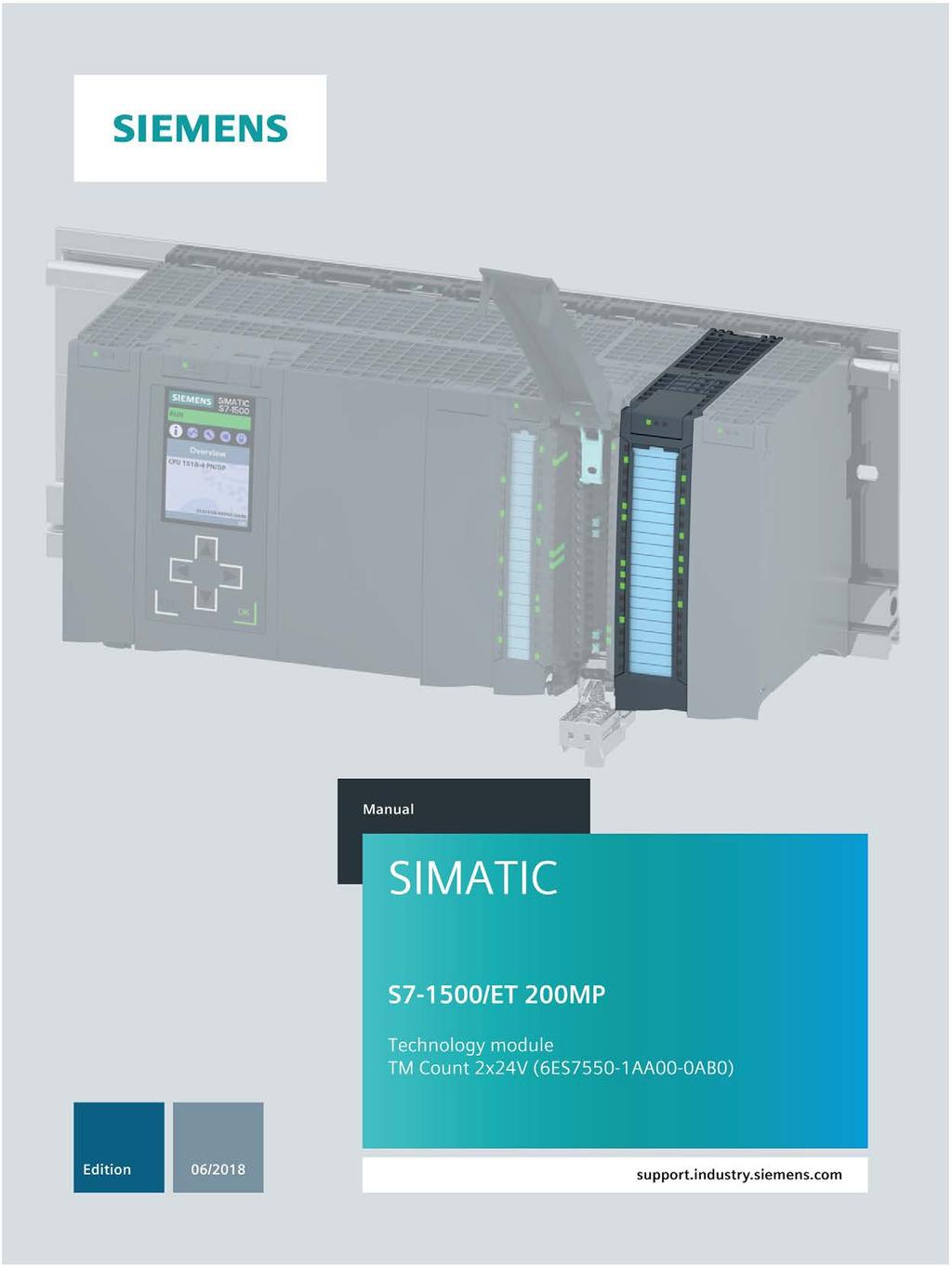
12 Product overview Properties Article number 6ES7550-1AA00-0AB0 Firmware version This manual describes the properties of the module with firmware version V1.3. View of the module Figure 2-1 View of the TM Count 2x24V module Manual, 06/2018, A5E AB 11
13 Product overview 2.1 Properties Properties The TM Count 2x24V technology module has the following properties: Technical properties Two channels Interfaces: 24 V encoder signals A, B and N from sourcing, sinking or push-pull encoders and sensors 24 V encoder supply, short-circuit-proof DI0, DI1 and DI2 digital input signals (per channel) DQ0 and DQ1 digital output signals (per channel) Supply voltage L+ Count range: 32 bits Monitoring of encoder signals for wire break channel by channel Hardware interrupts can be configured channel by channel Input filters for suppression of interferences at encoder inputs and digital inputs can be configured Supported encoder/signal types 24 V incremental encoder with N signal 24 V incremental encoder without N signal 24 V pulse encoder with direction signal 24 V pulse encoder without direction signal 24 V pulse encoder with up/down counting signal Supported system functions Isochronous mode Firmware update Identification data I&M 12 Manual, 06/2018, A5E AB
14 Product overview 2.1 Properties The module supports the following functions: Table 2-1 Version dependencies of the functions Firmware update Function I&M identification data Parameter reassignment in RUN Isochronous mode Counting/measuring Operating with "Counting and measurement" technology object Position input for "Motion Control" technology object Operating with "Measuring input" technology object Position value range of 32 bits Firmware version of module V1.0 or higher V1.0 or higher V1.0 or higher V1.0 or higher V1.0 or higher V1.0 or higher V1.0 or higher V1.3 or higher V1.3 or higher STEP 7 (TIA Portal) Configurable as of PROFINET IO GSD PROFIBUS DP V13 X V13 X X V13 X X V13 V13 X X V13 V13 V15 with HSP0256 V15 with HSP0256 X X Accessories The following components are supplied with the technology module and can also be ordered separately as spare parts: Shield bracket Shield terminal Power supply element Labeling strip U-connector Other components The following component needs to be ordered separately: Front connectors, including potential jumpers and cable ties You can find information on the front connector in system manual S / ET 200MP Automation System ( section "Accessories". Manual, 06/2018, A5E AB 13
15 Product overview 2.2 Functions 2.2 Functions Detection of counting signals Counting is the detecting and adding up of events. The counters of the technology module detect encoder signals and pulses and evaluate them accordingly. The count direction can be specified using encoder or pulse signals or through the user program. You can control the counting processes with the digital inputs. In addition, you can read the signal state of the respective digital input via the feedback interface. You can specify the counter characteristics using the functions described below. Counting limits The counting limits define the counter value range used. The counting limits are configurable and can be modified during runtime with the user program. You can configure the behavior of the counter at the counting limits. Start value You can configure a start value within the counting limits. The start value can be modified during runtime with the user program. Gate control You can define the time window in which the count signals are acquired with the hardware gate (HW gate) and software gate (SW gate). Capture (Latch) You can configure an external reference signal edge that triggers the saving of the current counter value as Capture value. The following external signals can trigger the Capture function: Rising or falling edge of a digital input Both edges of a digital input Rising edge of the N signal at the encoder input The "Frequency of Capture function" parameter specifies whether the function is executed at each configured edge or only once after each enable. Measuring input If you use Position input for Motion Control (Page 16), you can use the "Measuring input" technology object to execute a measuring input function with a hardware digital input. Hardware interrupts The technology module can trigger a hardware interrupt in the CPU, for example, if a comparison event occurs, in the event of overflow or underflow, in the event of a zero crossing of the counter and/or of a change of count direction (direction reversal). You can specify which events during operation are to trigger a hardware interrupt. 14 Manual, 06/2018, A5E AB
16 Product overview 2.2 Functions Measured value determination The following high-accuracy measurement functions are available (accuracy up to 100 ppm): Frequency measurement with the unit of hertz Period measurement with the unit of seconds Velocity measurement with a flexibly adaptable unit Update time You can configure the interval at which the technology module updates the measured values cyclically as the update time. Gate control You can define the time window in which the count signals are acquired with the hardware gate (HW gate) and software gate (SW gate) Switching the outputs at comparison values The available digital outputs DQ0 and DQ1 can be directly activated/switched by the specified comparison values or via the user program. The comparison values are configurable and can be modified during runtime with the user program. This enables very fast reaction times to be achieved. Comparison values in the Counting mode You define two comparison values in the Counting mode. If the current counter value meets the configured comparison condition, the corresponding digital output can be set to directly initiate control processes in the process. Comparison values in the Measuring mode You define two comparison values in the Measuring mode. If the current measured value meets the configured comparison condition, the corresponding digital output can be set to directly initiate control processes in the process. Manual, 06/2018, A5E AB 15
17 Product overview 2.2 Functions Position input for Motion Control You can use the technology module for position detection for the following axis technology objects of S Motion Control : TO_PositioningAxis TO_SynchronousAxis TO_ExternalEncoder In this operating mode, you can use the measuring input technology object (TO_MeasuringInput) to execute a measuring input function with hardware digital input DI1. Additional information You can find a detailed description of the use of Motion Control and its configuration in the following: Function manual S Motion Control available for download on the Internet ( Function manual S7-1500T Motion Control available for download on the Internet ( Additional functions Synchronization You can configure the edge of an external reference signal that loads the counter with the specified start value. The following external signals can trigger a synchronization: Rising or falling edge of a digital input Rising edge of signal N at the encoder input Rising edge of signal N at the encoder input depending on the level of the assigned digital input The "Frequency of synchronization" parameter specifies whether the function is executed at each configured edge or only once after each enable. Hysteresis You can specify a hysteresis for the comparison values within which a digital output will be prevented from switching again. Diagnostic interrupt The technology module can trigger diagnostic interrupts. You enable the diagnostic interrupts in the device configuration. 16 Manual, 06/2018, A5E AB
18 Product overview 2.2 Functions Input filter To suppress interference, you can configure an input filter for the 24 V encoder inputs and for the digital inputs. Isochronous mode The technology module supports the "Isochronous mode" system function. This system function enables counter values and measured values to be acquired in a defined system cycle. Manual, 06/2018, A5E AB 17

19 Wiring Pin assignment and block diagram You connect the encoder signals, the digital input and output signals and the encoder supplies to the 40-pin front connector of the technology module. In addition, you connect the supply voltage for supplying the module and digital outputs and for producing the encoder supply voltages to the 4-pin power supply element. You can find the pin assignment of the front connector and the power supply element in the following two sections. You can find information on wiring the front connector, shielding the cable, etc., in system manual S / ET 200MP Automation System ( section Wiring. Supply voltage L+/M You connect the supply voltage to terminals L+ (terminal 41/42) and M (terminal 43/44). An internal protection circuit protects the technology module from reverse polarity of the supply voltage. The technology module monitors whether the supply voltage is connected. Pin assignment for the power supply element The power supply element is plugged onto the front connector and serves to supply the technology module. For this, you must connect the supply voltage to terminal 41 (L+) and terminal 44 (M). Use terminal 42 (L+) and terminal 43 (M) to loop the supply voltage through to the next module. Figure 3-1 Connection of power supply element L+ Supply voltage 24 V DC M Ground for supply voltage Encoder supply For supplying the encoders and sensors connected to the digital inputs, the technology module provides a 24 V DC supply voltage at output 24VDC (terminal 9) with reference to M (terminal 10). The voltage is monitored for short-circuit and overload. 18 Manual, 06/2018, A5E AB
20 Wiring 3.1 Pin assignment and block diagram Digital inputs DI0, DI1 and DI2 The digital inputs are used for gate control, synchronization and the Capture function. The digital inputs of the two counter channels are not isolated from one another. Input delay for digital inputs In order to suppress signal noise you can configure an input delay for the digital inputs. Note If you select the "None" or "0.05 ms" option, you must use shielded cables for connection of the digital inputs. Digital outputs DQ0 and DQ1 The digital outputs of the two counter channels are not isolated from one another. The digital outputs are 24 V sourcing outputs in reference to M and can carry a rated load current of 0.5 A. They are protected against overload and short-circuit. Relays and contactors can be directly connected without an external protective circuit. You can find information on the maximum possible operating frequencies and the inductance values of the inductive loads connected to the digital outputs in section Technical specifications (Page 61). 24 V encoder signals/count signals The 24 V encoder signals are designated with the letters A, B and N. You can connect the following encoder types: Incremental encoder with N signal: The A, B and N signals are connected using the correspondingly marked terminals. The A and B signals are the two 90 phase-shifted incremental signals. N is the zero mark signal that supplies one pulse per revolution. Incremental encoder without N signal: The A and B signals are connected using the correspondingly marked terminals. The A and B signals are the two 90 phase-shifted incremental signals. The N terminal remains unconnected. Pulse encoder without direction signal: The counting signal is connected to the A terminal. The count direction can be specified via the control interface. The B and N terminals remain unconnected. Manual, 06/2018, A5E AB 19
21 Wiring 3.1 Pin assignment and block diagram Pulse encoder with direction signal: The counting signal is connected to the A terminal. The direction signal is connected to the B terminal. Counting down takes place at a high level of the direction signal. The N terminal remains unconnected. Pulse encoder with up/down counting signal: The up count signal is connected to the A terminal. The down counting signal is connected to the B terminal. The N terminal remains unconnected. The inputs of the two counter channels are not isolated from each other. The inputs are isolated from the backplane bus. You can connect the following encoders or sensors to the A, B and N inputs: Sourcing output: The A, B and N inputs are switched by the encoder or sensor to 24VDC. Sinking output: The A, B and N inputs are switched by the encoder or sensor to ground M. Push-pull: The A, B and N inputs are switched by the encoder or sensor alternately to 24VDC and ground M. Monitoring for wire break is possible with this type of encoder/sensor. The procedure of the wire break detection (alternate switching) requires that, in the event of a fault (wire break), the count can also change without a counting pulse until the wire break is detected. 20 Manual, 06/2018, A5E AB

22 Wiring 3.1 Pin assignment and block diagram Pin assignment for the front connector The table below shows the pin assignment of the front connector. Table 3-1 Pin assignment of the front connector View Signal name Designation Counter channel 0 24 V incremental encoder 24 V pulse encoder with signal N without signal N with direction signal without direction signal Up/ Down 1 CH0.A Encoder signal A Counting signal A Up counting signal A 2 CH0.B Encoder signal B Direction signal B 3 CH0.N Encoder signal N 4 DI0.0 Digital input DI0 5 DI0.1 Digital input DI1 6 DI0.2 Digital input DI2 7 DQ0.0 Digital output DQ0 8 DQ0.1 Digital output DQ1 Encoder supply and ground of the two counter channels 9 24VDC Encoder supply 24 V DC Down counting signal B 10 M Ground for encoder supply, digital inputs and digital outputs Counter channel 1 11 CH1.A Encoder signal A Counting signal A Up counting signal A 12 CH1.B Encoder signal B Direction signal B 13 CH1.N Encoder signal N 14 DI1.0 Digital input DI0 15 DI1.1 Digital input DI1 16 DI1.2 Digital input DI2 17 DQ1.0 Digital output DQ0 18 DQ1.1 Digital output DQ Down counting signal B Manual, 06/2018, A5E AB 21
23 Wiring 3.1 Pin assignment and block diagram Block diagram You must ground the shields of the cables between encoder and technology module both through the shield support at the front connector (shield bracket and terminal) and at the encoder. The figure below shows the block diagram of the technology module with two connected incremental encoders Electrical isolation Shield support at the front connector Technology and backplane bus interface Input filter Supply voltage via power supply element Equipotential bonding Incremental encoder Figure 3-2 Block diagram with two incremental encoders 22 Manual, 06/2018, A5E AB
24 Configuring/address space Operating with "Counting and measurement" technology object Configuring Introduction You configure the technology module and assign its parameters with STEP 7 (TIA Portal). The technology object is used to control and monitor the functions of the technology module. System environment The technology module can be used in the following system environments: Applications Components required Configuration software In the user program Central operation S automation system STEP 7 (TIA Portal): High_Speed_Counter with an S CPU instruction TM Count 2x24V Device configuration with hardware configuration Distributed operation with an S CPU S automation system ET 200MP distributed I/O system TM Count 2x24V Parameter setting with High_Speed_Counter technology object Additional information You can find a detailed description of the counting and measurement functions and their configuration in the following: Function manual Counting, Measurement and Position Detection available for download on the Internet ( Information system of STEP 7 (TIA Portal) under "Using technology functions > Counting, measurement and position input > Counting, measurement and position input (S7-1500)" You can find a detailed description of the use of Motion Control and its configuration in the following: Manual, 06/2018, A5E AB 23
25 Configuring/address space 4.1 Operating with "Counting and measurement" technology object Hardware Support Packages (HSP) If firmware version V1.3 of the module is not yet integrated in your TIA Portal Version V15, you can integrate a corresponding module using HSP0256. You can find the Hardware Support Packages (HSP) for download on the Internet ( You can also access this download from the menu bar of STEP 7 (TIA Portal): "Options > Support packages > Download from the Internet" Reaction to CPU STOP You set the reaction of the technology module to a STOP of the CPU on a channel-bychannel basis in the basic parameters of the device configuration. Table 4-1 Reaction of technology module to CPU STOP Option Continue operation Output substitute value Keep last value Meaning The technology module remains fully functional. Incoming count pulses are processed. The digital outputs continue to switch according to the parameter assignment. The technology module outputs the configured substitute values at the digital outputs until the next CPU STOP-RUN transition. The technology module is returned to its startup state after a STOP-RUN transition: The counter value is set to the start value and the digital outputs switch according to the parameter assignment. The technology module outputs the values at the digital outputs that were valid when the transition to STOP took place until the next CPU STOP-RUN transition. If a digital output with the "At comparison value for a pulse duration" function is set at CPU STOP, the digital output is reset after the pulse duration elapses. The technology module is returned to its startup state after a STOP-RUN transition: The counter value is set to the start value and the digital outputs switch according to the parameter assignment. 24 Manual, 06/2018, A5E AB
26 Configuring/address space 4.1 Operating with "Counting and measurement" technology object Parameter setting You specify the properties of the technology module using various parameters. Depending on the settings, not all parameters are available. When parameters are assigned in the user program, the parameters are transferred to the module with the "WRREC" instruction and data record 128 (Page 71). You set the parameters of the module as follows in this operating mode: 1. Insert the module from the hardware catalog under "Technology modules". 2. Set the device configuration in the hardware configuration. "Operating with "Counting and measurement" technology object" must be set as the operating mode. 3. Insert the High_Speed_Counter technology object from the project tree in folder "Technology objects > Add new object > Counting and measurement". You can find information on configuring with a technology object in function manual Counting, measurement and position detection ( 4. Open the configuration of the High_Speed_Counter technology object, e.g. using the Configuration button in the instruction for the technology object. 5. Set the parameters of the technology object. 6. Download the project to the CPU. Note The "Operating with "Counting and measurement" technology object" and "Manual operation (without technology object)" operating modes apply to one channel in each case. As a result, you can also use a module with both operating modes. Manual, 06/2018, A5E AB 25
27 Configuring/address space 4.1 Operating with "Counting and measurement" technology object Parameters of the TM Count 2x24V The following parameter settings are possible in the hardware configuration: Table 4-2 Settable parameters and their default setting Parameter Value range Default setting Parameter reassignment in RUN Reaction to CPU STOP Output substitute value Keep last value Continue operation Output substitute value Yes Scope HSP for STEP 7 (TIA Portal) Channel Enable diagnostic interrupt on wire break Enable additional diagnostic interrupts Hardware interrupt: New Capture value available Hardware interrupt: Synchronization of the counter by an external signal Hardware interrupt: Gate start Hardware interrupt: Gate stop Hardware interrupt: Overflow (high counting limit violated) Hardware interrupt:underflow (low counting limit violated) Hardware interrupt: Direction reversal Hardware interrupt: Zero crossing Hardware interrupt: Comparison event for DQ0 occurred Hardware interrupt: Comparison event for DQ1 occurred Deactivated Activated Deactivated Activated Deactivated Activated Deactivated Activated Deactivated Activated Deactivated Activated Deactivated Activated Deactivated Activated Deactivated Activated Deactivated Activated Deactivated Activated Deactivated Activated Deactivated Yes Channel Deactivated Yes Channel Deactivated Yes Channel Deactivated Yes Channel Deactivated Yes Channel Deactivated Yes Channel Deactivated Yes Channel Deactivated Yes Channel Deactivated Yes Channel Deactivated Yes Channel Deactivated Yes Channel Deactivated Yes Channel 26 Manual, 06/2018, A5E AB
28 Configuring/address space 4.1 Operating with "Counting and measurement" technology object The following parameter settings are possible in the technology object: Table 4-3 Settable parameters and their default setting Parameter Value range Default setting Parameter reassignment in RUN Signal type Pulse (A) Pulse (A) and direction (B) Count up (A), count down (B) Incremental encoder (A, B phaseshifted) Incremental encoder (A, B, N) Pulse (A) and direction (B) Yes Scope HSP for STEP 7 (TIA Portal) Channel Signal evaluation for counter inputs Invert direction (counter inputs) Filter frequency for counter inputs Single Double Quadruple Deactivated Activated 100 Hz 200 Hz 500 Hz 1 khz 2 khz 5 khz 10 khz 20 khz 50 khz 100 khz 200 khz Single Yes Channel Deactivated Yes Channel 200 khz Yes Channel Sensor type Sourcing output Sourcing output Yes Channel Sinking output Push-pull (sinking and sourcing output) Reaction to signal N No reaction to signal N Synchronization at signal N No reaction to signal N Yes Channel Capture at signal N Frequency of synchronization Frequency of Capture function Once Periodic Once Periodic Once Yes Channel Once Yes Channel Manual, 06/2018, A5E AB 27
29 Configuring/address space 4.1 Operating with "Counting and measurement" technology object Parameter Value range Default setting Parameter reassignment in RUN Counting high limit Yes Channel Start value Yes Channel Counting low limit Yes Channel Reaction to violation of a Stop counting counting limit Continue counting Continue counting Yes Channel Scope HSP for STEP 7 (TIA Portal) Reset when counting limit is violated To opposite counting limit To start value To opposite counting limit Yes Channel Reaction to gate start Set to start value Continue with current value Continue with current value Yes Channel Set function of DI Gate start/stop (level-triggered) Gate start (edge-triggered) Gate stop (edge-triggered) Synchronization Enable synchronization at signal N Capture Digital input without function DI0: Gate start/stop (level-triggered) DI1: Digital input without function DI2: Digital input without function Yes Channel Input delay for digital inputs None 0.1 ms Yes Channel 0.05 ms 0.1 ms 0.4 ms 0.8 ms 1.6 ms 3.2 ms 12.8 ms 20 ms Edge selection for DI At rising edge At rising edge Yes Channel At falling edge At rising and falling edge Select level for DI Active with high level Active with low level Active with high level Yes Channel Behavior of counter value after Capture with DI Continue counting Set to start value and continue counting Continue counting Yes Channel Comparison value Yes Channel Comparison value Yes Channel 28 Manual, 06/2018, A5E AB
30 Configuring/address space 4.1 Operating with "Counting and measurement" technology object Parameter Value range Default setting Parameter reassignment in RUN Operating mode Use count value as reference Use measured value as reference Use count value as reference No Scope HSP for STEP 7 (TIA Portal) Channel Set output Use by user program DQ0, DQ1: Yes Channel Between comparison value and high limit / measured value >= comparison value Between comparison value and high limit Between comparison value and low limit / measured value <= comparison value At comparison value for a pulse duration After set command from CPU until comparison value Between comparison value 0 and 1 Not between comparison value 0 and 1 Count direction of DQ function Up Down In both directions In both directions Yes Channel Pulse duration [ms/10] (corresponds to 0.5 s) Yes Channel Substitute value for DQ0 0 0 Yes Channel 1 Substitute value for DQ1 0 0 Yes Channel 1 Hysteresis (in increments) Yes Channel Measured variable Frequency Frequency Yes Channel Period Velocity Update time [ms] of measuring function Time base for velocity measurement Yes Channel 1 ms 60 s Yes Channel 10 ms 100 ms 1 s 60 s Increments per unit Yes Channel Manual, 06/2018, A5E AB 29
31 Configuring/address space 4.1 Operating with "Counting and measurement" technology object Explanation of parameters You can find a detailed description of the parameters in function manual Counting, Measurement and Position Detection in sections Basic parameters and Configuring the High_Speed_Counter available for download on the Internet ( Address space Address space of the technology module Table 4-4 Size of input and output addresses of the TM Count 2x24V when operating with "Counting and measurement" technology object Inputs Outputs Size per counting channel 16 bytes 12 bytes Total size 32 bytes 24 bytes 30 Manual, 06/2018, A5E AB
32 Configuring/address space 4.1 Operating with "Counting and measurement" technology object Isochronous mode The technology module supports the "Isochronous mode" system function. This system function enables counter values and measured values to be acquired in a defined system cycle. In isochronous mode, the cycle of the user program, the transmission of the input signals and processing in the technology module are synchronized. The output signals switch immediately if the relevant comparison condition is met. A status change of a digital input immediately triggers the specified reaction of the technology module and the change of the status bit of the digital input in the feedback interface. Use an OB of type "Synchronous Cycle" (e.g. OB61) in this operating mode. The High_Speed_Counter instruction is called in the assigned OB. The update time for the measured value is synchronized with the system cycle in a suitable ratio and, if necessary, adapted in length. If you set "0", the measured value is updated once per system cycle. Data processing The data that was transmitted to the technology module in the current bus cycle via the control interface takes effect when it is processed in the internal technology module cycle. At the time the input data is read in (Ti), the counter value and the measured value as well as status bits are acquired and made available in the feedback interface for retrieval in the current bus cycle. Isochronous mode parameters In isochronous mode, the "Filter frequency" parameter can affect the isochronous mode parameters of the sync domain. Because the isochronous mode parameters are not checked in RUN, overflows can occur if you change the parameters in RUN. To prevent overflows, select the option with the largest time required in the offline parameter assignment. Additional information You can find a detailed description of isochronous mode in the following: Function manual Isochronous Mode (STEP 7 (TIA Portal) V15.1 or higher) available for download on the Internet ( Function manual PROFINET with STEP 7 available for download on the Internet ( Manual, 06/2018, A5E AB 31
33 Configuring/address space 4.2 Position input for "Motion Control" technology object 4.2 Position input for "Motion Control" technology object Configuring Introduction You configure the technology module and assign its parameters with STEP 7 (TIA Portal). The technology object is used to control and monitor the functions of the technology module. System environment The technology module can be used in the following system environments: Applications Components required Configuration software In the user program Central operation S automation system STEP 7 (TIA Portal): Motion Control instructions with an S CPU TM Count 2x24V Device configuration with hardware configuration Distributed operation with an S CPU S automation system ET 200MP distributed I/O system TM Count 2x24V Parameter setting with axis and measuring input technology objects Additional information You can find a detailed description of the use of Motion Control and its configuration in the following: Function manual S Motion Control available for download on the Internet ( Function manual S7-1500T Motion Control available for download on the Internet ( Information system of STEP 7 (TIA Portal) under "Using technology functions > Motion Control > Motion Control (S7-1200, S7-1500)" You can find a description of configuring the technology module for position detection in the following: Function manual Counting, Measurement and Position Detection available for download on the Internet ( Information system of STEP 7 (TIA Portal) under "Using technology functions > Counting, measurement and position input > Counting, measurement and position input (S7-1500)" Hardware Support Packages (HSP) If firmware version V1.3 of the module is not yet integrated in your TIA Portal Version V15, you can integrate a corresponding module using HSP0256. You can find the Hardware Support Packages (HSP) for download on the Internet ( You can also access this download from the menu bar of STEP 7 (TIA Portal): "Options > Support packages > Download from the Internet". 32 Manual, 06/2018, A5E AB
34 Configuring/address space 4.2 Position input for "Motion Control" technology object Parameter setting You specify the properties of the technology module using various parameters. Depending on the settings, not all parameters are available. You set the parameters of the module as follows in this operating mode: 1. Insert the module from the hardware catalog under "Technology modules". 2. Set the device configuration and the parameters of the module in the hardware configuration. "Position input for "Motion Control" technology object" must be set as the operating mode. 3. Insert the axis technology object and, if necessary, the measuring input technology object from the project tree in folder "Technology objects > Add new object > Motion Control". You can find information on configuring with axis technology objects in function manual S7-1500T Motion Control ( 4. Open the configuration of the axis technology object, e.g. using the Configuration button in the respective instruction for the technology object. 5. Set the parameters of the technology objects. 6. Download the project to the CPU. Note This operating mode applies automatically to both channels of the technology module. Parameters of the TM Count 2x24V The following parameter settings are possible: Table 4-5 Settable parameters and their default setting Parameter Value range Default setting Scope Signal type Pulse (A) Pulse (A) and direction (B) Count up (A), count down (B) Incremental encoder (A, B phaseshifted) Incremental encoder (A, B, N) Pulse (A) and direction (B) HSP for STEP 7 (TIA Portal) Channel Invert direction (counter inputs) Deactivated Activated Deactivated Channel Signal evaluation for counter inputs Single Double Single Channel Quadruple Manual, 06/2018, A5E AB 33
35 Configuring/address space 4.2 Position input for "Motion Control" technology object Parameter Value range Default setting Scope Filter frequency for counter inputs 100 Hz 200 Hz 500 Hz 1 khz 2 khz 5 khz 10 khz 20 khz 50 khz 100 khz 200 khz HSP for STEP 7 (TIA Portal) 200 khz Channel Sensor type Sourcing output Sinking output Push-pull (sinking and sourcing output) Sourcing output Channel Signal selection for reference mark 0 DI0 Signal N of incremental encoder DI0 Channel Measuring input DI1 DI1 Channel Increments per revolution / Channel steps per revolution Reference speed U/min U/min Channel Enable diagnostic interrupt on Deactivated wire break Activated Deactivated Channel Enable additional diagnostic interrupts Deactivated Activated Deactivated Channel Explanation of parameters You can find a detailed description of the parameters in function manual Counting, Measurement and Position Detection, section Module parameters (position input for Motion Control) available for download on the Internet ( 34 Manual, 06/2018, A5E AB
36 Configuring/address space 4.2 Position input for "Motion Control" technology object Address space Address space of the technology module Table 4-6 Size of input and output addresses of the TM Count 2x24V with position input for "Motion Control" technology object Inputs Outputs Size per counting channel 16 bytes 4 bytes Total size 32 bytes 8 bytes Isochronous mode The technology module supports the "Isochronous mode" system function. Counter values can be acquired in a fixed system cycle with this system function. In isochronous mode, the cycle of the user program, the transmission of the input signals and processing in the technology module are synchronized. A status change of a digital input immediately triggers the specified reaction of the technology module and the change of the status bit of the digital input in the feedback interface. Use an OB of type "MC-Servo" in this operating mode. Isochronous mode is needed when using the output cam and cam track technology objects. When the measuring input technology is used in combination with hardware digital input DI1, isochronous mode is not needed. Data processing The data that was transmitted to the technology module in the current bus cycle via the control interface takes effect when it is processed in the internal technology module cycle. At the time the input data is read in (Ti), the counter value and the status bits are acquired and made available in the feedback interface for retrieval in the current bus cycle. Isochronous mode parameters In isochronous mode, the "Filter frequency" parameter can affect the isochronous mode parameters of the sync domain. Because the isochronous mode parameters are not checked in RUN, overflows can occur if you change the parameters in RUN. To prevent overflows, select the option with the largest time required in the offline parameter assignment. Additional information You can find a detailed description of isochronous mode in the following: Function manual Isochronous Mode (STEP 7 (TIA Portal) V15.1 or higher) available for download on the Internet ( Function manual PROFINET with STEP 7 available for download on the Internet ( Manual, 06/2018, A5E AB 35
37 Configuring/address space 4.3 Manual operation (without technology object) 4.3 Manual operation (without technology object) Configuring Introduction You configure the technology module and assign its parameters with the configuration software. The functions of the technology module are controlled and checked by the user program via the control and feedback interface. System environment The technology module can be used in the following system environments: Applications Components required Configuration software In the user program Central operation S automation system STEP 7 (TIA Portal): Direct access to control with an S CPU and feedback interface in TM Count 2x24V Device configuration and the I/O data parameter setting with hardware configuration Distributed operation with an S CPU Distributed operation with an S7-300/400 CPU Distributed operation with an S CPU Distributed operation in a third-party system S automation system ET 200MP distributed I/O system TM Count 2x24V S7-300/400 or S automation system ET 200MP distributed I/O system TM Count 2x24V S7-300/400 or S automation system ET 200MP distributed I/O system TM Count 2x24V Third-party automation system ET 200MP distributed I/O system TM Count 2x24V STEP 7 (TIA Portal): Device configuration and parameter setting with hardware configuration STEP 7 (TIA Portal): Device configuration and parameter setting with hardware configuration STEP 7: Device configuration and parameter setting with GSD file STEP 7 (TIA Portal): Device configuration and parameter setting with hardware configuration Third-party configuration software: Device configuration and parameter setting with GSD file 36 Manual, 06/2018, A5E AB
38 Configuring/address space 4.3 Manual operation (without technology object) Additional information You can find a detailed description of the counting and measurement functions and their configuration in the following: Function manual Counting, Measurement and Position Detection available for download on the Internet ( Information system of STEP 7 (TIA Portal) under "Using technology functions > Counting, measurement and position input > Counting, measurement and position input (S7-1500)" Hardware Support Packages (HSP) If firmware version V1.3 of the module is not yet integrated in your TIA Portal Version V15, you can integrate a corresponding module using HSP0256. You can find the Hardware Support Packages (HSP) for download on the Internet ( You can also access this download from the menu bar of STEP 7 (TIA Portal): "Options > Support packages > Download from the Internet". GSD file You can find the respective GSD file for the ET 200SP distributed I/O system for download on the Internet: GSD file for PROFINET IO ( GSD file for PROFIBUS DP ( Manual, 06/2018, A5E AB 37
39 Configuring/address space 4.3 Manual operation (without technology object) Reaction to CPU STOP You set the reaction of the technology module to a STOP of the CPU on a channel-bychannel basis in the basic parameters of the device configuration. Table 4-7 Reaction of technology module to CPU STOP Option Continue operation Output substitute value Keep last value Meaning The technology module remains fully functional. Incoming count pulses are processed. The digital outputs continue to switch according to the parameter assignment. The technology module outputs the configured substitute values at the digital outputs until the next CPU STOP-RUN transition. The technology module is returned to its startup state after a STOP-RUN transition: The counter value is set to the start value and the digital outputs switch according to the parameter assignment. The technology module outputs the values at the digital outputs that were valid when the transition to STOP took place until the next CPU STOP-RUN transition. If a digital output with the "At comparison value for a pulse duration" function is set at CPU STOP, the digital output is reset after the pulse duration elapses. The technology module is returned to its startup state after a STOP-RUN transition: The counter value is set to the start value and the digital outputs switch according to the parameter assignment. 38 Manual, 06/2018, A5E AB
40 Configuring/address space 4.3 Manual operation (without technology object) Parameter setting You specify the properties of the technology module using various parameters. Depending on the settings, not all parameters are available. When parameters are assigned in the user program, the parameters are transferred to the module with the "WRREC" instruction and data record 128 (Page 71). You set the parameters of the module as follows in this operating mode: Parameter setting using... Hardware configuration in STEP 7 (TIA Portal) Hardware configuration with GSD file for distributed operation on PROFINET IO Hardware configuration with GSD file for distributed operation on PROFIBUS DP Basic procedure 1. Insert the module from the hardware catalog under "Technology modules". 2. Set the device configuration and the parameters of the module in the hardware configuration. "Manual operation (without technology object)" must be set as the operating mode. 3. Download the project to the CPU. 1. Install the current PROFINET GSD file. You will then find the module in the hardware catalog under "Other field devices > PROFINET IO > I/O". 2. Set the parameters in the hardware configuration. You can find information on the respective dependencies of the parameters in function manual Counting, Measurement and Position Detection ( 3. Download the project to the CPU. 1. Install the current PROFIBUS GSD file. You will then find the module in the hardware catalog under "Other field devices > PROFIBUS DP > I/O". 2. Set the parameters in the hardware configuration. You can find information on the respective dependencies of the parameters in function manual Counting, Measurement and Position Detection ( The parameters marked with 1 in the following tables are not configurable in the PROFIBUS GSD file. 3. Download the project to the CPU. The parameters marked with 1 in the following tables are downloaded with their default setting. 4. If necessary, set the parameters marked with 1 in the user program using data record 128. Note The "Operating with "Counting and measurement" technology object" and "Manual operation (without technology object)" operating modes apply to one channel in each case. As a result, you can also use a module with both operating modes. Manual, 06/2018, A5E AB 39
41 Configuring/address space 4.3 Manual operation (without technology object) Parameters of the TM Count 2x24V The following parameter settings are possible: Table 4-8 Settable parameters and their default setting Parameter Value range Default setting Parameter reassignment in RUN Operating mode 3 Counting Measuring Counting No Channel Scope HSP for STEP 7 (TIA Portal); GSD file Reaction to CPU STOP 1 Output substitute value Keep last value Output substitute value Yes Channel Continue operation Substitute value for DQ Yes Channel 1 Substitute value for DQ Yes Channel Enable diagnostic interrupt on wire break 2 Enable additional diagnostic interrupts Hardware interrupt: New Capture value available 1 Hardware interrupt: Synchronization of the counter by an external signal 1 Hardware interrupt: Gate start 1 Hardware interrupt: Gate stop 1 Hardware interrupt: Overflow (high counting limit violated) 1 Hardware interrupt:underflow (low counting limit violated) 1 Hardware interrupt: Direction reversal 1 Hardware interrupt: Zero crossing 1 1 Deactivated Activated Deactivated Activated Deactivated Activated Deactivated Activated Deactivated Activated Deactivated Activated Deactivated Activated Deactivated Activated Deactivated Activated Deactivated Activated Deactivated Yes Channel Deactivated Yes Channel Deactivated Yes Channel Deactivated Yes Channel Deactivated Yes Channel Deactivated Yes Channel Deactivated Yes Channel Deactivated Yes Channel Deactivated Yes Channel Deactivated Yes Channel 40 Manual, 06/2018, A5E AB
42 Configuring/address space 4.3 Manual operation (without technology object) Parameter Value range Default setting Parameter reassignment in RUN Hardware interrupt: Comparison event for DQ0 oc- Deactivated curred 1 Activated Hardware interrupt: Comparison event for DQ1 oc- Deactivated curred 1 Activated Signal type Pulse (A) Pulse (A) and direction (B) Count up (A), count down (B) Incremental encoder (A, B phase-shifted) Incremental encoder (A, B, N) Deactivated Yes Channel Deactivated Yes Channel Pulse (A) and direction (B) Yes Scope HSP for STEP 7 (TIA Portal); GSD file Channel Invert direction (counter inputs) 1 Signal evaluation for counter inputs Filter frequency for counter inputs 1 Deactivated Activated Single Double Quadruple 100 Hz 200 Hz 500 Hz 1 khz 2 khz 5 khz 10 khz 20 khz 50 khz 100 khz 200 khz Deactivated Yes Channel Single Yes Channel 200 khz Yes Channel Sensor type Sourcing output Sourcing output Yes Channel Sinking output Push-pull (sinking and sourcing output) Reaction to signal N 1 No reaction to signal N Synchronization at signal N No reaction to signal N Yes Channel Capture at signal N Frequency of synchronization 1 Once Periodic Once Yes Channel Manual, 06/2018, A5E AB 41
43 Configuring/address space 4.3 Manual operation (without technology object) Parameter Value range Default setting Parameter reassignment in RUN Frequency of Capture function 1 Once Periodic Once Yes Channel High counting limit Yes Channel Start value Yes Channel Counting low limit Yes Channel Reaction to violation of a Stop counting counting limit Continue counting Continue counting Yes Channel Scope HSP for STEP 7 (TIA Portal); GSD file Reset when counting limit is violated To opposite counting limit To start value To opposite counting limit Yes Channel Reaction to gate start Set to start value Continue with current value Continue with current value Yes Channel Set function of DI Gate start/stop (leveltriggered) Gate start (edge-triggered) Gate stop (edge-triggered) Synchronization Enable synchronization at signal N DI0: Gate start/stop (leveltriggered) DI1: Digital input without function DI2: Digital input without function Yes Channel Capture Digital input without function Select level for DI 1 Active with high level Active with low level Active with high level Yes Channel Edge selection for DI 1 At rising edge At rising edge Yes Channel Behavior of counter value after Capture with DI 1 At falling edge At rising and falling edge Continue counting Set to start value and continue counting Continue counting Yes Channel 42 Manual, 06/2018, A5E AB
44 Configuring/address space 4.3 Manual operation (without technology object) Parameter Value range Default setting Parameter reassignment in RUN Input delay for digital inputs 1 None 0.05 ms 0.1 ms 0.4 ms 0.8 ms 1.6 ms 3.2 ms 12.8 ms 20 ms 0.1 ms Yes Channel Scope HSP for STEP 7 (TIA Portal); GSD file Set output Use by user program DQ0, DQ1: Yes Channel Between comparison value and high limit / measured value >= comparison value Between comparison value and high limit Between comparison value and low limit / measured value <= comparison value At comparison value for a pulse duration After set command from CPU until comparison value Between comparison value 0 and 1 Not between comparison value 0 and 1 Comparison value Yes Channel Comparison value Yes Channel Count direction of DQ function Down Up In both directions In both directions Yes Channel Pulse duration [ms/10] (corresponds Yes Channel to 0.5 s) Hysteresis (in increments) Yes Channel Measured variable Frequency Frequency Yes Channel Period Velocity Update time [ms] of the measuring function Yes Channel Manual, 06/2018, A5E AB 43
45 Configuring/address space 4.3 Manual operation (without technology object) Parameter Value range Default setting Parameter reassignment in RUN Time base for velocity measurement 1 1 ms 10 ms 100 ms 1 s 60 s 60 s Yes Channel Increments per unit Yes Channel Scope HSP for STEP 7 (TIA Portal); GSD file 1 Because the number of parameters is limited to a maximum of 244 bytes per station in the PROFIBUS GSD configuration, the possible parameter assignments are limited. The parameters are preassigned default settings in the module. If your PROFIBUS master supports the "Write/read data record" function, you can set these parameters using data record When a GSD file is used, this diagnostic interrupt is enabled with the "Enable additional diagnostic interrupts" parameter and is then not separately configurable. 3 When configuring with a GSD file, you determine the operating mode when you select the module name. Explanation of parameters You can find a detailed description of the parameters in function manual Counting, Measurement and Position Detection, sections Basic parameters and Manual operation available for download on the Internet ( Address space Address space of the technology module Table 4-9 Size of input and output addresses of the TM Count 2x24V with manual operation Inputs Outputs Size per counting channel 16 bytes 12 bytes Total size 32 bytes 24 bytes 44 Manual, 06/2018, A5E AB
46 Configuring/address space 4.3 Manual operation (without technology object) Control and feedback interface Note The control and feedback interface is compatible with the control and feedback interface of the TM Count 1x24V, TM PosInput 2 and TM PosInput 1 technology modules of the S automation system Assignment of the control interface The user program uses the control interface to influence the behavior of the technology module. Control interface per channel The following table shows the assignment of the control interface: Byte offset from start address Channel 0/1 Bit 7 Bit 6 Bit 5 Bit 4 Bit 3 Bit 2 Bit 1 Bit SLOT_0: DINT or REAL: Load value (meaning of the value is specified in LD_SLOT_0) 3 15 Value range: to D or to 7FFFFFFFH 4 16 SLOT_1: DINT or REAL: Load value (meaning of the value is specified in LD_SLOT_1) 7 19 Value range: to D or to 7FFFFFFFH 8 20 LD_SLOT_1 LD_SLOT_ EN_ CAPTURE EN_ SYNC_DN EN_ SYNC_UP SET_DQ1 SET_DQ0 TM_ CTRL_DQ1 TM_ CTRL_DQ SET_DIR Reserved RES_ EVENT Reserved SW_GATE RES_ ERROR Manual, 06/2018, A5E AB 45
47 Configuring/address space 4.3 Manual operation (without technology object) Explanations Control bit/value EN_CAPTURE EN_SYNC_DN EN_SYNC_UP LD_SLOT_m Explanations Use this bit to enable the Capture function. Resetting this bit resets a set EVENT_CAP in the feedback interface. Use this bit to enable the synchronization of the counter when counting in downward direction with an incremental encoder or pulse encoder. Resetting this bit resets a set EVENT_SYNC in the feedback interface. Use this bit to enable the synchronization of the counter when counting in upward direction with an incremental encoder or pulse encoder. Resetting this bit resets a set EVENT_SYNC in the feedback interface. Use this load request to specify the meaning of the value in SLOT_m: 0000 means: No action, idle 0001 means: Load counter value 0010 not permitted 0011 means: Load start value 0100 means: Load comparison value means: Load comparison value means: Load counting low limit 0111 means: Load counting high limit 1000 to 1111 not permitted The technology module executes the respective action as soon as LD_SLOT_m changes. If values are loaded simultaneously using LD_SLOT_0 and LD_SLOT_1, the value from SLOT_0 is internally applied first and then the value from SLOT_1. This can produce unexpected intermediate states. RES_EVENT Use this bit to trigger the reset of the saved events in the EVENT_ZERO, EVENT_OFLW, EVENT_UFLW, EVENT_CMP0, EVENT_CMP1 feedback bits. RES_ERROR Use this bit to trigger the reset of the saved error states LD_ERROR and ENC_ERROR. Reserved Reserve bits must be set to 0. SET_DIR Use this bit to specify the count direction for signal type "Pulse (A)". 0 means: Up 1 means: Down SET_DQ0 Use this bit to set digital output DQ0 when TM_CTRL_DQ0 is set to 0. In the case of the function "After set command from CPU until comparison value", SET_DQ0 is effective regardless of TM_CTRL_DQ0 as long as the counter value is not equal to the comparison value. SET_DQ1 Use this bit to set digital output DQ1 when TM_CTRL_DQ1 is set to 0. In the case of the function "After set command from CPU until comparison value", SET_DQ1 is effective regardless of TM_CTRL_DQ1 as long as the counter value is not equal to the comparison value. 46 Manual, 06/2018, A5E AB
48 Configuring/address space 4.3 Manual operation (without technology object) Control bit/value SW_GATE Explanations Use this bit to open and close the software gate when using an incremental encoder or pulse encoder. Together, the software gate and the hardware gate form the internal gate. The technology module only counts when the internal gate is open. 0 means: Software gate closed TM_CTRL_DQ0 1 means: Software gate open The digital inputs of the technology module externally control the hardware gate. The hardware gate can be activated by parameter assignment. The software gate cannot be deactivated. Use this bit to enable the technological function of digital output DQ0. 0 means: SET_DQ0 defines the state of DQ0 1 means: assigned function defines the state of DQ0 TM_CTRL_DQ1 Use this bit to enable the technological function of digital output DQ1. 0 means: SET_DQ1 defines the state of DQ1 1 means: assigned function defines the state of DQ1 Manual, 06/2018, A5E AB 47
49 Configuring/address space 4.3 Manual operation (without technology object) Assignment of the feedback interface The user program receives current values and status information from the technology module by means of the feedback interface. Feedback interface per channel The following table shows the assignment of the feedback interface: Byte offset from start address Channel 0/ Bit 7 Bit 6 Bit 5 Bit 4 Bit 3 Bit 2 Bit 1 Bit 0 COUNT_VALUE: DINT: Current counter value CAPTURED_VALUE: DINT: The last acquired Capture value MEASURED_VALUE: REAL: Current measured value Reserved LD_ERROR ENC_ ERROR Reserved STS_ SW_GATE STS_ READY LD_STS_ SLOT_1 LD_STS _SLOT_0 RES _EVENT _ACK POWER_ ERROR Reserved STS_DI2 STS_DI1 STS_DI0 STS_DQ1 STS_DQ0 STS_GATE STS_CNT STS_DIR STS_M_ INTERVAL EVENT_ CAP EVENT_ SYNC EVENT_ CMP1 EVENT_ CMP0 EVENT_ OFLW EVENT_ UFLW EVENT_ ZERO 48 Manual, 06/2018, A5E AB
50 Configuring/address space 4.3 Manual operation (without technology object) Explanations Feedback bit/value Explanations CAPTURED_VALUE This DINT value indicates the last acquired Capture value. The following external signals can trigger the Capture function: Rising or falling edge of a digital input COUNT_VALUE ENC_ERROR Both edges of a digital input The "Frequency of Capture function" parameter specifies whether the function is executed at each configured edge or only once after each enable. This DINT value indicates the current counter value. This bit indicates that one of the following errors has occurred at the encoder signals (retentive) for the respective technology module: Wire break of digital input A, B or N (with push-pull encoder) EVENT_CAP EVENT_CMP0 EVENT_CMP1 EVENT_OFLW EVENT_SYNC EVENT_UFLW EVENT_ZERO LD_ERROR Invalid transition of A/B signals (with incremental encoder) If you have enabled the diagnostic interrupts, the respective diagnostic interrupt is triggered in the event of encoder signal errors. For information on the meaning of the diagnostic interrupts, refer to the manual for the respective technology module. The bit is reset once you have acknowledged the error with RES_ERROR. This bit indicates that a Capture event has occurred and a counter value has been saved in CAPTURED_VALUE. You reset the status by resetting EN_CAPTURE. This bit indicates the saved status that a comparison event (status change) has occurred for the digital output DQ0 based on the selected comparison condition. You reset the status by acknowledgment with RES_EVENT. If the counter value is set to the start value in counting mode, EVENT_CMP0 is not set. This bit indicates the saved status that a comparison event (status change) has occurred for the digital output DQ1 based on the selected comparison condition. You reset the status by acknowledgment with RES_EVENT. If the counter value is set to the start value in counting mode, EVENT_CMP1 is not set. This bit indicates the saved status that the counter value had an overflow. You reset the status by acknowledgment with RES_EVENT. When an incremental or pulse encoder is used, this bit indicates the saved status that the counter was loaded with the start value by an external reference signal (synchronization). You reset the status by resetting EN_SYNC_UP or EN_SYNC_DN. This bit indicates the saved status that the counter value had an underflow. You reset the status by acknowledgment with RES_EVENT. This bit indicates the saved status that the counter value or position value had a zero crossing. You reset the status by acknowledgment with RES_EVENT. When the "Zero crossing" hardware interrupt is enabled, for system-related reasons it can also be triggered if "0" is outside the configured value range. This bit indicates that an error occurred (latching) during loading via the control interface. The loaded values were not applied. When using an incremental or pulse encoder, one of the following conditions is not fulfilled: Low counting limit <= counter value <= high counting limit Low counting limit <= start value <= high counting limit Low counting limit <= comparison value 0/1 <= high counting limit The bit is reset once you have acknowledged the error with RES_ERROR. Manual, 06/2018, A5E AB 49
51 Configuring/address space 4.3 Manual operation (without technology object) Feedback bit/value LD_STS_SLOT_0 Explanations This bit indicates by a status change (toggling) that the load request for SLOT_0 (LD_SLOT_0) was detected and performed. LD_STS_SLOT_1 This bit indicates by a status change (toggling) that the load request for SLOT_1 (LD_SLOT_1) was detected and performed. MEASURED_VALUE This value indicates the current measured value with data type REAL: Frequency: The mean frequency is calculated from the time profile of the count pulses or position value changes in one measurement interval and returned as a floating-point number in the unit of hertz. Period: The mean period is calculated from the time profile of the count pulses or position value changes in one measurement interval and returned as a floating-point number in the unit of seconds. Velocity: The mean velocity is calculated from the time profile of the count pulses or position value changes in one measurement interval and returned as a floating-point number in the configured unit. The measured values are returned as a signed value. The sign indicates whether the counter value went up or down in the relevant time interval. The update time is asynchronous to the opening of the internal gate, i.e. the update time is not started when the gate opens. After the internal gate closes, the last calculated measured value continues to be returned. POWER_ERROR This bit indicates that supply voltage L+ is not present or is too low or the front connector is not inserted. If you have enabled the diagnostic interrupts (Page 56), the diagnostics interrupt "Supply voltage missing" is triggered at a supply voltage error. When supply voltage L+ is available at a sufficient level once again, POWER_ERROR is automatically set to 0. RES_EVENT_ACK This bit indicates that the reset of event bit EVENT_SYNC, EVENT_CMP0, EVENT_CMP1, EVENT_OFLW, EVENT_UFLW, EVENT_ZERO is active. Reserved Reserved bits are set to 0. STS_CNT This bit indicates that at least one count pulse or a position value change has occurred in the last ca. 0.5 s. STS_DI0 This bit indicates the status of digital input DI0. STS_DI1 This bit indicates the status of digital input DI1. STS_DI2 This bit indicates the status of digital input DI2. STS_DIR This bit indicates the count direction of the last count pulse or the direction of the last position value change. 0 means: Down 1 means: Up STS_DQ0 STS_DQ1 STS_GATE This bit indicates the status of digital output DQ0. This bit indicates the status of digital output DQ1. This bit indicates the status of the internal gate when using an incremental or pulse encoder. 0 means: Gate closed 1 means: Gate open STS_M_INTERVAL This bit indicates that at least one count pulse or a position value change was detected in the previous measurement interval. 50 Manual, 06/2018, A5E AB
52 Configuring/address space 4.3 Manual operation (without technology object) Feedback bit/value STS_READY STS_SW_GATE Explanations This bit indicates that the technology module supplies valid user data. The technology module has been started up and configured. This bit indicates the status of the software gate. 0 means: Gate closed 1 means: Gate open Manual, 06/2018, A5E AB 51
53 Configuring/address space 4.3 Manual operation (without technology object) Isochronous mode The technology module supports the "Isochronous mode" system function. This system function enables counter values and measured values to be acquired in a defined system cycle. In isochronous mode, the cycle of the user program, the transmission of the input signals and processing in the technology module are synchronized. The output signals switch immediately if the relevant comparison condition is met. A status change of a digital input immediately triggers the specified reaction of the technology module and the change of the status bit of the digital input in the feedback interface. Use an OB of type "Synchronous Cycle" (e.g. OB61) in this operating mode. The input and output data are processed in the assigned OB. The update time for the measured value is synchronized with the system cycle in a suitable ratio and, if necessary, adapted in length. If you set "0", the measured value is updated once per system cycle. Data processing The data that was transmitted to the technology module in the current bus cycle via the control interface takes effect when it is processed in the internal technology module cycle. At the time the input data is read in (Ti), the counter value and the measured value as well as status bits are acquired and made available in the feedback interface for retrieval in the current bus cycle. Isochronous mode parameters In isochronous mode, the "Filter frequency" parameter can affect the isochronous mode parameters of the sync domain. Because the isochronous mode parameters are not checked in RUN, overflows can occur if you change the parameters in RUN. To prevent overflows, select the option with the largest time required in the offline parameter assignment. Additional information You can find a detailed description of isochronous mode in the following: Function manual Isochronous Mode (STEP 7 (TIA Portal) V15.1 or higher) available for download on the Internet ( Function manual PROFINET with STEP 7 available for download on the Internet ( 52 Manual, 06/2018, A5E AB
 of TM Count")
54 Interrupts/diagnostic messages Status and error display LEDs The following figure shows you the LED displays (status and error displays) of TM Count 2x24V. Figure 5-1 LED displays of the TM Count 2x24V Manual, 06/2018, A5E AB 53
55 Interrupts/diagnostic messages 5.1 Status and error display Meaning of the LED displays The following tables explain the meaning of the status and error displays. Remedial measures for diagnostic alarms can be found in section Diagnostic alarms (Page 56). Table 5-1 Status and error displays RUN/ERROR/MAINT LEDs Meaning Remedy RUN ERROR MAINT Off Off Off Missing or insufficient voltage on the backplane bus Switch on the CPU and/or the system power supply modules. Check whether the U connectors are plugged in correctly. Check whether too many modules are plugged in. Flashes Off Off On Off Off On Flashes Off Flashes Flashes Flashes Technology module parameters not set --- Technology module parameters set and no module diagnostics Technology module parameters set and module diagnostics (at least one error is present) Hardware or firmware defective Evaluate the diagnostic alarms and eliminate the error. Replace the technology module. Table 5-2 PWR/24VDC/ERROR status displays LEDs Meaning Remedy PWR 24VDC ERROR Off Off Off Off Off Flashing 1 On On Off On Off Off On Off Flashing 1 Supply voltage too low or missing Check the supply voltage. Make sure that the front connector is correctly inserted. Supply voltage is present and OK --- Short-circuit or overload at the encoder supply Correct the encoder wiring. Check the loads connected to the encoder supply. Check the supply voltage. 1 Only when diagnostic interrupts enabled 54 Manual, 06/2018, A5E AB
56 Interrupts/diagnostic messages 5.1 Status and error display Channel LEDs The CHn.A, CHn.B, CHn.N and DIn.m LEDs indicate the current level of the associated signals. The LEDs of the DQn.m digital outputs indicate the desired state. The UP and DN LEDs indicate the logical counting direction. The flashing frequency of the channel LEDs is limited to approximately 12 Hz. If higher frequencies are present, the channel LEDs will flash at 12 Hz instead of indicating the current status. Table 5-3 Status displays CHn.m/DIn.m/DQn.m LEDs CHn.m/DIn.m/DQn.m Off On On (CHn.m/DQn.m) Meaning Counter input/digital input/digital output at 0 level Counter input/digital input/digital output at 1 level Diagnostic alarm: e.g. wire break, short-circuit Remedy Check the wiring or the connected load. Table 5-4 Status displays CHn.UP/CHn.DN CHn.UP Off On Off On LEDs CHn.DN Off Off On On Meaning No count pulse has been detected for the last 0.5 s. The last count pulse has incremented the counter and took place no more than 0.5 s ago. The last count pulse has decremented the counter and took place no more than 0.5 s ago. Invalid transition of A/B signals Manual, 06/2018, A5E AB 55
57 Interrupts/diagnostic messages 5.2 Diagnostic alarms 5.2 Diagnostic alarms Enabling of diagnostic interrupts You enable the diagnostic interrupts in the device configuration with the basic parameters. The technology module can trigger the following diagnostic interrupts: Table 5-5 Possible diagnostic interrupts Diagnostic interrupt Parameter error Hardware interrupt lost 1 Internal error Watchdog tripped. Module is defective. Monitoring Monitoring is always active. A diagnostic interrupt is triggered each time an error is detected. Wire break at digital input A, B or N Monitoring is active if a push-pull switching encoder has been configured. When an error is detected, a diagnostic interrupt is only triggered if "Enable diagnostic interrupt on wire break" is activated in the device configuration. Supply voltage missing Short-circuit / overload at external encoder supply Error at digital outputs Supply voltage error 2 Invalid transition of A/B signals Overtemperature Monitoring is always active. When an error is detected, a diagnostic interrupt is only triggered if "Enable additional diagnostic interrupts" is activated in the device configuration. 1 Not available in "Position input for "Motion Control"" technology object" operating mode 2 No longer available as of module version V1.3. This case is then taken into account by the diagnostic interrupt "Supply voltage missing". Reactions to a diagnostic interrupt The following happens when an event occurs that triggers a diagnostic interrupt: The ERROR LED flashes red. Once you have remedied the error, the ERROR LED goes out. The S CPU interrupts processing of the user program. The diagnostic interrupt OB (e.g. OB 82) is called. The event that triggered the interrupt is entered in the start information of the diagnostic interrupt OB. The S CPU remains in RUN even if no diagnostic interrupt OB is present in the CPU. The technology module continues working unchanged if this is possible despite the error. You can obtain detailed information on the error event in the error organization block with instruction "RALRM" (Read additional alarm information), in the information system of STEP 7 and in function manual Diagnostics ( section "System diagnostics in user program". If the module is operated as a distributed module with PROFIBUS DP in an ET 200MP system, you have the option of reading out diagnostic data with the RDREC or RD_REC instruction using data record 0 and 1. You can find the structure of the data records in the manual for the IM DP ST interface module available for download on the Internet ( 56 Manual, 06/2018, A5E AB
58 Interrupts/diagnostic messages 5.2 Diagnostic alarms Diagnostic alarms The display of diagnostics is in plain text in STEP 7 (TIA Portal) in the online and diagnostics view. You can evaluate the error codes with the user program. The following diagnostics can be signaled: Table 5-6 Diagnostic alarms, their meaning and remedies Diagnostic alarm Error code Meaning Remedy Parameter error 10H The received parameter data record is invalid Check parameter data record Hardware interrupt lost 16H Module cannot issue interrupt because a preceding interrupt has not yet been processed Possible cause: Too many hardware interrupts in too short a time Change interrupt processing in the CPU and re-assign technology module parameters correspondingly Check frequency of interrupts from the process Internal error 100H Technology module defective Replace technology module Watchdog tripped. 103H Firmware error Run firmware update Module is defective. Technology module defective Replace technology module Supply voltage missing 10AH Missing or insufficient supply voltage L+ Check supply voltage L+ Wiring of supply voltage L+ faulty Check wiring of supply voltage L+ Front connector not inserted correctly Insert front connector correctly Short-circuit / overload at external encoder supply Error at digital outputs Supply voltage error 1 Invalid transition of A/B signals 10EH Error at encoder supply Possible causes: Short circuit Overload 10FH Error at the digital outputs (LED display DQn.m lit red) Possible causes: Short circuit Overload 110H Error at supply voltage L+ Possible causes: Low voltage Wiring of supply voltage L+ faulty 500H Time profile of signals A and B of the incremental encoder does not meet certain requirements (relative phase shift of the two signals is too small) Possible causes: Signal frequency too high Encoder faulty Process wiring faulty Check encoder wiring Check consumers connected to encoder supply Check encoder wiring at the digital outputs Check consumers connected to the digital outputs Check supply voltage L+ Check wiring of supply voltage L+ Check process wiring Check encoder/sensor Check parameter assignment Manual, 06/2018, A5E AB 57
59 Interrupts/diagnostic messages 5.2 Diagnostic alarms Diagnostic alarm Wire break at digital input A, B or N Error code Meaning Remedy 505H Channel not connected Connect the channel Resistance of encoder circuit too high Use a different encoder type or modify the wiring, for example, use shorter cables with larger cross-sections Check encoders Interruption of the line between technology module and encoder Sensor used is sourcing output or sinking output only Overtemperature 506H Possible causes: Short-circuit or overload at the digital outputs or output of the encoder supply Ambient temperature outside specifications Contamination in the module prevents cooling Check process wiring Correct parameter assignment Check process wiring Improve cooling Check connected loads 1 No longer available as of module version V1.3. This case is then taken into account by the diagnostic interrupt "Supply voltage missing". 58 Manual, 06/2018, A5E AB
60 Interrupts/diagnostic messages 5.3 Hardware interrupts 5.3 Hardware interrupts Introduction For the technology module, you can configure which events are to trigger a hardware interrupt during operation. What is a hardware interrupt? The technology module will trigger a hardware interrupt as configured in response to specific events/states. When a hardware interrupt occurs, the CPU interrupts execution of the user program and processes the assigned hardware interrupt OB. The event that triggered the interrupt is entered in the start information of the assigned hardware interrupt OB by the CPU. Lost hardware interrupt If an event occurs that is to trigger a hardware interrupt and the preceding event has not yet been processed, another hardware interrupt cannot be triggered. The hardware interrupt is lost and the diagnostic interrupt "Lost hardware interrupt" is triggered. Enabling of hardware interrupts A hardware interrupt is triggered when the condition for the change of the respective status or event bit in the feedback interface is met. You enable the hardware interrupts in the device configuration with the basic parameters. You can configure hardware interrupts to be triggered for the following event types: Opening of internal gate (gate start) Closing of internal gate (gate stop) Overflow (high counting limit violated) Underflow (low counting limit violated) Comparison event for DQ0 has occurred Comparison event for DQ1 has occurred Zero crossing 3 New Capture value available 1 Synchronization of the counter by an external signal Direction reversal 2 1 Only configurable in Counting mode 2 Feedback bit STS_DIR is preassigned with "0". If the first counter value change occurs in the downwards direction directly after switching on the technology module, no hardware interrupt is triggered. Manual, 06/2018, A5E AB 59
61 Interrupts/diagnostic messages 5.3 Hardware interrupts 3 When the "Zero crossing" hardware interrupt is enabled, for system-related reasons it can also be triggered if "0" is outside the configured value range. You can activate any combination of events to trigger hardware interrupts. You can obtain detailed information on the event in the hardware interrupt organization block with instruction "RALRM" (Read additional alarm information) and in the information system of STEP 7. Which channel of the module and which event has triggered the hardware interrupt is entered in the start information of the organization block. The following figure shows the assignment to the bits of the local data double word 8. Figure 5-2 Start information of the organization block 60 Manual, 06/2018, A5E AB
62 Technical specifications 6 Article number 6ES7550-1AA00-0AB0 General information Product type designation TM Count 2x24V Firmware version V1.3 FW update possible Yes Product function I&M data Yes; I&M0 to I&M3 Engineering with PROFIBUS as of GSD version/gsd revision GSD Revision 5 PROFINET as of GSD version/gsd revision V2.3 / - Installation type/mounting Rail mounting Yes; S mounting rail Supply voltage Load voltage L+ Rated value (DC) 24 V permissible range, lower limit (DC) 19.2 V permissible range, upper limit (DC) 28.8 V Reverse polarity protection Yes Input current Current consumption, max. 75 ma; without load Encoder supply Number of outputs 1; A common 24V encoder supply for both channels 24 V encoder supply 24 V Yes; L+ (-0.8 V) Short-circuit protection Yes Output current, max. 1 A; total current of all encoders/channels Power Power available from the backplane bus 1.3 W Power loss Power loss, typ. 4 W Address area Occupied address area Inputs 16 byte; Per channel Outputs 12 byte; per channel; 4 bytes for Motion Control Manual, 06/2018, A5E AB 61
63 Technical specifications Article number Digital inputs Number of digital inputs Digital inputs, parameterizable Input characteristic curve in accordance with IEC 61131, type 3 Digital input functions, parameterizable 6ES7550-1AA00-0AB0 6; 3 per channel Yes Yes Gate start/stop Yes Capture Yes Synchronization Yes Freely usable digital input Yes Input voltage Type of input voltage DC Rated value (DC) 24 V for signal "0" V for signal "1" +11 to +30V permissible voltage at input, min. -30 V; -5 V continuous, -30 V brief reverse polarity protection permissible voltage at input, max. 30 V Input current for signal "1", typ. 2.5 ma Input delay (for rated value of input voltage) for standard inputs parameterizable Yes; none / 0.05 / 0.1 / 0.4 / 0.8 / 1.6 / 3.2 / 12.8 / 20 ms at "0" to "1", min. 6 µs; for parameterization "none" at "1" to "0", min. 6 µs; for parameterization "none" for counter/technological functions Cable length parameterizable Yes shielded, max m unshielded, max. 600 m 62 Manual, 06/2018, A5E AB
64 Technical specifications Article number Digital outputs Type of digital output Number of digital outputs Digital outputs, parameterizable Short-circuit protection 6ES7550-1AA00-0AB0 Transistor 4; 2 per channel Yes Response threshold, typ. 1 A Limitation of inductive shutdown voltage to L+ (-33 V) Controlling a digital input Digital output functions, parameterizable Yes; electronic/thermal Yes Switching tripped by comparison values Yes Freely usable digital output Yes Switching capacity of the outputs with resistive load, max. 0.5 A; Per digital output on lamp load, max. 5 W Load resistance range lower limit 48 Ω upper limit 12 kω Output voltage Type of output voltage DC for signal "1", min V; L+ (-0.8 V) Output current for signal "1" rated value 0.5 A; Per digital output for signal "1" permissible range, max. 0.6 A; Per digital output for signal "1" minimum load current 2 ma for signal "0" residual current, max. 0.5 ma Output delay with resistive load "0" to "1", max. 50 µs "1" to "0", max. 50 µs Switching frequency with resistive load, max. 10 khz with inductive load, max. 0.5 Hz; Acc. to IEC , DC-13; observe derating curve on lamp load, max. 10 Hz Total current of the outputs Current per module, max. 2 A Cable length shielded, max m unshielded, max. 600 m Manual, 06/2018, A5E AB 63
65 Technical specifications Article number 6ES7550-1AA00-0AB0 Encoder Connectable encoders 2-wire sensor Yes permissible quiescent current (2-wire sensor), max. 1.5 ma Encoder signals, incremental encoder (asymmetrical) Input voltage 24 V Input frequency, max. 200 khz Counting frequency, max. 800 khz; with quadruple evaluation Cable length, shielded, max. 600 m; depending on input frequency, encoder and cable quality; max. 50 m at 200 khz Signal filter, parameterizable Yes Incremental encoder with A/B tracks, 90 phase offset Yes Incremental encoder with A/B tracks, 90 phase offset and zero track Yes Pulse encoder Yes Pulse encoder with direction Yes Pulse encoder with one impulse signal per count direction Yes Encoder signal 24 V permissible voltage at input, min. -30 V permissible voltage at input, max. 30 V Interface types Source/sink input Yes Input characteristic curve in accordance with IEC 61131, type 3 Yes Isochronous mode Isochronous operation (application synchronized up to Yes terminal) Filtering and processing time (TCI), min. 130 µs Bus cycle time (TDP), min. 250 µs 64 Manual, 06/2018, A5E AB
66 Technical specifications Article number 6ES7550-1AA00-0AB0 Interrupts/diagnostics/status information Alarms Diagnostic alarm Yes Hardware interrupt Yes Diagnostic messages Monitoring the supply voltage Yes Wire-break Yes Short-circuit Yes A/B transition error at incremental encoder Yes Diagnostics indication LED RUN LED Yes; Green LED ERROR LED Yes; Red LED MAINT LED Yes; yellow LED Monitoring of the supply voltage (PWR-LED) Yes; Green LED Channel status display Yes; Green LED for channel diagnostics Yes; Red LED Status indicator backward counting (green) Yes Status indicator forward counting (green) Yes Integrated Functions Number of counters 2 Counting frequency (counter) max. 800 khz; with quadruple evaluation Counting functions Can be used with TO High_Speed_Counter Yes Continuous counting Yes Counter response parameterizable Yes Hardware gate via digital input Yes Software gate Yes Event-controlled stop Yes Synchronization via digital input Yes Counting range, parameterizable Yes Comparator Number of comparators 2; Per channel Direction dependency Yes Can be changed from user program Yes Manual, 06/2018, A5E AB 65
67 Technical specifications Article number Position detection Incremental acquisition Yes Suitable for S Motion Control Yes Measuring functions Measuring time, parameterizable Yes Dynamic measurement period adjustment Yes Number of thresholds, parameterizable 2 Measuring range Accuracy Frequency measurement, min Hz Frequency measurement, max. 800 khz Cycle duration measurement, min µs Cycle duration measurement, max. 25 s 6ES7550-1AA00-0AB0 Frequency measurement 100 ppm; depending on measuring interval and signal evaluation Cycle duration measurement 100 ppm; depending on measuring interval and signal evaluation Velocity measurement 100 ppm; depending on measuring interval and signal evaluation Potential separation Potential separation channels between the channels No between the channels and backplane bus Yes Between the channels and load voltage L+ No Isolation Isolation tested with Ambient conditions Ambient temperature during operation horizontal installation, min. 0 C 707 V DC (type test) horizontal installation, max. 60 C; Please note derating for inductive loads vertical installation, min. 0 C vertical installation, max. 40 C; Please note derating for inductive loads Decentralized operation to SIMATIC S7-300 to SIMATIC S7-400 to SIMATIC S to SIMATIC S to standard PROFIBUS master to standard PROFINET controller Yes Yes Yes Yes Yes Yes 66 Manual, 06/2018, A5E AB
68 Technical specifications Article number Dimensions Width Height Depth Weights Weight, approx. 6ES7550-1AA00-0AB0 35 mm 147 mm 129 mm 250 g Manual, 06/2018, A5E AB 67
69 Technical specifications Derating information for total current of outputs If the digital outputs of the TM Count 2x24V are operated with inductive loads, you should derate the total current of the loads at the digital outputs of the technology module. The total current is the sum of the load currents at all digital outputs of the module (all channels, without encoder supply). The following derating curve shows the load capacity of the digital outputs depending on the ambient temperature and mounting position under the following conditions: Maximum switching frequency at digital outputs of 0.5 Hz Load resistance: 48 Ω (IEC ) Load inductance: 1150 mh (IEC ) 1 2 Figure 6-1 Vertical installation of the system Horizontal installation of the system Total current depending on ambient temperature and mounting position for inductive loads Note If the switching frequency is greater than 0.5 Hz or there is greater inductance at the digital outputs, the total current must be reduced further. 68 Manual, 06/2018, A5E AB

70 Dimensional drawing A The dimensional drawing of the module on the mounting rail, as well as a dimensional drawing with open front panel, are provided in the appendix. Always observe the specified dimensions for installation in cabinets, control rooms, etc. Figure A-1 Dimensional drawing of the TM Count 2x24V technology module Manual, 06/2018, A5E AB 69

71 Dimensional drawing Figure A-2 Dimensional drawing of the TM Count 2x24V module, side view with open front panel 70 Manual, 06/2018, A5E AB
SIMATIC. S7-1500/ET 200MP DI 16x230VAC BA Digital Input Module (6ES7521-1FH00-0AA0) Preface. Documentation guide. Product overview.
 Preface. Documentation guide. Product overview.") Preface Documentation guide 1 SIMATIC S7-1500/ET 200MP DI 16x230VAC BA Digital Input Module (6ES7521-1FH00-0AA0) Manual Product overview 2 Wiring 3 Address space 4 Diagnostic alarms 5 Technical specifications
Preface Documentation guide 1 SIMATIC S7-1500/ET 200MP DI 16x230VAC BA Digital Input Module (6ES7521-1FH00-0AA0) Manual Product overview 2 Wiring 3 Address space 4 Diagnostic alarms 5 Technical specifications
SIMATIC. S7-1500/ET 200MP Digital input module DI 16x24VDC BA (6ES7521-1BH10-0AA0) Preface. Documentation guide. Product overview.
 Preface. Documentation guide. Product overview.") Preface Documentation guide 1 SIMATIC S7-1500/ET 200MP Digital input module DI 16x24VDC BA (6ES7521-1BH10-0AA0) Manual Product overview 2 Wiring 3 Address space 4 Diagnostics alarms 5 Technical specifications
Preface Documentation guide 1 SIMATIC S7-1500/ET 200MP Digital input module DI 16x24VDC BA (6ES7521-1BH10-0AA0) Manual Product overview 2 Wiring 3 Address space 4 Diagnostics alarms 5 Technical specifications
SIMATIC. ET 200SP Digital input module DI 8x24VDC BA (6ES7131-6BF01-0AA0) Preface. Documentation guide 1. Product overview 2.
 Preface. Documentation guide 1. Product overview 2.") Preface Documentation guide 1 SIMATIC ET 200SP Digital input module DI 8x24VDC BA (6ES7131-6BF01-0AA0) Manual Product overview 2 Wiring 3 Parameters/address space 4 Interrupts/diagnostics alarms 5 Technical
Preface Documentation guide 1 SIMATIC ET 200SP Digital input module DI 8x24VDC BA (6ES7131-6BF01-0AA0) Manual Product overview 2 Wiring 3 Parameters/address space 4 Interrupts/diagnostics alarms 5 Technical
SIMATIC. S7-1500, ET 200MP, ET 200SP Counting, measurement and position detection. Preface. Documentation guide
 Preface Documentation guide 1 SIMATIC S7-1500, ET 200MP, ET 200SP Counting, measurement and position detection Function Manual The basics of counting, measurement and position 2 detection Using the High_Speed_Counter
SIMATIC. ET 200SP Digital output module DI 8x24VDC SRC BA (6ES7131-6BF61-0AA0) Preface. Documentation guide. Product overview.
 Preface. Documentation guide. Product overview.") Preface Documentation guide 1 SIMATIC ET 200SP Digital output module DI 8x24VDC SRC BA (6ES7131-6BF61-0AA0) Manual Product overview 2 Wiring 3 Parameters/address space 4 Interrupts/diagnostics alarms 5
Preface Documentation guide 1 SIMATIC ET 200SP Digital output module DI 8x24VDC SRC BA (6ES7131-6BF61-0AA0) Manual Product overview 2 Wiring 3 Parameters/address space 4 Interrupts/diagnostics alarms 5
IO-Link Master (6ES7147-4JD00-0AB0) SIMATIC. ET 200pro IO-Link Master (6ES7147-4JD00-0AB0) Preface. Documentation guide. Product overview.
 SIMATIC. ET 200pro IO-Link Master (6ES7147-4JD00-0AB0) Preface. Documentation guide. Product overview.") IO-Link Master (6ES7147-4JD00-0AB0) SIMATIC ET 200pro IO-Link Master (6ES7147-4JD00-0AB0) Manual Preface Documentation guide 1 Product overview 2 Wiring 3 Parameters/address space 4 Diagnostics alarms
IO-Link Master (6ES7147-4JD00-0AB0) SIMATIC ET 200pro IO-Link Master (6ES7147-4JD00-0AB0) Manual Preface Documentation guide 1 Product overview 2 Wiring 3 Parameters/address space 4 Diagnostics alarms
SIMATIC. ET 200SP Digital input module DI 8x24VDC ST (6ES7131-6BF01-0BA0) Preface. Documentation guide. Product overview.
 Preface. Documentation guide. Product overview.") Preface Documentation guide 1 SIMATIC ET 200SP Digital input module DI 8x24VDC ST (6ES7131-6BF01-0BA0) Manual Product overview 2 Wiring up 3 Parameters/address space 4 Interrupts/diagnostics alarms 5 Technical
Preface Documentation guide 1 SIMATIC ET 200SP Digital input module DI 8x24VDC ST (6ES7131-6BF01-0BA0) Manual Product overview 2 Wiring up 3 Parameters/address space 4 Interrupts/diagnostics alarms 5 Technical
SIMATIC. S7-1500/ET 200MP Digital output module DQ 32x24VDC/0.5A BA (6ES7522-1BL10-0AA0) Preface. Documentation guide. Product overview.
 Preface. Documentation guide. Product overview.") Preface Documentation guide 1 SIMATIC S7-1500/ET 200MP Digital output module DQ 32x24VDC/0.5A BA (6ES7522-1BL10-0AA0) Manual Product overview 2 Wiring 3 Address space 4 Diagnostics alarms 5 Technical specifications
Preface Documentation guide 1 SIMATIC S7-1500/ET 200MP Digital output module DQ 32x24VDC/0.5A BA (6ES7522-1BL10-0AA0) Manual Product overview 2 Wiring 3 Address space 4 Diagnostics alarms 5 Technical specifications
SIMATIC. S7-1500/ET 200MP Technology Module TM NPU (6ES7556-1AA00-0AB0) Preface. Documentation guide. Product overview. Wiring
 Preface. Documentation guide. Product overview. Wiring") SIMATIC S7-1500/ET 200MP Technology Module TM NPU (6ES7556-1AA00-0AB0) Manual Preface Documentation guide 1 Product overview 2 Wiring 3 Configuration / address space 4 Programming 5 Diagnostics 6 Technical
SIMATIC S7-1500/ET 200MP Technology Module TM NPU (6ES7556-1AA00-0AB0) Manual Preface Documentation guide 1 Product overview 2 Wiring 3 Configuration / address space 4 Programming 5 Diagnostics 6 Technical
Digital input module. DI 16x24VDC 8xM12 6ES7141-5AH00-0BA0) SIMATIC. ET 200AL Digital input module DI 16x24VDC 8xM12 6ES7141-5AH00-0BA0) Preface
 SIMATIC. ET 200AL Digital input module DI 16x24VDC 8xM12 6ES7141-5AH00-0BA0) Preface") Digital input module DI 16x24VDC 8xM12 6ES7141-5AH00-0BA0) SIMATIC ET 200AL Digital input module DI 16x24VDC 8xM12 6ES7141-5AH00-0BA0) Manual Preface Documentation guide 1 Product overview 2 Wiring 3 Parameters/address
Digital input module DI 16x24VDC 8xM12 6ES7141-5AH00-0BA0) SIMATIC ET 200AL Digital input module DI 16x24VDC 8xM12 6ES7141-5AH00-0BA0) Manual Preface Documentation guide 1 Product overview 2 Wiring 3 Parameters/address
SIMATIC. ET 200SP DQ 4x VAC/2A ST digital output module (6ES7132-6FD00-0BB1) Preface. Guide to documentation. Product overview.
 Preface. Guide to documentation. Product overview.") Preface Guide to documentation 1 SIMATIC ET 200SP DQ 4x24..230VAC/2A ST digital output module (6ES7132-6FD00-0BB1) Manual Product overview 2 Wiring 3 Parameter assignment/addressing 4 Interrupts/diagnostics
Preface Guide to documentation 1 SIMATIC ET 200SP DQ 4x24..230VAC/2A ST digital output module (6ES7132-6FD00-0BB1) Manual Product overview 2 Wiring 3 Parameter assignment/addressing 4 Interrupts/diagnostics
SIMATIC. S7-1500/ET 200MP Power supply module PS 60W 24/48/60VDC HF (6ES7505-0RB00-0AB0) Preface. Documentation guide. Product overview.
 Preface. Documentation guide. Product overview.") Preface Documentation guide 1 SIMATIC S7-1500/ET 200MP Power supply module PS 60W 24/48/60VDC HF (6ES7505-0RB00-0AB0) Manual Product overview 2 Wiring 3 Parameters 4 Interrupts, diagnostic alarms, error
Preface Documentation guide 1 SIMATIC S7-1500/ET 200MP Power supply module PS 60W 24/48/60VDC HF (6ES7505-0RB00-0AB0) Manual Product overview 2 Wiring 3 Parameters 4 Interrupts, diagnostic alarms, error
SIMATIC. S7-1500, ET 200SP, ET 200pro Structure and Use of the CPU Memory. Preface. Documentation guide. Memory areas and retentive memory
 Preface Documentation guide 1 SIMATIC S7-1500, ET 200SP, ET 200pro Structure and Use of the CPU Memory Memory areas and retentive memory 2 Memory usage and application examples 3 SIMATIC memory card 4
Digital output module. DQ 16x24VDC/0.5A BA (6ES7522-1BH10-0AA0) SIMATIC
 SIMATIC") Digital output module DQ 16x24VDC/0.5A BA (6ES7522-1BH10-0AA0) SIMATIC S7-1500/ET 200MP Digital output module DQ 16x24VDC/0.5A BA (6ES7522-1BH10-0AA0) Manual Preface Documentation guide 1 Product overview
Digital output module DQ 16x24VDC/0.5A BA (6ES7522-1BH10-0AA0) SIMATIC S7-1500/ET 200MP Digital output module DQ 16x24VDC/0.5A BA (6ES7522-1BH10-0AA0) Manual Preface Documentation guide 1 Product overview
ST (6ES7132-6FD00-0BB1)
") SIMATIC ET 200SP Digital output module DQ 4x24..230VAC/2A ST (6ES7132-6FD00-0BB1) Manual Edition 02/2014 Answers for industry. DQ 4x24..230VAC/2A ST Preface Guide to documentation 1 SIMATIC ET 200SP DQ
SIMATIC ET 200SP Digital output module DQ 4x24..230VAC/2A ST (6ES7132-6FD00-0BB1) Manual Edition 02/2014 Answers for industry. DQ 4x24..230VAC/2A ST Preface Guide to documentation 1 SIMATIC ET 200SP DQ
SIMATIC. ET 200SP Digital output module RQ 4x24VUC/2A CO ST (6ES7132-6GD51-0BA0) Preface. Documentation guide. Product overview.
 Preface. Documentation guide. Product overview.") Preface Documentation guide 1 SIMATIC ET 200SP Digital output module RQ 4x24VUC/2A CO ST (6ES7132-6GD51-0BA0) Manual Product overview 2 Wiring 3 Parameters/address space 4 Interrupts/diagnostics alarms
Preface Documentation guide 1 SIMATIC ET 200SP Digital output module RQ 4x24VUC/2A CO ST (6ES7132-6GD51-0BA0) Manual Product overview 2 Wiring 3 Parameters/address space 4 Interrupts/diagnostics alarms
Digital input module DI 8x24VDC HS (6ES7131 6BF00 0DA0) SIMATIC ET 200SP (6ES7131 6BF00 0DA0) Preface. Documentation guide.
 SIMATIC ET 200SP (6ES7131 6BF00 0DA0) Preface. Documentation guide.") Digital input module DI 8x24VDC HS (6ES7131 6BF00 0DA0) SIMATIC ET 200SP Digital input module DI 8x24VDC HS (6ES7131 6BF00 0DA0) Manual Preface Documentation guide 1 Product overview 2 Operating mode DI
Digital input module DI 8x24VDC HS (6ES7131 6BF00 0DA0) SIMATIC ET 200SP Digital input module DI 8x24VDC HS (6ES7131 6BF00 0DA0) Manual Preface Documentation guide 1 Product overview 2 Operating mode DI
BaseUnits (6ES7193-6BP.../3RK1908-0AP00 ) SIMATIC. ET 200SP BaseUnits. Preface. Guide to the documentation 1. Product overview 2
 SIMATIC. ET 200SP BaseUnits. Preface. Guide to the documentation 1. Product overview 2") BaseUnits (6ES7193-6BP.../3RK1908-0AP00 ) SIMATIC ET 200SP BaseUnits (6ES7193-6BP.../3RK1908-0AP00 ) Manual Preface Guide to the documentation 1 Product overview 2 BaseUnits for I/O modules 3 BaseUnits
BaseUnits (6ES7193-6BP.../3RK1908-0AP00 ) SIMATIC ET 200SP BaseUnits (6ES7193-6BP.../3RK1908-0AP00 ) Manual Preface Guide to the documentation 1 Product overview 2 BaseUnits for I/O modules 3 BaseUnits
Digital output module. DQ 16x230VAC/2A ST Relay (6ES7522-5HH00-0AB0) SIMATIC
 SIMATIC") Digital output module DQ 16x230VAC/2A ST Relay (6ES7522-5HH00-0AB0) SIMATIC S7-1500/ET 200MP Digital output module DQ 16x230VAC/2A ST Relay (6ES7522-5HH00-0AB0) Manual Preface Documentation guide 1 Product
Digital output module DQ 16x230VAC/2A ST Relay (6ES7522-5HH00-0AB0) SIMATIC S7-1500/ET 200MP Digital output module DQ 16x230VAC/2A ST Relay (6ES7522-5HH00-0AB0) Manual Preface Documentation guide 1 Product
SIMATIC. ET 200SP Digital input module DI 8x24VDC HS (6ES7131-6BF00-0DA0) Preface. Documentation guide. Product overview. Operating mode DI 3
 Preface. Documentation guide. Product overview. Operating mode DI 3") Preface Documentation guide 1 SIMATIC ET 200SP Digital input module DI 8x24VDC HS (6ES7131-6BF00-0DA0) Manual Product overview 2 Operating mode DI 3 Counting operating mode (CNT) 4 Oversampling (OVS) operating
Preface Documentation guide 1 SIMATIC ET 200SP Digital input module DI 8x24VDC HS (6ES7131-6BF00-0DA0) Manual Product overview 2 Operating mode DI 3 Counting operating mode (CNT) 4 Oversampling (OVS) operating
Digital output module. DQ 4x24VDC/2A ST (6ES7132-6BD20-0BA0) SIMATIC. ET 200SP Digital output module DQ 4x24VDC/2A ST (6ES7132-6BD20-0BA0) Preface
 SIMATIC. ET 200SP Digital output module DQ 4x24VDC/2A ST (6ES7132-6BD20-0BA0) Preface") Digital output module DQ 4x24VDC/2A ST (6ES7132-6BD20-0BA0) SIMATIC ET 200SP Digital output module DQ 4x24VDC/2A ST (6ES7132-6BD20-0BA0) Manual Preface Documentation guide 1 Product overview 2 Wiring up
Digital output module DQ 4x24VDC/2A ST (6ES7132-6BD20-0BA0) SIMATIC ET 200SP Digital output module DQ 4x24VDC/2A ST (6ES7132-6BD20-0BA0) Manual Preface Documentation guide 1 Product overview 2 Wiring up
Digital output module. DQ 16x24VDC/0.5A ST (6ES7132-6BH00-0BA0) SIMATIC. ET 200SP Digital output module DQ 16x24VDC/0.5A ST (6ES7132-6BH00-0BA0)
 SIMATIC. ET 200SP Digital output module DQ 16x24VDC/0.5A ST (6ES7132-6BH00-0BA0)") Digital output module DQ 16x24VDC/0.5A ST (6ES7132-6BH00-0BA0) SIMATIC ET 200SP Digital output module DQ 16x24VDC/0.5A ST (6ES7132-6BH00-0BA0) Manual Preface Documentation guide 1 Product overview 2 Connecting
Digital output module DQ 16x24VDC/0.5A ST (6ES7132-6BH00-0BA0) SIMATIC ET 200SP Digital output module DQ 16x24VDC/0.5A ST (6ES7132-6BH00-0BA0) Manual Preface Documentation guide 1 Product overview 2 Connecting
ST (6ES7522-1BH00-0AB0)
") SIMATIC S7-1500 Digital output module DQ 16x24VDC/0.5A ST (6ES7522-1BH00-0AB0) Manual Edition 07/2014 Answers for industry. DQ 16x24VDC/0.5A ST Digital Output Module (6ES7522-1BH00-0AB0) SIMATIC S7-1500/ET
SIMATIC S7-1500 Digital output module DQ 16x24VDC/0.5A ST (6ES7522-1BH00-0AB0) Manual Edition 07/2014 Answers for industry. DQ 16x24VDC/0.5A ST Digital Output Module (6ES7522-1BH00-0AB0) SIMATIC S7-1500/ET
SIMATIC. ET 200SP Digital output module RQ 4x120VDC-230VAC/5A NO ST (6ES7132-6HD01-0BB1) Preface. Documentation guide. Product overview.
 Preface. Documentation guide. Product overview.") Preface Documentation guide 1 SIMATIC ET 200SP Digital output module RQ 4x120VDC-230VAC/5A NO ST (6ES7132-6HD01-0BB1) Manual Product overview 2 Wiring up 3 Parameters/address space 4 Interrupts/diagnostics
Preface Documentation guide 1 SIMATIC ET 200SP Digital output module RQ 4x120VDC-230VAC/5A NO ST (6ES7132-6HD01-0BB1) Manual Product overview 2 Wiring up 3 Parameters/address space 4 Interrupts/diagnostics
Counting, measurement and position. detection SIMATIC. S7-1500, ET 200MP, ET 200SP Counting, measurement and position detection.
 Counting, measurement and position detection SIMATIC S7-1500, ET 200MP, ET 200SP Counting, measurement and position detection Function Manual Preface Documentation guide 1 The basics of counting, measurement
DI 8x24VDC ST digital input module SIMATIC. ET 200SP DI 8x24VDC ST digital input module (6ES7131-6BF00-0BA0) Preface. Documentation guide
 Preface. Documentation guide") DI 8x24VDC ST digital input module (6ES7131-6BF00-0BA0) SIMATIC ET 200SP DI 8x24VDC ST digital input module (6ES7131-6BF00-0BA0) Manual Preface Documentation guide 1 Product overview 2 Connecting 3 Parameter
DI 8x24VDC ST digital input module (6ES7131-6BF00-0BA0) SIMATIC ET 200SP DI 8x24VDC ST digital input module (6ES7131-6BF00-0BA0) Manual Preface Documentation guide 1 Product overview 2 Connecting 3 Parameter
Digital output module. DQ 16x24VDC/0.5A HF (6ES7522-1BH01-0AB0) SIMATIC
 SIMATIC") Digital output module DQ 16x24VDC/0.5A HF (6ES7522-1BH01-0AB0) SIMATIC S7-1500/ET 200MP Digital output module DQ 16x24VDC/0.5A HF (6ES7522-1BH01-0AB0) Manual Preface Documentation guide 1 Product overview
Digital output module DQ 16x24VDC/0.5A HF (6ES7522-1BH01-0AB0) SIMATIC S7-1500/ET 200MP Digital output module DQ 16x24VDC/0.5A HF (6ES7522-1BH01-0AB0) Manual Preface Documentation guide 1 Product overview
SIMATIC. ET 200AL Interface module IM DP (6ES7157-1AA00-0AB0) Preface. Documentation guide. Product overview. Wiring 3.
 Preface. Documentation guide. Product overview. Wiring 3.") Preface Documentation guide 1 SIMATIC ET 200AL Interface module IM 157-1 DP (6ES7157-1AA00-0AB0) Manual Product overview 2 Wiring 3 Parameters 4 Interrupts, error messages, diagnostics and system 5 alarms
Preface Documentation guide 1 SIMATIC ET 200AL Interface module IM 157-1 DP (6ES7157-1AA00-0AB0) Manual Product overview 2 Wiring 3 Parameters 4 Interrupts, error messages, diagnostics and system 5 alarms
Digital input module. DI 8x24VDC HF (6ES7131-6BF00-0CA0) SIMATIC. ET 200SP Digital input module DI 8x24VDC HF (6ES7131-6BF00-0CA0) Preface
 SIMATIC. ET 200SP Digital input module DI 8x24VDC HF (6ES7131-6BF00-0CA0) Preface") Digital input module DI 8x24VDC HF (6ES7131-6BF00-0CA0) SIMATIC ET 200SP Digital input module DI 8x24VDC HF (6ES7131-6BF00-0CA0) Manual Preface Documentation guide 1 Product overview 2 Wiring 3 Parameters/address
Digital input module DI 8x24VDC HF (6ES7131-6BF00-0CA0) SIMATIC ET 200SP Digital input module DI 8x24VDC HF (6ES7131-6BF00-0CA0) Manual Preface Documentation guide 1 Product overview 2 Wiring 3 Parameters/address
ST (6ES7522-5HF00-0AB0)
") SIMATIC S7-1500 Digital output module DQ 8x230VAC/5A ST (6ES7522-5HF00-0AB0) Manual Edition 07/2014 Answers for industry. DQ 8x230VAC/5A ST Digital Output Module (6ES7522-5HF00-0AB0) SIMATIC S7-1500/ET
SIMATIC S7-1500 Digital output module DQ 8x230VAC/5A ST (6ES7522-5HF00-0AB0) Manual Edition 07/2014 Answers for industry. DQ 8x230VAC/5A ST Digital Output Module (6ES7522-5HF00-0AB0) SIMATIC S7-1500/ET
F/deTechnology Module TM Count 1x24V (6ES7138 6AA00 0BA0) SIMATIC. ET 200SP Technology Module TM Count 1x24V (6ES7138 6AA00 0BA0) Preface
 SIMATIC. ET 200SP Technology Module TM Count 1x24V (6ES7138 6AA00 0BA0) Preface") F/deTechnology Module TM Count 1x24V Preface (6ES7138 6AA00 0BA0) SIMATIC ET 200SP Technology Module TM Count 1x24V (6ES7138 6AA00 0BA0) Manual Documentation guide 1 Product overview 2 Wiring 3 Configuring/address
F/deTechnology Module TM Count 1x24V Preface (6ES7138 6AA00 0BA0) SIMATIC ET 200SP Technology Module TM Count 1x24V (6ES7138 6AA00 0BA0) Manual Documentation guide 1 Product overview 2 Wiring 3 Configuring/address
Digital output module. DQ 8x24VDC/0.5A HF (6ES7132-6BF00-0CA0) SIMATIC. ET 200SP Digital output module DQ 8x24VDC/0.5A HF (6ES7132-6BF00-0CA0) Preface
 SIMATIC. ET 200SP Digital output module DQ 8x24VDC/0.5A HF (6ES7132-6BF00-0CA0) Preface") Digital output module DQ 8x24VDC/0.5A HF (6ES7132-6BF00-0CA0) SIMATIC ET 200SP Digital output module DQ 8x24VDC/0.5A HF (6ES7132-6BF00-0CA0) Manual Preface Documentation guide 1 Product overview 2 Wiring
Digital output module DQ 8x24VDC/0.5A HF (6ES7132-6BF00-0CA0) SIMATIC ET 200SP Digital output module DQ 8x24VDC/0.5A HF (6ES7132-6BF00-0CA0) Manual Preface Documentation guide 1 Product overview 2 Wiring
Analog output module AQ 2xI ST (6ES7135-6GB00-0BA1) SIMATIC. ET 200SP Analog output module AQ 2xI ST (6ES7135-6GB00-0BA1) Preface. Documentation guide
 SIMATIC. ET 200SP Analog output module AQ 2xI ST (6ES7135-6GB00-0BA1) Preface. Documentation guide") Analog output module AQ 2xI ST (6ES7135-6GB00-0BA1) SIMATIC ET 200SP Analog output module AQ 2xI ST (6ES7135-6GB00-0BA1) Manual Preface Documentation guide 1 Product overview 2 Wiring 3 Parameters/address
Analog output module AQ 2xI ST (6ES7135-6GB00-0BA1) SIMATIC ET 200SP Analog output module AQ 2xI ST (6ES7135-6GB00-0BA1) Manual Preface Documentation guide 1 Product overview 2 Wiring 3 Parameters/address
Interface module IM DP (6ES7157-1AA00-0AB0) SIMATIC. ET 200AL Interface module IM DP (6ES7157-1AA00-0AB0) Preface. Documentation guide
 SIMATIC. ET 200AL Interface module IM DP (6ES7157-1AA00-0AB0) Preface. Documentation guide") Interface module IM 157-1 DP (6ES7157-1AA00-0AB0) SIMATIC ET 200AL Interface module IM 157-1 DP (6ES7157-1AA00-0AB0) Manual Preface Documentation guide 1 Product overview 2 Wiring 3 Parameters 4 Configuration
Interface module IM 157-1 DP (6ES7157-1AA00-0AB0) SIMATIC ET 200AL Interface module IM 157-1 DP (6ES7157-1AA00-0AB0) Manual Preface Documentation guide 1 Product overview 2 Wiring 3 Parameters 4 Configuration
SIMATIC. S7-1500/ET 200MP Analog output module AQ 4xU/I ST (6ES7532-5HD00-0AB0) Preface. Documentation guide. Product overview.
 Preface. Documentation guide. Product overview.") Preface Documentation guide 1 SIMATIC S7-1500/ET 200MP Analog output module AQ 4xU/I ST (6ES7532-5HD00-0AB0) Manual Product overview 2 Wiring 3 Parameters/address space 4 Interrupts/diagnostics alarms
Preface Documentation guide 1 SIMATIC S7-1500/ET 200MP Analog output module AQ 4xU/I ST (6ES7532-5HD00-0AB0) Manual Product overview 2 Wiring 3 Parameters/address space 4 Interrupts/diagnostics alarms
Cycle and response times SIMATIC. S Cycle and response times. Preface. Documentation guide. Program processing 2. Cyclic program processing 3
 Preface Documentation guide 1 SIMATIC S7-1500 Program processing 2 Cyclic program processing 3 Event-driven program processing 4 Function Manual 02/2014 A5E03461504-02 Legal information Warning notice
SIMATIC. ET 200SP Communication module IO-Link Master CM 4xIO-Link (6ES7137-6BD00-0BA0) Preface. Documentation guide. Product overview.
 Preface. Documentation guide. Product overview.") Preface Documentation guide 1 SIMATIC ET 200SP Communication module IO-Link Master CM 4xIO-Link (6ES7137-6BD00-0BA0) Manual Product overview 2 Connecting 3 Parameters/address space 4 Diagnostic alarms
Preface Documentation guide 1 SIMATIC ET 200SP Communication module IO-Link Master CM 4xIO-Link (6ES7137-6BD00-0BA0) Manual Product overview 2 Connecting 3 Parameters/address space 4 Diagnostic alarms
SIMATIC. S7-1500/ET 200MP Analog Input Module AI 8xU/I HF (6ES7531-7NF00-0AB0) Preface. Documentation guide. Product overview.
 Preface. Documentation guide. Product overview.") Preface Documentation guide 1 SIMATIC S7-1500/ET 200MP Analog Input Module AI 8xU/I HF (6ES7531-7NF00-0AB0) Manual Product overview 2 Wiring 3 Parameters/address space 4 Interrupts/diagnostics alarms 5
Preface Documentation guide 1 SIMATIC S7-1500/ET 200MP Analog Input Module AI 8xU/I HF (6ES7531-7NF00-0AB0) Manual Product overview 2 Wiring 3 Parameters/address space 4 Interrupts/diagnostics alarms 5
SIMATIC. S7-1500/ET 200MP Analog Output Module AQ 2xU/I ST (6ES7532-5NB00-0AB0) Preface. Guide to documentation. Product overview.
 Preface. Guide to documentation. Product overview.") Preface Guide to documentation 1 SIMATIC S7-1500/ET 200MP Analog Output Module AQ 2xU/I ST (6ES7532-5NB00-0AB0) Manual Product overview 2 Wiring 3 Parameters/address space 4 Interrupts/diagnostics alarms
Preface Guide to documentation 1 SIMATIC S7-1500/ET 200MP Analog Output Module AQ 2xU/I ST (6ES7532-5NB00-0AB0) Manual Product overview 2 Wiring 3 Parameters/address space 4 Interrupts/diagnostics alarms
Analog Output Module AQ 4xU/I ST (6ES7135-6HD00-0BA1) SIMATIC. ET 200SP Analog Output Module AQ 4xU/I ST (6ES7135-6HD00-0BA1) Preface
 SIMATIC. ET 200SP Analog Output Module AQ 4xU/I ST (6ES7135-6HD00-0BA1) Preface") Analog Output Module AQ 4xU/I ST (6ES7135-6HD00-0BA1) SIMATIC ET 200SP Analog Output Module AQ 4xU/I ST (6ES7135-6HD00-0BA1) Manual Preface Documentation guide 1 Product overview 2 Wiring up 3 Parameters/address
Analog Output Module AQ 4xU/I ST (6ES7135-6HD00-0BA1) SIMATIC ET 200SP Analog Output Module AQ 4xU/I ST (6ES7135-6HD00-0BA1) Manual Preface Documentation guide 1 Product overview 2 Wiring up 3 Parameters/address
Product Information Mixed. Configuration ET 200SP / ET 200AL SIMATIC. ET 200SP Product Information Mixed Configuration ET 200SP / ET 200AL.
 Product Information Mixed Configuration ET 200SP / ET 200AL SIMATIC ET 200SP Product Information Mixed Configuration ET 200SP / ET 200AL Product Information Preface Application planning 1 Mounting 2 Connection
Translation of original operating instructions
 Translation of original operating instructions Digital output module F-DQ 8x24VDC/2A PPM (6ES7526-2BF00-0AB0) SIMATIC ET 200MP Digital output module F-DQ 8x24VDC/2A PPM (6ES7526-2BF00-0AB0) Manual Preface
SIMATIC. S7/HMI SIMATIC Automation Tool V3.1 SP1 product information. SIMATIC Automation Tool features 1. Known problems. Product Information
 SIMATIC Automation Tool features 1 Known problems 2 SIMATIC S7/HMI SIMATIC Automation Tool V3.1 SP1 product information Product Information V3.1 SP1, 05/2018 A5E43714043-AA Legal information Warning notice
SIMATIC. ET 200SP BaseUnits (6ES7193-6BP.../3RK1908-0AP00 ) Preface. Guide to the documentation. New properties. Product overview 3
 Preface. Guide to the documentation. New properties. Product overview 3") Preface Guide to the documentation 1 SIMATIC ET 200SP BaseUnits (6ES7193-6BP.../3RK1908-0AP00 ) Manual New properties 2 Product overview 3 BaseUnits for I/O modules 4 BaseUnits for motor starters 5 Potential
Preface Guide to the documentation 1 SIMATIC ET 200SP BaseUnits (6ES7193-6BP.../3RK1908-0AP00 ) Manual New properties 2 Product overview 3 BaseUnits for I/O modules 4 BaseUnits for motor starters 5 Potential
Readme SiVArc V14 SP1 Update 6
 Product version 1 Improvements in Update 6 2 Readme 05/2018 Legal information Warning notice system This manual contains notices you have to observe in order to ensure your personal safety, as well as
Industrial Controls. Motor management and control devices SIMOCODE pro - Application examples. Introduction 1. Application example
 Introduction 1 Application example 2 Industrial Controls Motor management and control devices SIMOCODE pro - Application examples Application Manual Example circuits control functions 3 Further application
SIMATIC. Process Control System PCS 7 Configuration McAfee Endpoint Security Security information 1. Preface 2.
 Security information 1 Preface 2 SIMATIC Configuration 3 Process Control System PCS 7 Configuration McAfee Endpoint Security 10.5 Installation Manual 03/2018 A5E44395618-AA Legal information Warning notice
Team engineering via Inter Project. Engineering. TIA Portal. Team engineering via Inter Project Engineering. Basics of "Inter Project Engineering"
 Team engineering via Inter Project Engineering TIA Portal Basics of "Inter Project Engineering" 1 Creating an IPE file 2 Importing an IPE file 3 Team engineering via Inter Project Engineering Getting Started
SIMATIC/SINAMICS. Getting started with SINAMICS V90 PN on S Motion Control. Fundamental safety instructions 1. Introduction
 Fundamental safety instructions 1 Introduction 2 SIMATIC/SINAMICS Getting started with SINAMICS V90 PN on S7-1500 Motion Control Getting Started Prepare the configuration 3 Create a project 4 Creating
ET 200S distributed I/O system 4DO DC24V/2A ST digital electronic module (6ES7132-4BD32-0AA0)
") 4DO DC24V/2A ST digital electronic module (6ES7132-4BD32- SIMATIC Preface 1 Properties 2 Diagnostics 3 ET 200S distributed I/O system 4DO DC24V/2A ST digital electronic module (6ES7132-4BD32- Manual 10/2015
4DO DC24V/2A ST digital electronic module (6ES7132-4BD32- SIMATIC Preface 1 Properties 2 Diagnostics 3 ET 200S distributed I/O system 4DO DC24V/2A ST digital electronic module (6ES7132-4BD32- Manual 10/2015
Industrial Controls. Motor management and control devices SIMOCODE pro. Introduction 1. Configuring a reversing starter. List of abbreviations
 Introduction 1 Configuring a reversing starter 2 Industrial Controls A List of abbreviations Motor management and control devices Getting Started 05/2018 A5E40507294002A/RS-AB/002 Legal information Warning
Power supply module PS 25W 24VDC (6ES7505-0KA00-0AB0) SIMATIC. S7-1500/ET 200MP Power supply module PS 25W 24VDC (6ES7505-0KA00-0AB0) Preface
 SIMATIC. S7-1500/ET 200MP Power supply module PS 25W 24VDC (6ES7505-0KA00-0AB0) Preface") Power supply module PS 25W 24VDC (6ES7505-0KA00-0AB0) SIMATIC S7-1500/ET 200MP Power supply module PS 25W 24VDC (6ES7505-0KA00-0AB0) Manual Preface Documentation guide 1 Product overview 2 Wiring 3 Parameters
Power supply module PS 25W 24VDC (6ES7505-0KA00-0AB0) SIMATIC S7-1500/ET 200MP Power supply module PS 25W 24VDC (6ES7505-0KA00-0AB0) Manual Preface Documentation guide 1 Product overview 2 Wiring 3 Parameters
Creating the program. TIA Portal. SIMATIC Creating the program. Loading the block library 1. Deleting program block Main [OB1]
![Creating the program. TIA Portal. SIMATIC Creating the program. Loading the block library 1. Deleting program block Main [OB1]](/thumbs/72/66854455.jpg "Creating the program. TIA Portal. SIMATIC Creating the program. Loading the block library 1. Deleting program block Main [OB1]") Loading the block library 1 Deleting program block Main [OB1] 2 TIA Portal SIMATIC Getting Started Copying program blocks 3 Copying tag tables 4 Compiling a project 5 Load project into the CPU 6 03/2013
Loading the block library 1 Deleting program block Main [OB1] 2 TIA Portal SIMATIC Getting Started Copying program blocks 3 Copying tag tables 4 Compiling a project 5 Load project into the CPU 6 03/2013
Analog Output Module AQ 2xU/I ST (6ES7532-5NB00-0AB0) SIMATIC. S7-1500/ET 200MP Analog Output Module AQ 2xU/I ST (6ES7532-5NB00-0AB0) Preface
 SIMATIC. S7-1500/ET 200MP Analog Output Module AQ 2xU/I ST (6ES7532-5NB00-0AB0) Preface") Analog Output Module AQ 2xU/I ST (6ES7532-5NB00-0AB0) SIMATIC S7-1500/ET 200MP Analog Output Module AQ 2xU/I ST (6ES7532-5NB00-0AB0) Manual Preface Guide to documentation 1 Product overview 2 Wiring 3
Analog Output Module AQ 2xU/I ST (6ES7532-5NB00-0AB0) SIMATIC S7-1500/ET 200MP Analog Output Module AQ 2xU/I ST (6ES7532-5NB00-0AB0) Manual Preface Guide to documentation 1 Product overview 2 Wiring 3
SIMATIC. ET 200SP Interface module IM DP HF (6ES7155-6BA01-0CN0) Preface. Guide to documentation. Product overview.
 Preface. Guide to documentation. Product overview.") Preface Guide to documentation 1 SIMATIC ET 200SP Interface module IM 155-6 DP HF (6ES7155-6BA01-0CN0) Manual Product overview 2 Connecting 3 Parameters/address space 4 Interrupts, error messages, diagnostics
Preface Guide to documentation 1 SIMATIC ET 200SP Interface module IM 155-6 DP HF (6ES7155-6BA01-0CN0) Manual Product overview 2 Connecting 3 Parameters/address space 4 Interrupts, error messages, diagnostics
SIMATIC. SIMATIC Energy Manager V1.0 App for ios and Android. Preface. SIMATIC Energy Manager app. Establish connection to SIMATIC Energy Manager PRO
 Preface SIMATIC Energy Manager app 1 SIMATIC SIMATIC Energy Manager V1.0 App for ios and Android Establish connection to SIMATIC Energy Manager 2 PRO Mobile data acquisition 3 Working with data points
Preface. Guide SIMATIC. System overview. Integration into the automation system 3. IO-Link system. Function Manual 12/2017 A5E AB
 Preface Guide 1 SIMATIC System overview 2 Integration into the automation system 3 Function Manual 12/2017 A5E31637677-AB Legal information Warning notice system This manual contains notices you have to
SIMATIC. PCS 7 Licenses and configuration limits (V9.0) Security information 1. Preface 2. Selecting the correct license keys 3
 Security information 1. Preface 2. Selecting the correct license keys 3") Security information 1 Preface 2 SIMATIC PCS 7 Licenses and configuration limits (V9.0) Selecting the correct license keys 3 Licensing of PC stations 4 Data volumes 5 Installation Manual Valid for PCS
Security information 1 Preface 2 SIMATIC PCS 7 Licenses and configuration limits (V9.0) Selecting the correct license keys 3 Licensing of PC stations 4 Data volumes 5 Installation Manual Valid for PCS
SIMATIC. S7-1500/ET 200MP Analog Input Module AI 8xU/I HS (6ES7531-7NF10-0AB0) Preface. Documentation guide. Product overview.
 Preface. Documentation guide. Product overview.") Preface Documentation guide 1 SIMATIC S7-1500/ET 200MP Analog Input Module AI 8xU/I HS (6ES7531-7NF10-0AB0) Manual Product overview 2 Wiring 3 Parameters/address space 4 Interrupts/diagnostics alarms 5
Preface Documentation guide 1 SIMATIC S7-1500/ET 200MP Analog Input Module AI 8xU/I HS (6ES7531-7NF10-0AB0) Manual Product overview 2 Wiring 3 Parameters/address space 4 Interrupts/diagnostics alarms 5
SIMATIC NET. Industrial Ethernet Security SCALANCE S615 Getting Started. Preface. Connecting SCALANCE S615 to the WAN 1
 Preface Connecting SCALANCE S615 to the WAN 1 SIMATIC NET VPN tunnel between SCALANCE S615 and 2 SINEMA RC Server Industrial Ethernet Security Getting Started 07/2017 C79000-G8976-C390-02 Legal information
SIMATIC. ET 200SP DQ 4x VAC/2A HF digital output module (6ES7132-6FD00-0CU0) Preface. Guide to documentation 1. Product overview 2.
 Preface. Guide to documentation 1. Product overview 2.") Siemens Spares Preface Guide to documentation 1 SIMATIC ET 200SP DQ 4x24..230VAC/2A HF digital output module (6ES7132-6FD00-0CU0) Manual Product overview 2 DQ mode 3 PC mode 4 Technical specifications
Siemens Spares Preface Guide to documentation 1 SIMATIC ET 200SP DQ 4x24..230VAC/2A HF digital output module (6ES7132-6FD00-0CU0) Manual Product overview 2 DQ mode 3 PC mode 4 Technical specifications
SIMATIC. Process Control System PCS 7 CFC Readme V9.0 (online) Security information 1. Overview 2. Notes on Installation 3. Notes on usage 4.
 Security information 1. Overview 2. Notes on Installation 3. Notes on usage 4.") Security information 1 Overview 2 SIMATIC Process Control System PCS 7 Notes on Installation 3 Notes on usage 4 Readme V9.0 A5E39595586-AA Legal information Warning notice system This manual contains notices
Security information 1 Overview 2 SIMATIC Process Control System PCS 7 Notes on Installation 3 Notes on usage 4 Readme V9.0 A5E39595586-AA Legal information Warning notice system This manual contains notices
SIMATIC. Process control system PCS 7 Operator Station (V9.0 SP1) Security information 1. Preface 2
 Security information 1. Preface 2") SIMATIC Process control system PCS 7 Configuration Manual Valid for PCS 7 as of V9.0 SP1 Security information 1 Preface 2 The PCS 7 Operator Station 3 Introduction to OS configuration 4 Setting the languages
SIMATIC Process control system PCS 7 Configuration Manual Valid for PCS 7 as of V9.0 SP1 Security information 1 Preface 2 The PCS 7 Operator Station 3 Introduction to OS configuration 4 Setting the languages
Technological Functions SIMATIC. ET 200S Technological Functions. Preface 1. 1Count24V. 1Count5V 3 1SSI 4 2PULSE. Operating Instructions
 Preface 1 1Count24V 2 SIMATIC ET 200S 1Count5V 3 1SSI 4 2PULSE 5 Operating Instructions 06/2010 A5E00124867-07 Legal information Legal information Warning notice system This manual contains notices you
SIMATIC S Analog output module AQ 4xU/I ST (6ES7532-5HD00-0AB0) Manual. Answers for industry.
 Manual. Answers for industry.") SIMATIC S7-1500 Manual Edition 07/2014 Answers for industry. Analog output module AQ 4xU/I ST (6ES7532-5HD00-0AB0) SIMATIC S7-1500/ET 200MP Analog output module AQ 4xU/I ST (6ES7532-5HD00-0AB0) Manual
SIMATIC S7-1500 Manual Edition 07/2014 Answers for industry. Analog output module AQ 4xU/I ST (6ES7532-5HD00-0AB0) SIMATIC S7-1500/ET 200MP Analog output module AQ 4xU/I ST (6ES7532-5HD00-0AB0) Manual
SIMATIC NET. Industrial Ethernet / PROFINET Primary Setup Tool (PST) Preface. Functions 1. Software installation 2. Operation. Configuration Manual
 Preface. Functions 1. Software installation 2. Operation. Configuration Manual") Preface Functions 1 SIMATIC NET Industrial Ethernet / PROFINET Software installation 2 Operation 3 Configuration Manual 04/2017 C79000-G8976-C204-07 Legal information Warning notice system This manual
Preface Functions 1 SIMATIC NET Industrial Ethernet / PROFINET Software installation 2 Operation 3 Configuration Manual 04/2017 C79000-G8976-C204-07 Legal information Warning notice system This manual
Getting Started - Startdrive. Startdrive SINAMICS. Introduction 1. Connecting the drive unit to the PC. Creating a project 3
 Getting Started - Startdrive Introduction 1 Connecting the drive unit to the PC 2 Startdrive SINAMICS Getting Started Creating a project 3 Going online and incorporating devices 4 Commissioning the drive
Industrial Controls. SIMOCODE pro SIMOCODE pro PCS 7 Library. Preface. Security information. Product specific security. information.
 Industrial Controls SIMOCODE pro Preface 1 Product specific security Security information 2 information 3 Introduction 4 5 References 6 List of Abbreviations 7 10/2018 A5E36558134002A/RS-AB/002 Legal information
Siemens Industrial SIMATIC. Process Control System PCS 7 Configuration Trend Micro OfficeScan Server XG. Security information 1.
 Security information 1 Preface 2 SIMATIC Configuration 3 Process Control System PCS 7 Configuration Trend Micro OfficeScan Server XG Commissioning Manual Siemens Industrial 03/2018 A5E44395601-AA Legal
DANGER indicates that death or severe personal injury will result if proper precautions are not taken.
 SIMATIC ET 200S distributed I/O SIMATIC ET 200S distributed I/O Digital electronic module 4DI DC24V HF (6ES7131-4BD01-0AB0) Manual Preface Properties 1 Parameters 2 Diagnostics 3 04/2007 A5E01077141-01
Siemens Spares. Setting up security in STEP 7. Professional SIMATIC NET. Industrial Ethernet Security Setting up security in STEP 7 Professional
 Setting up security in STEP 7 Professional SIMATIC NET Industrial Ethernet Security Setting up security in STEP 7 Professional Preface 1 User interface and menu commands 2 Basic configuration 3 Firewall
CPU 1511C-1 PN (6ES7511-1CK00-0AB0) SIMATIC S CPU 1511C-1 PN (6ES7511-1CK00-0AB0) Preface. Documentation guide.
 SIMATIC S CPU 1511C-1 PN (6ES7511-1CK00-0AB0) Preface. Documentation guide.") CPU 1511C-1 PN (6ES7511-1CK00-0AB0) SIMATIC S7-1500 CPU 1511C-1 PN (6ES7511-1CK00-0AB0) Manual Preface Documentation guide 1 Product overview 2 Technology functions 3 Wiring 4 Parameters/address space
CPU 1511C-1 PN (6ES7511-1CK00-0AB0) SIMATIC S7-1500 CPU 1511C-1 PN (6ES7511-1CK00-0AB0) Manual Preface Documentation guide 1 Product overview 2 Technology functions 3 Wiring 4 Parameters/address space
Power module PM-E DC24V/8A RO SIMATIC. ET 200S distributed I/O Power module PM-E DC24V/8A RO (6ES7138-4CA80-0AB0) Preface. Properties.
 Preface. Properties.") Power module PM-E DC24V/8A RO (6ES7138-4CA80-0AB0) SIMATIC ET 200S distributed I/O Power module PM-E DC24V/8A RO (6ES7138-4CA80-0AB0) Preface Properties 1 Parameters 2 Diagnostics 3 Configuring 4 Manual
Power module PM-E DC24V/8A RO (6ES7138-4CA80-0AB0) SIMATIC ET 200S distributed I/O Power module PM-E DC24V/8A RO (6ES7138-4CA80-0AB0) Preface Properties 1 Parameters 2 Diagnostics 3 Configuring 4 Manual
B C SIMATIC. S7-1500, ET 200MP Automation system. Preface. Documentation guide 1. New properties/functions. System overview 3. Application planning 4
 SIMATIC S7-1500, ET 200MP System Manual Preface Documentation guide 1 New properties/functions 2 System overview 3 Application planning 4 Installation 5 Wiring 6 Configuring 7 Basics of program execution
CM PtP RS422/485 BA communication. module (6ES7540 1AB00 0AA0) SIMATIC. S7-1500/ET 200MP CM PtP RS422/485 BA communication module (6ES7540 1AB00 0AA0)
 SIMATIC. S7-1500/ET 200MP CM PtP RS422/485 BA communication module (6ES7540 1AB00 0AA0)") CM PtP RS422/485 BA communication module (6ES7540 1AB00 0AA0) SIMATIC S7-1500/ET 200MP CM PtP RS422/485 BA communication module (6ES7540 1AB00 0AA0) Manual Preface Documentation guide 1 Product overview
CM PtP RS422/485 BA communication module (6ES7540 1AB00 0AA0) SIMATIC S7-1500/ET 200MP CM PtP RS422/485 BA communication module (6ES7540 1AB00 0AA0) Manual Preface Documentation guide 1 Product overview
Power module PM-E DC24V HF SIMATIC. ET 200S distributed I/O Power module PM-E DC24V HF (6ES7138-4CA60-0AB0) Preface. Properties.
 Preface. Properties.") Power module PM-E DC24V HF (6ES7138-4CA60-0AB0) SIMATIC ET 200S distributed I/O Power module PM-E DC24V HF (6ES7138-4CA60-0AB0) Preface Properties 1 Parameters 2 Diagnostics 3 Configuring 4 Manual 06/2010
Power module PM-E DC24V HF (6ES7138-4CA60-0AB0) SIMATIC ET 200S distributed I/O Power module PM-E DC24V HF (6ES7138-4CA60-0AB0) Preface Properties 1 Parameters 2 Diagnostics 3 Configuring 4 Manual 06/2010
SIMATIC. ET 200S distributed I/O 2AO U HF analog electronic module (6ES7135-4LB02-0AB0) Preface. Properties 1. Parameters 2.
 Preface. Properties 1. Parameters 2.") SIMATIC ET 200S distributed I/O SIMATIC ET 200S distributed I/O 2AO U HF analog electronic module (6ES7135-4LB02-0AB0) Manual Preface Properties 1 Parameters 2 Diagnostics 3 Analog value representation
SIMATIC ET 200S distributed I/O SIMATIC ET 200S distributed I/O 2AO U HF analog electronic module (6ES7135-4LB02-0AB0) Manual Preface Properties 1 Parameters 2 Diagnostics 3 Analog value representation
PROFIenergy product information SIMATIC. ET 200SP PROFIenergy product information. PROFIenergy 1. Product Information 12/2015 A5E AH
 PROFIenergy 1 SIMATIC ET 200SP Product Information 12/2015 A5E03871936-AH Legal information Warning notice system This manual contains notices you have to observe in order to ensure your personal safety,
IM PN BA interface module (6ES7155-6AR00-0AN0) SIMATIC. ET 200SP IM PN BA interface module (6ES7155-6AR00-0AN0) Preface
 SIMATIC. ET 200SP IM PN BA interface module (6ES7155-6AR00-0AN0) Preface") IM 155-6 PN BA interface module (6ES7155-6AR00-0AN0) SIMATIC ET 200SP IM 155-6 PN BA interface module (6ES7155-6AR00-0AN0) Manual Preface Documentation guide 1 Product overview 2 Wiring 3 Parameters/address
IM 155-6 PN BA interface module (6ES7155-6AR00-0AN0) SIMATIC ET 200SP IM 155-6 PN BA interface module (6ES7155-6AR00-0AN0) Manual Preface Documentation guide 1 Product overview 2 Wiring 3 Parameters/address
SIMATIC. Process Control System PCS 7 Advanced Process Functions Operator Manual. Preface. Security information 1. Overview 2. Material management 3
 Preface Security information 1 SIMATIC Process Control System PCS 7 Advanced Process Functions Operator Manual Operating Manual Overview 2 Material management 3 Material lot management 4 Storage location
SIMATIC. ET 200S distributed I/O 2AO U ST analog electronic module (6ES7135-4FB01-0AB0) Preface. Properties 1. Parameters 2.
 Preface. Properties 1. Parameters 2.") SIMATIC ET 200S distributed I/O SIMATIC ET 200S distributed I/O 2AO U ST analog electronic module (6ES7135-4FB01-0AB0) Manual Preface Properties 1 Parameters 2 Diagnostics 3 Analog value representation
SIMATIC ET 200S distributed I/O SIMATIC ET 200S distributed I/O 2AO U ST analog electronic module (6ES7135-4FB01-0AB0) Manual Preface Properties 1 Parameters 2 Diagnostics 3 Analog value representation
MindSphere. Visual Explorer. Introduction. User roles for "Visual Explorer" Connecting "Visual Explorer" to MindSphere data. Creating Visualizations
 Introduction 1 User roles for "Visual Explorer" 2 MindSphere Connecting "" to MindSphere data 3 Creating Visualizations 4 Getting Started 06/2018 Legal information Warning notice system This manual contains
SIMATIC. ET 200S distributed I/O Digital electronic module 4DO DC24V/0.5 A ST (6ES7132-4BD01-0AA0) Preface. Properties 1. Diagnostics 2.
 Preface. Properties 1. Diagnostics 2.") SIMATIC ET 200S distributed I/O Digital electronic module 4DO DC24V/0.5 A ST (6ES7132-4BD01- SIMATIC Preface Properties 1 Diagnostics 2 ET 200S distributed I/O Digital electronic module 4DO DC24V/0.5 A
SIMATIC ET 200S distributed I/O Digital electronic module 4DO DC24V/0.5 A ST (6ES7132-4BD01- SIMATIC Preface Properties 1 Diagnostics 2 ET 200S distributed I/O Digital electronic module 4DO DC24V/0.5 A
SIMATIC. Process Control System PCS 7 VT Readme V8.2 (online) Security information 1. Overview 2. Notes on Installation 3. Notes on usage 4.
 Security information 1. Overview 2. Notes on Installation 3. Notes on usage 4.") Security information 1 Overview 2 SIMATIC Process Control System PCS 7 Notes on Installation 3 Notes on usage 4 Readme 04/2016 A5E36515375-AA Legal information Warning notice system This manual contains
Security information 1 Overview 2 SIMATIC Process Control System PCS 7 Notes on Installation 3 Notes on usage 4 Readme 04/2016 A5E36515375-AA Legal information Warning notice system This manual contains
SIMOCODE pro. Read me SIMOCODE ES. Introduction 1. Installation notes 2. Installation/License key/ Uninstallation 3.
 Introduction 1 Installation notes 2 SIMOCODE pro Installation/License key/ Uninstallation 3 Tips for use 4 Technical assistance 5 Readme Legal information Warning notice system This manual contains notices
Use with 0 to 70 C ambient. temperature SIMATIC. Process Control System PCS 7 Use with 0 to 70 C ambient temperature. Preface 1. Product combination 2
 Use with 0 to 70 C ambient temperature SIMATIC Preface 1 Product combination 2 Product family 3 Process Control System PCS 7 Use with 0 to 70 C ambient temperature System Manual 02/2015 A5E35458345-AA
DANGER indicates that death or severe personal injury will result if proper precautions are not taken.
 Communication module CM DP (6ES7545-5DA00-0AB0) SIMATIC ET 200SP Communication module CM DP (6ES7545-5DA00-0AB0) Manual Preface ET 200SP Documentation Guide 1 Product overview 2 Wiring 3 Programming 4
Validity 1. Improvements in STEP 7 2. Improvements in WinCC 3 SIMATIC. Readme. Readme
 Validity 1 Improvements in STEP 7 2 SIMATIC Improvements in WinCC 3 05/2017 Legal information Warning notice system This manual contains notices you have to observe in order to ensure your personal safety,
SIMATIC. STEP 7 (TIA Portal) options Target 1500S for Simulink V2.0. Introduction 1. Security information. Siemens Industry Online Support
 options Target 1500S for Simulink V2.0. Introduction 1. Security information. Siemens Industry Online Support") Introduction 1 Security information 2 SIMATIC STEP 7 (TIA Portal) options Programming Manual Siemens Industry Online Support 3 Industry Mall 4 Product overview 5 Installing 6 Example of a workflow 7 Using
Introduction 1 Security information 2 SIMATIC STEP 7 (TIA Portal) options Programming Manual Siemens Industry Online Support 3 Industry Mall 4 Product overview 5 Installing 6 Example of a workflow 7 Using
SIMATIC. ET 200S distributed I/O Digital electronic module 4DO DC24V/0.5A ST (6ES7132-4BD02-0AA0) Preface. Properties 2. Diagnostics 3.
 Preface. Properties 2. Diagnostics 3.") Preface 1 Properties 2 SIMATIC Diagnostics 3 ET 200S distributed I/O Digital electronic module 4DO DC24V/0.5A ST (6ES7132-4BD02- Manual 01/2008 A5E01254028-01 Safety Guidelines This manual contains notices
Preface 1 Properties 2 SIMATIC Diagnostics 3 ET 200S distributed I/O Digital electronic module 4DO DC24V/0.5A ST (6ES7132-4BD02- Manual 01/2008 A5E01254028-01 Safety Guidelines This manual contains notices
SIMATIC. PCS 7 Process Control System SIMATIC Logon Readme V1.6 (Online) Security information 1. Overview 2. Notes on installation 3.
 Security information 1. Overview 2. Notes on installation 3.") Security information 1 Overview 2 SIMATIC PCS 7 Process Control System SIMATIC Logon Readme V1.6 (Online) Notes on installation 3 Notes on usage 4 Readme V1.6 02/2017 A5E40700191-AA Legal information Warning
Security information 1 Overview 2 SIMATIC PCS 7 Process Control System SIMATIC Logon Readme V1.6 (Online) Notes on installation 3 Notes on usage 4 Readme V1.6 02/2017 A5E40700191-AA Legal information Warning
SIMATIC. Industrial PC Microsoft Windows 7 (USB stick) Safety instructions 1. Initial startup: Commissioning the operating system
 Safety instructions 1. Initial startup: Commissioning the operating system") Safety instructions 1 Initial startup: Commissioning the operating system 2 SIMATIC Industrial PC Operating Instructions Restoring the factory settings of the operating system and partitions(restore) 3
Safety instructions 1 Initial startup: Commissioning the operating system 2 SIMATIC Industrial PC Operating Instructions Restoring the factory settings of the operating system and partitions(restore) 3
First Steps in Commissioning CPU. 31xC: Positioning with digital output SIMATIC
 First Steps in Commissioning CPU 31xC: Positioning with digital output Introduction 1 Preparation 2 SIMATIC S7-300 First Steps in Commissioning CPU 31xC: Positioning with digital output Learning units
ET 200S distributed I/O Digital electronic module 2DO AC V (6ES7132-4FB01-0AB0)
") SIMATIC ET 200S distributed I/O SIMATIC Preface ET 200S distributed I/O Digital electronic module 2DO AC24..230V (6ES7132-4FB01-0AB0) Properties 1 Parameters 2 Diagnostics 3 Manual 04/2007 A5E01077264-01
SIMATIC ET 200S distributed I/O SIMATIC Preface ET 200S distributed I/O Digital electronic module 2DO AC24..230V (6ES7132-4FB01-0AB0) Properties 1 Parameters 2 Diagnostics 3 Manual 04/2007 A5E01077264-01
Siemens Drives & PLCs
 Security information 1 Overview 2 SIMATIC Process control system SIMATIC BATCH Readme V9.0 (Online) Part A, Requirements and General Instructions 3 Part B, Installation 4 Part C, Special Features and Notes
SINETPLAN Siemens Network Planner
 Siemens Hardware SINETPLAN Operating Manual 07/2017 A5E37575946-AB Introduction 1 Getting Started 2 Installation 3 Graphical user interface 4 Importing projects from STEP 7 5 Importing projects from STEP
SIMATIC. ET 200SP Open Controller Product information on CPU 1515SP PC. Preface. Product Information. Technical update. Technical specifications 3
 1BProduct information on CPU 1515SP PC Preface Product Information 1 SIMATIC ET 200SP Open Controller Technical update 2 Technical specifications 3 Product Information 09/2015 A5E35456639-AC 3BLegal information
Siemens Automation Parts
 Security information 1 S7-PLCSIM overview 2 SIMATIC Engineering Tools Programming and Operating Manual Startup options 3 Modifying a running simulation 4 Working in Compact view 5 Working in Project view
Plant Automation Accelerator 2.1 Readme (Online)
") Security information 1 Overview 2 Operating system requirements 3 Software requirements 4 Plant Automation Accelerator 2.1 Readme (Online) Readme Setup contents 5 Installation on Citrix 6 Start parameter
Security information 1 Overview 2 Operating system requirements 3 Software requirements 4 Plant Automation Accelerator 2.1 Readme (Online) Readme Setup contents 5 Installation on Citrix 6 Start parameter
SIMATIC. ET 200SP HA Digital Input Module DI 32x24VDC HA (6DL1131-6BL00-0PH1) Security information 1. Preface 2. Product overview 3.
 Security information 1. Preface 2. Product overview 3.") Security information 1 Preface 2 SIMATIC ET 200SP HA Digital Input Module DI 32x24VDC HA (6DL1131-6BL00-0PH1) Manual Product overview 3 Wiring 4 Parameters 5 Displays and interrupts 6 Technical specifications
Security information 1 Preface 2 SIMATIC ET 200SP HA Digital Input Module DI 32x24VDC HA (6DL1131-6BL00-0PH1) Manual Product overview 3 Wiring 4 Parameters 5 Displays and interrupts 6 Technical specifications