CONTENTS. Driver Program Installation (For Windows OS)...
|
|
|
- Alexis Banks
- 5 years ago
- Views:
Transcription

1
2 AT-7 User Guide CONTENTS Safety Instructions Product Features Product and Components... Identify each part... Making connecting to your PC... Driver Program Installation (For Windows OS)... USB Monter... Touch... Configuration Touchside Utility... Driver Program Installation (For Mac OS)... USB Monter... Touch... Configuration Touchside Utility... Using Touch USB sub monitors... Troubleshooting... Specifications... FCC Information It is required to install the USB monitor driver and the touch driver in order to use "IMO touch" monitor properly. 3
3 Safety Instructions Precautions Before using this unit please read these operating instructions carefully. Take special care to follow the warnings indicated on the unit itself as well as the safety suggestions listed below. Afterwards keep them handy for future reference. Safety 1. Power Source The unit should be connected to USB Cable only of the type described in the operating instructions or as marked on the unit. 2. Power Cord USB Cable Protection USB Cable should be routed so that they are not likely to be walked on or pinched by items placed upon or against them. Never take hold of the USB Cable if your hands are wet, and always grasp the plug body when connecting or disconnecting it. 3. Periods of non-use When the unit is not in use turn off the power. When left unused for a long period of time, the unit should be unplugged from the USB slot of the PC. Installation 1. Water and Moisture Do not use this unit near water, for example, near a bathtub, washbowl, swimming pool or the like. Damp basements should also be avoided. 2. Heat The unit should be situated away from heat sources such as radiators and the like. It also should not be placed in temperatures less than 5 C (41 F) or greater than 35 C (95 F). Placement 1. Ventilation The unit should be situated so that its location or position does not interfere with its proper ventilation. 2. Foreign Material Care should be taken so that objects do not fall into and liquids are not spilled into the unit. Do not subject this unit to excessive smoke, dust, mechanical vibration or shock. 3. Stacking Do not place heavy objects on top of the unit. 4. Surface Place the unit on a flat and level surface. 5. Wall or Ceiling mount The unit should not be mounted on the wall or ceiling unless specified in the operating instructions. 4
4 AT-7 User Guide Safety Instructions Maintenance Do not use any type of abrasive pad, scouring powder or solvent such as alcohol or benzene. Service 1. Damage Requiring Service The unit should be serviced by a qualified service person when: a. The Power supply cord(usb Cable) has been damaged; or b. Objects have fallen or liquid has been spilled into the unit; or c. The unit has been exposed to rain; or d. The unit does not appear to operate normally or exhibits a marked change in performance; or e. The unit has been dropped, or the enclosure is damaged. 2. Servicing The user should not attempt to service the unit beyond described in the operating instructions. All other servicing should be referred to a qualified service personnel. 5


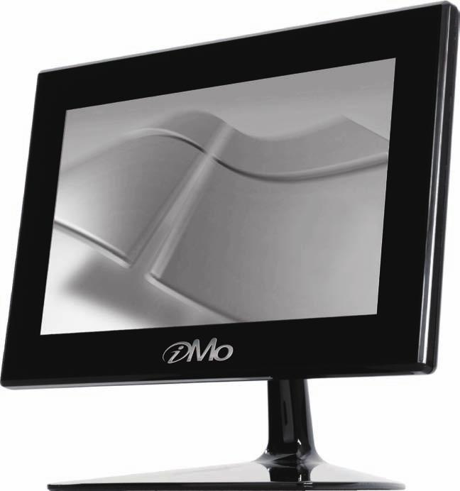
5 Product Features USB No power cable required. Simple access to PC with USB cable. High speed 2.0 USB interface. Touchscreen Full Touchscreen Interface Pivot function Pivot function. High quality LCD panel Bright 7 TFT active matrix LCD screen (800x480) Brightness adjustable. Removable Stand Application of removable type stand for portable use. 6


6 AT-7 User Guide Product and Components This product is packaged with the following components. Frame Stand Portable Stand Installation CD USB Cable Manual 7
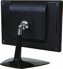
7 Identify each part The back of the product It describes the appearance and the name of each part. Some differences in appearance and function might occur depending on the model 1 Brightness Control Button 5 Power Switch 2 USB Slot 4 Stand Joint 3 Stand Joint No. Name Description 1 Brightness Control Button [ + ] Set Brightness up. [ - ] Set Brightness down. 2 USB Slot Connect monitor to PC by using USB Cable. 3 Swivel type stand joint. Stand Joint 4 Stick type stand joint. 5 Power Switch Switch the power on or off 8

8 AT-7 User Guide Making connecting to your PC Connect the USB cable to the PC s USB port and to the device. Note Make sure that the PC s power is turned off when connecting the cable. A C B When connecting the USB cable to the PC s USB port, connect [A] part to the PC and [C] part to the device. Connect [B] part to the PC s other USB port when there when there is insufficient power supply from only one USB connection. Note This product is powered by USB cable only. 9


9 Driver Program Installation (For Windows OS) USB Monitor Turn on the PC and connect the PC with the device by using the USB cable included with USB sub-monitor (AT-7). When the device is connected to the PC using USB cables, adequate power will be supplied to the device. 1. Insert the included installation CD. When the CD is inserted, the driver Installer image will be displayed USB Monitor Driver Touch Driver Exit Note - When Auto Install processing is not activated, click on the AutoRun file on the driver CD for Installation. - Power or USB cable disconnection, during the process of installation may cause serious error on the PC or OS system. 2. Select the USB Monitor Driver button. 3. After selecting the USB Monitor Driver, the installation process will be displayed. Click [Agree] to proceed with the installation process. Terms of use will be displayed. Click [Agree]. Note Please operate the PC with the owner s ID and password for proper installations. Please read the terms of use thoroughly before clicking [Agree] button. 4. USB installation program will be automatically started. When [AT-7] icon is formed at the right corner of the task bar, USB driver installation is completed. Remove the CD from the PC. Use [Remove Hardware Safely] function to remove the USB cable safely. Reboot the PC. 10

10 AT-7 User Guide Touch Driver Program Installation (For Windows OS) Turn on the PC and connect the PC with the device by using the USB cable included with USB sub-monitor (AT-7). When the device is connected to the PC using USB cables, adequate power will be supplied to the device. 1. Insert the included installation CD. When the CD is inserted, the driver Installer image will be displayed USB Monitor Driver Touch Driver Exit Note - When Auto Install processing is not activated, click on the AutoRun file on the driver CD for Installation. - Power or USB cable disconnection, during the process of installation may cause serious error on the PC or OS system. 2. Select the Touch Driver button. 3. After selecting the Touch Driver button, the driver package installation wizard will guide user to install Touchside driver software package. Click [Next] button to proceed installation. 4. The Installation wizard pops up below dialog to hint user to check this check box if the PS/2 interface of touchscreen is going to be used. By default, this check box is unchecked. Then, press [Next] button to proceed installation. 11


11 Touch Driver Program Installation (For Windows OS) 5. The installation pops up below dialog for calibration option. Touchside provides 3 options for calibration. Every System boot up : The 4-point calibration utility will launch automatically whenever the system boot up. Next System boot up : The 4-point calibration utility will launch automatically at next system boot up. None : The 4-point calibration utility will NOT launch automatically. Choose the proper option, and click [Next] button to continue. 6. After selecting the Touch Driver button, the driver package installation wizard will guide user to install Touchside driver software package. Click [Next] button to proceed installation. 7. Touchside driver package supports multi monitors. Please check the check box to support multi-monitor feature. The multi-monitor setting property page will show only when this check box is checked during installation. Press [Next] to continue. 8. The installation wizard pops up below dialog to let user assign the target folder in local machine. Press [Next] to continue. 12
 9.")


12 AT-7 User Guide Touch Driver Program Installation (For Windows OS) 9. The installation wizard pops up below dialog to show the program folder. Press [Next]to continue. 10. The driver software files are being copied. 11. After files copied, the wizard begins searching Touchside devices on COM ports. 12. Once the serial Touchside device is found, the below dialog pops up for user to confirm to install kernel mode driver for this device. 13

13 Touch Driver Program Installation (For Windows OS) 13. After driver installed, below dialog pops up so that users do calibration now. 14. Finally, the Touchside utility is launched. If PS/2 interface of driver is installed, it needs to reboot system to make sure the driver is installed. When [Touch side] icon is formed at the right corner of the task bar, Touch driver installation is completed. Remove the CD from the PC. Use [Remove Hardware Safely] function to remove the USB cable safely. Reboot the PC. 14

14 AT-7 User Guide Driver Program Installation (For Windows OS) Configuration Touchside Utility General Property Page The general property page in TouchSide utility shows all of TouchSide touchscreen controllers installed as below, including RS232, USB and PS2 interfaces. User can select the controller list in the window to do configuration for it. When user use a mouse or other input device to select the controller device in the controller list window, The controller name will be shown in the title bar of the main window( the property sheet ). Also, all of the other property pages will be updated for this selected controller. In some application, user may in place edit and change the controller name for easy identification. In addition, there are 2 function push buttons in this prope 1. Add The function button is used for serial RS232 controllers only. Press this button to search the TouchSide serial controllers connected with the system COM ports. Whenever it finds a new TouchSide serial controller, a new serial controller icon object will be shown in the controller list window automatically. USB TouchSide device supports plug and play, the icon object for USB controller will be shown in the controller list window automatically when the USB controller is connected with the system USB port. And, the icon object for the USB controller will disappear automatically as soon as the device was removed from the system USB port. TouchSide PS2 driver support PS2 mice and TouchSide touchscreen controller. It can works with both PS2 mice and TouchSide touchscreen PS2 controller. After the TouchSide PS2 driver was installed, this utility assumes the PS2 touchscreen controller exists and is always shown in the controller list window. 15

15 Driver Program Installation (For Windows OS) Configuration Touchside Utility 2. Remove This function button is used for serial RS232 controllers only. This button will be greyed and disabled automatically when the selected controller in the controller list window is not RS232 type. Press to remove and uninstall the selected serial RS232 controller from the system. Then, this serial RS232 icon object in controller list window disappears automatically. USB TouchSide device supports plug and play, the icon object for USB controller will be shown in the controller list window automatically when the USB controller is connected with the system USB port. And, the icon object for the USB controller will disappear automatically as soon as the device was removed from the system USB port. TouchSide utility does not allow user to remove/uninstall the PS2 device driver dynamically. To uninstall the TouchSide PS2 driver, user needs to go to Windows Device Manager to do un-installation. In addition, after PS2 un-installation, it needs to system reboot to complete un-installation. Monitor Property Page TouchSide driver utility supports multiple monitor and display system. To work with multiple monitor system, user needs to do proper configuration to map the touchscreen working area to the correct system display area. User can do such configuration with this property page shown as below, Display The system monitor display geometry was shown in the Monitors window in this page to show the locations of all of the monitors of the system. Note xtouchmon.exe is another utility for TouchSide touchscreen system. This tray icon utility can monitor the system monitor display configuration change and correct the touchscreen monitor mapping relationship automatically as soon as the system monitor display configuration changed. We strongly suggest the user to make sure xtouchmon.exe was launched for multiple monitor system. User can follow below instructions to do the configuration 1. Enable multiple monitor Check this check box to enable multiple monitor support and uncheck it to disable multiple monitor support. When this function is disabled, the touchscreen will be mapped to the primary monitor automatically. When this function is enabled, user can double click on the monitor area in the monitor geometry window to assign the monitor area where the touchscreen will be mapped. In other word, the touchscreen will work with the selected monitor. Then, the selected monitor area rectangle line will be changed to be white and the other monitor rectangles line will be grey. 16
16 AT-7 User Guide Driver Program Installation (For Windows OS) Configuration Touchside Utility 2. Map to main monitor when the system has only one monitor When the multiple monitor function was enabled, and the system has only one monitor, Driver allows user to generate the mouse event for the primary monitor or not when the touchscreens which were not mapped to primary monitor. Check the check box to enable this function, then, the driver will generate the mouse event for the primary monitor even through the touchscreen was configured as other monitor mapping and multiple monitor function enabled. 3. Operation Mode TouchSide driver support split display mode for those applications which do not map the touchscreen to the full screen of the monitor. 3-1) Full screen The touchscreen will be mapped to the full screen of the specified monitor. 3-2) Right screen The touchscreen will be mapped to the right half screen of the specified monitor. 3-3) Left screen The touchscreen will be mapped to the left half screen of the specified monitor. 3-4) Upper screen The touchscreen will be mapped to the upper half screen of the specified monitor. 3-5) Lower screen The touchscreen will be mapped to the lower half screen of the specified monitor. 3-6) Other operation mode 3-6-1) Quarter 1 The touchscreen will be mapped to the first quarter area of the specified monitor display ) Quarter 2 The touchscreen will be mapped to the 2nd quarter area of the specified monitor display ) Quarter 3 The touchscreen will be mapped to the 3rd quarter area of the specified monitor display ) Quarter 4 The touchscreen will be mapped to the 4th quarter area of the specified monitor display ) Customized If the touchscreen needs to be mapped the area other than the above area, user can define the mapping area for application. With this mode, the driver does not correct the mapping area when the display resolution changed. It needs to do configuration setting again whenever the display resolution changed. 17

17 AT-7 User Guide Driver Program Installation (For Windows OS) Configuration Touchside Utility Tool Property Page Calibration, draw test tools and the linearity curve of the touchscreen were list in this property page shown as below for user to do touchscreen calibration and touch position test. User can do calibration or draw test by pressing the function push buttons. 1. Linearization Curve Linearization curve of the touchscreen is list in this page for reference and trouble shooting purpose points calibration It needs calibration before the touchscreen can work accurately. Whenever the user feel the accuracy lost, user can do calibration again to get a more accuracy touch function. Pressing this button, a new window will be popped-up at the location when the touchscreen was mapped to area for this touch system to guide the user do 4 points calibration. User should follows the guide to touch and hold the blinking X symbol in the calibration window until it does not blink to make sure that the utility can gather enough data for computation. In addition, a time line bar is shown in the bottom of the window to indicate time elapsed. If the touchscreen was not touched before the time line bar going to right end, the calibration task will be terminated automatically points calibration It needs calibration before the touchscreen can work accurately. Whenever the user feel the accuracy lost, user can do calibration again to get a more accuracy touch function. Pressing this button, a new window will be popped -up at the location when the touchscreen was mapped to area for this touch system to guide the user do 4 points calibration. User should follows the guide to touch and hold the blinking X symbol in the calibration window until it does not blink to make sure that the utility can gather enough data for computation. In addition, a time line bar is shown in the bottom of the window to indicate time elapsed. If the touchscreen was not touched before the time line bar going to right end, the calibration task will be terminated automatically.
 function is used to compensate the touchscreen linearity.")


18 AT-7 User Guide Driver Program Installation (For Windows OS) Configuration Touchside Utility 4. Linearization Linearization ( 25 or 9 points calibration ) function is used to compensate the touchscreen linearity. After linearization completed, the linearity of the touchscreen will be shown in the Linearity curve window. Pressing this button, a new window will be popped -up at the location when the touchscreen was mapped to area for this touch system to guide the user do 25 points calibration. User should follows the guide to touch and hold the blinking X symbol in the calibration window until it does not blink to make sure that the utility can gather enough data for computation. In addition, a time line bar is shown in the bottom of the window to indicate time elapsed. If the touchscreen was not touched before the time line bar going to right end, the calibration task will be terminated automatically. 5. Draw Test This function is used for accuracy and performance check. Press this button and a new pop up window will be popped up in the location where the touchscreen was mapped to the touch system as below, User can press the Clear button to clear the window. Press Quit button to terminate this draw test. xtouchmon utility TouchSide software package contains an utility to monitor some events related to touchscreen application. After TouchSide software package installed, a tray icon utility was shown in the system task bar as below. Whenever the mouse cursor moves on the tray icon, a tool tip shows as This is a fast tool for user to change some driver setting without launching the TouchSide configuration utility. When user right click on this tray icon, a pop up context menu shows as below, This pop up menu shows the all of the functions this utility supports. 19


19 Driver Program Installation (For Windows OS) Configuration Touchside Utility 1. Apply To Touchscreen When user selects this function, the sub-menu shows all of the TouchSide devices installed in the system. User can choose the next function configuration settings will be applied to which devices. xtouchmon allows the configuration settings applied to all of the TouchSide devices or some specified devices. 2. Mouse Mode This Mouse mode has sub-menu as below to show all of the mouse emulation modes the driver supports. This mouse emulation mode changed will be applied to the specified devices. 3. Beep User can change the Beep Mode with this function menu. And, the change will be applied to the specified devices immediately. 4. Auto Right Click User can enable/disable auto right click function with this function menu. The change will be applied immediately to those specified devices. 5. Button This button is designed to show/hide the right button window Points calibration Select this function to pop up the 4 points calibration window for user to do calibration for those specified devices. 7. TouchSide Utility TouchSide configuration utility will be launched if user selects this function. 8. Support Rotation Monitor display rotation support. Enable it, this utility will correct the touchscreen orientation to match with monitor display orientation whenever it detects monitor rotation. This correction will be done automatically if the system video adapter driver supports Microsoft Win32 APIs for monitor rotation. If the video adapter driver does not support Microsoft Win32 API for monitor rotation, the utility will pop up a one point calibration window to correct the orientation mapping. 9. Exit Exit function to terminate the xtouchmon daemon process. After this daemon process terminated, all of functions the utility supports will be disabled. In addition to above functions, xtouchmon also monitors monitor display setting change. It will correct the coordination mapping automatically except the touchscreen work with customized area mode whenever it detect monitor resolution change, numbers of system monitors change. 20

20 AT-7 User Guide Driver Program Installation (For Mac OS) USB Monitor Double click on imo Installer image to run imo Installer. [Display Link Software Installer] Select DisplayLink Software Installer to install USB driver program. Follow the instructions. The computer has to be re-booted in order to complete the installation process. [User Guide] Please choose user guide to view the user guide. [Display Link Software Uninstaller] Select DisplayLink Software Installer to uninstall USB driver program. The computer has to be re-booted in order to complete the un-installation process. Note - Please refer to the user guide to learn more about its use under Mac OS. - This device supports Intel-based MAC OS X version only. Touch 1. Select TouchKit Software Installer to install Touch driver program. 2. Touch driver program start installing. 21
 3.")
![Press [Continue] button to](/docs-images/93/113108685/images/21-1.jpg "continue. 4.")


21 Touch Driver Program Installation (For Mac OS) 3. Press [Continue] button to continue. 4.Select the destination folder that installs TouchKit. 5. After installing the software, the system will restart automatically. If users want toreboot, press [Continue Installation]. 6. Installation is in progress. 7. Press [Restart] to reboot Mac OS x. 22

![After installing TouchKit, go to the sub-menu [Application] and double click [TouchKit Utility] to start the TouchKit diagnosis window.](/docs-images/93/113108685/images/22-1.jpg "Please check touch panel devices (included its controller) are equipped well, then those components will be displayed the Panel List dialogue box. There is one or more devices found.")

22 AT-7 User Guide Driver Program Installation (For Mac OS) Configuration Touchside Utility The touch-sensitive area of the panel and touch sensitivity both can be modulated through the configuration utility. Besides, the controller identification and deviceactivated shall be done first. After installing TouchKit, go to the sub-menu [Application] and double click [TouchKit Utility] to start the TouchKit diagnosis window. Please check touch panel devices (included its controller) are equipped well, then those components will be displayed the Panel List dialogue box. There is one or more devices found. The controller is displayed on the Panel List box. User can get the information of interface, type, version and model for each controller. Select one device after import more than one device at the panel list window. The one selected will activate the panel. There are two property pages in TouchKit utility, and they are General and About. Each property page contains different functions for users to do the adjustments. Therefore, users can easily manage all the TouchKit controllers through TouchKit Utility. General General property page contains the functions of [4 pts Cal], [Draw Test] and [Advanced]. 4 pts Cal Correct 4 point locations on screen with the panel. Press [4 pts Cal], screendisplays as follows. Touch the blinking symbol on panel until beep or stop blinking. 23
![Driver Program Installation (For Mac OS) Configuration Touchside Utility Draw Test Test the drawing position related to the display screen on panel. Click on the [Draw Test] button.](/docs-images/93/113108685/images/23-0.jpg "There will be a squared blue display showing. Try to write or draw on it to verify the touch position. Press [CLEAR] for cleaning touch screen, and press [QUIT] to exit Draw Test.")
![Advanced Advanced property page contains two pages of 25 Pts Cal and Setting. Press [Clear] to clear the previous calibration records. Press [Yes] to clear previous records.](/docs-images/93/113108685/images/23-2.jpg "The record will become default record. Then, press [25 pts Cal] to execute 25 points calibration. Correct 25 point locations on screen with the panel.")
23 Driver Program Installation (For Mac OS) Configuration Touchside Utility Draw Test Test the drawing position related to the display screen on panel. Click on the [Draw Test] button. There will be a squared blue display showing. Try to write or draw on it to verify the touch position. Press [CLEAR] for cleaning touch screen, and press [QUIT] to exit Draw Test. Advanced Advanced property page contains two pages of 25 Pts Cal and Setting. Press [Clear] to clear the previous calibration records. Press [Yes] to clear previous records. The record will become default record. Then, press [25 pts Cal] to execute 25 points calibration. Correct 25 point locations on screen with the panel. Touch the blinking symbol on panel until beep or stop blinking. After the calibration, the new record will overwrite the old one. Setting Mouse mode: There are three kinds of mouse mode users could choose, Normal Mode It provides all the mouse functions, including the dragging function. Click on Touch Click action is executed as soon as users touch the panel. Click on Release Click action will not be executed until finger leaves the panel. 24

24 AT-7 User Guide Driver Program Installation (For Mac OS) Configuration Touchside Utility Support Constant Touch: Enable Constant Touch to force driver to stop reporting touch point when the movement is within the range which users can adjust. Therefore, the user can see a stabilized cursor instead of a chattering cursor when userstouch the same point with unwanted noise. Support Auto Right Button: Enable Auto Right Button to force driver to report a right click mouse event to OS when users do a continuing touch till time out. It no longer needs to touch the right button in the Touchtray to activate a right click. This feature makes users to do right click more easily with touchscreen. About Information about TouchKit. QUIT Exit TouchKit touch panel configuration utility. 25
![Using Touch USB sub monitors Click [AT-7] icon to view the menu screen. Refresh menu View the driver s refreshed information or perform environment settings.](/docs-images/93/113108685/images/25-0.jpg "[Check] : Check the driver s refreshed information. [Environment setting] : Perform driver s environment setting. Screen resolution menu Screen resolution is set as 800x480.")
, it displays a better screen but the PC speed may be compromised.")
![[Medium (16 bit)] : Approximately 65,000 colors are being depicted. [Very high(32 bit)] : Approximately 4,294,000,000 colors are being depicted.](/docs-images/93/113108685/images/25-2.jpg "Screen rotation menu It is used when the device is being rotated. [Normal] : It is a setting used for normal use of the device.")
![[Rotate to the left]: It is a setting used when the device is rotated 90 to the left. The screen on the device will rotate 90 to the right.](/docs-images/93/113108685/images/25-3.jpg "[Rotate to the right]: It is a setting used when the device is rotated 90 to the right. The screen on the device will rotate 90 to the left.")
25 Using Touch USB sub monitors Click [AT-7] icon to view the menu screen. Refresh menu View the driver s refreshed information or perform environment settings. [Check] : Check the driver s refreshed information. [Environment setting] : Perform driver s environment setting. Screen resolution menu Screen resolution is set as 800x480. Higher resolutions will result in clear and detailed screen. This product is set in 800x480 settings. Color quality menu May be set based on user resolutions When they are set as very high (32 bits), it displays a better screen but the PC speed may be compromised. [Medium (16 bit)] : Approximately 65,000 colors are being depicted. [Very high(32 bit)] : Approximately 4,294,000,000 colors are being depicted. Screen rotation menu It is used when the device is being rotated. [Normal] : It is a setting used for normal use of the device. [Rotate to the left]: It is a setting used when the device is rotated 90 to the left. The screen on the device will rotate 90 to the right. [Rotate to the right]: It is a setting used when the device is rotated 90 to the right. The screen on the device will rotate 90 to the left. [Rotate to the left]: It is a setting used when the device is rotated 180 to the left. Expansion direction menu Send the screen sent out to the USB monitor in different directions. [Right] : Drag the screen to the right of the device and from the PC. [Left] : Drag the screen to the left of the device and from the PC. [Upward] : Drag the screen upward to the device and from the PC. [Downward] : Drag the screen downward to the device and from the PC. 26

26 AT-7 User Guide Using Touch USB sub-monitors Expansion menu PC screen may be dragged into the device s screen. Simply drag the desired screen into the device s monitor. Note Mirror function will allow the user to view the same screen as the PC screen. Mirror menu Mirror function will allow the user to view the same screen as the PC screen. Note When mirror menu is selected, PC s screen will be set as the same setting as the USB sub monitor screen. Therefore, when the PC s screen is larger than 800x480 resolutions, it will be automatically reduced to match the USB monitor setting and display the same screen. Turn off menu Turn off the USB monitor function. When the USB monitor is turned off, [Expansion Direction], [Expansion], [Mirror] and [Advanced] functions are the only functions that are activated. [Screen resolution], [Color quality] and [Rotation] functions are deactivated. In order to release the monitor from [Off] status, select [Expansion Direction], [Expansion] or [Mirror] functions. Advanced menu Select the setting from the USB sub monitor s display environment settings. Note Detailed USB monitor settings are possible in the display setting window. Even though it may differ from different PCs, user PC monitor is set as number 1 monitor and USB monitor (XT-7) is set as either number 2 or 3 monitor in normal uses. 27
27 Troubleshooting Problem imo does not power up after USB cable is connected I cannot see the screen clearly The screen is frozen The system would not reboot after the connection Dos screen that appears during PC booting does not appear on the screen Solution Did you run your installation program after connecting the device? Please use the Installation Software in the CD. Please refer to the USB driver program installation for detailed information. Make sure that the USB cables are properly connected. Make sure that the Installation Software is properly installed. 1. Right click on My Computer and open the properties window. 2. Click device manager in the Hardware tab. 3. Click PC located at the top part of the tree in the device management window. 4. Click search hardware modifications in Action (A) menu. 5. Reboot the PC. This device is recognized as a normal USB device. Since frequent rebooting of the PC may damage the USB device, please refer to Microsoft s USB device troubleshooting section for further supports. Check hardware acceleration from the properties menu. Set the hardware acceleration value to maximum. 1. Open display registration information by right clicking the screen. 2. After selecting setting tab, select nanovision minimonitor. 3. Click Advanced 4. When the screen does not pop up, click troubleshooting tab. Set hardware acceleration as maximum. In one-board type computers using i815 chipset mother boards, disable the Legacy USB support in the BIOS setting menu and reboot the PC again. Since entering BIOS may require different steps for different PCs, please refer to your manuals carefully. Follow instructions from Microsoft help. Since this device is a USB device, Dos screen will not appear during the booting process. 28
28 AT-7 User Guide Troubleshooting Problem You cannot perform 3D games on this screen I would like to know which OS are being support How many devices may be connected to a single PC? How can I completely remove the installation program? Solution This is a USB monitor device that receives USB 2.0 High Speed(480Mbps) signals. Therefore, it is unable to support various programs that require 3D acceleration functions. Device uses may be limited based on PC s properties (CPU or memory) - Limited programs (1) Real Player (Do not support expansion mode) (2) Most of 3D games (3) Programs running based on Direct X - Supported movie programs (1) Windows Media Player (Supports versions higher than 10) (2) Power DVD (5) Win DVD(Version 5 onwards) 1. Windows Vista 32bit is supported. - Windows Vista 64bit is not currently supported. 2. Windows XP Service Pack 2 is supported. - Service Packs under version 1 is not supported. - It is optimized for Windows XP Service Pack 2 and USB 2.0 settings. 3. Windows 2000 Service Pack 4 is supported. - Service Packs under version 3 is not supported. - It is optimized for Windows 2000 Service Pack 4 and USB 2.0 settings. Monitors do not function properly with USB 1.0 ports. Theoretically, Up to 127 devices may be connected to the PC. However, the following numbers are our recommendations. 1. When connecting 1-2 units Minimum PC requirement: 1.2GHz CPU / 512 MB Memory 2. When connecting 3 units Minimum PC requirement: 1.8GHz CPU / 1GB Memory 3. When connecting 6 units Minimum PC requirement : 1.6GHz Dual core CPU / 1GB Memory Adequate amount of frame speed may not be supported depending on the use of PC s resources. When you click add/remove program from the control panel, a list of installed programs will appear. Click on [DisplayLink Graphics] and click remove button. 29
29 Troubleshooting Problem Even when the connection is disconnected and the power is turned off, device information is still remaining in the display registration information I would like to clean the device Where can I download the drivers and software that I purchased? On connection of a USB device to the PC, the message "USB Device Not Recognized" appears in the Windows system tray The device is not working under my Mac OS. The device stops working after updating the OS to version Solution When the USB monitor is turned off or disconnected, it will be deactivated from the system. In order to erase this information, you must remove [DisplayLink Graphics] program from the control panel. However, when the program is removed, it must be reinstalled before using the device again. Since this device is a LCD monitor, it is attached with a thin anti-reflection film.since it is very susceptible to scratching and chemicals, please refer to the following instructions carefully during the cleaning process. 1 Use soft cloth (such as the cloth used to clean eyeglasses) Normal cloth may leave scrathches on the screen. 2 When cleaning agents are used, please use exclusive cleaning agent for cleaning LCD screens. - If other alkali or soap cleaning agents are used it may damage and discolor the LCD screen. - Do not spray cleaning agents directly onto the screen. LCD screen may be discolored and damaged when cleaning agents are directly sprayed onto the screen. Please spray the agent on the cloth before cleaning the screen. 3 Do not put pressure onto the screen to clean the LCD screen thoroughly. Clean the screen 2-3 times with a soft touch. You may download it from our homepage ( Refer to the user manual for the homepage address and download the drivers. - Check other USB devices are recognised by the PC. Ensure that you are using a good quality USB cable and test again by using a different USB port on the PC, for example a port at the back of a desktop PC. - If using a docking station, remove all other devices that may be connected to the dock and try again. - If the problem persists, then you should contact the original manufacturer of the product. IMO monitor is compatiable with Intel-based Mac OS X version only. Please check the main chipset and OS version. - A beta driver is now available that addresses this issue. Please visit to download the beat release (1.1.3b1). - If you still continue to encounter problems after installing this driver, please ask a Question in our Support Portal. 30
30 AT-7 User Guide Specifications Display USB Power supply Function Interface Size / Resolution Brightness TFT7 / 800X cd/ m2 Contrast 500:1 USB 2.0 High speed USB Power supply Touch Sub Monitor by USB connection only Brightness Control Extend to 4 directions (Up/Down/Right/Left) Screen rotation (Clockwise) Mirror function USB mini to 5-pin B-type Input key 2 tact switch : Brightness Up, Down PC Requirement Dimensions(mm) Intel Pentium/Celeron 1.2GHz above RAM 1GB above USB 1 port above HDD 500MB capacity Windows 2000 (SP4), Windows XP (SP2, SP3), Windows VISTA (32bit, 64bit) Mac OS X equipped with Intel CPU 194x133x23.5mm (WxHxD) 31
31 THIS DEVICE COMPLIES WITH PART 15 OF THE FCC RULES. OPERATION IS SUBJECT TO THE CONDITIONS: (1) THIS DEVICE MAY NOT CAUSE HARMFUL INTERFERENCE, AND (2) THIS DEVICE MUST ACCEPT ANY INTERFERENCE RECEIVED, INCLUDING INTERFERENCE THAT MAY CAUSE UNDESIRED OPERATION. Caution Changes or modifications not expressly approved by the party responsible for compliance could void the user s authority to operate the equipment. Note FCC Information This equipment has been tested and found to comply with the limits for a Class B digital device, pursuant to Part 15 of the FCC Rules. These limits are designed to provide reasonable protection against harmful interference in a residential installation. This equipment generates, uses and can radiate radio frequency energy and, if not installed and used in accordance with the instructions, amy cause harmful interference to radio communications. However, there is no guarantee that interference will not occur in a particular installation. If this equipment does cause harmful interference to radio or television reception, which can be determined by turning the equipment off and on, the user is encouraged to correct the interference by one or more of the following measures: -- Reorient or relocate the reveiving antenna. -- Increase the separation between the equipment and reveiver. -- Connect the equipment into an outlet on a circuit different from that to which the receiver is connected. -- Consult the dealer or an experienced radio/tv technician for help. 32
32
epos Touchkit Manual (for Windows XP)
") epos Touchkit Manual (for Windows XP) 1. Touchkit Devices in Windows Device Manager After driver installation completed, all of Touchkit touchscreen controller devices will be list in the Mice and other
epos Touchkit Manual (for Windows XP) 1. Touchkit Devices in Windows Device Manager After driver installation completed, all of Touchkit touchscreen controller devices will be list in the Mice and other
7 USB Monitor EB-7DM Manual
 7 USB Monitor EB-7DM Manual CONTENTS 1. Safety Instructions... 2. Product Features... 3. connections and Installation... 4. Installation Monitor Driver... 5. EB-7DM Display Setting... 6. System Requirements...
LV4000U LCD Pole Display
 LV4000U LCD Pole Display Contents Warning... 3 FCC Warning Statement... 3 Introduction... 4 Features...4 Unpacking the display...4 Installation... 5 Assembly...5 Control Buttons...5 Driver Installation
TouchKit TouchScreen Controller User Manual for imac Version: 1.0.8
 TouchKit TouchScreen Controller User Manual for imac Version: 1.0.8 1 CONTENT: CHAPTER 1. TOUCH PANEL CONTROLLER 2 1.1 Controller 2 1.2 Specifications and Features 3 CHAPTER 2. INSTALLING TOUCHKIT 5 2.1
TouchScreen Controller User Manual
 TouchScreen Controller User Manual for Mac Version: 1.0.8 Customer : Model : 32-4W232/4WUSB/5W232/5WUSB-BB Date : Version: Acceptance Sheet Onetouch Technologies Co., Ltd. (Supplier) (Purchaser) Date Approval
TouchKit TouchScreen Controller User Manual for Mac Version: 1.0.8
 TouchKit TouchScreen Controller User Manual for Mac Version: 1.0.8 TouchKit Manual for Mac v1.0.8 0 CONTENT: CHAPTER 1. TOUCH PANEL CONTROLLER...2 1.1 CONTROLLER...2 1.2 SPECIFICATIONS AND FEATURES...3
TouchKit TouchScreen Controller User Manual for Windows NT4 Version: 3.4.0
 TouchKit TouchScreen Controller User Manual for Windows NT4 Version: 3.4.0 1 CONTENT CHAPTER 1. TOUCH PANEL CONTROLLER 2 1.1 Controller 2 1.2 Specifications and Features 3 CHAPTER 2. INSTALLING TOUCHKIT
TouchKit TouchScreen Controller User Manual for imac Version: 1.0.8
 TouchKit TouchScreen Controller User Manual for imac Version: 1.0.8 TouchKit Manual for imac v1.0.8 0 CONTENT: CHAPTER 1. TOUCH PANEL CONTROLLER... 2 1.1 CONTROLLER... 2 1.2 SPECIFICATIONS AND FEATURES...
TouchKit TouchScreen Controller User Guide for Windows NT4 Version: 3.2.1
 TouchKit TouchScreen Controller User Guide for Windows NT4 Version: 3.2.1 TouchKit Guide for WinNT4 v3.2.1 0 CONTENT CHAPTER 1. TOUCH PANEL CONTROLLER... 2 1.1 CONTROLLER... 2 1.2 SPECIFICATIONS AND FEATURES...
Please read this guide before using the printer
 PD-450/450W/480/480W User Guide Please read this guide before using the printer Safety Precautions Safety Precautions Denotes the possibility of serious injury or death Use only recommended power sources.
CANTEEN 6000 Portable Battery Pack NAP-30. Instruction Manual Please read carefully before use and keep for future reference.
 CANTEEN 6000 Portable Battery Pack NAP-30 Instruction Manual Please read carefully before use and keep for future reference. Thank You We know you have many choices when it comes to technology; thank you
DRIVE DOCK. User Guide
 DRIVE DOCK User Guide CONTENTS Introduction 1.1 Minimum System Requirements...1 1.1.1 Apple Mac Requirements 1.1.2 PC Requirements 1.1.3 Supported Drives 1.2 Package Contents...1 1.3 About This Manual...1
7-Port Fast Charging Station NAP Instruction Manual Please read carefully before use and keep for future reference.
 7-Port Fast Charging Station NAP-7000 Instruction Manual Please read carefully before use and keep for future reference. Thank You We know you have many choices when it comes to technology; thank you for
REV. 1.3
 www.mimomonitors.com REV. 1.3 Warning : It displays the cases where a mistaken handling may cause an infliction of death or serious injury to a person. Caution : It displays the cases where a mistaken
DRIVE DOCK. User Guide
 DRIVE DOCK User Guide CONTENTS INTRODUCTION 1.1 Minimum System Requirements...1 1.1.1 Apple Mac Requirements 1.1.2 PC Requirements 1.1.3 Supported Drives 1.2 Package Contents...1 1.3 About This Manual...1
User Guide. Digital Picture Key Chain NS-DKEYBK10/ NS-DKEYRD10
 User Guide Digital Picture Key Chain NS-DKEYBK10/ NS-DKEYRD10 Digital Picture Key Chain Contents Introduction............................... 3 Safety information......................... 3 Features..................................
Smartphone Photo Printer
 Smartphone Photo Printer Safety Precautions Safety Precautions Denotes the possibility of serious injury or death Please keep you away at least 20cm distance from printer when printing. Use only recommended
BLUETOOTH CLOCK RADIO
 BLUETOOTH CLOCK RADIO SCR1989BT OPERATING INSTRUCTIONS Please read and follow this instruction manual carefully before using the unit and retain it for future reference SYLVANIA is a registered trademark
User s guide for Xtenda TM
 User s guide for Xtenda TM (X300 Series) Copyright by Ncomputing Co. Ltd. 2004. - Illegal copying of this software, hardware and this documentation is prohibited by law. All other brand- and product names
DRIVE DOCK. User Guide
 DRIVE DOCK User Guide CONTENTS INTRODUCTION 1.1 Minimum System Requirements...1 1.1.1 Apple Mac Requirements 1.1.2 PC Requirements 1.1.3 Supported Drives 1.2 Package Contents...1 1.3 About This Manual...1
QIT600F1 USER'S GUIDE
 QIT600F1 USER'S GUIDE 1 IMPORTANT SAFEGUARDS Warnings: 1. Read all of these instructions. Save these instructions for later use, please. 2. Unplug this monitor from the wall outlet before cleaning. Do
DSS Console and DSS Console for Attendant for Digital Super Hybrid Systems. Reference Guide ANSWER RELEASE
 ANSWER RELEASE PSQX1526ZA 98.8.5 7:32 PM Page 1 DSS Console and DSS Console for Attendant for Digital Super Hybrid Systems Reference Guide Model KX-T7440/KX-T7441 8 16 24 32 40 48 7 15 23 31 39 47 6 14
ThinkPad Bluetooth Laser Mouse User Manual
 ThinkPad Bluetooth Laser Mouse User Manual About this manual Thank you for your purchase of this Bluetooth mouse set. This topics covered in this manual are listed as following. (This mouse will be sold
cenomax F350 User Manual 使用手冊 3.5 Digital Photo Frame Revision 1.0a
 cenomax F350 3.5 Digital Photo Frame User Manual 使用手冊 Revision 1.0a FCC compliance statement Note: This equipment has been tested and found to comply with the limits for a Class B digital device, pursuant
SOFTRAID FOR THUNDERBAY. Quick Start Guide
 SOFTRAID FOR THUNDERBAY Quick Start Guide CONTENTS Introduction... 1 1.1 Minimum System Requirements 1.2 Features 1.3 About This Manual Easy Setup... 2 2.1 About Easy Setup 2.2 Using Easy Setup Using SoftRAID...
Model WT1 Wireless Tablet Interface
 Model WT1 Wireless Tablet Interface User Manual Model WT1 Wireless Tablet Interface Thank you for purchasing the Califone Model WT1 Wireless Tablet Interface. We encourage you to visit our website www.
Quick Installation Guide
 Quick Installation Guide For Network Attached Storage Ver.1.1.0.0320 Table of Contents Notices... 3 Safety Precautions... 4 1. Package Contents... 5 2. Hardware Installation Guide... 6 2.1. Hard Disk Installation...
TouchScreen Controller User Manual
 TouchScreen Controller User Manual for Windows 9X / ME Version: 3.4.0 Customer : Model : 32-4W232/4WUSB/5W232/5WUSB-BB Date : Version: Acceptance Sheet Onetouch Technologies Co., Ltd. (Supplier) (Purchaser)
TouchKit TouchScreen Controller User Guide for Windows 2000 / XP Version: 3.2.4
 TouchKit TouchScreen Controller User Guide for Windows 2000 / XP Version: 3.2.4 TouchKit Guide for Win2000/XP v3.2.4 0 CONTENT CHAPTER 1. TOUCH PANEL CONTROLLER...2 1.1 CONTROLLER...2 1.2 SPECIFICATIONS
Quick Reference Guide
 DSS Console Quick Reference Guide Model No. KX-T7740 Important Information When using the KX-T7740, keep the following in mind. If there is any trouble, disconnect the DSS Console from the telephone line
Hardware Installation 1. Install two AA batteries in the mouse. Pairing Process in Vista and Windows XP SP2
 Hardware Installation 1. Install two AA batteries in the mouse. Pairing Process in Vista and Windows XP SP2 1. Open the Windows control panel, then select Bluetooth devices. 2. Click Add.. 3. Select My
RocketStor Dual-Bay Thunderbolt TM 10Gb/s Storage Dock
 RocketStor 5212 Dual-Bay Thunderbolt TM 10Gb/s Storage Dock Quick Installation Guide V1.02 Apr. 3, 2014 1 Table of Contents Table of Contents...2 HighPoint RocketStor 5212...3 Kit Contents...3 RocketStor
OWC Mercury On-The-Go Pro USER GUIDE
 OWC Mercury On-The-Go Pro USER GUIDE TABLE OF CONTENTS 1. INTRODUCTION... 1 1.1 MINIMUM SYSTEM REQUIREMENTS 1.1.1 Apple Mac Requirements 1.1.2 PC Requirements 1.2 PACKAGE CONTENTS 1.3 ABOUT THIS MANUAL
Assembly Manual & User Guide
 Assembly Manual & User Guide TABLE OF CONTENTS 1. INTRODUCTION... 1 1.1 MINIMUM SYSTEM REQUIREMENTS 1.1.1 Apple Mac Requirements 1.1.2 PC Requirements 1.2 PACKAGE CONTENTS 1.3 ABOUT THIS MANUAL 1.4 FRONT
Safety and Maintenance You can use your Tablet PC under a wide range of environmental conditions. However, to ensure long use and continued high
 EVG7 DL46 Getting Started Congratulations on your purchase of a Tablet PC. The Tablet PC is a fully functional PC with built-in LAN, and wireless connectivity. With your Tablet PC you will be able to organize
USB to VGA/DVI Adapter. Model #: U R. USB to VGA Adapter. Model #: U VGA-R. USB to HDMI Adapter. Model #: U HDMI-R
 Warranty Registration: register online today for a chance to win a FREE Tripp Lite product www.tripplite.com/warranty Owner s Manual USB to VGA/DVI Adapter Model #: U244-001-R USB to VGA Adapter Model
ENG. LCD Monitor Series Prestigio P TFT Active Matrix LCD Panel User s Manual. Prestigio P1910 1
 LCD Monitor Series Prestigio P1910 19.0 TFT Active Matrix LCD Panel User s Manual Prestigio P1910 1 I. Federal Communications Commission (FCC) Statement: This Equipment has been tested and found to comply
USB 3.0 to DisplayPort Adapter. Model #: U DP. USB 3.0 to DVI Adapter. Model #: U R. USB 3.0 to HDMI Adapter. Model #: U HDMI-R
 Warranty Registration: register online today for a chance to win a FREE Tripp Lite product www.tripplite.com/warranty Owner s Manual USB 3.0 to DisplayPort Adapter Model #: U344-001-DP USB 3.0 to DVI Adapter
ATRx Biometric Package Contents: Minimum System Requirements: INSTALLATION GUIDE BIOMETRIC HANDPUNCH TECHNOLOGY
 ATRx Biometric 1000 BIOMETRIC HANDPUNCH TECHNOLOGY Thank you for purchasing ATRx Biometric 1000. This installation guide will help you learn how to connect the handpunch reader, enable biometrics in the
Indoor Mini Dome. Hardware Manual D91, D92, E91, E92. Ver. 2013/06/14
 Indoor Mini Dome Hardware Manual D91, D92, E91, E92 Ver. 2013/06/14 Table of Contents Precautions 3 Safety Instructions... 5 Introduction 6 List of Models... 6 Package Contents... 7 Physical description...
TouchKit Touch Panel User manual for WindowsNT4 Version: 3.1.4
 TouchKit Touch Panel User manual for WindowsNT4 Version: 3.1.4 TouchKit Touch Panel v3.1.4 0 CONTENT CHAPTER 1. TOUCH PANEL CONTROLLER...2 1.1 CONTROLLER...2 1.2 SPECIFICATIONS AND FEATURES...3 CHAPTER
Owner s Manual. USB 2.0 to VGA Adapter
 Owner s Manual USB 2.0 to VGA Adapter Model: U244-001-VGA PROTECT YOUR INVESTMENT! Register your product for quicker service and ultimate peace of mind. You could also win an ISOBAR6ULTRA surge protector
SPK User Manual. 900MHz Wireless Stereo Headphones INTRODUCTION FEATURES IMPORTANT SAFETY INFORMATION
 INTRODUCTION Thank you for purchasing our 900Mhz compact cordless stereo headphone system that takes advantage of the very latest advances in wireless transmission technology so you SPK-9100 900MHz Wireless
THUNDERBAY 4 MINI. Assembly Manual & User Guide
 THUNDERBAY 4 MINI Assembly Manual & User Guide CONTENTS INTRODUCTION 1.1 Minimum System Requirements...1 1.1.1 Apple Mac Requirements 1.1.2 PC Requirements 1.1.3 Supported Drives 1.2 Package Contents...1
Owner s Instruction Manual
 Owner s Instruction Manual Advanced Healthcare Telephone Model 5150 Contents IMPORTANT SAFETY INSTRUCTIONS...3 BOX CONTENTS...4 FEATURES...4 ON/OFF SWITCH...4 DIAL BUTTONS...4 RECEIVER VOLUME CONTROL...4
PACKAGE CONTENTS LOCATION OF CONTROLS. The package comes with the following items: PC Camera User s Manual Microphone
 PACKAGE CONTENTS The package comes with the following items: PC Camera User s Manual Microphone LOCATION OF CONTROLS 1 2 3 1. Focus Ring Manual Focus 2. USB Cable 3. Swivel Mounting Clamp 1 INSTALLATION
TouchKit Touch Panel User manual for WindowsNT4 Version: 3.1.4
 TouchKit Touch Panel User manual for WindowsNT4 Version: 3.1.4 TouchKit Touch Panel v3.1.4 0 CONTENT CHAPTER 1. TOUCH PANEL CONTROLLER... 2 1.1 CONTROLLER... 2 1.2 SPECIFICATIONS AND FEATURES... 3 CHAPTER
Mercury Helios ASSEMBLY MANUAL & USER GUIDE
 Mercury Helios ASSEMBLY MANUAL & USER GUIDE TABLE OF CONTENTS INTRODUCTION...1 1.1 MINIMUM SYSTEM REQUIREMENTS 1.1.1 Apple Mac Requirements 1.1.2 PC Requirements 1.1.3 Supported PCIe Cards NOTE: Boot Camp
The following symbols are used to show dangerous operation or handling. Make sure you understand them before reading the guide.
 Safety Instructions Before use Thank you very much for purchasing this product. This product is an interface box called "Connection & Control Box" for EPSON short throw projectors. For your safety, read
6 Lens Digital Microscope Instruction Manual
 6 Lens Digital Microscope Instruction Manual Model #: SCT18 www.hamiltonbuhl.com CONTENTS BEFORE USE 4 USING THE XPLOVIEW SOFTWARE 16 Important Information 4 Care and Maintenance 4 Warning 4 Product Description
C ookie User Manual BC
 Cookie User Manual BC Cookie Please follow the instruction in this guide to enjoy the best sound. Cookie User Manual Hold "O" button to power on and off Press "O" button to play/pause music (for compatible
TouchKit Touch Panel User manual for Windows9X/ME Version: 3.1.4
 TouchKit Touch Panel User manual for Windows9X/ME Version: 3.1.4 TouchKit Touch Panel v3.1.4 0 CONTENT CHAPTER 1. TOUCH PANEL CONTROLLER... 2 1.1 CONTROLLER... 2 1.2 SPECIFICATIONS AND FEATURES... 3 CHAPTER
HD-PGDU3. User Manual
 HD-PGDU3 User Manual www.buffalotech.com 35020486-01 2014-05 Contents LEDs and Connections...3 Specifications...4 Recommended Usage...5 Warning...5 Dismounting the Unit...6 Troubleshooting...7 I can see
For your safety and protection of the E-bot, please read and abide by the following important safety precautions.
 2 P age Safety Precautions For your safety and protection of the E-bot, please read and abide by the following important safety precautions. 1) Do not plug the AC adapter into a faulty electrical outlet.
SOFTRAID. Quick Start Guide
 SOFTRAID Quick Start Guide TABLE OF CONTENTS INTRODUCTION... 1 1.1 Minimum System Requirements 1.2 Features 1.3 About This Manual SYSTEM SETUP... 2 2.1 Getting Started 2.2 Initializing, Verifying, and
Owner s Manual USB 3.1 Gen 1 (5 Gbps) Display Adapters
 Display Adapters") Owner s Manual USB 3.1 Gen 1 (5 Gbps) Display Adapters Models #: U444-06N-HD, U444-06N-VGA PROTECT YOUR INVESTMENT! Register your product for quicker service and ultimate peace of mind. You could also
Owner s Manual USB 3.1 Gen 1 (5 Gbps) Display Adapters Models #: U444-06N-HD, U444-06N-VGA PROTECT YOUR INVESTMENT! Register your product for quicker service and ultimate peace of mind. You could also
Quick Installation Guide
 Quick Installation Guide For Network Attached Storage Ver.1.1.0.0517 Table of Contents Notices... 3 Safety Precautions... 4 1. Package Contents... 5 2. Hardware Installation Guide... 6 2.1. Hard Disk Installation...
Mercury Elite Pro mini ASSEMBLY MANUAL & USER GUIDE
 Mercury Elite Pro mini ASSEMBLY MANUAL & USER GUIDE TABLE OF CONTENTS 1. INTRODUCTION... 1 1.1 MINIMUM SYSTEM REQUIREMENTS 1.1.1 Mac Requirements 1.1.2 PC Requirements 1.2 PACKAGE CONTENTS 1.3 ABOUT THIS
SLIMLINE DASH CAM Audio & Video Recorder
 SLIMLINE DASH CAM Audio & Video Recorder 1 EK142CAM INSTRUCTION MANUAL PLEASE READ ALL INSTRUCTIONS CAREFULLY AND RETAIN FOR FUTURE USE Getting Started Remove the Car Digital Video Recorder from the box.
MultiPlex 15 Touch Screen. User s Manual
 MultiPlex 5 Touch Screen User s Manual Preface Precautions. READ INSTRUCTIONS: All the safety and operating instructions should be read before the LCD monitor is operated.. RETAIN INSTRUCTIONS: The safety
SUBWOOFER SYSTEM YST-MSW10
 ACTIVE SERVO PROCESSING SUBWOOFER SYSTEM YST-MSW10 Active Servo SUBWOOFER SYSTEM YST-MSW10 Active Servo HIGH CUT HIGH LOW OWNER S MANUAL MANUAL DE INSTRUCCIONES CAUTION RISK OF ELECTRIC SHOCK DO NPT OPEN
YST-SW20 SUBWOOFER SYSTEM OWNER S MANUAL. Active Servo Technology
 CAUTION SUBWOOFER SYSTEM Active Servo RISK OF ELECTRIC SHOCK DO NOT OPEN CAUTION: TO REDUCE THE RISK OF ELECTRIC SHOCK DO NOT REMOVE COVER (OR BACK). NO USER-SERVICEABLE PARTS SIDE. REFER SERVICG TO QUALIFIED
 POWER + - + + - INPUT 2010 INNOVAGE LLC All Rights Reserved. Project Name: ProjectorS35_IM Designer/Studio: INNOVAGE Revision: SET UP AND INSTALLATION RCA cables generally cannot be connected to a TV (unless
Wireless Smart Pad And Mini Keyboard User s Manual
 Wireless Smart Pad And Mini Keyboard User s Manual Version 1.0 2010/08 ID NO: About This Manual This manual is designed to assist you in installing and using the Wireless Touchpad Keyboard. Information
User Manual Infinity:One
 User Manual Infinity:One For the latest updates and information, please visit: support.one-education.org Notice The information in this user s manual is protected by copyright laws, all parts of this manual,
RocketCache 32xx Series HBA
 RocketCache 32xx Series HBA Add SSD Performance to Your HDD Storage User s Guide v1.2 1 Contents HighPoint RocketCache 32xx Series Host Adapter...3 Kit Content...3 Hardware Installation...4 RocketCache
Always there to help you. Register your product and get support at SPA1330. Question? Contact Philips.
 Always there to help you Register your product and get support at www.philips.com/welcome Question? Contact Philips SPA1330 User manual Contents 1 Important 2 Safety 2 Notice 3 English 2 Your multimedia
Fixed Network Camera Hardware User Manual
 Fixed Network Camera Hardware User Manual FCS-3054, FCS-3065, FCS-3092 Ver. 2014/01/09 Table of Contents Precautions 3 Safety Instructions... 5 Introduction 6 List of Models... 6 Package Contents... 7
ViewXnet. Ethernet to DVI/VGA adapter USER S MANUAL
 ViewXnet Ethernet to DVI/VGA adapter USER S MANUAL FEDERAL COMMUNICATIONS COMMISSION This device complies with Part 15 of the FCC Rules Operation is subject to the following two conditions: this device
OWC Mercury Pro Optical ASSEMBLY MANUAL & USER GUIDE
 OWC Mercury Pro Optical ASSEMBLY MANUAL & USER GUIDE Copyright 2015 Other World Computing All Rights Reserved. Other World Computing s Limited Warranty is not transferable and subject to limitations. TABLE
TouchKit TouchScreen Controller User Guide for imac Version: 1.0.5
 TouchKit TouchScreen Controller User Guide for imac Version: 1.0.5 TouchKit Guide for imac v1.0.5 0 CONTENT: CHAPTER 1. TOUCH PANEL CONTROLLER...2 1.1 CONTROLLER...2 1.2 SPECIFICATIONS AND FEATURES...3
Voyager S3. User guide
 Voyager S3 User guide TABLE OF CONTENTS INTRODUCTION...1 1.1 Minimum System Requirements 1.1.1 Apple Mac Requirements 1.1.2 PC Requirements 1.1.3 Supported Drives 1.2 Package Contents 1.3 About This Guide
N331 Wireless Mini Optical Mouse User s Guide
 N331 Wireless Mini Optical Mouse User s Guide Mouse 1. Left mouse button 2. Right mouse button 3. Scroll wheel 4. Charge port 5. Battery cover 6. Receiver storage compartment 7. Battery cover release button
THUNDERBAY 4. Assembly Manual & User Guide
 THUNDERBAY 4 Assembly Manual & User Guide CONTENTS Introduction...1 1.1 Minimum System Requirements 1.1.1 Apple Mac Requirements 1.1.2 PC Requirements 1.1.3 Supported Drives 1.2 Package Contents 1.3 About
The following symbols are used to show dangerous operation or handling. Make sure you understand them before reading the guide.
 Safety Instructions Before use Thank you very much for purchasing this product. This product is an interface box called "Connection & Control Box" for EPSON short throw projectors. For your safety, read
OPERATING INSTRUCTIONS POWERSMART 10 10,000 MAH PORTABLE POWER PLEASE READ BEFORE OPERATING THIS EQUIPMENT
 POWERSMART 10 10,000 MAH PORTABLE POWER OPERATING INSTRUCTIONS PLEASE READ BEFORE OPERATING THIS EQUIPMENT HALO POWERSMART 10 Thank you for choosing HALO. Innovative and easy to use, the HALO POWERSMART
Kanguru QSSD External SSD USB3.0 User Manual
 Copyright 2012, All Rights Reserved. Kanguru QSSD External SSD USB3.0 User Manual Notices and Information NOTICES AND INFORMATION Please be aware of the following points before using your Kanguru QSSD
TABLE OF CONTENTS INTRODUCTION...1 DEVICE SETUP...4 SUPPORT RESOURCES...9
 TABLE OF CONTENTS INTRODUCTION...1 1.1 Minimum System Requirements 1.2 Package Contents 1.3 About This Manual 1.4 Rear View 1.4.1 Rear Features 1.5 Usage Notes DEVICE SETUP...4 2.1 Quick Start 2.2 Assembly
1. Product Description. 2. Product Overview
 1. Product Description Avantree Pluto Air is a multi-function Bluetooth speaker with high quality music performance and mini compact design. This mini speaker can allow you to stream music from Bluetooth-enabled
THUNDERBAY 4. Assembly Manual & User Guide
 THUNDERBAY 4 Assembly Manual & User Guide TABLE OF CONTENTS INTRODUCTION...1 1.1 MINIMUM SYSTEM REQUIREMENTS 1.1.1 Apple Mac Requirements 1.1.2 PC Requirements 1.1.3 Supported Drives: up to four 3.5 SATA
Quick Installation Guide
 Quick Installation Guide Applicable Models: AS6004U Ver.3.0.0 (2017-4-13) Table of Contents Notices... 3 Safety Precautions... 4 1. Package Contents... 5 2. Optional Accessories... 6 3. Hardware Installation
Slim Super Multi DVD Writer
 ENGLISH OWNER S MANUAL Slim Super Multi DVD Writer To enjoy fully all the features and functions of your product, please read this owner s manual carefully and completely. GTC0N Safety Instructions CAUTION:
Labtec Wireless Optical Desktop. Getting Started Guide
 Labtec Wireless Optical Desktop Getting Started Guide Important Ergonomic Information Long periods of repetitive motions using an improperly set-up workspace, incorrect body position, and poor work habits
USER MANUAL CW14Q1P. CW14Q1P MANUAL-EN 70g 书纸,135x102mm
 CW14Q1P MANUAL-EN 70g 书纸,135x102mm USER MANUAL CW14Q1P Thank you for your choosing the new device This guide serves to enable users to get to know and familiar with our product as soon as possible. Here
P OCKET POWER 9000 T. Powerful Universal Portable Charger PLEASE READ BEFORE OPERATING THIS EQUIPMENT
 P OCKET POWER 9000 T M Powerful Universal Portable Charger PLEASE READ BEFORE OPERATING THIS EQUIPMENT HALO POCKET POWER 9000 Thank you for choosing HALO. Innovative, fashionable and easy to use, the HALO
888385_01 Install.book Page 1 Wednesday, November 11, :45 PM. SMDR6 Installation Guide
 888385_01 Install.book Page 1 Wednesday, November 11, 1998 2:45 PM SMDR6 Installation Guide 888385_01 Install.book Page 2 Wednesday, November 11, 1998 2:45 PM 888385_01 Install.book Page i Wednesday, November
BAM Labs Biometric Monitoring System. Instruction Manual
 BAM Labs Biometric Monitoring System Instruction Manual 2 Contents Customer Instructions...4 Intended Use...4 IMPORTANT SAFETY INSTRUCTIONS...5 WARNINGS...6 FCC Warning...7 LED Feedback...9 Connecting
CP MultiTouch Controller
 CP450-010 MultiTouch Controller Welcome! We greatly appreciate your purchase of the CP450. We are sure you will find it reliable and simple to use. Superior performance for the right price, backed by solid
Contents FCC COMPLIANCE STATEMENT PRECAUTIONS GETTING READY
 USER MANUAL Contents FCC COMPLIANCE STATEMENT PRECAUTIONS GETTING READY Package Contents Knowing the device BASIC OPERATIONS OF THE PROJECTOR Turning On/Off the Projector Adjusting Focus Resizing the Projection
Logitech Alert 700i/750i System Requirements & Support Guide
 Logitech Alert 700i/750i System Requirements & Support Guide Contents System Requirements............................ 3 Product Information............................ 4 Contact Us..................................
TouchScreen for Display & Panel-PC
 TouchScreen for Display & PanelPC User Manual for Windows 2000 / XP Version: 4.0.2 TouchKit Manual for Win2000/XP v4.0.2 Page 1 CONTENT CHAPTER 1. TOUCH PANEL CONTROLLER... 3 1.1 CONTROLLER... 3 1.2 SPECIFICATIONS
Ultra Slim Super Multi DVD Writer
 ENGLISH OWNER S MANUAL Ultra Slim Super Multi DVD Writer To enjoy fully all the features and functions of your product, please read this owner s manual carefully and completely. GS40N Safety Instructions
Bluetooth Micro Dongle User s Guide. Rating: 5V DC 80mA Made in China
 Bluetooth Micro Dongle User s Guide Rating: 5V DC 80mA Made in China Introduction Package Contents USB Bluetooth adapter x 1 Installation CD x 1 (includes Bluetooth software and User s Guide) User s Guide
LV4000U LCD Pole Display
 LV4000U LCD Pole Display Contents Warning... 3 FCC Warning Statement... 3 Introduction... 4 Features...4 Unpacking the display...4 Installation... 5 Assembly...5 Control Buttons...5 Driver Installation
BRS 2001 Portable Audio System
 Samson Electronics Inc. 3400 E. Slauson Ave. Maywood, CA 90270 Ph: 323.585.6393 Fax: 323.585.6202 Web: http://www.blackmoremobile.com Introduction: BRS 2001 Portable Audio System FCC ID: 2AHR7 BRS 2000
Fixed Network Camera Hardware User Manual
 Fixed Network Camera Hardware User Manual FCS-0032 Ver. 2013/12/04 Table of Contents Precautions 3 Safety Instructions... 5 Introduction 6 List of Models... 6 Package Contents... 6 Physical Description...
EXPRESS. Assembly Manual & User Guide
 EXPRESS Assembly Manual & User Guide CONTENTS Introduction... 1 1.1 Minimum System Requirements 1.2 Drive Compatibility 1.3 Package Contents 1.4 Enclosure Features 1.5 About This Manual Device Setup...
WIRELESS THIN-PROFILE KEYBOARD AND MOUSE USER S MANUAL.
 WIRELESS THIN-PROFILE KEYBOARD AND MOUSE USER S MANUAL www.jascoproducts.com TABLE OF CONTENTS 1. INTRODUCTION...3 2. PACKAGE CONTENTS...3 3. SYSTEM REQUIREMENT...3 4. INSTALLATION INSTRUCTIONS...3 5.
Table of Contents. Federal Communications Commission (FCC) Statement...2
 Statement...2") Contents Table of Contents Federal Communications Commission (FCC) Statement...2 Important Safety Instructions...3 Chapter 1 Introduction Features...6 Package Contents...7 Front View and Controls...8 Installing
Contents Table of Contents Federal Communications Commission (FCC) Statement...2 Important Safety Instructions...3 Chapter 1 Introduction Features...6 Package Contents...7 Front View and Controls...8 Installing
INSTRUCTION MANUAL MODEL # I ENGLISH
 INSTRUCTION MANUAL MODEL # 44114 1 I ENGLISH 1. INTRODUCTION Thank you for purchasing the Celestron MicroSpin Digital Microscope. Please read this instruction manual carefully before using this product