OPERATING MANUAL. ELECTRICAL APPLIANCE SAFETY TESTERS PAT-810, PAT-815 and PAT-820. SONEL S. A. 11 Wokulskiego Str Świdnica, Poland
|
|
|
- Theodore Flynn
- 5 years ago
- Views:
Transcription
1
2
3 OPERATING MANUAL ELECTRICAL APPLIANCE SAFETY TESTERS PAT-810, PAT-815 and PAT-820 SONEL S. A. 11 Wokulskiego Str Świdnica, Poland Version
4 PAT-810/815/820 testers are modern, high-quality testers, easy and safe in operation. Please acquaint yourself with the present manual in order to avoid measuring errors and prevent possible problems related to operation of the tester. 2 OPERATING MANUAL PAT-810/815/820 version 1.06
5 TABLE OF CONTENTS 1 SAFETY GENERAL DESCRIPTION AND FEATURES OF THE INSTRUMENT SWITCHING ON AND MAIN MENU POWER SUPPLY START TEST AFTER SWITCHING THE TESTER ON GENERAL SETTINGS MENU Symbols on screen Setting date and time Interface settings Measurement settings Printing PAT specifications Firmware upgrade Information about tester and producer Service Network setting List of Users Memory structure (Clients, Objects, Subobjects and Appliances) Adding Clients Adding Objects Adding Appliances Deleting clients, objects and appliances Communication with PC MEASUREMENTS PRELIMINARY TEST MEASUREMENT OF PE RESISTANCE MEASUREMENT OF INSULATION RESISTANCE Measurement of RISO on Class I devices Measurement without using the test socket Measurement of RISO on Class II (III) devices RISO measurement of IEC power cord DURABILITY OF INSULATION (FLASH TEST) ONLY PAT Measurement on Class I devices Measurement on Class II devices MEASUREMENT OF SUBSTITUTE LEAKAGE CURRENT MEASUREMENT OF PE LEAKAGE CURRENT MEASUREMENT OF DIFFERENTIAL LEAKAGE CURRENT MEASUREMENT OF TOUCH LEAKAGE CURRENT OPERATING MANUAL PAT-810/815/820 version
6 4.9 MEASUREMENT OF P AND S POWER, PF POWER FACTOR, CURRENT CONSUMPTION AND VOLTAGE CURRENT MEASUREMENT WITH CLAMP (ONLY PAT-815 AND PAT-820) IEC CABLE TEST MEASUREMENT OF FIXED RCD PARAMETERS AUTO MODE TESTS Configuring AUTO mode tests AUTO mode tests Doing measurements (of items like IEC leads, extension leads) with RCD in AUTO mode MEMORY OF MEASUREMENT RESULTS DATA STORING THE MEASUREMENT RESULTS IN THE MEMORY BROWSING MEMORY DATA SEARCH OPTION IN THE MEMORY MOVING APPLIANCE INTO ANOTHER OBJECT COPYING CLIENT S DATA FROM MEMORY INTO USB FLASH DRIVE (BACK AND FORTH) DELETING MEMORY DATA LABEL PRINTING CLEANING AND MAINTENENCE STORAGE DISMANTLING AND DISPOSAL ANNEXES SPECIFICATIONS STANDARD ACCESSORIES OPTIONAL ACCESSORIES MANUFACTURER OPERATING MANUAL PAT-810/815/820 version 1.06
7 1 Safety PAT-810/815/820 testers are designed for performing check tests on electrical equipment, providing measurement results which determine the safety status of tested devices. Therefore, in order to provide conditions for correct operation and the correctness of the obtained results, the following recommendations must be applied: Before you commence operating the tester, acquaint yourself thoroughly with the present manual and observe the safety regulations and specifications determined by the manufacturer. Any application that differs from those specified in the present manual may result in a damage to the device and constitute a source of danger for the user. PAT-810/815/820 testers must be operated only by appropriately qualified personnel. Operating the tester by unauthorised personnel may result in damage to the device and constitute a source of danger for the user. Using this manual does not exclude the need to comply with occupational health and safety regulations and with other relevant fire regulations required during the performance of a particular type of work. Before starting the work with the device in special environments, e.g. potentially firerisk/explosive environment, it is necessary to consult it with the person responsible for health and safety. It is forbidden to operate the following: A damaged tester which is completely or partially out of order, A tester with damaged test leads insulation, A tester stored for an excessive period of time in disadvantageous conditions (e.g. excessive humidity). If the tester has been transferred from a cool to a warm environment with a highlevel of relative humidity, do not start measurements until the tester is warmed up to the ambient temperature (approximately 30 minutes). The tester may be powered only from grounded mains sockets. Before starting any measurement, make sure the test leads are connected to the proper test sockets. Do not touch the tested device during measurements. Test sockets and the socket for testing IEC cables are protected against improper connection to the voltage up to 300V AC for 60 seconds. Repairs may be carried out only by an authorised service point. NOTE! Only standard and additional accessories for a given device should be used, as listed in the "Equipment" section. Use of different accessories can lead to errors in the test connection and can introduce additional measurement uncertainties. NOTE: Due to continuous development of the tester s software, the actual appearance of the display, in case of some of the functions, may slightly differ from the display presented in this operating manual. OPERATING MANUAL PAT-810/815/820 version
8 Note: An attempt to install drivers in 64-bit Windows 8 may result in displaying "Installation failed" message. Cause: Windows 8 by default blocks drivers without a digital signature. Solution: Disable the driver signature enforcement in Windows. 2 General description and features of the instrument PAT-810/815/820 digital testers are intended to measure the basic parameters of portable electrical devices (power tools, household appliances, etc.) important for their safety: protective conductor resistance, insulation resistance, continuity of connections, leakage current and RCDs. The testers may be used to test equipment in accordance with the following standards: EN Hand-held motor-operated electric tools. Safety. Part 1: General requirements. EN Safety of transportable motor operated electric tools. General requirements. EN Household and similar electrical appliances. Safety. Part 1: General requirements. EN Information technology equipment Safety- Part 1: General requirements. EN Electrical safety in low voltage distribution systems up to V a.c. and V d.c. - Equipment for testing, measuring or monitoring of protective measures - Part 6: Effectiveness of residual current devices (RCD) in TT, TN and IT systems. VDE Testing and Measuring Equipment for Checking the Electric Safety of Electric Devices - Part 1: General Requirements. VDE Testing and Measuring Equipment for Checking the Electric Safety of Electric Devices - Part 2: Testing Equipment for Tests after Repair, Change or in Case of Repeat Tests. VDE Inspection after Repair, Modification of Electrical Appliances. Repeat Testing of Electrical Equipment. General Requirements for Electrical Safety. AS/NZS 3760:2010 In-service safety inspection and testing of electrical equipment. Basic functions of the instrument: Measurement of network voltage and frequency Checking the resistance of L-N circuit Measurement of protective conductor resistance (Protection class - I): technical measurement method measurement with sinusoidal current of network frequency and following currents: 200mA, 10A (only PAT-815/820) and 25 A (only PAT-815/820) adjustable measurement time adjustable upper limit in the range of: 10mΩ 1.99Ω with 0.01Ω resolution Measurement of insulation resistance: three test voltages: 100 V (only PAT-815/820), 250 V (only PAT-815/820) and 500 V measurement of insulation resistance up to 599 M automatic discharge of the capacitance of tested object after the insulation resistance measurement is completed adjustable measurement time adjustable lower limit within the range of MΩ with 0,1MΩ resolution Flash test (only PAT-820) 6 OPERATING MANUAL PAT-810/815/820 version 1.06
9 Measurement of substitute leakage current:: adjustable measurement time adjustable upper limit in the range of: ma with 0.01mA/0.1mA resolution Measurement of PE leakage current: adjustable measurement time adjustable upper limit in the range of: ma with 0.01mA/0.1mA resolution measurement of the current with clamp Measurement of differential leakage current: adjustable measurement time adjustable upper limit in the range of: ma with 0.01mA/0.1mA resolution measurement of the current with clamp Measurement of touch leakage current: adjustable measurement time adjustable upper limit in the range of: ma with 0.01mA/0,1mA resolution Measurement of Power P and S Power measurement PF Power Factor measurement Current consumption measurement Measurement with the PAT's internal measurement circuits or with clamp Measurement of RCD s parameters I Δn = 10 ma, 15 ma, 30 ma Measurement of I A, t A for 0,5 I Δn, 1 I Δn, 2 I Δn,5 I Δn IEC lead test Other: automatic selection of measuring range tree structure of measurement results memory with provision of printing or transfering the results to PC via USB facilities configurable with a bar-code scanner and printer industrial computer equipped with large, readable, touch graphic display PAT's power supply sustained for 15 minutes after disconecting mains power supply with the use of built-in battery ergonomic operation OPERATING MANUAL PAT-810/815/820 version
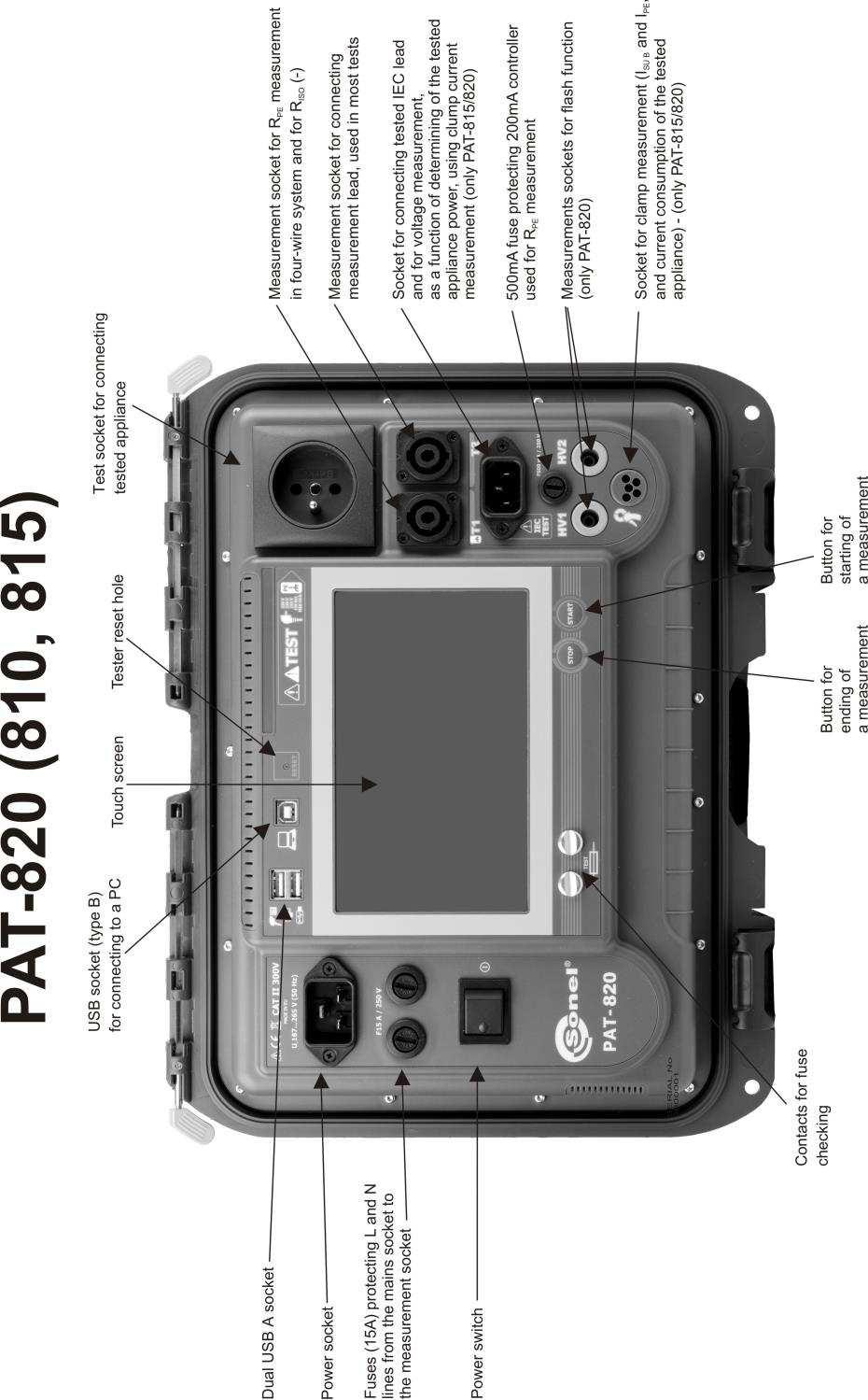
10 3.1 Power supply 3 Switching on and Main Menu The device is 195 V 265 V, 50 Hz mains powered. Two 15A fuses protect L and N lines from the supply socket to the test socket, they are tripped when current consumption from the test socket is too high (>16A). 500mA fuse protects 200mA current controller for R PE measurement. 3.2 Start test after switching the tester on After switching on, the tester performs a self-test to check its correct operational condition and when this test is successfully completed, the tester automatically performs the following measurements: measurement of the voltage in the power supply socket, i.e. the voltage between L and N of power supply to the tester, measurement of mains frequency, checking the continuity PE in the power supply socket, measuring the voltage between N and PE in the power supply socket, indicates swapped L and N terminals (icon on the screen). Upon completing above mentioned measurements main Menu screen is displayed as below, along with the results of the measurements: 8 OPERATING MANUAL PAT-810/815/820 version 1.06
11 Note: - For mains voltages below 195 V and above 256 V all test functions are automatically locked out. Additional information displayed on the screen On the right upper corner of the screen mains network monitor is presented. It shows polarity of the power supply, voltage between N and PE, voltage between L and N, and mains frequency. Other information: Dangerous voltage on PE Note: Note: Incorrect voltage of the supply. Switch on tester again with an audible signal Voltage U N-PE > 25 V or lack of PE continuity, measurements are blocked. Mains voltage > 265 V, measurements are blocked. Correct polarity of power supply (L i N), measurements possible. Uncorrect polarity of power supply, swapped L and N in the power supply socket of the tester. PAT automatically swaps L and N in the tester s test socket, and measurements are possible. - Error message indicating incorrect voltage frequency may be caused by supplying power from an unstable voltage source (e.g. generator). 3.3 General settings MENU In the MENU the following actions are available: Auto tests, Manual tests, Browse memory, Configuration of tester: Date and time: setting date and time, Interface: swithing on/off audible signals and choice of language, Tests: setting nominal mains voltage and additional options, Printing: printing settings, Specifications, About tester and producer, Firmware upgrade (update), Service, Network setting: Wi-Fi confoguration, List of users, PC connection. OPERATING MANUAL PAT-810/815/820 version
12 Notes: - Settings are saved and remembered after switching off the tester. - Auto tests, Manual tests and Browsing memory are described in other chapters of this manual Symbols on screen - go back to the main menu - add new element (client, site, appliance), another measurement in multibox function - save data (select device when saving to memory) - opening Site or Appliance data - deleting Site or Appliance - moving Appliance into other Site - move one level up or - previous screen (window) or - next screen - close the window without saving changes - searching (e.g. client, site, appliance) - help - editing data of the selected element (e.g. client, site, appliance) or - checkbox, mark inside the square means that the selected option is on or given content assigned to this field has been confirmed and is correct. 10 OPERATING MANUAL PAT-810/815/820 version 1.06
13 - commencing Auto test procedure - connection with selected network WiFi (see sec ) Others: - connect measurement probe to the object - appliance under test must be switched on - NOTE: mains voltage in the measurement socket of the tester during the mesurement. Appliance under test will switch on and go - press START to start the test - the tester is ready to commence the test - test procedure is in progres Setting date and time Press Configuration of tester. Press Date and Time. OPERATING MANUAL PAT-810/815/820 version


14 Press the field you intend to change. In the date edit window type in proper value and press to proceed to editing next parameter or press Enter to save changes and close the window. After entering new values press Set to confirm the date and time settings. 12 OPERATING MANUAL PAT-810/815/820 version 1.06

15 3.3.3 Interface settings Press Configuration of tester. Press Interface. Pressing sqare Auto Increment Appliance/Device ID ON turn on or off automatic incrementing of the registration number assigned to the next added device. Pressing sqare Sound messages turn on or off sound signals. Pressing Language go to the choice of language. OPERATING MANUAL PAT-810/815/820 version


16 3.3.4 Measurement settings Press Configuration of tester. Press Test. Select chosen options by ticking empty squares. Press Mains nominal voltage [V]: 220/230/240, to change nominal network voltage powering the tester. Select the proper voltage, and close the window. Notes: - Warnings: Show warning about dangerous voltage switch on/off warnings about the possibility of the voltage being dangerous to user that may appear during tests. Show warning about switched off appliance switch on/off notification that the tested device is not connected or it's not turned on. Warn about the possibility of losing unsaved results switch on/off warning indicating possible loss of unsaved data, e.g. when the user is closing windows filled with data without saving changes. Note: It is advised for less experienced users to keep all the above warnings on. 14 OPERATING MANUAL PAT-810/815/820 version 1.06

17 - Auto-tests: Perform auto-tests automatically switch on/off automatic mode of performing autotests, which is performing the complete set of autotests after single press of START button. - Polarity IEC L-N: Allow reverse polarity IEC L-N allows interchanging of L and N lines in the tested IEC conductor, the test result is displayed as positive. - Power cord for the device: Save lead after ticking this box, the power cord is saved in the memory and printed on a printout as a separate device, otherwise it is considered as an integral part of the device Printing Press Configuration of tester. Press Print. Select chosen options by ticking empty squares. Notes: Enable print document enable/disable printer. Auto print: printing automatically after the test is finished. Logo placing SONEL logo on the print-out. Prefered format: Detailed contains a list of questions of the visual examination together with the assessment and the results of individual measurements with the assessment. Standard includes overall result of the test, logos and additional data (name of the device, measuring person). Shorted similar to standard format but without the logo and additional information. Templates for automatic printout: OPERATING MANUAL PAT-810/815/820 version

18 Appliance label label with a test result of an appliance. Appliance + IEC label label with a test result of an appliance and IEC power cord. RCD label label with an RCD test result. Print line with retest [months]: Printing stripe on the left, right, or both sides of the label, depending on the number of the months, after which retest of the appliance must be done. The number of months is selected by clicking on proper field, similarily to setting date and time PAT specifications Press Configuration of tester. Press Specifications. A window with general measurement parameters of the tester will be displayed. Detailed parameters are listed in the PAT Operating Manual. 16 OPERATING MANUAL PAT-810/815/820 version 1.06


19 3.3.7 Firmware upgrade In order to upgrade the PAT's firmware, new firmware has to be downloaded from website. The new firmware file has to be uploaded into USB flash drive. It is advised to copy all the data from the tester's memory before starting upgrading procedure, to avoid accidental memory erase. Press Configuration of tester. Press Update. Read the warning message. To perform an update insert the USB drive with the update files and click Update or ensure Internet connection of the meter via WiFi, and click Download and update. Press YES only if the upgrade asks for it, as all data stored in the memory will be erased, along with all user settings. In most cases user should press NO. OPERATING MANUAL PAT-810/815/820 version


20 This screen shows up only when USB flash drive is not inserted or it's not detected/proper. Insert USB flash disk with upgrade files on it and press Update to upgrade the firmware or press Cancel to cancel upgrading procedure. Note: - Firmware upgrade is preformed automatically and can be completed in several stages. During the upgrade procedure it is not allowed both to switch off the tester's power supply and to remove USB flash drive. Once the upgrade is completed it will be confirmed by the below message. Remove USB flash disk and press OK to complete the upgrade procedure. Note: - Upon completing this operation the tester will reset. It is not allowed to swith off the tester's power supply at this stage. The upgrading/configuring changes process is continued and will last until main MENU screen comes up. Only at this stage it is allowed to switch off the power supply or to start using the tester. 18 OPERATING MANUAL PAT-810/815/820 version 1.06

21 3.3.8 Information about tester and producer Press Configuration of tester. Press About tester and producer. The tester data and the producer information window Service This function ic available solely for service and protected with the password Network setting Note: LAN may be available in devices copies on request. Press Configuration of tester. Press Network setting. OPERATING MANUAL PAT-810/815/820 version

.")
22 To get information about local active networks WiFi press Available networks. A network requiring the password was found. To add to the memory founded network press (select) the name of the network and press (Add). Press field Password:, type password required for this network and press (Save). 20 OPERATING MANUAL PAT-810/815/820 version 1.06

23 The network is saved and connected with the tester, connection s parameters are available. The button On/Off on the right turns on or off the WiFi module in the tester. Pressing Prefered network enables displaying networks saved already in the tester. The network selected with is the network currently connected with the tester. Pressing (selecting) the network s name allows: with the button (Connect) connection with the selected network (provided it is active on this territory), OPERATING MANUAL PAT-810/815/820 version

24 with the button (Delete) removal of selected network, with the button (Edit) changing of the password List of Users Press Users. Users are introduced to signing test s performers. The tester can be used by many people. Each person can log in with his own login and password. Passwords are introduced to prevent the signing of the test someone else's name. Only Administrator can add and delete users. Others can only change their own data. Test results stored in tester's memory are tagged with user names, indicating users who were logged in while performing tests. Additionally, the names appear on labels, which helps to identify the person who was performing tests. To add a User press. 22 OPERATING MANUAL PAT-810/815/820 version 1.06


25 Press within the blank field to bring up the keyboard (as on the screen below), which allows to enter login, first name and surname and, after selecting Use Password, user can secure the access to the new account with a password. Fields marked with orange frame are mandatory. Press to proceed to next blank input data field without disabling the keyboard. Confirm by pressing Save. The padlock symbol means that the user is protected by a password. To change User s data press Edit. To delete User s data press Delete. OPERATING MANUAL PAT-810/815/820 version
 3.3.12.1 Adding Clients Press Browse memory.")
26 Note: - PAT remembers the last user if he/she is not protected by the password. To change user, the current one has to log out. Press his name on the top of the screen in the main menu and then pressyes to confirm Memory structure (Clients, Objects, Subobjects and Appliances) Adding Clients Press Browse memory. 24 OPERATING MANUAL PAT-810/815/820 version 1.06

27 To add new client press (Add). Press each field and enter client's data with on-screen keyboard. Filling data marked with orange frame is mandatory. Press, to toggle between next and previous data field without disabling the keyboard. After entering all data confirm the changes by pressing Enter. Press to close the window without saving changes. Press (Save) to save client s data. OPERATING MANUAL PAT-810/815/820 version
 or doublepress client s or object s name to add subobject within the selected object.")
28 New client has been added. To change client's data press (Edit) Adding Objects. To add new object or appliance press client's name and press (Open) or doublepress client s or object s name to add subobject within the selected object. To add new object or appliance press (Add). For adding new object press Add new object. 26 OPERATING MANUAL PAT-810/815/820 version 1.06
29 Enter object s data in the same way as when entering client s data. Filling data marked with orange frame is mandatory. Press (Save) to save object s data. New object has been added. To change object s data press (Edit). To add subobject or appliance within the added already object (lower level) press the object s name and (Open) or double-press the object s name. Press (Add) and proceed in the same way as when adding previous objects. Subobject Room 1 within the object Building 1. To add next subobject within the subobject Room 1, open the subobject and proceed as described before. OPERATING MANUAL PAT-810/815/820 version
 directly to clients or to separate objects and subobjects of given client. To add appliance press (Add). When adding new appliance press Add new appliance.")
30 Notes: - Objects and subobjects (objects within objects) can be incremented up to 5 levels, starting from client. - Memory structure can be expanded on each level Adding Appliances. Note: - Appliances can be assigned (added) directly to clients or to separate objects and subobjects of given client. To add appliance press (Add). When adding new appliance press Add new appliance. Enter (type) appliance's data in the same way as for the client or object. Filling data marked with orange frame is mandatory. Additional data is available under Parameters and Additional information. Press (Save) to save the appliance's data. 28 OPERATING MANUAL PAT-810/815/820 version 1.06

31 A new appliance has been added. To change the appliance's data press the appliance s name and then (Edit). To add another appliance within the same object press (Add). Note: - The number of the appliances to be added is not limited by the firmware, and the only limitation derives from the tester's memory capacity Deleting clients, objects and appliances. To delete client, object or appliance, make your selection and press (Delete). Read the message and confirm deleting selected item by pressing Yes or cancel by pressing No. OPERATING MANUAL PAT-810/815/820 version

32 Note: Deleting client or object also deletes all subobjects, appliances and measurement results linked to them Communication with PC With the use of Sonel PAT+ PC program, the same settings, as within the tester, can be done. Additionally, in Sonel PAT+, user can: - move data from tester to PC, and from PC to tester, - program user editable auto tests, - fully manage clients and their test results, - change PAT settings. Press Connect with PC. Start Sonel PAT + programme. To disconnect PAT from PC software press. 30 OPERATING MANUAL PAT-810/815/820 version 1.06

33 Notes: 4 Measurements The socket marked with symbol is connected with the PE pin of the test socket. It is not allowed to apply dangerous voltage to this socket. - Tested appliance must be turned on. - Continous measurement lasts until STOP is pressed. - After completing each measurement its parameters, date and duration of the measurement can be viewed. 4.1 Preliminary test Press Visual check. Examine the power cord and the mains plug for cracks and overheated spots. Place the fuse to the test fields. The efficiency of the fuse is indicated by displaying fuse symbol and a sound signal. OPERATING MANUAL PAT-810/815/820 version
34 If everything is in order select sqare Visual test is positive or press All OK. Connect the mains plug of the tested appliance into the test socket of the tester. Notes: - Tested appliance must be turned on. - R L-N measurement is intended for resistance objects, in case of inductive objects, the result may be burdened with an additional errors. - R L-N test is conducted every time before any measurement is commenced and it verifies whether or not the tested device is properly connected and turned on. The criteria applied is R L-N < 5kΩ. Therfore, for some devices, warning note may appear saying that the proper connection has not been etablished, even though it has. 4.2 Measurement of PE resistance Press Rpe. 32 OPERATING MANUAL PAT-810/815/820 version 1.06
, confirm by pressing OK, Notes: - Continuous test is not available for 10 A and 25 A. - For PAT-810 only 0.2 A current is available.")
, - IEC. Test probe socket: Connect mains plug of the appliance under test into test socket of the tester. Use the probe OPERATING MANUAL PAT-810/815/820 version 1.")
35 Before the measurement the following has to be set: Test current select one of the values on screen, Test duration - use slider or +/- buttons, or select Continous test ( ) checkbox (which will make the test last until STOP is pressed), confirm by pressing OK, Notes: - Continuous test is not available for 10 A and 25 A. - For PAT-810 only 0.2 A current is available. PE cable length - use keyboard to enter the length or enter upper limit of R PE resistance - preset values can also be selected, Test method: - Test probe socket (3-pole method), - Probe to probe (4-pole method), - IEC. Test probe socket: Connect mains plug of the appliance under test into test socket of the tester. Use the probe OPERATING MANUAL PAT-810/815/820 version
36 connected to socket T2 and touch metal parts of the tested device connected to PE. Probe to probe: Connect PE of the tested device's mains plug into T1 terminal socket. Use the probe connected to socket T2 and touch metal parts of the tested device connected to PE. IEC power cord: Connect mains plug of the power cord into test socket, and connect the other end into IEC socket. 34 OPERATING MANUAL PAT-810/815/820 version 1.06
37 Press START. Upon completing the measurement read the result. The test can be finished before the defined test time duration by pressing STOP. Positive test result: R PE < LIMIT Negative test result: R PE > LIMIT Notes: - Test circuit is electrically isolated from the mains and from mains' PE lead. - Continous test is available only for 200mA test current. 4.3 Measurement of insulation resistance Note: - For Class I appliances, the previous R PE test has to have positive result. Press Riso. OPERATING MANUAL PAT-810/815/820 version
38 Before starting the measurement, similarily to the measurement of PE continuity test (see 4.2 of this manual), following parameters must be set: test voltage, test duration, limit and measurement method: Socket (measurement between shorted L-N and PE of the test socket or T2 probe), Probeprobe (measurement between T1 and T2 probes) or IEC (IEC cord test). Notes: - Tested device must be turned on. - Test circuit is electrically isolated from the mains and from mains' PE lead. - Test result should be read only after displayed values are stabilised. - After the measurmement the tested object is automatically discharged Measurement of R ISO on Class I devices Connect the mains plug of the tested appliance into the test socket of the tester. The measurement is made between shorted L, N and PE. Additionally, there is possibility to carry out the measurement with the probe connected to T2 terminal socket. Press START. After the measurement is completed, read the result. The measurement ends after a preset time runs out or by pressing STOP. Positive test result: R ISO > LIMIT 36 OPERATING MANUAL PAT-810/815/820 version 1.06
39 Negative test result: R ISO < LIMIT Note: - Before the measurement (also in AUTO test) check the resistance of the protective conductor R PE, which should be correct Measurement without using the test socket Connect shorted L and N of the mains plug of the tested device to T1 terminal socket. Use the probe connected to T2 terminal socket and touch the conductive accessible parts of the tested device. The measurement procedure is similar to the one described in Measurement of R ISO on Class II (III) devices Connect the mains plug of the tested device into the test socket of the tester. L and N are shorted. Use the probe connected to T2 terminal socket and touch the conductive accessible parts of the tested device. OPERATING MANUAL PAT-810/815/820 version
40 The measurement procedure is similar to the one described in R ISO measurement of IEC power cord Connect mains plug of the power cord into test socket, and connect the other end into IEC socket. The measurement procedure is similar to the one described in Durability of insulation (flash test) only PAT-820 The meter measures the current flowing during the test and displays its value checking whether it falls within the preset limit. Solely the appliance of class I and II can be tested. Press Flash test. Before measurement, similarily to the measurement of insulation resistance (see sec. 4.3), following parameters must be set: test voltage (1500 V lub 3000 V), test duration and limit. 38 OPERATING MANUAL PAT-810/815/820 version 1.06
41 4.4.1 Measurement on Class I devices The test voltage is drawn between the sockets HV1 and HV2. It should be connected between the L and N shorted together, and PE. Press START. After the measurement is completed, read the result. The measurement ends after a preset time runs out or by pressing STOP. OPERATING MANUAL PAT-810/815/820 version
42 Positive test result: I HV < LIMIT Negative test result: I HV > LIMIT Measurement on Class II devices The test voltage is drawn between the sockets HV1 and HV2. It should be connected between the L and N shorted together, and conductive available part of the appliance. The measurement procedure is similar to the one described in OPERATING MANUAL PAT-810/815/820 version 1.06
43 4.5 Measurement of substitute leakage current Notes: - For Class I appliances, the previous R PE test has to have positive result. - I SUB current is measured at <50 V voltage and its value is rescaled to the nominal mains voltage value set in the menu (see 3.3.5). The voltage is applied between shorted L ad N, and PE. The resistance of the measuring circuit is 2kΩ. Press Isub. Before starting the measurement, similarily to the measurement of PE continuity test (see 4.2 of this manual), following parameters must be set: test duration, limit. For Class I, connect the mains plug of the tested appliance into the test socket of the tester. For Class II and accessible parts disconnected from PE in Class I, connect the probe to T2 terminal socket and touch the accessible parts of the tested device. OPERATING MANUAL PAT-810/815/820 version
44 Press START. Upon completing the measurement, read the result. The test can be finished before the defined test time duration by pressing STOP. Positive test result: I SUB < LIMIT Negative test result: I SUB > LIMIT Notes: - Tested device must be turned on. - Test circuit is electrically isolated from the mains and from mains' PE lead. - Test voltage is 25 V...50 V rms 42 OPERATING MANUAL PAT-810/815/820 version 1.06
45 4.6 Measurement of PE leakage current Note: - This measurement makes sense only in case when R PE test had positive result. Press Ipe. Before starting the measurement, similarily to the measurement of PE resistance test (see 4.2 of this manual), following parameters must be set: test duration, limit and: in Use clamp select YES, if clamp is to be used for the measurement, or NO if the test is to be performed in test socket of the tester. In Change polarity select YES, if the measurement is to be repeated for reverse polarity or NO, if the measurement is performed for only one polarity. Measurement without clamp: Connect the mains plug of the tested appliance into the test socket of the tester. Additionally, it is possible to carry out the measurement with the probe connected to T1 terminal socket. OPERATING MANUAL PAT-810/815/820 version
46 Measurement with clamp: Attach clamp around PE conductor. Press START. Upon completing the measurement read the result. The test can be finished before the defined test time duration by pressing STOP. Positive test result: I PE < LIMIT 44 OPERATING MANUAL PAT-810/815/820 version 1.06
47 Negative test result: I PE > LIMIT Notes: During the measurement in the test socket the mains voltage is present. During the measurement of a faulty appliance, RCD switch may be triggered off. - PE leakage current is measured directly on this line enabling the user to get precise measurement results even when the device consumes a current of 10A or 16A. Note that if the current leakage is not caused by PE line but by other earthed elements (e.g. water pipe) it cannot be measured in this measurement function. In that case it is advised that the differential leakage current method of testing should be used instead, it is advised to measure differential leakage current. - Ensure that the location of the tested device is isolated. - Tested appliance must be turned on. - When Chenge polarity is set on YES, after the set time duration is over the tester automatically changes the polarity of the test mains socket and resumes the test. As a test result it displays the value of the higher leakage current. - Blown 15A fuse indication can equally mean that the overcurrent protection system within the electrical network, by which the tester is powered, was activated. 4.7 Measurement of differential leakage current Press IΔ. OPERATING MANUAL PAT-810/815/820 version
48 Before starting the measurement, similarily to the measurement of PE resistance test (see 4.2 of this manual), following parameters must be set: test duration, limit and: In Use clamp select YES, if clamp is to be used for the measurement, or NO if the test is to be performer in test socket of the tester. In Change polarity select YES, if the measurement is to be repeated for reverse polarity or NO, if the measurement is performed for only one polarity. Measurement without clamp: Connect the mains plug of the tested appliance into the test socket of the tester. Measurement with clamp: Attach clamp around L and N conductors. 46 OPERATING MANUAL PAT-810/815/820 version 1.06

49 Press START. Upon completing the measurement read the result. The test can be finished before the defined test time duration by pressing STOP. Positive test result: I Δ < LIMIT Negative test result: I Δ > LIMIT OPERATING MANUAL PAT-810/815/820 version
50 Notes: During the measurement in the test socket the mains voltage is present. During the measurement of a faulty appliance, RCD switch may be triggered off. - Differential leakage current is measured as a difference between L current and N current. This measurement takes into account not only PE leakage current, but also leakage currents caused by other earthed elements - e.g. water pipe. The disadvantage of this measurement is the presence of common current (supplied to the device through L line and returning via N line), which makes the measurement difficult. If this current is high, the measurement will be less accurate (as described in the technical data) than the measurement of PE leakage current. - When Chenge polarity is set on YES, after the set time duration is over the tester automatically changes the polarity of the test mains socket and resumes the test. As a test result it displays the value of the higher leakage current. - The result of measurement may be affected by the presence of external fields and by the current used by the device. - Blown 15A fuse indication can equally mean that the overcurrent protection system within the electrical network, by which the tester is powered, was activated. 4.8 Measurement of touch leakage current Press IT. Before starting the measurement, similarily to the measurement of PE continuity test (see 4.2 of this manual), following parameters must be set: test duration, limit and: 48 OPERATING MANUAL PAT-810/815/820 version 1.06
51 in Change polarity select YES, if the measurement is to be repeated for reverse polarity or NO, if the measurement is performed for only one polarity. Connect the mains plug of the tested device into the test socket of the tester. Use the probe connected to T2 terminal socket and touch the accessible parts of the tested device. (For Class I devices - touch acessible parts disconnected from PE). Press START. Upon completing the measurement read the result. The test can be finished before the defined test time duration by pressing STOP. Positive test result: I T < LIMIT OPERATING MANUAL PAT-810/815/820 version
52 Negative test result: I T > LIMIT Notes: During the measurement in the test socket the mains voltage is present. During the measurement of a faulty appliance, RCD switch may be triggered off. - When Chenge polarity is set on YES, after the set time duration is over the tester automatically changes the polarity of the test mains socket and resumes the test. As a test result it displays the value of the higher leakage current. - When tested device is powered from other socket, the measurement should be performed at both mains plug positions and as the result the higher current value should be accepted. When the device is powered from the PAT's sockets in auto tests, L and N terminals are swapped by the tester. - The bandwidth of test current results from the measuring system with adjusted touch current which simulates human perception and reaction, in accordance with EN 60990: Measurement of P and S Power, PF Power Factor, current consumption and voltage Press Power test. Before starting the measurement, similarily to the measurement of PE continuity test (see 4.2 of this manual), following parameters must be set: test duration, and: 50 OPERATING MANUAL PAT-810/815/820 version 1.06

53 In Use clamp select YES, if clamp is to be used for the measurement, or NO if the test is to be performed in test socket of the tester. Measurement without clamp: Connect the mains plug of the tested appliance into the test socket of the tester. Measurement with clamp: Attach clamp around L conductor. To L and N conductors of IEC lead connect corresponding L and N conductor of the power cord of the tested device. OPERATING MANUAL PAT-810/815/820 version

54 Press START. The test can be finished before the defined test time duration by pressing STOP. Upon completing the test read the results and compare them with the technical data of the tested device. The assessment of the correctness of the test results can be performed by selecting the proper field in Positive test result or Negative test result. When saving test results in the memory, this assesment will also be saled along with the results. Notes: During the measurement in the test socket the mains voltage is present. - Blown 15A fuse indication can equally mean that the overcurrent protection system within the electrical network, by which the tester is powered, was activated Current measurement with clamp (only PAT-815 and PAT-820) Press I clamp. Before starting the measurement, similarily to the measurement of PE continuity test (see 4.2 of this manual), following parameters must be set: test duration, limit and: 52 OPERATING MANUAL PAT-810/815/820 version 1.06

55 in Current range select low range (0mA 100mA) or High (0.1A 24.9A). Attach clamp around measured conductor. Press START. The test can be finished before the defined test time duration by pressing STOP. Positive test result: I L < LIMIT OPERATING MANUAL PAT-810/815/820 version
56 Negative test result: I L > LIMIT Note: During the measurement in the test socket the mains voltage is present IEC cable test IEC lead test includes wires continuity checking, short circuits between the wires and correctness of L-L and N-N connection and PE resistance and insulation resistance measurement. Press Test IEC. Before the measurement, in the same manner as in previous measurements, the following parameters must be set: current, measurement time and limit R PE as well as measurement time and limit R ISO. Connect the mains plug of the cord into the test socket and the other end of the cord into the IEC socket on the tester. 54 OPERATING MANUAL PAT-810/815/820 version 1.06

57 Press START. The test can be finished before the defined test time duration by pressing STOP. Upon completing the test read the result. Positive test result. Negative test result. Additional information displayed by the tester - Information about irregularities in the lead are displayed in the test results field. - The following message appears when testing a cable with disconnected RCD. When the connection is not established during 4 s, the meter assumes that there is a break in the circuit. OPERATING MANUAL PAT-810/815/820 version

58 4.12 Measurement of fixed RCD parameters Connect the mains plug of the tester into the tested socket. Press RCD. Before starting the measurement, following parameters must be set: 56 OPERATING MANUAL PAT-810/815/820 version 1.06
 - initial phase positive, negative or both, by pressing Waveform Test type by")

59 I Δn current- select one of the available values, RCD type - general use or fast trip, by pressing on RCD type field, waveform (shape of the current) - initial phase positive, negative or both, by pressing Waveform Test type by pressing Test type, and selecting one of available options : I a, t a (x0,5i Δn; x1i Δn; x2i Δn; x5i Δn) Press START. Swith on RCD whenever it trips. Upon completing the test read the result. OPERATING MANUAL PAT-810/815/820 version
60 Appliances with RCD AUTO mode tests, see section Note: - Due to the built-in rechargeable battery, the tester's power supply is sustained for 8 mins after RCD trips. RCD must to be immediately switched on after RCD trips AUTO mode tests In this mode, readiness for the next measurement occurs without the need of returning to the menu. AUTO test mode tests can be performed in two ways: - fully automatic- every subsequent test will be executed without the need for the user's approval (provided that the previous test result is positive). - semi autimatic - upon completing each test the tester will stop the sequence and the readiness for the next test will be indicated on screen. Commencing subsequent test will require pressing START button Configuring AUTO mode tests Go to Main Menu and press Configuration of tester. Press Test 58 OPERATING MANUAL PAT-810/815/820 version 1.06


61 If each test is meant to be executed one after another automatically Perform auto-tests automatically option must be selected. Otherwise each test will be executed separately by pressing START button. Note: - Włączenie funkcji Multibox spowoduje konieczno ć uruchamiania ponownych pomiarów tego samego parametru przyciskiem START. Przej cie do pomiarów następnego parametru następuje przyciskiem, również przy zaznaczonej kratce Wykonuj autoprocedury automatycznie AUTO mode tests Press Automatical test. The user has the ability to program your own list using the computer program "Sonel PAT +". Toggle between lists with buttons and The list can be scrolled with and. OPERATING MANUAL PAT-810/815/820 version
62 Select the test number from the list or scan the code from the proper barcode (or 2D code) with the barcode reader (PAT automatically detects connected barcode reader). If the test method was previously assigned to the selected appliance, it will now be highlited. Note: - Different test methods (sequences) are linked to each number (code). Select the code (manually or scan the code printed on the appliance's label) by pressing (START) buton on screen. For this example: after initial visual check, select proper fields on the left side of the screen (confirming or not the correctness of the statement). Press to select all fields. By pressing Additional requirements text note for visual check can be added. Proceed by pressing (Next). Multibox: Enabling this function (Multibox: ON) allows the user to perform multiple measurements of the parameter (except power), whereas each measurement is treated as a separate (not just repeated) and all of them may be saved to the memory. To perform next measurement of the same parameter, use button and press START. To perform next parameter, use button and press START. The Multibox function is disabled by default. Use "Sonel PAT +" software to permanently enable a user procedure. Measuring circuit for each test is the same as for its corresponding manual measurement. 60 OPERATING MANUAL PAT-810/815/820 version 1.06

63 Multibox: OFF Press START to commence the test sequence. Upon completion of the measurement procedure a summary screen is displayed. The results can be saved into memory (see section 5). Multibox: ON Press START button on the device to start the first measurement. Click button to go to the next R PE measurement or use button to move to the measurement of the next parameter. OPERATING MANUAL PAT-810/815/820 version
64 After pressing button : The summary screen will display as many symbols of the parameter as the number of performed measurements in this example: three R PE and two R ISO. Notes: - The test can be finished before the defined test time duration by pressing STOP buton on the front panel of the tester. - When the result of a single test of the sequence is negative, the tester stops the sequence and does not proceed with the remaining tests. The failed test can be repeated (e.g. to verify whether the negative result was due to a connection error) by pressing hardware START button. To complete the test sequence and save the negative result into memory, press test in the sequence or complete the procedure. (Next) to proceed with the next Doing measurements (of items like IEC leads, extension leads) with RCD in AUTO mode Connect mains plug of appliance with RCD into test socket of the tester, and the appliance's socket connect with adapter shuko/iec (see 10.3 Optional accessories) into IEC socket of the tester. 62 OPERATING MANUAL PAT-810/815/820 version 1.06


65 Press Automatical test. Select correct code. For code 153: Perform visual inspection of the appliance and mark proper checkboxes if the inspection result was positive. If everything is fine, can be pressed to mark them all at once. OPERATING MANUAL PAT-810/815/820 version
66 Press, to proceed to connections test R PE test. Negative test result If R PE test result is positive, press, tester goes to R ISO measurement. Start the R ISO measurement. In case, the measurement result R ISO is correct press, tester goes to connections test. Start the connections test. 64 OPERATING MANUAL PAT-810/815/820 version 1.06


67 Negative test result Positive test result In case, the connections test result is correct follow the on-screen command. Disconnect the device from the RCD and connect it to a wall socket (mains) and then connect the power cord of the tester to the socket of the device. OPERATING MANUAL PAT-810/815/820 version

68 Start RCD test. Put RCD on after each tripping. Note: - With the built-in battery, PAT's power supply is sustained for up to 8 mins, after RCD trips, and cuts off mains power supply. It is advised to switch on RCD immediately after it trips. 66 OPERATING MANUAL PAT-810/815/820 version 1.06

.")
69 5 Memory of measurement results data The testers memory of the measurement results data has a tree structure. The User can save data for any number of Clients. Any number of Sites can be assigned to each Client. Up to 4 levels of tree branches can be assigned to each Site, with any number of Locations/Areas for each level. Any number of appliances can be created for each Site and Location/Area. The whole memory structure is limited only by the size of the built-in memory (4GB as standard). 5.1 Storing the measurement results in the memory For a single test, after the test is done, press (Next). For both Manual and Auto tests, press Click to select manual appliance to select the appliance for which the test results are to be stored, or scan the code from the label of the tested appliance. Managing the printer is off: Select the appliance from the appliance data base (or add a new one), highlight your selection and press (Save). OPERATING MANUAL PAT-810/815/820 version
.")
70 Managing the printer is on: Select the appliance in the database (or add a new one) and after selecting of the choice, press, the appliance will be selected. Select proper checkbox if the device is being tested for the first time, and another checkbox for chosing how to mark label with the side stripe (for retest period). Click the button with selected type of label - the label is printed and the result is recorded. Closing the window using button will result in saving the result without printing the label. Note: - When the appliance ID is scanned prior to the test in AUTO mode, the appliance will be selected automatically. 5.2 Browsing memory data Press Browse memory. Double click on (or single press and then press Open) each element (Client - Object... - Appliance) until you select desired appliance. 68 OPERATING MANUAL PAT-810/815/820 version 1.06

 to delete the test result. 5.")
71 Double click on (or single press and then press Open) the selected appliance to open its test history. The appliance data is on the left, and the list of the tests performed is displayed on the right. Click on the selected test for details. Test results screen (or several screens for AUTO mode). Using and scroll through next/previous results pages. Press to go back to the list of tests results. Use button (Delete) to delete the test result. 5.3 Search option in the memory A search option has been added in to the memory browser, to make the wanted object or appliance easier to find. To activate this function: OPERATING MANUAL PAT-810/815/820 version


72 Press Browse memory. Press (Search) at any memory search window. Select between Objects and Appliance and then fill out the search boxes to identify the appliance. Then press Search. If there is a high amount of results, the search panel is hidden -it may be displayed again by clicking button. Note: - The size of letters in this option is ignored. 70 OPERATING MANUAL PAT-810/815/820 version 1.06
73 5.4 Moving Appliance into another Object Select the appliance to be moved and press. Press (Open). Press to cancel the moving procedure. Find new location and open it with. Press. OPERATING MANUAL PAT-810/815/820 version
74 5.5 Copying Client s data from memory into USB flash drive (back and forth) Insert USB flash drive into appropriate USB slot of the tester. To copy data into USB flash drive, select Client and press. To copy data from USB flash drive into the tester's memory, browse the memory, select a Client and press. Flash drive's content will be displayed. Press to go back to displaying stored data in the tester's memory. Select a Client and press. 72 OPERATING MANUAL PAT-810/815/820 version 1.06

 the tester will automatically ask to print a label: When")
75 5.6 Deleting memory data To delete client, object, appliance or test, select the item and press (Delete). Press Yes, to confirm deletion, or No, to cancel. 6 Label printing To print a label, the printing label option must be selected under Tester Configuration settings on home screen of the tester, and, if needed, the option for auto printing after test results are saved, can be enabled (see section 3.3.5). Printer must be connected to one of the Host type USB sockets to allow printing. Printing is available in the cases: when a single test is completed, and its result is being displayed on screen, after pressing (Save) the tester will automatically ask to print a label: When selecting Perform auto-tests automatically in the menu (see sec ), the label is printed immediately after pressing (Save). OPERATING MANUAL PAT-810/815/820 version
 icon.")
. Label types.")
76 after completing the AUTO test sequence, when the results are displayed the tester will automatically ask to print a label: when browsing memory, when a selected cell contains test results, press (Print) icon. When Printing Label window shows up, select New to service if the device is being tested for the first time, and if using reference strikes also tick the approriate box, corresponding to the selected retest period (see 3.3.5). Label types. There are four types of label: - Appliance label: Basic printout for appliances with fixed power cord, - Appliance/IEC label: Printout for appliances with detachable power cord that were tested with their power cord. Two labels will be printed. One for the appliance, and the second one for the IEC cord and two tests will be saved to the tester memory. - Small RCD label: test results printout for basic RCD's parameters (tripping current I A, disconnection time t A for 1xI Δn), - Big RCD label: general RCD test result printout, along with individual test results presented as 2D code. Retest period can be put on label as a code. Examplary retest codes for a device using the tester's default settings is as follows: - 3 months retest period: stripes are printed along the left side of the label - 6 months retest period: stripes are printed along the right side of the label - 12 months retest period: stripes are printed along both sides of the label - other retest period: no stripes printed. Settings can be changed through SonelPAT + program, after connecting the tester to PC. 74 OPERATING MANUAL PAT-810/815/820 version 1.06
77 7 Cleaning and maintenence NOTE! Apply solely the maintenance methods specified by the manufacturer in this manual. The casing of the tester may be cleaned with a soft, damp cloth using all-purpose detergents. Do not use any solvents or cleaning agents which might scratch the casing (powders, pastes, etc.). Touch screen may be cleaned with all available cleaners dedicated for LCD screens. The electronic system of the tester does not require maintenance. 8 Storage In the case of storage of the device, the following recommendations must be observed: Disconnect all the test leads from the tester, Clean the tester and all its accessories thoroughly. 9 Dismantling and Disposal Used electrical and electronic equipment should be collected selectively, i.e. it must not be placed with other kinds of waste. Used electronic equipment should be sent to a collection point in accordance with the Used Electrical and Electronic Equipment Act. Before the equipment is sent to a collection point, do not dismantle any elements. Observe the local regulations concerning disposal of packages Specifications 10 Annexes Abbreviation m.v. used in the specification of measurement uncertainty means a standard measured value. Ranges and uncertainties are additionally provided according to DIN VDE Measurement of network voltge Display range Resolution Measurement uncertainty (basic) 195,0 V 265,0 V 0,1 V (2 % m.v. + 2 digits) measurement of the mains voltage between L and N of the power supply Measurement of network frequency Display range Resolution Measurement uncertainty (basic) 45,0 Hz 55,0 Hz 0,1 Hz (2 % m.v. + 2 digits) measurement of the mains voltage frequency of the power supply OPERATING MANUAL PAT-810/815/820 version
78 Measurement of PE network (mains) voltage Display range Resolution Measurement uncertainty (basic)* 0,0 V 59,9 V 0,1 V (2 % m.v. + 2 digits) measurement of the mains voltage between PE and N of the power supply * for U < 5V accuracy is not specified Measurement resistance of protective conductor I=200mA (only Protection Class I) Display range Resolution Measurement uncertainty (basic) 0,00 Ω...0,99 Ω (4 % m.v. + 2 digits) 0,01 Ω 1,00 kω...19,99 Ω (4 % m.v. + 3 digits) Influencing factor Designation Additional uncertainty Position E 1 0 % Supply voltage E 2 0 % Temperature 0,1 %/ºC for R 0,5 Ω E 3 0 %/ºC for R < 0,5 Ω unloaded output voltage: 4 V V AC Test currentś 200mA for R = 0.2 Ω Ω adjustable upper limit in the range of: 10 mω 1.99 Ω with resolution 0.01 Ω adjustable measuring time: 1 s 60 s with a resolution of 1 s and option Continuous test Measurement resistance of protective conductor I=10A (only Protection Class I) Display range Resolution Measurement uncertainty (basic) 0 mω mω 1 mω 1,00 Ω...1,99 Ω 0,01 Ω (3 % m.v. + 4 digits) Influencing factor Designation Additional uncertainty Position E 1 0 % Supply voltage E 2 0 % Temperature E 3 0,1 %/ºC unloaded output voltage: <12 V AC test currentś 10 A for R 0,5 Ω adjustable upper limit in the range of: 10 mω 1,99 Ω with resolution 0.01 Ω adjustable measuring time in the range of: 1 s 60 s with resolution of 1 s Measurement resistance of protective conductor I=25A (only Protection Class I) Display range Resolution Measurement uncertainty (basic) 0 mω mω 1 mω 1,00 Ω...1,99 Ω 0,01 Ω (3 % m.v. + 4 digits) 76 OPERATING MANUAL PAT-810/815/820 version 1.06
79 Influencing factor Designation Additional uncertainty Position E 1 0 % Supply voltage E 2 0 % Temperature E 3 0,1 %/ºC unloaded output voltage: <12 V AC test currentś 25 A for R 0,2 Ω adjustable upper limit in the range of: 10 mω 1,99 Ω with resolution 0.01 Ω adjustable measuring time in the range of: 1 s 60 s with resolution of 1 s Measurement of insulation resistance using test voltage of 100V (only PAT-815/820) Test range according to IEC for UN = 100V: 100kΩ 99.9MΩ Display range Resolution Measurement uncertainty (basic) 0 kω kω 1 kω 2,00 MΩ...19,99 MΩ 0,01 MΩ (5 % m.v. + 8 digits) 20,0 MΩ...99,9 MΩ 0,1 MΩ Influencing factor Designation Additional uncertainty Position E 1 0 % Supply voltage E 2 0 % Temperature E 3 0,1 %/ºC Capacity 0 % for R 20 MΩ E 7 Unspecified for R > 20 MΩ Accuracy of generated voltage (Robc [W] ³ 1000*UN [V]): % from the set value nominal current: min 1 ma ma adjustable lower limit within the range of 0.1 MΩ.9.9 MΩ with resolution of 0,1 MΩ adjustable measuring time: 3 s 3 min with a resolution of 1 s and option Continuous test detection of a dangerous voltage before commencing a measurement discharging the object tested Note: For R <50kΩ, the uncertainty is not specified. Measurement of insulation resistance using test voltage of 250V (only PAT-815/820) Test range according to IEC for UN = 250 V: 250 kω MΩ Display range Resolution Measurement uncertainty (basic) 0 kω kω 1 kω 2,00 MΩ...19,99 MΩ 0,01 MΩ (5 % m.v. + 8 digits) 20,0 MΩ...199,9 MΩ 0,1 MΩ Influencing factor Designation Additional uncertainty Position E 1 0 % Supply voltage E 2 0 % Temperature E 3 0,1 %/ºC Capacity 0 % for R 20 MΩ E 7 Unspecified for R > 20 MΩ Accuracy of generated voltage (Robc [ ] 1000*U N [V]): -0 % +30 % from the set value nominal current: min 1 ma ma adjustable lower limit within the range of 0.1 MΩ.9.9 MΩ with resolution of 0,1 MΩ adjustable measuring time: 3 s 3 min with a resolution of 1 s and option Continuous test OPERATING MANUAL PAT-810/815/820 version
80 detection of a dangerous voltage before commencing a measurement discharging the object tested Note: For R < 50 kω, the uncertainty is not specified. Measurement of insulation resistance using test voltage of 500V Test range according to IEC for UN = 500 V: 500 kω MΩ Display range Resolution Measurement uncertainty (basic) 0 kω kω 1 kω 2,00 MΩ...19,99 MΩ 0,01 MΩ (5 % m.v. + 8 digits) 20,0 MΩ...599,9 MΩ 0,1 MΩ Influencing factor Designation Additional uncertainty Position E 1 0 % Supply voltage E 2 0 % Temperature E 3 0,1 %/ºC Capacity 0 % for R 20 MΩ E 7 Unspecified for R > 20 MΩ Accuracy of generated voltage (Robc [ ] 1000*U N [V]): -0 % +30 % from the set value nominal current: min 1 ma ma adjustable lower limit within the range of 0.1 MΩ.9.9 MΩ with resolution of 0,1 MΩ adjustable measuring time: 3 s 3 min with a resolution of 1 s and option Continuous test detection of a dangerous voltage before commencing a measurement discharging the object tested Note: For R <50 kω, the uncertainty is not specified. Flash test (only PAT-820) Display range Resolution Measurement uncertainty (basic) 0,00 ma...2,50 ma 0,01 ma (5 % w.m. + 5 cyfr) measurement voltage: 1500 V AC, 3000 V AC adjustable measuring timeś 2 s 180 s adjustable upper limit in the range ofś 0,01 ma 2,50 ma with resolution 0,01 ma / 0,1 ma Measurement of substitute leakage current Display range Resolution Measurement uncertainty (basic) 0,00 ma...3,99 ma 0,01 ma 4,0 ma...19,9 ma 0,1 ma (5 % m.v. + 2 digits) Influencing factor Designation Additional uncertainty Position E 1 0 % Supply voltage E 2 0 % Temperature E 3 0,075 %/ºC opening voltage: 25 V...50 V internal resistance of the testing device 2 kω ± 20 % adjustable upper limit in the range of: 0.01 ma ma with resolution of 0.01 ma 78 OPERATING MANUAL PAT-810/815/820 version 1.06
81 adjustable measuring time in the range of: 1 s 60 s with resolution of 1 s and option Continuous test Measurement of PE leakage current Note: In the half-time of the measurement, the tester automatically changes the polarity of the test socket and as a final result it displays the value of higher leakage current. Display range Resolution Measurement uncertainty (basic) 0,00 ma...3,99 ma 0,01 ma 4,0 ma...19,9 ma 0,1 ma (5 % m.v. + 2 digits) Influencing factor Designation Additional uncertainty Position E 1 0 % Supply voltage E 2 0 % Temperature E 3 0,1 %/ºC Power consumption of the tested unit E 4 0 % Low frequency magnetic field E 5 0 % The shape of the network voltage (CF) E 8 0 % measurements are made using mains voltage adjustable upper limit in the range of: 0.01 ma ma with resolution of 0.01mA adjustable measuring time in the range of: 1 s 60 s with resolution of 1 s and option Continuous test Measurement of differential leakage current Note: In the half-time of the measurement, the tester automatically changes the polarity of the test socket and as a final result it displays the value of higher leakage current. Display range Resolution Measurement uncertainty (basic) 0,00 ma...3,99 ma 0,01 ma 4,0 ma...19,9 ma 0,1 ma (5 % m.v. + 2 digits) Influencing factor Designation Additional uncertainty Position E 1 0 % Supply voltage E 2 0 % Temperature E 3 0,1 %/ºC Power consumption of the tested unit Current common Additional uncertainty E 4 0 A...4 A 0 4 A...8 A ±0,03 ma 8 A...16 A ±0,08 ma Low frequency magnetic 2 digits I < 4 ma E field 5 0 digits for I 4 ma The shape of the network voltage (CF) E 8 0 % adjustable upper limit in the range of: ma with resolution of 0.01mA/0.1mA OPERATING MANUAL PAT-810/815/820 version
82 adjustable measuring time in the range of: 1 s 60 s with resolution of 1 s and option Continuous test Measurement of PE leakage current and differentia current with clamp Display range Resolution Measurement uncertainty (basic) 0,00 ma 9,99 ma 0,01 ma 10,0 ma 99,9 ma 0,1 ma (5 % m.v. + 5 digits) Basic uncertainty does not include the uncertainty of the current clamp adjustable upper limit in the range ofś 0,01 ma 19,90 ma with resolution of 0,01 ma adjustable measuring time in the range ofś 1 180s with resolution of 1 s and option Continuous test Measurement of touch leakage current Note: The tester changes polarity automatically in the mains test socket during test, and it displays higher measured value as the final result. Display range Resolution Measurement uncertainty (basic) 0,000 ma...4,999 ma 0,001 ma (5 % m.v. + 3 digits) Influencing factor Designation Additional uncertainty Position E 1 0 % Supply voltage E 2 0 % Temperature E 3 0,25 μa/ºc The shape of the network voltage (CF) E 8 0 % the bandwidth of test current results from the measuring system with adjusted touch current which simulates human perception and reaction, in accordance with EN 60990: 2002 adjustable upper limit in the range of: 0.01 ma ma with resolution 0,01 ma adjustable measuring time in the range of: 1 s 60 s with resolution of 1 s and option Continuous test S Power Measurement Display range Resolution Measurement uncertainty (basic)* 0 VA VA 1 VA 1 kva 3,99 kva 0,01 kva (5 % m.v. + 3 digits) adjustable measuring time in the range of: 1 s...60 s, with resolution of 1 s and option Continuous test (enabled by default), in AUTOTEST only adjustable: s, with resolution of 1 s * only for current measurement with clamp (8 % m.v. + 5 digits) P Power measurement Display range Resolution Basic uncertainty* 0 VA W 1 W (5 % m.v. + 3 digits) 1 kva 3,99 kw 0,01 kw 80 OPERATING MANUAL PAT-810/815/820 version 1.06
83 adjustable measuring time in the range of: 1 s...60 s, with resolution of 1 s and option Continuous test (enabled by default), in AUTOTEST only adjustable: s, with resolution of 1 s * only for current measurement with clamp (8 % m.v. + 5 digits) PF Power Factor Display range Resolution Basic uncertainty 0,00 1,00 0,01 ± (10% m.v. + 5 digits) adjustable measuring time in the range of: 1 s...60 s, with resolution of 1 s and option Continuous test (enabled by default), in AUTOTEST only adjustable: s, with resolution of 1 s Current Consumption measurement during power measurement Display range Resolution Basic uncertainty 0,00 A...15,99 A 0,01 A (2 % m.v. + 3 digits) adjustable measuring time in the range of: 1 s...60 s, with resolution of 1 s and option Continuous test (enabled by default), in AUTOTEST only adjustable: s, with resolution of 1 s Current Consumption measurement with clamp during power measurement Display range Resolution Basic uncertainty 100 ma 999 ma 1 ma 1,00 A 9,99 A 0,01 A (5 % m.v. + 5 digits) 10,0 A 24,9 A 0,1 A basic uncertainty above does not include uncertainty of measuremenr clamp adjustable measuring time in the range of: 1 s...60 s, with resolution of 1 s and option Continuous test (enabled by default), in AUTOTEST only adjustable: s, with resolution of 1 s Voltage measurement in test socket Display range Resolution Basic uncertainty 195,0 V 265,0 V 0,1 V (2 % m.v. + 2 digits) Measurement of RCD parameters RCD tripping time measurement for sine ta differential current Measurement range in acc. with IEC 61557: 0 ms... up to the upper limit of displayed value Rated Current Measurement RCD type Multiplication Resolution Basic uncertainty range Factor 0,5 I n ms 1 I General n 1 ms ± 2 % m.v. ± 2 digits 1) 2 I n ms 5 I n ms 1) for I n = 10 ma and 0,5 I n uncertainty is ± 2 % m. v. ± 3 digits OPERATING MANUAL PAT-810/815/820 version
84 RCD disconnecting IA current measurement for a sine AC test current Measurement range in acc. with IEC 61557: (0,3...1,0)I Δn Selected rated RCD current Measurement range Resolution Basic uncertainty Measurement range 10 ma 3,3 ma..10,0 ma 15 ma 4,5 ma..15,0 ma 0,1 ma 0,3 x I n..1,0 x I n 5 % I n 30 ma 9,0 ma..30,0 ma test current flow time... max ms AC current RCD type testing measurement of RCDs with nominal residual currents of:10 ma, 15 ma i 30 ma ta disconnecting time measurement for ½I Δn, 1I Δn, 2I Δn i 5I Δn start of the measurement from the positive or negative half sine period of the test current Other technical specification a) type of insulation... double, EN and IEC compliant NOTE! During the measurement of S, IΔ, IPE and IT PE of the power supply socket is connected to PE of the test socket. b) measurement category... II 300V acc. to EN c) protection class of enclosure acc. to PN-EN IP40 (IP67 with the lid closed) d) power supply of the tester V 265 V, 50 Hz e) load current... max 16 A (230 V) f) dimensions mm x 305 mm x 175 mm g) weight... approx. 5,0 kg h) storage temperature C C i) operating temperature C C j) humidity % 80 % k) nominal temperature C C l) reference humidity % 60 % m) altitude.... < 2000 m n) display... TFT 7 800x480 o) memory... min. 4 GB p) data transfer... USB 2.0 q) quality standards... development, design and manufacturing are ISO 9001, ISO compliant r) the product meets the EMC requirements acc. to... EN :2013 and EN :2013 Note: During the measurement of PE continuity with PE 10/25 current the tester may induce interferences of the values exceeding allowable limits defined in EN and cause interferences in other devices. Note: F500mA/250V fuse protects RPE 200mA and IT measurements. 82 OPERATING MANUAL PAT-810/815/820 version 1.06

85 Note: When needed, user can reset ipat by pressing small button at the bottom of the tiny hole marked RESET. In order to reset use thin item (pin, wire). If this doesn't help turn off the tester for approx. 2 mins and switch it on again Standard accessories Standard set of accessories supplied along with the tester includes: Power cord 1 pc. WAPRZZAS1 Test lead 1 pc. WAPRZ1X2BLBB2X5 USB cable WAPRZUSB Fuse VXP 15A 250VAC 6.3x32mm Littlefuse 2 pcs. WAPOZB15PAT Operating manual 10.3 Optional accessories Additionaly, the following accessories, that are not included in the scope of standard accessories set, are available: Cable adapter Shuko / IEC (for testing extensions) WAADAPATIEC2 Three phase socket adapter 16 A* WAADAPAT16P Three phase socket adapter 16 A, switchable** WAADAPAT16PR Three phase socket adapter 32 A* WAADAPAT32P Three phase socket adapter 32 A switchable ** WAADAPAT32PR Adapter for industrial sockets 16 A*** WAADAPAT16F1 Adapter for industrial sockets 32 A*** WAADAPAT32F1 Adapter IEC IEC C6 Plug to IEC C13 Connector block WAADAPATIEC1 USB barcode reader, 2D, USB WAADACK2D NOTE! To customize the newly bought reader DS4203 / DS4208 to cooperation with the PAT tester, connect it to the USB socked of turned on computer and read the code below: USB printer for reports/codes, portable WAADAD2 Sonel PAT+ software WAPROSONPAT1 * - These adapters have premanently shorted lines of three-phase socket: L1, L2, L3 and they are connected to L line of one-phase socket. OPERATING MANUAL PAT-810/815/820 version
86 ** - These adapters have a rotary switch allowing the following connections: 1 - L of test socket connected to L1 2 - L of test socket connected to L2 3 - L of test socket connected to L3 4 - L of test socket connected to L1+L2+L3 (shorted) *** - These adapters are designed for testing security of devices powered from industrial sockets 16A and 32A, providing that the tested device does not consume current higher than 16A. The adapters enable users to perform all measurements available in Metro ipat testers on the network measurement socket. NOTE! Adapters for three-phase sockets and for 32A industrial sockets must not be used for the following measurements: leakage currents IPE and IΔ, power and current consumption (for detailed information on the use of adapters see PAT Adapter's User's Guide). 11 Manufacturer The manufacturer of the device, which also provides warranty and post-warranty services is: SONEL S. A. Wokulskiego 11 Str widnica Poland tel. (+48) fax (+48) export@sonel.pl web page: Note: Service repairs must be undertaken solely by the manufacturer. 84 OPERATING MANUAL PAT-810/815/820 version 1.06
87

88
OPERATING MANUAL. ELECTRICAL APPLIANCE SAFETY TESTERS PAT-810, PAT-815 and PAT-820. SONEL S. A. 11 Wokulskiego Str Świdnica, Poland
 OPERATING MANUAL ELECTRICAL APPLIANCE SAFETY TESTERS PAT-810, PAT-815 and PAT-820 SONEL S. A. 11 Wokulskiego Str. 58-100 Świdnica, Poland Version 1.07 24.10.2017 PAT-810/815/820 testers are modern, high-quality
OPERATING MANUAL. ELECTRICAL APPLIANCE SAFETY TESTERS PAT-810, PAT-815 and PAT-820. SONEL S. A. 11 Wokulskiego Str Świdnica, Poland
 OPERATING MANUAL ELECTRICAL APPLIANCE SAFETY TESTERS PAT-810, PAT-815 and PAT-820 SONEL S. A. 11 Wokulskiego Str. 58-100 Świdnica, Poland Version 1.00 01.12.2014 PAT-810/815/820 testers are modern, high-quality
OPERATING MANUAL. PORTABLE APPLIANCE TESTERS PAT-1, PAT-2, PAT-2E and PAT-10. SONEL S. A. 11 Wokulskiego Str Świdnica, Poland
 OPERATING MANUAL PORTABLE APPLIANCE TESTERS PAT-1, PAT-2, PAT-2E and PAT-10 SONEL S. A. 11 Wokulskiego Str. 58-100 Świdnica, Poland Version 1.01 05.05.2017 The PAT-1/2/2E/10 testers are a modern, high
OPERATING MANUAL. PORTABLE APPLIANCE TESTER PAT-800 and PAT-805. SONEL SA ul. Wokulskiego Świdnica, Poland
 OPERATING MANUAL PORTABLE APPLIANCE TESTER PAT-800 and PAT-805 SONEL SA ul. Wokulskiego 11 58-100 Świdnica, Poland Version 1.06 05.11.2013 PAT-800 and PAT-805 meters are modern, high-quality meters, easy
C.A 6165 Appliance multitester
 GB - Quick start guide C.A 6165 Appliance multitester Contents 1 General description... 3 1.1 Warnings and notes... 3 1.1.1 Safety warnings... 3 1.1.2 Warnings related to safety of measurement functions...
OPERATING MANUAL ADAPTER FOR MEASURING LEAKAGE CURRENTS PAT IPE
 OPERATING MANUAL ADAPTER FOR MEASURING LEAKAGE CURRENTS PAT IPE SONEL S.A. ul. Wokulskiego 11 58-100 Świdnica, Poland Version 1.0 23.09.2013 2 OPERATING MANUAL - PAT IPE ADAPTER - Version 1.0 CONTENTS
Apollo+ Series. Why buy the new Apollo+ Series? Apollo+ Series Users:
 Our world beating NEW Apollo+ Series now comes with improved functionality and accessories, including an external rechargeable battery pack and the ability to scan and print QR codes. Straightforward PAT
LOW WEIGHT, SMALL SIZE,
 THE LOW WEIGHT, SMALL SIZE, ONE-TOUCH SOLUTION Portable appliance testing The Fluke 6000-2 PAT Testers Fluke 6200-2 and 6500-2 TEST MORE APPLIANCES PER DAY The Fluke 6200-2 and 6500-2 PAT testers verify
LOW RESISTANCE METER MMR-650
 LOW RESISTANCE METER MMR-650 USER MANUAL SONEL S.A. Wokulskiego 11 St. 58-100 Świdnica, Poland Version 1.03 08.01.2018 Thank you for purchasing our low-resistance meter. MMR-650 is a modern, high-quality
The low weight, small size, one-touch solution. Portable appliance testing. The Fluke 6000 series PAT testers
 The low weight, small size, one-touch solution Portable appliance testing The Fluke 6000 series PAT testers Fluke 6200 and 6500 Test more appliances per day The Fluke 6200 and 6500 PAT testers verify the
DM-918 OPERATIONS MANUAL AUTORANGING MULTIMETER
 DM-918 OPERATIONS MANUAL AUTORANGING MULTIMETER SAFETY INFORMATION The following safety information must be observed to ensure maximum personal safety during the operation of this meter: This meter is
LOW RESISTANCE METER MMR-650
 LOW RESISTANCE METER MMR-650 OPERATING MANUAL SONEL S.A. ul. Wokulskiego 11 58-100 Świdnica, Poland Version 1.00 04.10.2016 Thank you for purchasing our low-resistance meter. MMR-650 is a modern, high-quality
METREL test and measurement accessories: 3-phase AktivGT / Machine adapter A1322 Instruction manual Version 1.0, Code no.
 METREL test and measurement accessories: 3-phase AktivGT / Machine adapter A1322 Instruction manual Version 1.0, Code no. 20 751 979 Distributor: Manufacturer: METREL d.d. Ljubljanska cesta 77 1354 Horjul
Portable Appliance Tester KT75 OPERATORS MANUAL
 Portable Appliance Tester KT75 OPERATORS MANUAL CONTENTS 1.0 INTRODUCTION 3 2.0 SAFETY 3 3.0 FEATURES 4 3.1 Alpha numeric keypad 4 3.2 Expert Mode 4 3.3 Dual voltage operation 4 3.4 Help facility 4 3.5
METREL Measuring and Regulation Equipment
 METREL Measuring and Regulation Equipment INNOVATION IN ELECTRICAL INSTALLATION SAFETY TESTING B Type RCD testing with the new Multifunctional Installation Tester MI 3125B EurotestCOMBO Insulation resistance
DeltaGT MI 3309 BT Instruction manual Ver. 1.4, Code no
 DeltaGT MI 3309 BT Instruction manual Ver. 1.4, Code no. 20 752 183 Distributor: Manufacturer: Metrel d.d. Ljubljanska cesta 77 SI-1354 Horjul E-mail: metrel@metrel.si http://www.metrel.si 2014 Metrel
S-14 S-14. Compact Digital Multimeter. Compact Digital Multimeter
 S-14 Compact Digital Multimeter S-14 Compact Digital Multimeter SAFETY INFORMATION The following safety information must be observed to insure maximum personal safety during the operation at this meter
LOW RESISTANCE METERS MMR-6500 MMR-6700
 LOW RESISTANCE METERS MMR-6500 MMR-6700 USER MANUAL SONEL S.A. Wokulskiego 11 58-100 Świdnica Version 1.03 28.03.2018 Thank you for purchasing our low-resistance meter. MMR-6500 and MMR-6700 meters are
TELARIS 0701/0702 easy TELARIS 0701/0702
 UNITEST Instruction Manual Cat. No. 9090/9091 TELARIS 0701/0702 easy TELARIS 0701/0702 1 Contents Contents...Page 1.0 Introduction...4 1.1 Model and Type Designation/Identification...4 1.2 Product Description...4
Operating Instructions
 Bracken Hill South West Industrial Estate Peterlee Co Durham SR8 2SW ENGLAND Tel: +44(0)191 5863511 www.seaward.co.uk sales@seaward.co.uk service@seaward.co.uk Part Number 344A550 Revision 1 2006 Seaward
Autoranging True RMS Multimeter User Manual
 Autoranging True RMS Multimeter User Manual Please read this manual before switching the unit on. Important safety information inside. Contents Page 1. Safety Information... 4 2. Safety Symbols... 5 3.
GammaGT MI 3311 Instruction manual Ver. 2.0, Code no
 GammaGT MI 3311 Instruction manual Ver. 2.0, Code no. 20 751 625 Distributor: Manufacturer: Metrel d.d. Ljubljanska cesta 77 SI-1354 Horjul E-mail: metrel@metrel.si http://www.metrel.si 2013 Metrel Mark
The low weight, small size, one-touch solution. Portable appliance testing. The Fluke 6000 series PAT testers
 The low weight, small size, one-touch solution Portable appliance testing The Fluke 6000 series PAT testers Fluke 6200 and 6500 Test more appliances per day The Fluke 6200 and 6500 PAT testers verify the
OPERATING MANUAL. INSULATION RESISTANCE METERS MIC-10k1 and MIC SONEL SA ul. Wokulskiego Świdnica, Poland
 OPERATING MANUAL INSULATION RESISTANCE METERS MIC-10k1 and MIC-5050 SONEL SA ul. Wokulskiego 11 58-100 Świdnica, Poland Version 1.09 07.02.2017 MIC-10k1 and MIC-5050 meters are modern, high-quality meters,
OPERATING INSTRUCTION
 OPERATING INSTRUCTION AUTORANGING MULTIMETER MAX Ω F C 10A MAX every 15 min. COM V SAFETY INFORMATION The following safety information must be observed to insure maximum personal safety during the operation
LOW-RESISTANCE METER MMR-630
 LOW-RESISTANCE METER MMR-630 OPERATING MANUAL SONEL S. A. ul. Wokulskiego 11 58-100 Świdnica Revision 1.7 September 25, 2017 We appreciate your having purchased our low-resistance meter. The MMR-630 meter
OPERATING MANUAL. INSULATION RESISTANCE METERS MIC-10k1 and MIC SONEL SA ul. Wokulskiego Świdnica, Poland
 OPERATING MANUAL INSULATION RESISTANCE METERS MIC-10k1 and MIC-5050 SONEL SA ul. Wokulskiego 11 58-100 Świdnica, Poland Version 1.01 23.10.2013 MIC-10k1 and MIC-5050 meters are modern, high-quality meters,
USER MANUAL. INSULATION RESISTANCE METERS MIC-10k1 and MIC SONEL S.A. Wokulskiego Świdnica, Poland
 USER MANUAL INSULATION RESISTANCE METERS MIC-10k1 and MIC-5050 SONEL S.A. Wokulskiego 11 58-100 Świdnica, Poland Version 1.12 07.06.2018 MIC-10k1 and MIC-5050 meters are modern, high-quality meters, easy
Emerson Network Power provides customers with technical support. Users may contact the nearest Emerson local sales office or service center.
 Liebert PSA iton User Manual Version: V2.8 Revision date: November 14, 2005 Emerson Network Power provides customers with technical support. Users may contact the nearest Emerson local sales office or
Operating Instructions
 PRIMETEST 100 PRIMETEST 100 Bracken Hill South West Industrial Estate Peterlee Co Durham SR8 2SW ENGLAND Tel: +44(0)191 5863511 www.seaward.co.uk sales@seaward.co.uk service@seaward.co.uk Part Number
User Manual. 400Amp AC Clamp Meter + NCV. Model MA430. Additional User Manual Translations available at
 User Manual 400Amp AC Clamp Meter + NCV Model MA430 Additional User Manual Translations available at www.extech.com Introduction Congratulations on your purchase of this Extech MA430 Clamp Meter. This
POCKET MULTIMETER Model No: MM18
 INSTRUCTIONS FOR: POCKET MULTIMETER Model No: MM18 Thank you for purchasing a Sealey product. Manufactured to a high standard this product will, if used according to these instructions and properly maintained,
Apollo 600 Table of Contents
 Apollo 600 Table of Contents 1. Limited Warranty & Limitation of Liability 2. Disposal of old product 3. Certificate of Conformity 4. User Notes 5. Safety Notes 6. Accessories 6.1 Standard accessories
Portable Appliance Testing: Choosing the right tester for you
 Portable Appliance Testing: Choosing the right tester for you WHICH PAT TESTER IS RIGHT FOR YOU? Seaward provides a total solution to meet all your PAT testing needs. Yes Will you require a powered 110V
PAT300 Series Portable Appliance Testers User Manual
 PAT300 Series Portable Appliance Testers WWW.MEGGER.COM User Manual Thank you for purchasing the Megger portable appliance tester. For your own safety and to get the maximum benefit from your instrument,
SigmaGT MI 3310 / MI 3310A Instruction Manual Version: 2.2, HW 2, Code no
 SigmaGT MI 3310 / MI 3310A Instruction Manual Version: 2.2, HW 2, Code no. 20 751 946 Distributor: Manufacturer: Metrel d.d. Ljubljanska cesta 77 SI-1354 Horjul E-mail: metrel@metrel.si http://www.metrel.si
Agilent 34401A 6½ 桁マルチメータ ユーザーガイド
 Agilent 34401A 6½ 桁マルチメータ ユーザーガイド Safety Information General Do not use this product in any manner not specified by the manufacturer. The protective features of this product may be impaired if it is used
700 Series 200 Amp Clamp Meters
 700 Series 200 Amp Clamp Meters #61-700 #61-701 #61-702 1 2 3 6 5 7 4 8 1. Non-contact voltage (NCV) (#61-701 and #61-702) With the NCV tab on the tip of the clamp close to an AC voltage, press the NCV
MI 3394 CE MultiTester XA
 MI 3394 CE MultiTester XA Measuring instruments and testers www.metrel.si Page 1 Appliance / Machine / Switchboard safety Instrument Features The MI 3394 CE MultiTesterXA is a portable instrument intended
Mini Digital Multimeter
 User Manual Mini Digital Multimeter Model MN15A Additional User Manual Translations available at www.extech.com Introduction Congratulations on your purchase of the Extech MN15A MultiMeter. The MN15A offers
CE MultiTesterXA MI 3394 Quick Guide Ver , Code no
 CE MultiTesterXA MI 3394 Quick Guide Ver. 3.1.6, Code no.20 752 431 Distributor: Manufacturer: Metrel d.d. Ljubljanska cesta 77 SI-1354 Horjul E-mail: metrel@metrel.si http://www.metrel.si Mark on your
Apollo 500. Table of Contents
 Apollo 500 Table of Contents 1. Limited Warranty & Limitation of Liability 2. Disposal of old product 3. Certificate of Conformity 4. User Notes 5. Safety Notes 6. Accessories 6.1 Standard accessories
MI 3360 OmegaGT XA Main features
 MI 3360 OmegaGT XA Main features Measuring instruments and testers www.metrel.si Page 1 General information MI 3360 OmegaGT XA is one of the few testers on the market that covers several different portable
MI 3360 OmegaPAT XA Technical info
 MI 3360 OmegaPAT XA Technical info Measuring instruments and testers www.metrel.si Page 1 Appliance / Machine / Switchboard safety Instrument Features New series of OmegaPAT XA brings 4 models of the instrument,
A COMPACT GUIDE TO SAFETY TESTING: PROTECTION CLASSES
 TEST EQUIPMENT OVERVIEW OF Mobile Test Panels Series PMK 2 PMK 3 PMK 4 PMKD 2500 Rated current 16 A 32 A Mains connection optionally via 2m each Earthed safety plug Earthed safety plug optionally via 2m
PAT400 Series. Portable Appliance Testers. User Manual
 M PAT400 Series Portable Appliance Testers User Manual Thank you for purchasing the Megger PAT400 portable appliance tester. For your own safety and to get the maximum benefit from your instrument, please
GT-650/GT-900 User's Manual
 2 GT-650/GT-900 User s Manual 3 Table of Contents: Safety information, Warning... 6 Introduction... 7 Scope of Supply... 8 Available Operational Accessories... 8 Transport and Storage... 9 Safety Measures...
Model A Mini AC/DC Clamp Meter. User's Guide
 Model 380950 80A Mini AC/DC Clamp Meter User's Guide Introduction Congratulations on your purchase of the Extech 80A Mini AC/DC Clamp Meter. The Model 380950 measures AC/DC Current, AC/DC Voltage, Resistance,
ATS-16 HV USER MANUAL. Automatic Transfer Switch 16A / 230Vac V090318
 ATS-16 HV Automatic Transfer Switch 16A / 230Vac USER MANUAL V090318 SAFETY Intended use The ATS-16 HV device serves as a power source selector to provide improved power supply for connected loads. ATS-16
Part No. Z , IA Jul OPERATION MANUAL. High Voltage Digitalmeter A
 Part No. Z1-109-820, IA001705 Jul. 2016 OPERATION MANUAL High Voltage Digitalmeter 149-10A Use of Operation Manual Please read through and understand this Operation Manual before operating the product.
CM-220 True RMS AC CLAMP METER INSTRUCTION MANUAL
 CM-220 True RMS AC CLAMP METER INSTRUCTION MANUAL Safety International Safety Symbols This symbol, adjacent to another symbol or terminal, indicates the user must refer to the manual for further information.
PAT400 Series. Portable Appliance Testers. User Manual
 M PAT400 Series Portable Appliance Testers User Manual Thank you for purchasing the Megger PAT400 portable appliance tester. For your own safety and to get the maximum benefit from your instrument, please
Demonstration Case BENNING DB 1
 Operating manual Demonstration Case BENNING DB 1 part no. 044132 Table of contents 1 Introduction...3 2 Safety instructions...4 3 Applicable regulations...5 4 Device description...5 4.1 Measuring / testing...
User Guide True RMS Multimeter Extech EX205T
 User Guide Extech EX205T True RMS Digital Multimeter Extech EX210T True RMS Digital Multimeter IR True RMS Multimeter Extech EX205T Introduction Thank you for selecting the Extech EX205T True RMS Auto-ranging
Clare Safe Check 8. Electrical Safety Tester. Operating Manual. Instructions 309A550. November Clare Instruments Issue 2
 Clare Safe Check 8 Electrical Safety Tester Operating Manual Instructions 309A550 November 2003 2003 Clare Instruments Issue 2 Contents 1 Contents Declaration of conformity 3 Safety 4 Chapter 1 - Introducing
PAT-Cal 2 TECHNICAL MANUAL
 Portable Appliance Tester Calibrator PAT-Cal 2 TECHNICAL MANUAL 1 Time Electronics Limited Botany Industrial Estate, Tonbridge, Kent, TN9 1RH. Tel: +44(0)1732 355993 Fax: +44(0)1732 770312 Email: info@timeelectronics.co.uk
PRIMETEST PRIMETEST. Operating Instructions
 PRIMETEST 250+ 50 PRIMETEST PRIMETEST 250+ Bracken Hill South West Industrial Estate Peterlee Co Durham SR8 2SW ENGLAND Tel: +44(0)191 5863511 www.seaward.co.uk sales@seaward.co.uk service@seaward.co.uk
Users Manual. Appliance Tester. PN April 2005, Rev. 2, 01/07
 6200 Appliance Tester PN 2141161 April 2005, Rev. 2, 01/07 2005 Fluke Corporation, All rights reserved. Printed in the EU. All product names are trademarks of their respective companies. LIMITED WARRANTY
TG basic 1. Appliance tester for testing protective measures in accordance with DIN VDE (DIN EN 62638)
") TG basic 1 Appliance tester for testing protective measures in accordance with DIN VDE 0701-0702 (DIN EN 62638) Operating manual (Version 1.00.15 or higher) Table of contents Page 1. Safety information
TG basic 1 Appliance tester for testing protective measures in accordance with DIN VDE 0701-0702 (DIN EN 62638) Operating manual (Version 1.00.15 or higher) Table of contents Page 1. Safety information
PrimeTest 250+ PrimeTest 250+ Users Professional PAT Testers Service Engineers Facilities Managers.
 A fantastic value simple-to-use PAT tester with a comprehensive range of tests, data storage, label printing features and free datalogger software. The offers fast and efficient electrical safety testing
Instructions 309A553. August Clare Instruments Issue 2
 Instructions 309A553 August 2006 2004 Clare Instruments Issue 2 Contents Declaration of conformity 3 Safety 4 Chapter 1 - Introducing the Tester 6 Introduction 6 Your Electrical Safety Tester 7 Chapter
QUICK SETUP GUIDE. BCM2 Series Branch Circuit Monitors. Safety Information. Equipment Maintenance and Service. Raritan DANGER!
 QUICK SETUP GUIDE BCM2 Series Branch Circuit Monitors Safety Information DANGER! HAZARD OF ELECTRIC SHOCK, EXPLOSION, OR ARC FLASH Follow safe electrical work practices. See NFPA 70E in the USA, or applicable
Operating Instructions
 Represented in Australia by: EMONA Instruments Pty Ltd 78 Parramatta Rd Camperdown NSW 2050 Tel: (02) 9519 3933 www.emona.com.au, www.protag.com.au testinst@emona.com.au Part Number 372A580 Revision 4
Mini Digital Multimeter
 User's Guide Mini Digital Multimeter Model MN15 99 Washington Street Melrose, MA 02176 Phone 781-665-1400 Toll Free 1-800-517-8431 Visit us at www.testequipmentdepot.com Back to the Extech MN15/MN16 Series
2 in 1 LAN Tester and Multimeter Model:
 2 in 1 LAN Tester and Multimeter Model: 72-8495 1 IMPORTANT SAFETY INFORMATION Please read these instructions carefully before use and retain for future reference. This instrument is designed and manufactured
INSTRUCTION MANUAL PORTABLE APPLIANCE TESTER KEW6205
 INSTRUCTION MANUAL PORTABLE APPLIANCE TESTER KEW6205 CONTENTS 1. Safe testing... 3 2. Product summary and explanation... 6 2.1 Product summary... 6 2.2 Test Function... 6 2.3 Features... 6 2.4 Tester
Digital Clamp Meter User Manual
 Compact AC, AC/DC Digital Clamp Meter User Manual Please read this manual before switching the unit on. Important safety information inside. Contents 1.Safety... 3 2.Safety Notes... 3 3.Warnings... 3 4.Cautions...
3700 SERIES USER MANUAL
 SAFETY GUIDE This manual contains the precautions necessary to ensure your personal safety as well as for protection for the products and the connected equipment. These precautions are highlighted with
Operating Instructions
 Bracken Hill South West Industrial Estate Peterlee Co Durham SR8 2SW ENGLAND Tel: +44(0)191 5863511 www.seaward.co.uk sales@seaward.co.uk service@seaward.co.uk Part Number 356A558 Revision 23 May November
Operating instructions. Speed monitor D / / 2014
 Operating instructions Speed monitor D200 80005257 / 00 05 / 2014 Contents 1 Preliminary note...4 1.1 Symbols used...4 1.2 Warning signs used...4 2 Safety instructions...5 2.1 General...5 2.2 Target group...5
Operating instructions. Switching amplifier DN0210 DN / / 2015
 Operating instructions Switching amplifier DN0210 DN0220 UK 80011079 / 00 01 / 2015 Contents 1 Preliminary note...4 1.1 Symbols used...4 1.2 Warning signs used...4 2 Safety instructions...5 2.1 General...5
Instruction Manual. 2in1 LAN Tester & Multimeter. Model: 57314
 Instruction Manual 2in1 LAN Tester & Multimeter Model: 57314 1 Contents Introduction... Features... Safety Precautions.. Meter Description... Electrical Specification... Operation.. AutoRanging Multimeter.
BCM2 Series Branch Circuit Monitors Quick Setup Guide
 BCM2 Series Branch Circuit Monitors Quick Setup Guide Safety Information DANGER! HAZARD OF ELECTRIC SHOCK, EXPLOSION, OR ARC FLASH Follow safe electrical work practices. See NFPA 70E in the USA, or applicable
PM Series Power Meter
 PM Series Power Meter Quick Setup Guide - PMC-1000, PMC- 1001, PMM-1000, PMB-1960 Safety Information DANGER! HAZARD OF ELECTRIC SHOCK, EXPLOSION, OR ARC FLASH Follow safe electrical work practices. See
Universal AC Power Source + AC Power Analyzer
 User's Guide Universal AC Power Source + AC Power Analyzer Model 380820 Introduction Congratulations on your purchase of the Extech Model 380820. This Universal AC Power Source and AC Power Analyzer can
PAC3760 DL. Operating Instructions
 Represented in Australia by: EMONA Instruments Pty Ltd 78 Parramatta Rd Camperdown NSW 2050 Tel: 1 800 632 953 www.emona.com.au www.protag.com.au testinst@emona.com.au Represented in New Zealand by: Electrotest
QUICK SETUP GUIDE PMC-1000, PMC-1001, PMM-1000, PMB PM Series Power Meter. Safety Information. Equipment Maintenance and Service.
 PM Series Power Meter QUICK SETUP GUIDE PMC-1000, PMC-1001, PMM-1000, PMB-1960 Safety Information DANGER! HAZARD OF ELECTRIC SHOCK, EXPLOSION, OR ARC FLASH Follow safe electrical work practices. See NFPA
Model P4017 Single Channel USB Oscilloscope. Quick Start Guide
 Model P4017 Single Channel USB Oscilloscope Quick Start Guide General Warranty BNC warrants that the product will be free from defects in materials and workmanship for 3 years from the date of purchase
EATON 5S 850/1200/1600
 www.eaton.com EATON 5S 850/1200/1600 Installation and user manual Packaging EATON 5S 1 2 3 5 Caution! l Before installing the Eaton 5S, read the booklet 3 containing the safety instructions to be respected.
USER MANUAL. Mini Multimeter with Non-Contact Voltage Detector (NCV) Model EX310
 Model EX310") USER MANUAL Mini Multimeter with Non-Contact Voltage Detector (NCV) Model EX310 Introduction Congratulations on your purchase of the Extech EX310 MultiMeter. The EX310 offers AC/DC Voltage, AC/DC Current,
USER MANUAL Mini Multimeter with Non-Contact Voltage Detector (NCV) Model EX310 Introduction Congratulations on your purchase of the Extech EX310 MultiMeter. The EX310 offers AC/DC Voltage, AC/DC Current,
PAT400 Series Portable Appliance Testers User Manual
 PAT400 Series Portable Appliance Testers WWW.MEGGER.COM User Manual Thank you for purchasing the Megger PAT400 portable appliance tester. For your own safety and to get the maximum benefit from your instrument,
Micro-Ohmmeters. Digital 10A. Models 6240 & Measure low resistance with high accuracy. Selectable test current and resistance ranges
 Digital 10A Micro-Ohmmeters Models 6240 & 6250 Measure low resistance with high accuracy Selectable test current and resistance ranges 0.1µΩ resolution Simple one button press-to-start operation Software
Clare Safetest Manufacturing (UK / Europe)
") Clare Safetest Manufacturing (UK / Europe) Electrical Safety Tester Operating Manual Instructions 309A553/STM Issue 1.0 Feb 2006 2006 Clare Instruments Contents Contents Issue 1 Declaration of conformity
Clare Safetest Manufacturing (UK / Europe) Electrical Safety Tester Operating Manual Instructions 309A553/STM Issue 1.0 Feb 2006 2006 Clare Instruments Contents Contents Issue 1 Declaration of conformity
Mini Digital Multimeter Model MN15. User's Guide
 Mini Digital Multimeter Model MN15 User's Guide Introduction Congratulations on your purchase of the Extech MN15 MultiMeter. The MN15 offers AC/DC Voltage, AC/DC Current, Resistance, Diode, and Continuity
Industriefunkuhren. Technical Manual. Signal Converter. for DIN Rail Mounting Series 4800xx-yy ENGLISH
 Industriefunkuhren Technical Manual Signal Converter for DIN Rail Mounting Series 4800xx-yy ENGLISH Version: 01.01-19.07.2007 2 / 23 Signal Converter 4800 - V01.01 INPORTANT NOTES Downloading Technical
MTP INSTRUCTION MANUAL
 DT-118B MTP INSTRUCTION MANUAL Pocket Autoranging Digital Multimeter 3 in 1 Model MTP-1025 Auto Ran ging DMM Hz% A OFF V AU TO PO WER OFF MTP Instruments Table of Contents Introduction Page 1 Features
Digital Multimeter User's Manual
 Digital Multimeter User's Manual MS8238C MS8238C DIGITAL MULTIMETER FUNC HOLD RAN NCV TEMP V μa ma 12V 9V 1.5V CAT III COM FUSED 10A 30 sec. every 15 min. 200mA FUSED Autorange Auto power off TEMP maμav
HCS-3600 / 3602 / 3604 Laboratory Grade & High RFI Immunity Switching Mode Power Supply with Rotary Encoder Control
 HCS-3600 / 3602 / 3604 Laboratory Grade & High RFI Immunity Switching Mode Power Supply with Rotary Encoder Control 1. INTRODUCTION User Manual This family of efficient, upgraded SMPS with small form factor,
ETHOS Auto Ranging Digital Multimeter
 ETHOS 5020 Auto Ranging Digital Multimeter 1 1. SAFETY INFORMATION SAFETY SYMBOLS Warning! Dangerous Voltage (Risk of electric shock). Caution! Refer to the user s manual before using this Meter. Double
User's Guide. Extech AM A AC Analog Clamp Meter
 User's Guide Extech AM300 300A AC Analog Clamp Meter Introduction Congratulations on your purchase of the Extech AM300 Analog Clamp Meter. This device measure AC Voltage and Current, DC Voltage, and Resistance.
User's Guide. 800 Amp Clamp Meters. EX710 AC Clamp meter EX720 True RMS AC Clamp meter EX730 AC/DC True RMS Clamp meter
 User's Guide 800 Amp Clamp Meters EX710 AC Clamp meter EX720 True RMS AC Clamp meter EX730 AC/DC True RMS Clamp meter Introduction Congratulations on your purchase of the EX710, EX720, or EX730 Clamp DMM.
User's Guide. Digital Multimeter. Model MN42
 User's Guide Digital Multimeter Model MN42 Introduction Congratulations on your purchase of the Extech MN42 MultiMeter. The MN42 offers AC/DC Voltage, DC Current, and Resistance testing. Proper use and
OFFICE UPS MULTI-DEVICE PROTECTION UPS 500S/600S/750S
 OFFICE UPS MULTI-DEVICE PROTECTION UPS 500S/600S/750S USER S MANUAL 1.Safety instructions Thank you for selecting this uninterrupted power source. It provides you with better protection for connected equipment.
Micro-Ohmmeter Model 6292
 Micro-Ohmmeter Model 6292 Quick Start Guide ENGLISH www.aemc.com CHAUVIN ARNOUX GROUP Statement of Compliance Chauvin Arnoux, Inc. d.b.a. AEMC Instruments certifies that this instrument has been calibrated
Users Manual. Appliance Tester
 6500 Appliance Tester Users Manual PN 2141150 April 2005, Rev 2 12/06 2005 Fluke Corporation, All rights reserved. Printed in EU All product names are trademarks of their respective companies. LIMITED
Operating Instructions PRO-AB /6.15. Leakage Current Measuring Adapter
 Operating Instructions PRO-AB Leakage Current Measuring Adapter 3-349-621-15 3/6.15 Table of Contents Page 1 Scope of delivery...2 2 Safety Precautions...2 3 General...3 4 Preparing for Measurement...4
V /06/ Velleman nv
 DC LAB POWER SUPPLY WITH DUAL LED DISPLAY DC-LABVOEDING - DUBBELE LED-DISPLAY ALIMENTATION DE LABORATOIRE DC À DOUBLE AFFICHEUR LED ALIMENTACIÓN DC PARA LABORATORIO CON DOBLE DISPLAY LED DC-LABORNETZGERÄT
Solar Installation PV100 Operating Instructions
 Bracken Hill South West Industrial Estate Peterlee Co Durham SR8 2SW ENGLAND Tel: +44(0)191 5863511 www.seaward.co.uk sales@seaward.co.uk service@seaward.co.uk Part Number 388A552 Revision 1.2 March 2011
TABLE OF CONTENTS TABLE OF CONTENTS... 1 IMPORTANT SAFETY NOTICE...
 TABLE OF CONTENTS TABLE OF CONTENTS... 1 IMPORTANT SAFETY NOTICE... 2 1.0 General Information... 3 1.1 System Components... 3 1.2 Specifications... 3 1.2.1 Torque Ranges... 3 1.2.2 Electrical Specifications...
OPERATING INSTRUCTION. Pen-Type Digital Multimeter
 OPERATING INSTRUCTION Pen-Type Digital Multimeter International Safety Symbols This symbol, adjacent to another symbol or terminal, indicates the user must refer to the manual for further information.