DISTRIBUTION SOLUTIONS. UniGear ZS1 Medium-voltage air-insulated switchgear up to 24 kv
|
|
|
- Leslie Robinson
- 5 years ago
- Views:
Transcription


1 DISTRIBUTION SOLUTIONS UniGear ZS1 Medium-voltage air-insulated switchgear up to 24 kv

2 UniGear ZS1 is the ABB mainline switchgear for primary distribution up to 24 kv, A, 50 ka. The switchgear is manufactured worldwide and there are more than panels currently installed. UniGear ZS1 is used to distribute electric power in a variety of demanding applications such as on off-shore platforms, in container or cruise ships, in mines as well as in utility substations, power plants or chemical plants. Panels are available as a single busbar, double busbar, back-toback or double level solution.
3 Benefits Well-established global product with more than panels produced and installed in more than 100 countries Highest safety level for people and equipment High customization and adaptation level while integrating into existing or new installation
4 Approved to be used for special applications such marine, seismic, nuclear and type tested for IEC, GB/DL, GOST and CSA standards Compatible with other panel types from UniGear family Solution with consideration of environmental impacts while designing
5 Table of contents UniGear ZS Description IEC Classification Design features Fully type-tested Safety Vacuum circuit-breaker Gas circuit-breaker Vacuum contactor Switch-disconnector Service trucks Ultra Fast Earthing Switch I S -limiter: fault-current limitation Instrument transformers Current and voltage sensors Cable terminations Distribution automation
6 Single-line diagrams Technical data UniGear Digital Smart Asset Management Self-powered UniGear UniGear ZS1 - Double Busbar System Description Characteristics Single-line diagrams Marine applications Description Characteristics Typical units UniGear ZS1 Double Level
7 8 UNIGEAR ZS1 MEDIUM-VOLTAGE AIR-INSULATED SWITCHGEAR UP TO 24 KV UniGear ZS1 Description UniGear ZS1 is the ABB mainline global switchgear up to 24 kv, 4000 A, 50 ka and is produced close to you in all the six continents More than panels produced and installed in more than 100 countries Each UniGear ZS1 panel consists of a single unit which can be equipped with a circuit-breaker, contactor or switch-disconnector, as well as with all the accessories available for conventional switchgear units Approved to be used for special applications such marine, seismic, nuclear and type tested for IEC, GB/DL, GOST and CSA standards Units can be coupled together directly with the other products of the UniGear family The switchgear does not require rear access for installation or maintenance, all the operations are carried out from the front Characteristics of UniGear ZS1 Range Up to kv, 4000 A, 50 ka Up to 24 kv, 3150 A, 31.5 ka Standard IEC Highly customized versions Safety Fitted with safety interlocks Internal arc classification IAC AFLR Classified LSC-2B, PM CB racking with closed door Flexibility Wide applications Vacuum and SF6 circuit-breaker Vacuum contactor Switch-disconnector Traditional CT/VT and sensors Wall and free-standing solution Quality ABB quality Large installed base Installed in high number of countries Design includes Protection and control Earthing switch Ultra fast earthing switch IS Limiter Integrated capacitor banks Bay computer

8 ARTICLE OR CHAPTER TITLE 9 Applications Utilities and Power Plants Power generation stations Substations Main and auxiliary switchgear Industry Pulp and Paper Cement Textiles Food Automotive Quarrying Petrochemical Oil and gas Metallurgy Rolling mills Mines Marine Drilling platforms Off-shore oil rigs Cruise ships Container ships Tankers Cable ships Ferries Transport Airports Ports Railways Underground transport Infrastructure Shopping malls Hospitals Large infrastructure and civil works
9 10 UNIGEAR ZS1 MEDIUM-VOLTAGE AIR-INSULATED SWITCHGEAR UP TO 24 KV UniGear ZS1 Description UniGear ZS1 is medium voltage switchgear with a metal enclosure, suitable for indoor installations. Metal partitions segregate the compartments from each other and the live parts are air-insulated. Since the switchgear is highly modular type, this make simple selection of components required by any application. The functional units of the switchgear are guaranteed arc proof in accordance with the IEC Standards, appendix AA, class A accessibility, criteria 1 to 5. All the installation, operation and maintenance operations can be carried out from the front of the unit. The switchgear and the earthing switches are operated from the front with the door closed. The switchgear can be back to wall installed. Apparatus The range of apparatus available for UniGear ZS1 switchgear is the most complete on the market, including: Withdrawable vacuum circuit-breakers with mechanical or magnetic actuator Withdrawable gas circuit-breakers Withdrawable vacuum contactors with fuses Fixed version of switch-disconnectors This makes it possible to offer a single switchgear-user interface, with the same operational and maintenance procedures. The switchgear can be fitted with instrument transformers or sensors for current and voltage measurement and protection and any type of protection and control unit. Switchgear, busbar configuration In the completion of the traditional functional units in single level-single busbar arrangement, the UniGear ZS1 switchgear platform is fitted with: The use of these units allows extremely efficient use of space. In addition UniGear ZS1 single busbar is possible to combine to other members of UniGear family like: UniGear 550 UniGear 500R UniGear MCC Normal operation conditions The rated characteristics of the switchgear are guaranteed under the following ambient conditions: Minimum ambient temperature: 5 C Maximum ambient temperature: + 40 C For different temperature ranges, please contact your ABB sales representative. Ambient humidity: maximum 24 h average of relative humidity 95% RH maximum 24 h average of water vapour pressure 2.2 kpa maximum monthly average of relative humidity 90% RH maximum monthly average of water vapour pressure 1.8 kpa The normal operational altitude is up to m above sea level. For higher altitude applications, please contact your ABB sales representative. Presence of normal, non-corrosive and uncontaminated atmosphere. Double-level Compact units equipped with contactors with fuses Double Busbar Systems
10 11 Standards The switchgear and main apparatus contained in it comply with the following Standards: IEC for general purposes IEC for the switchgear IEC for the earthing switch IEC for the circuit-breakers IEC for the insulation coordination IEC for the contactors IEC for the switch-disconnectors IEC for degree of protections Colour of the external surfaces RAL ligh grey (front doors and side sheets). Other colours are available on request. Degrees of protection The degrees of protection of the switchgear conform with IEC Standards. UniGear ZS1 switchgear is normally supplied with the following standard degrees of protection: IP4X for the enclosure IP2X for the partition between compartments On request, the external housing can be supplied with a higher degree of protection; in this case please contact your ABB sales representative. The electrical characteristics of the switchboard can vary for ambient conditions other than those described in the previous section and also if a higher degree of protection is used. Electrical characteristics Rated voltage [kv] Rated insulation voltage [kv] Rated power frequency withstand voltage [kv / 1min] Rated lightning impulse withstand voltage [kv] Rated frequency [Hz] 50 / / / / 60 Rated short time withstand current [ka / 3 s] Peak current [ka] Internal arc withstand current [ka / 1 s] Main busbar rated current [A] Circuit-breaker rated current [A] Circuit-breaker rated current with forced ventilation [A] GB/DL version is available with higher request in dielectric characteristics (42 kv) and short time withstand current (4 s) The values indicated are valid for both vacuum and SF6 circuit-breaker For panel with contactor the rated current value is 400 A CSA version is available up to 27.6 kv
11 12 UNIGEAR ZS1 MEDIUM-VOLTAGE AIR-INSULATED SWITCHGEAR UP TO 24 KV UniGear ZS1 IEC Classification With the release of the IEC standard, new definitions and classifications of Medium Voltage switchgear have been introduced. One of the most significant changes is that classification of switchgear into metal-enclosed, compartmented and cubicle types has been abandoned. The revision of switchgear classification rules has been based on the user s point of view, in particular on aspects like service and maintenance of the switchgear, according to the requirements and expectations for proper management, from installation to dismantling. In this context, Loss of Service Continuity (LSC) has been selected as a fundamental parameter for the user. According to the IEC , UniGear ZS1 switchgear can be defined as follows. Loss of service continuity - LSC-2B The various LSC categories describe possibility of keeping other compartments and/or panels energized while a compartment in the main circuit is opened. The defined categories are: LSC-1: The whole switchgear shall be put out of service for opening a main circuit compartment for normal operation and/ornormal maintenance or for gaining access to any switchgear components LSC-2A: The same as LSC-1 with the exception that the main busbars and the functional units adjacent to the one under maintenance can remain energized LSC-2B: The same as LSC-2A with the exception that the cable compartment can remain energized UniGear ZS1 is classified as LSC-2B because the busbar, circuit-breaker and cable compartments are physically and electrically segregated.this is the category that defines the possibility of accessing the circuit-breaker compartment with the busbars and cables energized. In case of using the fixed version of the switchdisconnector, the panel is defined LSC-2A because the cable and apparatus compartments are not phisically segregated. Partition Metallic - PM With regard to the type of partitions or shutters between live parts and an open compartment, a distinction is made between two partition classes: Class PM (Partition made of Metal) Class PI (Partition made of Insulating material) UniGear ZS1 is defined with PM partition class having the segregation between compartments made of metallic sheets/shutters. Interlock-controlled accessible compartment The front side of UniGear ZS1 is classified interlock-controlled because the access of the compartments containing high-voltage parts, intended to be opened for normal operation and/ or normal maintenance, is controlled by the integral design of the switchgear. Tool-based accessible compartment The rear part of the UniGear ZS1 is classified toolbased because it is possible to open the compartment containing high-voltage parts, that may be opened, but not for normal operation and maintenance, only using a tool. Special procedures are required. Internal arc classification IAC AFLR UniGear ZS1 switchgear is classified IAC AFLR. When the switchgear is specified and installed, some fundamental points must be taken into consideration: Level of the fault current ( ka) Duration of the fault ( s) Escape routes for the hot and toxic gases produced by combustion of materials Dimensions of the room, with special attention to the height Please consult your ABB representatives for detailed information.

12
13 14 UNIGEAR ZS1 MEDIUM-VOLTAGE AIR-INSULATED SWITCHGEAR UP TO 24 KV UniGear ZS1 Design features Compartments Each switchgear unit consists of three power compartments: circuit-breaker, busbars and cables; please refer to figure on next page. Each unit is fitted with a low voltage compartment, where all the auxiliary instruments are housed. Arc-proof switchgear is normally provided with a duct for evacuation of the gases produced by an arc; different types of gas ducts are available. All the compartments are accessible from the front and maintenance operations can correctly carried out with the switchgear installed up against a wall. The compartments are segregated from each other by metallic partitions. Main busbars The busbar compartment contains the main busbar system connected to the upper isolating contacts of the circuit-breaker by means of branch connections. The main busbars are made of electrolytic copper. For ratings up to A, the busbars are flat bars; while for currents between A and A, a special D-shape busbar is used. The busbars are covered with insulating material. There is a single busbar compartment along the whole length of the switchgear up to 31.5 ka, which optionally can be divided into compartments. For 40/50 ka these bushings are a standard feature. Cable connections The cable compartment contains the branch system for connection of the power cables to the lower contacts of the circuit-breaker. The feeder connections are made of electrolytic copper and they are flat busbars for the whole range of currents. For 17.5 and 24 kv they are covered with insulating material. Earthing switch Cable compartment can be fitted with an earthing switch for cable earthing. The same device can also be used to earth the busbar system (measurements and bus-tie units). It can also be installed directly on the main busbar system in a dedicated compartment (busbar applications). The earthing switch has short-circuit making capacity. Control of the earthing switch is from the front of the switchgear with manual operation, and optionally, can also be motor operated. The position of the earthing switch can be seen from the front of the switchgear by means of a mechanical coupled indicator. Earthing busbar The earthing busbar is made of electrolytic copper and it runs longitudinally throughout the switchgear, thereby guaranteeing maximum personnel and installation safety. Insulating bushings and shutters The insulating bushings in the circuit-breaker compartment contain the contacts for connection of the circuit-breaker with the busbar compartment and cable compartment respectively. The insulating bushings are of single-pole type and are made of epoxy resin. The shutters are metallic and are activated automatically during movement of the circuitbreaker from the racked-out position to the operation position and vice versa. Cables Single and three-core cables up to a maximum of twelve per phase can be used depending on the rated voltage, the unit dimensions and the cable cross section. The switchgear can be back to wall installed as the cables are easily accessible from the front.
14 15 Gas exhaust duct The gas exhaust duct is positioned above the switchgear and runs along its whole length. Each power compartment is fitted with a flap on its top surface. The pressure generated by the fault makes it open, allowing the gas to pass into the duct. Evacuation from the room of the hot gases and incandescent particles produced by the internal arc must normally be carried out. The UniGear ZS1 switchgear can be fitted with a complete range of solutions to satisfy all requirements, either in the case where evacuation is possible directly at the end of the switchgear, or when solutions from the front or rear are requested. Some installations, such as marine applications, do not allow evacuation of the gases to the outside of the room and therefore a dedicated solution has been developed to guarantee personnel safety and conformity with the Standards, such as longitudinal evacuation chimneys. Please contact your ABB sales representative for more information. Busbar applications Each switchgear unit can optionally be fitted with an accessory busbar application: Current or voltage transformers for busbar measurements Busbar system earthing switch Top entry duct or cables to make interconnections between different sections of switchgear Protection relay with IEC Low voltage compartment Busbar compartment Apparatus compartment Current transformer Cable compartment Voltage transformer
15 16 UNIGEAR ZS1 MEDIUM-VOLTAGE AIR-INSULATED SWITCHGEAR UP TO 24 KV UniGear ZS1 Fully type-tested The UniGear ZS1 switchgear has undergone all the tests required by the international (IEC) Standards and local Standards organizations (for example, the Chinese GB/DL and Russian GOST standards). In addition, the tests required by the main shipping registers (LR, DNV, RINA, BV and GL) have been carried out for use of the switchgear in marine installations. As indicated in these standards, the tests were carried out on the switchgear units considered most sensitive to the effects of the tests and therefore the results were extended across the whole range. Each switchgear unit is subjected to routine tests in the factory before delivery. These tests are intended to provide a functional check of the switchgear based on the specific characteristics of each installation. IEC type tests Short-time and peak withstand current Temperature rise Internal arc capability Dielectric test Making and breaking capacity of circuit-breaker and contactors Earthing switch making capacity Mechanical operations of circuit-breaker and earthing switch IP protection degree IEC routine factory tests Visual inspection and check Mechanical sequence operations Cabling check Electrical sequence operations Power frequency withstand voltage Measurement of the resistance of the main circuits Secondary insulation test Special type tests required by shipping registers for marine application High ambient temperatures (+ 45 C) Inclination Vibration Description of IEC type tests Short-time and peak withstand current The test shows that the main power and the earthing circuits resist the stresses caused by the passage of the short-circuit current without any damage. It should also be noted that both the earthing system of the withdrawable circuit-breaker and the earthing busbar of the switchgear are subjected to the test. The mechanical and electrical properties of the main busbar system and of the top and bottom branch connections remain unchanged even in the case of a short-circuit. Temperature rise The temperature rise test is carried out at the rated current value of the switchgear unit and shows that the temperature does not become excessive in any part of the switchgear unit. During the test, both the switchgear and the circuit-breaker or contactor it may be fitted with are checked. Internal arc capability Please refer to chapter Safety Dielectric test These tests verify that the switchgear has sufficient capability to withstand the lightning impulse and the power frequency voltage. The power frequency withstand voltage test is carried out as a type test, but it is also a routine test on every switchgear unit manufactured. Circuit-breaker making and breaking capacity The circuit-breaker or contactor is subjected to the rated current and short-circuit current breaking tests. Furthermore, it is also subjected to the opening and closing of capacitive and inductive loads, capacitor banks and/or cable lines.

16 17 Earthing switch making capacity The earthing switch of the UniGear ZS1 switchgear can be closed under short-circuit. Although, the earthing switch is normally interlocked to avoid being operated on circuits which are still live. However, should this happen for any one of several reasons, personnel safety would be fully safeguarded. Mechanical operations The mechanical endurance tests on all the operating parts ensures the reliability of the apparatus. General experience in the electrotechnical sector shows that mechanical faults are one of the most common causes of a fault in an installation. The circuit-breaker is tested by carrying out a high number of operations - higher than those which are normally carried out by installations in the filed. Furthermore, the switchgear components are part of a quality control program and samples are regularly taken from the production lines and subjected to mechanical life tests to verify that the quality is identical to that of the components subjected to the type tests. IP protection degree The IP protection degree is the resistance offered by the UniGear ZS1 against penetration of solid objects and liquids. This degree of resistance is indicated by the prefix IP followed by two charachters (i.e. IP4X). The first number identifies the degree of protection against the entrance of solid objects, the second one is related to liquids. Type tests required by the shipping registers High ambient temperature The service conditions for the electrical apparatus in marine installations are generally more severe than those in normal land applications. Temperature is a main factor and for this reason the shipping register regulations require the switchgear to be able to operate at higher ambient temperatures (45 C or higher) than those stated in the IEC Standards (40 C). Inclination The test is carried out by inclining the switchgear for a defined time up to 25 alternately on all four sides and operating the apparatus. The test proves that the switchgear is able to resist these extreme service conditions and that all the apparatus it contains can be operated without any problems and without being damaged. Vibration The reliability and sturdiness of the UniGear ZS1 switchgear has been definitively proved by the result of the withstand test to mechanical stresses due to vibration. The service conditions on shipping installations and marine platforms require the switchgear to work in environments strongly affected by vibrations, such as those caused by the motors on large cruise ships or the drilling plants of oil rigs. 1 mm amplitude in the frequency range between 2 and 13.2 Hz 0.7 g acceleration amplitude in the frequency range between 13.2 and 100 Hz
17 18 UNIGEAR ZS1 MEDIUM-VOLTAGE AIR-INSULATED SWITCHGEAR UP TO 24 KV UniGear ZS1 Safety When developing modern medium voltage switchgear, personnel safety must necessarily take priority. This is why the UniGear ZS1 switchgear has been designed and tested to withstand an internal arc due to a short-circuit current of the same current level as the maximum short-time withstand level. The tests show that the metal housing of UniGear ZS1 switchgear is able to protect personnel near the switchgear in the case of a fault which evolves as far as striking an internal arc. An internal arc is a highly unlikely fault, although it can theoretically be caused by various factors, such as: Insulation defects due to quality deterioration of the components. The reasons can be adverse environmental conditions and a highly polluted atmosphere. Overvoltages of atmospheric origin or generated by the operation of a component Inadequate training of the personnel in charge of the installation Breakage or tampering of the safety interlocks Overheating of the contact area, due to the presence of corrosive agents or when the connections are not sufficiently tightened Entry of small animals into the switchgear (i.e. through cable entrance) Material left behind inside the switchgear during maintenance activities The characteristics of the UniGear ZS1 switchgear notably reduce the incidence of these causes for faults, but some of them may not be eliminated completely. The energy produced by the internal arc causes the following phenomena: Increase in the internal pressure Increase in temperature Visual and acoustic effects Mechanical stresses on the switchgear structure Melting, decomposition and evaporation of materials Unless suitably protected, these phenomena have very serious consequences for the personnel, such as wounds (due to the shock wave, flying parts and the doors opening) and burns (due to emission of hot gases). The internal arc test verifies that the compartment doors remain closed and that no components are ejected from the switchgear even when subjected to very high pressures, and that no flames or incandescent gases penetrate, thereby ensuring safety of the personnel near the switchgear. The test also ensure that no holes are produced in external accessible parts of the housing, and finally, that all the connections to the earthing circuit remain intact, hence guaranteeing the safety of personnel who may access the switchgear after the fault. The IEC Standard describes the methods to be used for carrying out the test and the criteria which the switchgear must conform to. The UniGear ZS1 switchgear fully conforms to all the five criteria indicated by the IEC standards. The IAC classification is proved by the test according to the following designations: General: classification IAC (Internal Arc Classified) Accessibility: A, B or C (switchgear accessible to authorized personnel only (A), to all (B), not accessible due to installation (C) F, L, R: access from the front (F Front), from the sides (L Lateral) and from the rear (R rear) Test values: test current in kiloamperes (ka), and duration in seconds (s) The parameters of each specific plant mean that evacuation of the hot gases and incandescent particles must be checked very carefully in order to ensure and maintain personnel safety.
18 19 Fault limiting systems The structure of the UniGear ZS1 switchgear offers complete passive type protection against the effects of a fault due to an internal arc for a time of 1 second up to 50 ka. ABB has also developed excellent active protection systems which allow very important objectives to be achieved: Detection and extinction of the fault, normally in less than 100 ms, which improves network stability Limitation of damage on the apparatus Limitation of outage time for the switchgear unit For active protection against an internal arc, devices consisting of various types of sensors can be installed in the various compartments, which detect the immediate outburst of the fault and carry out selective tripping of the circuitbreakers. The fault limiting systems are based on sensors which use the pressure or light generated by the arc fault as trigger for fault disconnection. ITH The ITH sensors consist of micro-switches positioned on the top of the switchgear near the gas exhaust flaps of the three power compartments (busbars, circuit-breaker and cables). The shock wave makes the flaps open and operate the micro-switches connected to the shunt opening release of the circuit-breaker. Total tripping time is 75 ms (15 ms ITH + 60 ms circuit-breaker). TVOC This system consists of an electronic monitoring device located in the low voltage compartment which is connected to optic sensors. These are distributed in the power compartments and are connected to the device by means of optic fibres. When a certain pre-set light level is exceeded, the device opens the circuit-breakers. To prevent the system from intervening due to light occasionally generated by external phenomena (flash of a camera, reflections of external lights, etc.), current transformers can also be connected to the monitoring device. The protection module only sends the opening command to the circuit-breaker if it receives the light and short-circuit current signal simultaneously. Total tripping time is 62 ms (2 ms TVOC + 60 ms circuit-breaker). REA This system offers the same functionality as TVOC. The REA system consists of the main unit (REA 101) and optional extension units (REA 103, 105, 107) which make it possible to create customized solutions with selective tripping. Total tripping time is 62,5 ms (2,5 ms REA + 60 ms circuit-breaker). Arc protection in IED The REF615, RET615, REM615 and REF610 IEDs (Intelligent Electronic Device) can optionally be fitted with a fast and selective arc flash protection. It offers a two-to three-channel arcfault protection system for arc flash supervision of the circuit breaker, cable and busbar compartment of switchgear panels. Total tripping time is 72 ms (12 ms IED + 60 ms circuit-breaker). Arc duration and damage caused ka 2 s UFES (ultra fast earthing switch) The UFES is an innovative design of an extremely fast-acting earthing switch, grounding all 3 phases within < 4 ms after detection of an internal arc fault. Melting of Copper Melting of Steel Melting of Cables ms
19 20 UNIGEAR ZS1 MEDIUM-VOLTAGE AIR-INSULATED SWITCHGEAR UP TO 24 KV UniGear ZS1 Safety The UniGear ZS1 switchgear is fitted with all the interlocks and accessories needed to guarantee the highest level of safety and reliability for both installation and personnel. Interlocks The safety mechanical interlocks are standard ones [1 5], please see the dedicated table on next page. They are set out by the IEC standards and are therefore necessary to guarantee the correct operation sequence. ABB safety interlocks guarantees the highest level of reliability, even in the case of an accidental error, and enables highest operator safety system of interlocks. Keys The use of key interlocks is very important in realising the interlocking logics between panels of the same switchgear, or of other medium, low and high voltage switchgear. The logics are realised by means of distributors or by ringing the keys. The apparatus truck [6] can be locked in the racked-outposition and the relevant lock key can only be removed with the apparatus in this position. The earthing switch closing [7] and opening [8] operations can be locked by means of keys, key logic is explained in the table on next page. These locks can also be applied to the earthing switch of busbar applications. The circuit-breaker racking-in/out operations [9] and earthing switch opening/closing [10] can be prevented by means of key locks, which prevent insertion of the relevant operating levers. The key lock can also be applied to the earthing switch of busbar applications. The keys can always be removed. prevented by applying the padlocks to the insertion slots of the relevant operating levers. The padlock can also be applied to the earthing switch of busbar applications. The metallic segregation shutters [15] between circuit-breaker, busbars and cables compartments can be locked by means of two independent padlocks in both the open and closed positions. Padlocks from 5 to 8 mm diameter can be accommodated. Locking magnets The locking magnets enable automatic interlocking logics without human intervention. The circuit-breaker racking-in/out [16] and the earthing switch closing/opening [17] operations can be interlocked. This magnet can also be applied to the earthing switch of busbar applications. The magnets operate with active logics and therefore the lack of auxiliary voltage leaves the interlocking system active in safety condition. Padlocks The circuit-breaker [11] and cables [12] compartment doors can be locked in the closed position by means of padlocks.these can be applied to both door closing versions with central handle (standard) or screws (optional). The operations for apparatus racking-in/out [13] and earthing switch opening/closing [14] can be
20 21 Standard safety interlocks (mandatory) Type Description Condition to be met 1 A Apparatus racking-in/out Apparatus in open position B Apparatus closing Defined truck position 2 A Apparatus racking-in Apparatus multi-contact plug plugged B Apparatus multi-contact plug unplugging Truck in test position 3 A Earthing switch closing Truck in test position B Apparatus racking-in Earthing switch in open position 4 A Apparatus compartment door opening Truck in test position B Apparatus racking-in Apparatus compartment door closed 5 A Feeder compartment door opening Earthing switch in ON position B Earthing switch opening Cable compartment door closed Note: Apparatus are circuit-breakers and contactors Keys (on request) 6 Apparatus racking-in lock Can only be removed with the truck in the racked-out position 7 Earthing switch closing lock Can only be removed with the earthing switch open 8 Earthing switch opening lock Can only be removed with the earthing closed 9 Insertion of the apparatus raking-in/out crank lever Can always be removed 10 Insertion of the earthing switch operating lever Can always be removed Padlocks 11 Apparatus compartment door opening 12 Cable compartment door opening 13 Insertion of the apparatus raking-in/out crank lever 14 Insertion of the earthing switch operating lever 15 Shutters opening or closing Locking magnets (on request) 16 Apparatus racking-in/out Magnet energized 17 Earthing switch ON/OFF Magnet energized Accessory devices 20 Shutters fail-safe The device locks the shutters in the closed position when the apparatus is removed from the compartment. The operator cannot open the shutters manually. The shutters can only be operated by the apparatus truck or the service trucks. 21 Apparatus-switchgear unit compatibility matrix The apparatus multi-contact plug and relative switchgear unit socket are equipped with a mechanical matrix, that disables apparatus racking-in into a switchgear unit with an inappropriate rated current. 22 Circuit-breaker mechanical operating mechanism The apparatus compartment is equipped with a mechanical device, that enables circuit-breaker closing and/or opening directly by means of the front operating mechanism pushbuttons, keeping the door closed. The controls can be operated with the circuit-breakers in the operation and rackedout position.
21 22 UNIGEAR ZS1 MEDIUM-VOLTAGE AIR-INSULATED SWITCHGEAR UP TO 24 KV UniGear ZS1 Vacuum circuit-breaker UniGear ZS1 switchgear can be fitted with the widest range of apparatus available on the market today, and of these the vacuum circuitbreaker now occupies a position of prime importance in all sectors of primary distribution. Vacuum circuit-breakers cover the whole range of switchgear parameters and therefore the whole range of applications. Many years of experience gained in developing and using vacuum interrupters is today reflected in the range of ABB circuit-breakers, which stand out for their exceptional electrical and mechanical characteristics, extremely long life, low maintenance, compactness and the use of highly innovative construction techniques. ABB develops and produces a complete range of interrupters for use in circuit-breakers and contactors and for all medium voltage applications. VD4 circuit-breaker The VD4 medium voltage circuit-breaker interrupters use vacuum to extinguish the electric arc and as the insulating medium. Thanks to the unequalled properties of vacuum and the breaking technique used, current interruption takes place without arc chopping and without overvoltages. Restoration of the dielectric properties following interruption is extremely rapid. The VD4 circuit-breakers are used for protection of cables, overhead lines, motors, transformers, generators and capacitor banks. Poles The VD4 medium voltage circuit-breakers use vacuum interrupters embedded in poles (circuitbreakers up to 17.5 kv A - 40 ka are made off polyamide poles). Embedding the interrupter in the pole makes the circuit-breaker particularly sturdy and protects the interrupter itself against shocks, deposits of dust and humidity. The vacuum interrupter houses the contacts and provides the interruption chamber. ABB circuit-breakers use the most advanced vacuum-breaking techniques: with radial magnetic flow for circuit-breakers with mediumlow ratings and with axialmagnetic flow for those with high breaking capacity. Both techniques guarantee even distribution of the arc roots over the whole surface of the contacts, allowing optimum performance at all current values. The structure of a vacuum interrupter is relatively simple. The housing is made up of a ceramic insulator closed at the ends by stainless steel covers. The contacts are made of pure copper and sintered chrome and are welded to the copper terminals. A metallic bellows allows movement of the moving contact-terminal group, at the same time guaranteeing that the vacuum is maintained in the interrupter. The interrupter components are welded in an environment under a very strong vacuum to guarantee a vacuum of less than 10-5 Pa in the interrupter.
22 23 This means that the interrupter does not any ionisable material. In any case, on detachment of the contacts, an electric arc is generated which only consists of the melted and vaporised material of the contact. A metallic shield is integrated inside the interrupter to capture the metallic vapours given off during interruption, as well as for controlling the electric field. The particular shape of the contacts generates a magnetic field which forces the arc to rotate and to involve a much wider surface than that of a fixed contact arc. Apart from limiting the thermal stress on the contacts, this makes contact erosion negligible and, above all, allows theinterruption process to be controlled even with very high short-circuit currents. The electric arc remains supported by the external energy until the current passes through its natural zero. The ABB vacuum interrupters are zero current interrupters and are free of any re-striking phenomena. The rapid reduction of the current density and fast condensation of the metallic vapours, that happens at the at the instant that the current passes through zero, allow the maximum dielectric strength between the interrupter contacts to be re-established within a few milliseconds. Supervision of the vacuum level is not necessary as the circuit-breaker poles are sealed-for-life and do not require any maintenance. Truck The poles and operating mechanism are fixed onto a metal support and handling truck. The truck is provided with a wheel system which makes the operations for racking the apparatus into and out of the switchgear unit possible with the door closed. The truck allows efficient earthing of the circuit-breaker by means of the metallic structure of the switchgear unit. The vacuum circuit-breaker truck can be motoroperated. The racking-out and racking-in operations can be carried out by means of electrical controls, either locally by the operator or by a remote system. Apparatus-operator interface The front part of the circuit-breaker provides the user interface.it features the following equipment: ON pushbutton OFF pushbutton Operation counter Indicator of the circuit-breaker open and closed state Indicator of the charged or discharged state of the operating mechanism springs Manual charging device for the operating mechanism springs Override selector of the undervoltage release (optional) Operating mechanism The VD4 circuit-breaker is fitted with a mechanical stored energy type operating mechanism. The trip free mechanism allows opening and closing operations independent of the operator. The operating mechanism spring system can be recharged either manually or by means of a geared motor. The apparatus can be opened and closed by means of the pushbuttons on the front of the operating mechanism or by means of electric releases (shunt closing, shunt opening and undervoltage). The circuit-breakers are always fitted with an anti-pumping device to eliminate the possibility of simultaneous opening and closing commands, closing commands with springs discharged or with the main contacts not yet in their run-end position.
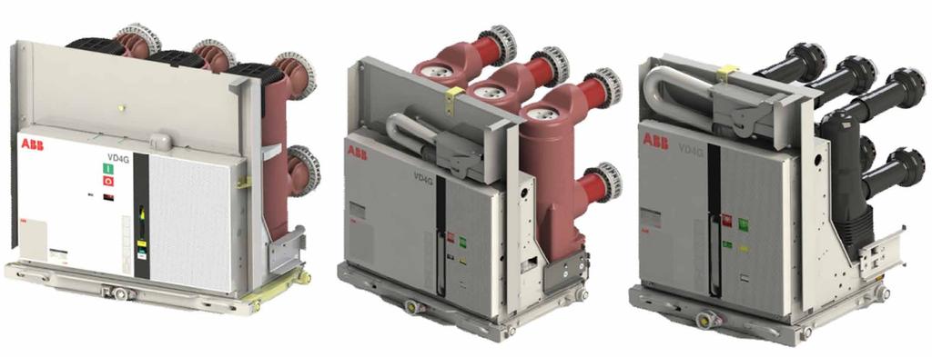
23 24 UNIGEAR ZS1 MEDIUM-VOLTAGE AIR-INSULATED SWITCHGEAR UP TO 24 KV UniGear ZS1 Vacuum circuit-breaker 01 VD4 circuit-breaker with mechanical actuator 02 VM1 circuit-breaker with magnetic actuator 03 VD4G circuit-breakers VM1 circuit-breaker The conventional mechanical stored energy type of operating mechanism used on the VD4 circuitbreakers can be replaced with an operating mechanism with magnetic actuator, creating the VM1 series of circuit-breakers. All the characteristics of the circuit-breakers described in this chapter remain unchanged except for the operating mechanism. The operating mechanism is based on a greatly reduced number of components: Actuator with permanent magnets. The heart of the operating mechanism consists of the magnetic actuator which carries out the closing and opening operations, and keeps the main contacts in their positions taken up after the operation. The magnet transmits the operating mechanism to the interrupters by means of a single transmission lever. Electronic control device. All the functions (trip, operation, energy charging and watchdog) are carried out by the integrated electronic controller. The circuit-breaker is fitted with a multivoltage direct and alternating current feeder. Capacitors. The energy required to switch the operating mechanism is provided by an incorporated capacitor bank. The stored energy guarantees the complete O-C-O reclosing sequence. Position sensors. The position of the circuitbreaker contacts is detected by means of electronic proximity sensors. Standards IEC for the circuit-breaker


24

25 26 UNIGEAR ZS1 MEDIUM-VOLTAGE AIR-INSULATED SWITCHGEAR UP TO 24 KV UniGear ZS1 VD4G Vacuum circuit-breaker for generator switching applications The worldwide increasing energy demand is covered more and more by decentralized power plants and renewable resources of small unit size. As the generated energy is fed into the grid by step-up transformers and MV distribution boards, VD4G offers a reliable and economical solution to protect the power plants assets. VD4G is the upgraded version of VD4 vacuum circuit-breaker for generator (GCB) applications. VD4G is suitable for the small power plants as well as for industrial, oil and gas applications in which generators are connected to the MV distribution of the plant. Protection Suitability analysis using grid calculation tool Optional system study for additional circuitbreakers in grid Fast interruption of system- and generator-fed short-circuit currents up to 50 ka Tested according to the latest edition of generator circuit-breaker standards including the IEC / IEEE Availability High TRV withstand capability Suitable for an increased DC component and longer arcing times More reliable synchronization More reliable supply for unit auxiliaries Flexibility Only one circuit-breaker shall be operated during the starting-up or shutting-down of generator Maintenance-free solution Compact solution Possible applications Renewable energy power plants Small energy power plants Networks with emergency power generator Process industry with own power generation Retrofit solutions Special requirements for suitability analysis with grid calculation tool ABB can provide you with adequate support for the suitability analysis and proper selection of GCB by providing the following information: Single Line Diagram Technical data sheet of generator, transformer and other grid equipment Technical data System- and generator-fed faults tested up to 50 ka High TRV withstand capability Suitable for switching under delayed current zero conditions Type tested according to Dual Logo IEC/IEEE covering also IEEE C Typical schematic of generator circuitbreaker application A B Generator Generator circuit-breaker Transformer Grid
26 27 The challenge to protect the grid as well as the generator against failures makes generator circuit-breakers essential. Each generator has specific technical characteristics. A suitability analysis of the generator circuitbreaker application is indispensable. The system-fed fault (A) and the generator-fed fault (B) of a grid need to be reliably interrupted by the generator circuit-breaker. A 60 System short-circuit current B 60 Generator short-circuit current Short-circuit current [ka] Short-circuit current [ka] Time [ms] IR(t) [ka] IS(t) [ka] IT(t) [ka] Time [ms] IR(t) [ka] IS(t) [ka] IT(t) [ka] Failure location A: System-fed fault Fast decaying DC component Failure location B: Generator-fed fault Slowly decaying and raised DC component results in delayed current zero Electrical characteristics according to IEC and IEC/IEEE Switchgear UniGear ZS1 with VD4G-25 Rated voltage [kv] 17.5 Maximum service voltage [kv] 15 Test voltage (50/60 Hz) [kv / 1 min] 38 Impulse withstand voltage [kv] 95 UniGear ZS1 with VD4G-40 Rated frequency [Hz] 50 / 60 UniGear ZS1 with VD4G-50 Rated short-time withstand current [ka / 3 s] Symmetrical short-circuit current Iscg Class G1 [ka] Symmetrical short-circuit current Iscg Class G2 [ka] Peak withstand current [ka] Internal arc withstand current [ka / 1 s] Rated current of the main busbars [A] Feeders rated current with natural ventilation [A] [A] [A] [A] Feeders rated current with forced ventilation [A] UniGear ZS1 panel with VD4G circuit-breaker can be coupled with standard UniGear ZS1 panel with VD4/P circuit-breaker
27 28 UNIGEAR ZS1 MEDIUM-VOLTAGE AIR-INSULATED SWITCHGEAR UP TO 24 KV UniGear ZS1 Gas circuit-breaker UniGear ZS1 switchgear can also be fitted with SF6 gas circuitbreakers. The ABB vacuum and gas series of circuitbreakers are mechanically interchangeable and the same switchgear unit can therefore take either type of apparatus. Only ABB can offer apparatus representing both techniques for the whole range of applications, voltage levels ( kv), rated current ( A) and breaking capacity ( ka). This makes it possible to specify the optimum solution for the installation characteristics and the feeders to be switched and protected. ABB s long practical experience shows that the two types of circuit-breakers are equally valid and complementary. HD4 circuit-breaker The HD4 medium voltage circuit-breakers use sulphurhexafluoride gas (SF6) to extinguish the electric arc and as the insulating medium. Thanks to the excellent properties of SF6 gas, interruption of the currents takes place without arc chopping and overvoltages. There is no restriking phenomenon after interruption and the dielectric properties following interruption are recovered extremely rapidly. Gas circuit-breakers are available for all electric power distribution applications. They are particularly recommended for use on capacitor banks, motors, transformers insulated in oil and in installations where components which are particularly sensitive to dielectric and dynamic stresses are installed (for example, old cables or transformers). Poles The HD4 circuit-breaker poles use the autopuffer breaking system, combining the compression and self-blast techniques in a single solution. The autopuffer system is the most innovative technique in the field of gas circuit-breakers and originates from high voltage apparatus. The combination of the compression and selfblast techniques allows the best performance to be obtained at all current values. Both techniques are always present, but whereas the former operates optimally in switching low currents, the latter acts effectively during operation at higher current values.the autopuffer technique allows the use of a smaller quantity of gas than that required by circuit-breakers based on other techniques. For the same reason, the gas pressure is also considerably reduced. The autopuffer technique guarantees the insulating withstand voltage and the breaking capacity up to 30% of the rated value, even with zero relative pressure.the whole range of HD4 circuit-breakers uses the same gas pressure for all rated voltage levels ( kv). SF6 gas pressure level monitoring is not necessary, since the circuitbreaker poles are sealed-for-life pressure systems and are maintenance-free. They are fitted with a pressure control device for checking that the characteristics are not altered due to transport or incorrect operations. Operating mechanism The HD4 circuit-breaker is fitted with a mechanical storedenergy operating mechanism. This is trip free and therefore allows opening and closing operations independent of the operator. The operating mechanism spring system can be recharged either manually or by means of a geared motor. The operating mechanism is of the same type for the whole series and has a standardised range of accessories and spare parts. All the accessory components can easily be replaced by means of plug-socket connectors. Opening and the closing of the apparatus can be carried out by pushbuttons on the front of the operating mechanism or by electric releases (shunt closing, shunt opening and undervoltage). The circuit-breakers are always fitted with an anti-pumping device to eliminate the possibility of simultaneous opening and closing commands, closing commands with springs discharged or with the main contacts not yet in their run-end position.

28 29 Truck The poles and operating mechanism are fixed onto a metal support and handling truck. The truck is provided with a wheel system which makes the operations for racking the apparatus out of and into the switchgear unit possible with the door closed. The truck allows effective earthing of the circuitbreaker by means of the metallic structure of the switchgear unit. Apparatus-operator interface The front panel of the circuit-breaker provides the userinterface. It features the following equipment: ON pushbutton OFF pushbutton Operation counter Indicator of the circuit-breaker open and closed state Indicator of the charged and discharged state of the operating mechanism springs Manual charging device for the operating mechanism springs Override selector of the undervoltage release (optional) LED gas pressure indicator (optional) HD4-HXA circuit-breaker for high unidirectional components The range of HD4 circuit-breakers is extended by the HD4-HXA version. This series of circuit-breakers maintains all the features described in this chapter, but is notable for its ability to switch loads with strong unidirectional components. For breaking capacities of 40 ka or lower, HD4- HXA circuit-breakers are able to switch loads with unidirectional components IDC = 100%, up to service voltage 13.8 kv; at 50 ka the unidirectional component percentage IDC is reduced to 50%. They can be used in all installations affected by strong unidirectional components, but their natural field of application is found in switching and protecting transformers of the auxiliary circuits in power generating stations. Standards IEC for the circuit-breaker IEC for the SF6 gas HD4 circuit-breaker
29 30 UNIGEAR ZS1 MEDIUM-VOLTAGE AIR-INSULATED SWITCHGEAR UP TO 24 KV UniGear ZS1 Vacuum contactor V-Contact VSC medium voltage contactors are apparatus suitable for operating in alternating current and are usually used to control feeders which require a high number of operations per hour. They are suitable for operating and protecting motors, transformers and power factor correction banks. Fitted with appropriate fuses, they can be used in circuits with fault levels up to 1000 MVA. The electrical life of V-Contact VSC contactors is defined as being in category AC3 with 100,000 operations (closing/opening), 400 A interrupted current. V-Contact VSC contactor The contactors consist of a monobloc of resin containing the following components: Vacuum interrupters Moving equipment Magnetic actuator Multivoltage feeder Accessories and auxiliary contacts The V-Contact contactors are provided in the following versions: VSC7/P for voltages up to 7.2 kv VSC7/PG for voltages up to 7 kv with 32 kv power frequency withstand voltage VSC12/P for voltages up to 12 kv VSC12/PG for voltages up to 12 kv with 42 kv power frequency withstand voltage Both versions are available with an operating mechanism with electrical or mechanical latching. The V-Contact VSC contactors are mechanically interchangeable with the former V-Contact V/P contactor and with the whole series of ABB circuit-breakers, the same switchgear unit can therefore take both types of apparatus without modification. A version of V-Contact VSC contactors is also used in the UniGear MCC compact switchgear up to 400 A. Operating mechanism Due to the magnetic actuator, V-Contact VSC contactors need negligible auxiliary power in all configurations (15 W inrush - 5 W continuous). The V-Contact VSC is available in three different configurations: SCO (single command operation). The contactor closes the supply of auxiliary voltage to the multivoltage feeder input, when the auxiliary is cut the contactor opens. DCO (double command operation). The contactor closes the supply of auxiliary voltage to the multivoltage feeder closing input and opens when opening input is supplied; anti pumping function is supplied as a standard. DCO configuration is also available, on request, with a delayed undervoltage function. This function enables automatic opening of the contactor when the auxiliary voltage level drops below IEC defined levels. Opening can be delayed from 0 to 5 seconds (customer setting by dip switches). All configurations are suitable for 1,000,000 mechanical operations. Fuses The contactor is fitted with medium voltage fuses for protection of the operated feeders. Coordination between the contactor, fuses and protection unit is guaranteed in accordance with the IEC The fuse-holder frame is usually preset for installation of a set of three fuses per phase with average dimensions and type of striker, according to the following standards: DIN BS 2692

30 31 The following fuses can be applied: DIN type with a length of 192, 292 and 442 mm BS type with a length of 235, 305, 410, 454 and 553 mm The fuse-holder frames are fitted with a device for automatic opening when even just one fuse blows. This same device does not allow contactor closing when even a single fuse is missing. The ABB range of fuses for transformer protection is called CEF, whereas CMF is for motors and capacitors. Standards IEC for the contactor IEC for the fuses Contactor VSC7/P VSC12/P Rated voltage [kv] Rated insulation voltage [kv] Rated power frequency withstand voltage [kv / 1 min] 20 (3) 28 (3) Rated lightning impulse withstand voltage [kv] Rated frequency [Hz] 50 / / 60 Rated short-time withstand current [ka] (1) Peak current [ka] Internal arc withstand current (2) [ka / 1s] Maximum rated current of the contactor [A] (1) Limited by the fuses (2) The internal arc withstand values are guaranteed in the compartments on the supply side of the fuses (busbars and apparatus) by the structure of the switchgear and on the load side (feeder) by the limiting properties of the fuses (3) VSC7/PG for 32 kv power frequency withstand voltage and VSC12/PG for 42 kv power frequency withstand voltage are available on request in a dedicated panel Maximum performances of the contactor with fuses 7.2 kv 12 kv Motors [kw] Transformers [kva] Capacitors [kvar] Maximum load currents of the fuses Feeder Transformers Motors Capacitors Rated voltage Fuse Maximum load Fuse Maximum load Fuse Maximum load 7.2 kv 200 A 160 A 315 A 250 A 355 A 285 A 12 kv 200 A 160 A 200 A 160 A 200 A 160 A V-Contact VSC contactor
31 32 UNIGEAR ZS1 MEDIUM-VOLTAGE AIR-INSULATED SWITCHGEAR UP TO 24 KV UniGear ZS1 Switch-disconnector UniGear panels can be fitted with ABB NAL type switch-disconnectors. These units are used to switch and protect feeders and transformers or the auxiliary services transformers in sub and power station. NAL-NALF switch-disconnector The NAL switch-disconnectors are medium voltage air-insulated apparatus consisting of a fixed support to which the post insulators are applied (top and bottom), the system of contacts (fixed and moving) and latching pliers (of the fuses or of the insulating bars). The switch-disconnector is fitted with two systems of moving blade contacts, the main one (through which the load current passes with the switch in the closed position) and the arcbreaking one (through which the current passes during the opening and closing operations). This solution means the main contacts are not stressed and therefore keeps the electrical characteristics of the apparatus unchanged. During switch-disconnector opening air is compressed by the pistons contained in the top insulator cylinders. At the moment of opening and separation of the contacts, a blast of compressed air is emitted through special nozzles, so the arc is cooled and deionised. This leads to a gradual increase in the arc resistance which causes its extinction. The movement of the pistons is synchronised with the arc-breaking contacts of the switch-disconnector -this guarantees the highest inflow of air at the moment of separation of the contacts and there by ensures reliable arc extinction. The unit can be fitted with insulating bars (NAL switch-disconnector unit) or with medium voltage fuses (NALFswitch-disconnector unit with fuses). The NALF switch-disconnector is fitted with an automatic release mechanism for fuse tripping and uses fuses in accordance with DIN Standards. The ABB range of fuses for transformer protection is CEF. Each unit is fitted with an earthing switch with making capacity 16 ka for earthing the cables. Switch-disconnector control, like that of the earthing switch, is carried out manually from the switchgear front panel. The position of both items of apparatus can be seen directly from the front of the switchgear through an inspection window. The switchgear panel can be fitted with a set of three current transformers or with measurement sensors. The Disconnector Feeder unit (DF) consists of two power compartments: busbars and switchdisconnector/cables.the latter contains both the switch-disconnector and the connection terminals of the power cables. Segregation between the power compartments takes place automatically with earthing switch closure. An insulating shutter creates complete separation between the fixed contacts of the switch-disconnector, making the top ones inaccessible to the operators. This makes maintenance operations on the cables and fuses possible, keeping the remainder of the switchgear in operation. UniGear ZS1 panel with fixed switch-disconnector is classified LSC-2A because the cable and apparatus compartments are not phisically segregated. The switch-disconnector, earthing switch and access door to the cables compartment are interlocked with each other to guarantee maximum safety for the personnel and correct operation. Each switchgear panel is fitted with an auxiliary compartment, where the instruments and auxiliary cabling are housed. All the switchgear panels are accessible from the front and maintenance and service operations can therefore be carried out even when the switchgear is wall-mounted. Standards IEC for the switch-disconnector IEC for the fuses
![33 Rated voltage [kv] 12 17.5 24 Rated insulation voltage [kv] 12 17.](/docs-images/95/123348048/images/32-0.jpg "5 24 Rated power frequency withstand voltage ( 1 ) [kv / 1 min] 28 38 50 Rated lightning impulse withstand voltage [kv] 75 95 125 Rated frequency [Hz] 50/60 50/60 50/60 (1) GB/DL version is available")
32 33 Rated voltage [kv] Rated insulation voltage [kv] Rated power frequency withstand voltage ( 1 ) [kv / 1 min] Rated lightning impulse withstand voltage [kv] Rated frequency [Hz] 50/60 50/60 50/60 (1) GB/DL version is available with higher request in dielectric characteristics NALF switch-disconnector unit with fuses Rated short-time withstand current of switch-disconnector 1s ( 1 ) [ka] Peak current [ka] Maximum rated current of the fuses [A] Internal arc withstand current ( 2 ) [ka / 1 s] (1) Limited by the fuses (2) The internal arc withstand values are guaranteed in the compartment on the supply side of the fuses (busbars) by the structure of the switchgear and on the load side (cables) by the limiting properties of the fuses Selection table of the fuses for protection transformers Transformer rated voltage [kv] Transformer rated output [kva] CEF Fuse-link In [A] Fuse rated voltage [kv] The table was calculated according to standards IEC and IEC (for operating voltages up to 24 kv). The following transformer work conditions were assumed: Maximum long-lasting overload 150% Magnetizing inrush current 12 In during 100 ms Transformer short-circuit voltage according to IEC Standard ambient working conditions of fuses The table above details the rated current of a particular fuse link for a given line voltage and transformer rating. For different criteria, the fuse selection must be recalculated. The given limits of the rated current of fuse are not mandatory for use in the NALF disconnector / NAL without fuse tripping system. Rated current values of the corresponding fuses for these applications are given in the ABB catalogue FUSES. 3.6/ NALF switchdisconnector
33 34 UNIGEAR ZS1 MEDIUM-VOLTAGE AIR-INSULATED SWITCHGEAR UP TO 24 KV UniGear ZS1 Service trucks The UniGear ZS1 range is equipped with all the service trucks needed for service maintenance activities. The trucks are divided into four different types: Earthing without making capacity Earthing with making capacity Cable test Isolation Earthing truck without making capacity These trucks carry out the same function as the earthing switches without making capacity. They therefore have no capacity to earth live circuits in fault conditions. They are used to ensure an additional fixed earth, as is required by certain installation service and maintenance procedures, as a further safety guarantee for personnel. The use of these trucks require the removal of the apparatus (circuit-breaker or contactor) from the switchgear and its replacement with the truck. The switchgear panels preset for use of the earthing trucks must be provided with a key lock which, when activated, prevents their racking-in. This truck is available in two versions: Earthing of the main busbar system Earthing of the power cables The earthing truck of the main busbars, during the racking-in phase, only lifts the top shutter and earths the contacts connected to the top branch connections (and therefore to the main busbar system) by means of the switchgear structure. The earthing truck of the power cables, during the racking-in phase, only activates the bottom shutter and earths the contacts connected to the bottom branch connections (and therefore to the power cables) by means of the switchgear structure. These trucks can also be used in the bus-tie unit. In this case, they earth one of the two sides of the main busbar system. Earthing truck with making capacity These trucks carry out the same function as the earthing switches with making capacity. They consist of circuit-breakers provided with top (earthing of the main busbars) or bottom (earthing of the power cables) terminals only. The contacts without terminals are short-circuited by means of a copper bar and connected to earth by means of the apparatus truck. They keep all the characteristics of the circuitbreakers, such as full making and breaking capacity on live circuits under fault conditions. They are used to ensure extremely effective earthing on circuits stressed by a fault. They allow opening and closing operations to be carried out rapidly with electric remote control. The use of these trucks require the removal of the apparatus (circuit-breaker or contactor) from the switchgear and its replacement with the truck. The switchgear panels preset for use of the earthing trucks must be provided with a key lock which, when activated, prevents their being racked-in. This truck is available in two versions: Earthing of the main busbar system Earthing of the power cables The earthing truck of the main busbars, during the racking-in phase, only lifts the top shutter and presets the contacts connected to the top branch connections (and therefore to the main busbar system) for closing to earth by means of operating mechanism. The earthing truck of the power cables, during the racking-in phase, only activates the bottom shutter and presets the contacts connected to the bottom branch connections (and therefore to the power cables) for closing to earth by means of operating mechanism. These trucks can also be used in the bus-tie unit. In this case, they earth one of the two sides of the main busbar system.
34 35 Power cable test truck These trucks allow the insulation tests on the power cables to be carried out without accessing the feeder compartment or disconnecting the cables from the switchgear. The use of these trucks require the removal of the apparatus (circuit-breaker or contactor) from the switchgear and its replacement with the truck. The truck, during the racking-in phase, only activates the bottom shutter and, by means of the connectors it is fitted with, allows connection of the test apparatus cables. This truck can only be used in the incoming/ outgoing feeders with the door open. Isolating truck The isolating truck allows the top switchgear contacts to be connected directly to the bottom ones. Connection is made extremely safe by using the poles of the circuit-breakers to insulate the connection busbars from the external environment. In the incoming/outgoing feeder units it connects the main busbar system to the power cables, whereas in the bus-tie, to the two sides of the busbar system. This truck has its application in UniGear switchgear for making incoming/outgoing feeders without a circuit-breaker in radial networks, for making cable connections between two items of switchgear placed in front of each other, in making interconnection units and in creating the bus-tie riser configuration with double insulation (in this case, both the units are made up of bus-ties, the former fitted with a circuit-breaker and the latter with an isolating truck). The switchgear panels preset for use of the isolating trucks must be fitted with a key lock which, when activated, prevents their being racked-in. Main busbar system earthing truck, without making capacity. Power cable earthing truck, without making capacity. Cable test truck. Main busbar system earthing truck, with making capacity. Power cable earthing truck, with making capacity. Isolating truck.


35 36 UNIGEAR ZS1 MEDIUM-VOLTAGE AIR-INSULATED SWITCHGEAR UP TO 24 KV UniGear ZS1 Ultra Fast Earthing Switch The Ultra-Fast Earthing Switch (UFES) is an innovative design of an active arc protection device which effectively mitigates the severe mechanical and thermal impacts caused by internal arc faults. The UFES is a combination of devices consisting of an electronic unit and the corresponding primary switching elements which initiate a three-phase earthing in the event of an arc fault. With operating times of less than 4 ms after detection UFES clears an internal arc fault almost immediately after it arises. Thus arc impacts are reduced to an absolute minimum and safety standards raised to a whole new level. The UFES is available to fulfil a variety of applications in the UniGear ZS1 switchgear e.g.: Busbar installation with top-housing box Cable compartment installation Unbeatable advantages in case of an arc fault event: Drastic reduction of repair costs: no damages on the switchgear equipment to be expected. No exchange of the faulty panel. Greatly increased system availability: after inspection and elimination of the fault reason the switchgear can be taken into service again within shortest possible time. Greatly increased operator safety for human mal-operation under maintenance conditions Minimized secondary effects like light/sound emission or the release of toxic gases Solution for pressure sensitive environment with limited pressure relief options Electrical maximum characteristics in UniGear ZS1 Rated insulation voltage (rms) ( 1 ) [kv] Rated power frequency withstand voltage (rms) [kv] Rated lightning impulse withstand voltage (peak) [kv] Rated frequency [Hz] 50 / / / 60 Rated short-time withstand current (rms) ( 1 ) [ka] Rated short-circuit making current [ka] Rated duration of short-circuit [s] ( 1 ) GB/DL version is available with higher request in dielectric characteristics (42 kv) and short-time withstand current (4 s) UFES kit; Primary switching element installed in the cable compartment
36 37 I(t) Overpressure in bar Time in ms t Time in ms TC + < 4 ms Short-circuit current I n DC component Pressure curve with UFES (4 ms) Pressure curve without UFES t TC Arcing time with UFES Final clearing of fault current by upstream circuit-breaker - 80 ms + timex Reaching time for tripping criteria t TC Reaching time for tripping criteria In rare cases, failure inside a switchgear cubicle due either to a defect, an exceptional service condition or mainly by human mal-operation may initiate an internal arc. The faster the arc will be interrupted, the less destruction on the switchgear equipment will occur. Avoidance of the severe effects of an internal arc fault, such as - Rapid temperature rise (up to 20,000 C) - Rapid pressure rise (see figure) - Burning of materials by fastest possible extinction CB CB CB CB CB CT CT CT CT CT I k I k I k I k I k UFES QRU UFES QRU UFES QRU UFES QRU UFES QRU (Optional) I(t) I(t) I(t) I(t) I(t) Time in ms Time in ms Time in ms Time in ms Time in ms Event sequence description 1. Internal arc formation 2. Arc detection by the electronic device (light and current) 3. ~ 1-2 ms after detection: Tripping signal to the UFES primary switching elements 4. ~ 3-4 ms after detection: Bolted 3-phase earthing by operation of the UFES primary switching elements - Interruption of the arc voltage: Immediate extinction of the arc - Controlled fault current flow via UFES primary switching elements to earth potential 5. Final clearing of the fault current by the upstream circuit-breaker
37 38 UNIGEAR ZS1 MEDIUM-VOLTAGE AIR-INSULATED SWITCHGEAR UP TO 24 KV UniGear ZS1 I S -limiter: fault-current limitation Short-circuit currents too high? The I S -limiter, a switching device with extremely short operating time, solves the problem. The rising global demand for energy requires more powerful or additional transformers and generators, and an increasing interconnection of the individual supply networks. This can lead to the permissible short-circuit currents for the equipment being exceeded causing severe dynamic or thermal damage or even complete destruction. The replacement of existing switchgear and cable connections by new equipment with a higher short-circuit strength is often technically impossible or uneconomical for the user. The use of I S -limiters reduces the short-circuit current in both new systems and expansions of existing systems, thus saving cost. A short-circuit downstream from an outgoing feeder breaker is assumed. The oscillogram shown below indicates the course of the shortcircuit currents in the first half wave. A short-circuit current of 31.5 ka can flow to the fault location through each transformer. This would result in a total short-circuit current of 63 ka, which is twice as much as the switchgear capability. The course of the current through the I S -limiter in such an event is shown below as current i 2. It can be seen that the I S -limiter operates so rapidly, that there is no contribution via the transformer T2 to the total peak short-circuit current (i 1 + i 2 ). Therefore, a switchgear with a rating of 31.5 ka is suitable for this application. Technical Data Rated voltage [kv] / 40.5 Rated current [A] / / / / ) / / / / ) / / / ) / ) / / ) Interrupting current [ka RMS ] Up to 210 Up to 210 Up to 140 Up to 140 1) with cooling fan Single line diagram of a bus tie for a system with l n = 31.5 ka and with k an l S -limiter; I S -limiter application diagram T1 l n = 31.5 ka k ln T2 = 31.5 ka k 160 ka i i = i 1 + i 2 whithout I s -limiter l = l 1 + l 2 l 1 l 2 l n = 31.5 ka k perm. 80 ka (31.5 ka x H x 2) Current i = i 1 + i 2 at the fault location l 1 i = i 1 + i 2 with I s -limiter l 2 t
38 39 Potential applications Such a fast switching device caters for a variety of applications which cannot be fulfilled by conventional switches. The most important of these are presented below. Advantages of all I S -limiter applications: Reduction of short-circuit currents at the fault location No upgrading of the existing switchgear Option A Coupling-parallel operation of two systems. Advantages: Improving power quality Increasing the reliability of the system Reduction of the network-impedance Optimal load flow Option B I S -limiter in the generator feeder to protect the high voltage system. Advantages: Generator can be connected independent of the short-circuit capability of the system Existing busbar system does not need to be changed No need for expensive generator breaker Option C I S -limiter and reactor connected in parallel. Advantages: Avoid copper losses of the reactor Avoid voltage drop over the reactor No electro-magnetic field of the reactor Option D Station service supply and public network. Advantages: Private/industrial generator feeder can be connected to the (fully loaded) grid Selective tripping of the I S -limiter (I S -limiter will operate only for short-circuit faults in the grid) Option E If in the case of two IS-limiters being installed in a switch-board selective tripping is required, a measurement of the total current becomes necessary. Advantage: The I S -limiter trips as follows: Short-circuit in section A: Only I S -limiter no. 1 trips Short-circuit in section B: I S -limiter no. 1 and no. 2 trip Short-circuit in section C: Only I S -limiter no. 2 trips 31.5 MVA 12% 110 kv Option B 40 MVA 8% I ıı = 15 ka kt 10 kv/25 ka 10 kv/31.5 ka 10 kv/40 ka Option A Option C 10 kv/16 ka Option D I ıı kg = 3 ka Three possible applications of I S -limiters in one figure (Option A, B, C) I S -limiter in connecting point with a public supply network (Option D) T1 T2 T3 I T1 I T2 I T3 I S-1 I S-2 A B C Use of more than one I s -limiter with selectivity (Option E)
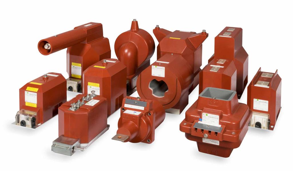
39 40 UNIGEAR ZS1 MEDIUM-VOLTAGE AIR-INSULATED SWITCHGEAR UP TO 24 KV UniGear ZS1 Instrument transformers 01 Current transformer TPU 02 Voltage transformer TJC 03 Current and voltage transformers Block type current transformers The block type current transformers are epoxy resin insulated and used to supply the measurement devices and protection instruments. These transformers can have a wound core or a bushing bar with one or more cores, with performance and accuracy classes suitable for the installation requirements. They conform to the IEC , IEC which have fully replaced previous standard IEC Their dimensions are in accordance with the DIN Standard, in the Medium and Long Size versions up to A, where they are of the toroidal type in the range of currents from A to A (KOKS type). The current transformers can also be provided with a capacitive socket for connection to voltage signalling devices. The current transformers are normally fitted on the load side of the apparatus compartment for measurement of the phase currents of the switchgear unit. Fitting on the supply side of the apparatus compartment is also possible (busbar applications) for measuring the busbar currents or for realising particular protection schemes. The ABB range of current transformers is designated TPU. They conform to the IEC , IEC which have fully replaced previous standard IEC Their dimensions are in accordance with the DIN Standard. These transformers can have one or two poles, with performance and precision classes suited to the functional requirements of the instruments connected to them. When they are installed on removable or withdrawable trucks they are fitted with medium voltage protection fuses. The withdrawable trucks also allow replacement of the fuses with the switchgear in service. Truck racking-out with the door closed automatically operates closure of a metallic segregation shutter between the live parts of the switchgear and the instrument compartment. Fixed voltage transformers can be installed directly on the main busbar system in a dedicated compartment (busbar applications). The ABB range of voltage transformers is designated TJC, TDC, TJP. Ring core current transformers The toroidal transformers are of the epoxy resin insulated type and are used to supply measurement and protection devices. These transformers can feature either a closed or openable core. They can be used both for measuring phase currents or for detecting the earth fault current. They conform to the IEC , IEC which have fully replaced previous standard IEC Voltage transformers The voltage transformers are of the epoxy resin insulated type and are used to supply measurement and protection devices. They are available for fixed assembly or for installation on removable and withdrawable trucks.


40
41 42 UNIGEAR ZS1 MEDIUM-VOLTAGE AIR-INSULATED SWITCHGEAR UP TO 24 KV UniGear ZS1 Current and voltage sensors The sensor technology has been used in ABB since the beginning of the 1990s and there are more than sensors installed and operating to date. Sensors based on advanced measurement principles have been developed as successors to conventional instrument transformers in order to achieve significant reduction in dimensions, increase of safety and to provide greater rating standardization with a wider functionality range. Conventional instrument transformers with magnetic cores are based on well-known principles that have been utilized with all their advantages as well as limitations for more than 120 years. However the connected equipment (protection relays) has significantly changed during the last 20 years. New protection relays place different requirements on primary measurement equipment (instrument transformers) compared to classic electromechanical relays. These new requirements also open up the opportunity for the utilization of advanced measurement principles that offer a wide range of additional benefits. Sensors open up a way for current and voltage signals needed for the protection and monitoring of medium voltage power systems. These advantages can be fully used in connection with modern protection relays. Energy savings solution The sensor technology means no transfer of power from the primary to the secondary side, which means negligible power losses. Therefore, the sensors exhibit extremely low energy consumption the value of which is just a fraction of what is converted into heat in a conventional instrument transformer. This fact contributes to significant energy savings during the system s entire operating life, supporting world-wide efforts to reduce energy consumption. Easy switchgear integration solution Since the sensor elements are particularly small and the same elements are used for both measurement and protection, the current and voltage sensors can easily be integrated in the switchgear. These facts enable the sensors to be designed in a highly optimal way, which contributes to a high level of switchgear simplification. Sensor characteristics ABB current and voltage sensors are designed without the use of a ferromagnetic core. The current sensor is based on the principle of Rogowski coil, voltage sensor uses the principle of resistive voltage divider. Sensor technology brings several important benefits for the user and the application. The main benefit is that the behavior of the sensor is not influenced by magnetizing curve which results in a highly accurate and linear response across a wide dynamic range of measured quantities. The linear and highly accurate characteristic curve of the sensor across its full operating range enables several metering and protection classes to be combined in one particular winding.
42 43 Indoor current sensors Current measurement in KECA sensors is based on the Rogowski coil principle. KECA 80 C104 / KECA 80 C165 For dynamic current measurement (protection purposes) the ABB sensors KECA 80 C104, and KECA 80 C165, fulfill requirements of protection class 5P up to an impressive value reaching the rated short-time thermal current Ith (31.5 ka or 50 ka). With KECA 80 C104 and KECA 80 C165 sensors, measuring class 0.5 is reached for continuous current measurement in the extended accuracy range from 5 % of the rated primary current Ipr not only up to 120 % of Ipr (as being common for conventional current transformers), but even up to the rated continuous thermal current Icth (1 250 A or A). That provides the possibility to designate the corresponding accuracy class as 5P400 and 5P630, proving excellent linearity and accuracy measurements. Technical parameters Continuous thermal current: / A Rated primary current: 80 A / Hz Rated primary current: 80 A / Hz Accuracy class: 0.5 / 5P400; 0.5 / 5P630 KECA 80 C184 / KECA 80 C216 For dynamic current measurement (protection purposes) the ABB sensors KECA 80 C184, and KECA 80 C216, fulfill requirements of protection class 5P up to an impressive value reaching the rated short-time thermal current Ith (31.5 ka). With KECA 80 C184 and KECA 80 C216 sensors, measuring class 0.5 is reached for continuous current measurement in the extended accuracy range from 5 % of the rated primary current Ipr not only up to 120% of Ipr (as being common for conventional current transformers), but even up to the rated continuous thermal current Icth (1 250 A or A). That provides the possibility to designate the corresponding accuracy class as 5P400, proving excellent linearity and accuracy measurements. Technical parameters Continuous thermal current: / A Rated primary current: 80 A / Hz Rated primary current: 80 A / Hz Accuracy class: 0.5 / 5P400 Performance comparison between conventional current transformer and current sensor Secondary output 1 1 Us ABB sensor Saturation level 2 2 Standard CT is 10 A 100 A A A Primary current
43 44 UNIGEAR ZS1 MEDIUM-VOLTAGE AIR-INSULATED SWITCHGEAR UP TO 24 KV UniGear ZS1 Current and voltage sensors 01 Current sensors KECA 80 C104 / KECA 80 C Voltage sensor KEVA 17.5 B20 03 Combined sensors KEVCD Indoor voltage sensors Voltage measurement in the KEVA sensor is based on the resistive divider principle. KEVA 17.5 B20 KEVA B sensor can be used in all applications up to the voltage level 17.5 kv. The sensor fulfills requirements of accuracy class 0.5 for measurement purposes and accuracy class 3P for protection purposes. Combined sensors Current & voltage measurements and voltage indication integrated in the same compact cast resin part. KEVCD The combined sensors type KEVCD are intended for use in current and voltage measurements in air insulated switchgear. KEVCD are block type sensors designed according to the DIN size requirements. Technical parameters Rated primary voltage: 15/ 3 kv Rated power frequency withstand voltage: 38 (42) kv Rated lightning impulse withstand voltage: 95 kv Transformation ratio: :1 Accuracy class: 0.5 / 3P Technical parameters KEVCD A Continuous thermal current: A Rated primary current: 80 A / Hz Rated primary current: 80 A / Hz Current accuracy class: 0.5 / 5P630 Voltage accuracy class: 0.5 / 3P KEVA 24 B20 KEVA B sensor can be used in all applications up to the voltage level 24 kv. The sensor fulfills requirements of accuracy class 0.5 for measurement purposes and accuracy class 3P for protection purposes. Technical parameters Rated primary voltage: 22/ 3 kv Rated power frequency withstand voltage: 50 kv Rated lightning impulse withstand voltage: 125 kv Transformation ratio: :1 Accuracy class: 0.5/3P Technical parameters KEVCD B Continuous thermal current: A Rated primary current: A / Hz Rated primary current: A / Hz Current accuracy class: 1 Voltage accuracy class: 1 / 3P

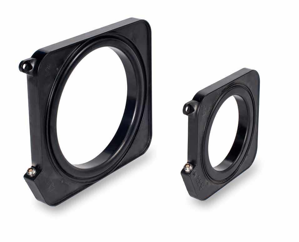
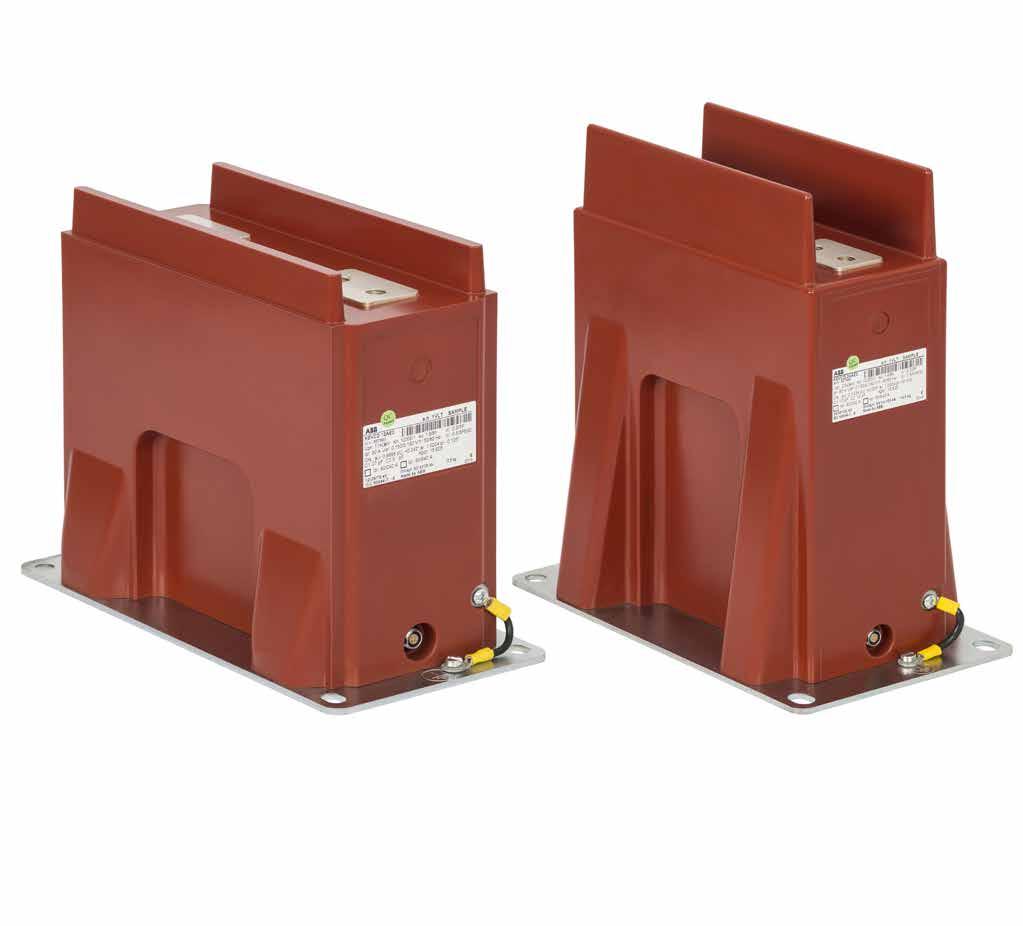
44
45 46 UNIGEAR ZS1 MEDIUM-VOLTAGE AIR-INSULATED SWITCHGEAR UP TO 24 KV UniGear ZS1 Cable terminations 01 ABB Kabeldon cable termination type SOT 10 with bi-metallic cable lug type SKSB 02 ABB Kabeldon cable termination type SOT 24 with bi-metallic cable lug type SKSB Terminations for polymer insulated cables 1 24 kv It is crucial that power cables connecting the switchgear are terminated properly, and for this purpose, ABB has developed an excellent range of easy-to-use products for preparation and termination of cables. MV power cables are normally designed with a conductor of aluminium or copper, an insulation of polymer material, an extruded insulation screen, a metallic screen, armouring (optional) and a polymeric outer jacket. To enable safe and reliable current carrying properties, it is necessary to achieve sufficient mechanical connection between the cable conductor and the bus bar. ABB offers mechanical cable lugs designed to fit the cable conductor by bolting. It is also essential to guide the electrical field of the cable correctly, and ABB offers Cold Applied terminations, made of rubber, that create an active pressure around the cable. Furthermore, if the cable is designed with another type of metallic screen than copper wires, special earthing kits must be used to achieve proper handling of possible fault currents. The armouring of the cable must have the same earth potential as the cable screen, so it might be necessary to use additional connection accessories that are also available. Detailed information can be found in separate technical information for cable accessories. Applications and features Depending on the cable design, it is necessary to use the correct type of cable accessory. When single core cables are designed with copper wire screen only, it is sufficient to use just a cable lug and a termination that fits the actual size of the cable. The benefit of Cold Applied accessories is that no heat or open flame is necessary for installation (except for branch seals on 3-core cables). After the cable is prepared, the termination is simply slid on without any tools. If a three core cable is used, or a cable with copper tape screen, or aluminium foil screen, or a cable with armouring; then additional material is required. Another very important factor is correct cable preparation, and ABB also offers excellent cable preparation tools. Recommended cable termination products The pre-moulded cable termination type Kabeldon SOT can be used on any polymer cable irrespective of design or conductor size. Type SOT 10 is designed for 7.2 kv cables, while type SOT 24 covers 12, 17.5 and 24 kv. A few variants of terminations fit a wide range of cable sizes. Extra material such as earthing kits, crutch seals for 3-core cables and screen potential material for cable armouring is also covered by the ABB range of products. Please contact your ABB Sales Representative for more information.
![47 01 02 Designation and sizes Voltage level [kv] Designation Kabeldon Diameter over insulation [mm] Conductor size [mm²] 7.2 kv 12 kv 17.5 kv 24 kv 1-7.2 SOT 101 10.5-15 10-35 - - - 1-7.2 SOT 102 12.](/docs-images/95/123348048/images/46-0.jpg "9-25.8 50-150 - - - 1-7.2 SOT 103 21.4-34.9 185-300 - - - 12-17.5 SOT 241 A 11-15 - 10-35 - - 12-17.5 SOT 241 15-28 - 50-185 50 150-12 - 17.5 SOT 242 24-39 - 240-500 185-300 - 24 - - - - - - 12-17.")
46 Designation and sizes Voltage level [kv] Designation Kabeldon Diameter over insulation [mm] Conductor size [mm²] 7.2 kv 12 kv 17.5 kv 24 kv SOT SOT SOT SOT 241 A SOT SOT SOT 242 B (*) 630 (*) - 24 SOT 241 A SOT SOT SOT 242 B (*) (*) Can be mounted on cables with 800 and 1000 mm 2 by using silicone rubber tape 2342 as top seal
47 48 UNIGEAR ZS1 MEDIUM-VOLTAGE AIR-INSULATED SWITCHGEAR UP TO 24 KV UniGear ZS1 Distribution automation ABB s power protection philosophy Having delivered protection relays to more than 100 countries, ABB fully understands the need for diverse protection philosophies that meet local legislation, safety requirements and engineering practice. Therefore, ABB has developed a power protection philosophy that not only serves the specific needs and requirements of diverse power systems, but also creates confidence and peace of mind for both the power system owners and users. The main purpose of a protection relay system is to recognize any abnormal power system condition(s), or abnormally operating system component(s). Based on the information gathered, the protection system will initiate corrective actions that return the system to its normal operating state. This provides a safe environment for all. Protection relays are activated when something abnormal has happened in the power system; they do not prevent network faults from arising. Selecting the right protection functions and methods improves the performance and the reliability of the protection system, thus minimizing the effects of network faults and preventing the disturbance from spreading to the healthy parts of the network. Advantages of a complete protection system Close attention must be paid to operating speed, sensitivity, selectivity and reliability of the protection system. There is a strong correlation between the operating speed of the protection system and the damage and danger caused by a network fault. Substation automation provides remote control and monitoring capabilities, which speed up the location of faults and the restoration of the power supply. Fast operation of the protection relays also minimizes post-fault load peaks. Together with voltage dips, post-fault load peaks increase the risk of the disturbance spreading to healthy parts of the network. The sensitivity of the protection must be adequate to detect relatively high resistance earth faults and short-circuits in the most distant parts of the network. Reliable selectivity is essential to limit the loss of power supply to as small a part of the network as possible, and to allow the faulted part of the network to be reliably located. Corrective actions can then be directed to the faulty part of the network, so that the power supply can be restored as quickly as possible. The protection system must have a high degree of reliability. This also means that if, for example, the circuit breaker (CB) fails to operate, the back-up protection will clear the fault. Substation automation (SA) puts the operator in complete control of the substation. In addition, SA improves the power quality of the transmission and distribution network under normal operation, but especially in a disturbance situation and during substation maintenance activities. An SA or SCADA brings the full benefits of digital technology into protection and control of the networks. The protection relays are easily set-up and parameterized through easy and safe access from the operator s workplace.

48
49 50 UNIGEAR ZS1 MEDIUM-VOLTAGE AIR-INSULATED SWITCHGEAR UP TO 24 KV UniGear ZS1 Distribution automation Relion protection and control relays The Relion product family offers the widest range of products for the protection, control, measurement and supervision of power systems for IEC and ANSI applications from generation and interconnected transmission grids over primary distribution to secondary distribution kiosks. The Relion protection relays are deeply rooted in ABB s vast experience of developing successful protection and control relays. These relays have been developed during many years and are built on the experience gathered from wide ranging application and functionality requirements of ABB s customers globally. To ensure interoperable and future-proof solutions, Relion products have been designed to implement the core values of the IEC standard. The genuine implementation of the IEC substation modelling and communication standard covers both vertical and horizontal information exchange between protection relays and external systems. The protection and control IED manager PCM600 provides versatile functionality throughout the life cycle of all Relion protection and control relays. PCM600 is IEC compliant, which ensures smooth engineering of the relays and enables information exchange with other IEC compliant tools. With these products, you benefit from ABB s leading-edge technology, global application knowledge and experienced support network. The Relion technology is leading the way and setting the future trends in the field of protection and control systems. Relion 605 series The Relion 605 series protection relays feature basic devices that fulfill the essential protection needs in medium-voltage networks. The series is best suited for secondary distribution applications. These relays are well-known for their straight forward approach to protection. Relion 611 series The Relion 611 series protection relays are powerful and very easy-to-use protection devices in a compact design. The 611 series relays are delivered with a pre-configured application, which can be adapted, to a limited extent, to application-specific needs. The series offers preconfigured solutions, which are ideally suited for utility distribution and industrial applications. Relion 615 series The Relion 615 series protection relays can be defined as a compact and versatile solution for power distribution in utility and industrial applications. The 615 series provides standard configurations, which allows you to easily adapt and set-up your applications, still allowing you to adapt the configuration according to applicationspecific needs. The 615 series combines compactness and powerful features in one smart package. Relion 620 series The Relion 620 series protection relays increase flexibility in demanding utility and industrial applications for power distribution. They are delivered with example configurations to ease adaptation into your specific applications. The series offers customization possibilities, which supports higher levels of standardization in the applications. The 620 series extends the hardware possibilities further compared to the 615 series.


50 51 01 Relion protection and control product family Relion 630 series The pre-configured Relion 630 series protection relays feature flexible and scalable functionality to adapt to different needs in power distribution networks and industrial applications. The 630 series protection relays contain pre-configured application configurations, which can be freely tailored to meet specific requirements for distribution applications. Relion 650 series The Relion 650 series offers ease of use from ready-to-use solutions. The 650 series protection relays provide optimum off-the-shelf solutions. These relays are equipped and configured with complete protection functionality and default parameters to meet the needs of a wide range of applications within generation, transmission and sub-transmission. Relion 640 REX640 makes protecting all your assets in advanced power generation and distribution applications easy. The fully modular design allows unequaled customization and modification flexibility, and easy adaptation to changing protection requirements throughout the relay life cycle. This is asset management at its best. Please see dedicated chapter on page 64. Relion 670 series The Relion 670 series protection and control relays provide versatile functionality, as well as maximum flexibility and performance to meet the highest requirements of any application in generation, transmission and sub-transmission protection systems. The 670 series relays are available as pre-configured and fully customized relays. 01
51 52 UNIGEAR ZS1 MEDIUM-VOLTAGE AIR-INSULATED SWITCHGEAR UP TO 24 KV UniGear ZS1 Distribution automation Feeder protection Feeder protection, or more exactly protection for overhead lines and cables, is the most used type of protection in power systems. The protection has to ensure that the power grid continues to supply energy. In the event of a fault, it has to be prevented from spreading to healthy parts of the network. The relays also have to minimize the damage to the cables and other connected equipment, as well as ensure safety for operating personnel. ABB has a large number of feeder protection relays. There are several multifunctional protection relays for different application ranges. Among the protection relays there are some used for general feeder protection (protection against overcurrent) and as back-up protection. There are also more specialized relays, for example, for line differential protection. The selected protection scheme has to fulfill the application specific requirements regarding sensitivity, selectivity and operating speed. The protection requirements are mainly determined by the physical structure of the network. In most cases the requirements, listed above, can be fulfilled with non-directional/directional overcurrent protection functions. In power networks with a more complex structure, more advanced protection functions, such as, distance protection or line differential protection, may have to be introduced. The purpose of the over and undervoltage protection system is to monitor the network s voltage level. If the voltage level deviates from the target value by more than the permitted margin for a specific time period, the voltage protection system limits the duration of the abnormal condition and the stresses caused to the power system or its components. To prevent major outages due to frequency disturbances, sub-stations are usually equipped with underfrequency protection relays, which in turn, control various load-shedding schemes. A specific area for applying line differential protection is emerging with feeder applications requiring an absolutely selective unit protection system. The zone-of-protection for a line differential protection system is the feeder section, defined by the location between the current measurement devices (current transformers or Rogowski coils). In certain cases there can be a power transformer within the protection zone. Unit protection guarantees exact and fast isolation of the fault and allows continued operation of the unaffected part of the power network. These are just a few examples of the major protection functions for feeders. More details can be found in the technical documentation available online for ABB s protection and control devices. Product offering The recommended products for feeder protection are part of ABB s Relion product family. The Relion product family offers the widest range of products for the protection, control, measurement and supervision of power systems for IEC and ANSI applications. Relion 605 series The Relion 605 series protection relays feature basic devices that fulfill the essential protection needs in medium-voltage networks. These relays are well-known for their straight forward approach to protection. Relion 611 series The Relion 611 series offers a pre-configured solution for power distribution in utility and industrial applications. The series is a suitable choice for protection and control of standard feeders. The protection relays are delivered preconfigured for easier and faster relay engineering and shorter time-to-operation. Relion 615 series The Relion 615 series offers a compact and versatile solution for power distribution in utility and industrial applications. The protection relays are delivered with a standard configuration for easier and faster relay engineering and shorter time-to-operation.


52 53 01 Basic range: Feeder protection REF601 and self-powered feeder protection REJ Medium range: Feeder protection and control REF611, Feeder protection and control REF High range: Feeder protection and control REF620, Feeder protection and control REF Multiapplication Protection and Control REX640 Relion 620 series The Relion 620 series offers flexibility and performance for demanding power distribution in utility and industrial applications. The series offers wider application coverage in one product compared to the 615 series, which enables wider standardization of the product type in your application. The 620 series protection relays are delivered with an example configuration, which helps adaptation to user specific requirements. Relion 630 series The Relion 630 series protection relays feature flexible and scalable functionality to adapt to different needs in power distribution networks and industrial applications. The relays contain pre-configured application configurations, which can be tailored to meet the specific requirements for also the most demanding distribution applications. For more information, please refer to the following documentation: Feeder Protection REF601 Product Guide Self-Powered Feeder Protection REJ603 Product Guide Feeder Protection and Control REF611 Product Guide Line Differential Protection and Control RED615 Product Guide Feeder Protection and Control REF615 Product Guide Feeder Protection and Control REF620 Product Guide Feeder Protection and Control REF630 Product Guide Multiapplication Protection and Control REX640 Product Guide Relion 640 The base functionality in REX640 can be enhanced with additional application packages for feeder protection, such as fault locator, line differential protection and line distance protection. Please see dedicated chapter on page
53 54 UNIGEAR ZS1 MEDIUM-VOLTAGE AIR-INSULATED SWITCHGEAR UP TO 24 KV UniGear ZS1 Distribution automation Transformer protection The power transformer is an important component and one of the most valuable discrete units in power distribution networks. High availability of the power transformer is of particular importance for preventing disturbances in the power distribution system. Although high-quality power transformers are very reliable, insulation breakdown faults occasionally occur. These faults appear as short circuits and/or earth faults. They tend to cause severe damage to the windings and transformer core. The damage is proportional to the fault clearing time, so the power transformer must be disconnected as quickly as possible. For repair, the power transformer has to be transported to a workshop, which is a very timeconsuming process. The operation of a power network, where the power transformer is out of service, is always cumbersome. Therefore, a power transformer fault often constitutes a more severe power system fault than a line fault, which usually can be rectified rather quickly. It is extremely important that fast and reliable protection relays are used to detect transformer faults and initiate tripping. The size, voltage level and importance of the power transformer determine the extent and choice of monitoring and protection devices to be used to limit the damage, when a fault occurs. Compared to the total cost of the power transformer and the costs caused by a power transformer fault, the cost of the protection system is negligible. Product offering The recommended products for transformer protection are part of ABB s Relion product family. The Relion product family offers the widest range of products for the protection, control, measurement and supervision of power systems for IEC and ANSI applications. Relion 615 series The Relion 615 series offers a compact and versatile solution for power distribution in utility and industrial applications. The series covers two winding transformer application and automatic voltage regulator function in separate product types. Each protection relay is delivered with a standard configuration for easier and faster relay engineering and shorter time-to-operation. Relion 620 series The Relion 620 series offers flexibility and performance for demanding power distribution in utility and industrial applications. The series offers wider application coverage, including transformer application and automatic voltage regulator, in one product. Compared to the 615 series, it enables wider standardization of the product type in the application. The 620 series relays are delivered with an example configuration, which can be pre-adapted to user specific requirements. Relion 630 series The Relion 630 series protection relays feature flexible and scalable functionality to adapt to different needs in power distribution networks and industrial applications. The relays contain pre-configured application configurations, which can be tailored to meet the specific requirements for also the most demanding distribution applications. In one easily scalable hardware solution, it includes extensive transformer protection and automatic voltage regulator functions. Relion 640 The modular design allows customization and modification flexibility, and easy adaptation to changing protection requirements The relay can be used for two and three-winding transformer applications. The base functionality is enhanced with power transformer application packages. With the packages also on-load tap changer control can be managed. Please see dedicated chapter on page 64.


54 55 01 Transformer protection and control RET615, Transformer protection and control RET620 and Transformer protection and control RET Multiapplication Protection and Control REX640 For more information, please refer to the following documentation: Transformer Protection and Control RET615 Product Guide Voltage Protection and Control REU615 Product Guide Transformer Protection and Control RET620 Product Guide Transformer Protection and Control RET630 Product Guide Multiapplication Protection and Control REX640 Product Guide 01 02
55 56 UNIGEAR ZS1 MEDIUM-VOLTAGE AIR-INSULATED SWITCHGEAR UP TO 24 KV UniGear ZS1 Distribution automation Motor protection Motor protection is generally expected to provide overcurrent, unbalance, earth-fault and shortcircuit protection of the motor. However, the fundamental issue for motors is thermal protection, as overheating is the worst threat. Motors need to be protected not only against electrical faults, but also against any improper usage. ABB s solutions focus on advanced thermal protection that prevents improper use. Overload conditions of short duration mainly occur during start-up. Improper use of running motors does not necessarily damage the equipment, but shortens its life span. Therefore, a reliable and versatile motor protection system not only protects the motor - it also prolongs its life cycle, which contributes to improving the return of investment of your motor drive. Product offering The recommended products for motor protection are part of ABB s Relion product family. The Relion product family offers the widest range of products for the protection, control, measurement and supervision of power systems for IEC and ANSI applications. Relion 605 series The Relion 605 series offers a compact solution for the protection of medium-voltage and lowvoltage asynchronous motors in the manufacturing and process industry. The relays offer preconfigured functionality, which facilitates easy and fast commissioning of the switchgear. The relay can be used with both circuit-breaker and contactor-controlled motor drives. Relion 611 series The Relion 611 series offers a pre-configured solution for power distribution in utility and industrial applications. This series is a suitable choice for protection and control of small asynchronous motors/drives. The protection relays are delivered pre-configured for easier and faster relay engineering and shorter time-tooperation. Relion 615 series The Relion 615 series offers a compact and versatile solution for power distribution in utility and industrial applications. The series is a suitable choice for protection and control of asynchronous motors. Each protection relay is delivered with standard configuration, for easier and faster relay engineering and shorter time-tooperation. Relion 620 series The Relion 620 series offers flexibility and performance for demanding power distribution in utility and industrial applications. Compared to the 615 series, the 620 series offers wider application coverage in one product, which enables wider standardization of the product type in your application. The protection relay is delivered with an example configuration, which can be pre-adapted to your specific requirements. Relion 630 series The Relion 630 series protection relays feature flexible and scalable functionality to adapt to different needs in power distribution networks and industrial applications. The relays contain pre-configured application configurations, which can be tailored to meet specific requirements for also the most demanding distribution applications. In one easily scalable hardware solution, it includes extensive motor protection including differential protection function. Relion 640 The fully modular design allows customization and modification flexibility, and easy adaptation to changing protection requirements. For motor protection the base functionality in REX640 can enhanced with motor application packages. The packages support both synchronous and asynchronous motors. Please see dedicated chapter on page 64.


56 57 01 Basic range: Motor protection and control REM Medium range: Motor protection and control REM611, Motor protection and control REM High range: Motor protection and control REM620, Motor protection and control REM Multiapplication Protection and Control REX640 For more information, please refer to the following documentation: Motor Protection and Control REM611 Product Guide Motor Protection and Control REM615 Product Guide Motor Protection and Control REM620 Product Guide Motor Protection and Control REM630 Product Guide Multiapplication Protection and Control REX640 Product Guide
57 58 UNIGEAR ZS1 MEDIUM-VOLTAGE AIR-INSULATED SWITCHGEAR UP TO 24 KV UniGear ZS1 Distribution automation Generator protection Generators or generating units constitute one of the most crucial parts in a power system, making it essential to use a proper protection scheme. A generator has more failure modes than any other component in the power system. It is very important that the protection system detects all faults and that it does so quickly, as they may cause injury to personnel and damage to the equipment. It is common practice that earth faults, short circuits and other severe faults must be detected by two independent protection devices. The fault must be cleared, even if one switching device fails to operate. The generator protection system must also provide adequate backup protection for the adjacent components. A synchronous machine is a complex device, which can operate as a generator or as a motor. The armature/stator winding is arranged in three symmetrical phase belts in slots in the stator surface. The magnetic field intensity can be controlled via the DC-current in the rotor/field winding. The protection of synchronous generators involves the consideration of more possible faults and abnormal conditions than the protection of any other power system component. We have to consider stator faults, rotor faults, abnormal operating conditions and faults in the connected power grid. Today there are many and varying power station configurations. This makes the use of a uniform and standardized generator protection system very challenging. Besides the varying power station configuration, the following factors influence the design of the generator protection system: generator circuit-breaker or not earthing of the generator neutral location of the voltage transformers location of the current transformers A rotating machine provides a classic application for differential protection. The generator differential protection gives a fast and absolutely selective detection of generator stator short circuits. Product offering The recommended products for generator protection are part of ABB s Relion product family. The Relion product family offers the widest range of products for the protection, control, measurement and supervision of power systems for IEC and ANSI applications. Relion 615 series The Relion 615 series offers a compact and versatile solution for power distribution in utility and industrial applications. The protection relays are delivered with a standard configuration for easier and faster relay engineering and shorter time-tooperation. The series offers extensive interconnection and compact generator protection for both the generator and the prime mover in various small and medium-sized power plants. Relion 630 series The Relion 630 series protection relays feature flexible and scalable functionality to adapt to different needs in power distribution networks and industrial applications. The relays contain pre-configured application configurations, which can be tailored to meet specific requirements for also the most demanding distribution applications. In one easily scalable hardware solution, it includes extensive protection for generator and generator-transformer units used in various power plants. Relion 640 The fully modular design allows customization and modification flexibility, and easy adaptation to changing protection requirements. In addition to conventional protection, control, measurement and supervision duties REX640 can also perform both generator and non-generator circuit breaker synchronizing. REX640 includes extensive protection for generator and generatortransformer units used in various power plants.


58 59 01 Generator protection and control REG615, Generator protection andn control REG Multiapplication Protection and Control REX640 Please see dedicated chapter on page 64. For more information, please refer to the following documentation: Generator and interconnection protection REG615 Product Guide Generator Protection and Control REG630 Product Guide Multiapplication Protection and Control REX640 Product Guide 01 02
59 60 UNIGEAR ZS1 MEDIUM-VOLTAGE AIR-INSULATED SWITCHGEAR UP TO 24 KV UniGear ZS1 Distribution automation Voltage protection Overvoltage in a network occurs either due to the transient surges in the network or due to prolonged power frequency overvoltages. The overvoltage function can be applied to power network elements, such as generators, transformers, motors, busbar and power lines, to protect the system from excessive voltages that could damage the insulation and cause insulation breakdown. Undervoltage and low voltage conditions are caused by abnormal operation or a fault in the power system. The undervoltage protection function is used to disconnect from the network devices, for example electric motors, which are damaged when subjected to service under low voltage conditions. Additionally synchro-check function duration mode checks that the voltages on both sides of the circuit breaker are perfectly synchronized. It is used to perform a controlled reconnection of two systems, which are divided after islanding. It is also used to perform a controlled reconnection of the system after reclosing. The frequency protection function uses positive phasesequence voltage to measure the frequency reliably and accurately. The system frequency stability is one of the main principles in distribution and transmission network maintenance. To protect all frequency-sensitive electrical apparatus in the network, operation above/below the allowed bandwidth for a safe operation should be prevented. To guarantee network frequency stability you need to apply underfrequency, overfrequency or load-shedding schemes. Another important and common way of regulating the voltage in the power network is using a voltage regulator on the power transformer. Product offering The recommended products for voltage protection are part of ABB s Relion product family. The Relion product family offers the widest range of products for the protection, control, measurement and supervision of power systems for IEC and ANSI applications. Relion 611 series The Relion 611 series offers a pre-configured solution for power distribution in utility and industrial applications. The REU611 is designed for overvoltage and undervoltage protection and additional 2-stage frequency protection. The protection relays are delivered pre-configured for easier and faster relay engineering and shorter time-to-operation. Relion 615 series The Relion 615 series offers a compact and versatile solution for power distribution in utility and industrial applications. The series is a suitable choice for protection and control of voltage based protection. REU615 standard configuration A is the ideal choice for voltage and frequency based protection, including synchrocheck and load-shedding functionality. REU615 standard configuration B offers a dedicated relay with an automatic voltage regulator function for power transformers with on-load tap changer. Each protection relay is delivered with standard configuration, for easier and faster relay engineering and shorter time-tooperation. Relion 620 series The Relion 620 series offers flexibility and performance for demanding power distribution in utility and industrial applications. Compared to the 615 series, RET620 offers wider application coverage in one product, including voltage and frequency based protection with automatic voltage regulator function. The relays are delivered with an example configuration, which can be pre-adapted to user requirements. Relion 630 series The Relion 630 series protection relays feature flexible and scalable functionality to adapt to different needs in power distribution networks and industrial applications. The relays contain pre-configured application configurations, which can be tailored to meet specific requirements for also the most demanding distribution applications. In one easily scalable hardware solution, you gain load-shedding with automatic voltage regulator functions.


60 61 01 Voltage protection and control REU611, Voltage protection and control REU Feeder protection and control REF620, Feeder protection and control REF Multiapplication Protection and Control REX640 Relion 640 The fully modular design allows customization and modification flexibility, and easy adaptation to changing protection requirements. The base package includes most of the standard protection functions needed for voltage protection. Please see dedicated chapter on page 64. For more information, please refer to the following documentation: Voltage Protection and Control REU611 Product Guide Voltage Protection and Control REU615 Product Guide Transformer Protection and Control RET620 Product Guide Transformer Protection and Control RET630 Product Guide Multiapplication Protection and Control REX640 Product Guide
61 62 UNIGEAR ZS1 MEDIUM-VOLTAGE AIR-INSULATED SWITCHGEAR UP TO 24 KV UniGear ZS1 Distribution automation Capacitor bank protection Capacitors form an essential part of the network and must be properly protected against overloads, overcurrents or other distortion during their connection to the network. Capacitor banks are used for reactive power compensation in utility substations and industrial power systems. Most of the loads connected to the distribution feeders have the power factor on the inductive side, for example, motors and arc furnaces. This reactive current component does not contribute the conversion into useful power, but it stresses the network components, introducing additional voltage drops and heat losses. The most favorable approach is to compensate the reactive current as close to the consumption as possible. The compensation can be done locally, at the place where it is needed, for example, at the factory or facility. It can also be done remotely by, for example, a utility organization. Extra charges are always applied when excess level of reactive load is taken from the network. Therefore, the utilities have to evaluate the reactive power balance within their distribution network and do the necessary compensation at the most suitable location. Relion 615 series The Relion 615 series offers a compact and versatile solution for power distribution in utility and industrial applications. The series is a suitable choice for protection and control of capacitor banks. Additionally, it can be applied to harmonic filter protection. Each protection relay is delivered with a standard configuration, for easier and faster relay engineering and shorter time-to-operation. Relion 640 The fully modular design allows customization and modification flexibility, and easy adaptation to changing protection requirements. The base functionality in REX640 can be enhanced with a special application package for shunt capacitor protection. Please see dedicated chapter on page 64. For more information, please refer to the following documentation: Capacitor Bank Protection and Control REV615 Product Guide Multiapplication Protection and Control REX640 Product Guide Product offering The recommended products for capacitor bank protection are part of ABB s Relion product family. The Relion product family offers the widest range of products for the protection, control, measurement and supervision of power systems for IEC and ANSI applications.


62 63 02 Busbar protection and control REB Capacitor bank protection and control REV Multiapplication Protection and Control REX640 Busbar protection The last, but not least, part in electrical power systems is defined by the busbar application. The busbar is an aluminum or copper conductor supported by insulators that interconnects the loads and the sources of electric power. For example, in metal enclosed switchgear, it is represented by copper bars in the busbar compartment. The requirements for busbar protection in respect of immunity to maloperation are very high. For busbar protection it is essential to employ a differential protection principle. Product offering The recommended products for busbar protection are part of ABB s Relion product family. The Relion product family offers the widest range of products for the protection, control, measurement and supervision of power systems for IEC and ANSI applications. Relion 640 The fully modular design allows customization and modification flexibility, and easy adaptation to changing protection requirements. The base functionality in REX640 can be enhanced with a special application package for busbar highimpedance protection. Please see dedicated chapter on page 64. For more information, please refer to the following documentation: Busbar Protection and Control REB611 Product Guide Multiapplication Protection and Control REX640 Product Guide Relion 611 series The Relion 611 series offers a pre-configured solution for power distribution in utility and industrial applications. It is a suitable choice for high-impedance busbar protection. The protection relays are delivered pre-configured for easier and faster relay engineering and shorter time-to-operation
63 64 UNIGEAR ZS1 MEDIUM-VOLTAGE AIR-INSULATED SWITCHGEAR UP TO 24 KV UniGear ZS1 Distribution automation Protection and control REX640 REX640 makes protecting all your assets in advanced power generation and distribution applications easy. The fully modular design allows unequaled customization and modification flexibility, and easy adaptation to changing protection requirements throughout the relay life cycle. This is asset management at its best. Complete application coverage with one device for optimal cost-effectiveness REX640 is the outcome of a long-standing evolution, building on ABB s strong heritage of freely configurable multifunctional relays. The ability to cover the full range of utility and industrial applications and manage multiple applications simultaneously, with the same device, guarantees flexible, versatile and costefficient protection solutions. REX640 has been designed to support the increasing digitalization of substations. REX640 thereby supports a variety of digital switchgear solutions and is suitable for both single and double busbar applications. REX640 offers as many as 20 current and voltage measurement channels in total, supporting both conventional instrument transformers and sensors, not to mention the ability to receive four streams of sampled measured values (SMV) via IEC LE-based process bus communication. As the newest member of ABB s Relion protection and control family of relays, REX640 further reinforces Relion s position as the range of relays to rely on. New application package concept for maximum convenience and flexibility REX640 introduces an entirely new application package concept, by offering a variety of readymade application packages to choose from. The application packages include various protection and control functions, which can be flexibly combined to create protection solutions that meet your unique protection requirements. The available packages support the following applications: Feeder protection - Line differential protection - Line distance protection - Interconnection protection - Fault locator Power transformer protection - Two and three-winding differential protection - On-load tap-changer control Machine protection - Asynchronous machines - Synchronous machines Shunt capacitor protection Busbar protection Automatic synchronization - Generator circuit breaker - Non-generator circuit breaker Petersen coil control Arc protection with supervised sensors - Loop and lens-type sensors Fully modular hardware and software for maximum flexibility for the entire relay lifetime The modularity and scalability of both software and hardware allow you to create your own, unique relay for your specific protection requirements. The ready-made application packages make ordering your relay smooth and easy. When requirements change, so will REX640. Adapting to changing protection requirements is flexible and easy the software and hardware can be modified anytime. In addition, new software and hardware developments will be continuously and easily accessible throughout the relay s entire life cycle.
 allows support for entirely new applications.")
64 65 01 Protection and control REX Phasor diagram of a three winding power transformer on the LHMI 03 New application package concept Intuitive human-machine interface for enhanced user experience A novel, application-driven approach to the local human-machine interface (LHMI) allows support for entirely new applications. The unique, 7-inch color touch screen visualizes power distribution process information in an entirely new way. This results in increased situational awareness and maximum usability. Ready-made application-based pages minimize the need for graphical engineering, which saves both time and efforts. The LHMI pages can also be customized, if necessary, for optimum freedom. REX640 innovative, flexible and easy to use Complete application coverage with one device for optimal flexibility and cost-effectiveness Ready-made application packages for convenient and smooth ordering Customization freedom with modular and scalable design Fully modular hardware and software for maximum flexibility throughout the entire relay life cycle Easy adaption to changing protection requirements Continuous access to the latest software and hardware developments Ready-made application-based LHMI pages saving both time and efforts Increased situational awareness and optimal usability with application-driven LHMI Designed to support the increasing digitalization of substations
65 66 UNIGEAR ZS1 MEDIUM-VOLTAGE AIR-INSULATED SWITCHGEAR UP TO 24 KV UniGear ZS1 Distribution automation 01 Arc fault damage as a function of the arc fault energy and the arc fault impact time Arc fault protection An electric arc short-circuit in a switchgear installation is normally caused by a foreign object entering the cubicle or by component failure. The arc causes an explosion-like heat and pressure effect, usually causing vast damage to the switchgear and in the worst-case scenario also injury to the operating personnel. An adequate arc protection system protects your substation against arc faults via minimizing the burning time of the arc, thus preventing excessive heat and damage. It minimizes material damage and allows power distribution to be smoothly and safely restored. The system can also bring cost benefits even before an arc fault occurs. As older switchgear is more prone to arc faults, an arc protection system will effectively extend the life of your switchgear enhancing the return on your investment. Sources of arcing may be insulation faults, maloperating devices, defective bus or cable joints, overvoltage, corrosion, pollution, moisture, ferroresonance (instrument transformers) and even ageing due to electrical stress. Most of these arc fault sources could be prevented by sufficient maintenance. However, regardless of precautions taken, human errors can lead to arc faults Arc fault energy [ka 2 s] Steel fire Copper fire Cable fire Fault impact time [ms] Time is critical when it comes to detecting and minimizing the effects of an electric arc. An arc fault lasting 500 ms may cause severe damage to the installation. If the burning time of the arc is less than 100 ms the damage is often limited, but if the arc is extinguished in less than 35 ms its effect is almost unnoticeable. Generally applied protection relays are not fast enough to ensure safe fault clearance times at arc faults. The operation time of the overcurrent relay controlling the incoming circuit breaker may, for instance, have been delayed to hundreds of milliseconds for selectivity reasons. This delay can be avoided by installing an arc protection system. The total fault clearance time can be reduced to a maximum of 2.5 ms plus the circuit breaker s contact travel time. Further, when a cable compartment fault occurs, auto-reclosing can be eliminated by employing arc fault protection.

66 67 02 The REA system is a fast and flexible arc fault protection system for air-insulated low voltage and medium-voltage switchgear. Product offering The recommended products for arc fault protection is the arc fault protection system REA 101 with its extension units REA 103, REA 105 and REA 107 and protection and control relays from ABB s Relion product family. REA system The REA system is a fast and flexible arc fault protection system for switchgears. This type of fast and selective arc fault protection system is a natural constituent of modern switchgear panels, and a safety and security investment for older switchgear panels, to protect human lives and prevent or reduce material damage. The REA system can be described as the fastest operating arc fault protection system in ABB s product portfolio, with trip command time in less than 2.5 ms. Relion 615 series and 620 series The Relion product family offers integrated arc fault protection in its widest range of products for the protection, control, measurement and supervision of power systems for IEC and ANSI applications. The Relion 615 and 620 series offer integrated three channel arc fault protection to protect human lives and prevent or reduce material damage of protected switchgear for power distribution in utility and industrial applications. The arc fault protection function operates with high-speed outputs with operation times down to 4 ms. Relion 640 REX640 protection relays are equipped with arc flash sensor card, that supports either loop or lens sensors or a combination thereof, and includes supervision of the sensors. By using suitable sensor combinations for different bays, a selective arc flash protection scheme can be build up for the complete switchgear. For more information, please refer to the following documentation: Arc Fault Protection REA 101 main module Product Guide Arc Fault Protection REA 103 extension module Product Guide Arc Fault Protection REA 105 extension module Product Guide Arc Fault Protection REA 107 extension module Product Guide Feeder Protection and Control REF615 Product Guide Motor Protection and Control REM615 Product Guide Transformer Protection and Control RET615 Product Guide Voltage Protection and Control REU615 Product Guide Capacitor Bank Protection and Control REV615 Product Guide Feeder Protection and Control REF620 Product Guide Motor protection and control REM620 Product Guide Transformer Protection and Control RET620 Product Guide Multiapplication Protection and Control REX640 Product Guide 02
67 68 UNIGEAR ZS1 MEDIUM-VOLTAGE AIR-INSULATED SWITCHGEAR UP TO 24 KV UniGear ZS1 Distribution automation Smart Substation Control and Protection SSC600 Substation Merging Unit SMU Example of centralized protection and control Centralized protection and control Advances in communication systems, including time synchronization, their integration to substation applications and the standardization of protocols have facilitated the operation and the diagnosis of failures in complex grids and have enabled new possibilities for protection and control schemes. These advances have opened space for the implementation of the centralized protection and control system. The centralized protection and control concept is based on the concentration of substation protection and control in a single device and the utilization of communication networks to converse between different components, bays, substations and the related operators. The most substantial protection philosophy change in the system is the total or partial shift of functions from the bay level, i.e., from the relays, to the station level in the substation. Product offering ABB Ability Smart Substation Control and Protection for electrical systems SSC600 is a smart substation device designed for protection, control, measurement and supervision of utility substations and industrial switchgear and equipment. The design of the device has been guided by the IEC standard for communication and inter operability of substation automation devices. It is fully integrable with Relion series IEDs for creating a complete solution. Optional functionality is available at the time of order for both software and hardware, for example, special application packages and additional communication modules. Depending on the chosen product options, the device is adapted for: Protection for overhead line and cable feeder in isolated neutral, resistance earthed, compensated and solidly earthed networks. Protection, control, measurement and supervision of asynchronous motors in manufacturing and process industry. Transformer protection and control for power transformers, unit and step-up transformers including power generator-transformer blocks in utility and industry power distribution systems. Substation Merging Unit SMU615 SMU615 is a dedicated substation merging unit intended for measuring current and voltage signals from the instrument transformers and merging them into the standard digital output format that other devices can further use for various power system protection application purposes. SMU615 itself includes no protection functionality but it offers the physical interface into the switchgear primary equipment, that is, circuit breaker, disconnector and earthing switch. SMU615 is a member of ABB s Relion product family and is characterized by the compactness, simplicity and withdrawable-unit design. For more information, please refer to the following documentation: Smart Substation Control and Protection SSC600 Product Guide Substation Merging Unit SMU615 Product Guide


68 SSC600 Protection functionality Control Measurements GOOSE GOOSE SMU615


69 70 UNIGEAR ZS1 MEDIUM-VOLTAGE AIR-INSULATED SWITCHGEAR UP TO 24 KV UniGear ZS1 Distribution automation 01 Substation Management Unit COM600S Substation automation ABB s protection and control relays are an integral part of substation automation systems. The substation automation system, together with the protection relays, lay the foundation for all the higher-level remote functions, such as advanced power system management and the monitoring of the condition of the equipment, when it is in service. Substation-level systems are easy to use and to adapt to customer-specific requirements. Increased competition is driving many power providers to focus on system productivity, with the aim to reduce costs and increase customer satisfaction. To reach this goal, an upgrade of an aging infrastructure is usually involved. Updating to substation automation offers the opportunity to reduce operational and maintenance costs, increase plant productivity with the help of enhanced schemes, as well as condition monitoring for the apparatus (e.g., circuit breakers, power transformers). Product offering The COM600 series offers versatile substation management units. These units are deployed together with protection and control relays and other communication devices to realize smart substation and grid automation solutions in utility and industrial distribution networks. The COM600 series units perform the combined role of a user interface, a communication gateway and an automation platform in a single physical unit. connectivity can be established with gateway functionality between the substation devices and external higher-level systems such as the Network Control Center (NCC) or a process such as the Distributed Control System (DCS) using IEC , DNP3, Modbus or OPC-based protocols. The COM600 series hardware platform is based on ruggedized mechanics with no moving parts subject to wear and tear. The compact and robust design is well adapted to harsh environments. The COM600 series comprises of two products: COM600S for Substation Automation (for IEC and ANSI markets) COM600F for Feeder Automation (for ANSI markets only) The COM600S has the capability to function as a combined substation HMI, gateway and process controller in a small to medium-sized substation automation installation. Its HMI feature enables substation monitoring and operations. It integrates various units to provide access to realtime data. It also records process data in its historian to enable access to past data. Its logic processor enables implementation of substationlevel automation tasks. The gateway functionality provides a provision to communicate data from protection and control relays in the substation and COM600S itself to higher-level systems and vice versa. The COM600 series accommodates web technology-based functionality, which provides access to substation devices and processes via a web browser-based human machine interface (HMI). All standard substation monitoring and control aspects can be handled using the web- HMI. For more information, please refer to the following documentation: COM600S Substation Management Unit Product Guide The COM600 series integrates substation devices, like protection and control relays, substation controllers and meters, based on the IEC communication standard, as well as most other commonly used communication standards and legacy protocols. Seamless 01

70 71 02 Remote I/O unit RIO600 Remote I/O concept ABB s remote I/O concept introduces a new way of extending the I/O capabilities of protection relays. The concept is aimed at increasing the hardware functionality of the protection relays, while still maintaining the relay s compact design. This way remote I/O can be used, when it is needed. The information between the remote I/O units and the main protection relay is exchanged over the latest communication standard IEC This enables easy integration into the systems and is in line with the latest standards. Product offering The remote I/O unit RIO600 is designed to expand the digital and analog I/O of ABB s Relion series protection relays and to provide I/O for the COM600 series devices using IEC communication. RIO600 is designed using a modular architecture where the amount and type of I/O ports can be added through modules. The RIO600 modules can be stacked on a standard DIN rail to achieve the required configuration. The remote I/O concept also benefits from installing the I/O units as close as possible to the place where the signals need to be digitalized, thus limiting extensive wiring within the switchgear, substation or plant. Digitalization of the signals allows users to use information wherever needed, without the need of installing additional auxiliary relays or terminals. IEC enables signals supervision, thus faster recognition of any errors and proactive operation, if these conditions happen during a critical process. RIO600 is built on an industrial hardware platform, which provides the same reliability, performance and real-time functionality as ABB s protection relays, withstanding extreme temperatures, electromagnetic interference and stringent industry standards. RIO600 provides an additional I/O within the switchgear itself by using the Ethernet-based IEC horizontal GOOSE communication. The signals can be transmitted within the switchgear and to the automation systems. Similarly, signals from the automation systems can be executed through RIO600 connected to numerical protection relays. For more information, please refer to the following documentation: Remote I/O unit RIO600 Product Guide 02
71 72 UNIGEAR ZS1 MEDIUM-VOLTAGE AIR-INSULATED SWITCHGEAR UP TO 24 KV Distribution automation Selection table The Relion Interactive Selection Guide (ISG), which covers the entire Relion family, is available online. Go to: In the table: x = function supported o = function available as option 1 = color touch screen REF601 REJ601 REJ603 REM601 REB611 IEC REF611 IEC REM611 IEC REU611 IEC REF615 IEC RED615 IEC REG615 IEC REM615 IEC RET615 IEC Standard ANSI X X X IEC X X X X X X X X X X X X X Application Arc fault protection application O O O O Busbar application Back-up application X X O X X Capacitor bank application Feeder application X X X X X X X Generator application Motor application X O X X Power management/load-shedding application Transformer application O X X Functionality Autorecloser X X X X X X Circuit breaker controllability X X X X X X X X X X X Condition monitoring X X X X X X X X X X Current-based protection X X X X X X X X X X X X Distance protection Fault locator X X Generator differential protection X X LCD display with Single Line Diagram (SLD) X X X X X Line differential protection (in-zone transformer support) Load-shedding Motor differential protection On-load tap changer control Power quality X X X Self-powered protection relay Synchro-check X X Generator/non-generator CB synchronizing X Transformer differential protection X X Voltage based protection X X X X X X Withdrawable release mechanism X X X X X X X X X X X X X
72 73 REU615 IEC REV615 IEC REF615 ANSI REF615R ANSI REM615 ANSI RET615 ANSI REF620 IEC REM620 IEC RET620 IEC REF620 ANSI REM620 ANSI RET620 ANSI REF630 IEC REM630 IEC RET630 IEC REG630 IEC REX640 SSC600 SMU SSC 615 X X X X X X X X X X X X X X X X X X X X X X O O O O O O O O O O O O O O O O X X X X X O X X X X X X X O X O X X X X O O X X O X X X X X O O X X X X X X X X X X X X X X X X X X X X X X X X X X X X X X X X X X X X X X X X X X X X X X X X X X X X X X X X X X X X X O O X X O O X O X X X X X X X X X X X X X X X X O 1 O X X X X O X X X X O X X X O O X X X X X X O X X X X X X X X X X X O X X X X X X O O X O X X X X X X X X X X X X X X X X X X X X X X X X X X X
73 74 UNIGEAR ZS1 MEDIUM-VOLTAGE AIR-INSULATED SWITCHGEAR UP TO 24 KV Distribution automation Selection table The Relion Interactive Selection Guide (ISG), which covers the entire Relion family, is available online. Go to: In the table: x = function supported o = function available as option 1 = color touch screen REF601 REJ601 REJ603 REM601 REB611 IEC REF611 IEC REM611 IEC REU611 IEC REF615 IEC RED615 IEC REG615 IEC REM615 IEC RET615 IEC Hardware Analog inputs (CTs/VTs) 4/0 4/0 4/0 4/0 4/0 4/1 4/0 0/5 4/5 4/5 7/5 4/5 7/5 Analog inputs (sensor channels/cts) 3/1 3/1 3/1 6/1 6/1 6/1 Binary inputs/outputs 4/6 4/6 0/2 4/6 4/6 10/9 4/6 4/6 18/13 18/13 16/10 16/12 14/12 RTD/mA inputs 2/1 2/1 2/1 6/2 6/2 ma outputs Communication protocols DNP 3.0 X X X X X IEC X X X X X X X X IEC X X X X X X X X X Modbus X X X X X X X X X X X X Profibus X X X X X Communication media Ethernet (RJ-45) X X X X X X X X X Ethernet (LC) X X X X X X X X X Ethernet redundant solutions (HSR/PRP/RSTP) X X X X X X X X X Serial (RS 232/485, ST conn.) X X X X X X X X X X X X
74 75 REU615 IEC REV615 IEC REF615 ANSI REF615R ANSI REM615 ANSI RET615 ANSI REF620 IEC REM620 IEC RET620 IEC REF620 ANSI REM620 ANSI RET620 ANSI REF630 IEC REM630 IEC RET630 IEC REG630 IEC REX640 SSC600 SMU SSC 615 4/5 7/5 7/6 4/5 7/4 7/6 4/5 7/5 8/9 7/8 7/4 10/4 4/5 8/4 8/3 8/4 12/10 4/3 6/1 6/2 6/1 14/12 14/12 18/13 11/7 18/13 14/13 32/18 20/14 16/17 32/18 14/13 16/17 50/45 50/45 50/45 50/45 56/42 8/9 6/2 6/2 6/2 2/1 6/2 12/4 8/3 14/5 2/ / X X X X X X X X X X X X X X X X X X X X X X X X X X X X X X X X X X X X X X X X X X X X X X X X X X X X X X X X X X X X X X X X X X X X X X X X X X X X X X X X X X X X X X X X X X X X X X X X X X X X X X X X X X X X X X X X X X O O X X X X X X X X X X X X X X O X X X X X X X X X X X X X X X X X
75 76 UNIGEAR ZS1 MEDIUM-VOLTAGE AIR-INSULATED SWITCHGEAR UP TO 24 KV UniGear ZS1 Distribution automation Compact power management Power management systems (PMS) are essential for a safe, efficient and reliable operation of a power system within an electrical network. The PMS functionality includes load-shedding generator control, power sharing, network synchronization and power restoration. PMS solutions protect and optimize the stability of industrial systems against disturbances by ensuring power sharing between generators, when the industrial power system is islanded from the grid. These solutions also ensure that the generators meet the required power demand, when the network is grid-connected. PMS solutions are suitable for industrial power networks: With captive power generation, islanded or grid-connected With substantial and critical loads With unstable grid connectivity Without grid connectivity The PMS functionality suite is applicable to various industrial segments, for example, oil and gas, marine, pulp and paper, metals, minerals and building automation. Load-shedding is required, when the electrical load demand exceeds the capacity of the available power sources, subsequent to the loss of power sources or network dis-integration. The load-shedding system has to ensure availability of electrical power to all essential and, most importantly, critical loads in the plant. This is achieved by switching off the nonessential loads in case of a lack of power in the electrical network or in parts of it (subnetwork or island). The loadshedding functionality can also be deployed in industrial power networks with sole dependency on the utility networks. The lack of electrical power can be caused by a loss of generation capacity or power grid connectivity or the tie line feeding power to the plant. Based on the shortfall of available power in the power network, the load-shedding action initiated by the system ensures that only identified loads are shed, the system is stable after load-shedding, and the impact on the associated plant operation is minimal. The system allows flexibility to select or deselect the load feeders to be load-shed at any point in time during plant operation. The load-shedding function must be accurate and selective. It is important that it operates only when necessary. Load-shedding principles There are two load-shedding system principles: (1) reactive load-shedding (reacts on measurement) and (2) active load-shedding (reacts on cause). Reactive load-shedding is most commonly used in utility networks in primary distribution substations. Reactive load-shedding reacts based on measuring the system frequency and/or voltage. The system as such can contain several triggering levels for these values. Each triggering level corresponds to one of the load-shedding

76 77 01 Load-shedding controller PML630 priority classes or steps, for example, activation of the first triggering level, which sheds the loads belonging to priority class 1. Typically two or three priority classes or steps are used. Restoration of the shed feeders can take place manually or automatically, in a pre-programmed scenario. Selectivity against protection functions has to be secured, for example, the load-shedding system has to have a change to operate before the protection system is initiated. Active load-shedding is mostly used in industrial distribution networks. Active load-shedding reacts based on measuring power, current values on supply and load feeders (key feeders included). The load-shedding system knows the present loading situation and calculates shedding priorities for different network scenarios, such as tripping or overloading of a generator or a network power source. Knowing the individual loads of feeders, only the necessary amount of load (feeders) will be shed. The reactive loadshedding system can work as a back-up for active load-shedding. Product offering ABB s Relion protection relays are characterized by functional scalability and flexible configurability to perform reactive and active load-shedding. A network power deficit occurs when a power source such as a generator or a grid transformer trips. There could also be a power shortage, when a network becomes isolated due to trip of a bus coupler or a bus tie breaker. All load-shedding functions can be active concurrently. For more information, please refer to the following: Load-shedding controller PML630 Product Guide Distribution automation solutions web page ( distribution-automation/distributionautomation-solutions) Solution offering The Compact Power Management System (cpms) is a load-shedding power management solution built on Relion PML630, Substation Management Unit COM600S, Remote I/O unit RIO600 and the Relion 615, 620 or 630 series feeder relays. Relion Interactive Selection Guide The Relion Interactive Selection Guide (ISG) helps you select the protection relay type that is the most suitable for your application. It also provides links to relevant documentation online. The Relion ISG is available at PML630 is a power management relay that provides a comprehensive load-shedding solution for the power network in an industrial plant. It protects the plant against blackouts and power source outages due to system disturbances. This relay is a member of ABB s Relion product family and a part of its 630 series. PML630 complies with IEC and offers seamless connectivity with Relion family protection relays, RIO600 I/O and COM600S units to realize the load-shedding functionality. The protection relays use GOOSE and MMS communication profiles for I/O data exchange with other Relion family protection relays and COM600S. PML630 provides system level protection to small or medium-sized industrial systems from the system disturbances. PML630 supports different modes of load-shedding functions: Fast load-shedding (active load-shedding) Slow (overload or maximum demand violationbased) load-shedding (active load-shedding) Manual load-shedding (reactive load-shedding) Underfrequency load-shedding as a backup to fast and slow load-shedding (reactive loadshedding) 01
77 78 UNIGEAR ZS1 MEDIUM-VOLTAGE AIR-INSULATED SWITCHGEAR UP TO 24 KV UniGear ZS1 Distribution automation 01 CSingle line diagram (SLD) of mediumvoltage switchgear architecture applied, suitable for carrying out automatic and manual transfer (ATS). Automatic transfer systems Automatic transfer systems (ATS) are used to ensure maximum service continuity, supplying the power users uninterruptedly. All this is possible using various systems based on different kinds of techniques. The most common of these are outlined below, with the relevant average transfer times: Delayed: 1500 ms Depending on the residual voltage: ms Synchronized ATS: ms High speed transfer device: 100 ms High speed transfer system: 30 ms The first two systems are the simplest and can also be achieved with conventional logics and instruments. They guarantee average transfer times and can therefore be used in installations where voltage gaps are not particularly critical. The other three systems: (1) synchronized automatic transfer system, (2) high speed transfer device and (3) high speed transfer system require microprocessor-based apparatus with high technology content. They guarantee fast transfer times. They are used in plants where the process is particularly critical, in which slow transfers would cause serious malfunction or interruption of the process itself. ABB offers all types of transfer systems, from the simplest to the most complex. Synchronized automatic transfer system Protection relays from Relion product family can be used in medium-voltage switchgear to manage automatic and manual transfer between different incoming feeders. The time needed for automatic transfer carried out by means of the Relion family protection relays is between 200 to 300 ms (including the circuit breaker operating times). The time can vary within the range indicated in relation to the complexity of the software transfer logics. Switchgear equipped with Relion protection relays, suitably configured, are complete and efficient systems able to manage transfer between one power supply system and an alternative one, or to reconfigure the network, passing from double radial distribution to a simple system, in a fully automatic way. It is also possible to carry out the same operation manually from a remote control station, or from the front of the switchgear under user supervision. Manual transfer means making the passage parallel, by means of the synchronism control function (synchro-check) implemented from the protection relay, the power supply lines are closed simultaneously with synchronization of the voltage vectors to then return to being disconnected when the transfer has taken place. The applications described do not require additional instruments. 01

78 79 02 An example of a switchgear configuration 03 SUE 3000 High Speed Transfer Device SUE High speed transfer device / High speed transfer system Voltage decrease or complete supply interruptions represent the most crucial and critical problems for the quality of energy supply today. The SUE 3000 High Speed Transfer Device guarantees an optimal safeguarding of energy supply. The device ensures, in combination with the existing circuit breakers, the continued power supply and protects the subsidiary process from expensive stoppage time. Further, the operation of the installation is considerably simplified through the possibility of manually-initiated transfers for targeted clearings. To achieve the fastest possible transfer time of 30 ms the High Speed Transfer System has to be used. This system is a combination of the SUE 3000 device, special trigger devices and very fast magnetic circuit breakers. Feeder 1 Feeder 2 Trip Protection Relay Feeder 1 SUE 3000 Protection Relay Feeder 2 Trip Corresponding to its multifaceted areas of application, the SUE 3000 is set up for different switchgear arrangements. Permanent network comparisons An exceptionally important characteristic, that clearly distinguishes SUE 3000 from competing concepts, is that synchronicity criteria are continuously available, as they are computed online. This is the reason that, in case of an initiation, the appropriate transfer mode is already determined and can be immediately initiated. This means that the probability of a fast transfer is considerably enhanced. Systems which wait for the instant of initiation to start the determination of the network status are not capable to perform a fast transfer with minimum interruption time. Transfer modes and times Four different transfer modes are available in detail: (1) fast transfer, (2) transfer at the 1st phase coincidence, (3) residual voltage transfer and (4) time-operated transfer. When a fault occurs, fast transfer is the optimal transfer mode for ensuring that only a minimum interruption of the voltage supply occurs. With fast transfer mode, the total transfer time, counting from a fault in the main feeder until the standby feeder is cut in, is less than 100 ms. 02 Busbar Application areas The SUE 3000 High Speed Transfer Device can be used where ever a disturbance of the electrical supply would lead to a breakdown in production, which would have a significant impact on the operating costs. For more information, please refer to the following: High Speed Transfer Device SUE 3000 Product Description Distribution automation solutions web page ( distribution-automation/distributionautomation-solutions) Possible areas of utilization include: Auxiliary installations serving power stations Environmental technology installations Voltage supply to continuous industrial processes To realize permanent availability, the load is supplied from at least two synchronized feeders, which are independent from one another and equipped with a SUE 3000 device. SUE 3000 takes on the task of ensuring uninterrupted continuous operation of the connected devices in case of a power supply breakdown. The device takes different physical factors into account and executes the quickest possible transfer to a different feeder, which is kept on stand-by. 03
79 80 UNIGEAR ZS1 MEDIUM-VOLTAGE AIR-INSULATED SWITCHGEAR UP TO 24 KV UniGear ZS1 Single-line diagrams Single-line diagram of typical units Withdrawable Withdrawable Withdrawable Withdrawable Withdrawable IF - Incoming/outgoing feeder BT - Bus-tie R - Riser RM - Riser with measurements M - Measurements IFD - Direct incoming/outgoing feeder IFDM - Direct incoming/ outgoing feeder with measurements DF - Switch-disconnector unit Key to components Standard components Accessories Alternative solutions
80 81 Single-line diagram of the busbar applications Current transformers Voltage transformers Duct entry Earthing switch Graphical symbols Circuit-breaker Contactor Switch-disconnector Disconnector Isolating bar Socket and plug Voltage transformers Current transformers Fuse Earth Cable entry Busbar entry Current sensor Voltage sensor
81 82 UNIGEAR ZS1 MEDIUM-VOLTAGE AIR-INSULATED SWITCHGEAR UP TO 24 KV UniGear ZS1 Technical data Units: kv kv ka Width [mm] Height [mm] 2200/2595 (1) 2200/2595 (1) 2200/2595 (1) Height with gas exhaust duct [mm] 2675 (4) 2675 (4) 2675 (4) Depth [mm] Rated current [A] IF Incoming/outgoing x (2) x x x x x x x x x x BT Bus-tie x x x x x x x x R Riser x x x x x x x RM Riser with measurements x x x x x x x M Measurements x IFD Direct incoming/outgoing x x x x IFDM Direct incoming/outgoing with measurement DF Switch-disconnector unit x (3) IFC Contactor panel x (2), (6) x x x x x x Units: kv kv - 40 / 50 ka Width [mm] Height [mm] 2200/2595 (1) 2200/2595 (1) 2200/2595 (1) Height with gas exhaust duct [mm] Depth [mm] (4) (4) (4) 40 ka ka Rated current [A] IF Incoming/outgoing x x x x x x x x BT Bus-tie x x x x x x x R Riser x x x x x x x RM Riser with measurements M Measurements x IFD IFDM Direct incoming/ outgoing Direct incoming/ outgoing with measurement (2), (6) IFC Contactor panel x x x x x x x x x x x x x x x x
82 83 Units: kv ka Width [mm] Height [mm] 2 325/2 720 (1) 2 325/2 720 (1) Height with gas exhaust duct [mm] (4) (4) Depth [mm] (5) (5) Rated current [A] IF Incoming/outgoing x x x x x x x x BT Bus-tie x x x x x x R Riser x x x x x x x x x RM Riser with measurements x x x x x M Measurements x x IFD IFDM Direct incoming/ outgoing Direct incoming/ outgoing with measurement x x x x x x x x x x (1) The height of the unit is a function of the height of the low voltage compartment, available in the 705 and 1100 mm versions. (2) For the characteristics of the unit equipped with contactor refer to page 30. (3) For the characteristics of the unit equipped with switch-disconnector refer to page 32. (4) Others solutions are available, please contact ABB representative. (5) For short-time current up to 25 ka a 1560 mm depth version is available. (6) Rated current, short current and internal arc are restricted by coordinated fuses.

83

84

85 86 UNIGEAR ZS1 MEDIUM-VOLTAGE AIR-INSULATED SWITCHGEAR UP TO 24 KV UniGear Digital UniGear ZS1 Digital With UniGear Digital you gain unprecedented flexibility for any application. The digital solution takes full advantage of wellproven components: current and voltage sensors, protection and control relays with IEC digital communication to ensure a reliable and efficient electrical network. UniGear Digital benefits Safe and reliable Increased equipment reliability and safety in your substation Extended communication supervision functionality Lower environmental impact Lowers energy consumption up to 250 MWh ** which represents saving of EUR Saves up 150 tons of CO 2 **, that is equal to emissions produced by mid-size European car driven for km Global solution Available for projects according to IEC, GOST and CSA standards UniGear Digital * compared to a conventional UniGear ZS1 ** compared to typical substation with 14 switchgear panels of UniGear ZS1 type over 30 years of operation Intelligent and ready for the future Implement changes easily as requirements change Flexibility towards varying load flows Late customizations and changes possible Simple and efficient Minimized lifetime costs Saves space in your switchgear room by reducing switchgear footprint 30 % quicker delivery time from order to switchgear operation * represents an advanced switchgear solution as it meets important requirements of the future: Unprecedented flexibility Increased process efficiency Lower cost of operation Maximized integration Reliability and safety With UniGear Digital you avoid many of the practical challenges you face in today s complex applications, you simply have less to worry about in your electrical network.

86 87 Protection and control REX640 with IEC Low voltage compartment Busbar compartment Apparatus compartment Current sensor Voltage sensor Cable compartment Single-line diagram of typical units Withdrawable Withdrawable IF - Incoming/outgoing feeder OFM - Outgoing with BB measurement BT - Bus-tie R - Riser

87

88
89 90 UNIGEAR ZS1 MEDIUM-VOLTAGE AIR-INSULATED SWITCHGEAR UP TO 24 KV Smart Asset Management ABB smart asset management solutions enables maintenance team to supervise equipment health conditions and performance trends, minimizing downtime, increasing reliability and optimizing maintenance activities. These solution and services support the implementation of advanced maintenance strategies such as condition and predictive based servicing activities. MySiteCare: capturing data and diagnosis MySiteCare monitoring and diagnostic unit uses various sensors to acquire circuit breaker and switchgear data and converts them into diagnostic information so as to assess the conditions and allow maintenance work to be planned. One MySiteCare unit must be installed for each circuit-breaker or switchgear panel. MySiteCare monitors the following variables: Operation of the mechanical part: opening and closing times, spring charging time, slipping and failed spring charging attempt, number of operations, idle time Remaining life estimation and contact wear Environmental temperature of the circuit breaker compartment Monitoring of temperatures in critical points on primary circuit. SF6 circuit breakers pressure, protection relay watch-dog and control coil continuity status can be also connected to MySiteCare MySiteCare implements predictive diagnostic algorithms and provides indications concerning the mechanical, electrical and operating conditions of the circuit-breaker or panel. MySiteCare has a user-friendly interface that displays issues by means of a traffic light: red, yellow and green. This signal indicates how serious the problem is, thus the probability of failure or impaired reliability and safety of the monitored equipment. MySiteCare can be installed on new equipment as well as on existing one, and in this case, it is suggested to inspect and test it in order to: Check its health condition Maintain or replace worn components if required Assess the real conditions of the equipment so as to properly configure MySiteCare Circuit breaker monitoring and diagnostic Installation of MySiteCare on each panel does not involve any changes to the circuit-breaker, the protection relay or switchboard. The predictive diagnostic algorithms are configured by ABB s qualified technicians when the monitoring system is commissioned: the parameters concern the relevant circuitbreaker, contactor and switchgear status. Switchgear hot spot detection While circuit breaker moving parts and auxiliaries provide number of various data for analysis, the rest of the switchgear is static and the number of condition variables for monitoring is quite limited. One of the most meaningful data for analysis on the panel are temperatures of the primary circuit on or near the critical points of the current pathjoints. The temperature of the primary circuits has a dominant influence on the switchgear insulation life. If a loose joint within the switchgear creates a hot spot on the primary circuit, the insulation close to the hot spot can suffer serious deterioration due to excessive heating. The lifetime of the insulation decreases rapidly resulting in weak areas sensitive to dielectric stressing during subsequent operation. An aged insulator increases dramatically the switchgear probability of failure in form of an internal arc fault, which can result in long-term power supply outage and huge consequential damages.


 Long maintenance intervals due to equipment utilization in continuous process")

90 91 MySiteCare unit includes an effective algorithm for hot spot detection. MySiteCare generates alerts whenever it detects an abnormal overheating, several hours before a critical and unsafe condition is reached. This predictive diagnostic supports the condition based maintenance, in order to maximize the asset lifetime, as well as asset availability and reliability. Several reasons can create hot spot critical condition, like for instance: Loose joints due to vibrations or unusual operating shocks Power cable loose connections as result of severe short circuits and aged clamping arrangement Mechanical damage of sliding power contacts during equipment handling outside the panels Ablation of contact surface of sliding power contacts due to excess of racking operations above the prescribed limits Contacts resistance increase caused by oxidation or corrosion due to unfavorable environmental conditions (humidity, marine ambient, chemical pollution, etc.) Long maintenance intervals due to equipment utilization in continuous process plants 1. Infrared hot spot sensors Central unit 4 3. Current sensors for contact wear estimation Current sensor for spring charging gear motor analysis RFID identification sensor 5. RFID identification sensor
91 92 UNIGEAR ZS1 MEDIUM-VOLTAGE AIR-INSULATED SWITCHGEAR UP TO 24 KV Smart Asset Management MyRemoteCare MyRemoteCare acquires diagnostic information from MySiteCare, a universal switchgear monitoring and diagnosis device. Remote monitoring of the switchgear ABB offers a simple service for remote display and analysis of the conditions of the equipment installed able to facilitate technical support and optimal maintenance planning. MyRemoteCare stores diagnostic information about the individual apparatus and uses it to generate reports and warning messages. In addition, it allows historical data to be analyzed, thereby making it easier to detect typical deviations from standard behavior over the years. ABB service engineers analyze the diagnostic in the remote service center and ensure that events are signalled. They also assess the causes and whether or not to take action in the short- or long-term. Maintenance personnel can consult the decisions and/or actions planned by ABB experts via the MyRemoteCare portal. The predictive maintenance tasks will be performed by qualified ABB technicians. Remote support by ABB specialists The information processed by each MySiteCare diagnostic unit is transmitted via RS485 link to a concentrator (Gateway). The concentrator has a SIM card allowing the data to be transmitted to the ABB Data Center via a cell phone network (2G/3G), through a secure private channel that is dedicated to the MyRemoteCare system only. The frequency with which information is transmitted depends on the event and the concentrator sends an update to the system whenever an important change occurs. Only equipment diagnostic information is available to the ABB specialists; no operational data is gathered nor transferred to ABB service center, respecting customer privacy. In the absence of important changes or events, the status of the installation is updated every 24 hours. In addition, MyRemoteCare has a system for frequently checking the connection to the installation, thereby ensuring a high degree of reliability and data quality. ABB service specialists and maintenance officers can access MyRemoteCare secure web portal so as to consult diagnostic information. Only authorized personnel are allowed accessing the portal. Access credentials are supplied when the service is activated.

92

93

94
95 96 UNIGEAR ZS1 MEDIUM-VOLTAGE AIR-INSULATED SWITCHGEAR UP TO 24 KV Self-powered UniGear Auxiliary power supply panel for UniGear family An integrated auxiliary supply which exactly fits your switchgear needs to keep main devices powered up in case of standard supply failure. All-in-one panel with batteries, rectifier, battery charger and power transformer. Saves space in your substation, engineering efforts and is available right at the time when switchgear arrives to your site. Specification Based on standard UniGear ZS1 panel, 650 mm wide, 1340 mm deep, mm high (with gas exhaust duct) Available up to 17.5 kv / A / 31.5 ka Can be used with UniGear ZS1, 550, 500R or MCC Auxiliary voltage 230 V AC and 110 V DC (+20% / -15%) Auxiliary power for up to 10 UniGear panels - Each of those panels equipped with: 1x Relion protection relay, standard set of tripping and blocking coils and up to 11 auxiliary relays - 2x Ethernet switches Battery Back-up DC power supply from 8 to 37 hours (max. / min. load) Main components Rectifier and battery charger in a standardized low voltage compartment KGUG instrument voltage transformer used as a power transformer 9 batteries on 3 trucks for easy access All integrated in a standard UniGear ZS1 panel for easy installation Marathon M FT batteries Easy handling of batteries mounted on removable trolleys in cable compartment Easy battery connectivity to the panel one hand operation High safety level Integrated fuse protection on battery trolley Battery voltage check available in low voltage compartment Durable polypropylene casing (available as flame retardant) maintains structural integrity in higher operating temperatures Short recharging time high availability Completely recyclable batteries Maintenance-free (no topping up) during the whole service life Design life: 12 years Very long life according to EUROBAT 2015 Classification Grid plates with superior lead calcium alloy for excellent corrosion resistance. Very low gassing due to internal gas recombination (99 % efficiency) Low self discharge rate, enabling extended storage capability Designed in accordance with IEC /-22, Trouble-free transportation of operational blocks and cells, no restriction for most rail, road, sea and air transportation (IATA, DGR clause A67) AEG s battery charger and rectifier Everything engineered / tested / verified before shipment of the switchgear Main indications about system status easily visible on LV doors Remote operation enabled 3 Rectifiers - subrack kit 110** SET / PM V 15A MIP, one rectifier is always as a backup The MIP Standard three Rectifier Wall Mount System provides a temperature compensated DC voltage to a load while charging external batteries. If the AC mains supply fails then the batteries will supply power to the load for 8-37 hours. Data available on display : U in, I out, I bat, temperature, time, floating voltage value Auxiliary power transformer Compact and powerful power transformer installed on a withdrawable breaker truck in circuit breaker compartment The KGUG 24, double-pole voltage instrument transformer casted in epoxy resin used as a power transformer connected to the main busbars Rated secondary voltage 230 V AC. Continuous output current 11 A. Rated frequency 50 or 60 Hz

96 97 Auxiliary power panel single line diagram Customer values Space saving solution Compact auxiliary power panel optimized for the delivered switchgear Fast delivery There is no need to engineer and design auxiliary power for the switchgear. Customer receives switchgear ready to be used. Tested solution All components designed, tested and delivered by ABB Green solution Optimized solution suited for auxiliary power of delivered switchgear Auxiliary power panel Rectifier, battery charger and diode bridge 230 V AC / 110 V DC KGUG Power transformer / 0.23 kv AC 2.5 kva Drawer with cooling fan Batteries 110 V DC
97

98
99 100 UNIGEAR ZS1 MEDIUM-VOLTAGE AIR-INSULATED SWITCHGEAR UP TO 24 KV UniGear ZS1 - Double Busbar System Description When ABB developed UniGear ZS1, the double busbar system was included since the beginning. The users of UniGear ZS1 double busbar system are mainly power utility companies, main substations and heavy industries. In any case the using of this product is highly recommended where there is the request to increase the service continuity. The use of UniGear ZS1 double busbar switchgear is necessary when some of the following features are required: Load shedding of outgoing feeders with a different level of importance during emergency conditions Isolation of particular outgoing feeders from the normal network Outgoing feeders balancing on two busbar systems during normal operating condition Flexibility during inspection and maintenance procedures without switchgear load interruption Extension of switchgear without shutdown Motor operated line-disconnector that permit fast switching between the two busbar systems during emergency situations (only possible with Bus-tie transversal closed) Free access to one busbar system during maintenance operations while the other is in operation and the considered unit is out of operation Incoming feeders and the most important outgoing feeders can be equipped with two circuit-breakers in order to allow apparatus redundancy Circuit-breaker maintenance and testing without feeder shutdown Fewer number of components and less switching apparatus UniGear ZS1 double busbar systems are based on two different panel types: Two busbar systems, two busbar-disconnectors and one circuit-breaker (up to 2500 A kv and 2000 A -24 kv) Two busbar systems, two circuit-breakers compartments with one or two circuit breakers, this version is called duplex system (up to 4000 A kv and 2500 A-24 kv) Both types provide full busbar system redundancy (physical isolation between source busbar systems) and allow uninterrupted and reliable service conditions. Thanks to the numerous standard units available, the switchgear can be suitably configured to satisfy all configuration requirements. Each switchgear panel can be equipped with circuit-breakers. All the significant components and accessories are identical to those used for UniGear ZS1 single level and double level units and therefore the same operation and maintenance procedures are guaranteed. ABB double busbar system can be provided with single section or two or more sections in order to satisfy the most demanding customer request. For examples refer to the two sections: One section of double busbar Two sections of double busbar
100 101 IEC electrical characteristics Rated voltage [kv] Test voltage [kv / 1 min] 28 (1) 38 (1) 50 Impulse withstand voltage [kv] Rated frequency [Hz] 50 / / / 60 Rated short-time withstand current (2) [ka / 3 s] Peak withstand current [ka] Internal arc withstand current (2) [ka / 1 s] Rated current of the main busbars [A] Rated circuit-breaker thermal current [A] Double busbar-disconnector feeders rated current [A] Duplex feeder rated current [A] Duplex feeders rated current with forced ventilation The values indicated are valid for both vacuum and SF6 circuit-breaker For panel with contactor the rated current value is 400 A (1) 42 kv (GB/DL) (2) A duplex back to back configuration can be used to cover applications at 40/50 ka - please contact the factory for further details [A] Example of one section of UniGear ZS1 double busbar system < 2500 A < 2500 A < 4000 A < 4000 A < 4000 A < 2500 A Example of two sections of UniGear ZS1 double busbar system < 2500 A < 4000 A < 2500 A < 4000 A < 4000 A < 2500 A < 4000 A < 2500 A
101 102 UNIGEAR ZS1 MEDIUM-VOLTAGE AIR-INSULATED SWITCHGEAR UP TO 24 KV UniGear ZS1 - Double Busbar System Characteristics Compartments Each panel is made up of four independent power compartments: apparatus, busbar 1, busbar 2 and cable. There is a metallic segregation between all the compartments. In its front/top part the panel is fitted with a compartment to take the auxiliary instruments. UniGear ZS1 double busbar system is arc-proof version and supplied with a duct for the evacuation of the gases produced by an arc. Each compartment of the unit is fitted with a flap on the top surface. The pressure generated by the fault makes this open, allowing the gas to pass into the duct. The apparatus compartment is accessible from the front. Door closing of these compartments is available in two versions, with screws or central handle. Removal of the apparatus from the switchgear (circuit-breakers and contactors) and from its relative compartments takes place by means of a single dedicated truck. The busbar and cable compartment are accessible from the rear of the switchgear by means of removable panels. All the normal service operations are carried out from the front, whereas maintenance and start-up operations also require access from the rear of the switchgear. Busbar disconnectors IF unit busbar-disconnectors are designed to act as two position switches - open and closed positions - and operation is manual (e.g. without springs assistance). The opening and closing operation of the busbardisconnector is operated from the front of the panel. The position of the busbar-disconnector is indicated on the front of the panel with mechanical coupled indicators. The busbar-disconnectors are clearly separated and the relevant busbar compartments are segregated from each other in order to achieve the following: It should be possible to carry out maintenance and also extend the switchgear with additional units, keeping one of the two busbars systems energised A fault generated in one compartment (e.g. insulation discharge) will not generate any damage to the others or require the shutdown of the unit Busbar-disconnectors are provided with limit switches for the detection of operating position and they can be operated manually or, as an option, motor operated. The busbar-disconnectors are provided with the necessary interlocking facilities. The interlocks between the two line disconnectors and the circuit breaker are implemented by means of locking magnets. The busbar-disconnector consists of a moveable copper tube housed inside an epoxy insulator. Electrical contact is guaranteed by two or four connection springs (depending on the rating of the disconnector). Additional protective insulating caps are mounted on both sides of the insulator, thus providing the device with a high level of reliability.
102 103 Units: kv kv ka Depth (mm) Height (mm) 2 200/2 595 (1) 2 200/2 595 (1) 2 200/2 595 (1) Height with gas exhaust duct (mm) (2) (2) (2) Width (mm) Rated current (A) IF Incoming/outgoing x x x x x IF IFM Incoming/outgoing duplex feeder Incoming/outgoing duplex feeder with measurements x x x x x x BTT Transverse bus-tie x x x x x x M Measurements x BTL Longitudinal bus-tie x x x x x x x RL Longitudinal riser x x x x x x x RML Longitudinal riser with measurements x x x x x x x Units: kv ka Depth (mm) Height (mm) 2 400/2 720 (1) 2 400/2 720 (1) Height with gas exhaust duct (mm) (2) (2) Width (mm) Rated current (A) IF Incoming/outgoing x x x x IF Incoming/outgoing duplex feeder x x x IFM Incoming/outgoing duplex feeder with measurements x x x BTT Transverse bus-tie x x x x M Measurements x BTL Longitudinal bus-tie x x x x RL Longitudinal riser x x x RLM Longitudinal riser with measurements x x x IF and IFM duplex feeder, M, BTL, RL and RLM are available for both A and B busbar system connections 1) The height of the unit ia a function of the height of the low voltage compartment, available in the 705 and 1100 mm versions 2) Others solutions are available, please contact ABB representative
103 104 UNIGEAR ZS1 MEDIUM-VOLTAGE AIR-INSULATED SWITCHGEAR UP TO 24 KV UniGear ZS1 - Double Busbar System Single-line diagrams Single-line diagram of typical units IF - Incoming/Outgoing IF and IFM - Busbar A Duplex IF and IFM - Busbar B Duplex BTT - Transv. Bus Tie M - Measurements BTL - Longitudinal Bus Tie RL - Bus Riser Longitudinal RLM - Bus Riser Longitudinal with Metering Key to components Standard components Accessories Alternative solutions
104 105 Single-line diagram of the busbar applications Top-mounted VTs Top-mounted earthing switch Top entry duct Graphical symbols Circuit-breaker Disconnector Isolating bar Socket and plug Voltage transformers Current transformers Fuse Earth Cable entry Busbar entry
105

106
107 108 UNIGEAR ZS1 MEDIUM-VOLTAGE AIR-INSULATED SWITCHGEAR UP TO 24 KV Marine applications Description The Marine Market is divided into four different segments: Passenger vessels (cruise ships and ferries) Industrial vessels (shuttle tankers, drill ships, oil carriers, cargo vessels, etc.) Rigs (drill and oil rigs) Navy In this type of application the temperature range, vibrations and variable inclination are particularly severe conditions that impact the functional requirements of on-board components such as the switchgear. ABB is the leading manufacturer of air-insulated switchgear for marine applications, installed by all main shipyards (Brazil, China, Denmark, Finland, France, Germany, Japan, Korea, Italy, Norway, Singapore, Spain, UK and USA). The switchgear suitable for marine applications is UniGear ZS1 in single and double level arrangement up to kv rated voltage (with the option for 17.5 kv), with the need for many dedicated features and some special typical units. Over 10,000 ABB panels are in service in the world on board all kind of ships. Registers and end-customers (shipyards or ship owners) require switchgear manufactured to comply with Shipping Register test requirements for on-board apparatus. For this purpose, tests have been performed in compliance with the main Shipping Register regulations; DNV, LR, RINA, BV, GL, ABS, KR and Russian regulations. In order to guarantee the necessary comfort and facilities, high power generation plants and control systems must be concentrated in significantly reduced overall dimensions. UniGear ZS1 can be offered in single level with the possibility to be coupled with double level; it offers a wide range of apparatus and control units to satisfy marine installation requirements. UniGear ZS1 switchgear provides the ideal technical solutions for marine applications: Arc-proof construction, mechanical safety interlocks, automatic segregation shutters and apparatus control with the door closed guarantee personnel safety during installation, operation and maintenance; High degree of protection (up to IP43) on the external enclosure; Metallic partitions between each compartment and earthing of all components accessible to personnel: apparatus, shutters, doors and the whole switchgear frame; High fire resistance thanks to minimal use of plastic and resins: the auxiliary equipment and wiring are highly self-extinguishing. Shore connection Ships generate emissions while docked in port by running their auxiliary engines to create onboard electric power. In ports with heavy ship traffic, this practice creates emissions and negative health and environmental impact to the local surrounding communities. As global trade steadily expands, ship emissions represent an ever-increasing environmental concern. Sustainability is today a key area of focus in the shipping industry, where strong measures are being taken on several fronts to dramatically reduce ship emissions. One such measure is shore-to-ship electric power supply, which eliminates pollution problems and particle discharge as well as noise and vibration from ships in port. UniGear ZS1 Shore Connection panel is delivered as a finished cabinet solution with both a power module and a control module. Depending on the system configuration and onboard requirements, the cabinet may be supplied with cable connectors located in the front of the cabinet or with openings for cable entry through the cabinet floor. All equipment is constructed and factory tested according to international standards and classification society rules.
108 109 Ambient conditions for classification of onboard apparatus Ambient temperature from 0 C to + 45 C Inclination up to 25 permanent Vibration in the frequency range of Hz at the following motion width 1 mm amplitude in the frequency range of Hz 0.7 g acceleration amplitude in the frequency range of Hz Fully type tested The UniGear ZS1 switchgear has undergone all the tests required by the international (IEC), in addition, the tests required by the main shipping registers (LR, DNV, RINA, BV, GL, KR and Russian) have been carried out for use of the switchgear in marine installations. IEC electrical characteristics Rated voltage [kv] Rated insulation voltage [kv] Rated power frequency withstand voltage [kv / 1 min] Rated lightning impulse withstand voltage [kv] Rated frequency [Hz] 50 / / 60 Rated short-time withstand current [ka / 3 s] Peak current [ka] Internal arc withstand current [ka / 1 s] [ka / 0.5 s] Main busbar rated current [A] Circuit-breaker rated current [A] Circuit-breaker rated current with forced ventilation [A] The values indicated are valid for both vacuum and SF6 circuit-breaker For panel with contactor the rated current value is 400 A
109 110 UNIGEAR ZS1 MEDIUM-VOLTAGE AIR-INSULATED SWITCHGEAR UP TO 24 KV Marine applications Characteristics The features required for marine application, which are not part of the standard design, are described here below. Degree of Protection On request, the external housing of UniGear ZS1 can be supplied with different degrees of protection, the standard one requested for marine application is IP42 or IP43; where: IP42: protection against foreign bodies with diameter 1 mm and against water ingress at 15 maximum inclination IP43: protection against foreign bodies with diameter 1 mm and against water ingress at 60 maximum inclination Duct for secondary wirings On the top of the switchgear and exactly above the low voltage compartment as an option can be supplied the wiring duct. Into this duct there are positioned the terminal boards related to the interpanel wiring between panels. Gas duct UniGear ZS1 is arc-proof version and supplied with a duct for the evacuation of the gases produced by an arc. The duct is fixed on the top of the auxiliary compartment. In marine plants, the exhaust gases cannot normally be evacuated out of the room and therefore the gas duct must always be closed on both the end-sides and equipped with top chimneys. If there are cases where it is possible to evacuate hot gases out of the room, the gas duct with outlet can be supplied. Doors The door of the apparatus compartment and the rear panel is always supplied with handrails. In addition, all the doors (low voltage, apparatus and cable compartments) are equipped with an appropriate stop to fix them in the open position. Cables UniGear ZS1 single level Single level IF and IFM units are usually delivered in the deeper version ( mm). This design will allow the following targets to be achieved: Bottom and top cable entry Appropriate cable terminal distance (minimum requirements): 700 mm in case of bottom entry mm in case of top entry Standard depth IF units ( mm) are also used as an alternative in case of problems with space. This feeder version will only allow bottom cable entry and a cable terminal distance in the range of mm, depending on the rated current. UniGear ZS1 double level All the described recommendations for single level units must be applied to double level units. The cable terminal distance of IF units is 600 mm for all the following configurations: Bottom entry (both feeders) Top entry (both feeders) Bottom and top entry (one feeder from top, one feeder from bottom) Thermo-graphic inspection Thermographic inspection is normally required on power cable terminations and sometimes on main busbar systems. Customers are normally much more sensitive to the former, because cable termination faults represent a considerable percentage of all the faults in switchgear, whereas faults in main busbar systems are quite rare. Thermo-graphic inspection and supervision can be done in two ways: Temporary inspection by means of an IR camera through an appropriate inspection window Continuous supervision by means of IR sensors located inside the switchgear
 requires the continuous thermal monitoring.")
110 111 The first system (temporary inspection) requires an IR camera and an inspection window for each compartment to be supervised. The second system (continuous supervision) requires the continuous thermal monitoring. This is a non-touch temperature monitoring system based on IR temperature probes connected to a central unit (up to 8 sensors can be plugged in to each central unit). Due to the switchgear design constraints, the main busbar Thermo-graphic inspection can only be carried out using the continuous thermal monitoring system. The power cables can be supervised with both solutions. With regard to UniGear ZS1 double Level, we can point out that due to the switchgear design constraints, both the main busbar and the power cables thermo-graphic inspection can only be carried out using the continuous thermal monitoring system.
Medium Voltage Products. UniGear ZS2 36 kv, 3150A, 31.5 ka Medium voltage, arc-proof, air insulated switchgear
 Medium Voltage Products Medium Voltage Products UniGear ZS2 36 kv, 3150A, 31.5 ka Medium voltage, arc-proof, air insulated switchgear 2 Index 4 1. UniGear ZS2 6 Air-insulated 8 IEC Classification 10 Type-tested
DISTRIBUTION SOLUTIONS. ZS8.4 Medium-voltage air-insulated switchgear
 DISTRIBUTION SOLUTIONS ZS8.4 Medium-voltage air-insulated switchgear ZS8.4 combines mature, wellestablished switchgear technology with modern manufacturing processes to deliver the optimum cost-effective
Innovation on Medium Voltage Switchgear
 Bruno Rivas, Guarulhos - Brazil, April 2015 Jornadas Técnicas de ABB en Chile Innovation on Medium Voltage Switchgear May 13, 2015 Slide 1 Application 13. Mai 2015 Slide 2 PPMV Brazil Factory Unigear Insourcing
Medium voltage products. UniGear ZS1 Medium voltage, arc-proof, air insulated switchgear up to 24 kv insulated voltage
 Medium voltage products UniGear ZS1 Medium voltage, arcproof, air insulated switchgear up to 24 kv insulated voltage Index 1. UniGear ZS1 4 Description 8 IEC Classification 10 Design features 12 Fully
MEDIUM VOLTAGE PRODUCTS. UniSec Air-insulated medium voltage secondary distribution switchgear Informed choice for safety
 MEDIUM VOLTAGE PRODUCTS UniSec Air-insulated medium voltage secondary distribution switchgear Informed choice for safety 2 UNISEC AIR-INSULATED MEDIUM VOLTAGE SECONDARY DISTRIBUTION SWITCHGEAR Operator
Medium voltage products. UniGear kv, arc-proof, air insulated switchgear for power applications
 Medium voltage products UniGear 550 12-17.5 kv, arc-proof, air insulated switchgear for power applications 2 Index 4 1. Description 6 2. Air insulated switchgear 10 3. IEC Classification 12 4. Design features
Air-insulated medium-voltage secondary distribution switchgear
 DISTRIBUTION SOLUTIONS Air-insulated medium-voltage secondary distribution switchgear Compact size Complete solution Factory tested Air-insulated medium-voltage secondary distribution switchgear The ABB
Benefits, offering and references
 DOC ID: 9AKK107045A9180 DISTRIBUTION SOLUTIONS Digital medium-voltage switchgear Benefits, offering and references Contents Digital switchgear for medium-voltage applications Digital switchgear definition
Medium Voltage Air Insulated Switchgear for Secondary Distribution Product overview
 EXTERNAL VERSION PRODUCT PRESENTATION, NOVEMBER 2017 UniSec Medium Voltage Air Insulated Switchgear for Secondary Distribution Product overview Secondary Distribution General product positioning Commercial
GHA. Gas-Insulated Circuit-Breaker Switchgear Unit up to 40.5 kv. Gas-Insulated Switchgear. Customer Benefits
 01 Gas-Insulated Circuit-Breaker Switchgear Unit up to 40.5 kv PM103255 Energy supply security is our permanent challenge. At Schneider Electric, we are constantly developing and improving our products
Our Power & Control line of Business offers solutions that safely distribute power to your home or business. Our product range includes Low/Medium
 Our Power & Control line of Business offers solutions that safely distribute power to your home or business. Our product range includes Low/Medium Voltage Panels and Enclosures designed and built with
MNS Platform, low voltage systems Rear Access Power Motor Control Center. Alberto Carini, Global Product Manager
 MNS Platform, low voltage systems Rear Access Power Motor Control Center Alberto Carini, Global Product Manager MNS Platform, low voltage systems Add Value to our customers Sales After sales Maximum safety;
KMP A3. Air Insulated Medium Voltage Switchgear Powerful. Safe. Highly Available
 KMP A3 Air Insulated Medium Voltage Switchgear Powerful. Safe. Highly Available High power switchgear systems For primary applications The name MediPower represents powerful medium voltage energy distribution
.2 Section General Commissioning (Cx) Requirements. .3 Section Common Work Requirements - Electrical
 Requirements. .3 Section Common Work Requirements - Electrical") Issued for Review Section 26 28 16.01 Air Circuit Breakers Page 1 of 7 PART 1 GENERAL 1.1 GENERAL.1 This specification serves to define requirements for a replacement of low voltage circuit breaker of
Issued for Review Section 26 28 16.01 Air Circuit Breakers Page 1 of 7 PART 1 GENERAL 1.1 GENERAL.1 This specification serves to define requirements for a replacement of low voltage circuit breaker of
power pazifik MV Switchgear Secondary Distribution Networks Fully Gas-Insulated Modular and Compact (RMU) System Up to 36 kv
 System Up to 36 kv") Manufactured by: MV Switchgear Secondary Distribution Networks Fully Gas-Insulated Modular and Compact (RMU) System Up to 36 kv BO-CGM.3/3 SMART RMU Switchgear in Metro Manila Protection and safety for
Manufactured by: MV Switchgear Secondary Distribution Networks Fully Gas-Insulated Modular and Compact (RMU) System Up to 36 kv BO-CGM.3/3 SMART RMU Switchgear in Metro Manila Protection and safety for
Type 8DA and 8DB up to 40.5 kv, Gas-Insulated
 Catalog H 35.11 Edition September 2017 Fixed-Mounted d Circuit-Breaker it Switchgear Type 8D and 8DB up to 40.5 kv, Gas-Insulated Medium-Voltage Switchgear siemens.com/medium-voltage-switchgear pplication
Product brochure. UniGear 550 Medium voltage, arc-proof, air-insulated, metal-clad switchgear
 Product brochure UniGear 550 Medium voltage, arc-proof, air-insulated, metal-clad switchgear Contents Description 0 Applications Air-insulated 05 Normal service conditions 05 Standards 05 Electrical characteristics
DESCRIPTIVE BULLETIN. SafeGear 5/15 kv, up to 50 ka arc-resistant switchgear
 DESCRIPTIVE BULLETIN SafeGear 5/15 kv, up to 50 ka arc-resistant switchgear 2 S A F E G E A R 5/ 1 5 K V, U P TO 5 0 K A A R C - R E S I S TA N T S W I TC H G E A R SafeGear meets today s challenge for
UniSec, MV AIS for Secondary Distribution Smart Grid applications
 Ing. Natalia Moizzes- Switchgear Product Specialist Chile Abril 14 th 2015 UniSec, MV AIS for Secondary Distribution Smart Grid applications Slide 1 Concept - Needs and Solutions Requests are: Manage faults
1S20. Arc Fault Monitor Relay. Features. Introduction. ARC Fault Protection
 Technical Bulletin Arc Fault Monitor Relay Features Compact, economic design Simple panel mounting for retrofit applications Two or three arc sensor inputs Two high speed tripping duty arc sense output
Thermostat KP. Data sheet. The KP Thermostats are single-pole, doublethrow (SPDT) temperature-operated electric switches.
 temperature-operated electric switches.") Data sheet Thermostat KP The KP Thermostats are single-pole, doublethrow (SPDT) temperature-operated electric switches. They can be connected directly to a single-phase AC motor of up to approx. 2 kw or
Data sheet Thermostat KP The KP Thermostats are single-pole, doublethrow (SPDT) temperature-operated electric switches. They can be connected directly to a single-phase AC motor of up to approx. 2 kw or
C C CIRCUIT-BREAKERS Moulded-case (MCCB), general. 1. Introduction. 2. General description
, general. 1. Introduction. 2. General description") CIRCUIT-BREAKERS C C81-21 CIRCUIT-BREAKERS - Contents 1. Introduction 2. General description 3. Rated voltages 3.1 Rated operational voltage (U e ) 3.2 Rated impulse withstand voltage (U imp ) 3.3 Rated
CIRCUIT-BREAKERS C C81-21 CIRCUIT-BREAKERS - Contents 1. Introduction 2. General description 3. Rated voltages 3.1 Rated operational voltage (U e ) 3.2 Rated impulse withstand voltage (U imp ) 3.3 Rated
ABB AG Calor Emag Medium Voltage Products Gas-insulated switchgear Type ZX2. ABB Gas-insulated switchgear type ZX2 1
 ABB AG Calor Emag Medium Voltage Products Gas-insulated switchgear 17.02.2015 Gas-insulated switchgear type ZX2 1 Medium voltage switchgear type ZX2 Single or double busbar systems 12 kv, 2500 A, 40 ka
////// SUBSTATIONS. DC Switchgear Range. Type MBS (IEEE/ANSI standards)
") ////// SUBSTATIONS DC Switchgear Range Type MBS (IEEE/ANSI standards) GENERAL INFORMATION With a complete range of equipment and a leading expertise in DC traction power substations, Sécheron SA is a world
////// SUBSTATIONS DC Switchgear Range Type MBS (IEEE/ANSI standards) GENERAL INFORMATION With a complete range of equipment and a leading expertise in DC traction power substations, Sécheron SA is a world
Electrical Demand Specification (Reference SOP: )
") Project: Equipment Description: Location: Equipment No.: Project No: Protocol No.: Content Index 1. GENERAL...3 Design Standards...3 1.1. Standards...3 2. DESIGN...3 2.1. Safety...3 2.2. Circuit protection...3
Project: Equipment Description: Location: Equipment No.: Project No: Protocol No.: Content Index 1. GENERAL...3 Design Standards...3 1.1. Standards...3 2. DESIGN...3 2.1. Safety...3 2.2. Circuit protection...3
MV Network Switchgear, Protection and Control
 MV Network Switchgear, Protection and Control Ravinder Negi Manager, Services Execution INDIA Schneider Electric, New Delhi. Agenda An Overview MV Network Basic Definitions Circuit breaker Switchgear Control
ABB AG - EPDS. Gas-insulated switchgear Type ZX2
 ABB AG - EPDS Gas-insulated switchgear Medium voltage switchgear Single or double busbar systems 12 kv, 2500 A, 40 ka 24 kv, 2500 A, 40 ka 36 kv, 2500 A, 40 ka Slide 2 Medium voltage switchgear With IAC
3a. IEM Indoor Metal Clad Medium Voltage Switchgear 25KV a. Section INDOOR METAL CLAD MEDIUM VOLTAGE SWTICHGEAR (Std.
 3a. IEM Indoor Metal Clad Medium Voltage Switchgear 25KV 16346-1 3a. Section 16346 INDOOR METAL CLAD MEDIUM VOLTAGE SWTICHGEAR (Std. Relays) Part 1 General 1.1 CONDITIONS AND REQUIREMENTS: A. Refer to
Sivacon S4. Low-Voltage Switchboards. siemens.co.uk/tip
 Product Managers and dedicated Business Development Managers are available to assist with all your enquiries. Technical presentations (Forms of Separation, Discrimination etc) available Site response capability
Line reactors SINAMICS. SINAMICS G130 Line reactors. Safety information 1. General. Mechanical installation 3. Electrical installation
 Safety information 1 General 2 SINAMICS SINAMICS G130 Mechanical installation 3 Electrical installation 4 Technical specifications 5 Operating Instructions Control version V4.7 04/2014 A5E00331462A Legal
Power Transmission Division Link between power generation and distribution
 Power Transmission Division Link between power generation and distribution Seite 4 High Voltage Substations Schemes, Devices and Types of AIS Installation Content Link between power generation and distribution
Grid Automation packaged solutions Optimal automation of medium voltage grids
 Grid Automation packaged solutions Optimal automation of medium voltage grids Application principles of the Zone concept Grid Automation (GA) packaged solutions The zone concept offers a method to analyze
Plug and Operate Transformer Technology
 Plug and Operate Transformer Technology Deepal Shah PFISTERER deepal.shah@pfisterer.com by and Andre Goessler PFISTERER andre.goessler@pfisterer.com 1 THE POWER CONNECTION We have always worked closely
CENTERLINE 2500 Motor Control Centers
 CENTERLINE 2500 Motor Control Centers High Performance Motor Control Centers and Switch Gear Meeting IEC 61439-2 Product Description Allen-Bradley CENTERLINE 2500 motor control centers (MCCs) are designed
Circuit Breakers,Reclosers, Switches, and Fuses
 Section 17 Circuit Breakers,Reclosers, Switches, and Fuses 170. ARRANGEMENT This rule requires circuit breakers, reclosers, switches, and fuses be accessible only to qualified persons. Section 17 is part
High Safety low voltage switchgears For maximum requirements far beyond all standards.
 High Safety low voltage switchgears For maximum requirements far beyond all standards. High Safety solutions From the specialist for arc fault protection For years, the names ModuPro and ModuCon have stood
J7MN. Ordering Information. Motor Protection Circuit Breaker. Model Number Legend. MPCB system. Options. Motor Protection Circuit Breaker J7MN I-1
 Motor Protection Circuit Breaker J7MN ) MPCB system Rotary and switch types Rated operational current 32 A, 63 A and 00 A Switching capacity up to 00 ka/400 V Fixed short-circuit release = 3 x I u Overload
NJ-Series Power Supply Unit NJ-PA/PD
 NJ-Series Power Supply Unit CSM_NJ-PA_PD_DS_E_1_2 Powerful power supply unit to supply stable power to the NJ-series controller. Stable power supply is available from the NJ-series CPU Unit to each I/O
Quasar Series Technical Features
 Product Description The Quasar Series is a modern imcc (Intelligent Motor Control Center) switchboard line for low voltage and currents up to 3150 A, and in compliance with IEC 60439-1 - TTA compliant
Issued February DATA SHEET 5SX2 MCB. Based on Siemens Industrial Control Catalog
 Issued February 2011 DATA SHEET 5SX2 MCB Based on Siemens Industrial Control Catalog General Data Trip characteristics Tripping characteristics acc. to EN 60 898 Tripping characteristic A, -5 Type A characteristic
MESP TECHNICAL SPECIFICATION FOR 22 kv METAL ENCLOSED SWITCHGEAR
 Engineering Specification Electrical Networks TECHNICAL SPECIFICATION FOR 22 kv Version: 2 Issued: 19 th December 2016 Owner: Chief Engineer Approved By: Andrew Russack Head of Engineering - Electrical
11 kv Indoor Switchgear - SCADA Controlled
 Specification 11 kv Indoor Switchgear - SCADA Controlled Important Warning This document is one of a set of standards developed solely and specifically for use on the rail network owned or managed by the
UniGear type ZS1. SSC (Switchgear System Connectivity)
") UniGear type ZS1 SSC (Switchgear System Connectivity) INDEX UniGear type ZS1 SSC (Switchgear System Connectivity) State of the art of M.V. Switchgear 2 Switchgear System Connectivity 2 Fields of Application
UniGear type ZS1 SSC (Switchgear System Connectivity) INDEX UniGear type ZS1 SSC (Switchgear System Connectivity) State of the art of M.V. Switchgear 2 Switchgear System Connectivity 2 Fields of Application
Medium Voltage Metal-Enclosed Power Capacitor Banks
 66 Carey Road Queensbury, NY 12804 Ph: (518) 792-4776 Fax: (518) 792-5767 www.nepsi.com sales@nepsi.com Medium Voltage Metal-Enclosed Power Capacitor Banks General Northeast Power System s (NEPSI's) medium
Electrical Integration with Smart Communication
 Electrical Integration with Smart Communication New possibilities with Industrial Ethernet ABB Group September 24, 2009 Slide 1 Unified Integration Approach MES and Business Systems Knowledge Portals as
Medium-Voltage Circuit Breaker-Type Automatic Transfer Switches and Bypass/Isolation Switches
 Medium-Voltage Circuit Breaker-Type Automatic Transfer Switches and Bypass/Isolation Switches RTS SERIES RTS Series Medium-Voltage Circuit Breaker-Type Automatic Transfer Circuit breaker medium-voltage
Medium Voltage Metal-Enclosed Harmonic Filter Systems
 66 Carey Road Queensbury, NY 12804 Ph: (518) 792-4776 Fax: (518) 792-5767 www.nepsi.com sales@nepsi.com Medium Voltage Metal-Enclosed Harmonic Filter Systems General NEPSI s armorvar, medium voltage metal-enclosed
ABB Data Center Forum 2017
 ABB DATA CENTER FORUM 2017, 11 TH JULY 2017 ABB Data Center Forum 2017 Perfecting Data Center availability with Ultra-Fast Protection Devices Barbara Schlegel ABB DATA CENTER FORUM 2017, 11 TH JULY 2017
INSTRUCTION MANUAL. Universal AC Input Switching Power Supply 24 Vdc Output DIN-Rail Models PSD1000, PSD1000F PSD PSD1000F
 PSD1000 - PSD1000F INSTRUCTION MANUAL Universal AC Input Switching Power Supply 24 Vdc Output DIN-Rail Models PSD1000, PSD1000F PSD1000 - Universal AC Input Switching Power Supply 24 Vdc Output ISM0089-4
7032 Digital-Analog Multimeter
 7032 Digital-Analog Multimeter OPERATOR S MANUAL CONTENTS: 1. Safety precautions and procedures 1 1.1. Preliminary 1 1.2. During Use 2 1.3. After Use.. 2 2. General Description. 3 3. Preparation for Use..
Products Portfolio. Pole mounted Vacuum Recloser
 Products Portfolio Pole mounted Vacuum Recloser Efacec Switchgear Efacec Switchgear is a leading company in Portugal and a worldwide reference in the development of solutions for power generation, transmission,
Sensitive Earth-fault Relay SPAJ 111 C. Product Guide
 Issued: April 1999 Status: Update Version: C/12.04.2006 Data subject to change without notice Features Sensitive low-set neutral overcurrent stage with definite time characteristic High-set neutral overcurrent
Solution Mining. tgood.com
 Solution Mining tgood.com TGOOD Introduction TGOOD is the global leader in prefabricated electric power distribution solutions. It is the company that first comes to mind when cost-effective electric power
SECTION ENCLOSED SWITCHES AND CIRCUIT BREAKERS
 SECTION 262816 - ENCLOSED SWITCHES AND CIRCUIT BREAKERS PART 1 - GENERAL 1.1 RELATED DOCUMENTS A. Drawings and general provisions of the Contract, including General and Supplementary Conditions and Division
SERIES SD3800 / SD3810 SPECIFICATION
 SERIES SD3800 / SD3810 SPECIFICATION SOLID DIELECTRIC SINGLE SIDED 15 KV & 25 KV PADMOUNTED VACUUM LOAD INTERRUPTERS AND VACUUM FAULT INTERRUPTERS WITH VISIBLE DISCONNECTS MANUALLY OPERATED / REMOTELY
Type VR Electrically Operated Ground and Test Device
 Type VR Electrically Operated Ground and Test Device For Use with Masterclad Switchgear 4.76 kv 15 kv, 1200, 2000, 3000, 4000 A Up to 63 ka Short Circuit Rating Class 6055 Instruction Bulletin 6055-37
Approved Standards. Motor Protection Circuit Breaker (MPCB) J7MN. MPCB system (motor protection CLASS 10) Auxiliary contact modules.
 J7MN. MPCB system (motor protection CLASS 10) Auxiliary contact modules.") Motor Protection Circuit Breaker (MPCB) J7MN MPCB system (motor protection CLSS 0) Rotary and switch types Rated operational current = 2, 25, 50 and 00 Switching capacity up to 2.5 = 00 k/400 V Fixed short-circuit
Motor Protection Circuit Breaker (MPCB) J7MN MPCB system (motor protection CLSS 0) Rotary and switch types Rated operational current = 2, 25, 50 and 00 Switching capacity up to 2.5 = 00 k/400 V Fixed short-circuit
Adaptors Busplug Low Voltage Switchboard Equipment
 Busplug Adaptors Low Voltage Switchboard Equipment Publication BA 2012 CONTENTS Descriptive Advantages of Busplugs 2 General Description 3 Use of Busplugs Adaptors 3 Construction 4 Technical Standards
Switch Disconnectors, Main and EMERGENCY-STOP Switches
 General data Overview Siemens G 2010 1 2 3 NSE0_01931b 4 5 6 7 1 uxiliary switch (3SB for 3K; 3KX for 3KE) 2 IP20 terminal cover (Operator side) 3 3K switch disconnector 4 rcing contacts (only for 3KE)
MEDIUM VOLTAGE RING MAIN UNIT
 MEDIUM VOLTAGE RING MAIN UNIT SFA-RM up to www.alfanar.com Contents 1 - Introduction 4 Introduction to SFA-RM 4 a - SFA - RM Solution 4 b - Quality Management 4 c - Quality Checks and Tests 4 d - Environmental
XB4BK123B5. Product data sheet Characteristics. Complete illuminated selector switch. position stay put 1NO+1NC 24V. Main.
 Characteristics green complete illuminated selector switch Ø22 2- position stay put 1NO+1NC 24V Main Range of product Product or component type Device short name Bezel material Fixing collar material Mounting
Sentron 3VT circuit breakers Simply Smart: First choice for power distribution
 s Sentron 3VT circuit breakers Simply Smart: First choice for power distribution www.siemens.com/industry Sentron 3VT Molded Case Circuit-Breakers - 10-1600Amperes With the standard line of 3VT molded-case
LOGIC CONTROLLER INSTALLATION MANUAL NTR 756 B /E
 LOGIC CONTROLLER INSTALLATION MANUAL NTR 756 B /E Table of contents 1. INTRODUCTION...1 2. HARDWARE DESCRIPTION...2 3. INSTALLATION...6 4. CONNECTION...8 5. USER SAFETY AND PROTECTION OF THE EQUIPMENT...11
Combined Overcurrent and Earth-fault Relay SPAJ 140 C. Product Guide
 Combined Overcurrent and Earth-fault Product Guide Issued: April 1999 Status: Updated Version: C/18.04.2006 Data subject to change without notice Features Three-phase, low-set phase overcurrent unit with
Arc protection relay. Features Three-phase overcurrent function. Application
 Arc protection relay REA 10_ Page 1 Issued: May 1999 Status: New Data subject to change without notice Features Three-phase overcurrent function Loop-type or radial sensor fibre for arc detection Two high-speed
Medium Voltage Distribution Catalogue GenieEvo range. Air Insulated MV Switchgear kv
 Medium Voltage Distribution Catalogue 2015 GenieEvo range Air Insulated MV Switchgear 3.3-13.8 kv Medium Voltage Distribution GenieEvo Your requirements Peace of mind Energy availability Safety GenieEvo
Ground Breaking MV Switchgear
 ISO 9001:2008 and ISO 14001:2004 certification ETALON Ground Breaking MV Switchgear Etalon is vacuum switchgear that fits most of the switchgear applications available and meets the most strict safety
STR-3 STANDARD 3-PHASE 230 VAC TRANSFORMER CONTROLLER. Mounting and operating instructions
 STANDARD 3-PHASE 230 VAC TRANSFORMER CONTROLLER Mounting and operating instructions Table of contents SAFETY AND PRECAUTIONS 3 PRODUCT DESCRIPTION 4 ARTICLE CODES 4 INTENDED AREA OF USE 4 TECHNICAL DATA
ABB Drives. User s Manual I/O Module Adapter AIMA-01
 ABB Drives User s Manual I/O Module Adapter AIMA-01 I/O Module Adapter AIMA-01 User s Manual 3AFE 64661442 REV A EN EFFECTIVE: 1.12.2003 2003 ABB Oy. All Rights Reserved. 5 Safety instructions Overview
This annex is valid from: to Replaces annex dated: Location(s) where activities are performed under accreditation
 where activities are performed under accreditation") Location(s) where activities are performed under accreditation Head Office Utrechtseweg 310, Building no. R11 6812 AR Arnhem The Netherlands Location Abbreviation/ location code Utrechtseweg 310, Building
Location(s) where activities are performed under accreditation Head Office Utrechtseweg 310, Building no. R11 6812 AR Arnhem The Netherlands Location Abbreviation/ location code Utrechtseweg 310, Building
Package Substation. The efficient solution for your electrical distribution network
 Package Substation The efficient solution for your electrical distribution network Why Prefabricated Substations? Biosco, safe and effective substations Safety: A fully tested electrical equipment > Much
HITACHI. EH-150 series PLC EH-RTD8 Resistance Temperature Detective input module Instruction manual. Safety precautions
 HITACHI EH-150 series PLC Resistance Temperature Detective input module Instruction manual Thank you for purchasing a Hitachi Programmable Logic Controller. To operate it safely, please read this instruction
TRENDS IN SWITCHGEAR SPECIFICATIONS
 TRENDS IN SWITCHGEAR SPECIFICATIONS What changes are we seeing in equipment specifications? What s being discussed in client meetings? What s happening in the market to support these requests? EQUIPMENT
Type MVTT 14 and MVTT 15: Static Digital Time delay relays
 Type MVTT 4 and MVTT 5: Static Digital Time delay relays Features 000/ setting range Time settings easily selected by means of thumbwheel switches Provide time delayed pick-up, or drop-off Compact construction
New SACE Emax 2 for UL 1066 From Circuit Breaker to Power Manager
 New SACE Emax 2 for UL 1066 From Circuit Breaker to Power Manager 2 1SXP200002B0201 New SACE Emax 2 for UL 1066 Circuit breakers switch power SACE Emax 2 manages it. SACE Emax 2 is the new benchmark of
Power supply CP-C 24/5.0
 2CDC 271 064 F0004 Features Supply voltage ranges: 85-264 V AC, 100-350 V DC Output voltage adjustable from 22-28 V DC, default setting 24 V DC 0,5 % 5 A output current Open-circuit, overload and continous
MNS ACS880 Switchgear mounted industrial drives
 MNS ACS880 Switchgear mounted industrial drives Switchgear mounted industrial drives AC Drives are designed for installation in a normal industrial environment. However, various auxiliary equipment for
Earth-fault Relay SPAJ 110 C. Product Guide
 Issued: April 1999 Status: Updated Version: C/12.04.2006 Data subject to change without notice Features Low-set neutral overcurrent stage with definite time or inverse time characteristic High-set neutral
1492-SP Supplementary Protectors
 Dual terminals provide wiring/bus bar flexibility and clamp from both sides to improve connection reliability Approval marks are easily visible on dome Terminal design helps prevent wiring misses Scratch-
ekorrps MULTIFUNCTIONAL PROTECTION UNIT CONFIGURATION AND GENERAL CHARACTERISTICS LIB
 MO-067-EN Operation Manual MULTIFUNCTIONAL PROTECTION UNIT CONFIGURATION AND GENERAL CHARACTERISTICS LIB Transformer Substations Secondary Distribution Switchgear Primary Distribution Switchgear Protection
Product Details. Contents. Features and Mounting Options for SUNNY STRING-MONITOR SSM24-11
 Technical Information Product Details Features and Mounting Options for SUNNY STRING-MONITOR SSM24-11 Contents The Sunny String Monitor SSM24 11 is specifically designed for monitoring large PV generators.
IEC & 2 standard. The reference for safe and reliable LV switchboards
 IEC 61439-1 & 2 standard The reference for safe and reliable LV switchboards IEC61439-1 & 2 The power of a standard adapted to your needs IEC standards are today legal or market references. The new IEC
TeSys IEC Contactors and Overload Relays
 TeSys IEC Contactors and Overload Relays Making High-Fault Short-Circuit Current Ratings Simple Schneider Electric is an industry leader in IEC contactors and overload relays, and is recognized as the
INSTRUCTION MANUAL TRIP CIRCUIT SUPERVISION RELAY GKAD1
 INSTRUCTION MANUAL TRIP CIRCUIT SUPERVISION RELAY GKAD1 TOSHIBA Corporation 2004 All Rights Reserved. ( Ver. 1.6 ) Safety Precautions Before using this product, please read this chapter carefully. This
Solid-State Switching Devices
 Overview 3RF21 3RF20 3RF22 3RF23 SIRIUS 3RF2 solid-state switching devices Solid-state switching devices for resistive loads Solid-state relays Solid-state contactors Function modules Solid-state switching
Pressure switch Type KP
 MAKING MODERN LIVING POSSIBLE Data sheet Pressure switch Type KP KP switchs are for use in refrigeration and air conditioning systems to give protection against excessively low suction or excessively high
MINI-PS AC/10-15DC/8
 Primary-Switched Power Supply, Narrow Design Data Sheet 08/2004 MINI POWER provides: An extra narrow design, with widths of 22.5 mm, 45 mm, and 67.5 mm (0.886, 1.772, and 2.657 in.) Global use due to a
Product and functional description
 Product and functional description The RS 520/23 shutter / blind actuator is a KNX device with one relay output. The device is installed in an AP 118 Control Module Box or an AP 641 Room Control Box. The
Datasheet - MZM 100 B ST2-1P2PW2RE-A
 19.03.2014-11:42:51h Datasheet - MZM 100 B ST2-1P2PW2RE-A Solenoid interlock / MZM 100 Preferred typ Actuator monitored Automatic latching Solenoid interlocks (for the protection of man) with innovating
Medium Voltage Products
 Medium Voltage Products evm1 Medium voltage vacuum circuit-breakers with integrated magnetic actuator, sensors, protections and control 12...17.5 kv - 630...1250 A - 16...31.5 ka DESCRIPTION CIRCUIT-BREAKER
PHOENIX CONTACT - 08/2009. Features. DANGER OF EXPLOSION! Only remove equipment when it is disconnected and not in the potentially explosive area.
 Primary-switched power supply for building automation INTERFACE Data sheet 103505_en_02 1 Description PHOENIX CONTACT - 08/2009 Features STEP POWER power supply units for building automation The new STEP
Medium voltage switchgear With fixed pattern circuit breaker GenieEvo
 Medium voltage switchgear With fixed pattern circuit breaker GenieEvo Simple and highly reliable switchgear for primary and secondary distribution GenieEvo is an indoor switchgear assembly circuit breaker
XB5AS8445 red Ø40 Emergency stop, switching off Ø22 trigger latching turn release 1NO+1NC
 Characteristics red Ø40 Emergency stop, switching off Ø22 trigger latching turn release 1NO+1NC Main Range of product Product or component type Device short name Bezel material Fixing collar material Mounting
Series 230 Automatic Transfer Switch
 Series 230 Automatic Transfer Switch The Recognized Leader in Power Transfer Switch Technology Offers the Most Advanced Transfer Switches in the World. Product Overview The Series 230 automatic transfer
Elastimold Molded Vacuum Recloser - MVR
 Subject: Elastimold Recloser Technical Specification Date: 4/24/12 File: MVR-RS-0412 Page: 1 of 6 1.0 SCOPE Elastimold Molded Vacuum Recloser - MVR 1.1 This specification covers electrical and mechanical
ATS-16 HV USER MANUAL. Automatic Transfer Switch 16A / 230Vac V090318
 ATS-16 HV Automatic Transfer Switch 16A / 230Vac USER MANUAL V090318 SAFETY Intended use The ATS-16 HV device serves as a power source selector to provide improved power supply for connected loads. ATS-16
Slim Relay G2RV. Model Number Structure. Ordering Information. Model Number Legend. List of Models. Relay and Socket Combinations
 Slim Relay G2RV The World's First Industrial Slim Relay Large plug-in terminals for reliable connection. LED indicator and mechanical flag to check operation. Transparent housing enables checking relay
COMPACT SUBSTATION WITH 34.5kV GIS (GAS-INSULATED SWITCHGEAR. Cleverson Shindi Takiguchi S&C Electric Europe LTd. Cape Town/WC South Africa
 COMPACT SUBSTATION WITH 34.5kV GIS (GAS-INSULATED SWITCHGEAR Cleverson Shindi Takiguchi S&C Electric Europe LTd. Cape Town/WC South Africa Alexandre Taijun Ohara S&C Electric Company Curitiba/PR Brazil
4. CIRCUIT BREAKERS. Functional Emergency Switching
 4. CIRCUIT BREAKERS The circuit breaker/disconnector fulfils all of the basic switchgear functions, while, by means of accessories, numerous other possibilities exist. As shown in table H2-19 the circuit
Substation Automation Products. Transformer protection RET670/650 Relion 670 and 650 series
 Substation Automation Products Transformer protection RET670/650 Relion 670 and 650 series For reliable protection and control of all types of power transformers and reactors The RET670/650 IEDs (Intelligent