dbtechnologies REFERENCE MANUAL Software version 2.0 Document version 2.0
|
|
|
- Norah Matthews
- 6 years ago
- Views:
Transcription
1 REFERENCE MANUAL Software version 2.0 Document version 2.0
2 RDNET PROTOCOL OVERVIEW... 3 Network description... 3 Connection topology... 3 SOFTWARE BASIC OPERATIONS... 4 Main View elements... 4 Scanning device and Online procedure... 5 Load and Save a synoptic... 6 Add devices in Offline Mode... 6 Devices Plugins... 7 GROUPS AND EQ... 9 Create/Assign/Remove Group... 9 Group usage Groups List Window Devices parameter synchronization FUNCTIONS Create/Assign/Remove Functions Functions List Window ADVANCED FEATURES Parameter Protection Modality Storing parameters in Device Properties Window Controllers Window Configuration Summary Window Communication Log Control 2 / Control 8 Firmware Upgrade Settings Wizard Window Firmware Upgrade Window ETHERNET CONNECTION Configure control Connection procedure /28 Rev 2.0
3 RDNET PROTOCOL OVERVIEW Network description RDNet system uses a proprietary serial protocol purposely developed by dbtechnologies to create a data network which can remotely manage up to 256 compatible devices (ex. dbtechnologies professional speakers such as DVA T12, DVA S30N, DVA S1521N, etc.. ). The interface is managed by a PC through the DVA Network software. The audio devices are connected to RDNET CONTROL 8 or CONTROL 2 control units, which performs the main function of data routing between the PC and the speakers. RDNET system allows monitoring the status of each device, i.e. the main values to be taken (VU meter, temperatures, logistic status, etc.). The PC cyclically requests the RDNET CONTROL unit the operating state of audio devices, which make up the communication network. All data are collected by the central unit that performs a sequential scan of all audio devices. Digital address allocation is automatic. It is possible to check each single audio device and edit its parameters (e.g. output level, mute, equalization, delay, etc.) by using the software. The audio device s overall configuration can be saved as a file in the PC and later reloaded. Connection topology The link between the PC and the RDNET CONTROL unit can be made through a USB or Ethernet Port (available only on CONTROL 8). USB link can be used when the PC is close to the CONROL unit (just a few meters). RDNet CONTROL units can manage up to 2 subnets (CONTROL 2) or 8 subnets (CONTROL 8). Up to 32 audio devices can be connected to each subnet. This means that 256 audio devices can be connected to Control8 and 64 audio devices can be connected to Control 2. Using Ethernet interface it is possible to connect more than one CONTROL 8 unit to the same PC. These features virtually extend to infinite the number of devices that can be connected to the network. 3/28 Rev 2.0
\dbtechnologies\dva Network 1 Main Menu: allows access to all software functions and settings 2 General Toolbar: contains some main Menu shortcuts: New/Load/Save synoptic,")

4 SOFTWARE BASIC OPERATIONS Main View elements After installation, default software location is folder. in C:\Program Files (x86)\dbtechnologies\dva Network 1 Main Menu: allows access to all software functions and settings 2 General Toolbar: contains some main Menu shortcuts: New/Load/Save synoptic, Zoom In/ Out/Fit, Add or delete devices, Lock devices position in synoptic and a link to the settings window. 3 Action/ Synchronize Toolbar: contains access to the Network s main actions: Scan for network devices, go Online and Offline contains links to Synchronize Equalization and Store Eq. to all devices functions 4 Modality Toolbar: allows to switch between 2 specific work modalities 5 Tools Toolbar: contains links to Summary, Properties, Functions List and Group List Windows 6 Ethernet connection Toolbar: allows to configure and connect to RDNet CONTROL 8 via ethernet connection 7 Synoptic Area: this is the main working area where all DVA Network devices will be displayed 8 Wizard window: allows to quick access to some of the main functions 9 Status Bar: Shows Information about detected Control 2/8 or USB devices and shows Firmware version, registered slave number for each subnetwork and other advanced status information. 4/28 Rev 2.0

5 Scanning device and Online procedure DVA Network software can operate in two ways: 1. Offline: doesn t require a connection with a Control 2/8 or any external device. In this mode the user can manually design the audio system adding devices to the synoptic area. 2. Online: this mode requires almost one Control 2/8 or one USB RDNet device connected to the PC. In Online mode each device shown on the synoptic area corresponds to a real RDNet device. The action toolbar permits to quickly toggle between Online and Offline Mode. Status toggle drop box is locked if any device is connected to the PC. Ethernet devices are not automatically detected by software. For more details about Ethernet connection see the specific manual section. Scan Devices button: this button triggers the DVA Network register procedure that scans RDNet network on each available Control and subnet, detects all the connected devices and enumerates. If the registration procedure is properly completed, the software automatically switch the mode to Online. During the registration procedure a log window will appear just to show the registering status and to allow procedure abortion. Scan Device command is the first step for connecting to an RDNet system Nonetheless it s possible to go online just selecting Online from the Status drop box. This procedure is useful only if Control 8 or Control 2 have already registered endpoint devices, and the user doesn t want to repeat the registration procedure. In normal usage it is always advisable to use the Scan Device button to go online. 5/28 Rev 2.0

6 Load and Save a synoptic New: Save: Load: Delete all the synoptic devices and groups and start a new project. It saves the current project as a file. It loads a previously saved project file. The project file will be saved as singke file with.rdw extension Add devices in Offline Mode The Add button, located in the General toolbar, will open the Add Objects menu on the left of the synoptic, showing a list of all DVA Network supported devices. This menu allows devices to be added to the synoptic diagram in Offline mode. To add a speaker, first select the controller ID and the Line ID ( subnetwork number) where the device will be added, and then double click on the speaker itself. Devices will be placed near the next device here cursor. Normally, devices detected after a Scan Devices operation will be automatically added in the synoptic without using the Add Object function. 6/28 Rev 2.0

7 Devices Plugins When a Device (e.g. DVA T12) is connected to RDNet and correctly registered by the RDNet software (or added by Add Object function), it is represented on the synoptic window by an object like this: A descriptive string appears in the left top angle to show the following information: 1. Controller number (ex. 1) 2. sub-network (line) number (ex. 5); 3. device enumeration address (ex. 2). It is related to the physical connection order on the RDnet control's line. First device connected will be enumerated as device Group (ex. A). The - symbol means that no group has been assigned to the device; 5. Model name (ex. DVAT12). Below the descriptive string there is an area that contains: Comm indicator (communication error) that becomes red if a communication error occurs; Eq. Sync indicator: when green it indicates that the current device s Group equalization is synchronized between software and hardware; Yellow means OUT OF SYNC Status indicator specifies the diffuser s status; when red it indicates that the device is in FAULT condition MUTE button; SOLO button; Signal Leds: Signal Vu-meter: Compression Vu-meter: Input Clipping Led: are located under the central image that graphically represents the device. Leds show the audio signal status for each audio way (ex. LF, MF, and HF for DVA T12). Leds become green and red according to the respective audio way status (green = signal; red = Limiting) show the input signal level in dbu. show the compression level (in db) of the internal limiters. If the device has more than one limiter this vu-meter shows the average compression value;. This led indicator becomes red when maximum input signal is reached Clicking on the shown. button will vertically expand the device and additional parameters and commands are 7/28 Rev 2.0
8 MF-HF-LF Panels: show advanced parameters for each audio way (Midrange, Tweeter and Woofer). Each panel contains: Vu-meter bar on the left (green): channel amplifier output level in dbfs (decibel full. scale, 0dBfs = maximum power delivered) ; Vu-meter bar on the right (red): channel limiter compression level in db; amplifier temperature: indicated in C Status indicator: green = channel is ok; Red = malfunction is detected; MUTE: single audio way mute Preset panel: Select a different audio preset Hpf preset panel: Select a different HPF audio preset HPF filter is a Linkwitz Riley high pass filter with a slope of 24dB/oct that is cascaded in the input of the audio path of the device. User can change the Crossover frequency. Filters are tuned to perfectly match the Low pass filters present in DVA Rdnet equipped subwoofer To obtain best performances is best to select the same xover frequency for both Speakers and Subwoofer If Digital HPF filter is used in the top speakers it's important to connect the same audio source to sub and tops and avoid to use Xover Out source present in the DVA subwoofers Thermal Limiter: FW Rev: Temp: Becomes yellow when amplifier module starts reducing Audio volume to prevent overheating. Show revision of currently loaded Firmware. Indicates PSU temperature in C. Standby: enter in standby mode to reduce internal temperature and energy consumption in long inactivity conditions. Button is usually green and becomes red in "stand-by" condition. Anyway, DVA Network communication remains active and speaker can be reactivated at any time by pressing the key again. ATTENTION!! If activated, standby button will switch PSU module off and will deactivate audio on all 3 output channels. Factory Default: Allows to reset all settings made via DVA Network software and to restore factory configuration settings. ATTENTION Speaker must be assigned to a group in order to modify the audio equalization. Please refer to DVA Network Device Plug-in manual for the complete list of device to connect DVA Network software. 8/28 Rev 2.0


9 GROUPS AND EQ Create/Assign/Remove Group Each device can be assigned to a group in order to change Eq. Delay and Gain. To add a device to a group, right-click on the device, select the context menù's Groups New item! After assigning a device to a group, its external edge gets the group default color. To assign a device to a existing group, right-click on the device, select the context menù's Groups Assign to: item! After assigning a device to a group, its external edge gets the selected group default color. 9/28 Rev 2.0


10 To remove a device from a existing group, right-click on the device, select the context menù's Groups Assign to: item! After removing a device to a group, its external edge turn off Group usage In order to edit Group parameters, right-click on the device, select the context menù's View 'A(1)' item: 10/28 Rev 2.0

11 - GAIN: Signal level attenuation (value: from 0 to 20 db). - DELAY: Signal delay setting, expressed in the range of 0 20 meters. - INV. PHASE: When selected, the signal phase is inverted. - SAVE: Opens a Save File dialog that permits to save actual filters - LOAD: Loads previously saved filters - FLATTEN: Sets all filters to flat - BYPASS Eq.: Temperately bypass the group equalization sending flat volume, delay end filters to the devices. - Phase Plot: Show/hide phase plot response in the frequency response plot. - STORE: Stores actual filters/volume/delay in the internal memory of the grouped devices. For detailed information about recalling stored Eq. please refer to the device s manual. - SEND: Sends actual filters/volume/delay to the speaker. In SoundCheck modality the button is useless since al parameters are sent automatically to devices. It is possible to set up to 8 selectable filters: DISABLED: the filter is disabled. PEQ: Parametric equalizer with editable Gain, Center Frequency Fc and Bandwidth; SHELVING_HIGH: increases or decreases the level of all freq. above Fc by the specified amount.. SHELVING_LOW: increases or decreases the level of all freq. below Fc by the specified amount. BUTTERWORTH HPF/LPF (only available in 1 st and 2 nd filter slot): Standard High pass or low pass filter with selectable slope of 6/12/18/24dB per Octave. LINKWITZ-RILEY HPF/LPF (only available in 1 st and 2 nd filter slot): Advanced High pass or low pass filter with selectable slope of 6/12/18/24dB per Octave. This filter is useful for Cross-over purposes. ELLIPTIC HPF/LPF (only available in 1 st and 2 nd filter slot): ): Advanced High pass or low pass filter with selectable slope of 6/12/18/24dB per Octave. BESSEL HPF/LPF (only available in 1 st and 2 nd filter slot): Advanced High pass or low pass filter with selectable slope of 6/12/18/24dB per Octave. Frequency and gain can be adjusted either graphically (with the mouse) by moving the Filter Circle on the graph or in an analytical way, by inserting the values in the cells. 11/28 Rev 2.0

12 If SoundCheck Modality is selected, all parameters (Filters, volume and Delay) are modified in real time. In Concert modality, depending on the Live Eq option in the Settings window, parameters are not sent in real time and it is necessary to use the SEND button manually. The overall Group filter Magnitude response is shown as a red line; single filter curves are shown with green lines with lower thickness. The overall Group filter Phase response is shown as a yellow line; The Phase plot can be shown or hidden by Phase Plot button: The group common data are Gain, Delay and Equalization. If all objects belonging to the same group are removed, that group will also be removed and common data will be lost. 12/28 Rev 2.0
 delete Group Eq.")
13 Groups List Window The Group list window shows a list with all the active groups: This window permits to: change color of group change name of group open Group Eq. (clicking View Button) delete Group Eq. (clicking Delete Button) select/deselect the devices belong group (clicking Select Button) mute the devices belong group (clicking MUTE Button) solo the devices belong group (clicking SOLO Button) Devices parameter synchronization DVA Network always checks if Group Eq and 2 nd EQ data actually configured on the software is synchronized with real data on the audio devices. If there is a mismatch, the Eq.Sync LED on the devices plugin goes yellow, showing that the loudspeaker parameters are not synchronized with the software configuration. To force synchronization for all connected devices, the Synchronize button available in Synchronize toolbar can be used. The synchronization for all connected devices is automatically forced now at the Scan Devices process. 13/28 Rev 2.0


14 FUNCTIONS Create/Assign/Remove Functions In DVA Network functions can be applied to a collection of devices and allows the user to: 1. Change volume and delay of a collection of devices, regardless they belong to an Eq Group. 2. Add delay algorithm to some devices (ex. Curve algorithm that can be applied to subwoofer) Unlike Groups, more than one Function can be applied to the same device. DVA Network automatically calculates the total Gain and delay that must be sent to the devices taking into account all Group Eq and other applied functions. Functions can t use Eq. Filters, so if users have to change the frequency response of a collection of devices they must use the Group functionality. To create a new function, select devices and right-click over one of them, select the context menù's Functions Master New item! After that function is created, an external ico will be added to all select devices to their right edge: To assign a device to a existing function, right-click on the device, select the context menù's Functions Masters Assign to: 'Master 0'()1: item: To remove a device from a existing group, right-click on the device, select the context menù's Functions Masters Remove from: 'Master 0'()1: item: 14/28 Rev 2.0
 Tilts (applicable only to all subwoofer devices ) 2 nd Eq (applicable to all subwoofer and box")

15 It is possible create different functions depending on select devices typology: Masters (applicable to all subwoofer and box devices ) Curves (applicable only to all subwoofer devices ) Tilts (applicable only to all subwoofer devices ) 2 nd Eq (applicable to all subwoofer and box devices ) 2 nd EQ is a new function! Its works like a group equalizer, infact it is an equalizer, the second device's equalizer: Unlike group equalizer, you can not modfify the gain, delay, invert phase parameters. Farther there is a list of devices belong function on the window's bottom. 15/28 Rev 2.0


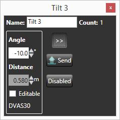
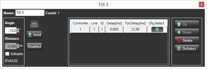
16 Other functions are: Master Function window 's compact view: Function window 's expanded view: Curve Function window 's compact view: Function window 's expanded view: Tilt Function window 's compact view: Function window 's expanded view: 16/28 Rev 2.0
 select/deselect the devices belong group (clicking Select Button) delete Group Eq.")
17 Functions List Window The Functions list window shows a list with all the active functions: This window permits to: change name of function open specific function window (clicking View Button) select/deselect the devices belong group (clicking Select Button) delete Group Eq. (clicking Delete Button) 17/28 Rev 2.0

18 ADVANCED FEATURES Parameter Protection Modality DVA Network allows to switch between 2 protection level: SoundCheck modality: Unprotected Mode; user can edit all parameters in real time. Group Equalization, Volume and delay are changed in Live time; mute, solo and presets are sent to audio devices without confirmation. Concert modality: Protected Mode, using the Settings window user can select one by one which parameter will be protected in this modality. Equalization, delay and Gain can be locked or the Live mode can be disabled, requiring a manual Send on every modification. A Confirmation popup can be set to request a confirmation for Mute and solo. Storing parameters in Device Some DVA Network compatible devices permit to store in their memory the actual Equalizzation/Gain/Delay that users have configured by DVA Network software. The Store all Eq. button trigger a store data procedure to all the connected and Store-enabled devices in the synoptic. For detailed information about recalling stored Eq. please refer to the device s manual. Properties Window The properties window shows all the available properties of the selected devices and allows to change the properties values (e.g. Preset, HPF Filter Preset, etc) simultaneously. If selected devices are not of the same type (e.g. DVA T12 and DVA S30 in the same selection) only mute is displayed. 18/28 Rev 2.0
 can be connected to the PC directly using USB: in this case they are seen by the software as Serial Device and added in the controller list.")
 Check firmware version of the Control Configuration Summary Window Configuration Summary View ( Menu")
19 Controllers Window DVA Network software supports more than one Control device connected at the same time. For example you can connect a Control 2 using USB together with a Control 8 using Ethernet. Standalone devices (e.g. AC26N audio processor) can be connected to the PC directly using USB: in this case they are seen by the software as Serial Device and added in the controller list. The controllers window ( Menu System Controls list ) displays a list of detected Control units: Controllers window is useful to: Edit controller name Check IP and MAC address if the control is connected using Ethernet Check the number of slaves connected on each Control sub-network (line) Check firmware version of the Control Configuration Summary Window Configuration Summary View ( Menu System Summary ) display a list of all connected devices. The Order by functionality allow to order devices by Controller, Group and Line: 19/28 Rev 2.0
. 20/28 Rev 2.")
20 The Columns Setup functionality allow to enable/disable specific columns within some useful informations regarding devices like: The image above show the columns enabled by default Either Delay and Phase parameters take into account all the Delays variations applied through groups and functions into the speakers, and consider preset parameters (e.g. Delay preset in DVA S30). 20/28 Rev 2.0


21 Communication Log Communication Log window (Menu Advanced Communication Log) show a log of each command sent by software to any RDNet device. It is useful in detecting any failure in the Net. Every Command Cmd is identified by an ID number and the column State indicates the outcome of the command. If an error occurs the State field displays TIMEOUT or ERROR and the user can investigate which device generated the error by consulting Controller, Line and Slave fields. Control 2 / Control 8 Firmware Upgrade DVA Network allows you to update Control 2/8 internal firmware. To access this functionality open Menu Advanced Control2/Control8 Firmware Upgrade : In order to proceed a Control 2/8 unit must be connected through an USB port. The default firmware location is C:\Program Files (x86)\dbtechnologies\dva Network\FirmwareUpgrade 21/28 Rev 2.0

22 Settings To access this functionality open Menu Options Settings : Snap to grid: devices placed in synoptic snap to the grid;allow to customize the vertical and horizontal grid steps. Default and optimized value is GridX 80 and GridY 80 Link Objects when overlap: It s a magnetic link that graphically joins devices to each other if they are overlapped. Synchronize Options: enable/disable the reading of some parameters like Preset and Mute at Scan Devices program process Wizard Window Options: enable/disable the opening of wizard window at program startup Live Gain Enabled: Real time Gain update in Concert Mode Live Delay Enabled: Real time Delay update in Concert Mode Live Eq. Enabled: Real time Eq filter update Concert Mode Preset Change Confirm: Enable a confirmation request if preset is modified in Concert Mode SOLO and MUTE Confirm: Enable a confirmation request if MUTE/ SOLO commands are activated in Concert Mode Eq./Gain/Delay Edit Confirm: Enable a confirmation request if Eq./Gain/Delay Edit are edited in Concert Mode Eq./Gain/Delay Edit Enabled: Enable editing of Eq./Gain/Delay in Concert Mode 22/28 Rev 2.0


23 Wizard Window To access this functionality open Menu File Wizard : This window will appear at every program startup. It is a rapid shortcut to some main program's functionalities: New Session: deletes all the synoptic devices and groups displayed and start a new project. The Scan Devices process is executed automatically if a RDNet control is linked to software. Load Session: loads a previously saved project file. Restore Last Session: loads the latest saved project file! The DVA Network save current work session every 5 seconds to perform the restore process whenever necessary 23/28 Rev 2.0

 24/28 Rev 2.")
24 Firmware Upgrade Window To access this functionality open Menu Advance Devices Firmware Upgrade : To upgrade the single device follow these tips: choose the specific device model to upgrade by window's Model combobox (e.g. T8 ) 24/28 Rev 2.0


25 Guidelines will be shown on the window to help the user perform the device upgrade Automatically the latest device's firmware will be selected to perform device upgrade. It will be possible select a different device's firmware to perform device upgrade clicking the specific window's LOAD button Click UPDATE button to continue the device upgrade process. A new window will be shown: Click START UPDATE button to perform device upgrade: Click OK button to close device upgrade process: 25/28 Rev 2.0

26 ETHERNET CONNECTION Control 8 can be connected to DVA Network software through an Ethernet connection. The simplest way to configure the connection requires the usage of an Ethernet hub with both PC and Control 8 connected. Configure control 8 To configure Control8 for the Ethernet connection for the first time it s necessary to connect the control to the PC through a USB cable. Open DVA Network software and make sure that RDNet Control8 firmware is updated to the latest available release. To access this functionality open Menu Options Ethernet Control 8 Config : A window will appear showing the current Ethernet IP Address and ports numbers used by the Control 8. It s important that the Ethernet Subnet (the first three numbers of the IP address) matches the Ethernet router subnet address. For example if the router s address is , Control8 s IP address must be set to X with X from 2 to 255. If your Ethernet router supports DHCP (automatic IP addressing) it is recommended to enable this option in the Ethernet configuration window so that an IP address will be automatically assigned. 26/28 Rev 2.0
: Use the discovery function to start an automatic search of Ethernet available for Control 8 units.")
27 Connection procedure Once Control8 Ethernet connection is properly configured, it s possible to unplug USB and connect PC and Control8 to the Ethernet hub. In DVA Network software open the Ethernet connection window ( Menu System Ethernet Connect ): Use the discovery function to start an automatic search of Ethernet available for Control 8 units. All the detected Controls will be shown in the list, it is possible to assign to each control an arbitrary name and Controller number. To start a connection with a specific controller in the list first select the controller, and then use the Connect button. The Connect All function simply starts a connection with all available controllers. The Disconnect All function simply starts a disconnection with all available controllers connected. 27/28 Rev 2.0

28 October 2014 R&D Dept. db Technologies a brand of A.E.B. Industriale Srl dva_network@dbtechnologies-aeb.com 28/28 Rev 2.0
dbtechnologies REFERENCE MANUAL Document version 2.1
 REFERENCE MANUAL Document version 2.1 RDNET PROTOCOL OVERVIEW... 3 Network description... 3 Connection topology... 3 SOFTWARE BASIC OPERATIONS... 4 Main View elements... 4 Scanning device and Online procedure...
OPERATION MANUAL REV. 0.1
 OPERATION MANUAL REV. 0.1 TABLE OF CONTENTS 1. GENERAL INFORMATION...3 1.1. WELCOME!...4 1.2. SYSTEM REQUIREMENTS*...5 1.3. INSTALLATION...6 2. A CONTROLS OVERLOOK...7 2.1. 2.2. 2.3. 2.4. MAIN MENU BUTTON...9
SOFTWARE INSTRUCTIONS DIGITAL SPEAKER PROCESSOR DP-SP3
 SOFTWARE INSTRUCTIONS DIGITAL SPEAKER PROCESSOR DP-SP3 Thank you for purchasing TOA s Digital Speaker Processor. Please carefully follow the instructions in this manual to ensure long, trouble-free use
minidsp Kit USER MANUAL V1.6 Revision Description Date V1.5 minidsp PCB revision - Rev V1.6 New minidsp PCB revision Rev
 minidsp Kit USER MANUAL V1.6 Revision Description Date V1.5 minidsp PCB revision - Rev1 31-05-2010 V1.6 New minidsp PCB revision Rev2 16-12-2010 V1.7 Jumper for RevA & B 26-03-2012 Table of content 1 System
User Manual. Lupisoft
 EKIO User Manual Lupisoft TABLE OF CONTENTS Introduction... 3 Software Installation... 3 Setting up your system... 3 Overview of the EKIO interface... 5 Menu... 6 Config Selection... 7 Inputs/Outputs Tab...
DIGITAL AUDIO PROCESSOR
 SOFTWARE SETUP MANUAL DIGITAL AUDIO PROCESSOR DP-K1 (Version 1.05) This book supports the following software versions. Firmware: Version 2.00 or later DP-K1 setting software: Version 2.00 or later [Instruction
This manual has been created to help end-users step through the various pages and functions of EAWPilot and access all of its powerful features.
 EAWPilot Introduction To EAWPilot EAWPilot is an extremely fast and intuitive software created to aid the users of the UX8800, UX3600 + NT products in evaluating, building, storing and recalling complex
minidsp Balanced 2x4
 minidsp Balanced 2x4 USER MANUAL V1.0 Revision Description Date V1.0 User manual Initial version 24-12-2010 Table of content 1 System setup...3 2 minidsp Basics...4 2.1 What is a minidsp?...4 2.2 minidsp
PowerShare Editor User's Guide. Version 2.0
 PowerShare Editor User's Guide Version 2.0 08.01.2017 Table of Contents Table of Contents 2 Introduction 5 Install PowerShare Editor 6 Minimum System Requirements 6 Installation Steps 6 Windows Display
Fohhn Audio Soft. User Manual. One software to control all processes
 Fohhn Audio Soft One software to control all processes User Manual Please read this manual carefully before using the software and keep it for future reference. Contents 1. Welcome... 5 2. Introduction...
minidsp Kit USER MANUAL V1.5 Revision Description Date V1.0 User manual Initial version
 minidsp Kit USER MANUAL V1.5 Revision Description Date V1.0 User manual Initial version 15-12-2009 V1.1 Layout re-organization Modification on synchronization process Added section about PEQ 10-02-2010
Controlling the JBL Professional DSC260 System Controller Using SIA-Smaart Pro
 Controlling the JBL Professional DSC260 System Controller Using SIA-Smaart Pro SIA Software Company, Inc. an EAW Company The SIA-Smaart Pro Real-Time module can control crossover and delay functions on
Note: Unit is set at the factory for 120V operation. Be sure to change the fuse (2A rating) before switching to 230V operation.
 before switching to 230V operation.") Note: Unit is set at the factory for 120V operation. Be sure to change the fuse (2A rating) before switching to 230V operation. (2) FCC Statement 1. This device complies with Part 15 of the FCC Rules.
Note: Unit is set at the factory for 120V operation. Be sure to change the fuse (2A rating) before switching to 230V operation. (2) FCC Statement 1. This device complies with Part 15 of the FCC Rules.
DSP Audio Processor. Operation Manual. Control Software and Device Front Panel Operation. Unika DSP-1000 Unika DSP-1001 Unika DSP- 428
 Operation Manual Control Software and Device Front Panel Operation Unika DSP-1000 Unika DSP-1001 Unika DSP- 428 Index Tools... 3 Unit Window:Main Panel... 5 Main Setup Screen Functions... 8 Input Channel
PowerShare Editor User's Guide. Version 1.0
 PowerShare Editor User's Guide Version 1.0 07.22.2016 Table of Contents Table of Contents 2 Introduction 4 Install PowerShare Editor 4 Minimum System Requirements 4 Installation Steps 4 Windows Display
Multi Amplifier Remote Control (MARC) Software QUICK START GUIDE 1.0.0
 Software QUICK START GUIDE 1.0.0") Multi Amplifier Remote Control (MARC) Software QUICK START GUIDE 1.0.0 Welcome to Dynacord s Multi Amplifier Remote Control (MARC) Quick Start Guide. We want you to get the most from your Dynacord amplifiers
Multi Amplifier Remote Control (MARC) Software QUICK START GUIDE 1.0.0 Welcome to Dynacord s Multi Amplifier Remote Control (MARC) Quick Start Guide. We want you to get the most from your Dynacord amplifiers
minidsp Kit USER MANUAL V1.6
 minidsp Kit USER MANUAL V1.6 Important note: This user manual only applies to board of minidsp Rev2, shipped starting from early December 2010. If your board does not look like the picture below, please
nanodigi 2x8 USER MANUAL
 nanodigi 2x8 USER MANUAL B Revision Description Date V1.0 Initial revision 28-06-2012 V1.1 Updated section 07-05-2013 V1.2 Update of matrix mixer section 24-03-2016 www.minidsp.com P 1 Contents 1 Product
DSP Software Manual for Tact Millennium MkIII
 DSP Software Manual for Tact Millennium MkIII Manual Rev. 1.1 based on DSP software v1.21 and MkIII firmware release 30. Introduction: The DSP software suite is the key to programming the presets of the
minidsp Kit USER MANUAL V1.6
 minidsp Kit USER MANUAL V1.6 Important note: This user manual only applies to board of minidsp Rev2, shipped starting from early December 2010. If your board does not look like the picture below, please
minidsp Balanced Kit
 minidsp Balanced Kit USER MANUAL V1.4 Revision Description Date V1.0 User manual Initial version 24-09-2010 V1.1 Sensitivity Jumper clarifications 24-09-2010 V1.2 Updated various sections 23-12-2010 V1.3
Bose ControlSpace Designer Software. User Guide
 Bose ControlSpace Designer Software User Guide 2005 Bose Corporation. No part of this work may be reproduced, modified, distributed or otherwise used without prior written permission. Contents Introduction
Contents. Introduction 3. Controls and functions 8. Setup 10. Reference 39. Panel Operation 12
 Reference Manual EN Contents Introduction 3 Features...3 Manuals for PX amplifier...3 Usage examples...4 Use with two full-range speakers...4 Use with a full-range speaker and subwoofer...4 Use with a
DPA-240A Digital Speaker Processor
 DPA-240A Digital Speaker Processor User Manual Described below are the functions of the front panel control buttons and encoders for the DPA- 240A. Getting Started As soon as the DPA-240A is turned ON
For additional information, please consult the Read-Me and Help documentation or contact Electro-Voice or Dynacord technical support.
 Quick Start Guide Hello, and welcome to IRIS-Net software. We want you to get the most from your IRIS-Net projects and encourage you to explore the additional Read-Me and Help documentation provided with
User Manual Digital & Analog Pre-Amplifier DA3
 WWW.MOBRIDGE.US CONTACT US PHONE +61 3 946 997 / INQUIRIES sales@mobridge.com.au User Manual Digital & Analog Pre-Amplifier DA3 Contents WWW.MOBRIDGE.US Figure Diagrams FIG 01 DA3 Connected 06 FIG 02 DA3
USER S MANUAL Musicson MDCS
 2017 USER S MANUAL Musicson MDCS Control and Monitoring Software 3.8.20 Release Contests 1.- Star and Daisy-Chain Network Typologies... Page 4 2.- Musicson Dsp Software Installation... Page 4 3.- Musicson
Waves GTR3 ToolRack Manual
 Waves GTR3 ToolRack Manual Waves GTR ToolRack Manual 1 TABLE OF CONTENTS CHAPTER 1 INTRODUCTION...3 1.1 WELCOME...3 1.2 PRODUCT OVERVIEW...3 1.3 COMPONENTS...4 1.4 AUTOMATION...4 MIDI Automation...4 CHAPTER
Digital Speaker Management System
 Digital Speaker Management System DSM-26LAN Order No. 25.5760 DSM-48LAN Order No. 25.5770 INSTRUCTION MANUAL ELECTRONICS FOR SPECIALISTS ELECTRONICS FOR SPECIALISTS ELECTRONICS FOR SPECIALISTS ELECTRONICS
ControlSpace Designer software 5.0.2
 BOSE Professional ControlSpace Designer software 5.0.2 March 2, 2018 Revision: 1.0 General This release includes an update to ControlSpace Designer to fix an issue where duplicating a PowerMatch in Project
Note: Unit is set at the factory for 120V operation. Be sure to change the fuse. (2A rating) before switching to 230V operation.
 before switching to 230V operation.") Note: Unit is set at the factory for 120V operation. Be sure to change the fuse (2A rating) before switching to 230V operation. (2) FCC Statement 1. This device complies with Part 15 of the FCC Rules.
Note: Unit is set at the factory for 120V operation. Be sure to change the fuse (2A rating) before switching to 230V operation. (2) FCC Statement 1. This device complies with Part 15 of the FCC Rules.
4 x 8 DSP DIGITAL SIGNAL PROCESSOR FOR HOME AND CAR AUDIO. Model: DSP-408 User Manual
 4 x 8 DSP DIGITAL SIGNAL PROCESSOR FOR HOME AND CAR AUDIO Model: DSP-408 User Manual Table of Contents 2. Table of Contents 3. Product Overview/General Safety Instructions/Box Contents 4. DSP Features
minidsp 8x8 USER MANUAL
 minidsp 8x8 USER MANUAL Revision Description Date V1.0 Initial revision 01-07-2011 V1.1 Updated section on input/output jumpers 30-09-2011 V1.2 IR remote & Firmware upgrade instructions 26-10-2011 www.minidsp.com
Operating Manual. Genelec Loudspeaker Manager GLM 2.0 System
 Operating Manual Genelec Loudspeaker Manager GLM 2.0 System 1 Genelec SAM GLM 2.0 System Operating Manual page 2 of 39 Table of Contents Introduction... 4 Glossary... 5 System Components... 6 SAM Monitors...
FCC Statement. 1. This device complies with Part 15 of the FCC Rules. Operation is subject to the following two conditions:
 (2) FCC Statement 1. This device complies with Part 15 of the FCC Rules. Operation is subject to the following two conditions: (1) This device may not cause harmful interference. (2) This device must accept
minidsp 4x10 Hd USER MANUAL
 minidsp 4x10 Hd USER MANUAL Revision Description Date V1.0 Initial revision 28-06-2012 V1.1 Updated section on volume control 03-08-2012 www.minidsp.com P 1 Contents 1 Product Introduction... 3 2 System
Signal Interface Processor ADVANCED MANUAL PRELIMINARY
 www..eu PRELIMINARY Signal Interface Processor ADVANCED MANUAL is a part of elettromedia - 62018 Potenza Picena (MC) Italy - www.elettromedia.it Product Description Bit One is a signal digital processor
Operation manual. DeviceControl NomadLink Network Control and Monitoring Software. Rev Item no. OM-DC
 Operation manual DeviceControl NomadLink Network Control and Monitoring Software Rev. 2.0.0 Item no. OM-DC 1 contents 1 CONTENTS...2 2 DeviceControl InTroduCtion...4 2.1 Overview...4 2.2 New features in
XD360 Operation Manual
 XD360 Operation Manual The XD360 Extreme Drive is designed to provide flexibility, sonic excellence and intuitive controls for loudspeaker and EQ management. The XD software with USB PC connectivity offers
2X4 HD COMPACT 2-IN 4-OUT HIGH-RESOLUTION AUDIO PROCESSOR 2X4 HD KIT 2-IN 4-OUT HIGH- User Manual PROCESSOR CIRCUIT BOARD RESOLUTION AUDIO
 2X4 HD COMPACT 2-IN 4-OUT HIGH-RESOLUTION AUDIO PROCESSOR 2X4 HD KIT 2-IN 4-OUT HIGH- RESOLUTION AUDIO PROCESSOR CIRCUIT BOARD User Manual minidsp Ltd, Hong Kong / www.minidsp.com / Features and specifications
Installation & User manual for the mobridge M1000-M-DA series of Pre-Amplifiers
 MOBRIDGE M1000-M-DA SERIES INSTALL NOTES MOBRIDGE M1000-M-DA BMW INSTALLATION V1.0 Installation & User manual for the mobridge M1000-M-DA series of Pre-Amplifiers PAGE 1 WELCOME!... 3 DISCLAIMER... 4 BMW
USER S MANUAL. Dual Channel 15 Band EQ USB. 19" DIGITAL (482mm) DS-EQ215 PARAMETER OUT EQUALIZER ESCAPE
 DS-EQ215 PARAMETER OUT EQUALIZER ESCAPE") DS-EQ215 USER S MANUAL IN PARAMETER DS-EQ215 OUT EQUALIZER ESCAPE Dual Channel 15 Band EQ 19" DIGITAL (482mm) USB Contents Introduction...1 Safety Instructions... 2 Getting Started with Front Panel Controls...
DS-EQ215 USER S MANUAL IN PARAMETER DS-EQ215 OUT EQUALIZER ESCAPE Dual Channel 15 Band EQ 19" DIGITAL (482mm) USB Contents Introduction...1 Safety Instructions... 2 Getting Started with Front Panel Controls...
AC ELWA -E Electrical Photovoltaic-Excess Hot-Water-Device. Operation Manual
 AC ELWA -E Electrical Photovoltaic-Excess Hot-Water-Device Operation Manual Content 1. Assembly... 2 2. Controls and displays... 2 3. Operation displays... 2 4. Factory presets... 2 5. Placing into operation
Installation Guide & Users Manual
 Installation Guide & Users Manual 1. PRODUCT DESCRIPTION & WARNINGS DSP-88R is a digital signal processor essential to maximize the acoustic performance of your car audio sys-tem. It consists of a 32-bit
Tracktion Shortcut Keys
 Tracktion Shortcut Keys General Flip between edit/project screens Go to project screen Go to edit screen Go to settings screen escape, ctrl + tab F1 F3 F2 Show colour-scheme editor window Save the current
RC-SV Configuration Guide (Rev 4)
") Kramer Electronics, Ltd. RC-SV Configuration Guide (Rev 4) Software Version 2.1.2.69 Intended for Kramer Technical Personnel or external System Integrators. To check that you have the latest version, go
Kramer Electronics, Ltd. RC-SV Configuration Guide (Rev 4) Software Version 2.1.2.69 Intended for Kramer Technical Personnel or external System Integrators. To check that you have the latest version, go
PWR-ICE125 PWR-ICE250. User Manual DSP-CONTROLLED PLATE AMPLIFIER
 PWR-ICE125 PWR-ICE250 DSP-CONTROLLED PLATE AMPLIFIER User Manual minidsp Ltd, Hong Kong / www.minidsp.com / Features and specifications subject to change without prior notice 1 Revision history Revision
PC/IP Manual. Advanced Installers Package
 PC/IP Manual Advanced Installers Package CONTENTS 1 Introduction 2 Installation Software installation and registration 3 Initial system set-up Monitor task assignment 4 Main display screen features Setup
K-framework 2 User Guide English
 K-framework 2 User Guide English System requirements Operating System: Windows XP / Vista / 7 / 8 / 10 CPU: Intel Pentium Dual Core Memory: 2 GB 1 TABLE of CONTENTS 1. software installation and settings...
BlueBridge Designer II. User Guide
 1 AtlasIED.com Table of Contents Introduction... 4 Glossary... 6 Installation... 8 Installation Notes... 9 Connecting to the Network...10 Initial Device Connectivity... 12 Launch the BlueBridge Designer
Installation manual for 42HFL5007D/10 47HFL5007D/10
 Philips Hospitality TV Installation manual for 42HFL5007D/10 47HFL5007D/10 Version 1.1 Contents 1. Requirements before starting the installation... 2 2. Find out the state of the TV... 3 3. Re-install
DSI-2 OWNER S MANUAL
 DSI-2 OWNER S MANUAL INTRODUCTION Thank the you for purchasing the DD Audio DSI-2. The DSI-2 is a feature rich audio signal processor that will allow you to precisely tune the acoustics of a vehicle's
OpenDRC-DI USER MANUAL.
 OpenDRC-DI USER MANUAL Manual revision Description Date V1.0 Initial revision 18-02-2012 V1.1 Firmware upgrade information 18-04-2012 V1.2 DSP upgrade step by step 17-07-2012 www.minidsp.com P 1 Contents
Installation Manual for 22HFL4373D/10 26HFL4373D/10 32HFL4373D/10 42HFL4373D/10
 Philips Hospitality TV Installation Manual for 22HFL4373D/10 26HFL4373D/10 32HFL4373D/10 42HFL4373D/10 Version 1.0 Contents 1. Requirements before starting the installation... 2 2. Find out the state of
AUDIO MANAGEMENT CONTROLLER (AMC) MANUAL
 MANUAL") AUDIO MANAGEMENT CONTROLLER (AMC) MANUAL Page 1 Description The Blue Sky Audio Management Controller (AMC) is an 8-channel audio DSP platform with both 24-bit digital and analog I/O. Each channel of the
AUDIO MANAGEMENT CONTROLLER (AMC) MANUAL Page 1 Description The Blue Sky Audio Management Controller (AMC) is an 8-channel audio DSP platform with both 24-bit digital and analog I/O. Each channel of the
DSPController. PC Remote control for MA series D Software v2.4 Firmware v1.1.x.x
 DSPController PC Remote control for MA series D Software v2.4 Firmware v1.1.x.x Pol.Ind.Norte-Perpinyà,25 08226 TERRASSA (Barcelona-SPAIN) info@master-audio.com www.master-audio.com User s Manual February
User Manual Sonic Wave I
 User Manual Sonic Wave I 3D Sound Processor Version 3.0.1 Table of Contents SAFETY INFORMATION 5 INTRODUCTION 6 THE SOFTWARE 7 1. SONIC WAVE I TOPOLOGY 8 HD OPTION 9 2. SONIC WAVE I HARDWARE 10 CONNECTIONS
Installation (Mac) Contents. Introduction. Installation (Windows) System Requirements
 Contents. Introduction. Installation (Windows) System Requirements") USER GUIDE V1.0 2004 Focusrite Audio Engineering Ltd. Disclaimer: FOCUSRITE, the FF Logo, LIQUID CHANNEL, LIQUID TECHNOLOGY, LIQUIDCONTROL, EVERYONE NEEDS LIQUID, and the LIQUID CHANNEL Logo are trademarks
USER GUIDE V1.0 2004 Focusrite Audio Engineering Ltd. Disclaimer: FOCUSRITE, the FF Logo, LIQUID CHANNEL, LIQUID TECHNOLOGY, LIQUIDCONTROL, EVERYONE NEEDS LIQUID, and the LIQUID CHANNEL Logo are trademarks
OPERATION MANUAL. MV-410HS Layout Editor. Version higher. Command
 OPERATION MANUAL MV-410HS Layout Editor Version 3.0 - higher Command Command Table of Contents 1. Setup... 1 1-1. Overview... 1 1-2. System Requirements... 1 1-3. Operation Flow... 1 1-4. Installing MV-410HS
OpenDRC-AN USER MANUAL.
 OpenDRC-AN USER MANUAL Manual revision Description Date V1.0 Initial revision 13-07-2012 www.minidsp.com P 1 Contents 1 Product Introduction... 3 2 System Connectivity... 5 2.1 Connectivity... 5 2.2 Typical
DSLP48. Loudspeaker Management System User Manual
 DSLP48 Loudspeaker Management System User Manual Table of Contents 1.0 Introduction... 3 2.0 Features... 4 3.0 Front Panel Functions... 5 4.0 Rear Panel Functions... 6 5.0 Powering Up the Device... 7 6.0
DirectOut Technologies
 DirectOut Technologies D.O.TEC ANDIAMO Remote Software Guide Version 1.2 DirectOut Technologies page 2 of 69 D.O.TEC ANDIAMO Remote - Version 1.2 2013 DirectOut GmbH DirectOut Technologies Copyright Note
DCM-Lx Series Operation Manual
 DCM-Lx Series Operation Manual DCM3800Lx DCM2004Lx Concert audio has to be uncompromising, reliable and efficient. Carvin power amps have made their mark serving top artists and concert venues for decades.
K-framework 2 User Guide English
 K-framework 2 User Guide English System requirements Operating System: Windows XP / Vista / 7 / 8 CPU: Intel Pentium Dual Core Memory: 2 GB 1 TABLE of CONTENTS 1. software installation and set up... 4
Previous LS9 Firmware version information
 Previous LS9 Firmware version information Firmware V1.34 Improvement Improved detection accuracy of internal battery voltage. ltage field of the MISC SETUP screen. Fixed Fixed a problem in which the Post
Operating Manual. Genelec Loudspeaker Manager GLM 2.0 System
 Operating Manual Genelec Loudspeaker Manager GLM 2.0 System Genelec Loudspeaker Manager (GLM) 2.0 - System Operating Manual page 2 of 55 Table of Contents Introduction... 4 Glossary... 5 System Components...
AC ELWA -E Electrical Photovoltaic-Excess Hot-Water-Device. Operation Manual
 AC ELWA -E Electrical Photovoltaic-Excess Hot-Water-Device Operation Manual Content 1. Assembly... 2 2. Controls and displays... 2 3. Operation displays... 2 4. Factory presets... 3 5. Placing into operation
miniambio 2.0 USER MANUAL V1.0 Revision Description Date V1.0 User manual Initial version P 1 of 12
 miniambio 2.0 USER MANUAL V1.0 Revision Description Date V1.0 User manual Initial version 10-10-2010 P 1 of 12 1 miniambio Basics To better understand the benefits of Ambiophonics, you first need to understand
CDD-LIVE! Firmware Update
 We are delighted to announce a firmware update for the CDD range which adds a new feature enabling the speakers to be configured for use on a network with a Static IP address as an alternative to the default
RC-SV Configuration Guide Revision 3
 Kramer Electronics, Ltd. RC-SV Configuration Guide Revision 3 Software Version 2.1.2.32 Intended for Kramer Technical Personnel or external System Integrators. To check that you have the latest version,
Lake Controller v6.3.0 Release notes
 Lake Controller v6.3.0 Release Notes 1 (57) Lab.gruppen AB Lake Controller v6.3.0 Release notes Important information about features, compability and known issues Lake Controller v6.3.0 Release Notes 2
Application Note IC-2-RS485
 Application Note IC-2-RS485 Revision 1.0 July 2010 Serial Control of Iconyx RHAON Series Arrays Abstract: The Iconyx RHAON models have an RS485 connection for serial control via third-party controllers
SigmaStudio User Manual
 SigmaStudio User Manual CONTENT Page 1. Using SigmaStudio Preset Templates... 2 1.1. Finding and Downloading the SigmaStudio Project Templates... 2 1.2. Arranging the Workspace... 2 1.2.1. Status Bars...
Patch A patch is a configuration of Slice EQ that gives it a certain sound. Whenever you pull a slider or turn a knob you modify the current patch.
 OPERATOR'S MANUAL 1 Table of contents Glossary... 3 System requirements... 4 Overview... 5 User interface... 5 Operating the controls... 6 Working with patches... 7 Building your sound... 8 Edit tool...
PRONET Loudspeaker Control Software USER MANUAL
 PRONET Loudspeaker Control Software USER MANUAL RELEASE 2.3 1 Summary 1 Introduction... 5 1.1 Welcome to PRONET: the PRONET philosophy... 5 1.1.1 What's New?... 5 1.2 Contacts... 5 1.3 Credits... 5 2 Installation...
Download the new firmware from the X32 product page onto the root level of a USB Flash drive (FAT formatted).
.") X32 FIRMWARE UPDATE UPDATE INSTRUCTIONS X32 Firmware updates are issued periodically to add new features, fix reported software bugs and improve product performance. Updates are designed to be user-installed
X32 FIRMWARE UPDATE UPDATE INSTRUCTIONS X32 Firmware updates are issued periodically to add new features, fix reported software bugs and improve product performance. Updates are designed to be user-installed
Inout DA Console Manual
 Inout DA Console Manual Version 2.0 INOUT AUDIO COMMUNICATION SYSTEMS Via Nobel, 10 30020 Noventa di Piave Venezia ITALY Tel. +39 0421 571411 Fax +39 0421 571480 web:www.inout-digital.com email:info@inout-digital.com
SwitchMan Quartet. Preliminary User s Guide. Dec. 08, 2000 Firmware revisions: Main v1.3, Remote v1.1
 SwitchMan Quartet Preliminary User s Guide Dec. 08, 2000 Firmware revisions: Main v1.3, Remote v1.1 Table of Contents SwitchMan Quartet... 1 Table of Contents... 2 1. Product Brief... 3 Product changes
DPA AMT. 8 I n - 8 O ut Digital Matrix Mixer with Automixer USB DIGITAL. 482mm 19"
 DPA- 8 8 0 AMT 8 I n - 8 O ut Digital Matrix Mixer with Automixer 482mm 19" DIGITAL USB DPA880AMT Digital 8x8 Conference System Matrix with Automixer Function and Priority Ducker User Manual For the microphone
ALLCONTROL RELEASE NOTES
 ALLCONTROL RELEASE NOTES In this document pending requests, changes, bugfxes, and known issues related to our AllControl application software and the frmware for our DSP hardware products are listed. For
SRC MEM USER S MANUAL. rev. 1.0 a
 SRC MEM USER S MANUAL rev. 1.0 a USER S MANUAL bit Nove / Index 1. PRODUCT DESCRIPTION / PRECAUTIONS...3 2. PACKAGE CONTENTS...3 3. BIT NOVE and DRC INSTALLATION... 4 4. CONNECTION PANEL DESCRIPTION...5
M9 - NDAS. User Manual. External Storage Enclosure for 3.5 IDE Hard Drives. (English) v1.4
 v1.4") M9 - NDAS External Storage Enclosure for 3.5 IDE Hard Drives User Manual (English) v1.4 EN Table of Contents CHAPTER 1 - INTRODUCTION - 1 - CHAPTER 4 - NDAS SETUP - 7 - ICON KEY - 1 - DRIVER INSTALLATION
M9 - NDAS External Storage Enclosure for 3.5 IDE Hard Drives User Manual (English) v1.4 EN Table of Contents CHAPTER 1 - INTRODUCTION - 1 - CHAPTER 4 - NDAS SETUP - 7 - ICON KEY - 1 - DRIVER INSTALLATION
User Guide. AX32 SPQ card and Pro Mon 3 option
 User Guide AX32 SPQ card and Pro Mon 3 option IMPORTANT SAFETY INSTRUCTIONS READ AND KEEP THESE INSTRUCTIONS WARNING when using electric products, basic precautions should be followed, including the following:
DSM26 DIGITAL SPEAKER MANAGEMENT SYSTEM. Order ref: UK User Manual. Features
 DSM26 DIGITAL SPEAKER MANAGEMENT SYSTEM Order ref: 170.665UK User Manual Features 2 inputs, 6 outputs, fully balanced Independent parametric EQs Delay and Compressor/Limiter/Gate functions All inputs/outputs
StepPolyArp Unit. Step Polyphonic Arpeggiator / Sequencer App & Audio Unit MIDI effect for ios
 StepPolyArp Unit Step Polyphonic Arpeggiator / Sequencer App & Audio Unit MIDI effect for ios Presentation... 1 Application setup... 2 MIDI connections between ios applications... 2 MIDI over WiFi on macos...
APPLICATION NOTE. Delta Series, DPA Series, APA Series. Grouping Architecture
 APPLICATION NOTE Delta Series, DPA Series, APA Series Grouping Architecture Grouping Architecture Page 2 Introduction AudioCore is XTA s mature remote control software application, that runs under Windows
POWERSOFT THE CONFIGURATOR Instructions for the system configuration and synoptic setup
 POWERSOFT THE CONFIGURATOR Instructions for the system configuration and synoptic setup Version 09/09 Rel. 2.1.0.4 INDEX 1 THE CONFIGURATOR... 3 1.1 What the configurator is... 4 1.2 The configurator functions...
Filter Hose. User Guide v 2.0
 Filter Hose User Guide v 2.0 Contents FEATURE 2 COMPATIBILITY AND KNOWN ISSUES 3 APPLICATION NOTES 3 NAVIGATION 5 UNDERSTANDING FILTER HOSE USER INTERFACE 5 THE FIVE STEP CONTROL PANEL 6 USER DEFINED FILTER
SoundWare DSP Software User's Manual Version 1.0.0
 SoundWare DSP Software User's Manual Version 1.0.0 September 2014 Contents Brief 4 Getting Started (HW & SW) 5 Load a Preset From Device 7 Load All Presets From PC 8 Save All presets to PC 9 Load a Preset
TENVIS Technology Co., Ltd. User Manual. For H.264 Cameras. Version 1.0.0
 TENVIS Technology Co., Ltd User Manual For H.264 Cameras Version 1.0.0 Catalogue Basic Operation... 3 Hardware Installation... 3 Search Camera... 3 For Internet Explorer... 6 Playback Record Files... 9
2016 PRODUCT CATALOG More than 45 countries, on 5 continents. Present in the world and making a difference!
 206 PRODUCT CATALOG More than 45 countries, on 5 continents. Present in the world and making a difference! BRAZIL 204/205 BEST AMPLIFIER www.stetsomaudio.com /grupostetsom /Stetsom USA STETSOM BRAZIL Presidente
Digitakt OS 1.07 Release Information
 Digitakt OS 1.07 Release Information Elektron Music Machines March 9, 2018 How to upgrade: Upgrading from within the OS Select SYSTEM in the SETTINGS menu, and then select OS UPGRADE. Send the SysEx firmware
THETA DIGITAL. master quickstart guide
 THETA DIGITAL master quickstart guide Page 2 Step by Step Guide to Naming Inputs The Casablanca III HD can show up to four letters for input names on the front panel VFD (Vacuum Fluorescent Display). 2.
01V96 Editor. Owner s Manual. Special Notices. Contents. Yamaha Pro Audio Global Site
 01V96 Editor Owner s Manual Special Notices The software and this owner s manual are the exclusive copyrights of Yamaha Corporation. Copying of the software or reproduction of this manual in whole or in
R Remote Version 4.5 User s Guide
 R Remote Version 4.5 User s Guide Thank you for choosing a Yamaha product. This user s guide explains setup, firmware update and use of "R Remote," a Windows/Mac application that lets you make parameter
Release Date Description V Release for the second time. New features: V First release Change History 1. Test Tool is a
 Rev: V3.1.0 Doc number: NS110000297 SmartLCT LED Display Configuration Software User Manual Release Date Description V3.1.0 2017-05-25 Release for the second time. New features: V3.0.0 2017-01-20 First
CAUTION RISK OF ELECTRIC SHOCK DO NOT OPEN
 4 In - 8 Out Speaker Management System Introduction DPA480 is the flagship of Marani s digital speaker management systems. Designed for maximum versatility, it provides all the processing and control necessary
CRAGG RAILCHARGER Instruction Manual for 10DTC-12V 20DTC-12V 30DTC-24V 40DTC-12V 60DTC-12V
 CRAGG RAILCHARGER for 10DTC-12V 20DTC-12V 30DTC-24V 40DTC-12V 60DTC-12V Contents 1 Warnings, Cautions, and Notes... 1 2 Description... 2 3 Features... 2 3.1 STANDARD FEATURES... 2 3.2 CHARGER REGULATION...
i-series DSPControl SOFTWARE MADE IN GERMANY
 i-series DSPControl SOFTWARE MADE IN GERMANY i-series DSPControl SOFTWARE CONTENTS User manual for the DSPControl software TDA30XDSPCGBD Revision D, 2014-10-07 Please visit our website for the latest version
Pleiades - NDAS. User Manual. External Storage Enclosure for 3.5 IDE Hard Drives. v1.2
 Pleiades - NDAS External Storage Enclosure for 3.5 IDE Hard Drives User Manual v1.2 EN Table of Contents CHAPTER 1 - INTRODUCTION - 1 - CHAPTER 4 - NDAS SETUP - 8 - ICON KEY - 1 - DRIVER INSTALLATION ON