Modicon Momentum automation platform. Catalog
|
|
|
- Laurence Carroll
- 6 years ago
- Views:
Transcription
1 Catalog 0
2
3
4 A full range of catalogs for Catalog 00 Detection Automation Automation Operator dialog Motion and Drives & Global Detection Electronic and electromechanical sensors MKTED00EN Photo-electric sensors Proximity sensors Capacitive proximity sensors Ultrasonic sensors Limit switches Pressure switches Rotary encoders Radio frequency identification Machine cabling accessories & Modicon Quantum Catalog 00 MKTED00EN-US Safety PLCs Safety CPUs Unity Concept and ProWORX software & Modicon Premium Catalog 00 MKTED00EN-US Unity processors PL processors Communication software & Modicon M0 Catalog 00 DIAED000EN-US PLCs Discrete, analog I/O and application-specific solutions Communication & Catalog 00 MKTED00EN-US & Twido programmable controller and TwidoSuite software DIAED000EN Controller base Discrete, analog I/O Communication & Automation functions, relays, interfaces and power supplies MKTED00EN Smart relays Timing relays Measurement & control relays Analog interfaces Counters Plug-in relays Interfaces for discrete signals Power supplies & transformers Software PLCs and safety controllers programming software & Control and signalling components MKTED00EN Control and signalling units Control stations & enclosures Cam switches Beacons and indicator banks Pendant control stations Controllers Emergency stops Foot switches & Magelis Human/Machine Interfaces Catalog 00 MKTED00EN-US Operator interface terminals Industrial PCs HMI and SCADA PC-based software Software Vijeo Designer Operator terminal software & Lexium Servo Drives motion control Catalog 00/00 DIAED000EN-US Motion controllers Servo drives and Servo motors Stepper motors and drives Integrated drives Modicon Premium motion control modules & Soft starters and variable speed drives MKTED0EN Soft starters and variable speed drives Software Software for drives Motor control programming software Some products shown in this catalog are not available in every country. Check individual country s web site or Sales Office for product availability. See our web site:

5 ..... Automation & Control functions Motor control Machine safety Interfaces and I/O Power supplies Systems & architectures & Motor starter solutions Control and protection components MKTED00EN Contactors Circuit-breakers, carriers Thermal relays Combinations, motor controllers Mounting solutions Motor starter mounting kits This catalog contains Automation and Control function products relating to machines Safety & Preventa Machine Safety Products Catalog 00 MKTED00EN-US Safety PLCs Safety controllers Safety monitors Safety solutions on AS-Interface cabling system Safety switches Safety light curtains Safety mats Emergency stops Control stations Enabling switches Foot switches Beacons & indicator banks Switch disconnectors Thermal-magnetic motor circuit breakers Enclosed D.O.L. starters & Terminal blocks MKTED00EN Terminal blocks Cable ends & Modicon STB IP 0 distributed inputs/outputs Catalog 00 MKTED00EN-US Modules for automation station Network interfaces Power distribution Digital I/O, analogs and application-specific Software STB configuration software & Phaseo power supplies and transformers DIAED00EN Switch mode power supplies Filtered rectified power supplies Transformers This catalog contains Automation and Control function products relating to Communication & Machine & Installations with industrial communication MKTED00EN Preferred implementations Ethernet TCP/IP, the universal communication standard CANopen for machines and installations AS-Interface, simple and ASI-Safe Products Human-Machine interface Controllers and PLCs Field devices Infrastructure and wiring Gateways Software and tools Collaborative Automation Partner Program & Partners Software XPSMFWIN configuration software XPSMCWIN configuration software
6 Contents b Introduction Discrete I/O bases Selection guide... b Introduction, description... b Specifications b References b Dimensions, mounting... 0 b Wiring diagrams... 0 Analog I/O bases Selection guide... b Introduction, description... b Specifications b References b Dimensions, mounting... b Wiring diagrams... Specialty module I/O bases Selection guide... b Introduction, description... 0 b Specifications b References b Wiring diagrams... Communication adapters Selection guide... b Ethernet TCP/IP network communication adapters b Modbus Plus network communication adapters... 0 b FIPIO bus communication adapters... b In t e rbu s bus communication adapters b Profibus DP bus communication adapter... 0
7 M/ME processor adapters and option adapters Processor adapters selection guide b M/ME processor adapters v Introduction v Description... v Specifications... v References... Option adapters selection guide b Option adapters v Introduction v Description... v Specifications... v References... Ethernet network cabling system b Infrastructure b ConneXium connection components... b ConneXium hub... 0 b ConneXium transceiver b ConneXium switches... Programming software (for M/ME processor adapters) b Concept IEC programming software v Introduction v Functions... v References... b ProWORX for Ladder Logic programming software v Introduction v References... Additional products and services b Optional conformal coating for agressive environments v Introduction v References... 0 b Enhanced grouding system v Introduction v References... 0 b User documentation... 0 b Automation product certifications... 0 b Community regulations b Product reference index... 0 Advantys, Altistart, Altivar, Concept, ConneXium, FactoryCast, FIPIO, FIPway, Lexium, Magelis, M0, Modbus, Modbus Plus, Modicon, Modsoft, Momentum, OSItrack, Phaseo, PowerSuite, Premium, Preventa, ProWORX, Quantum, Schneider Electric, Telefast, TeSys, Transparent Ready, TSX Micro, Twido, TwidoSoft, TwidoSuite, Unity, Unity Pro, Vijeo Designer, Vijeo Look X-Way are trademarks or registered trademarks of Schneider Electric. Other trademarks used herein are the property of their respective owners. 0
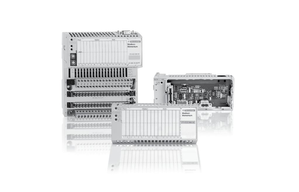
8 Introduction A modular concept with four easy pieces The I/O system is comprised of fundamental components that easily snap together in various combinations to form a versatile, distributed I/O system. The four components are: I/O base Communication adapter Processor adapter Option adapter I/O base Communication adapter Option adapter () Processor adapter () Modicon Momentum communication adapters The design of the Modicon Momentum separates the communications from the I/O base, thus creating a truly open I/O system that can be easily adapted to any fieldbus network. When a Modicon Momentum I/O is coupled with a communication adapter, the two form a remote I/O drop that connects directly to virtually any standard fieldbus I/O network. Together, Modicon Momentum I/O supports different types of control systems, including: personal computers, distributed control systems, programmable controllers and Modicon Momentum processors. Modbus Plus communication adapter () The processor adapters are only compatible with Concept or ProWORX software. 0
9 Introduction (continued) I/O bases A specialized Modicon Momentum I/O base supports the rest of the control system. The communication adapter, processor adapter and option adapter all snap onto the I/O base. A selection of I/O base modules are available, including analog I/O, discrete I/O, multi-function analog and bi-directional discrete bases. In addition, Modicon Momentum I/O bases offer simple plug-in terminal strips, as well as standard mm DIN rail or panel mounting, for ease of maintenance and installation. Communication adapter I/O base Modicon Momentum processors adapters and option adapters () When local distributed intelligence is required at the point of control, Modicon Momentum has the answer. The Modicon Momentum M processor adapter is a full fledged PLC containing a CPU, RAM and Flash memory. It is based on the popular Modicon family of PLCs (i.e., directly compatible with Quantum, Compact and PLCs), and snaps onto the Modicon Momentum I/O base, just like the communication adapter. The option adapter provides the processor adapter with additional networking capabilities, a time-of-day clock, and a battery back-up. The option adapter also snaps onto the I/O base. In the figure below,the processor adapter is stacked on top. Option adapter Processor adapter () I/O base Optional conformal coating If your control system needs to operate in a corrosive environment, selected Modicon Momentum modules can be ordered with a conformal coating applied to components of the product. Conformal coating will extend product life and enhance its environmental and performance capabilities. See pages 00 and 0. Enhanced grounding system Due to new In t e rbu s standards for electrical noise immunity, a number of Modicon Momentum products have been updated to include an enhanced grounding system. This system is required to meet the revised electrical noise immunity standard (ability to pass a. kv electrical fast transient burst test). See page 0 for a list of Modicon Momentum products that currently have been updated to include the new grounding system. () The processor adapters are only compatible with the Concept or ProWORX software. 0

10 Selection guide Discrete I/O bases Product type Input modules for direct current Input modules for alternating current Type of signal True high Operating voltage and Input voltage Vdc 0 Vac 0 Vac Current consumption max. 0 ma max. ma Input type IEC Type + IEC Type IEC Type + Output voltage Output type Number of points x In x In x In Potential isolation Point to point None None Group to group None 0 Vac Field to adapter 00 Vac 0 Vac Current capacity Per output Per group Per module Response time OFF-ON. ms 0 0 Hz. 0 Hz ON-OFF. ms 0 Hz. 0 Hz Protection against short circuit and overload Fault reporting Detected output fault Detected I/O error Blown Type of module 0 ADI ADI ADI ADI Pages

11 Output modules for direct current Output modules for alternating current Relay output module True high Vdc 0 Vac 0 Vac 0 to 0 Vdc max. 0 ma max. ma max. ma 0 Vac 0VDC Vdc 0 Vac 0 Vac 0 to 0 Vac to 0 Vdc Solid state switch Triac Relay from C x out x out x out x out x out x out out (isolated) None None 0 Vac for mn None None 0 Vac for mn 00 Vac 0 Vac 0 Vac for mn 0. A 0. A A 0. A A 0. A A A A A A A A A A A A A A A 0 C 0 C < 0. ms max. / x /f 0 ms < 0. ms max. / x /f 0 ms Electronically safeguarded per group LED/Out LED/ Out None to adapter to adapter None LED 0 ADO ADO ADO ADO ADO ADO ADO 0 0 0
12 Selection guide (continued) Discrete I/O bases Product type I/O modules for direct current Type of signal True high True low True high Input voltage Vdc Operating voltage Vdc Current consumption max. 0 ma max. 0 ma + sensor current 0 Input type IEC Type + Output voltage Output type Vdc Solid state switch Number of points x In, x Out x In, x Out Potential isolation Point to point None Group to group None Field to adapter 00 Vac Current capacity Per output 0. A A Per group A A Per module A A Response time OFF-ON. ms In, < ms Out 0 ms in, < ms Out. ms In, < ms Out ON-OFF. ms In, < ms Out 0 ms in, < ms Out. ms In, < ms Out Protection against short circuit and overload Electrically safeguarded outputs Electrically safeguarded outputs and electronically safeguarded sensor supply group Fault reporting Detected output fault LED/Out Detected I/O error to adapter Blown Type of module 0 ADM ADM 0 0 ADM 0 0 ADM 0 0 Pages 0
13 I/O modules for direct current I/O modules for direct and alternating current True high Vdc,, Vdc Vdc 0 Vac Vdc,, Vdc Vdc 0 Vac max. 0 ma 00 Vdc 0 Vdc Vdc max. 0 ma max. 0 ma IEC Type +, monitored IEC Type + IEC Type Vdc,, Vdc 0 Vac or 0 Vdc / Vdc (0 ADM 0 only) Solid state switch Relay (normally open) Triac x In, x Out and x Out 0 Vac x In, x Out x 0 In, x Out x 0 In, x Out None None None 0 Vac None None None None 0 Vac None 00 Vac 0 Vdc 00 Vac 00 Vac 0 Vac 0. A 0. A A ohmic load 0. A A group, A group A ohmic load A A 0 C, 0 C A ohmic load A. ms In, < ms Out. ms In, <. ms Out. ms In, < 0 ms Out max / x /f. ms In, < ms Out. ms In, <. ms Out. ms In, < 0 ms Out max / x /f Electronically safeguarded outputs Electrically safeguarded outputs None Varistor in parallel with each contact internal per group (not against overload) LED/In, LED/Out LED/Out None None to adapter to adapter None None LED/ 0 ADM ADM ADM 0 0 / 0 ADM 0 0 ARM ADM 0 0
14 Introduction, description Discrete I/O bases Introduction products are modular in design. Communication adapters and Processor adapters are designed to work as functional modules when they are snapped onto a Modicon Momentum I/O base. This I/O base requires that some type of Modicon Momentum adapter be attached before it can be functional. I/O bases fit into compact standard housings that can be mounted on a DIN rail or on panels in a cabinet. They read information from field sensing devices and control discrete and analog field actuating devices. Terminal blocks and bus bars are available for use with the bases so that these bases can be used to support -, -, and -wire field devices. I/O field devices and the power supply to the module are connected via three -pin terminal blocks and an optional -, -, or -row busbar. The terminal connectors are electrically connected to the module, while the optional busbars are not. Busbars provide a common connection for the field devices and serve as protective distribution connectors. Depending on the I/O base and the type and number of field devices connected to it, a -, -, or -row busbar may be used. Terminal blocks and busbars are ordered separately, and are not shipped with the Modicon Momentum I/O bases. They are available in either screw-in or spring-clip versions. Description 0 ADp discrete I/O base units feature the following on the front panel: Internal interface connector for the communication module or processor module Locking and ground contact for the communication module or processor module LED status indicators (the number of indicators will depend on the number of channels) Up to three connectors for the removable terminal blocks (Modbus dependent). Grounding screw Slot for the power strip Two screw holes for panel mounting Protective cover Connectors to be ordered separately: b removable screw or spring terminals 0 XTS 00p 00 b to -row screw or spring bus bar 0 XTS 00p 0 0 Specifications: pages to References: page Dimensions, mounting: page 0 Wiring diagrams: pages 0 to
15 Specifications Discrete I/O bases Specifications for discrete input bases Type of input base unit 0 ADI ADI ADI ADI 0 0 Number of inputs x x x Input voltage V DC 0 AC 0 AC Operating voltage V DC AC (@ Hz) AC (@ Hz) Internal current ma 0 (@ Vdc) (@ 0 Vac) (@ 0 Vac) Input voltage range V - 0 DC 0 AC AC ON voltage V + 0 DC AC minimum AC minimum OFF voltage V - + DC 0 AC maximum 0 AC maximum Input current ON ma. minimum 0.0 minimum OFF ma. maximum.0 maximum Input resistance Hz Type of signal True High Response time On-off maximum 0 0 Hz Off-on maximum ms. 0 0 Hz Potential isolation Input to input None None Group to group V None 0 AC Field to communication interface V 00 AC 0 AC Power dissipation W typical, maximum Agency approvals UL, e, CSA, FM Class I, Div. II. typical,. maximum UL, e, CSA UL, e, CSA, FM Class I, Div. II UL, e, CSA 0 References: page Dimensions, mounting: page 0 Wiring diagrams: pages 0 to
16 Specifications (continued) Discrete I/O bases Specifications for discrete output bases Type of output base unit 0 ADO ADO ADO 0 0 Number of outputs x x x Type of output Solid state switch Relay form C Output voltage V DC 0 0 AC, 0 DC Operating voltage V DC 0 0 AC Internal current ma 0 0 Vac Current Point maximum A Group A Module 0 0 C Min. output current ma 0 Leakage current ma Vdc < 0 Vac Surge current A for ms 0 for 0 ms On StateVoltage drop V < A < 0 Vdc Protection (short-circuits, overloads) Outputs electronically protected Via external ma fast-blow Response time On-off maximum ms < 0. 0 Hz Off-on maximum ms < 0. 0 Hz Potential Isolation Output to output V None 0 AC for minute Output group to output group V None 0 AC for minute Field to communication interface V 00 AC 0 AC for minute Power dissipation W. typical. maximum Agency approvals UL, e, CSA, FM Class I, Div. II.0 typical. maximum UL, e, CSA. UL, e, CSA, FM Class I, Div. II Type of output base unit 0 ADO ADO ADO ADO 0 0 Number of outputs x x x x Type of output Triac Output voltage V 0 AC 0 AC Operating voltage V 0 AC (00 for 0 s, 00 for cycle) 0 AC (00 for 0 s, 00 for cycle) Internal current ma Current Point maximum A Group A Module A Min. output current ma 0 0 Leakage current 0 0 Vac Surge current A Point: ( cycle), 0 ( cycles), ( cycles) On StateVoltage drop V <. A <. 0. A <. A <. 0. A 0 Protection (short-circuits, overloads) Via internal A slow-blow per group Response time On-off maximum ms / x /f (= 0, of one line cycle) Off-on maximum ms / x /f (= 0, of one line cycle) Potential Isolation Output to output None Output group to output group None Field to communication interface V 0 AC Power dissipation W.0 typical. maximum Agency approvals UL, e, CSA, FM Class I, Div. II Description: page References: page Dimensions, mounting: page 0 Wiring diagrams: pages 0 to
17 Specifications (continued) Discrete I/O bases Specifications for discrete I/O bases Type of base unit 0 ADM ADM 0 0 ADM 0 0 ADM 0 0 Number of inputs x x Number of outputs x x and x Operating voltage Vdc Internal current ma Vdc Vdc Inputs Voltage Vdc Type of signal True high True low True high Voltage at Vdc Voltage at 0 Vdc Input current ma. min. at state ( ma at c V),. max. at state 0 Input voltage range Vdc Input resistance kw Response time Off to on ms In, < Out On to off ms In, < Out Fault sensing Broken wire detection Outputs Voltage Vdc, 0 max. Type Solid state switch Type of signal True high True low True high Current capacity A 0. per point per group per module 0. per point per group per group per module Leakage current ma Vdc Vdc Peak current A for ms On state voltage drop Vdc < 0. A Detected error indication Output overload for at least one output to communication adapter Output overload for at least one output to communication adapter Response time Off to On ms < 0. On to Off ms < 0. Potential isolation Input to input None Output to output group None Input to output group None Field to communication interface V 00 AC Power dissipation Typical W.0. Maximum W Agency approvals UL, e, CSA UL, e, CSA, FM Class I, Div. II 0 Description: page References: page Dimensions, mounting: page 0 Wiring diagrams: pages 0 to
18 Specifications (continued) Discrete I/O bases Specifications for discrete I/O bases Type of base unit 0 ADM ADM 0 0 Number of points Inputs x x Outputs x x Operating voltage Vdc,, (0 0) Internal current ma Vdc (plus current for sensors) Vdc Vdc Inputs Voltage Vdc,, Type of signal True high Voltage at Vdc Vdc Vdc > Vdc Voltage at 0 Vdc - + Vdc Vdc < Vdc Input current ma. min. at state ( ma at c V),. max. at state Vdc Input voltage range Vdc V Input resistance kw Response time Off to On ms. In, < Out. In, <. Out On to Off ms. In, < Out. In, <. Out Fault sensing Outputs Voltage Vdc, 0 max.,,, 0 max. Type Type of signal Solid state switch True high Current capacity A per point per group per module 0. per point per 0 C per 0 C Leakage current ma Vdc 0 Vdc Peak current A. for ms for ms On state voltage drop Vdc 0. A Detected error indication Output overload for at least one output or short-circuit or overload on one of the encoder supply groups, to communication adapter Response time ms < 0. Off to On, < 0. On to Off Potential isolation Input to input None Output to output group None Input to output group V None 0 DC Field to communication interface Vrms 00 AC 0 DC Output overload for at least one output to communication adapter Power dissipation Typical W..0 + (0. x nb of input points) + (0. x nb of output points) Maximum W 0.0 Agency approvals UL, e, CSA UL, e, CSA, FM Class I, Div. II 0 Description: page References: page Dimensions, mounting: page 0 Wiring diagrams: pages 0 to
19 Specifications (continued) Discrete I/O bases Specifications for discrete I/O bases Type of base unit 0 ADM 0 0 / 0 ADM 0 Number of points Inputs x 0 Outputs x 0 ARM 0 0 Operating voltage V DC 0 AC (... Hz) Internal current ma Vdc minimum load current Inputs Voltage V...0 AC 0... DC Signal type True High On voltage minimum Vdc Off voltage maximum Vdc Input current ma. minimum On,. maximum Off Input voltage range Vdc Input resistance kw Response time ms. Off to On,. On to Off Outputs Voltage V...0 AC, 0... DC / Vdc (0 ADM 0 only) Type Relay normally open Current capacity Vdc A > 0.00 (new contacts), ohmic load A maximum, inductive load A maximum (LR y 0 ms) Current capacity Vdc A Ohmic load 0. A maximum (switching current y. A), inductive load 0. A maximum (LR y 0 ms) Current capacity Vac A A maximum (switching current y. A) cosj =, A maximum cosj = 0. Leakage current ma 0 Vac Detected error indication None Response time ms 0 Hz Off to On, 0 Hz On to Off A per point, A per group, A per module Max. number of switching circuits > 0 x 0 (mechanical), > x 0 (inductive load with external protection circuit) Protection against short circuit and overload None Varistor in parallel with each contact Potential isolation Input to Input None Output group to output Group V rms None 0 AC Input to output group V rms None 0 AC Field to communication interface V rms 00 AC Fusing Internal None External operating voltage ma fast-blow A fast-blow External input voltage max. A fast-blow None External output voltage According to the supply of the connected actuators not to exceed A slow-blow/group None Power dissipation Typical W. Maximum W. Agency approvals UL, e, CSA UL, e, CSA, FM Class I, Div. II 0 Description: page References: page Dimensions, mounting: page 0 Wiring diagrams: pages 0 to
20 Specifications (continued) Discrete I/O bases Specifications for discrete I/O bases Type of base unit 0 ADM 0 Number of points Inputs x 0 Outputs x Operating voltage Vac 0 (... Hz) Internal current ma 0 (@ 0 Vac) Inputs Voltage Vac 0 Signal type True high On voltage minimum Vac Off voltage maximum Vac 0 Input current ma.0 minimum at state,. maximum at state 0 Input voltage range Vac... Input resistance kw Response time ms Maximum / x /f Off to On, maximum / x /f On to Off Outputs Voltage Vac 0 (@ Hz) Type Triac Current capacity 0. A per point maximum, 0 ma per point minimum, A per group, A per module Leakage current ma <. (@ 0 Vac) Signal type True High On state voltage drop Vac <. (@ 0. A) Detected error indication None Response time ms / x /f maximum from state 0 to state, / x /f maximum from state to state 0 Maximum switching cycles Potential Isolation Input to input None Output group to output group None Input to output group None Field to communication interface Vrms 0 AC Power dissipation Typical W Maximum W 000/hr for 0. A inductive load Protection Internal s A x. slow-blow s Agency approvals UL, e, CSA 0 Description: page References: page Dimensions, mounting: page 0 Wiring diagrams: pages 0 to
21 References Discrete I/O bases 0 ADI pp0 p0 0 ADO pp0 p0 0 ADM pp0 pp 0 XTS XTS XTS XTS 00 0 CER 00 0 BSM 0 00 Discrete input bases Type of current Modularity (no. of points) Conformity EC - Reference Weight kg DC V ( x ) Type 0 ADI ( x ) Type 0 ADI AC 0 V ( x ) Type 0 ADI V ( x ) Type 0 ADI Discrete output bases Type of current Output voltage Modularity (no. of points) DC solid state protected DC/AC relay form C AC triac protected, per group Discrete I/O bases Type of output current Input voltage DC solid state Current per output Reference Weight kg V ( x ) 0. A 0 ADO ( x ) 0. A 0 ADO Vdc isolated A 0 ADO Vac 0 V ( x ) A 0 ADO ( x ) 0. A 0 ADO V ( x ) A 0 ADO ( x ) 0. A 0 ADO Vdc Type + Output voltage Vdc protected Modularity Reference Weight Input Outputs, current kg I ( x ) O ( x ) 0. A 0 ADM I, fast ( x ) O ( x ) 0. A 0 ADM I ( x ) O ( x ) 0. A 0 ADM I, wiring O ( x and x 0 ADM check ( x ) ) 0. A I ( x ) O ( x ) A 0 ADM DC relay 0 Vdc 0 Vdc I ( x ) O ( x ) 0. A 0 ADM 0 0 AC or DC relay Vdc Type + AC triac 00 0 Vac Type /0 Vac 0/ Vdc 0 I ( x 0) O ( x ) A 0 ADM 0 0 () ARM 0 () ARM 0 0 () Vac 0 I ( x 0) O ( x ) 0. A protected by 0 ADM Accessories Description Composition Type of connection Reference Weight kg Terminal blocks for I/O base connection Set of connectors row Screw 0 XTS Spring 0 XTS Bus Bar rows Screw 0 XTS 00 0 Spring 0 XTS 00 0 rows Screw 0 XTS 00 0 Spring 0 XTS 00 0 row Screw 0 XTS 00 0 Spring 0 XTS 00 0 Cable grounding rail Used to connect CER 00 the cable shielding High vibration Kit containing sets of clips 0 XTS 0 00 environment clips Dummy base unit Used to prewire the I/O base units 0 BDM Requires screw or spring connection terminals Discrete input simulator channels, Vdc 0 BSM 0 00 Replacement parts Description Use Reference Weight kg Sheets of labels 0 front labels for modules 0 XTS Cable coding For screw or spring connection terminals 0 XCP part kit () Operating voltage Vdc. () Output voltage Vdc. () Operating voltage 0 Vac. 0 Description: page Specifications: pages to Wiring diagrams: pages 0 to
22 Dimensions, mounting, wiring diagrams Discrete I/O bases Dimensions, mounting 0 ADp, rail or panel mounting, () 0, 0 () () holes for M screws, for panel mounting () Equipment or enclosure Wiring diagrams for discrete input bases 0 ADI ADI 0 00 Example of external wiring of, and -wire sensors Example of external wiring of and -wire sensors 0 M L+ ma fast-blow V Return 0 M L+ ma fast-blow V V Return L+ L+L+ A max. fast-blow Option M PE A max. fast-blow Option L+ M M L+ L+ IN + PE -wire sensor IN + -wire sensor -wire sensor IN + IN + M M M M A max. fast-blow -wire sensor -wire sensor Group of channels Group of channels Internal wiring Internal wiring -wire sensor 0 ADI ADI 0 0 Example of external wiring of and -wire sensors Example of external wiring of and -wire sensors 0 V 0 N L 00 ma 0 V slow-blow Return Return 0 N L 00 ma slowblow 0 V Return 0 V Return L L L L NN NN -wire sensor IN + - PE -wire sensor -wire sensor IN + - PE -wire sensor 0 -wire sensor -wire sensor Group of channels Group of channels Internal wiring Internal wiring Description: page Specifications: pages to 0
23 Wiring diagrams (continued) Discrete I/O bases Wiring diagrams for discrete output bases 0 ADO ADO 0 00 Example of external wiring of and -wire actuators Example of external wiring of and -wire actuators Option 0L+ L+ M L+ PE V A max. V fast-blow Return A max. fast-blow ma fast-blow 0 L+L+ Option 0 M L+ M M M PE V ma V fast-blow Return A max. fast-blow A max. fast-blow + Out PE PE PE -wire actuator -wire actuator Out PE -wire actuator + -wire actuator Out PE -wire actuator Group of channels Group of channels Internal wiring Internal wiring 0 ADO 0 0 Example of external wiring 0 M L NO 0/0 VCA L Fast-blow N ma NF 0 Option PE Output Output Output Group of channels Internal wiring 0 Description: page Specifications: pages to References: page Dimensions, mounting: page 0
24 Wiring diagrams (continued) Discrete I/O bases Wiring diagrams for discrete output bases 0 ADO 0 0/ADO ADO 0 0/ADO 0 0 Example of external wiring of and -wire actuator Example of external wiring of and -wire actuators Fuse ( A slow-blow) Fuse ( A slow-blow) Option 0 N L Out - PE -wire actuator L N -wire actuator N L PE 0 V Return 0 V Return Group of channels Group of channels 0 A fast-blo w 00 ma fast-blow Fuse ( A slow-blow) Fuse ( A slow-blow) 0NL Option Out - PE -wire actuator L N -wire actuator N L PE 0 V Return 0 V Return 0 A fast-blow 00 ma fast-blow Internal wiring Internal wiring 0 Description: page Specifications: pages to References: page Dimensions, mounting: page 0
25 Wiring diagrams (continued) Discrete I/O bases Wiring diagrams for discrete I/O bases 0 ADM 0 0/ADM 0 /ADM 0 Example of external wiring of a -wire sensor/actuator 0 M L+ 0 LL+ ma fast-blow A max. fast-blow V V Return Example of external wiring of a -wire actuator with wiring check 0 M L+ 0 LL+ ma fast-blow A max. fast-blow V V Return Option M M L+ A max. fast-blow A max. fast-blow Option M M PE A max. fast-blow I O -wire sensor -wire actuator Out PE -wire actuator Group of channels Group of channels Internal wiring Internal wiring Example of external wiring of a -wire sensor activated by an output 0 M L+ ma fast-blow V V Return Example of external wiring of a -wire sensor/-wire actuator 0 M L+ ma fast-blow V V Return 0 LL+ A max. fast-blow 0 LL+ A max. fast-blow Option M M PE A max. fast-blow Option M M L+ M A max. fast-blow A max. fast-blow IN + PE PE -wire sensor -wire sensor IN + PE -wire actuator -wire sensor Group of channels Group of channels Internal wiring Internal wiring 0 Description: page Specifications: pages to References: page Dimensions, mounting: page 0
26 Wiring diagrams (continued) Discrete I/O bases Wiring diagrams for discrete I/O bases 0 ADM ADM 0 0 Example of external wiring of -wire sensor/actuator Example of external wiring of and -wire sensors/-wire actuator 0 M L+ 00 ma fast-blow V V Return 0 M L+ A max. fast-blow V V Return Option I L+ L+ k M M L+ A max. fast-blow A max. fast-blow A max. fast-blow 0 L+ Option L+ L+ L+ L+L+ M M M PE A max. slow-blow A max. slow-blow k (connected directly to sensor) O -wire actuator IN + PE -wire sensor + -wire actuator -wire sensor Group of channels Group of channels Internal wiring Internal wiring 0 ADM 0 0 (continued) Example of external wiring of -wire actuator with wiring check Special external wiring, the output activates the sensor 0 M L+ A max. 0 L+ L+ slow-blow V A max. V fast-blow Return 0 M L+ 0 L+L+ A max. fast-blow A max. slow-blow V V Return L+ Option L+ L+ L+ M M PE M A max. slow-blow L+ Option L+ L+ L+ M M PE M A max. slow-blow Out PE -wire actuator IN + PE -wire sensor Group of channels Group of channels Internal wiring Internal wiring 0 Description: page Specifications: pages to References: page Dimensions, mounting: page 0
27 Wiring diagrams (continued) Discrete I/O bases Wiring diagrams for discrete I/O bases 0 ADM ADM 0 0 / 0 ADM 0 Example of external wiring of: v -wire sensor v -wire actuator v -wire actuator with wiring check v -wire sensor actived by output Example of external wiring of or sensor/-wire/actuator I I0 I 0 M-L+ O O0 O () 0 0 V 0 0 Return 0 L+ M M L+M L+ ma fast-blow V Return L N 0 M-L+ max. 0 A () P M 0M P M-L+ ma () max. A () Option IN L - PE () L+ 0 L+L M N N L - PE () N N PE A max. fast-blow A max. slow-blow A max. slow-blow In + -wire sensor PE + -wire actuator In PE -wire actuator Sensor actived by output -wire sensor Group of channels Group of channels -wire actuator Internal wiring Internal wiring () Fast-blow : c V: 0 ma, c V: ma, c V: 00 ma. () Fast-blow. () For -wire sensor () For -wire actuator 0 ARM ADM 0 Example of external wiring of -wire sensor/-wire actuator Example of external wiring of -wire sensor/ and -wire actuators N L L+ M PE L+L N PE N N PE a 0 V A max. fast-blow Return A max. slow-blow N Fuse (, A slow-blow) 0 NC N N N Fuse a V (, A slow-blow) Return a 0 V N N L N N L L ma fast-blow A max. slow-blow A max. N fast-blow PE Return a V Return IN + PE IN PE -wire sensor L N PE IN Out N PE L N -wire sensor -wire actuator -wire sensor -wire actuator -wire actuator Group of channels Group of channels Internal wiring Internal wiring 0 Description: page Specifications: pages to References: page Dimensions, mounting: page 0
28 Selection guide Analog I/O bases Applications Vdc analog input bases Operating voltage Vdc Measurement range Inputs ± V, ± 0 V, ± 0 ma - V, -0 ma Inputs ± V, ± 0 V, -0 ma Inputs ± mv, ± 00 mv, Temperature probe Pt 00, Pt 000, Ni 00, Ni 000 Thermocouple B, E, J, K, N, R, S, T Modularity Input channels differential inputs single-ended inputs differential inputs Output channels Discrete I/O Resolution bits + sign bipolar bits unipolar bits + sign bits + sign Update time. +. x no. of declared channels (ms) +. x no. of declared channels (ms 00 ms Potential isolation Between channels 00 Vdc, min None 00 Vdc Base and ground 00 Vdc, min 00 Vdc, min 00 Vdc, min Channels and ground 00 Vac, min 0 Vac, min 00 Vac Protection Polarity inversion Number in words In words in words in words in Out words out words out words out Fail states Type of communicating module 0 AAI AAI AAI 0 0 Pages 0
29 Vdc analog output bases Vdc mixed I/O bases (analog/discrete) Vdc Vdc Vdc Outputs ± 0 V, 0-0 ma Outputs ± 0 V, -0 ma Inputs ± V, ± 0 V, ± 0 ma - V, -0 ma Outputs ± 0 V, 0-0 ma Inputs 0 0 V Outputs 0 0 V Inputs V Outputs V differential inputs inputs with common point outputs outputs outputs with common point inputs Vdc outputs Vdc/0. A inputs Vdc outputs Vdc/ A inputs Vdc outputs Vdc/0. A bits + sign Inputs: bits (dep. on range) Outputs: bits Inputs: bits Outputs: bits ms Inputs: 0 ms Outputs: ms None None 00 Vdc, min 00 Vac, min 00 Vac, min 00 Vac, min Polarity inversion Short-circuits and overloads (for discrete outputs) Inputs: 0. ms (for inputs) Outputs:. ms (for inputs) words in words in words in words out words out words out words out Hold, reset to zero, reset to full scale Hold or reset to zero 0 AAO AAO 00 0 AMM AMM ANR ANR 0 0
 b Low level (± mv, ± 00 mv) b Thermocouples (B, E, J,...) b Temperature probes (Ni..., Pt.")
30 Introduction, description Analog I/O bases Introduction analog input bases enable acquisition of various analog values encountered in industrial applications, including: b Standard high level (± V, ±0 V, - V, -0 ma, ± 0 ma) b Low level (± mv, ± 00 mv) b Thermocouples (B, E, J,...) b Temperature probes (Ni..., Pt...) Analog output bases are used to control analog field devices such as: speed drives and proportional control valves. The current or the voltage is proportional to the digital value defined by the user program. The outputs can be configured so that when the program stops, the outputs either reset to zero or hold the last value received. This feature is useful during debugging because, if the outputs are set to Hold, the operation of the analog field devices is not disturbed every time the program stops. Designed to cover a wide range of applications, Modicon Momentum I/O bases offer the following functions in addition to A/D or D/A conversion: b Choice of input/output ranges (voltage, current, thermocouple, temperature probes) b Selection of number of channels used b Cold junction compensation for thermocouple modules b Broken wire detection (0 AAI 00 00, 0 AAI 0 00 and 0 AAI 0 0 models) Description 0 App analog I/O base units feature the following on the front panel: Internal interface connector for the communication module or processor module Locking and ground contact for the communication module or processor module LED status indicators (the number of indicators will depend on the number of channels) Two connectors for the removable terminal blocks Grounding screw Slot for the power strip Two screw holes for panel mounting Protective cover Connectors to be ordered separately: b removable screw or spring terminal blocks 0 XTS 00p 00 b to -row screw or spring bus bar 0 XTS 00p 0 0
31 Specifications Analog I/O bases Specifications for analog input bases Type of base units 0 AAI Number of inputs x differential imputs LEDs Format of data Ready (green) Full bits signed ( s complement) Protection Base and actuators Polarity inversion Ranges ± 0 Vdc ± Vdc 0 ma ± 0 ma Vdc Input impedance kw >.000 > >.000 Maximum variation at C % Maximum variation at 0 C % Resolution bits + sign bipolar bits unipolar Conversion times ms ms max. for input channels (. ms per input channel +. ms) Error indication None Isolation Channel to channel Vdc ± 00 for minute Field to ground Vdc 00 for minute Communication adapter to Vac 00 for minute ground Common mode rejection Channel to ground 0 Hz or 00 Vdc Crosstalk between channels db u 0 External power requirement Nominal Vdc Limit values Vdc 0. to. Current ma Vdc EMC for industrial environment Immunity IEC surge on auxiliary power supply kv Emissions EN 00- Approvals UL, CSA, e 0 References : pages and Dimensions : page Wiring diagrams : pages and
32 Specifications (continued) Analog I/O bases Specifications for analog input bases Type of base units 0 AAI AAI 0 0 Number of inputs x single-ended input x differential inputs Format of data Full bits signed ( s complement) Protection Base and actuators Polarity inversion Error indication Ranges ± 0 V ± V 0 ma ± mv ± 00 mv Input impedance kw > 00 > 00 < 0.0 > 0000 > 0000 Maximum variation at C 0. % FS 0. % FS 0. % FS ± µv ± µv Maximum variation at 0 C 0. % FS 0. % FS 0. % FS ± µv ± µv Temperature drift (0 C) 0 PE / C 0 PE / C 0 PE / C PE (Full scale) 0 V V ma Resolution bits + sign bits + sign bits bits + sign Filtering Low pass with cut-off frequency 0 khz Current source Pt00 ma 0. Ni00 ma 0. Pt000 ma 0. Ni000 ma 0. Update time ms +. x n n = number of declared channels Error indication None Potential isolation Channel to channel Vdc None 00 Base power supply and ground Vdc 00 for minute 00 for minute Channels to ground Vac 0 for minute 00 for minute Base power V ± 0 (voltage or current output) ± 0 (voltage or current output) Common mode Channel to ground V ± 00 DC, 0 AC Common mode Voltage between channels None V 00 DC, AC single phase or -phase or 0 AC single phase Common mode rejection Channel to ground 0 Vac at Hz or 00 Vdc db DC, db AC 0 Hz, db AC 0 Hz Between channels 0 db DC, 0 db AC 0 Hz, 0 db AC 0 Hz Serial mode rejection db AC 0 Hz, db AC 0 Hz 00 Input protection Polarity inversion Operating voltage Vdc Internal current ma Vdc Power dissipation Typical W.. Maximum W.. Fusing Internal A slow-blow A slow-blow External 00 ma fast-blow 00 ma fast-blow Agency approvals UL, e, CSA, FM Class I, Div. II 0 References : pages and 0 Dimensions : page Wiring diagrams : pages and
33 Specifications (continued) Analog I/O bases Specifications for analog output bases Type of base units 0 AAO AAO 00 Number of outputs x Format of data Full bits signed ( s complement) Protection Base and actuators Polarity inversion Ranges ± 0 V 0 0 ma ± 0 V 0 ma Load impedance kw minimum 0. maximum minimum 0. maximum Capacitive load µf < Maximum variation at C % 0. PE 0. PE 0. PE 0. PE Maximum variation at 0 C % 0. PE 0. PE 0. PE 0. PE Temperature drift (0 C) 0 PE / C 0 PE / C 0 PE / C 0 PE / C Resolution bits + sign Update time ms < Full scale Fail State 0 V in the range of ± 0V ma in the range of 0 0 ma Hold, reset to zero, reset to full scale Potential isolation Channel to channel None Base power supply and ground Vdc 00 for minute Channels to ground Vac 00 for minute Outprotections Short-circuits in the voltage circuits, open in current polarity inversion Base power V ± 0 (voltage or current output) Common mode rejection Vac Hz or 0 DC channel to ground Operating voltage Vdc Internal current Base ma Vdc Actuators ma Vdc Power dissipation Typical W. Maximum W. Internal fusing A, slow-blow Agency approvals UL, e, CSA 0 References : pages and Dimensions : page Wiring diagrams : pages and
34 Specifications (continued) Analog I/O bases Specifications for discrete and analog I/O bases Type of base unit 0 AMM AMM 00 0 Number of inputs and outputs x differential inputs x discrete inputs x analog outputs x discrete outputs Operating voltage Vdc Internal current ma 00 typical (at Vdc), 0 maximum (at Vdc) Differential inputs for 0 AMM 00 00/ maximum (at Vdc) Conversion time 0 ms for all channels Conversion tolerance ± 0 V ± V V ± 0 ma 0 ma C % C % Resolution bits bits bits bits bits Conversion consistency % ± 0.0 ± 0.0 ± 0.0 ± 0.0 ± 0.0 Common mode voltage Input voltage starting at Ag ± V Common mode suppression db > 0 Overvoltage Voltage ranges V ± 0 solid state if voltage is V ± 0 dynamic max. 00 ms ± 0 solid state if voltage is V ± 0 dynamic max. 00 ms Overvoltage current ranges ma > Input resistance W M 0 Fail state Hold or reset to zero Discrete inputs Voltage Vdc typical, 0 maximum typical Signal Type True high On Voltage Vdc Off Voltage Vdc Input current ma. minimum at state ( ma at operating voltage),. maximum at state 0 Input resistance kw. Response time ms. from 0 to state. from to state 0 Analog outputs Resolution bits for single-phase measuring range 0 0 ma, bits for -phase measuring range ± 0 V Conversion time ms for all channels Conversion maximum variation C max. ± 0. % of upper measuring range value 0 C max. ± 0.0 % of upper measuring range value Output load u kw for voltage output, y 00 W for current output Discrete outputs Voltage Vdc typical, 0 maximum Type Semiconductor Signal Type True high Current capacity per channel, per group, per module Leakage current ma Vdc Vdc On State Voltage drop Vdc < A < 0. A Response time Off to On ms < 0. On to Off ms < 0. Output protection The outputs are protected against overload and short-circuit-circuiting Output indicator red LED per On output in the event of an overload or short-circuit-circuiting Error message Message I/O error on bus adapter if module is defective Max. Switching cycles 000/hr (inductive load A), 00/s (resistive load A), /s (filament load. W) Potential isolation Discrete input and output None Analog input to output None Analog input and output and to Vac 00 for minute operating voltage Operating voltage and inputs and outputs from ground Vac 00 for minute Power dissipation Typical W.0 Maximum W.0 0 Agency approvals UL, e, CSA, FM Class I, Div. II UL, e, CSA References : pages and Dimensions : page Wiring diagrams : pages and
35 Specifications (continued) Analog I/O bases Specifications for discrete and analog I/O bases Type of base unit 0 ANR ANR 0 Number of inputs and outputs x analog inputs x discrete inputs x analog outputs x discrete outputs Operating voltage Vdc, range...0 Internal current ma Vdc Analog inputs Resolution bit Input range Vdc Input type Single-ended Conversion time 0. ms maximum for input channels Conversion tolerance 0. C for 0-0 Vdc inputs Max input signal Vdc for voltage input Max temperature drift Vdc 0 inputs Input resistance MW > for voltage inputs Discrete inputs Voltage Vdc Configuration groups of inputs Signal Type True high Minimum on voltage Vdc > Maximum off voltage Vdc < Input current Minimum On ma Maximum Off ma Input voltage Range Vdc Surge Vdc peak for 0 ms Response time Off to On ms., On to Off ms. Analog outputs Resolution bit Output range Vdc Conversion time ms.0 for four channels Conversion tolerance max % of upper measuring range C Output load > kw Vdc Fail state Hold or reset to zero Discrete outputs Voltage Vdc 0-0 operating, 0 for ms maximum Type Solid State Switch Signal type True high Current capacity A 0. per point, per group, per module Leakage current ma 0 Vdc Surge current A. for ms On state voltage drop Vdc < 0. A current Response time Off to On ms. On to Off ms.0 Output protection The Outputs are protected against overload and short-circuiting Output indicator LED per point Potential isolation Discrete input to output None Analog input to output None Analog input and output to Vac 00 for minute. operating voltage Operating voltage and inputs and outputs from ground Vac 00 for minute Power dissipation Typical W.0 Maximum W.0 Agency approvals UL, e, CSA 0 References : pages and Dimensions : page Wiring diagrams : pages and
36 References Analog I/O bases 0 AAI pp0 p0 0 AAO pp 00 Analog input bases Type of inputs Number of channels Ranges Reference Weight kg bits + sign single-ended ± V, ± 0 V, -0 ma 0 AAI bits + sign, differential Pt 00, Pt 000, NI 00 thermocouples B, E, J, K, N, R, S, T, differential ± V, ± 0 V, -V ± 0 ma, -0 ma Analog output bases Type of outputs Number of channels 0 AAI AAI Ranges Reference Weight kg bits + sign ± 0 V, 0-0 ma 0 AAO ± 0 V, -0 ma 0 AAO Discrete and analog I/O bases Type Ranges Reference Weight kg Inputs Outputs Inputs Outputs differential analog analogs bits + sign bits discretes discretes 0. A ± V, ± 0 V - V ± 0 ma -0 ma 0-0 ma ± 0 V Vdc Vdc 0 AMM AAM differential analog analogs bits + sign bits ± V, ± 0 V - V ± 0 ma -0 ma 0-0 ma ± 0 V 0 AMM discretes discretes 0. A Vdc Vdc analog bits analogs bits x discretes x discretes 0. A analog bits analogs bits x discretes x discretes 0. A 0-0 V 0-0 V 0 ANR Vdc Vdc ± 0 V ± 0 V 0 ANR Vdc Vdc 0 Specifications : pages to Dimensions : page Wiring diagrams : pages and
37 References (continued), dimensions, mounting Analog I/O bases 0 XTS XTS XTS 00 0 Accessories Description Composition Type of connection Terminal blocks Set of connectors row Reference Weight kg Screw 0 XTS Spring 0 XTS Bus Bar rows Screw 0 XTS 00 0 Spring 0 XTS 00 0 rows Screw 0 XTS 00 0 Spring 0 XTS 00 0 rows Screw 0 XTS 00 0 Spring 0 XTS XTS XTS 00 0 Cable Grounding Rail High vibration environment clips Used to connect the cable shielding CER 00 Used to prewire the I/O base units. Requires screw or spring connection terminals 0 BDM XTS 00 0 CER 00 Replacement parts Description Use Reference Weight kg Sheets of labels Set of codingand locating device Dimensions, mounting 0 App Rail or panel mounting 0 front labels for 0 XTS modules For screw or spring connection terminals 0 XCP (), () 0, 0 () holes for M screws, for panel mounting. () Equipment or enclosure. 0 Specifications : pages to Wiring diagrams : pages and
38 Wiring diagrams Analog I/O bases Wiring diagrams for analog input bases and analog output bases 0 AAI AAI 0 00 Example of external wiring of -wire sensor Example of external wiring of -wire sensor Inl+ Inl+ Inl+ Inl+ Inl+ Inl+ Inl+ Inl+ Inl+ Inl0+ Inl+ Inl+ Inl+ Inl+ Inl+ Inl+ V InU InU InU InU InU InU InU InU M- L+ 0 InI InI InI InI InI InI InI InI + Vdc Return AGND M L + 00 ma fast-blow Return Agnd Agnd Agnd Agnd Agnd Agnd Agnd Agnd 0 InI InI InI InI InI InI InI InI InU+ InU+ InU+ InU+ InU+ InU+ InU+ InU+ InU+ InU0+ InU+ InU+ InU+ InU+ InU+ InU+ + U + I U + Vdc + I + + Voltage input Current input Group of channels Internal wiring 0 AAI AAO 0/ 00 Example of external wiring of sensor Example of external wiring of -wire actuator IS+ RTD+ RTD IS IS+ RTD+ RTD IS IS+ RTD+ RTD IS IS+ RTD+ RTD IS InU+ InU InU+ InU InU+ InU InU+ InU M L+ M L+ V Return 00 ma fast-blow Fuse ( A slow-blow) OutI L+ OutI+ M OutU+ M L+ M M OutI OutI+ OutU+ Fuse ( A slow-blow) L+ M M OutI OutI+ OutU+ L+ M M OutI OutI+ OutU+ M- L+ M- L+ 0 ma fast-blow 0 ma fast-blow V Return + U + U + U Group of channels Group of channels Internal wiring Internal wiring 0
39 Wiring diagrams (continued) Analog I/O bases Wiring diagrams for discrete and analog bases 0 AMM 00 00/AMM 00 0 Example of external wiring of -wire sensor Example of external wiring of -wire actuator U+ IS U+ IS U+ IS U+ IS QV QI QV QI I I I I M L+ () ma () fast- Return blow U+ IS U+ IS U+ IS U+ IS QV QI QV QI I I I I M L+ () ma () fast- Return blow UI I+ + I UI I+ UI I+ UI + U External bridge I+ AGND AGND AGND AGND O O M M M L+ A fastblow UI I+ UI I+ UI I+ UI I+ AGND + I -wire actuator AGND AGND AGND O O M M + U -wire actuator M L+ A fastblow Group of channels Group of channels Internal wiring Internal wiring 0 AMM 00 00/AMM 00 0 (continued) 0 ANR 0 0/ Example of external wiring of digital sensor/actuator Example of mixed discrete and analog I/O sensor/actuator field wiring U+ IS U+ IS U+ IS U+ IS QV QI QV QI I I I I M L+ ma fastblow () () Return I I I I I I I I AI AI AI AI AI AI M- L+ 0 DGnd AGnd + Vdc Fuse () - Return UI I+ UI I+ UI I+ UI I+ AGND AGND AGND AGND O O M M M L+ A fastblow A0 A0 A0 A0 M- L+ 0 + Vdc Fuse () - Return L+ M M PE A fastblow + + Discrete output Nr. Analog input Nr. Analog output Nr. - Return Discrete input Nr. + Vdc Fuse () IN + PE Out PE Group of channels -wire sensor -wire actuator Internal wiring () c V for 0 AMM 00 00, c V for 0 AMM () Depending on application, max A. 0
 True High Inputs Output channels ( per counter) True High Outputs Input specifications Counter inputs Vdc differential input, 00 khz counter; Vdc single-end input, 0 khz counter Discrete")
40 Selection guide Specialty module I/O bases Product type High-speed counter Operating voltage Vdc Unique features independent, high-speed (0 khz-00 khz) counters Modularity Input channels ( per counter) True High Inputs Output channels ( per counter) True High Outputs Input specifications Counter inputs Vdc differential input, 00 khz counter; Vdc single-end input, 0 khz counter Discrete inputs ( x ) Vdc inputs: - voltage range, - to + 0 Vdc - response time, ms Off to On or On to Off Output specifications Counter outputs Two Vdc differential outputs min 0 Vdc Discrete outputs ( per counter) Vdc outputs: - on current, 0. A per point, A per counter - response time: < 0. ms Off to On, < 0. ms On to Off Protection Surge Input voltage V peak for 0 ms Output current A for ms Type of module 0 AEC 0 00 Pages 0
: - on current, 0. A continuous per point,. A continuous per module - response time: <. ms @ 0 Hz On to Off, <.")
41 I/O with Modbus Master Base 0 Vac RS - or -wire Modbus port True High Inputs True High Outputs group of inputs (0 to Hz): - voltage range, 0 to Vac - response time, <. 0 Hz On to Off, <. 0 Hz Off to On solid state switching outputs (0 to Hz): - on current, 0. A continuous per point,. A continuous per module - response time: <. 0 Hz On to Off, <. 0 Hz Off to On 0 ADM 0 0 0

42 Introduction, description Specialty module I/O bases Introduction specialty module I/O bases provide support for unique applications that broaden the range of the Modicon Momentum offering. The specialty modules are: a -channel, High-speed counter module base - 0 AEC 0 00, and a 0 Vac, -point input/-point output module base with a Modbus communication port - 0 ADM 0 0. High-speed counter The 0 AEC 0 00 high-speed counter module base features independent counters, along with discrete inputs and discrete outputs.this base can connect directly to either Vdc differential or Vdc single-ended encoders. The base supports two operating modes: b Incremental (up counter, down counter, and quadrature) b Absolute (SSI up/down counter) The high-speed counter module can be connected directly to many standard communication networks for communicating with programmable controllers, industrial computers, and other controllers by installing one of the snap-on Modicon Momentum communication adapters onto the base. Input/Output module with Modbus communication port The 0 ADM 0 0 input/output module base has discrete inputs and discrete outputs for direct connection to - and -wire sensors and actuators, plus a Modbus communication port for connection to serial devices. This module can also be used as the I/O base for a programmable controller, in either a stand alone or distributed I/O configuration, by installing one of the snap-on Modicon Momentum M processor adapters. Description A specialty module I/O base consists of the following components: Internal interface connectorfor the communication module Locking and ground contact for the adapter LED status display Two connectors for the removable terminal blocks Grounding screw Grounding busbar mounting slot Mounting holes for a panel mount Protective cover for s (0 ADM 0 0) or connector for the removable terminal block 0 Specifications: page 0 References: page Wiring diagrams: page
43 Specifications Specialty module I/O bases Specifications Model No. 0 AEC ADM 0 0 Number of I/O Counter independant Inputs x discrete x discrete Outputs x discrete x discrete Discrete inputs Operating voltage V DC 0 Hz Input Range V DC 0... AC Surge V peak for 0 ms 00 AC for cycle Input current On ma. minimum. minimum Off ma. maximum. maximum Switching level V DC minimum on voltage DC maximum off voltage AC minimum on voltage 0 AC maximum off voltage Response time Off to on ms 0 Hz On to off ms 0 Hz Signal type True High Discrete outputs Operating voltage V DC 0 to Hz Signal type True High On state voltage drop V < A current <. 0. A current Fault sensing Overload and short circuit,. 0 Vac Current capacity A 0. per point 0. continuous per point A per counter A per module. continuous per module Current Leakage ma 0 Vac Surge ma A for ms 0 minimum Response time Off to on ms < 0. 0 Hz On to off ms < 0. 0 Hz Counter inputs Incremental counters Up counter, down counter, quadrature Absolute SSI counter Up/down counter with sub-modes Input signals Vdc differential input single-ended input Counter speed (max) khz 00, differential inputs 0, single-ended inputs Counter capacity bits plus sign per counter Counter configuration Via comm adapter ( input words, output words) Modbus port Type RS-, - or -wire Communication rates bit/s 00 and 00 Format -bit RTU / -bit ASCII Modbus address range 0... Timeout ms 0 after transmission Current consumption ma 0 Vac Agency approvals UL, e, CSA 0 References: page Wiring diagrams: page
44 References Specialty module I/O bases References 0 AEC 0 00 Modules Description Specifications Reference Weight kg High-speed counter Module Base independent counters 0 AEC I/O module base with Modbus comm port RS Modbus port inputs, outputs 0 ADM Replacement parts Description Use Reference Weight kg Sheets of labels 0 front labels for 0 XTS Modicon Momentum modules Documentation Description Use Reference Weight kg Modicon Momentum I/O bases User guide for: 0 AEC USE ADM USE Accessories: Terminal blocks, bus bar, cable grounding rail and discrete input simulator, see page. 0 ADM Specifications: page Wiring diagrams: page
45 Wiring diagrams Specialty module I/O bases Wiring diagrams 0 AEC encoder and input/output field wiring example Counter Counter Counter control inputs A+ B+ Z+ 0+ A+ B+ Z+ 0+ I I I I I I M- L+ 0 Counter control outputs Fuse + Vdc Power for module - Return for module A- B- Z- 0- A- B- Z- 0- L+ L+ Q Q Q Q+ M- L+ 0 Fuse + Vdc Power for inputs and outputs - Return for inputs and outputs A* B* Z* ZM- ZL+ A* B* Z* ZM- ZL+ M- M- ZM- ZL+ 0 Fuse + to 0 Vdc power for encoders - Return for encoders Encoder with differential input Encoder with single ended input Discrete output Number Discrete input Number 0 ADM 0 0 Modbus device and input/output field wiring example a 0 V Fuse Rx Hi Rx Lo Option Tx Hi Tx Lo GND I I I I I I N N N N N L 00 ma slow- blow Return a 0 V Return a 0 V Return Q Q Q N L A slow- blow PE Tx Hi Tx Lo GND L N PE IN + PE Modbus Device RS -wire actuators -wire sensors 0 Specifications: page References: page
46 Selection guide Communication adapters Applications Communication adapters for Ethernet TCP/IP Bus and network type Ethernet TCP/IP Transparent Ready Class A0 B0 Topology Physical interface IEEE 0. standard Method of access CSMA-CD Bit rate 0 Mbit/s 0/00 Mbit/s Medium Type Twisted pair CAT Topology Star Redundancy No Maximum number of devices Maximum length 000 m per segment Type of communicating module 0 ENT ENT 0 0 Pages 0
47 Communication adapters for In t e rbu s Communication adapter for Profibus DP bus InterBus InterBus I/O bus Profibus DP SUPI SUPI DIN standard Master/Slave EN 00 standard Master/Slave 00 Kbit/s Mbit/s. Kbit/s depending on length Twisted pair Ring No Twisted pair Multi-drop, ring No 0 per installation remote bus module (up to bus terminal modules) without repeater with repeaters 00 m 00 m 0 INT INT DNT
48 Selection guide (continued) Communication adapters Applications Communication adapters for Modbus Plus network IEC Data Format Data Format Bus and network type Modbus Plus Topology Physical interface Modbus Plus Method of access Bit rate Token bus Mbit/s Medium Type Twisted pair Topology Multi-drop Redundancy No Yes No Maximum number of devices Maximum length Per segment Overwall (without repeaters) 000 m with repeaters Type of communicating module 0 PNT PNT NEF 0 Pages 0
49 Communication adapters for Modbus Plus network Data Format Communication adapters for FIPIO bus for TSX Series and April 000 for Modicon Premium PLCs FIPIO Modbus Plus Fip standard Token bus Mbit/s Mbit/s Bus managed by bus arbitrator Twisted pair Multi-drop Yes No (without repeaters) 000 m with repeater 000 m with repeaters 0 NEF 0 0 FNT FNT 0 0 0
50 Introduction, description Ethernet TCP/IP communication adapters Introduction The Model 0 ENT 0 0 and 0 ENT 0 0 Ethernet communication adapters for the I/O product line provide a direct connection to Ethernet-based networks for the entire family of Modicon Momentum I/O modules. This connectivity enables communications with a full range of Ethernet TCP/IP compatible control products that includes: programmable controllers, industrial computers, motion controllers, operator control stations, host computers, and other controls. This communication network provides a flexible, cost-effective solution for communicating factory floor information to various layers of an integrated manufacturing facility. The 00BASE-TX Ethernet communication adapter, the 0 ENT 0 0 (and the 0BASE-T adapter, the 0 ENT 0 0) are single adapters designed to plug on to any of the Modicon Momentum Input/Output module bases. Both are designed to conform to the requirements of the Ethernet communication network. The Ethernet IP addressing scheme allows an unlimited number of Modicon Momentum I/O modules or wiring diagrams on the network. Using standard Ethernet hubs, routers, and bridges, the performance and distance capability of the Ethernet network can be tailored to meet the requirements of almost any control application. The Ethernet communication adapter uses the standard Modbus message structure and control commands over the TCP/IP protocol. This simplifies implementation by control engineering, while providing information that can be communicated over standard network media to enterprise applications. Since Modbus on TCP/IP over Ethernet is supported by Schneider Electric s Modicon Quantum and Premium controller families, Modicon Momentum I/O can be added to existing control systems where additional I/O capacity of a distributed I/O sub-network is needed. The Ethernet communication adapter requires connection to a BOOTP server for configuring the module s IP parameters, including its own unique IP address, default gateway, and sub-net mask. These parameters are stored in the communication adapter s flash memory. Schneider Electric automation business offers BOOTP Lite Ethernet software as a free download from the Schneider Electric web site at Description The front panel of the 0 ENT 0 0p Ethernet communication adapter features: Ethernet RJ connector for 00BASE-TX interface for 0 ENT 0 0) or 0BASE-T interface for 0 ENT 0 0) Area for Label (label shipped with I/O base) LED Status Indicators for the 0 ENT 0 0 display include: - Run (green), module health - LAN Active (green), Ethernet network status LED Status Indicators for the 0 ENT 0 0 display include: - Run (green), module health - 0T (green), 0 Mbit/s network activity - 00T (amber), 00 Mbit/s network activity - ST (green), Ethernet network status 0
51 Specifications, references Ethernet TCP/IP communication adapters Specifications Model No 0 ENT ENT 0 0 Communication network Ethernet TCP/IP Media Shielded twisted pair cable Communication rate Mbit/s 0 0/00 Distance m (ft) 00 () per segment Connectors RJ, 0BASE-T RJ, 00BASE-TX Transparent Ready services Class A0 B0 Standard Web server Rack Viewer access to the product description and status and to base unit diagnostics Data editor access to the configuration functions and variables adapter configuration Standard Ethernet TCP/IP communication services Modbus Messaging (read/write data words) FDR client for automatic assignment of the IP address and network parameters SNMP agent, detection of the product by an SNMP manager BOOTP server to assign IP parameters Flash memory Error checking Error and fail states Addressing Mode of operation Topology K for IP parameter storage CRC- error check Fail safe Unique IEEE global address, IP address user assigned Master slave, peer-to-peer Multi-drop bus, star Packaging Standard communications adapter enclosure - IP 0 environment Indicator lights Run and activity lights Run, 0 Mbit/s, 00 Mbit/s, and status lights Power source Power supply on-board the I/O base Hot swapping of modules Yes Agency approvals UL, e, CSA, FM Class I, Div. II UL, e, CSA References Communication adapters Description Communication rate Transparent Ready Class () Reference Weight kg 0 ENT 0 0 Ethernet TCP/IP communication adapters 0 Mbit/s A0 0/00 Mbit/s B0 0 ENT ENT Accessories ConneXium cabling system See page BOOTP Lite Ethernet Software Download from Ethernet TCP/IP communication adapter user guide See page 0 () Transparent Ready Class A0 and B0, for more details, consult our catalog Transparent Ready, Ethernet TCP/IP and Web technologies 0
52 Introduction Modbus Plus communication adapters Introduction Modbus Plus communication adapters for the I/O product line can be plugged into any Modicon Momentum I/O base to create a functional I/O unit on the Modbus Plus bus and to provide a direct connection to the Modbus Plus Network for the full family of Modicon Momentum I/O modules. This connectivity enables communications with Modbus Plus compatible control products including: programmable controllers, industrial computers, operator control stations, drive systems, and other controls and provides a flexible, cost-effective solution for distributing I/O modules throughout a large area. To expand the capabilities of the Modbus Plus Network for distributed I/O applications, the communication adapters have been designed to permit up to Modicon Momentum I/O modules to be connected to the network without the need for signal repeaters. Each Modicon Momentum I/O module is an individual node on the Modbus Plus network with its address user-selected on the dual rotary switch on the front of the communication adapter. The Modicon Momentum I/O modules can be configured for the network, and assigned program reference numbers, by using either the Peer Cop function, the MSTR function block instruction in the programmable controller, or the Modbus Plus configuration in an industrial computer. There are four types of communication adapters available: 0 PNT 0 0, Single Port, IEC Data Format 0 PNT 0 0, Redundant Port, IEC Data Format 0 NEF 0, Single Port, Data Format 0 NEF 0, Redundant Port, Data Format IEC Data Format This version of the Modicon Momentum Modbus Plus communication adapter communicates I/O data to the programmable controller in the IEC data format, which has bit numbering 0 through, right to left, within the data word (i.e., input or output number is bit number 0). Data Format This version of the Modicon Momentum Modbus Plus communication adapter communicates I/O data to the programmable controller in the traditional data format, which has bit numbering through, left to right, within the register (i.e., input or output number is bit number ). Since Modbus Plus is supported by the Modicon Quantum and controller families, Modicon Momentum I/O can be added to existing control systems where additional I/O capacity or a distributed I/O sub-network is needed. 0 0
53 Description, specifications Modbus Plus communication adapters Description Each 0 PNT/NEF communication module is comprised of: Three indicator lights (LEDs): - MB + ACT indicator light (green) : module powered up or communicating - ERR A indicator light (red) : detected communication error network A - ERR B indicator light (red) : detected communication error network B (for redundant model) A -way male SUB-D connector for connecting to the Modbus Plus network A -way male SUB-D connector for a redundant Modbus Plus network A slot for an identification label (supplied with I/O sub-bases) Two switches for coding the slave address on the bus Specifications Type of module 0 PNT PNT NEF 0 0 NEF 0 Communication network Modbus Plus Master PLC on the network Modicon Quantum, Modicon Premium Modicon Quantum Modicon Quantum, Compact Structure Type Industrial Redundancy No Yes No Yes Topology Multi-drop, devices connected using extension cable or tap-off cable Length Access method,000 m (000 ft) maximum with repeaters Token bus Transmission Bit rate Mbit/s Medium Twisted pairs Data Format IEC Data Format Data Format Number of Modicon Momentum devices Per segment Maximum connection points connection points Power source Power supply on-board the I/O base Behavior in the event of a detected communication error Discrete I/O : forcing to state 0 Analog I/O : configurable (maintain value, fallback to 0 or full scale value) Services Configuration : Peer cop and MSTR function block, peer-to-peer mode Agency approvals UL, e, CSA, FM Class I, Div. II UL, e, CSA 0 References : page


 0 0 NAD 0: Modbus Plus ruggedized tap programming")
 0 XTS 00 00: Modbus Plus T connector (DB base) 0 NAA 0p: Standard Modbus cable (lengths: 0, 0, 00, 0 or 00 m) 0 NAD 0 : Modbus Plus ruggedized tap terminators")
54 Cabling system Modbus Plus communication adapters Network topology I/O modules in a distributed control system DIO 0 Modicon Momentum I/O modules with Modbus Plus double cable in a distributed and redundant control system 0 0 CRA 0: Modicon Quantum Modbus Plus drop interface and power supply, single-cable support, /0 Vac 0 NOM 00: Modicon Quantum Modbus Plus head-end interface, redundant support, twisted pair cable 0 NOM 00: Modicon Quantum Modbus Plus Head-end Interface, singlecable support, fiber optic cable 0 PNT 0 0 or 0 NEF 0 : Modicon Momentum Modbus Plus communication adapter, non-redundant network 0 PNT 0 0 or 0 NEF 0 : Modicon Momentum Modbus Plus communication adapter, redundant network NHM : Modbus Plus type III PCMCIA Card, single port ; or NHM : Modbus Plus type III PCMCIA Card, single port, plug and play 0 NAD 0 00: Modbus Plus tap, IP 0 0 NAD 0 0: Modbus Plus tap, IP 0 NAD 0/0: Modbus Plus drop cable (lengths: or or m) 0 0 NAD 0: Modbus Plus ruggedized tap programming Cable,.0 m 0 MCI 00/0pp: Modbus Plus RJ cable (lengths: 0.,, or 0 m) 0 XTS 00 00: Modbus Plus T connector (DB base) 0 NAA 0p: Standard Modbus cable (lengths: 0, 0, 00, 0 or 00 m) 0 NAD 0 : Modbus Plus ruggedized tap terminators 0 XTS 0 00: Modbus Plus RJ terminator NHM 00 : Modbus Plus PCI PC adapter Card, dual ports Specifications : page References : page

55 References Modbus Plus communication adapters 0 PNT 0 0/NEF 0 0 PNT 0 0/NEF 0 AS MBKT 0 References Description Connection Item () Bus master PLC Communication adapters for I/O sub-bases Non-redundant Modbus Plus network Modicon Premium, Modicon Quantum Reference Weight kg 0 PNT 0 0 Compact 0 NEF 0 Redundant Modbus Plus network Modicon Quantum 0 PNT 0 0 Compact 0 NEF 0 Description Use Mounting on Modbus Plus taps IP 0 junction box for tap-off connection T IP 0 junction box for tap-off connection T, connection of cable on screw terminal block with one RJ connector in front Modbus Plus Tap (IP 0), standard Modbus cable with one RJ connector in front IP 0 T with RJ connectors for Modbus cable and one -way SUB-D connector for tap link devices Terminator connector kit (set of ) impedance adaptors for box (IP 0) 0 NAD 0 0/ impedance adaptors for box (IP 0) 0 NAD 0 0 impedance adaptors for tee (IP 0) 0 XTS Connection cables Description Use Item From To () Standard Modbus Plus cables Modbus Plus cable for RJ Modbus Plus Drop cables T-junction box 0 NAD 0 00, 0 NAD 0 T-junction box 0 NAD 0 00, 0 NAD 0 Item () Reference Weight kg 0 NAD DIN profile 0 NAD 0 0 Panel 0 NAD 0 Panel 0 NAD XTS NAD 0 0 NAD 0 0 XTS 0 00 Length Reference Weight kg 0 m 0 NAA 0 0 m 0 NAA 0 00 m 0 NAA 0 0 m 0 NAA 0 00 m 0 NAA 0 T 0 XTS T 0 XTS m 0 MCI 0 0 m 0 MCI 0 m 0 MCI m 0 MCI 0 0 Communication modules for Modicon Momentum I/O sub-bases 0 PNT/NEF T- junction box 0 NAD 0 00/0. m 0 NAD 0 m 0 NAD 0 Description Use Length Reference Weight From junction box To equipment, cable outlet of -way SUB-D type connectors kg Modbus Plus Drop Cable Flying leads Left side. m 0 NAD 0 m 0 NAD 0 Right side. m 0 NAD 0 m 0 NAD 0 Connecting accessories Description Use for Reference Weight kg RJ Crimp tool Crimping the RJ connectors 0 NAB way female SUB-D Communication module connection AS MBKT 0 connector Wiring tool Fitting trunk cables and drop cables in local site tap 0 0 Other connection accessories See page () Item, see page. 0 Specifications : page
56 Introduction, description FIPIO communication adapters Introduction The FIPIO communication adapter can be plugged into a Modicon Momentum I/O base to create a functional I/O unit on the FIPIO bus, and to provide a direct connection to the FIPIO Network for the full family of Modicon Momentum I/O modules. This connectivity enables the Modicon Momentum I/O to be used along with other FIPIO compatible control devices, including: industrial computers, operator control stations, drive systems, and other controls to provide a flexible, time-critical, cost-effective solution for distributing I/O modules throughout a large area. There are two types of communication adapters available: 0 FNT 0 0 () for a FIPIO bus connected to a Modicon Premium PLC 0 FNT 0 00 for a FIPIO bus connected to TSX series CPUs or APRIL 00 and 0 CPUs Each Modicon Momentum I/O module is an individual node or device on the FIPIO network with its address set by the user on the dual rotary switch on the front of the communication adapter. FIPIO is a network that can have up to slave devices. The FIPIO network s distance and communication capabilities range from 000 meters (0 ft.) to 000 meters (000 ft) with repeaters over twisted pair cable at a data rate of Mbit/s. () The FIPIO communication adapter 0 FNT 0 0 does not support the 0 ADM 0 0 I/O base. Modicon Premium PLC Magelis HMI Bus FIPIO I/O modules Third-party products Modicon Momentum I/O modules Description The 0 FNT 0 0p communication module features the following: Three indicator lights (LEDs): - Ready indicator light (green): module powered up or in service - COM indicator light (yellow): data being sent or received - ERR indicator light (red): inoperative device -way male SUB-D connector for connecting to FIPIO bus Slot for identification label (supplied with I/O sub-bases) Two switches for coding slave address on the bus 0

57 Specifications, references FIPIO communication adapters Specifications Type of module 0 FNT FNT 0 00 Communication bus FIPIO Bus manager PLC Premium TSX Series, model 0 or April 000 Structure Type Open industrial, conforming to the WorldFip standard Topology Devices connected using extension cable or tap-off cable Length meters,000 to,000 depending on the medium used Access method Producer/consumer principle, managed by a bus arbiter Transmission Bit rate Mbit/s Number of Modicon Momentum devices Media Per segment Shielded twisted pair cable 0 W. Fiber optic./ or 0/ with electrical/optical repeaters connection points (without repeater) Maximum connection points connection points Behavior in the event of a detected communication error Discrete I/O: forcing to state 0 Analog I/O: configurable (maintain value, fallback to 0 or full scale value) Other specifications, consult our catalog Premium Agency approvals References 0 FNT 0 0/00 TSX FP ACC TSX FP ACC TSX FP ACC UL, e, CSA Description Connection Bus manager PLC Reference Weight kg Communication adapters for Modicon FIPIO fieldbus on Modicon Momentum I/O Modicon Premium 0 FNT 0 0 () 0.0 Momentum sub-bases TSX Series, I/O sub-bases Model 0, April FNT Description Connection Material Reference Weight kg Female connectors (-way SUB-D) Bus connection boxes On 0 FNT 0 0p communication module Main tap-off cable Black polycarbonate TSX FP ACC 0.00 IP 0 Zamac TSX FP ACC 0.00 Black polycarbonate TSX FP ACC 0.0 IP 0 Zamac IP TSX FP ACC 0.0 Description Composition Length Reference Weight kg Tap-link cables Other connection accessories FIPIO Communication adapter User Guide mm, shielded twisted pair 0 W 00 m TSX FP CC m TSX FP CC m TSX FP CC Consult our catalog Premium See page 0 () Does not support the 0 ADM 0 0 I/O base. 0
58 Introduction, description In t e rbus communication adapters Introduction The In t e rbus communication adapter for the I/O product line provides a direct connection to the In t e rbu s Network for the full family of Modicon Momentum I/O modules. This connectivity enables Modicon Momentum I/O to be used in open architecture control systems that utilize either a programmable controller or industrial computer as the network master. In these applications, In t e rbu s serves as the communication network that connects Modicon Momentum I/O modules, along with other In t e rbu s compatible control devices, for the communication of input and output information with a single master controller. There are two types of InterBus adapters available: 0 INT 0 00, twisted pair media, SUPI 0 INT 0 0, twisted pair media, SUPI, supports G diagnostic The In t e rbus communication adapter is designed to plug on to any of the Modicon Momentum Input/Output module bases, thus allowing the I/O module to be accessed over the In t e rbu s Communication Network. Each Modicon Momentum I/O module is an individual node or device on the In t e rbu s network with its address set either by its physical location on the network, or by menu-driven software that is available with some In t e rbu s master devices. In t e rbu s is a cost-effective method of distributing I/O modules throughout large plant areas. The figure below illustrates a typical control system using Modicon Momentum I/O modules on the In t e rbu s network, with a Quantum PLC programmable controller as the network master. Network Topology 0 CPS 0 Xxxx Ixxx 0 CPU 00 Xxxx Ixxx 0 xxx xxx 00 Xxxx Ixxx 0 DDO 00 Xxxx Ixxx 0 xxx xxx 00 Xxxx Ixxx 0 xxx xxx 00 Xxxx Ixxx Modicon Quantum PLC with 0 NOA 00 InterBus module Remote Bus Remote Bus Remote Bus Remote Bus Remote Bus I/O Modules Branch Interface Modicon Momentum I/O Modules Remote Bus Extension Remote Bus Extension Modicon Momentum I/O Modules Third Party Products 0 Description The 0 INT 0 0p In t e rbus communication adapters feature the following on the front panel: Two -Pin SUB-D connectors for connection to the InterBus bus Area for Label (label shipped with I/O base) LED Status Indicators for 0 INT 0 0p include: - UL (green), logic power check ( 0 INT 0 0 only) - BA (green), bus enabled - RC (green), remote bus check - RD (yellow), remote bus disabled
59 Specifications, references In t e rbus communication adapters Specifications Model No. 0 INT INT 0 0 Communication network In t e rbu s, I/O b u s In t e rbu s Communication rate Kbit/s 00 Number of nodes (devices) Up to devices Media Twisted Pair Distance m (ft) Up to 00 ( ft), 00 ( ft) between two nodes Connectors Error checking Error and fail states Addressing Mode of operation - Pin D connectors CRC- error check Fail safe Physical location or software Master-Slave, continuous shift register Topology InterBus generation SUPI SUPI Packaging Standard communication adapter enclosure - IP 0 environment Indicator lights Diagnostic and status light standard Ring Power source Agency approvals References 0 INT 0 00/0 0 Power supply on board the I/O base UL, e, CSA, FM Class I, Div. II Modules Description Media Generation Reference Weight kg In t e rbu s communication adapters Twisted Pair SUPI 0 INT SUPI 0 INT Accessories Description Length Reference Weight kg Branch In t e rface, Twisted Pair, SUPI 0 BNO 0 In t e rbu s Connector Kit, sockets/pins, -pin with male and female connectors for remote bus cable In t e rbu s Cable (with small connectors) In t e rbu s Cable low-profile connector InterBus cables 0 XTS cm (0. ft) 0 MCI cm 0 MCI 00 0 (. ft) 00 m TSX IBS CA 00 (0 ft) 00 m TSX IBS CA 00 ( ft) By the meter KAB LI Modicon Momentum front label replacement 0 XCP (set of 0) InterBus User Guide See page 0 0
60 0 0 0 Introduction, description Profibus DP communication adapters Introduction The Model 0 DNT 0 00 Profibus DP communication adapter for the Modicon Momentum I/O product line provides a direct connection to the Profibus DP Communication Network for the full family of Modicon Momentum I/O modules. This connectivity enables the Modicon Momentum I/O to be used in open architecture control systems with other Profibus DP compatible control products, including: programmable controllers, industrial computers, operator control stations, drive systems, and other controls to provide a flexible, cost-effective solution for distributing I/O modules throughout a large area. The Profibus DP communication adapter is a single package that is designed to plug on to any of the Modicon Momentum Input/Output modules base, thus allowing the I/O module full access to the Profibus DP Communication Network. Each Modicon Momentum I/O module is an individual node on the network, with its address user-selected on the dual rotary switch on the front of the communication adapter. The figure below illustrates a typical control system using Modicon Momentum I/O modules on the Profibus DP network with programmable controllers and industrial computer systems. The Profibus Configuration File is required for the configuration of the Modicon Momentum I/O Modules on the Profibus DP network. This file contain the Profibus PNO Identnumber for Modicon Momentum I/O modules, and is available at no charge to users as a download over the Internet from the Schneider Electric web page. Network Topology Controller with Network Interface Module Computer with Network Interface Module Controller with Network Interface Module I/O Modules Third party products 0 Description The front panel of the 0 DNT 0 00 Profibus DP Communication adapter is comprised of: LED Status Indicators comprising: BF (green), detected bus fault A -Pin SUB-D connector for connection to the Profibus DP Network Area for Label (label shipped with I/O base) Rotary switches for slave addresses
61 Specifications, references Profibus DP communication adapters Specifications Model No. 0 DNT 0 00 Communication bus Profibus DP Communication rate Number of nodes (devices). Kbit/s Mbit/s Up to devices ( without repeater) Media Twisted Pair Distance m (ft) Up to 00 ( 000) Connectors Error checking Error and fail states Addressing Mode of operation Topology Packaging Indicator lights Power source Agency approvals References 0 DNT 0 00 Pin D connectors CRC- error check Fail safe Switch selectable Master-Slave Multi-Drop, Ring Standard commmunications adapter enclosure - IP0 environment Diagnostic and status light standard Power supply on-board the I/O base UL, e, CSA Module Description Reference Weight kg Profibus DP Communication adapter 0 DNT Accessories Description Length Reference Weight kg Device Master File () Profibus DP cable 00 m ( ft) TSX PBS CA m ( ft) TSX PBS CA 00 By the meter KAB PROFIB Profibus DP connector with Terminator 0 NAD 0 Profibus DP in-line Connector 0 NAD 0 Profibus DP connector with Programming Port Modicon Momentum front label replacement (set of 0) 0 NAD 0 0 XTS Profibus DP User Guide See page 0 () The Profibus device Master File ( SWA ) is supplied with the User Guide 0 USE 00 0p, or can be downloaded from the Schneider Electric website at 0
62 Selection guide M/ME processor adapters Type M processor adapters RAM memory Kbit Kbit Flash memory Kbit LL program memory. Kbit Kbit IEC program memory 0 Kbit Data memory Kbit Kbit Scan time ms/k 0. ms/k ms/k 0. ms/k Clock speed 0 MHz MHz 0 MHz MHz I/O points 0 0 I/O drops Up to 0 I/O points with Modbus Plus option adapter 0 with ProWORX with Concept Power source Power supply on-board the I/O bases Communication ports RS Modbus RS Modbus RS Modbus IEC executive RS Modbus I/O bus Compatible Type of module CCS CCS 00 0 CCS 0 00 CCS Pages 0
63 M processor adapters ME processor adapters Kbit Kbit Kbit Kbit Mbit Kbit Mbit Kbit 0 Kbit 00 Kbit 00 Kbit Kbit ms/k 0. ms/k MHz 0 MHz Up to 0 I/O points with Modbus Plus option adapter 0 with ProWORX with Concept Up to 0 I/O points with Modbus Plus option adapter 0 with ProWORX with Concept Power supply on-board the I/O bases RS Modbus RS Modbus RS Modbus I/O bus Ethernet (Transparent Ready class B0 ) RS Modbus Ethernet (Transparent Ready class B0 ) I/O bus Compatible Supplied Supplied CCC 0 0 CCC 0 0 CCC 0 0 CCC 0 0 CCC 0 0 CCC 0 0 0
64 Introduction M/ME processor adapters Introduction M/ME processor adapters are based on the Modicon family of products. You can mount these adapters on Modicon Momentum I/O Bases to provide intelligence to the I/O. The processor adapter can quickly and independently solve logic, control its own local I/O (discrete or analog), and communicate to other control entities through one of a number of Modicon Momentum communication options. The processor adapter can turn an ordinary I/O Base into a PID controller or high-speed logic solver. You can create your own controller from a number of different bases, and with other Modicon Momentum options, network your local logic solvers together into an intelligent subsystem as part of a larger Modicon application, or into a stand alone, integrally networked system with local controllers with extended I/O. Modicon Momentum M/ME processor adapters can stand alone, or be mounted on a single Modicon Momentum I/O Base (with its own extended Modicon Momentum I/O connected to the I/O Bus Port on CCS 0 00 processor adapter). It can also be mounted together with one of a variety of Modicon Momentum Option adapters providing different network capabilities, a time-of-day clock, and a battery back-up system. The built-in flash memory is used to store the executive, allowing for convenient field upgrades of the operating system. The flash memory can also be used to back up your applications, creating a local copy of your program to be loaded back into RAM, thus providing original program file integrity. On the CCS 0 00 processor adapter, the RS port can be used to connect to dedicated devices such as an operator interface panel or a marquee, or used in a master/slave RS network to connect to multiple devices. The processor adapters can be programmed with Modsoft version. or greater, Concept version. or greater, ProWORX NxT version.0 or greater or ProWORX. The following table describes the specifications of the Modicon Momentum M/ME processor adapters. Specifications Processor adapter RAM Memory Flash Memory Scan Time Modbus Port I/O Bus Port IEC Executive CCS K K ms/k x RS C CCS 00 0 K K 0. ms/k x RS C CCS 0 00 K K 0. ms/k x RS C x I/O Bus Compatible CCS 0 00 K K ms/k x RS C x RS CCC 0 0 K K ms/k x RS C x I/O Bus Compatible CCC 0 0 K K ms/k x RS C Compatible x RS CCC 0 0 K K. ms/k x Ethernet x I/O Bus CCC 0 0 K Mb. ms/k x Ethernet x I/O Bus Supplied CCC 0 0 K K. ms/k x RS x Ethernet CCC 0 0 K Mb. ms/k x RS x Ethernet Programming Software for Modicon Momentum Supplied Modicon Momentum processor adapters have a number of PC programming software options available. You can program your processor adapter via the Modbus RS serial port, or with an ME processor via Ethernet network. If using a Modbus Plus Option adapter in conjunction with a Processor adapter, you can program via an SA card installed in a PC and connected to the same Modbus Plus network. For more specific information, see the appropriate Modicon Momentum, ProWORX or Concept programming software literature and documentation. 0 Specifications: pages to References: page
65 Description M/ME processor adapters Description A typical M/ME Processor adapter consists of the following components: Modbus or Ethernet Port connector Optional second port (Modbus or I/O bus) LED indicators Fill-in Label Mounting A typical system, showing a model CCS 0 00 Modicon Momentum M processor adapter mounted on top of a Modicon Momentum I/O Base. The processor adapter controls the I/O it is mounted on, the local I/O, and can control externally configured I/O. You can also use a Modbus Plus Option adapter with the processor adapter to extend the system s I/O capacity. 0 Specifications: pages to References: page
66 Specifications M/ME processor adapters Environment Type of processor CCS CCS 00 0 CCS 0 00 CCS 0 00 Temperature Operating C Storage C Relative humidity...% (non-condensing) Altitude m 000 (,00 ft.) Mechanical withstand (immunity) To vibrations To shocks...0 gn mm d.a ± gn peak, ms, half sine wave Designed to meet UL, e, CUL, FM Class Div., NEMA 0 Type, and IP 0 conforming to IEC Specifications Central processing unit (CPU) x based Word length bit Material Lexan Voltage Vdc.0 V (supplied by I/O Base) Voltage tolerance ± % (as supplied by I/O Base) RFI immunity/emi susceptibility/electrostatic discharge Di-electric strength Indicator lights Power source Meets e mark for open equipment. Open equipment should be installed in an industry standard enclosure, with access restricted to qualified service personnel RS is non-isolated from logic common Run and communication actived Power supply on-board the I/O Base Clock speed MHz 0 0 Scan time ms/k Communication ports Dedicated RS C Modbus N/A Dedicated RS Modbus I/O Bus (derivative of INTERBUS Capacity LL program memory K. IEC program memory K 0 Data memory K Discrete I/O 0 In/0 Out (A total of 0 words can be configured for 0 In/0 Out discrete analog I/O, any mix up to the stated limits.) Register I/O 0 In/0 Out (A total of 0 words can be configured for discrete and analog I/O, any mix up to the stated limits.) 0 words total I/O limit - I/O local on Modbus - I/O can be extented using a Modbus Plus option adapter and Peer Cop (0 In/Out) bits max. : - 0 In/0 Out on I/O Bus - I/O can be extented using a Modbus Plus option adapter and Peer Cop (0 In/Out) I/O bus addressing 0 I/O drops with ProWORX I/O drops with Concept 0 References: page
67 Specifications (continued) M/ME processor adapters Environment Type of processor CCC 0 0 CCC 0 0 Temperature Operating C Storage C Relative humidity...% (non-condensing) Altitude m 000 (,00 ft.) Mechanical withstand (immunity) To vibrations To shocks...0 gn mm d.a ± gn peak, ms, half sine wave Designed to meet UL, e, CUL, FM Class Div., NEMA 0 Type, and IP 0 conforming to IEC Specifications Central processing unit (CPU) x based Word length bit Material Lexan Voltage Vdc.0 V (supplied by I/O Base) Voltage tolerance ± % (as supplied by I/O Base) RFI immunity/emi susceptibility/electrostatic discharge Di-electric strength Indicator lights Power source Meets e mark for open equipment. Open equipment should be installed in an industry standard enclosure, with access restricted to qualified service personnel RS is non-isolated from logic common Run and communication actived Power supply on-board the I/O Base Clock speed MHz Scan time ms/k Communication ports Dedicated RS C Modbus I/O Bus (derivative of INTERBUS) Dedicated RS Modbus Capacity LL program memory K IEC program memory K 0 Data memory K Discrete I/O In/ Out (A total of bits can be configured for discrete and analog I/O, any mix up to the stated limits) Register I/O 0 In/0 Out (A total of 0 words can be configured for discrete and analog I/O, any mix up to the stated limits) I/O limit bits max. : - 0 In/0 Out on I/O Bus - I/O can be extented using a Modbus Plus option adapter and Peer Cop (0 In/Out) I/O bus addressing 0 I/O drops with ProWORX, I/O drops with Concept - I/O local on Modbus - I/O can be extented using a Modbus Plus option adapter and Peer Cop (0 In/Out) 0 References: page
68 Specifications (continued) M/ME processor adapters Environment Type of processor CCC 0 0 CCC 0 0 Temperature Operating C Storage C Relative humidity...% (non-condensing) Altitude m 000 (,00 ft.) Mechanical withstand (immunity) To vibrations To shocks...0 gn mm d.a ± gn peak, ms, half sine wave Designed to meet UL, e, CUL, FM Class Div., NEMA 0 Type, and IP 0 conforming to IEC Specifications Central processing unit (CPU) x based Word length bit Material Lexan Voltage Vdc.0 V (supplied by I/O Base) Voltage tolerance ± % (as supplied by I/O Base) RFI immunity/emi susceptibility/electrostatic discharge Di-electric strength Indicator lights Power source Meets e mark for open equipment. Open equipment should be installed in an industry standard enclosure, with access restricted to qualified service personnel Comm port is non-isolated from logic common Processor adapter operating (RUN), Ethernet network status (LAN Act) and Ethernet network activity (LAN STS) Power supply on-board the I/O Base Flash memory K Clock speed MHz 0 Scan time ms/k Communication ports Ethernet I/O Bus (derivative of In t e rbus) Dedicated RS Modbus Capacity LL program memory K IEC program memory K Data memory K Discrete I/O In/ Out (A total of bits can be configured for discrete and analog I/O, any mix up to the stated limits) Register I/O 0 In/0 Out (A total of 0 words can be configured for discrete and analog I/O, any mix up to the stated limits) I/O limit bits max. : - 0 In/0 Out on I/O Bus - I/O can be extented using a Modbus Plus option adapter and Peer Cop (0 In/Out) Transparent Ready services Class B0 Web services Ethernet TCP/IP communication management services I/O bus addressing 0 I/O drops with ProWORX, I/O drops with Concept - I/O local on Modbus - I/O can be extented using a Modbus Plus option adapter and Peer Cop (0 In/Out) Rack Viewer access to the product description and status, and to the island diagnostics Data editor access to the configuration functions and variables Web page loader software tool for loading user Web pages Modbus Messaging (read/write data words) I/O Scanning 0 References: page
69 Specifications (continued) M/ME processor adapters Environment Type of processor CCC 0 0 CCC 0 0 Temperature Operating C Storage C Relative humidity...% (non-condensing) Altitude m 000 (,00 ft.) Mechanical withstand (immunity) To vibrations To shocks...0 gn mm d.a ± gn peak, ms, half sine wave Designed to meet UL, e, CUL, FM Class Div., NEMA 0 Type, and IP 0 conforming to IEC Specifications Central processing unit (CPU) x based IEC Executive Word length bit Material Lexan Voltage Vdc.0 V (supplied by I/O Base) Voltage tolerance ± % (as supplied by I/O Base) RFI immunity/emi susceptibility/electrostatic discharge Di-electric strength Indicator lights Power source Meets e mark for open equipment. Open equipment should be installed in an industry standard enclosure, with access restricted to qualified service personnel Comm port is non-isolated from logic common Processor adapter operating (RUN), Ethernet network status (LAN Act) and Ethernet network activity (LAN STS) Power supply on-board the I/O Base Flash memory Mb Clock speed MHz 0 Scan time ms/k Communication ports Ethernet I/O Bus (derivative of In t e rbus) Dedicated RS Modbus Capacity LL program memory K IEC program memory K 00 Data memory K Discrete I/O In/ Out (A total of bits can be configured for discrete and analog I/O, any mix up to the stated limits) Register I/O 0 In/0 Out (A total of 0 words can be configured for discrete and analog I/O, any mix up to the stated limits) I/O limit bits max. : - 0 In/0 Out on I/O Bus - I/O can be extented using a Modbus Plus option adapter and Peer Cop (0 In/Out) Transparent Ready services Class B0 Web services Ethernet TCP/IP communication management services - I/O local on Modbus - I/O can be extented using a Modbus Plus option adapter and Peer Cop (0 In/Out) Rack Viewer access to the product description and status, and to the island diagnostics Data editor access to the configuration functions and variables Web page loader software tool for loading user Web pages Modbus Messaging (read/write data words) I/O Scanning I/O bus addressing 0 I/O drops with ProWORX, I/O drops with Concept 0 References: page
 Modbus MHz CCS 00 0 0.0 (.) Modbus 0 MHz CCS 0 00 0.0 (.) K Modbus, I/O Bus MHz CCS 0 00 0.0 (.) K Modbus, MHz CCC 0 0 0.0 (.) I/O Bus Modbus MHz CCC 0 0 0.0 (.) K () K, IEC Exec () Modbus, Ethernet Ethernet, I/O Bus Modbus, Ethernet Ethernet, I/O Bus 0 MHz CCC 0 0 0.")

70 References M/ME processor adapters CCS p0 p0 CCC p0 0 CCC p0 0/0 M/ME processor adapters RAM Memory Comm Port(s) Clock Speed Reference Weight kg (oz) K Modbus 0 MHz CCS (.) Modbus MHz CCS (.) Modbus 0 MHz CCS (.) K Modbus, I/O Bus MHz CCS (.) K Modbus, MHz CCC (.) I/O Bus Modbus MHz CCC (.) K () K, IEC Exec () Modbus, Ethernet Ethernet, I/O Bus Modbus, Ethernet Ethernet, I/O Bus 0 MHz CCC (.) 0 MHz CCC (.) 0 MHz CCC (.) 0 MHz CCC (.) () Transparent Ready Class B0 (embedded standard Web server - standard Ethernet TCP/IP communication services). For more details, consult our catalog Transparent Ready, Ethernet TCP/IP and Web technologies. 0 Specifications: page
71 References (continued) M/ME processor adapters Connection accessories and documentation Description Type Sold in lot of Reference Weight kg (oz) RS m ( ft) 0 XCA 0 communication m (0 ft) 0 XCA 0 cable RJ to RJ m (0 ft) 0 XCA 0 RS cable connector T for RJ 0 XTS RS terminating 0 XTS 0 00 (RJ resistor plugs) D-shell adapters RJ to -pin (for AT serial port) RJ to -pin (for XT serial port) 0 XCA XCA 0 00 Ground clamp ConneXium cabling system Ethernet cabling for ME processor adapters See page Concept software See page ProWORX software See page Processor adapters See page 0 user guide 0
72 Selection guide Option adapters Configuration Modbus Plus option adapters Communication network Modbus Plus Communication port(s) Modbus Plus redundant Modbus Plus Comm port connector -pin D-shell Time-of-day clock Back-up battery On-board, ± sec/day accuracy User-replaceable / AA Lithium Voltage Operating temperature C Vdc supplied by I/O base Humidity Shock... %, relative noncondensing ± g peak, ms, half-sine wave Vibration ,0 mm d.a. Type of module PNN 0 PNN 0 Page 0 0
73 Serial option adapter General-purpose serial communications software-selectable RS /RS serial port -pin D-shell On-board, ± sec/day accuracy User-replaceable / AA Lithium Vdc supplied by I/O base C... %, relative noncondensing ± g peak, ms, half-sine wave ,0 mm d.a. JNN 0 0
74 Introduction Option adapters Introduction option adapters, mounted on Modicon Momentum I/O bases, can be used to enhance the capabilities of the Modicon Momentum processor adapters that mount on top of the option adapter. These option adapters allow you to network your local logic solvers together into an intelligent subsystem as part of a larger Schneider Electric application, or into a stand alone, integrally networked system with local controllers with extended I/O. Modicon Momentum option adapter models include: PNN 0 - one Modbus Plus communication port PNN 0 - two redundant Modbus Plus communication ports JNN 0 - one general-purpose serial communication port, RS or RS selectable Each of these option adapters provides an on-board, TOD (Time-Of-Day) clock that is available to the application residing in the processor adapter. The clock is useful for the scheduling of events, time-stamping operations and operator interface requirements. In addition, each option adapter contains a battery-backup system that maintains the application and its variables in the event of a power outage to the processor adapter. The option adapter s convenient side-door access allows for quick replacement of the single / AA Lithium battery. In addition to the TOD clock and battery backup features, the PNN 0 adapter allows you to add networking to the intelligent I/O base. Model PNN 0 allows you to add redundantly-cabled networking to the I/O base. This opens the Modicon Momentum product line to a broad spectrum of applications. You can use the port to connect to other processors, such as: b Other Modicon Momentum processor/option adapters b Other PLCs enabled with Modbus Plus b Modicon Momentum Modbus Plus communication adapters and I/O bases b Other third party devices using Modbus Plus to communicate Model JNN 0 allows you to add a second, defacto-industry standard Modbus port (selectable RS /) to the I/O base. You can use the port to connect to other processors, such as other Modicon Momentum processor/option adapters, and to other devices, such as operator interface panels and display marquees. Programming software for Modicon Momentum Modicon Momentum processor adapters have a number of PC programming software options available. You can program your processor adapter via the Modbus RS serial port, or if using a Modbus Plus option adapter in conjunction with a processor adapter, via an SA card installed in a PC and connected to the same Modbus Plus network. For more specific information, see the appropriate Modicon Momentum, ProWORX, and Concept programming software documentation. 0
75 Description Option adapters Description A typical option adapter consists of the following components : -pin D-shell connector(s) for Modbus Plus communications Batttery compartment LED indicators Address switches for Modbus Plus Mounting Modicon Momentum option adapters provide the processor adapters with additional networking capabilities, a time-of-day clock, and a battery back-up. The option adapters also snap onto the I/O base; in this figure, the processor adapter stacks on top. Here, the option adapter is used in conjunction with the processor adapter to extend the system s I/O capacity. 0
76 Specifications Option adapters Specifications Model No PNN 0 PNN 0 JNN 0 Time-of-day clock On-board, ± s/day accuracy Battery Type User-replaceable / AA Lithium Service life < 0 days from the time a battery-low indication is received, to actual battery 0 C maximum service life ambient temperature with the system continuously powered down Shelf life In excess of years at room temperature Communication port(s) Comm port connector(s) Operating temperature C One Modbus Plus port Drop address range... -pin D-shell Storage temperature C Two redundant Modbus Plus ports General-purpose serial port RS or RS selectable Relative humidity...% (non-condensing) Altitude m (ft) 000 (,) Shock ± gn peak, ms, half sine wave Vibration gn 0.0 mm d.a. Height in (mm).0 (.) [.0 (.) on battery side] Width Depth Weight Material in (mm) in (mm) oz (g). (.). (0.0).00 (.0) Lexan Voltage Vdc.0 (supplied by I/O base) Voltage tolerance ± % (as supplied by I/O base) RFI immunity/emi susceptibility/electrostatic discharge Meets e mark for open equipment. Open equipment should be installed in an industry standard enclosure, with access resricted to qualified service personnel Di-electric strength Vdc 00 Designed to meet Packaging UL, e, CSA, NEMA 0 Type, and IP 0 conforming to IEC Standard option adaptator UL, CSA, NEMA 0 Type, and IP 0 conforming to IEC, FM Class I, Div. II Indicator lights Power source Communication active light Power supply on-board the Modicon Momentum I/O base 0
77 References Option adapters Option adapter modules Description Reference Weight kg (oz) Modbus Plus option adapter, single Port PNN (.) Modbus Plus option adapter, dual redundant ports PNN (.) PNN 0 PNN 0 JNN 0 Serial option adapter, single serial port JNN (.) Accessories Description Use Length Reference Weight From To kg Standard Modbus Plus cables T-junction box T-junction box 0 m (00 ft) 0 NAA 0 0 m (00 ft) 0 NAA 0 00 m (000 ft) 0 NAA 0 0 m (00 ft) 0 NAA 0 00 m (000 ft) 0 NAA 0 Modbus Plus Drop cables Communication T-junction box. m ( ft) 00 NAD modules for Modicon Momentum I/O bases m (0 ft) 0 NAD Modbus Plus RS cables m (0.0 in) 0 MCI 00 0 m ( ft) 0 MCI 00 RS master communication 0. m ( ft) 0 MCI 0 0 cable (RJ/RJ) Modbus Plus RJ cable m (0 ft) 0 MCI 0 0 Modbus Plus RJ cables double-ended RS communication cables (RJ/RJ) m (0 ft) 0 MCI m (0 ft) 0 MCI 00 0 m ( ft) 0 XCA 0 m (0 ft) 0 XCA 0 m (0 ft) 0 XCA 0 Description Use Reference Weight kg Modbus Plus taps IP 0 junction box for tap-off connection (T), integrate the 0 NAD terminator. Requires the wiring tools 0 0 IP junction box for tap-off connection (T), supports RJ 0 NAD 0 0 connector on front panel for terminal Modbus Plus line connector (-Pin Sub-D) Communication module connection AS MBKT 0 Modbus Plus line terminators (sold in lot of ) impedance adapters for box (IP 0) 0 NAD 0 00 (replacement part) impedance adapters for box (IP ) 0 NAD 0 0 AS MBKT 0 NAD 0 D-shell adapters RJ to -pin (for AT serial port) 0 XCA 0 00 RJ to -pin (for XT serial port) 0 XCA 0 00 Description Sold in lots of Reference Weight kg (oz) RS (-Pin Sub-D) cable connector T for RJ 0 XTS RJ shielded connectors 0 XTS 0 00 Modbus Plus terminating RJ resistor plugs 0 XTS 0 00 RS (RJ) cable connector T for RJ 0 XTS 0 00 RS Multi-Master RJ shunt plugs 0 XTS 0 00 Modbus Plus (-Pin Sub-D) cable connector T for RJ 0 XTS Ground clamp Wiring tool Mounting trunk and tap wires on the IP0 junction box 0 NAD
,,,,,,,,, For key:, : Straight copper cordsets, : Crossed copper cordsets : Cables with IP connector see pages and.")
78 Wiring system Ethernet network Cabling system Infrastructure Introduction Schneider Electric offers copper and fiber optic Ethernet cables for wiring your IP 0 and IP devices. Examples Combined IP 0 and IP wiring (copper),,,,,,,,, For key:, : Straight copper cordsets, : Crossed copper cordsets : Cables with IP connector see pages and. 0
79 Wiring system (continued) Ethernet network Cabling system Infrastructure Examples (continued) Combined Copper and Fiber wiring Internet MES Client Server Firewall, Copper link,, Router Fiber link,, Copper link,,, Magelis XBT,,,,,,,,,, Preventa safety PLC,,, Altivar drive Twido Modicon STB,,,, Modicon Quantum, Magelis XBT, Modicon STB, Altivar drive Modicon Premium Modicon M0 OsiTrack FactoryCast gateway Managed switch Hub or unmanaged switch For key:, : Straight cables, : Crossed cord cables,, : Fiber optic cables : Cables with IP connector see pages and. Modbus 0
80 Wiring system (continued) Ethernet network Cabling system ConneXium connection components 0 NTp 000 pp Shielded copper connection cables ConneXium shielded connection cables are available in two versions to meet current standards and approvals: b EIA/TIA shielded twisted pair cables for e market These cables conform to: - EIA/TIA- standard, category CAT E - IEC 0/EN 0 standard, class D Their fire resistance conforms to: - NF C-00# C classification - IEC / standards - Low Smoke Zero Halogen (LSZH) b EIA/TIA shielded twisted pair cables for UL market The cable material is: - CEC type FT- - NEC type CM EIA/TIA shielded twisted pair cables for e market Description Preformed at both ends Rep. Length m (ft) Reference Straight cables RJ connectors For connection to terminal devices (DTE) Crossed cord cables RJ connectors For wiring diagrams between hubs, switches and transceivers Weight kg (.) 0 NTW (.) 0 NTW (.) 0 NTW (.) 0 NTW (.) 0 NTW (.) 0 NTC (.) 0 NTC (.) 0 NTC (.) 0 NTC EIA/TIA shielded twisted pair cables for UL market Description Preformed at both ends Rep. Length m (ft) Reference Straight cables RJ connectors For connection to terminal devices (DTE) Crossed cord cables RJ connectors For wiring diagrams between hubs, switches and transceivers Do it Yourself cable and connectors Weight kg (.) 0 NTW 000 0U (.) 0 NTW 000 0U (.) 0 NTW 000 U 0 (.) 0 NTW 000 0U 0 (.) 0 NTW 000 0U (.) 0 NTC 000 0U 0 (.) 0 NTC 000 0U 0 (.) 0 NTC 000 0U The Do It Yourself offer is comprised of references for field installable connectors (M and RJ) and one reference for spooled cable measuring 00 m. The product are intented for use in industrial Ethernet networks supporting transmission rates up to 00 Mbit/s over the combined maximum cable lenght up to 0 m. Quick, on-the-floor assembly is accomplished with only a knife and pliers. Description According to Length m (ft) Ethernet copper cable shielded twisted pairs AWG RJ connector IP 0 M connector D-Code, IP / EIA/TIA- (0 m max. link length) UL 0-CM, e EN 0 Class D EIA/TIA--D, category CAT E, e IEC 0--0, EN 0 Class D 00 m (000) Reference Weight kg TCS ECN 00R TCS EK MDS TCS EK MDRS () For key to numbers, see pages and. 0
81 Wiring system (continued) Ethernet network Cabling system ConneXium connection components MT-RJ MT-RJ Glass fiber optic cables These glass fiber optic cables are for wiring: b To a terminal device (DTE) b Between hubs, transceivers and switches 0 NOC MT-RJ SC MT-RJ 0 NOT ST Description Glass fiber optic cables Preformed at both ends SC connector MT-RJ connector ST connector (BFOC) MT-RJ connector Rep. Length m (ft) Reference Weight kg (.) 0 NOC (.) 0 NOT MT-RJ connectors (.) 0 NOR (.) 0 NOR NOR TCS EAA FLFp 00 Separate parts for TCS ESM switches Description Optical fiber Type Reference Weight Fiber optic Multi-mode 0/ µm modules for or./µm Gigabit ports with LC connector () Configuration backup key kg 000BASE-SX TCS EAA FLFU Single mode / µm 000BASE-LH TCS EAA FLFH Multi-mode 0/ µm 000BASE-LX TCS EAA FLFS or./ µm Single mode./ µm Via the USB port on the front of the switch, used to: - save and retrieve the switch configuration - update the internal software () Dimensions W x H X D = 0 x x 0 mm. Connection components for IP switch Description Copper cables Preformed at both ends IP -way M connector and RJ connector IP -way M connectors Rep. Length m (ft) TCS EAM 000 Reference Weight kg (.) TCS ECL MM S (,) TCS ECL MM S 0 (.) TCS ECL MM 0S () TCS ECL MM S 0 (.) TCS ECL MM 0S (.) TCS ECL MM S (,) TCS ECL MM S 0 (.) TCS ECL MM 0S () TCS ECL MM S 0 (.) TCS ECL MM 0S Power cables Power connectors M/RJ adaptor Female M straight connector Female M elbowed connector Female M straight connector Female M elbowed connector IP female -way M connector and female RJ connector (.) XZC PL (.) XZC PL. (.) XZC PL (.) XZC PL XZC C FDM 0B XZC C FCM 0B TCS EAA FFF00 0
82 Product data sheet Ethernet network Cabling system ConneXium hub Introduction Hubs (concentrators) are used for transmitting signals between several media ports. Hubs are plug and play devices that do not need any configuration. The use of hubs makes it possible to create the following topologies: b Star topology using hubs b Tree topology using hubs DTE DTE Hub Hub Hub Hub DTE DTE DTE DTE Star topology Tree topology Specifications and reference Hubs Interfaces Copper cable ports Number and type x 0BASE-T ports Shielded connectors RJ Medium Shielded twisted pair, category CAT E Total length of pair 00 m Fiber optic ports Number and type Topology Number of cascaded hubs max. Number of hubs in a ring Redundancy P and P redundant power supplies Power supply Voltage V ( ) c, safety extra low voltage (SELV) Power consumption 0 ma (0 max. at V c) Removable connector -way Operating temperature C Relative humidity 0 % non condensing Degree of protection IP 0 Dimensions W x H x D 0 x x 0 mm Mounting On symmetrical DIN rail, mm wide Weight 0.0 kg Conformity to standards cul 00, UL 0 and CSA. No., UL 0 and CSA. No. Class Division, e, GL, C-Tick FM 0, FM Class Division LED indicators Power supply, activity, link Alarm relay Detected power supply fault, detected Ethernet network fault, or detected communication port fault ( A max. volt-free contact at V c) Reference NEH

83 Product data sheet Ethernet network Cabling system ConneXium transceiver Introduction The use of ConneXium transceivers makes it possible to perform the following: b Creation of linear fiber optic bus topologies, for products with twisted pair cable Ethernet connection b Interfacing products with twisted pair cable Ethernet connection with a fiber optic cable Transceivers are plug and play devices that do not need any configuration. ConneXium transceivers provide fiber optic wiring for transmission in areas subject to interference (high levels of electromagnetic interference) and for long distance communications. DTE DTE DTE Linear topology on optical fiber Specifications and reference Transceivers Interfaces Copper cable ports Number and type x 00BASE-TX port Shielded connectors RJ Medium Shielded twisted pair, category CAT E Total length of pair 00 m Fiber optic ports Number and type x 00BASE-FX port Connectors SC Medium Multi-mode optical fiber Length of optical fiber 0/ µm fiber 000 m ()./ µm fiber 000 m () Attenuation analysis 0/ µm fiber db./ µm fiber db Redundancy P and P redundant power supplies Power supply Voltage V ( ) c, safety extra low voltage (SELV) Power consumption 0 ma (0 max. at V c) Removable connector -way Operating temperature C Relative humidity 0 % non condensing Degree of protection IP 0 Dimensions W x H x D x x mm Mounting On symmetrical DIN rail, mm wide Weight 0.0 kg Conformity to standards cul 00, UL 0 and CSA. No., UL 0 and CSA. No. Class Division, e, GL, C-Tick LED indicators P and P power supplies, Ethernet link/port status Alarm relay Detected power supply fault, detected Ethernet network fault, or detected communication port fault ( A max. volt-free contact at V c) Reference NTR 0 00 () Length dependent on the attenuation analysis and attenuation of the optical fiber (typical value: 000 m). 0

84 Product data sheet Ethernet network Cabling system ConneXium unmanaged switches Introduction DTE DTE Collision domain DTE DTE DTE DTE DTE Collision domain DTE DTE DTE DTE DTE 00 Mbps optical ring DTE DTE Switches are used to increase the limits of architectures based on hubs or transceivers by separating collision domains. Higher layer communication is provided between the ports, and collisions at link layer are not propagated (filtering). Switches improve performance by better allocation of the pass band due to the reduction of collisions and the network load. Certain Connexium switch models also enable redundant architectures to be created on twisted pair copper ring or fiber optic. Collision domain DTE DTE DTE DTE DTE DTE DTE Switches are plug & play devices that do not need any configuration. They can also be managed remotely via the SNMP or HTTP protocols for monitoring and diagnostics purposes. Specifications and references: twisted pair Switches Copper twisted pair, unmanaged 0 Interfaces Copper cable ports Number and type x 0BASE-T/ 00BASE-TX ports 0BASE-T/00BASE-TX ports Shielded connectors M (type D) RJ Medium Shielded twisted pair, category CAT E Total length of pair 00 m Ethernet services Storage and re-routing of received data, auto MDI/MDX, automatic negotiation of 0/00 Mbit/s and duplex mode, automatic change of polarity Topology Number of switches Cascaded Unlimited Redundant in a ring Redundancy P and P redundant power supplies Power supply Voltage V c ( ) safety extra low voltage (SELV) Power consumption ma max. 00 (0 max.) Removable connector -way M (type A, male) -way Operating temperature C Relative humidity 0 % non condensing Degree of protection IP IP 0 Dimensions W x H x D 0 x x mm x x mm Mounting On symmetrical DIN rail, mm wide Weight 0.0 kg 0.0 kg Conformity to standards cul 0 and CSA. No. cul 00, UL 0 and CSA. No., UL 0 and CSA. No. Class Division, e, GL, C-Tick LED indicators Power supply, link status, line activity P and P power supplies, Ethernet link/port status Alarm relay Detected power supply fault, detected Ethernet network fault, or detected communication port fault ( A max. volt-free contact at V c) Reference TCS ESU 0F0 NES 00 IP cordsets Ethernet cordsets Preformed at each end, see page Power supply cables Preformed at each end with M female straight connectors Preformed at each end with female M angled connectors Length m Length m Length m Length m Reference XZC PL XZC PL XZC PL XZC PL Spare power connectors Female M straight connector Female M angled connector Reference XZC C FDM 0B XZC C FCM 0B
85 Product data sheet (continued) Ethernet network Cabling system ConneXium unmanaged switches Specifications and references:, and ports, twisted pair, fiber optic Switches Copper twisted pair, unmanaged Interfaces Copper cable ports Number and type x 0BASE-T/ 00BASE-TX ports x 0BASE-T/ 00BASE-TX ports Shielded connectors RJ Medium Shielded twisted pair, category CAT E Total length of pair 00 m x 0BASE-T/ 00BASE-TX ports Fiber optic ports Number and type x 00BASE-FX ports Connectors Duplex SC Medium Multi-mode optical fiber Length of optical fiber 0/ µm fiber 000 m (),/ fiber 000 m () Attenuation analys 0/ µm fiber db,/ µm fiber db Ethernet services Storage and re-routing of received data, auto MDI/MDX (automatic switching depending on whether cables are straight or crossed), automatic negotiation of 0/00 Mbit/s and duplex mode, automatic change of polarity Topology Number of switches Cascaded Unlimited Redundant in a ring Redundancy Power supply Voltage, safety extra low voltage (SELV) c V (c, V) Power consumption Max., W Max., W Max., W Connector way removable connector Operationg température C Relative humidity Max. % non condensing Degree of protection IP 0 Dimensionss W x H x D x x mm Weight 0, kg 0,0 kg 0, kg Conformity to standards UL 0 and CSA. No. IEC/EN -, IEC 0- class, CISPR A LED indicators Power supply, copper port activity, 0 or 00 Mbit/s data rate Fiber port state and activity Alarm relay Référence TCS ESU 0FN0 TCS ESU 0FN0 TCS ESU 0FN0 () Length dependent on the attenuation analysis and attenuation of the fiber optic (typical value:,000 m). 0
86 Product data sheet (continued) Ethernet network Cabling system ConneXium unmanaged switches Specifications and references: ports, twisted pair and fiber optic Switches Copper twisted pair and fiber optic, unmanaged Interfaces Copper cable ports Number and type x 0BASE-T/ 00BASE-TX ports Shielded connectors RJ Medium Total length of pair 00 m x 0BASE-T/ 00BASE-TX ports Shielded twisted pair, category CAT E x 0BASE-T/ 00BASE-TX ports x 0BASE-T/ 00BASE-TX ports Fiber optic ports Number and type x 00BASE-FX port x 00BASE-FX ports x 00BASE-FX port x 00BASE-FX ports Connectors SC Medium Multi-mode optical fiber Single mode optical fiber Length of optical fiber 0/ µm fiber,000 m ()./ µm fiber,000 m () / µm fiber,00 m () Attenuation analysis 0/ µm fiber db./ µm fiber db / µm fiber db Topology Number of switches Cascaded Unlimited Redundant in a ring Redundancy P and P redundant power supplies Power supply Voltage V c ( ), safety extra low voltage (SELV) Power consumption ma max Removable connector -way Operating temperature C Relative humidity 0 % non condensing Degree of protection IP 0 Dimensions W x H x D x x mm Mounting On symmetrical DIN rail, mm wide Weight 0.0 kg 0. kg 0.0 kg 0. kg Conformity to standards cul 00, cul 0 and CSA. No., UL 0 and CSA. No. Class Division, e, GL, C-Tick LED indicators P and P power supplies, Ethernet link status, transmission activity Alarm relay Activity, detected power supply fault, detected Ethernet network fault, or detected communication port fault ( A max. volt-free contact at V c) Reference NMS 0 NMS 0 NSS 0 NSS 0 () Length dependent on the attenuation analysis and attenuation of the fiber optic (typical value:,000 m). () Length dependent on the attenuation analysis and attenuation of the fiber optic (typical value:,000 m). 0
87 Product data sheet Ethernet network Cabling system ConneXium managed switches Specifications and references: ports, twisted pair and fiber optic Switches Copper twisted pair and fiber optic, managed Interfaces Copper cable ports Number and type x 0/00BASE-TX ports x 0/00BASE-TX ports x 0/00BASE-TX ports x 0/00BASE-TX ports Shielded connectors RJ Medium Shielded twisted pair, category CAT E Total length of pair 00 m Fiber optic ports Number and type x 00BASE-FX port x 00BASE-FX ports x 00BASE-FX port x 00BASE-FX ports Connectors Duplex SC Medium Multi-mode optical fiber Single mode optical fiber Length of optical fiber 0/ µm fiber,000 m ()./ µm fiber,000 m () / µm fiber,00 m () Attenuation analysis 0/ µm fiber db./ µm fiber db / µm fiber db Ethernet services FDR, SMTP V, SNTP client, multicast filtering for optimization of the Global Data protocol, configuration via Web access VLAN, IGMP Snooping, RSTP (Rapid Scanning Tree Protocol), priority port, data stream control, secure port Topology Number of switches Cascaded Unlimited Redundant in a ring max. 0 Redundancy Redundant power supplies, redundant single ring, ring coupling Power supply Voltage Operation...0 V c/ 0 V a, safety extra low voltage (SELV) Power consumption. W. W. W. W Removable connector -way Operating temperature C Relative humidity 0 0% non condensing Degree of protection IP 0 Dimensions W x H x D x x mm Mounting On symmetrical DIN rail, mm wide Weight 0.00 kg Conformity to standards LED indicators Alarm relay IEC/EN -, IEC 0-, UL 0, UL 0 Class Division, CSA. No. (cul), CSA. No. Class Division (cul), e, GL, C-Tick Power supply status, alarm relay status, active redundancy, redundancy management, copper port status and copper port activity Detected power supply fault, detected Ethernet network fault, detected communication port fault, detected redundancy fault ( A max. volt-free contact at V c) Reference TCS ESM 0FCU0 TCS ESM 0FCU0 TCS ESM 0FCS0 TCS ESM 0FCS0 () Length dependent on the attenuation analysis and attenuation of the fiber optic (typical value:,000 m). () Length dependent on the attenuation analysis and attenuation of the fiber optic (typical value:,000 m). 0

88 Product data sheet (continued) Ethernet network Cabling system ConneXium managed switches Specifications and references: and ports, twisted pair Switches Copper twisted pair, managed Interfaces Copper cable ports Number and type x 0/00BASE-TX ports x 0/00BASE-TX ports Shielded connectors RJ Medium Shielded twisted pair, category CAT E Total length of pair 00 m Fiber optic ports Number and type Connectors Medium Length of optical fiber 0/ µm fiber./ µm fiber / µm fiber Attenuation analysis 0/ µm fiber./ µm fiber / µm fiber Ethernet services FDR, SMTP V, SNTP client, multicast filtering for optimization of the Global Data protocol, configuration via Web access VLAN, IGMP Snooping, RSTP (Rapid Scanning Tree Protocol), priority port, data stream control, secure port Topology Number of switches Cascaded Unlimited Redundant in a ring max. 0 Redundancy Redundant power supplies, redundant single ring, ring coupling Power supply Voltage Operation...0 V c/ 0 V a, safety extra low voltage (SELV) Power consumption. W. W Removable connector -way Operating temperature C Relative humidity 0 0% non condensing Degree of protection IP 0 Dimensions W x H x D x x mm x x mm Mounting On symmetrical DIN rail, mm wide Weight 0.00 kg 0.0 kg Conformity to standards LED indicators Alarm relay IEC/EN -, IEC 0-, UL 0, UL 0 Class Division, CSA. No. (cul), CSA. No. Class Division (cul), e, GL, C-Tick Power supply status, alarm relay status, active redundancy, redundancy management, copper port status and copper port activity Power supply status, alarm relay status, active redundancy, redundancy management, fiber port status and fiber port activity Detected power supply fault, detected Ethernet network fault, or detected communication port fault ( A max. volt-free contact at V c) Reference TCS ESM 0FF0 TCS ESM 0FF0 0
89 Product data sheet (continued) Ethernet network Cabling system ConneXium managed switches Specifications and references: ports, twisted pair and fiber optic Switches Copper twisted pair and fiber optic, managed Interfaces Copper cable ports Number and type x 0/00BASE-TX ports x 0/00BASE-TX ports x 0/00BASE-TX ports x 0/00BASE-T ports Shielded connectors RJ Medium Shielded twisted pair, category CAT E Total length of pair 00 m Fiber optic ports Number and type x 00BASE-FX port x 00BASE-FX ports x 00BASE-FX port x 00BASE-FX ports Connectors Duplex SC Medium Multi-mode optical fiber Single mode optical fiber Length of optical fiber 0/ µm fiber,000 m ()./ µm fiber,000 m () / µm fiber,00 m () Attenuation analysis 0/ µm fiber db./ µm fiber db / µm fiber db Ethernet services FDR, SMTP V, SNTP client, multicast filtering for optimization of the Global Data protocol, configuration via Web access VLAN, IGMP Snooping, RSTP (Rapid Scanning Tree Protocol), priority port, data stream control, secure port Topology Number of switches Cascaded Unlimited Redundant in a ring max. 0 Redundancy Redundant power supplies, redundant single ring, ring coupling Power supply Voltage Operation...0 V c/ 0 V a, safety extra low voltage (SELV) Power consumption. W. W. W. W Removable connector -way Operating temperature C Relative humidity 0 0% non condensing Degree of protection IP 0 Dimensions W x H x D x x mm Mounting On symmetrical DIN rail, mm wide Weight 0.0 kg Conformity to standards IEC/EN -, IEC 0-, UL 0, UL 0 Class Division, CSA. No. (cul), CSA. No. Class Division (cul), e, GL, C-Tick LED indicators Power supply status, alarm relay status, active redundancy, redundancy management, fiber port status and fiber port activity Alarm relay Detected power supply fault, detected Ethernet network fault, or detected communication port fault ( A max. volt-free contact at V c) Reference TCS ESM 0FCU0 TCS ESM 0FCU0 TCS ESM 0FCS0 TCS ESM 0FCS0 () Length dependent on the attenuation analysis and attenuation of the fiber optic (typical value:,000 m). () Length dependent on the attenuation analysis and attenuation of the fiber optic (typical value:,000 m). 0

 / µm fiber Attenuation analysis 0/ µm fiber db.")
90 Product data sheet (continued) Ethernet network Cabling system ConneXium managed switches Specifications and references: and ports, twisted pair, fiber optic Switches Copper twisted pair, managed Copper twisted pair and fiber optic, managed Interfaces Copper cable ports Number and type x 0/00BASE-TX ports x 0/00BASE-TX ports x 0/00BASE-TX ports Shielded connectors RJ Medium Shielded twisted pair, category CAT E Total length of pair 00 m Fiber optic ports Number and type x 00BASE-FX ports Connectors Duplex SC Medium Multi-mode optical fiber Length of optical fiber 0/ µm fiber,000 m ()./ µm fiber,000 m () / µm fiber Attenuation analysis 0/ µm fiber db./ µm fiber db / µm fiber Ethernet services FDR, SMTP V, SNTP client, multicast filtering for optimization of the Global Data protocol, configuration via Web access VLAN, IGMP Snooping, RSTP (Rapid Scanning Tree Protocol), priority port, data stream control, secure port Topology Number of switches Cascaded Unlimited Redundant in a ring max. 0 Redundancy Redundant power supplies, redundant single ring, ring coupling Power supply Voltage Operation...0 V c/ 0 V a, safety extra low voltage (SELV) Power consumption. W. W. W Removable connector -way Operating temperature C Relative humidity 0 0% non condensing Degree of protection IP 0 Dimensions W x H x D x x mm Mounting On symmetrical DIN rail, mm wide Weight 0.00 kg 0.0 kg Conformity to standards cul 00, UL 0 and CSA. No, UL 0 and CSA. No Class Division, e, GL, C-Tick LED indicators Redundant power supplies, single ring Redundant power supplies, single ring, double ring Alarm relay Detected power supply fault, detected Ethernet network fault, or detected communication port fault ( A max. volt-free contact at V c) Reference TCS ESM FF0 TCS ESM FCU0 TCS ESM FCU0 () Length dependent on the attenuation analysis and attenuation of the fiber optic (typical value:,000 m). 0
 Shielded")
91 Product data sheet (continued) Ethernet network Cabling system ConneXium managed switches Specifications and references: ports and Gigabit ports, twisted pair, fiber optic Switches Copper twisted pair and fiber optic, managed Copper twisted pair, managed Interfaces Copper cable ports Number and type x 0/00BASE-TX ports x 0/00BASE-TX ports and x 0/00/000BASE-TX ports (Gigabit) Shielded connectors RJ Medium Shielded twisted pair, category CAT E Total length of pair 00 m Gigabit ports fiber optic (with SFP fiber module to Number and type x 000BASE-SX ports () x 000BASE-LH ports () x 000BASE-LX ports () be mounted on SFP Connectors LC connector) Medium Multi-mode Single mode Single mode optical fiber optical fiber and multimode optical fiber Length of optical fiber 0/ µm fiber 0 m 0 m./ µm fiber m 0 m / µm fiber -,000 m 0,000 m Attenuation analysis 0/ µm fiber. db db./ µm fiber. db db / µm fiber - db db Ethernet services FDR, SMTP V, SNTP client, multicast filtering for optimization of the Global Data protocol, configuration via Web access VLAN, IGMP Snooping, RSTP (Rapid Scanning Tree Protocol), priority port, data stream control, secure port Topology Number of switches Cascaded Unlimited Redundant in a ring max. 0 Redundancy Redundant power supplies, redundant single ring, ring coupling Power supply Voltage Operation...0 V c/ 0 V a, safety extra low voltage (SELV) Power consumption. W + W per SFP fiber module. W Removable connector -way Operating temperature C Relative humidity 0 0% non condensing Degree of protection IP 0 Dimensions W x H x D x x mm Mounting On symmetrical DIN rail, mm wide Weight 0.0 kg Conformity to standards cul 00, UL 0 and CSA. No., UL 0 and CSA. No. Class Division, e, GL LED indicators Power supply status, alarm relay status, active redundancy, redundancy management, fiber port status and fiber port activity Alarm relay Detected power supply fault, detected Ethernet network fault, or detected communication port fault ( A max. volt-free contact at V c) Reference TCS ESM 0FLG0 TCS ESM 0FG0 () With TCS EAA FLFU00 fiber optic module to be ordered separately, see page. () With TCS EAA FLFH00 fiber optic module to be ordered separately, see page. () With TCS EAA FLFS00 fiber optic module to be ordered separately, see page. 0
 or offline (PC only).")
92 Introduction Concept programming software Introduction Concept software is a configuration and application programming tool for the Modicon Quantum and s. It is Windows -based software that can be run on a standard PC. The configuration task can be carried out online (with the PC connected to the Quantum processor) or offline (PC only). Concept supports the configuration by recommending only permissible combinations. During online operation, the configured hardware is checked immediately for validity, and illegal statements are rejected. Concept editors support five IEC programming languages: b Function Block Diagram (FBD) language b Ladder (LD) b Sequential Function Chart (SFC) and Grafcet language b Instruction List (IL) b Structured Text (ST) Also supported is ladder logic (LL) that is compatible with Modsoft. IEC - compliant data types are also available. With the data type editor, custom data types can be converted to and from the IEC data types. The basic elements of the FBD programming language are functions and function blocks that can be combined to create a logical unit. The same basic elements are used in the LD programming language; LD provides contact and coil elements. The Grafcet SFC programming language (SFC) uses basic step, transition, connection, branch, join and jump elements. The IL and ST text programming languages use instructions, expressions, and key words. The LL programming language uses an instruction set and contact and coil elements. Programs can be written in logical segments. A segment can be a functional unit, such as conveyor belt control. Only one programming language is used within a given segment. You build the control program, which the automation device uses to control the process, by combining segments within one program. Within the program, IEC segments (written in FBD, LD, SFC, IL and ST) can be merged. The LL segments are always processed as a block by the IEC segments. Concept s sophisticated user interface uses windows and menus for easy navigation. Commands can be selected and executed quickly and easily using a mouse. Context-sensitive help is available at each editing step. PLC configuration Variables for linking basic objects within one section are not required by the graphic programming languages (FBD, LD, SFC and LL). These wiring diagrams are managed by the system, which minimizes any configuration effort. Other variables, such as variables for data transfers between different sections, are configured with the variables editor. With the data type editor, custom data types can be derived from existing data types. 0 0

 with variables in an FBD. FFBs and variables can be commented. Text can be freely placed within the graphic. Many FFBs offer an option for input extensions.")
93 Functions Concept programming software Functions Concept software provides an editor for each programming language. These editors contain custom menus and tool bars. You can select the editor to be used as you create each program segment. In addition to the language editors, Concept provides a data type editor, a variables editor and a reference data editor. Function Block Diagram (FBD) language With the IEC - function block diagram language, you can combine elementary functions, elementary function blocks (EFBs) and derived function blocks (known as FFBs) with variables in an FBD. FFBs and variables can be commented. Text can be freely placed within the graphic. Many FFBs offer an option for input extensions. Concept provides various block libraries with predefined EFBs for programming an FBD. EFBs are grouped in the libraries according to application types to facilitate the search. In the FBD editor, you can display, modify and load initial values, and current values can be displayed. The CONT_CTL control library allows you to display animated diagrams of the FFBs and a graph of the current values. For custom function blocks (DFBs), the Concept-DFB editor is used. In this editor, you can create your own function blocks from EFBs or existing DFBs. DFBs created in the FBD editor can be recalled in the LD, IL and ST editors, and DFBs created in the LD, IL and ST editors can be used in the FBD editor. Ladder (LD) With the IEC - ladder diagram language, you can build an LD program with elementary functions, function blocks and derived function blocks (known as FFBs), along with contacts, coils and variables. FFBs, contacts, coils and variables can be commented. Text can be freely placed within the graphic. Many FFBs offer an option for input extensions. The structure of an LD segment corresponds to that of a current path for relay circuits. On its left side is a left bus bar, which corresponds to the phase (L conductor) of a current path. As with a current path, only the LD objects (contacts, coils) connected to a power supply (i.e., connected to the left bus bar) are processed in LD programming. The right bus bar, which corresponds to the neutral conductor, is not visible. However, coils and FFB outputs are internally connected it to create a current flow. The same EFB block libraries available for the FBD editor can be used in the LD editor to program a ladder diagram. In the FBD editor, you can display, modify and load initial values; current values can be displayed. The CONT_CTL control library, for example allows you to display animated diagrams of the FFBs, along with a graph of the current values. For custom function blocks (DFBs), the Concept-DFB editor is used. In this editor, you can create your own function blocks from EFBs or existing DFBs. DFBs created in the LD editor can be recalled in the FBD, IL and ST editors, and DFBs created in the FDB, IL and ST editors can be used in the LD editor. 0

 to control the action s performance after it has been activated e.g., a variable can be set to remain active after exiting.")
94 Functions (continued) Concept programming software Functions Sequential Function Chart (SFC) language With the IEC - sequential function chart (SFC) language, you can define a series of SFC objects that comprise a control sequence. Steps, transitions and jumps in the sequence can be commented. Text can be freely placed within the graphics. You can assign any number of actions to every step. A series of monitoring functions e.g., maximum and minimum monitoring time can be integrated into each step s specifications. The actions can be assigned an attribute symbol (as required by IEC) to control the action s performance after it has been activated e.g., a variable can be set to remain active after exiting. Instruction List (IL) With the IEC - IL language, you can call entire functions and function blocks conditionally or unconditionally, execute assignments and make conditional and unconditional jumps within a program segment. IL is a text-based language, and standard Windows word processing tools can be used to generate code. The IL editor also provides several word processing commands. Keywords, separators and comments are spell-checked automatically as they are entered. Detected errors are highlighted in color. For custom function blocks (DFBs), the Concept -DFB editor is used. In this editor, you can create your own function blocks from EFBs or existing DFBs. DFBs created in the IL editor can be recalled in the ST, LD, and FBD, DFBs created in the ST, LD, and FBD editors can be recalled in the IL editor. Structured Text (ST) With the IEC - ST language, you can call function blocks, execute functions and assignments and conditionally execute and repeat instructions. The ST programming environment is similar to Pascal. IL is a text-based language, and therefore standard Windows word processing tools can be used to generate code. The ST editor also provides several word processing commands. Keywords, separators and comments are spell-checked automatically as they are entered. Detected errors are highlighted in color. Custom function blocks (DFBs) created with the ST editor can be called in the IL, LD and FBD editors; DFBs created in the IL, LD and FBD editors can be used in the ST editor. 0
95 Functions (continued) Concept programming software Functions Data type editor The data type editor defines new derived data types. Any elementary data types and derived data types already existing in a project can be used for defining new data types. With derived data types, various block parameters can be transferred as one set. Within the program, this set is divided again into single parameters, processed, then output as either a parameter set or individual parameters. Derived data types are defined in text format, and standard Windows word processing tools can be used. The data type editor also provides several word processing commands. Variables editor The variables editor contains input options for: b Variable type (located variable, unlocated variable, constant) b Symbolic name b Data type b Direct address (explicit, if desired) b Comments b Identification as human-machine interface (HMI) variable for data exchange Animation tables editor In online mode, the reference data editor displays, forces and controls variables. The editor contains the following options: b Default values for the variable b Status display for the variable b Various format definitions b Ability to isolate the variable from the process 0
96 Functions (continued) 0 Concept programming software Functions Libraries IEC library The IEC library contains the EFBs defined in IEC - (calculations, counters, timers, etc). Extended library The extended library contains useful supplements to various libraries. It provides EFBs for mean value creation, maximum value selection, negation, triggering, converting, building a traverse with interpolation of the first order, edge detection and determination of the neutral range for process variables. System library The system library contains EFBs in support of system functions. It provides EFBs for cycle time detection, utilization of various system clocks, control of SFC sections and system status display. CLC and CLC_PRO library The Continuous Control library can be used to set up process-specific control loops. In particular, it offers controller, derivative and integral control functions. The CLC_PRO library contains the same EFBs as the CLC library along with data structures. Communication library The communication libraries of built-in function blocks provide easy integration of programs that allow communication between PLCs or HMI devices from within the PLC s application program. Like other function blocks, these EFBs can be used in any language to share data, or provide data to the HMI device for display to the operator. Diagnostics library The diagnostics library is used for troubleshooting the control program. It contains EFBs for action, reaction,interlocking, and process prerequisite diagnostics, along with signal monitoring. LIB library The LIB library provides common function blocks used in both the ladder logic editor and the IEC languages. This allows for easy transition of portions of application code from the LL environment to the IEC environment. Fuzzy logic library The fuzzy library contains EFBs for fuzzy logic. Analog I/O library The ANA_IO library is used to process analog values. 0
97 References Concept programming software References Concept packages Description License type Reference Weight kg Concept S Version. Single ( station) SPU 0 V Concept M Version. Single ( station) SPU 0 V Concept XL Version. Single ( station) SPU 0 V Group ( stations) SPU V Team (0 stations) SPU V Site (network) SPU V Concept EFB Toolkit Version. Single ( station) SPU 0 0 V HVAC Function Blocks Library Site (network) HVA 0 0V Concept maintenance and diagnostics packages Description License type Reference Weight kg Concept Application Loader Version. Single ( station) SPU 0 V Concept Updates Description License type Reference Weight kg Concept XL Version p.p Single ( station) ESS 0 to Concept XL V. Group ( stations) ESS 0 Team (0 stations) ESS 0 Site (network) ESS 00 Concept S Version p.p to Concept S V. Concept M Version p.p to Concept M V. Modsoft version p.p to Concept XL V. Single ( station) ESS 0 Single ( station) ESS 0 Depends on number of users ESS 0 Concept EFB Toolkit version p.p to version. ESS 0 0 Concept Documentation Description Number of volumes Reference () Weight kg Installation 0 USE 0p Programming 0 USE 0p Concept IEC Block library 0 USE 0p Concept LL Block Library 0 USE 0p Concept EFB Tool User Manual 0 USE 0 () p = Defines the documentation language: 0 English, French, German, and Spanish. 0
. ProWORX gives you the power to program your Modicon controllers online or offline, manage your I/O subsystems, and analyze your plant s activity in real time.")
98 Introduction ProWORX programming software Introduction ProWORX LL programming software is a full-featured, Modicon Quantum and M/ME PLC programming software that is compatible with Windows platforms (/NT/000/XP). ProWORX gives you the power to program your Modicon controllers online or offline, manage your I/O subsystems, and analyze your plant s activity in real time. ProWORX offers client-server functions for organizing groups and user rights, centralizing project backup, and serving as a bridge between design department and workshop. The project emulator makes it possible to test projects before executing them in a PLC operating environment, to help ensure optimal system effectiveness at all times. Some of the new ProWORX features include: b -bit processing. With -bit processing, ProWORX is an even more powerful solution than its predecessors, ProWORX Plus and ProWORX NxT. -bit processing lets you utilize the power of state-of-the-art operating systems for optimal development and operational performance. b A comprehensive suite of tools. ProWORX provides everything you will need to start, configure, test and complete your project, quickly, reliably and professionally. And with its improved suite of standard utilities, ProWORX is a virtual one stop shop for your Automation requirements. No more searching on the web for special features or functions, they re included to save you time and increase your productivity. b A high-performance offer. In addition, ProWORX will simplify and speed up your system development and commissioning time with powerful diagnostics, easier integration, and greater openness and flexibility. b Easier integration. Using standard Microsoft components, ProWORX opens up a wealth of user data. Import and export capabilities have been enhanced to provide a variety of integration options for HMI and third party devices, such as a built in Alliance Tool that allows users to create hardware profiles for newly developed devices. The profiles can even be sent electronically to Schneider Electric for inclusion in future ProWORX releases. Windows environment The familiar Windows-based programming environment means you spend less time learning how to do things, and more time being productive. ProWORX uses familiar Windows features like user-defined screens, drag-and-drop, cut and paste, search, and global replace. Conversion PLC code to PLC code in one step! The most flexible conversion tools available in the automation industry. That is the reputation ProWORX products have always enjoyed, and ProWORX is no exception. With the ability to convert from older project databases to this latest tool, ProWORX supports almost 0 years of PLC heritage. Multiple projects Imagine the time and effort you could save by testing a new project with an existing project while it is running live. Now you can with the Multiple Projects function of ProWORX, even with two PLCs running simultaneously! Perform diagnostic checks to validate interdependencies between your emulated project and your live applications, in real time, so you can go live with total confidence. Intuitive register editor A powerful analysis tool, the Data Watch Window shows you information from your plant in real time, or logs it to disk for in-depth historical analysis later on. Easily get the data you need to make informed, effective production decisions. View and edit data in full page display, see trends and track data points against time in a spreadsheet, and monitor any combinations of discrete and analog data. 0 References: page
99 Introduction (continued) ProWORX programming software Introduction I/O drawing generator Save hours of painstaking effort with ProWORX s I/O Drawing Generator, that automatically creates wiring diagrams for the I/O cards defined in the Traffic Cop. Generate necessary drawings all at once, or just one card at a time. Simply select an address the I/O card uses with the Network Editor, then click the drawing button on the Hardware Back Referencing panel to display the diagram. If desired, save it as an AUTOCAD-compatible.DXF file or print it. Network editor With the Network Editor, ProWORX reduces development time by using the same commands and instructions for every controller. Simply cut, copy, and paste networks from one platform to any other. Program documentation ProWORX is first-class software with high-quality program documentation. Use one of the many standard templates to get started, and progress to assemble your own custom documentation. For better references and easier-to-use documentation, we have provided annotation down to the Bit level to allow longer comments and more lines of text. Even simple things like using Windows O/S fonts to help eliminate printer issues demonstrates that every detail has been considered. Realtime network status Find the controller you need quickly and simplify network diagnostics with ProWORX s powerful Network Scan feature. Network Scan searches your Modbus or Modbus Plus networks, then identifies and graphically displays each device found and shows its status. Advanced I/O management Ensure that the l/o card you are configuring in the software matches the one on your plant floor with ProWORX s graphical Traffic Cop. It displays I/O cards on your screen the same way they look in real life, which helps eliminate confusion. To place a card, just select it from the convenient drop down menu and then drag it into the controller slot you want. To save even more time, the Traffic Cop automatically associates the card s I/O points with a block of free addresses in your controller. Once configured, manage your I/O with Pro WORX s complete documentation tools, with references for each head, drop, rack, slot and address. And, the Traffic Cop s graphical display shows you at-a-glance that your I/O is healthy. 0 References: page
100 Introduction (continued) ProWORX programming software Introduction Client/Server Tools ProWORX allows projects to be developed in a collaborative environment without sacrificing control and security by utilizing the ProWORX server as the central repository for projects, the center for security, and the hub for communications. The system administrator has total control over user accounts, user groups, passwords, rights, and auditing policies and can grant access when and where needed. The client/server relationship allows projects to be skillfully managed and controlled. The server can be used to keep Master versions of PLC projects for editing (subject to rights), while editing is achieved using the client. This can be done via a stand alone PC or even on the server, since both client and server can reside on the same PC. The server has the capability to schedule software backups of the controller, detect software modifications, and store multiple versions. Even more powerful is the ability to communicate from the client to the server using either Ethernet TCP/IP or Modbus Plus. Project Emulator The project emulator is a very powerful tool that will help save considerable time in the design and testing of your system. It provides the ability to test projects prior to running them in the PLC run-time environment to help ensure your system will run at peak efficiency immediately upon commissioning. Two emulators are provided that test interdependent projects. They are used to test communications, including: I/O polling and monitoring network activities between projects. Material List Generation Want a shopping list for your PLC equipment? The Material List Generation function automatically creates a list for the project, either online or offline, even taking into account the contents of the Traffic Cop. Add prices and comments once the list is generated, saving you time and insuring that required components are fully documented and identified. 0
101 References ProWORX programming software ProWORX Client/Server software ProWORX packages Description Used with License type Reference Weight kg ProWORX Server Single-station SPU 0 0 PSEV Client/Server Suite Single-station SPU 0 0 PSSV Client, design/operation Single-station SPU 0 0 PDEV Group ( stations) SPU 0 0 PSTH Team (0 stations) SPU 0 0 PSTE Site SPU 0 0 SITE Run Time client Single-station SPU 0 PONL ProWORX Lite Client, design/operation Single-station SPU 0 0 PLDV Group ( stations) SPU 0 0 PLTH Team (0 stations) SPU 0 0 PLTE ProWORX Upgrades Client Single-station SPU 0 LPUP Additional multi-use SPU 0 SEAT Group ( stations) SPU 0 LPTH Team (0 stations) SPU 0 LPTE Documentation Description Language Reference Weight kg ProWORX programming manuals English SPU 0 0 EMAN French SPU 0 0 FMAN German SPU 0 0 DMAN Spanish SPU 0 0 SMAN 0
102 Introduction Aggressive environments protection Optional conformal coating Introduction If your control system needs to operate in a corrosive environment, selected modules can be ordered with a conformal coating applied to components of the product. Conformal coating will extend the component s life and enhance its environmental performance capabilities. Mixed flowing gas (power on) Standard Pollutant Parts/billion Modicon Momentum s performance EIA - level III CI 0 (±) Meets the standard NO 00 (±0) Exceeds standard (0 parts/billion) H S 00 (±0) Meets standard ISA-S.0 GX severe CI 0 Exceeds standard (0 parts/billion) NO 0 Meets standard H S 0 Exceeds standard (00 parts/billion) SO 00 Meets standard Humidity (operating) Standard Concentration (%) Modicon Momentum s performance 0 C (0 F) Meets standard Salt mist (non-operating) Standard Concentration (%) Modicon Momentum s performance IEC -- (±) Exceeds standard (.%) Fungus resistance Standard MIL-I-0C Modicon Momentum s performance Designed to meet standard Temperature cycling (operating) Standard Cycles Modicon Momentum s performance IEC C ( 0 F) Meets standard Dust (non-operating) Standard Pollutant Weight (%) Modicon Momentum s performance EIA -TP (pending) Silica Meets standard Calcite Meets standard Iron oxide Meets standard Alumina Meets standard Gypsum Meets standard Paper fiber Meets standard Cotton fiber Meets standard Polyester fiber Meets standard Carbon black Meets standard Human hair 0. Meets standard Cigarette ash 0. Meets standard 0 00

103 References Aggressive environments protection Optional conformal coating References 0 ADI p0 00C 0 AAI pp0 p0c 0 ENT 0 0C CCC pp0 p0 PNN 0 C The following is a list of products that are available with optional conformal coating. Note: Please note that a C is appended to the standard reference for those Modicon Momentum products. Discrete I/O bases Type of current Input voltage Modularity (no. of points) Conformity EC - Reference Weight kg Discrete input bases Vdc ( x ) Type 0 ADI 0 00C 0.0 ( x ) Type 0 ADI 0 00C 0.00 Type of current Output voltage Modularity (no. of points) Discrete output bases solid state, protected Type of current Discrete I/O bases Current per output Reference Weight kg Vdc ( x ) 0. A 0 ADO 0 00C 0.0 ( x ) 0. A 0 ADO 0 00C 0.0 Input voltage Output voltage Vdc Type Vdc protected solid state Vdc Type /0 Vac 0/ Vdc relay Modularity Input Outputs, current Reference Weight kg I ( x ) O ( x ) 0. A 0 ADM 0 0C 0.00 I ( x ) O ( x ) A 0 ADM 0 0C I ( x 0) O ( x ) A 0 ADM 0 0C () 0 ADM 0 C () Analog I/O bases Type Number of channels Ranges Reference Weight kg Analog inputs bits + sign single-ended ± V, ± 0 V, -0 ma 0 AAI 0 00C 0. Analog onputs bits + sign, differential Pt 00, Pt 000, NI 00 0 AAI 0 0C 0. thermocouples B, E, J, K, N, R, S, T, differential ± V, ± 0 V, - V± 0 ma, -0 ma 0 AAI 00 00C 0. Analog outputs bits + sign ± 0 V, -0 ma 0 AAO 00C 0. Type of discrete and analog I/O bases Reference Weight Inputs Outputs kg differential analog inputs bits + sign ± V, ± 0 V, - V ± 0 ma, -0 ma analog ouputs bits 0-0 ma ± 0 V discrete inputs Vdc discrete inputs Vdc-0, A AMM 00 00C 0.0 Communication adapters Description Specifications Reference Weight kg Ethernet TCP/IP network 0 Mbit/s 0 ENT 0 0C 0.00 Modbus Plus network IEC format, non-redundant 0 PNT 0 0C 0.00 format, non-redundant 0 NEF 0 C 0.00 FIPIO bus Bus manager Premium 0 FNT 0 0C 0.00 In t e rbu s Generation (SUPI ) 0 INT 0 00C 0.00 Generation (SUPI, version ) 0 INT 0 0C 0.00 Profibus DP, kbit/s... Mbit/s 0 DNT 0 00C 0.00 M/ME processor adapters Memories Comm Port(s) Clock Speed Reference Weight kg Ko RAM, Ko Flash Modbus, I/O Bus MHz CCS 0 00C 0.0 Ko RAM, Ko Flash Modbus, I/O Bus MHz CCC 0 0C 0.0 Ko RAM, Ko Flash Ethernet, I/O Bus 0 MHz CCC 0 0C 0.0 Ko RAM, Mo Flash, IEC Exec Ethernet, I/O Bus 0 MHz CCC 0 0C 0.0 Option adapters Memories Reference Weight kg Modbus Plus network Single port, Time-of-Day (TOD) and battery backup PNN 0 C 0.00 Modbus link x RS /RS ports, Time-of-Day (TOD) and battery backup JNN 0 C 0.00 () Operating voltage Vdc. () Output voltage Vdc. 0 0
.")
104 Introduction, references Enhanced grounding system communication adapter ground screw Due to new In t e rbu s standards for electrical noise immunity, a number of Modicon Momentum products have been updated to include the enhanced grounding system, that is required to meet the revised electrical noise immunity standard (ability to pass a. kvdc electrical fast transient burst test). This grounding system includes a ground screw located in the communication or M/ME processor adapter, that is connected to a fixed standoff-ground nut on the printed circuit board, and to a standoff on selected Modicon Momentum I/O bases. Note: This electrical noise immunity requirement applys only to systems that requires InterBus certification, version, and not to any other communication network that Modicon Momentum I/O currently uses. The standard electrical fast transient test for Modicon Momentum is 00 Vdc. The following is a list of the Modicon Momentum modules that currently have been updated to include the new grounding system: b Communication adapters b M/ME processor adapters and option adapters b Discrete and analog I/O bases Communication adapter cover I/O base Standard screw M- Male-female standoff Added standoff References Range Description Reference See page Communication adapters Ethernet TCP/IP 0/00 Mbits/s (V) 0 ENT 0 0 Ethernet TCP/IP 0 Mbits/s (V) 0 ENT 0 0 In t e rbus SUPI (V) 0 INT 0 0 FIPIO bus (for Premium) (V) 0 FNT 0 0 M/ME processor K, Modbus, 0 MHz CCS adapters K, Modbus, MHz CCS 00 0 K, Modbus, 0 MHz CCS 0 00 K, Modbus, I/O bus, MHz CCS 0 00 K, Modbus, I/O bus, MHz CCC 0 0 K, Modbus, MHz CCC 0 0 K, Modbus, Ethernet, 0 MHz CCC 0 0 K, Ethernet, I/O bus, 0 MHz CCC 0 0 K, IEC Exec, Modbus, Ethernet, CCC MHz K, IEC Exec, Ethernet, I/O bus, 0 MHz CCC Option adapters Modbus Plus, single port PNN 0 Modbus Plus, dual redundant ports PNN 0 RS /RS serial port JNN 0 Discrete input bases Discrete output bases Vdc inputs 0 ADI 0 00 Vdc inputs 0 ADI 0 00 Vdc solid state outputs 0. A 0 ADO 0 00 Vdc solid state outputs0. A 0 ADO 0 00 DC/AC relay form C outputs A 0 ADO 0 0 Discrete I/O bases Vdc inputs/ outputs 0. A 0 ADM 0 0 Vdc fast inputs/ outputs 0. A 0 ADM 0 Vdc inputs/ outputs 0. A 0 ADM 0 Vdc inputs wiring 0 ADM 0 0 check/ outputs 0. A Vdc inputs/ outputs A 0 ADM Vdc inputs/ ouputs 0. A 0 ADM 0 0 Vdc 0 inputs/ac or DC/ relay A 0 ADM ADM 0 0 ARM 0 0 Analog input bases Discrete and analog I/O bases Specialty I/O bases single-ended inputs bits + sign 0 AAI 0 00 differential inputs bits + sign 0 AAI differential analog inputs/ analog outputs discrete inputs/ discrete outputs analog inputs/ analog outputs discrete inputs/ discrete outputs 0 AMM AMM ANR ANR 0 High-speed counter base, independant counters 00 khz max. 0 AEC 0 00 I/O base with Modbus RS communication 0 ADM 0 0 port and 0 Vac inputs/ outputs 0, A 0
Modicon Momentum automation platform
 Catalog 0 Courtesy of Steven Engineering, Inc. - (00) -00 - sales@steveneng.com - www.stevenengineering.com Courtesy of Steven Engineering, Inc. - (00) -00 - sales@steveneng.com - www.stevenengineering.com
Momentum automation platform
 Momentum automation platform Catalog June 02 Building a New Electric World Contents Momentum Contents b Introduction to Momentum............................................................. b Discrete
170 ADM to 60 VDC Module Base / 170 ADO Pt. Relay Out Module Base. Version 1.0
 170 ADM 850 10 10 to 60 VDC Module Base / 170 ADO 830 30 6 Pt. Relay Out Module Base Version 1.0 31005197 00 Safety Information NOTICE Read these instructions carefully, and look at the equipment to become
170 ADO VDC - 32 Pt. Discrete Output Module Base
 31001697 9/2010 170 ADO 350 00 24 VDC - 32 Pt. Discrete Output Module Base 27 Overview This chapter describes the 170 ADO 350 00 TSX Momentum I/O base. What's in this Chapter? This chapter contains the
170 ADI VDC - 16 Pt. Discrete Input Module Base
 24 VDC - 16 Pt. Discrete Input Module Base 11 At a Glance Purpose This chapter describes the 170 ADI 340 00 TSX Momentum I/O base. In This Chapter This chapter contains the following sections: For This
The essential guide Automation and Control
 The essential guide Automation and Control 2013 How to find the Automation and Control products Catalogues Complete product ranges Essential guides Selection of the top selling products Contents Operator
HMISBC Rear Module controller panel - Dig 8 inputs/8 outputs +Ana 4 In/2 Out
 Characteristics Rear Module controller panel - Dig 8 inputs/8 outputs +Ana 4 In/2 Out Main Range of product Product or component type Complementary Supply [Us] rated supply voltage Immunity to microbreaks
Modicon Momentum Fipio Communicator Setup Manual
 Modicon Momentum Fipio Communicator Setup Manual eng March 2005 W915905430301A_07 2 Table of Contents About the Book.......................................5 Part I Momentum on Fipio - General......................
TM3TM3 module TM3-2 temperature inputs and 1 analog output
 Characteristics module TM3-2 temperature inputs and 1 analog output Main Range of product Product or component type Range compatibility Analogue input number 2 Analogue input type Analogue output number
Modicon M340 automation platform
 Modicon M0 Catalog 00 Courtesy of Steven Engineering, Inc. - (00) -00 - sales@steveneng.com - www.stevenengineering.com Courtesy of Steven Engineering, Inc. - (00) -00 - sales@steveneng.com - www.stevenengineering.com
HMISBC Rear Module controller panel - Dig 8 inputs/8 outputs +Ana 4 In/2 Out
 Product data sheet Characteristics HMISBC Rear Module controller panel - Dig 8 inputs/8 outputs +Ana 4 In/2 Out Main Range of product Product or component type Device presentation Complementary Supply
Process modules Digital input PMI for 24 V DC inputs for 120 V AC inputs
 E031026 000823 Process modules Digital input PMI for inputs for 120 V AC inputs PMI Input E4, E5, GND L- PMI 120 V AC Input E4, E5, Common C E6, E7, GND L- E6, E7, Common C LEDs for the inputs operation
XPSMF40. Main. Safety module name. Monitoring safety detection discrete input Monitoring safety dialogue discrete output
 Product datasheet Characteristics XPSMF4000 Preventa safety PLC compact - Safe Ethernet Main Range of product Product or component type Safety module name Safety module application Preventa Safety automation
HMISCU6B5 3 5 color touch controller panel - Dig 8 inputs/8 outputs +Ana 4 In/2 Out
 Characteristics 3 5 color touch controller panel - Dig 8 inputs/8 outputs +Ana 4 In/2 Out Main Range of product Product or component type Display size Display type Pixel resolution Touch panel Offer Sustainability
TM5C12D6T6L compact I/O expansion block TM5-24 I/0-12 DI - 6 DO transistor - 4 AI - 2 AO
 Characteristics compact I/O expansion block TM5-24 I/0-12 DI - 6 DO transistor - 4 AI - 2 AO Main Range of product Product or component type Complementary Enclosure material Colour Input/Output number
TM221M16TG controller M IO transistor PNP spring
 Characteristics controller M221 16 IO transistor PNP spring Main Range of product Product or component type [Us] rated supply voltage Discrete input number Analogue input number Discrete output type Discrete
Analog Voltage Combination Module
 Analog Voltage Combination Module T1F-8AD4DA-2 8-channel analog voltage input 4-channel analog voltage output The combination 8-in and 4-out voltage module uses a T1K-8B or T1K-8B-1 base, which is purchased
TM3TI4 module TM3-4 inputs temperature
 Characteristics module TM3-4 inputs temperature Main Range of product Product or component type Range compatibility Analogue input number 4 Analogue input type Complementary Analogue input resolution Permissible
SR2A201BD compact smart relay Zelio Logic - 20 I O - 24 V DC - no clock - display
 Characteristics compact smart relay Zelio Logic - 20 I O - 24 V DC - no clock - display Main Range of product Product or component type Complementary Local display Number or control scheme lines Cycle
SR2B121BD compact smart relay Zelio Logic - 12 I O - 24 V DC - clock - display
 Characteristics compact smart relay Zelio Logic - 12 I O - 24 V DC - clock - display Main Range of product Product or component type Zelio Logic Compact smart relay Complementary Local display Number or
STBEHC3020KC counter kit STB - 1 CH Hz - 2 I
 Characteristics counter kit STB - 1 CH - 0..40000 Hz - 2 I Main Range of product Product or component type Number of channels 1 Complementary Kit composition Counting input number 2 Counting frequency
TM221M16R controller M IO relay
 Product data sheet Characteristics TM221M16R controller M221 16 IO relay Complementary Main Discrete I/O number 16 Number of I/O expansion module Supply voltage limits Inrush current Power consumption
XPSMF35. Product data sheet Characteristics. Preventa safety PLC compact - Profibus DP protocol. Main. Complementary. Safety module name
 Product data sheet Characteristics XPSMF3542 Preventa safety PLC compact - Profibus DP protocol Main Range of product Product or component type Safety module name Safety module application Nov 13, 2018
Contact protection relay
 Contact protection relay Ordering details SVR 450 08 F0000 The protects sensitive control contacts from excessive load. It can be used with latching function or without. Bounce time of control contacts
VersaPoint I/O. Proficy Machine Edition. Publication Reference Chart
 Distributed I/O The VersaPoint Distributed I/O system provides compact flexibility and allows users to install just the right amount of I/O needed for each application. Adhering to open communications
Millenium II +: general characteristics
 Millenium II +: general characteristics Starter kit Blind Temperature sensors Special starter kits Bare board Power supply Level detection Local extensions Accessories Standard Expandable Adjacent extensions
Installation Instructions
 Installation Instructions (1771-ODD Series B) Use this document as a guide when installing the catalog number 1771-ODD series B output module. The ac isolated output module is shipped in static-shielded
TM221M32TK controller M IO transistor PNP
 Characteristics controller M221 32 IO transistor PNP Main Range of product Product or component type [Us] rated supply voltage Discrete input number Analogue input number Discrete output type Discrete
ATV930U30M3 variable speed drive - ATV930-3kW - 200/240Vwith braking unit - IP21
 Characteristics variable speed drive - ATV930-3kW - 200/240Vwith braking unit - IP21 Main Range of product Product or component type Device application Device short name Variant Product destination Mounting
LXM28AU07M3X motion servo drive - Lexium 28 - single and three phase V W
 Characteristics motion servo drive - Lexium 28 - single and three phase 200...230 V - 750 W Main Range of product Lexium 28 Product or component type Device short name Format of the drive Line current
QUANTUM Automation Platform. NANO Automation Platform. PREMIUM Automation Platform. MICRO Automation Platform. COMPACT Automation Platform
 Automation Products QUANTUM Automation Platform Controllers -2 Hot Standby Module -3 MOMENTUM Automation Platform Table of Contents Section Automation Products Analog I/O Bases -5 Discrete I/O Bases -5
Bulletin 290/291 ArmorStart LT Distributed Motor Controllers Specifications
 Power Circuit Control Circuit (External Source) Control Circuit (Internal Source) Short Circuit Current Rating (SCCR) Application Electrical Ratings Three-phase Number of Poles 3 Input Power Terminals
TM221CE40R controller M IO relay Ethernet
 Characteristics controller M221 40 IO relay Ethernet Main Range of product Product or component type [Us] rated supply voltage Jan 6, 2019 Modicon M221 Logic controller 100...240 V AC Discrete input number
/8 DIN Universal Process Indicator
 Data Sheet SS/_ High visibility LED display the clearest view of your process status.% measurement accuracy precise indication of process measurement Analog and relay outputs as standard alarm and retransmission
TM241C24T controller M IO transistor PNP
 Characteristics controller M241 24 IO transistor PNP Main Range of product Product or component type [Us] rated supply voltage Feb 13, 2018 Modicon M241 Logic controller 24 V DC Discrete input number 14
TM241C40R controller M IO relay
 Characteristics controller M241 40 IO relay Main Range of product Product or component type [Us] rated supply voltage Mar 09, 2017 Modicon M241 Logic controller 100...240 V AC Discrete input number 24
AI561 Analog Input Module
 Ordering Data DATA SHEET AI561 Analog Input Module 1 Ordering Data Part No. Description Product Life Cycle Phase *) 1TNE 968 902 R1101 AI561, analog input module, 4 AI, U/I 1TNE 968 901 R3101 1TNE 968
ATV340D75N4E variable speed drive - 75kW- 400V - 3 phases - ATV340 Ethernet
 Characteristics variable speed drive - 75kW- 400V - 3 phases - ATV340 Ethernet Main Range of product Product or component type Device application Device short name Variant Product destination Mounting
OTB1E0DM9LP I/O distributed module OTB - Ethernet TCP/IP m
 Characteristics I/O distributed module OTB - Ethernet TCP/IP - 0..100 m Main Range of product Product or component type Integrated connection type Mar 31, 2018 Modicon OTB I/O distributed module Discrete
TM258LF42DT compact base M I/O - 24 V DC - CANopen
 Characteristics compact base M258-42 I/O - 24 V DC - CANopen Main Range of product Product or component type Product specific application Discrete I/O number 42 Discrete output number Modicon M258 Logic
TM258LD42DT4L compact base M I/O - 24 V DC
 Characteristics compact base M258-42 + 4 I/O - 24 V DC Main Range of product Product or component type Product specific application - Discrete I/O number 42 Analogue input number 4 Discrete output number
TM3TI4 module TM3-4 inputs temperature
 Characteristics module TM3-4 inputs temperature Complementary Analogue input resolution Permissible continuous overload Input impedance LSB value Conversion time Sampling duration Main Range of product
TM258LF42DT compact base M I/O - 24 V DC - CANopen
 Characteristics compact base M258-42 I/O - 24 V DC - CANopen Main Range of product Product or component type Product specific application - Discrete I/O number 42 Discrete output number Complementary Discrete
TM241C40U controller M IO transistor NPN
 Characteristics controller M241 40 IO transistor NPN Main Range of product Product or component type [Us] rated supply voltage 15/12/2018 Modicon M241 Logic controller 24 V DC Discrete input number 24
TM221ME16T controller M IO transistor PNP Ethernet
 Characteristics controller M221 16 IO transistor PNP Ethernet Main Range of product Product or component type [Us] rated supply voltage Discrete input number Analogue input number Discrete output type
CI541 PROFIBUS Communication Interface Module
 Ordering Data DATA SHEET CI541 PROFIBUS Communication Interface Module 1 Ordering Data Ordering No. Scope of delivery Product Life Cycle Phase *) 1SAP 224 100 R0001 1SAP 424 100 R0001 CI541-DP, PROFIBUS
ATV32HU11M2437 variable speed drive ATV32-1.1kW 200V - 1P - Bluetooth built-in - w heat sink
 Characteristics variable speed drive ATV32-1.1kW 200V - 1P - Bluetooth built-in - w heat sink Main Range of product Altivar 32 Product or component type Product destination Product specific application
TM241CE40R controller M IO relay Ethernet
 Product data sheet Characteristics TM241CE40R controller M241 40 IO relay Ethernet Complementary Main Discrete I/O number 40 Discrete input logic Discrete input voltage Discrete input voltage type Voltage
B&R X67_IO_System_V3.14_E. X67 - System
 B&R X67_IO_System_V3.14_E X67 - System X67 I/O System - Benefits to the User Why I/Os in the IP67? Potential of the remote machine concept Cost reduction with remote I/O concept Reduced wiring Minimization
HMISCU6B5. Main. 60 right 40 top 60 bottom
 Product datasheet Characteristics HMISCU6B5 Main Range of product Product or component type Display size Display type Touch panel Device presentation Magelis SCU Small touch HMI controller 3.5 inch With
TeSys IEC Contactors and Overload Relays
 TeSys IEC Contactors and Overload Relays Making High-Fault Short-Circuit Current Ratings Simple Schneider Electric is an industry leader in IEC contactors and overload relays, and is recognized as the
TM221CE24T controller M IO transistor PNP Ethernet
 Characteristics controller M221 24 IO transistor PNP Ethernet Main Range of product Product or component type [Us] rated supply voltage Discrete input number Analogue input number Discrete output type
ATV340D18N4E variable speed drive - 18kW- 400V - 3 phases - ATV340 Ethernet
 Characteristics variable speed drive - 18kW- 400V - 3 phases - ATV340 Ethernet Main Range of product Product or component type Device application Device short name Variant Product destination Mounting
TM241CEC24R controller M IO relay Ethernet CAN master
 Characteristics controller M241 24 IO relay Ethernet CAN master Main Range of product Product or component type [Us] rated supply voltage Nov 28, 2017 Modicon M241 Logic controller 100...240 V AC Discrete
SR3B261BD modular smart relay Zelio Logic - 26 I O - 24 V DC - clock - display
 Product datasheet Characteristics SR3B261BD modular smart relay Zelio Logic - 26 I O - 24 V DC - clock - display Main Range of product Product or component type Zelio Logic Modular smart relay Complementary
OTB1E0DM9LP I/O distributed module OTB - Ethernet TCP/IP m
 Characteristics I/O distributed module OTB - Ethernet TCP/IP - 0..100 m Complementary Concept Port Ethernet Bus length Main Number of devices per segment 0...256 Communication service Web services Discrete
TM221CE40T controller M IO transistor PNP Ethernet
 Product data sheet Characteristics TM221CE40T controller M221 40 IO transistor PNP Ethernet Complementary Main Discrete I/O number 40 Number of I/O expansion module Supply voltage limits Inrush current
TM221CE40R controller M IO relay Ethernet
 Product datasheet Characteristics TM221CE40R controller M221 40 IO relay Ethernet Main Range of product Product or component type [Us] rated supply voltage Discrete input number Analogue input number Discrete
TM221ME32TK controller M IO transistor PNP Ethernet
 Product data sheet Characteristics TM221ME32TK controller M221 32 IO transistor PNP Ethernet Complementary Main Discrete I/O number 32 Number of I/O expansion module Supply voltage limits Inrush current
Channel Digital Input Module 24 V DC High-side switching
 0-0 -Channel Digital Input Module DC High-side switching 0-0 0-0... 9 0 connection 9 9 0 0 0nF 0nF The digital input module provides channels at a width of just mm (0.in). It receives binary control signals
ATV32H075M2 variable speed drive ATV32-0,75 kw V - 1 phase - with heat sink
 Characteristics variable speed drive ATV32-0,75 kw - 200 V - 1 phase - with heat sink Main Range of product Altivar 32 Product or component type Product destination Product specific application Function
Accessories. Embedded Control. Order number: Flash-RAM memory module, 128 K x 16 (for 680I) Accessories
 Accessories") Order number: 680.428.03 Flash-RAM memory module, 128 K x 16 (for 680I) This module combines the benefits of both modules. Save your data in the permanently built-in RAM. The flash-eproms are programmed
Order number: 680.428.03 Flash-RAM memory module, 128 K x 16 (for 680I) This module combines the benefits of both modules. Save your data in the permanently built-in RAM. The flash-eproms are programmed
ATV32HU75N4 variable speed drive ATV kw V - 3 phase - with heat sink
 Characteristics variable speed drive ATV32-7.5 kw - 400 V - 3 phase - with heat sink Main Range of product Altivar 32 Product or component type Product destination Product specific application Function
ATV32HU30N4 variable speed drive ATV32-3 kw V - 3 phase - with heat sink
 Characteristics variable speed drive ATV32-3 kw - 400 V - 3 phase - with heat sink Complementary Line current Apparent power Prospective line Isc Nominal output current Maximum transient current Speed
TM241CE24T controller M IO transistor PNP Ethernet
 Product data sheet Characteristics TM241CE24T controller M241 24 IO transistor PNP Ethernet Complementary Main Discrete I/O number 24 Number of I/O expansion module Supply voltage limits Inrush current
SR2B202BD compact smart relay Zelio Logic - 20 I O - 24 V DC - clock - display
 Characteristics compact smart relay Zelio Logic - 20 I O - 24 V DC - clock - display Main Range of product Product or component type Complementary Local display Number or control scheme lines Cycle time
MINI MCR-SL-UI-2I(-SP)(-NC)
(-NC)") Data Sheet 03/2005 Product Description Features Configurable signal duplicator MINI MCR-SL-UI-2I(-SP)(-NC) is used to electrically isolate, condition, amplify, and filter analog standard signals. On the
Data Sheet 03/2005 Product Description Features Configurable signal duplicator MINI MCR-SL-UI-2I(-SP)(-NC) is used to electrically isolate, condition, amplify, and filter analog standard signals. On the
Wall-/Pipe Mounted Universal Process Indicator
 Data Sheet SS/_8 Wall-/Pipe Mounted Universal Process Indicator High visibility LED display the clearest view of your process status 0.1% measurement accuracy precise indication of process measurement
TM258LD42DT4L compact base M I/O - 24 V DC
 Characteristics compact base M258-42 + 4 I/O - 24 V DC Main Range of product Product or component type Product specific application Discrete I/O number 42 Analogue input number 4 Discrete output number
ATV12P037F1 variable speed drive ATV kW hp V - 1ph - on base plate
 Characteristics variable speed drive ATV12-0.37kW - 0.55hp - 100..120V - 1ph - on base plate Complementary Main Range of product Altivar 12 Product or component type Product destination Product specific
TM3AI4 module TM3-4 analog inputs
 Characteristics module TM3-4 analog inputs Main Range of product Product or component type Range compatibility Analogue input number 4 Analogue input type Complementary Analogue input resolution Permissible
LMC058LF42 compact base - 42 I/O - 24 V DC supply
 Characteristics compact base - 42 I/O - 24 V DC supply Product availability : Stock - Normally stocked in distribution facility Price* : 2054.54 USD Main Range of product Product or component type Product
Physical description of the safety modules
 Implementing safety modules Physical description of the safety modules Introduction The TSX PAY 262 modules are in standard Premium PLC interface format. They occupy a single slot. Illustration The following
SITOP in the SIMATIC Design
 Siemens AG 2017 /2 Introduction /3 1-phase, 24 V DC (for S7-300 and ET 200M) /9 1-phase, 24 V DC (for S7-1200) /11 1-phase, 24 V DC (for S7-1500 and ET 200MP) /14 3-phase, 24 V DC (ET 200pro) Siemens KT
TM221CE24R controller M IO relay Ethernet
 Product data sheet Characteristics TM221CE24R controller M221 24 IO relay Ethernet Complementary Main Discrete I/O number 24 Number of I/O expansion module Supply voltage limits Network frequency Inrush
ATV320U04N4C variable speed drive ATV kW V - 3 phase - compact
 Characteristics variable speed drive ATV320-0.37kW - 380...500V - 3 phase - compact Main Range of product Product or component type Product specific application Device short name Format of the drive Product
AI531 Analog Input Module
 Ordering Data DATA SHEET AI531 Analog Input Module 1 Ordering Data Part No. Description Product Life Cycle Phase *) 1SAP 250 600 R0001 AI531, analog input module, 8 AI, U/I/Pt100, TC, 15 bits + sign, 4-wires
ABL8BBU24400 battery control module V DC - 24 V - 40 A - for regulated SMPS
 Characteristics battery control module - 24..28.8 V DC - 24 V - 40 A - for regulated SMPS Main Range of product Product or component type Input voltage Output voltage Maximum output current Complementary
XPSMC16ZPPACK safety controller XPS-MC - 24 V DC - 16 input - 32 LEDs signalling
 Characteristics safety controller XPS-MC - 24 V DC - 16 input - 32 LEDs signalling Main Range of product Product or component type Safety module name Sep 11, 2018 Preventa Safety automation Kit configurable
TM241CE40R controller M IO relay Ethernet
 Characteristics controller M241 40 IO relay Ethernet Main Range of product Product or component type [Us] rated supply voltage Mar 09, 2017 Modicon M241 Logic controller 100...240 V AC Discrete input number
TM238LFAC24DR compact base M I/O V AC supply - CANOpen- internal RAM 1000 kb
 Product data sheet Characteristics TM238LFAC24DR compact base M238-24 I/O - 110..240V AC supply - CANOpen- internal RAM 1000 kb Complementary Discrete input logic Number of common point Sensor power supply
BMKC Controller for Parabolic Trough, 8 DI 12 DO 4 AI
 Characteristics Controller for Parabolic Trough, 8 DI 12 DO 4 AI Main Range of product Product or component type Product specific application Complementary Product compatibility [Us] rated supply voltage
TM3TI8T module TM3-8 inputs temperature
 Characteristics module TM3-8 inputs temperature Main Range of product Product or component type Range compatibility Analogue input number 8 Analogue input type Complementary Analogue input resolution Input
OTB1S0DM9LP I/O distributed module OTB - Modbus non isolated serial link m
 Characteristics I/O distributed module OTB - Modbus non isolated serial link - 0..10 m Complementary Topology Bus length Main Number of devices per segment 0...32 Data format Parity Discrete input voltage
TM241C24R. Main. Discrete output type. Discrete output number. 14 (remote I/O architecture) 50 µs turn-on operation with I0...I13 terminal(s) input
 50 µs turn-on operation with I0...I13 terminal(s) input") Product datasheet Characteristics TM241C24R Complementary Discrete I/O number 24 Number of I/O expansion module Supply voltage limits Network frequency Discrete input logic Discrete input voltage Discrete
Product datasheet Characteristics TM241C24R Complementary Discrete I/O number 24 Number of I/O expansion module Supply voltage limits Network frequency Discrete input logic Discrete input voltage Discrete
ATV12H018M2 variable speed drive ATV kW hp V - 1ph
 Characteristics variable speed drive ATV12-0.18kW - 0.25hp - 200..240V - 1ph Complementary Main Range of product Altivar 12 Product or component type Product destination Product specific application Assembly
ATV61HC31Y variable speed drive ATV61-310kW - 690V - without EMC filter
 Product data sheet Characteristics ATV61HC31Y variable speed drive ATV61-310kW - 690V - without EMC filter Main Range of product Altivar 61 Product or component type Product specific application Component
ATV32HD11N4 variable speed drive ATV32-11 kw V - 3 phase - with heat sink
 Product data sheet Characteristics ATV32HD11N4 variable speed drive ATV32-11 kw - 400 V - 3 phase - with heat sink Complementary Line current Apparent power Prospective line Isc Nominal output current
MINI-PS AC/10-15DC/8
 Primary-Switched Power Supply, Narrow Design Data Sheet 08/2004 MINI POWER provides: An extra narrow design, with widths of 22.5 mm, 45 mm, and 67.5 mm (0.886, 1.772, and 2.657 in.) Global use due to a
FLEX Ex Spring Clamp Terminal Base
 Installation Instructions FLEX Ex Spring Clamp Terminal Base (Cat. No. 1797-TB3S) 1 10 11 4 Only remove this cover plug if connecting another terminal base unit. 3 5 6 12 2 7 8 9 41253 Component Identification
SR2B202BD compact smart relay Zelio Logic - 20 I O - 24 V DC - clock - display
 Characteristics compact smart relay Zelio Logic - 20 I O - 24 V DC - clock - display Main Commercial Status Range of product Product or component type Commercialised Zelio Logic Compact smart relay Complementary
ATV12P075M3 variable speed drive ATV kW - 1hp V - 3ph - on base plate
 Characteristics variable speed drive ATV12-0.75kW - 1hp - 200..240V - 3ph - on base plate Main Range of product Altivar 12 Product or component type Product destination Product specific application Assembly
PCD3.C90. Date Modification Asked by: Version E/A Bus Connector PCD2.K106 change to PCD3.K106 Müller.R 1.1
 Manual PCD3.C90 Revision History Date Modification Asked by: Version 14.09.09 E/A Bus Connector PCD2.K106 change to PCD3.K106 Müller.R 1.1 22.09.09 Added E/A Bus Connector PCD3.K116 Müller.R 1.2 06.01.10
ATV32H055N4 variable speed drive ATV kw V - 3 phase - with heat sink
 Product datasheet Characteristics ATV32H055N4 variable speed drive ATV32-0.55 kw - 400 V - 3 phase - with heat sink Complementary Line current Apparent power Prospective line Isc Nominal output current
Installation Instructions
 Installation Instructions (Catalog Number 1771-OD) This document provides information on: Because of the variety of uses for the products described in this publication, those responsible for the application
CI521 Modbus Communication Interface Module
 Ordering Data DATA SHEET CI521 Modbus Communication Interface Module 1 Ordering Data Part No. Description Product Life Cycle Phase *) 1SAP 222 100 R0001 1SAP 422 100 R0001 CI521-MODTCP, Modbus TCP bus
ILBPB24DO32. Inline Block IO Module for PROFIBUS With 32 Digital Outputs. AUTOMATIONWORX Data Sheet 6889_en_04. Description
 Inline Block IO Module for PROFIBUS With 32 Digital Outputs AUTOMATIONWORX Data Sheet 6889_en_04 Description PHOENIX CONTACT - 03/2007 & & ' ) The ILB PB 24 DO32 module is designed for use within a PROFIBUS
XPSMC16ZCPACK safety controller XPS-MC - 24 V DC - 16 input - 32 LEDs signalling
 Characteristics safety controller XPS-MC - 24 V DC - 16 input - 32 LEDs signalling Main Range of product Product or component type Safety module name Preventa Safety automation Kit configurable safety
Datasheet - SRB 301LC/B-24V
 27.01.2016-00:27:16h Datasheet - SRB 301LC/B-24V Guard door monitors and Safety control modules for Emergency Stop applications / General Purpose safety controllers (Series PROTECT SRB) / SRB 301LC/B Fit
ATV32HU40N4 variable speed drive ATV32-4 kw V - 3 phase - with heat sink
 Characteristics variable speed drive ATV32-4 kw - 400 V - 3 phase - with heat sink Complementary Product destination Supply voltage limits Main Range of product Altivar 32 Product or component type Product