RACKMOUNT CONSOLE KVM SWITCH USER MANUAL
|
|
|
- Lawrence Allen
- 6 years ago
- Views:
Transcription

1 RACKMOUNT CONSOLE KVM SWITCH USER MANUAL MODELS , , & INT /521871/523561/ UM
2 CONTENTS section page 1. Introduction...3 Overview Configurations Installation...7 Device Connection Initial Power-Up Operation...9 Push Buttons...9 On-Screen Display (OSD) Operation...10 Hotkey Commands Cascade Configuration...14 Connection...14 Changing the Configuration while Running Multi-Access Model...16 Connection...16 Operation Sun/Mac Keyboard Mapping Troubleshooting Specifications CONTENTS
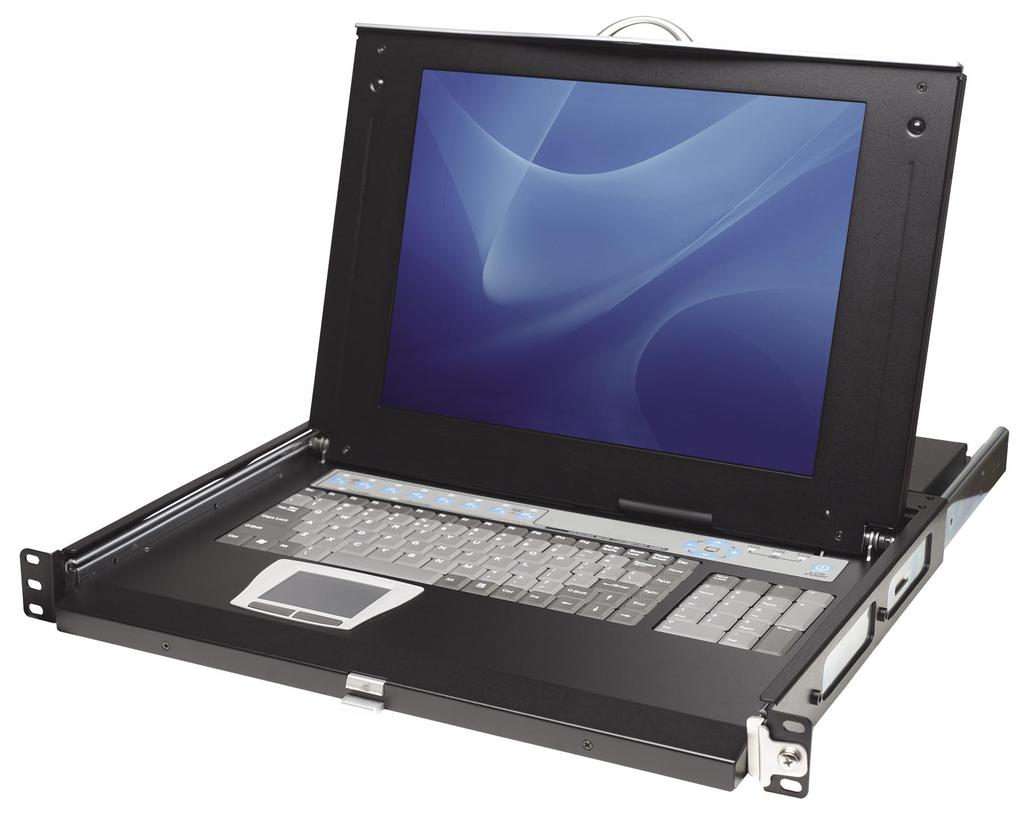
3 1. INTRODUCTION Thank you for purchasing the INTELLINET NETWORK SOLUTIONS Rackmount Console KVM Switch, Model (15 LCD, 8-port); Model (15 LCD, 16-port); Model (17 LCD, 8-port); or Model (19 LCD, 8-port). With a keyboard mouse, LCD panel and KVM switch module housed in an industrystandard 19 1U- or 2U-height rack drawer, the console saves you as much as a third of the space needed for a rack cabinet. And when the console is cascaded with other INTELLINET NETWORK SOLUTIONS KVM switch modules to increase server management capacity, you save even more space. Flip-open 15, 17 or 19 LCD panels support VGA resolution up to 1280 x 1024 without any degradation. The advanced VGA circuit design guarantees smooth and flicker-free switching from one computer to another with cable lengths up to 100 ft. / 30 m (tested with high-quality UL2919-rated, low-loss and shielded cables). With the on-screen display (OSD) menu, you can name your computers, switch to a computer from a list, easily configure settings and view the name of the selected computer on-screen with a programmable time interval. Plus, the OSD menu shows the system status throughout operation. All KVM switch modules come with a universal CEN36 connector for connection between the console drawer and a KVM switch module. This modularized design offers maximum flexibility, as you can choose and swap the modules to fit your needs. A KVM switch module can also be used as an independent KVM switch. This user manual shows you how to set up and operate the KVM switch. (For instructions on assembling and positioning the console drawer and the switch in a rack, refer to the separate Rackmount Console KVM Switch quick installation guide.) Follow the instructions in this user manual and you ll soon be enjoying these additional popular features: Integrated LCD console, keyboard, mouse and KVM switch module for sturdy rack-mount installation with tilt-free, two-piece rear bracket and extension kit Manage/control 8 or 16 computers from one keyboard, monitor and mouse Standard 19 1U or 2U rack drawer Fits rack cabinets with depth from 67.5 to 80.5 cm (26 5/8 to 31 5/8 in.) Locking mechanism locks the drawer when pulled out, pushed in or folded down Full 105-key, low-profile, sturdy keyboard Ergonomic handrest design Auto-scan automatically selects computers sequentially Supports Microsoft IntelliMouse (Pro) Supports both PS/2 and serial mice 3-in-1 space-saving cables Programmable scan filters unused computers Store system settings and name entries to non-volatile memory INTRODUCTION 3
4 Password security protects computers from unauthorized use Hotkey functions allow easy computer access Keyboard states automatically saved and restored when switching computers Operating system independent, transparent to all applications Plug and Play system configuration Keyboard and mouse can be hot plugged at any time DDC2B compatible Includes 6 ft. (1.8 m) PS/2 connection cable (plus 6 ft. [1.8 m] USB connection cable for Models and ) Lifetime Warranty Use the chart below for cross-referencing the different INTELLINET NETWORK SOLUTIONS Rackmount Console KVM Switch models with their various manufacturer part/reference numbers and specifications. Console/ KVM Rear Brkt. KVM Model Drawer Module & Ext. Kit Console Port KVM Package No. Part No. Part No. Part No. Size Type Ports Ht. Contents Console Transa PRO 15 IMM108D REK7 15 PS/2 8 1U Rear brkt. & ext. kit KVM Switch Module Transa PRO 15 IKM116D REK7 15 PS/2 16 2U Power supply 6 PS/2 cable Combo Console Transa PRO 17 IUM108D REK7 17 (USB and/ 8 1U Rear brkt. & ext. kit or PS/2) KVM Switch Module Combo Power supply Transa PRO 19 IUM108D REK7 19 (USB and/ 8 1U 6 PS/2 cable or PS/2) 6 USB cable Overview The combination of console and KVM switch module offers the latest and the most efficient way of controlling server rooms and multiple computers. With models of KVM switch modules available to control from eight to 136 servers at the console or at another set of consoles up to 100 ft. away it s the ultimate tool for server management. The variety of models of KVM switch modules available including the four INTELLINET NETWORK SOLUTIONS models addressed in this user manual present different computer interface options, which are listed below and shown in the images that follow. Standard models feature three connectors: for PS/2 keyboard, PS/2 mouse and monitor (HDB15). Hybrid (PS/2 + USB) models feature connectors for PS/2 keyboard, PS/2 mouse, USB (keyboard + mouse) and monitor (HDB15). Slim PS/2 models feature special 3-in-1 connectors for PS/2 keyboard, mouse and monitor (HDB15). 4 INTRODUCTION
5 INTRODUCTION 5
6 Configurations KVM switch modules are available with four, eight (Models , and ) and 16 ports (Model ) with various interfaces. In applications that require a larger number of computers, the KVM switch modules can be cascaded in a master/slave configuration. NOTE: Throughout this user manual, master refers to the KVM switch module that connects directly to the console drawer; slave refers to a KVM switch module that has its console port connected to a master s PC-x port. Slaves only exist in cascade configuration. Single KVM Switch Module Configuration: Combined with a console, the KVM switch module can be connected to multiple computers with keyboard, mouse and monitor cables as shown at right. KVM Switch Module in Cascade (Master/Slave) Configuration: You can connect a second level of one or more KVM switches modules to a master unit. Cascade configuration expands system ability, allowing you to select computers connected to the master or slaves. There is only one master that connects to the console directly operated by a user. Once connected, the KVM switch modules automatically configure themselves to either master or slave. Slaves of different KVM switch modules can be mixed in cascade configuration as shown here. 6 INTRODUCTION
7 2. INSTALLATION Device Connection Standard Models (Model ): Determine the port number of each computer. For computers using a PS/2 mouse, connect the computer s mouse and keyboard cables to the connectors marked with a mouse and keyboard, respectively, as shown. Repeat this step for PC-1 through PC-8. For computers using a serial mouse, connect the DB9-to-mini-DIN6 adapter (included with the switch) to the computer mouse port, then use PS/2 cables to connect the mouse to the KVM switch module. Connect the computer s monitor cable to the HD-DB-15 VGA connector. NOTE: This function is only available for PC-7 and PC-8 marked with two mice. Hybrid (PS/2 + USB) Models: With a hybrid, you can connect to a computer using either a PS/2 or USB port. To a USB computer: Use a USB A-B cable to connect from one of the PC ports to the USB port of a computer (A connector, flat connector), as shown below. The computer can be a USB-ready PC, Sun, HP server or Mac. INSTALLATION 7
8 To a PS/2 computer: Connect a PS/2 Y adapter, which comes with the unit, to the PS/2 port on the PC side, then use two mini-din6 male-to-male cables for the keyboard and mouse, as shown below. There are two mini-din6 female connectors on the PS/2 Y adapter marked for the keyboard and mouse. NOTE: Be sure not to swap the connections. To a laptop computer: In most cases, all you need is one PS/2 male-to-male cable connecting the KVM switch module and your laptop, as shown below; the Y adapter is not necessary. However, as some laptop computers do not follow the industry standard, check your laptop s user manual for details. Slim Models (Models , and ): Use only the cables shown at right. Connection from a slim KVM module to a PS/2 computer or a USB computer is shown below. For PS/2 computers connected to IMM and IUM models (Models , , ). For USB computers connected to IUM models (Models , ). 8 INSTALLATION
9 A Module as a Slave or a Stand-Alone KVM Switch A slave KVM switch module can be mounted to the inside of the rear uprights of a rack cabinet using the rear brackets (which come with all units except IKM001), with computer connectors facing to the rear, as well. NOTE: The connectors (keyboard and mouse) at the local port on the rear of the KVM module are not applicable when the module is connected to the TFT LCD drawer by the CEN36 connector. When the CEN36 connector is not connected to the TFT LCD drawer, the KVM switch module acts as a rear-mount stand-alone KVM switch module. The VGA ports (local and remote) can be connected to external VGA monitors at any time. Initial Power-Up Make sure all computers and KVM switch modules are powered down during installation. You must power up the master before turning on any other devices. For a single KVM switch module: 1. Connect a power adapter (output power = 12 V DC) to the master. 2. Turn on the computers. For cascaded KVM switch modules: 1. Connect a power adapter (O/P = 12 V DC) to the master. 2. Connect power adapters (O/P = 9 12V DC) to all slaves. 3. Turn on the computers. NOTE: After the initial power-up, you can hot-plug additional powered-down computers or a slave KVM switch module without turning off already-connected computers. 3. OPERATION Push Buttons A computer can be selected by pressing the push button directly, by issuing hotkey commands or by activating the OSD (on-screen display) window. The indicator changes to reflect the computer port selected (red). The indicator flashes red when it is in either Auto Scan or Manual Scan mode. NOTE: For 16-port modules (Model ), 1 8 are for the lower row of eight ports and A H are for the higher/upper row of eight ports. Port 1 and Port A share the same button: If Port 1 is already selected, tap its button to select OPERATION 9
10 Port A. If Port 1 is not selected, press and hold the 1 button on the console panel for two seconds to select Port A. The OSD menu and hotkeys are also available for computer selection. K/M Reset: K/M Reset solves most problems developed by the keyboard, the mouse, device replacement or a change of configuration. Press both the front-panel 1 and 2 buttons for two seconds to re-configure the whole system without turning off either the switch module or any computer. Auto Scan: The KVM switch module has an easy-to-use feature to start auto-scanning. Press both the front-panel 7 and 8 buttons for two seconds to start Auto Scan. (For 4-port models, press 3 and 4 instead.) On-Screen Display (OSD) Operation By hitting the left Control key twice within two seconds, you ll see the hotkey menu if it is enabled (an OSD option). Or, by hitting the left Control key three times within two seconds, you ll see a KVM menu showing a list of the computers with corresponding port numbers, names and status. The port number of the selected computer is displayed in red (as on the console panel) at the right corner of the OSD menu. A device name is green if it has power and is ready for operation. It s white if it has no power. The OSD menu updates the color when it is activated. Press the Page Up or Page Down keys to view another eight computers. Use the up/down arrow keys, 1 8 or A H to highlight a computer, and the Enter key to select it. Or, press the Escape (ESC) key to exit the OSD and remove the OSD menu from the display; the status window returns to the display 10 OPERATION
11 and indicates the currently selected computer or operating status. A triangle mark (4) to the right of a name indicates the port is cascaded to a slave. The number to the left of the triangle mark shows the number of ports the slave has; e.g., 84 for an 8-port switch. The Enter key brings you one level down, and another screen pops up listing the names of the computers on that slave. The name of the slave will be shown at the upper-right corner of the OSD menu. It is useful to group computers and still be able to see the group name. An eye icon (N) to the right of a name indicates the computer is selected to be monitored in Scan mode. On the OSD, this icon can be switched on or off by using the F2 function key. Press the ESC key to exit the OSD and return to the selected computer; the computer name is also shown on the screen. Function Keys: Function keys are used to access/activate a number of popular features. F1 is used to edit the name (up to 14 characters) entered for a computer or a slave. First, highlight a port, then press F1 followed by a name entry. Valid characters are A Z, 0 9 and the hyphen (dash) character. (Lowercase letters are converted to uppercase.) Press the Delete (Backspace) key to delete one character at a time. Non-volatile memory stores all name entries until you change them, even if the unit is powered down. F2 is used to switch the N of a computer on or off. First, use the up/down arrow keys to highlight the computer, then press F2 to switch its eye icon on or off. If Scan Type is Ready PC +N, only the active and N-selected computers will be displayed sequentially in Scan mode. F3 is used to lock a computer to prevent unauthorized access. To lock a device, highlight it, then press F3. Next, enter up to four characters (as defined above) followed by Enter as new password. A security-enabled device is marked with a lock (œ) following its port number. To permanently disable the security function from a locked device, highlight it, press F3, then enter the password. To temporarily access a locked device, highlight it and press Enter. The OSD will prompt you for the password. After entering the correct password, you are allowed access to the device. The device is automatically re-locked once you switch to another port. During Scan mode, the OSD skips password-protected devices. F4 is used to display a pop-up screen presenting additional function options, most of which are marked with a 4 indicating there are even more options available. Using the up/down arrow keys, select the functions and press Enter. Available options will be shown in the middle of the screen, and can be selected using the same procedure. Press the Escape key to exit at any time. Auto Scan: In this mode, the KVM switch module automatically switches from one active computer to the next (sequentially) at a fixed interval. During Auto OPERATION 11
12 Scan, the OSD displays the name of the selected computer. When Auto Scan detects any keyboard or mouse activity, it suspends the scanning until the activity stops, then resumes with the next computer in sequence. To abort Auto Scan, press the left Control key twice, or press any front-panel button. Scan Type and Scan Rate set the scan pattern. Scan Type (F4:More\Scan Type) determines if scanned computers must also be N-selected. Scan Rate (F4:More\Scan Rate) sets the display interval when a computer is selected before selecting the next one. Manual Scan: This mode lets you scan through active (powered-on) computers one by one using keyboard control. Scan Type (F4:More\Scan Type) determines if scanned computers must also be N-selected. Press the up arrow key to select the previous computer; press the down arrow key to select the next computer. Press any other key to abort the Manual Scan mode. Audio Stick: An optional multimedia module can be linked to the back of each KVM switch module for selecting microphone and stereo speaker signals. There are two options for Audio Stick: On and Off. When set to On, audio selection follows computer selection. When set to Off, audio selection stops following computer selection. It is useful if you want to listen to a particular computer s audio signal while operating other computers. The non-volatile memory stores the Audio Stick setting. Scan Type: This presents three further options. Ready PC +N lets you scan through active and N-selected computers in Scan mode. Ready PC lets you scan through active computers in Scan mode. N Only lets you scan (in Scan mode) through any N-selected computer regardless of computer power status. The non-volatile memory stores the Scan Type setting. Scan Rate: This sets the duration of a computer displayed in Auto Scan mode. The options range from three to eight seconds. The non-volatile memory stores the Scan Rate setting. Keyboard Speed: This offers a keyboard typematic setting that overrides the similar settings in BIOS and Windows. Available speed options are Low, Middle, Fast and Faster (10, 15, 20 and 30 characters/second, respectively). The non-volatile memory stores the Keyboard Speed setting. Hotkey Menu: When you hit the left Control key twice within two seconds, the hotkey menu appears, displaying a list of hotkey commands if the option is on. The hotkey menu can be turned off if you prefer not to see it when the left Control key is hit twice. The non-volatile memory stores the Hotkey Menu setting. CH Display: This presents two further options. Auto Off means that, after you select a computer, the port number and the name of the computer will appear on the screen for three seconds, then disappear automatically. 12 OPERATION
13 Always On means that the port number and the name of a selected computer and/or OSD status is displayed on the screen all the time. The non-volatile memory stores the CH Display setting. Position: The position of the selected computer name and/or OSD status is displayed on screen during the operation. The choices are Upper Left, Upper Right, Lower Left, Lower Right and Middle. The exact display position varies with different VGA resolutions: The higher the resolution, the higher the display position. The non-volatile memory stores the Position setting. Country Code for Sun (for Slim USB + PS/2 and Hybrid USB + PS/2 models only: Models and ): Sun keyboards of different languages have different layouts. The Rackmount Console KVM Switch is able to emulate a Sun keyboard for a specific language type or country; e.g., Arabic, Belgian, U.S. Select the proper country code that matches all of your Sun computers. Max. Resolution (for Slim USB + PS/2 and Hybrid USB + PS/2 models only: Models and ): You can adjust the monitor resolution under this sub-menu. Options are 1024 x 768, 1280 x 1024, 1600 x 1200, 1920 x 1440 and DDC2B Disable. F5 (for Slim USB + PS/2 and Hybrid USB + PS/2 models only: Models and ): This is to switch the Sun mark of a port on or off, indicating the computer is a Sun server. Sun servers have more keys on the keyboard than PACIFIC a PC. When a Sun-marked port is selected, the KVM switch starts to translate the keys from a PS/2 keyboard to a Sun keyboard. See Sun Keyboard Mapping (Section 6) for details. ESC, or the Escape key, is pressed to exit the OSD. Hotkey Commands Hotkey commands are a short keyboard sequence to select a computer, to activate a computer scan and so forth. The KVM switch module interprets keystrokes for hotkeys all the time. A hotkey sequence starts by pressing the left Control key twice followed by one or two keystrokes. A built-in buzzer generates a high-pitch beep for a correct hotkey command and one low-pitch beep for an error. A bad key sequence will not forward a command to the selected computer. NOTE: When entering numbers, do not use the numeric keypad on the right side of the keyboard. The short-form hotkey command menu can be set as an OSD function (F4:more\ Hotkey Menu) to appear every time the left Control key is pressed twice. OPERATION 13
14 To select a computer by hotkey command, you need to know its port number, which is determined by the KVM switch module connection. For a computer connected to a master, its port is represented by the PC port label (1 8 or A H). For a computer connected to a slave, two characters represent its port. The first character is the port number of the master unit (1 8); the second is the port number of the slave (1 8 or A H). Note that only a master s PC-1 through PC-8 ports can be connected to a slave. For example, pressing (left) Control/Control/7 selects a computer connected to Port 7 of the master. Pressing (left) Control/Control/6/C selects a computer connected to Port C of a slave connected to Port 6 of the master. To start Auto Scan, which automatically scans active (powered-on) computers one by one at a fixed interval, press (left) Control/Control/F1. When Auto Scan detects any keyboard or mouse activity, it suspends scanning until the activity stops, then resumes with the next computer in the sequence. The length of the Auto Scan interval (Scan Rate) is adjustable (as explained below). To abort Auto Scan, press the left Control key twice. NOTE: Scan Type determines whether N-marked computers are to be displayed during Auto Scan. Manual Scan (left) Control/Control/F2 enables you to manually switch between active computers. Press the up/down arrows to select the previous or the next computer in sequence; press any other key to abort Manual Scan. To adjust Scan Rate (left) Control/Control/F3 set the duration before switching to the next computer in Auto Scan. The KVM switch module sounds one to four beeps to indicate the scan interval: 3, 8, 15 or 30 seconds. To adjust the keyboard typematic rate (characters/second), press (left) Control/ Control/F4. This setting overrides that of BIOS and other operating systems. The KVM switch module generates one to four beeps corresponding to 10, 15, 20 and 30 characters/second, respectively. Audio Stick (left) Control/Control/F5 is an optional multimedia module that can be linked to the back of each KVM switch module for selecting microphone and stereo speaker signals. There are two options for Audio Stick: On and Off. When set to On, audio selection follows computer selection. When set to Off, audio selection stops following computer selection. It s useful if you want to listen to a particular computer s audio signal while operating other computers. The KVM switch module generates one (on) or two (off) beeps. 4. CASCADE CONFIGURATION Connection Before connecting a device (a computer or a slave KVM switch module) to the master KVM switch module under power, you must turn off the device. 14 CASCADE CONFIGURATION
15 NOTE: The master must have at least as many PC-x ports as the slave; e.g., if an IKM108D is the master, another IKM108D can be a slave, but not an IKM116D (see the reference on Page 5). The ports PC-1 through PC-8 can be connected to either a computer or a slave s local (or console) port, as shown at right. The ports PC-A through PC-H can only be connected to computers. NOTE: Only a master s PS/2 PC ports (not USB ports) can be connected to a slave s local (or console) port for cascade application. The maximum number of computers that can be controlled by a master/slave configuration with all 8-port units is 64: eight slaves, each connected to eight computers. OSD Menu: After the cascade connections are complete, you should re-activate the OSD menu to check if the master recognizes the slaves. A triangle mark (4) is placed to the right of the channel name, indicating the port is connected to a slave and not a computer. A number to the left of the 4 represents the slave model; e.g., 84 for an 8-port switch module. Change Configuration while Running A device (a computer or a KVM switch module) at any PC-x port can be changed at any time after initial power-up. If you change any of the PC-1 to PC-8 ports connections from a computer to a slave or vice versa, or replace the devices of a port, the OSD will update this change the next time it is activated. NOTE: Any new device must be turned off before it is connected to the master. CASCADE CONFIGURATION 15
16 5. MULTI-ACCESS MODEL A multi-access console KVM switch (IKM2108D, IKM2116D) features a pair of console ports, facilitating access to multiple computers from both a local and a remote location. An example of the practicality of this feature is the ability to access all computers in a configuration from inside a server room when you need to physically access the computers as when performing a software upgrade while being able to manage the computers outside the server room for daily use. NOTE: The four Rackmount Console KVM Switches covered by this user manual (INTELLINET NETWORK SOLUTIONS Models , , and ) are not multi-access models. Connection Connected to a TFT LCD Drawer: The remote console is available for a second set of keyboard, mouse and monitor. Stand-Alone: Both the remote and the local consoles are available for a keyboard, mouse and monitor connection. Operation At power-up, the multi-access KVM switch module is in idle mode, broadcasting a VGA signal and detecting for keyboard and mouse activity. User LEDs (A and B) are both red, indicating the KVM switch module is not in use. When keyboard or mouse activity is detected at one console (remote or local), the KVM switch module immediately blocks the other console from accessing the computer. Only one LED (remote or local), at the left side of the panel, remains lit, indicating the KVM switch module is under user operation. In the meantime, keyboard LEDs (Num/Caps/Scroll Lock) of the other console start to flash as its access is denied and the monitor is blocked from a VGA signal for security reasons. After the user has finished his operation for a period of time (i.e., User Timeout), the multi-access KVM switch module returns to idle mode. User Timeout has four options: 5 sec, 30 sec, 60 sec and HOLD. Select HOLD when you plan to access the KVM switch module for a long time. Pressing Scroll Lock twice forces the KVM switch module to return to idle mode immediately. User Timeout is available in the OSD menu by pressing function key F4 under the sub-menu More. NOTE: The Keyboard Speed option is not available for multi-access models. 16 MULTI-ACCESS MODEL
17 6. SUN/MAC KEYBOARD MAPPING IGM108D and IGM116D models emulate a Sun keyboard and mouse when a computer is marked with a Sun in the OSD menu by function key F5. A Sun keyboard has more keys than a standard PS/2 keyboard. These extra keys are simulated by pressing the right Control key followed by one of the function keys on the PS/2 keyboard. For example, press the right Control key, then press function key F7 to activate Open for a Sun computer. From PS/2 Map to Sun Map to Mac keyboard keyboard keyboard right Control 1 right Control 2 right Control 3 note right Control 4 power right Control F1 Stop right Control F2 Again right Control F3 Props right Control F4 Undo right Control F5 Front right Control F6 Copy right Control F7 Open right Control F8 Paste right Control F9 Find right Control F10 Cut Print Screen F13 Scroll Lock F14 Pause Break F15 right Control H Help right right right left left left Compose right Alt Alt Graph right Option left Alt Alt left Option NOTE: For Sun, the switch module does not support the Low Power option under Power Off Select after the command (right) Control 4. SUN/MAC KEYBOARD MAPPING 17
18 7. TROUBLESHOOTING Before troubleshooting any problem, ensure that all cables are properly connected and well seated. Check that keyboard and mouse cables are not swapped. Label and bundle the cables for each computer to avoid confusion when they re connected to the KVM switch module. Problem Nothing works. VGA monitor works fine, but the keyboard and touchpad don t work. No screen image, or no OSD menu. Possible Cause Bad connection at the CEN36 connectors. Another keyboard or mouse is connected to the rear of the KVM module (marked Local ) when the CEN36 connector is connected to the KVM drawer. The connection inside the KVM drawer has come loose due to vibration. A computer is on but not selected. The external power supply is not connected; there is no power to the KVM switch module. Remedial Actions Push the assembled drawer and the KVM module box firmly together, leaving only 8 mm (5/16 ) space in between. Be sure they re secured by two screws. If the CEN36 connector on the KVM module connects to a KVM drawer, its local console should not connect to any keyboard or mouse. Verify the KVM drawer is bad by disconnecting it from the KVM module (the CEN36 connector is not connected). Connect a keyboard, mouse and monitor to the Local port on the KVM module and connect another computer to any of the PC ports, and use the KVM module as a stand-alone KVM switch. Turn on a computer and select it by the front push buttons. Power up the system via the external power supply. Select a computer with a front push button. A red rectangle, part of the OSD function, should pop up displaying the port number as the system is properly powered. Connect a VGA monitor to the Local port at the rear and check if the VGA signal presents. 18 TROUBLESHOOTING
19 Problem Unable to operate USB-ready Sun server. Keyboard error on boot. Alphabets on the TFT LCD display are blurred or have shadows. Master/slave does not work. Keyboard strokes are shifted. The up/down arrow keys don t work in Manual Scan. The OSD menu is not in the proper position. Possible Cause Incorrect KVM module. Loose keyboard connection. Improper resolution settings. Improper installation procedures. The computer was in shifted state when last switched. All PCs are off, or only one PC is turned on. The Scan mode works for powered-on computers only. Scan Type is N- selected, but no PC is N-selected in the OSD. The resolution of the menu is fixed; its size varies as computer VGA resolution changes. Remedial Actions Use only the hybrid PS/2 + USB KVM module. Bring up the OSD menu, move the light bar to the port, press F5 to set the Sun mark on. Make sure the keyboard cables are well seated. Set the VGA resolution of the computers to 1024 x 768 with Large Font for the best performance. Make sure slave s console is connected to the master s PC-1 PC-8 port. Only PS/2 ports can be used for cascading. Press and hold the 1 and 2 push buttons to initiate K/M reset. Turn off any/all power to the slave (unplug all cables) before connecting it to the master. Press both Shift keys. Turn the computers on. Press any other key to abort the Manual Scan mode. Set the proper Scan Type in the OSD and determine which PCs are N- selected. Use F4:More\Position to select UL (upper-left) or UR (upper-right). The OSD menu may appear near the middle of the screen when LL (lower-left) or LR (lower-right) is selected. TROUBLESHOOTING 19
20 Problem Auto Scan doesn t switch PCs; plus, the KVM switch module beeps occassionally and the red indicator flashes. Double OSD images in the cascade configuration. Computer can t use serial mouse. Can t select a computer connected to a slave. Occasionally, the KVM switch module fails to function. Possible Cause All PCs are off or only one PC is turned on. Scan mode works only for powered computers. Scan Type is N-selected, but no powered PC is N-selected in the OSD. Improper slave connection procedure. Loose mouse adapter. Incorrect mouse adapter. Incorrect PC port connection. Improper master unit connection. Improper slave unit connection. Too many levels of slaves. The system is not getting enough power. Remedial Actions Turn on the computers. Set the proper Scan Type in the OSD and determine which PCs are N-selected. Press the left Control key twice to abort Auto Scan. Press any front button to select a PC, and Auto Scan stops. Press buttons 1 and 2 for two seconds to activate K/M reset. Turn off any/all power to the slave (unplug all cables) before connecting it to the master. Secure the mouse adapter to the computer s COM port. Use only the mouse adapter that comes with the unit. The mouse conversion is only effective at PC ports 7 and 8. Only master ports PC-1 PC-8 can be connected to slaves. Connect the slave console port to PC-1 PC-8 ports of the master. Only one level of slave units is allowed. Bring up the OSD again to check if the master recognizes the slave connection. Look for the 4 and the number before it. Make sure the external power supply is properly connected. 20 TROUBLESHOOTING
21 8. SPECIFICATIONS Model : Standards PS/2 General PC connections: 8 Console connections: 1 PC port connectors: - Keyboard: 8 PS/2 - Mouse: 8 PS/2, serial (includes adapters for two ports) - Monitor: HD15 male Console port connectors: keyboard, PS/2; mouse, PS/2; monitor, HD15 male Computer selection: via buttons, hotkeys and Windows switching software client Max. number of cascadable PCs: 64 (when cascaded with models of same type) OSD: yes Automatic scan interval: 3, 8, 15, 30 seconds Programmable scan pattern Cable length max.: 30 m (100 ft.) at console; 30 m (100 ft.) at PC ports VGA bandwidth: 1920 x 1440, DDC2B LCD KVM drawer connector: CEN36 Video resolution: max x 768 FCC Class B, CE, RoHS Power 12 V DC, 3 A (when connected to LCD drawer); 9 12 V DC, 500 ma (when not connected) Power consumption: max. 500 ma LCD Panel Specifications Active display area: x (mm) Pixel pitch (mm): (H) x (V) Model : Standards PS/2 General PC connections: 16 Console connections: 1 PC port connectors: - Keyboard: 16 PS/2 - Mouse: 16 PS/2, serial (includes adapters for two ports) - Monitor: HD15 male Console port connectors: keyboard, PS/2; mouse, PS/2; monitor, HD15 male Resolution: 1024 x 60/70/75 Hz Color pixel arrangement: RGB vertical strip Display mode: normally white Brightness (cd/m^2): 250 (center) Contrast ratio: 350:1 Display colors: 16.2M (RGB 6-bits + FRC data) User control: OSD control (auto-saving) Input signal: RGB analog, H/V separate Plug-n-Play VESA: VESA DDC 1/2B Power consumption (max): 33 W (normal operation/typical) Viewing angle (typical): (H); (V) Backlight unit: 2 CCFLs edge-light (top/bottom) Power supply input voltage: full range, V AC Environmental KVM module dimensions: 40 (H) x 404 (W) x 114 (D) mm (1.6 x 15.9 x 4.5 in.) Weight: 19.4 kg (42.7 lbs.) Operating temperature: 0 50 C ( F) Operating humidity: 0 95% Storage temperature: C ( F) Storage humidity: 95% RH Package contents Rackmount Console KVM Switch Rear bracket and extension kit Power adapter One 6 ft. (1.8 m) PS/2 3-in-1 cable Console quick installation guide KVM Switch Module user manual Additional cables required (sold separately) PS/2 3-in-1 KVM Cable, 6 ft. (1.8 m): PS/2 3-in-1 KVM Cable, 10 ft. (3.0 m): Computer selection: via buttons, hotkeys and Windows switching software client Max. number of cascadable PCs: 136 (when cascaded with models of same type) OSD: yes Automatic scan interval: 3, 8, 15, 30 seconds Programmable scan pattern Cable length max.: 30 m (100 ft.) at console; 30 m (100 ft.) at PC ports VGA bandwidth: 1920 x 1440, DDC2B LCD KVM drawer connector: CEN36 Video resolution: max x 768 FCC Class B, CE, RoHS SPECIFICATIONS 21
22 Power 12 V DC, 3 A (when connected to LCD drawer); 9 12 V DC, 500 ma (when not connected) Power consumption: max. 500 ma LCD Panel Specifications Active display area: x (mm) Pixel pitch (mm): (H) x (V) Resolution: 1024 x 60/70/75 Hz Color pixel arrangement: RGB vertical strip Display mode: normally white Brightness (cd/m^2): 250 (center) Contrast ratio: 350:1 Display colors: 16.2M (RGB 6-bits + FRC data) User control: OSD control (auto-saving) Input signal: RGB analog, H/V separate Plug-n-Play VESA: VESA DDC 1/2B Power consumption (max): 33 W (normal operation/typical) Viewing angle (typical): (H); (V) Backlight unit: 2 CCFLs edge-light (top/bottom) Power supply input voltage: full range, V AC Model : Standards PS/2 USB Compatible with Windows, MAC and Unix General PC connections: 8 Console connections: 1 PC port connectors: keyboard, mouse, monitor: HD15 x 8 Console port connectors: - Keyboard: PS/2 - Mouse: PS/2 - Monitor: HD15 female Computer selection: via buttons, hotkeys and Windows switching software client Max. number of cascadable PCs: 64 (when cascaded with models of same type) OSD: yes Automatic scan interval: 3, 8, 15, 30 seconds Programmable scan pattern Cable length max.: 30 m (100 ft.) at console; 15 m (50 ft.) at PC ports for PS/2; 5 m (16 ft.) at PC ports for USB VGA bandwidth: 1920 x 1440, DDC2B LCD KVM drawer connector: CEN36 Video resolution: max x 768 FCC Class B, CE, RoHS Power 12 V DC, 3 A (when connected to LCD drawer); 9 12 V DC, 500 ma (when not connected) Environmental KVM module dimensions: 80 (H) x 404 (W) x 114 (D) mm (3.2 x 15.9 x 4.5 in.) Weight: 18.8 kg (42.7 lbs.) Operating temperature: 0 50 C ( F) Operating humidity: 0 95% Storage temperature: C ( F) Storage humidity: 95% RH Package contents Rackmount Console KVM Switch Rear bracket and extension kit Two PS/2 to USB adapters Power adapter One 6 ft. (1.8 m) PS/2 3-in-1 cable Console quick installation guide KVM Switch Module user manual Additional cables required (sold separately) PS/2 3-in-1 KVM Cable, 6 ft. (1.8 m): PS/2 3-in-1 KVM Cable, 10 ft. (3.0 m): Power consumption: max. 500 ma LCD Panel Specifications Active display area: x (mm) Pixel pitch (mm): (H) x (V) Resolution: 1280 x 60/70/75 Hz Color pixel arrangement: RGB vertical strip Display mode: normally white Brightness (cd/m^2): 260 (center) Contrast ratio: 450:1 Display colors: 16.2M (RGB 6-bits + FRC data) User control: OSD control (auto-saving) Input signal: RGB analog, H/V separate Plug-n-Play VESA: VESA DDC 1/2B Power consumption (max): 37 W (normal operation/typical) Viewing angle (typical): (H); (V) Backlight unit: 4 CCFLs edge-light (top/bottom) Power supply input voltage: full range, V AC Environmental KVM module dimensions: 40 (H) x 404 (W) x 114 (D) mm (1.6 x 15.9 x 4.5 in.) Weight: 18.8 kg (41.44 lbs.) Operating temperature: 0 50 C ( F) Operating humidity: 8 95% Storage temperature: C ( F) Storage humidity: 95% RH Package contents Rackmount Console KVM Switch 22 SPECIFICATIONS
23 Rear bracket and extension kit Power adapter 6 ft. (1.8 m) PS/2 3-in-1 cable 6 ft. (1.8 m) USB 3-in-1 cable Console quick installation guide KVM Switch Module user manual Model : Standards PS/2 USB Compatible with Windows, MAC and Unix General PC connections: 8 Console connections: 1 PC port connectors: keyboard, mouse, monitor: HD15 x 8 Console port connectors: - Keyboard: PS/2 - Mouse: PS/2 - Monitor: HD15 female Computer selection: via buttons, hotkeys and Windows switching software client Max. number of cascadable PCs: 64 (when cascaded with models of same type) OSD: yes Automatic scan interval: 3, 8, 15, 30 seconds Programmable scan pattern Cable length max.: 30 m (100 ft.) at console; 15 m (50 ft.) at PC ports for PS/2; 5 m (16 ft.) at PC ports for USB VGA bandwidth: 1920 x 1440, DDC2B LCD KVM drawer connector: CEN36 Video resolution: max x 768 FCC Class B, CE, RoHS Power 12 V DC, 3 A (when connected to LCD drawer); 9 12 V DC, 500 ma (when not connected) Power consumption: max. 500 ma LCD Panel Specifications Active display area: x (mm) Pixel pitch (mm): (H) x (V) Resolution: 1280 x 60/70/75 Hz Additional cables required (sold separately): PS/2 3-in-1 KVM Cable, 6 ft. (1.8 m): PS/2 3-in-1 KVM Cable, 10 ft. (3.0 m): USB 3-in-1 KVM Cable, 6 ft. (1.8 m): USB 3-in-1 KVM Cable, 10 ft. (3.0 m): Color pixel arrangement: RGB vertical strip Display mode: normally white Brightness (cd/m^2): 250 (center) Contrast ratio: 500:1 Display colors: 16.7M (RGB 8-bits data) User control: OSD control (auto-saving) Input signal: RGB analog, H/V separate Plug-n-Play VESA: VESA DDC 1/2B Power consumption (max): 40 W (normal operation/typical) Viewing angle (typical): (H); (V) Backlight unit: 4 CCFLs edge-light (top/bottom) Power supply input voltage: full range, V AC Environmental KVM module dimensions: 40 (H) x 404 (W) x 114 (D) mm (1.6 x 15.9 x 4.5 in.) Weight: 21.0 kg (46.3 lbs.) Operating temperature: 0 50 C ( F) Operating humidity: 8 95% Storage temperature: C ( F) Storage humidity: 95% RH Package contents Rackmount Console KVM Switch Rear bracket and extension kit Power adapter 6 ft. (1.8 m) PS/2 3-in-1 cable 6 ft. (1.8 m) USB 3-in-1 cable Console quick installation guide KVM Switch Module user manual Additional cables required (sold separately) PS/2 3-in-1 KVM Cable, 6 ft. (1.8 m): PS/2 3-in-1 KVM Cable, 10 ft. (3.0 m): USB 3-in-1 KVM Cable, 6 ft. (1.8 m): USB 3-in-1 KVM Cable, 10 ft. (3.0 m): SPECIFICATIONS 23

24 Are you completely satisfied with this product? Please contact your INTELLINET NETWORK SOLUTIONS dealer with comments or questions. Copyright INTELLINET NETWORK SOLUTIONS All products mentioned are trademarks or registered trademarks of their respective owners.
Table of Contents. Cascade Configuration
 Table of Contents Introduction Overview 1 Features 1 Configurations 2 Installation Cables 5 Device Connection 6 Initial Power-up 7 Operation Pushuttons 9 LEDs 9 OSD (On-Screen Display) Operation 10 Hotkey
Table of Contents. Integra KVM Switch Modules
 Table of Contents s Introduction Overview 1 Features 3 Configurations 4 Installation Device Connection 6 Initial Power-up 10 Operation Push Buttons 11 OSD (On-Screen Display) Operation 12 Hotkey Commands
Rackmount Console quick install guide
 Rackmount Console KVM Switch quick install guide Model 501620 INT-501620-QIG-0408-01 INTRODUCTION Thank you for purchasing the INTELLINET NETWORK SOLUTIONS Rackmount Console KVM Switch, Model 501620 (15
Table of Contents. ServerLink Eco KVM Rack Drawer. Overview... 1 Features... 2 Configurations... 3 Front Panel Control... 5
 Table of Contents Introduction Overview... 1 Features... 2 Configurations... 3 Front Panel Control... 5 Installation Rack Cabinet... 6 Device Connection for LKS-1017E... 8 Device Connection for LKS-8017E
RACKMOUNT CONSOLE KVM SWITCH QUICK INSTALLATION GUIDE
 RACKMOUNT CONSOLE KVM SWITCH QUICK INSTALLATION GUIDE MODELS 521796, 521871, 523561 & 523578 INT-521796/521871/523561/523578-QIG-0307-01 INTRODUCTION Thank you for purchasing the INTELLINET NETWORK SOLUTIONS
Keyboard/Mouse/Monitor SharingSwitch. User's Manual SV431 SV831 SV431D SV831D SV1631D SV832DS SV1632DS
 Keyboard/Mouse/Monitor SharingSwitch User's Manual SV431 SV831 SV431D SV831D SV1631D SV832DS SV1632DS Table of Contents Introduction Overview 1 Features 2 Configurations 3 Installation Device Connection
Introduction Automatic Mouse Conversion. Overview. High Video Quality. Two-Console KVM Switches (Optional)
") ------------------------ Introduction Automatic Mouse Conversion Overview The SH-6580 is only 1U Four in one control center (KVM switch, KEYBOARD, LCD and MOUSE). It can control up to 8 PCs or 64 PCs by
------------------------ Introduction Automatic Mouse Conversion Overview The SH-6580 is only 1U Four in one control center (KVM switch, KEYBOARD, LCD and MOUSE). It can control up to 8 PCs or 64 PCs by
Table of Contents. Introduction Introduction. Overview. Introduction. One-Console KVM Switches. Two-Console KVM Switches
 Table of Contents ------------------------ Introduction Introduction Introduction Overview... 1 Features.... 3 Configurations......4 Installation Device Connection......7 Initial Power-up........9 Optional
Introduction. Overview. Automatic Mouse Conversion. High Video Quality. Two-Console KVM Switches (Optional)
") ------------------------ Introduction Overview The SH-6510 is only 1U Four in one control center (KVM switch, KEYBOARD, LCD and MOUSE). It can control up to 8 PCs or 64 PCs by cascade. There is no interface
------------------------ Introduction Overview The SH-6510 is only 1U Four in one control center (KVM switch, KEYBOARD, LCD and MOUSE). It can control up to 8 PCs or 64 PCs by cascade. There is no interface
KEYPORT MILLENNIA USB Series
 KEYPORT MILLENNIA USB Series Models: USB-8, USB-16 User Manual Connect-Tek, Inc. 39-20 24th Street Long Island City N.Y. 11101 Phone: (718) 729-3700 Fax: (718) 729-3972 www.connect-tek.com Table of Contents
KEYPORT MILLENNIA USB Series
 KEYPORT MILLENNIA USB Series Models: USB-04, USB-8, USB-16 User Manual Connect-Tek, Inc. 39-20 24th Street Long Island City N.Y. 11101 Phone: (718) 729-3700 Fax: (718) 729-3972 www.connect-tek.com Table
Table of Contents. Overview...3. Features...3. Packing List...4. Assembly...6. Installation...9. Front Panel...10
 Table of Contents INTRODUCTION...1 CONSOLE Overview...3 Features...3 Packing List...4 Assembly...6 Installation...9 Front Panel...10 Replaceable Keyboard and Touch Pad...11 LCD Specification...13 Please
SMK585 1U rackmount. With 8 Ports KVM Switch
 SMK585 1U rackmount Monitor Keyboard Drawer With 8 Ports KVM Switch TABLE OF CONTENTS Content FEATURES...1 BASIC SPECIFICATION...2 DISPLAY...2 PACKAGE CONTENTS...2 TECHNICAL SPECIFICATIONS...3 SYSTEM REQUIREMENT...3
SMK525 / SMK585 / SMK595
 SMK525 / SMK585 / SMK595 RACK MOUNTABLE 1 / 8 / 16 PORT PS2 KVM SWITCH USER S MANUAL Rev 1.2 TABLE OF CONTENTS INTRODUCTION...1 FEATURES....1 PACKAGE CONTENTS..... 2 TECHNICAL SPECIFICATIONS...3 SYSTEM
Your Rackmount Display Solution. 1U Keyboard / Monitor + 8 / 16 Ports. BHK Black Hawk Series USER S MANUAL. Ver.1
 Your Rackmount Display Solution 1U Keyboard / Monitor + 8 / 16 Ports BHK Black Hawk Series USER S MANUAL Ver.1 Content Specification....3 Rackmount Installation......4 Product Detail 5 On Screen Display.....6
KEYPORT MILLENNIA Series. User Manual. Table of Contents. Introduction Product Overview...1 Product Features. 3 Configurations 4
 Table of Contents KEYPORT MILLENNIA Series Introduction Product Overview....1 Product Features. 3 Configurations 4 Installation Device Connections...7 Initial Power-Up..9 User Manual Operation Front Panel
Limited Warranty. All brand names and registered trademarks are the property of their respective owners.
 Limited Warranty IN NO EVENT SHALL THE DIRECT VENDOR'S LIABILITY FOR DIRECT OR INDIRECT, SPECIAL, INCIDENTAL OR CONSEQUENTIAL DAMAGES, LOSS OF PROFIT, LOSS OF BUSINESS, OR FINANCIAL LOSS WHICH MAY BE CAUSED
User s Manual 2005 All Right Reserved
 Wide Screen SMK 4 Series User s Manual 2005 All Right Reserved Table of Content SPECIFICATION....1 FEATURES... 2 TECHNICAL SPECIFICATIONS...3 SYSTEM REQUIREMENT..3 CABLE DIAGRAMS.4 HARDWARE INSTALLATION
Keyboard/Mouse/Monitor SharingSwitch. User's Manual SV231
 Keyboard/Mouse/Monitor SharingSwitch User's Manual SV231 Table of Contents Introduction Overview 1 Features 1 Installation Device Connection 2 Initial Power-Up 6 Operation Front Panel Push Buttons 6 Hot
SMK520 / SMK580 / SMK590 RACK MOUNTABLE 1 / 8 / 16 PORT PS2 KVM SWITCH USER S MANUAL
 SMK520 / SMK580 / SMK590 RACK MOUNTABLE 1 / 8 / 16 PORT PS2 KVM SWITCH USER S MANUAL Rev 1.1 TABLE OF CONTENTS INTRODUCTION...1 FEATURES....1 PACKAGE CONTENTS..... 2 TECHNICAL SPECIFICATIONS...3 SYSTEM
Introduction. Table of Content. Overview. Automatic Mouse Conversion. Introduction
 ----------------- Introduction Introduction Table of Content Overview......1 Features....2 Installations Console Connection....3 Computers Connection... 4 Initial Power-up....6 Operations Front Panel operation.........7
Table of Contents. Overview...2. Features...2. Packing List...3. Assembly...5. Installation...8. Front Panel...9
 Table of Contents INTRODUCTION...1 SERVERLINK LCD CONSOLE Overview...2 Features...2 Packing List...3 Assembly...5 Installation...8 Front Panel...9 Replaceable Keyboard and Touch Pad... 10 LCD Specification...
INTRODUCTION...1 FEATURES...1 PACKAGE CONTENTS... 1 TECHNICAL SPECIFICATIONS...2 SYSTEM REQUIREMENT..3 CABLE DIAGRAMS.3 PRODUCT DETAILS 4
 TABLE OF CONTENTS INTRODUCTION...1 FEATURES....1 PACKAGE CONTENTS... 1 TECHNICAL SPECIFICATIONS....2 SYSTEM REQUIREMENT..3 CABLE DIAGRAMS.3 PRODUCT DETAILS 4 HARDWARE INSTALLATION 5 USAGE 5 ON SCREEN DISPLAY
TABLE OF CONTENTS Chapter 1 Introduction... 3 Chapter 2 Installation... 7 Chapter 3 Operation... 15
 TABLE OF CONTENTS Chapter 1 Introduction... 3 1.1 Features... 3 1.2 Package Contents... 4 1.3 Technical Specifications... 5 Chapter 2 Installation... 7 2.1 System Requirements... 7 2.2 Cable Diagrams...
Table of Content Introduction Installations Operations Appendices Troubleshooting Installation
 Table of Content Introduction Overview.....1 Features..2 Installations Console Connection....3 Computers Connection.....8 Initial Power-up.....12 Operations Front Panel operation......13 Hot-key commands..........13
LevelOne. User Manual KVM-0811 / KVM /16-Port PS2 KVM Switch
 LevelOne KVM-0811 / KVM-1611 8/16-Port PS2 KVM Switch User Manual Table of Contents 1. INTRODUCTION...1 FEATURES...1 PACKAGE CONTENT...2 SYSTEM REQUIREMENTS...2 TECHNICAL SPECIFICATIONS...3 FRONT PANEL...4
4 / 8 / 16 PORT PS2 KVM SWITCH USER S MANUAL
 STACKABLE 4 / 8 / 16 PORT PS2 KVM SWITCH USER S MANUAL PC / Mac / Sun Multi Platform Rev 1.1 TABLE OF CONTENTS INTRODUCTION...1 FEATURES....1 PACKAGE CONTENTS..... 2 TECHNICAL SPECIFICATIONS...3 SYSTEM
User s manual 19 1U RACKMOUNT CONTROL CENTER. Rack-KVM in-1 TABLE OF CONTENTS INTRODUCTION... (KVM switch, Keyboard, LCD display, touch pad)
") Rack-KVM9000 User s manual 4-in-1 (KVM switch, Keyboard, LCD display, touch pad) 19 1U RACKMOUNT CONTROL CENTER Rev 1.1 TABLE OF CONTENTS INTRODUCTION... FEATURES.... PACKAGE CONTENTS..... TECHNICAL SPECIFICATIONS...
Rack-KVM9000 User s manual 4-in-1 (KVM switch, Keyboard, LCD display, touch pad) 19 1U RACKMOUNT CONTROL CENTER Rev 1.1 TABLE OF CONTENTS INTRODUCTION... FEATURES.... PACKAGE CONTENTS..... TECHNICAL SPECIFICATIONS...
SYNERGY GLOBAL INC. Toll Free : Fax :
 SYNERGY GLOBAL INC Toll Free : 1-888-865-6888 Fax : 510-226-8968 Email : info@rackmountmart.com LCD1U15-03 series & LCD1U17-10 series User s manual 4-in-1 (KVM switch, Keyboard, LCD display, touch pad)
1U 8-Port KVM Module for 1UCABCONS 1U 16-Port KVM Module for 1UCABCONS
 1U 8-Port KVM Module for 1UCABCONS 1U 16-Port KVM Module for 1UCABCONS CAB831HDU CAB1631HDU *actual product may vary from photos DE: Bedienungsanleitung - de.startech.com FR: Guide de l'utilisateur - fr.startech.com
8-Port / 16-Port KVM SWITCH User s Manual
 8-Port / 16-Port KVM SWITCH User s Manual Version 1.0 1. Introduction The 8-Port/16-Port KVM Switch are high quality and durable systems that will allow you to control 8/16 host computers (or servers)
8-Port / 16-Port Rackmount user manual Models &
 8-Port / 16-Port Rackmount KVM Switch user manual Models 524629 & 524643 Shown: 16-Port, Model 524643 INT-524629/524643-UM-0309-01 524629_524643_01_man.indd 1 3/9/09 9:22:10 AM 524629_524643_01_man.indd
LevelOne. User Manual KVM-0831/KVM /16-Port Combo KVM Switch w/ Expansion Slot. Ver
 LevelOne KVM-0831/KVM-1631 8/16-Port Combo KVM Switch w/ Expansion Slot User Manual Ver. 1.0-0706 ii Safety FCC This equipment has been tested and found to comply with Part 15 of the FCC Rules. Operation
DVI KVM Switch user manual Model
 DVI KVM Switch user manual Model 156066 INT-156066-UM-0808-01 introduction Thank you for purchasing the INTELLINET NETWORK SOLUTIONS DVI KVM Switch, Model 156066. This convenient device lets you control
KVM USB / PS/2. Model INT UM
 KVM Extender USB / PS/2 user manual Model 524476 INT-524476-UM-1208-01 Thank you for purchasing this INTELLINET NETWORK SOLUTIONS KVM Extender USB / PS/2, Model 524476. Supporting distances of up to 150
4/8/16 Port 1U Rack Mount VGA USB KVM Switch with OSD SV431DUSBU SV831DUSBU SV1631DUSBU SV831DUSBUK SV1631DUSBUK
 4/8/16 Port 1U Rack Mount VGA USB KVM Switch with OSD SV431DUSBU SV831DUSBU SV1631DUSBU SV831DUSBUK SV1631DUSBUK *SV831DUSBU shown DE: Bedienungsanleitung - de.startech.com FR: Guide de l'utilisateur -
TWO-CONSOLE (One Local, One CAT5 Remote) 8 port / 16 port 19 RACK MOUNTABLE PS/2 KVM SWITCH USER S MANUAL
 8 port / 16 port 19 RACK MOUNTABLE PS/2 KVM SWITCH USER S MANUAL") TWO-CONSOLE (One Local, One CAT5 Remote) 8 port / 16 port 19 RACK MOUNTABLE PS/2 KVM SWITCH USER S MANUAL Rev 1.0 TABLE OF CONTENTS INTRODUCTION...1 FEATURES....2 PACKAGE CONTENTS..... 3 TECHNICAL SPECIFICATIONS...4
TWO-CONSOLE (One Local, One CAT5 Remote) 8 port / 16 port 19 RACK MOUNTABLE PS/2 KVM SWITCH USER S MANUAL Rev 1.0 TABLE OF CONTENTS INTRODUCTION...1 FEATURES....2 PACKAGE CONTENTS..... 3 TECHNICAL SPECIFICATIONS...4
Refurbished 1U 19in Rackmount LCD Console with Integrated 8 Port KVM Switch
 Refurbished 1U 19in Rackmount LCD Console with Integrated 8 Port KVM Switch Product ID: RKCONS1908R The RKCONS1908R Refurbished 1U 19-inch Rack Mount LCD Console provides centralized control for servers
Table of Contents INTRODUCTION STREAMLINE CONSOLE. Overview..1. Overview..2. Features...2. Packing List..3. Assembly.. 4 ~ 6.
 Table of Contents INTRODUCTION Overview..1 STREAMLINE CONSOLE Overview..2 Features...2 Packing List..3 Assembly.. 4 ~ 6 Installation 7 Front Panel.. 8 Specifications.9 Please read this manual thoroughly
(DS / DS-14202)
") 8-Port / 16-Port USB and PS/2 Combo-KVM Switch User s Manual (DS-13202 / DS-14202) Index 1. INTRODUCTION... 4 2. SPECIFICATIONS... 5 3. SYSTEM REQUIREMENTS... 6 4. INSTALLATION... 6 4.1. FRONT VIEW...
8-Port / 16-Port USB and PS/2 Combo-KVM Switch User s Manual (DS-13202 / DS-14202) Index 1. INTRODUCTION... 4 2. SPECIFICATIONS... 5 3. SYSTEM REQUIREMENTS... 6 4. INSTALLATION... 6 4.1. FRONT VIEW...
4/ 8/ 16 Port 1U Rack Mount USB VGA KVM Switch with OSD
 4/ 8/ 16 Port 1U Rack Mount USB VGA KVM Switch with OSD SV431DUSB SV831DUSB / SV831DUSBGB SV1631DUSB / SV1631DUSBGB *actual product may vary from photos DE: Bedienungsanleitung - de.startech.com FR: Guide
KVM PS/2 user manual Model
 KVM Extender PS/2 user manual Model 524353 INT-524353-UM-1008-04 Thank you for purchasing this INTELLINET NETWORK SOLUTIONS KVM Extender PS/2, Model 524353. Supporting distances of up to 150 meters (450
4PortKeyboard/Mouse/Monitor SharingSwitchUSB-PS/2. User'sManual SV431H
 4PortKeyboard/Mouse/Monitor SharingSwitchUSB-PS/2 User'sManual SV431H Table of Contents Introduction Overview 1 Features 1 Installation PC BIOS Notice 2 Adhesive Rubber Feet 3 Console Connection 3 Computer
Toll Free: Tel: Fax:
 Toll Free: 1-888-865-6888 Tel: 510-226-8368 Fax: 510-226-8968 Email: sales@rackmountmart.com LCD Drawer User Manual This manual, covering various aspects of the equipment such as installation, setup and
User Manual. Rack Dual Rail CAT5 LCD KVM Console (8 Port /16 Port/24 Port /32 Port) User Manual
 User Manual") Rack Dual Rail CAT5 LCD KVM Console (8 Port /16 Port/24 Port /32 Port) User Manual www.szkinan.com @all right reserved Shenzhen Kinan Technology Co.,Ltd Printing date: 2015/05 Version: V3.0-1 - Contents
Rack Dual Rail CAT5 LCD KVM Console (8 Port /16 Port/24 Port /32 Port) User Manual www.szkinan.com @all right reserved Shenzhen Kinan Technology Co.,Ltd Printing date: 2015/05 Version: V3.0-1 - Contents
User's Manual. LCD KVM Console Rack Drawer. RoHS
 User's Manual LCD KVM Console Rack Drawer Features and functions may be added or changed after the manual was written. Please visit our website to download the latest version of manual for reference. RoHS
1U 17" Rackmount LCD Console with Integrated 16 Port IP KVM Switch
 1U 17" Rackmount LCD Console with Integrated 16 Port IP KVM Switch Product ID: CABCONS1716I This 1U Rack Mount LCD KVM Console features an integrated 16 Port Multi-Platform IP KVM Switch module, 17in active
1+1 Console 8/16/32 ports Modularize CAT-5 KVM Switch (Console Free)
") 1+1 Console 8/16/32 ports Modularize CAT-5 KVM Switch (Console Free) (w/ Optional Add-on IP Module / CAT-5 Module) User s Manual C o n t e n t s 1. INTRODUCTION... 2 1.1 MAIN FEATURES... 3 1.2 PACKAGE
1+1 Console 8/16/32 ports Modularize CAT-5 KVM Switch (Console Free) (w/ Optional Add-on IP Module / CAT-5 Module) User s Manual C o n t e n t s 1. INTRODUCTION... 2 1.1 MAIN FEATURES... 3 1.2 PACKAGE
CL6700. Single Rail LCD Console with USB Peripheral Support (USB / HDMI / DVI / VGA)
") CL6700 Single Rail LCD Console with USB Peripheral Support (USB / HDMI / DVI / VGA) The CL6700 features an integrated 17.3" (CL6700MW) or 19 (CL6700N) LED-backlit LCD panel, a full keyboard, and a touchpad
CL6700 Single Rail LCD Console with USB Peripheral Support (USB / HDMI / DVI / VGA) The CL6700 features an integrated 17.3" (CL6700MW) or 19 (CL6700N) LED-backlit LCD panel, a full keyboard, and a touchpad
Sylphit-Duo DSK-Series. KVM Drawer (with integrated KVM switch)
") Sylphit-Duo DSK-Series KVM Drawer (with integrated KVM switch) User Guide Version 1.0 Technology Corporation Rackit Technology Corporation 274 Madison Avenue, New York, NY 10016 Tel: (212) 679-0050 Fax:
Sylphit-Duo DSK-Series KVM Drawer (with integrated KVM switch) User Guide Version 1.0 Technology Corporation Rackit Technology Corporation 274 Madison Avenue, New York, NY 10016 Tel: (212) 679-0050 Fax:
Daisy Chain KVM Console KVM-17CZ User Manual
 Daisy Chain KVM Console KVM-17CZ www.szkinan.com @all right reserved Shenzhen Kinan Technology Co.,Ltd Printing date: 2014/10 Version: V3.0 Product Description KVM-17CZ is a console integrates keyboard,
1. BRIEF INTRODUCTION...
 -1- Table of contents 1. BRIEF INTRODUCTION... 3 2. PACKAGE INSIDE... 3 3. FEATURES. 3 4. SPECIFICATIONS. 4 5. INSTALLATION. 5 6. USAGE ( Hotkey Commands and OSD Operations ).. 9-2 - BRIEF INTRODUCTION
Rackmount LCD Console - 1U - 17in Screen - US Keyboard p
 Rackmount LCD Console - 1U - 17in Screen - US Keyboard - 1080p Product ID: RKCOND17HDEU This 1U LCD console offers a space-saving solution for managing and monitoring your DVI or VGA servers and KVM switches
Rack Mount CAT5 KVM Switch (8Port/16 Port/32 Port) User Manual
 User Manual") Rack Mount CAT5 KVM Switch (8Port/16 Port/32 Port) User Manual www.szkinan.com @all right reserved Shenzhen Kinan Technology Co., Ltd Printing date:2015/04 Version: V2.0-1- Contents Overview... 3 Description...
Rack Mount CAT5 KVM Switch (8Port/16 Port/32 Port) User Manual www.szkinan.com @all right reserved Shenzhen Kinan Technology Co., Ltd Printing date:2015/04 Version: V2.0-1- Contents Overview... 3 Description...
8/16-Port Enterprise KVM Switch
 User s Manual 8/16-Port Enterprise KVM Switch Model No.: SP218D/SP226D World Wide Web: www.micronet.com.tw ; www.micronet.info Certifications FCC This equipment has been tested and found to comply with
Foldaways. GFA Series. 1U Rack-Mount FoldAways with LCD Monitor, Keyboard, Touchpad; 8-Port KVM Switch on Qualified Models USER S MANUAL
 Foldaways GFA Series 1U Rack-Mount FoldAways with LCD Monitor, Keyboard, Touchpad; 8-Port KVM Switch on Qualified Models USER S MANUAL VER. 1.0C MAY 2008 No part of this manual may be reproduced without
User Manual. CV-401 / 801 / U Rackmount PS/2 KVM Switch
 User Manual CV-401 / 801 / 1601 1U Rackmount PS/2 KVM Switch 1. Table Of Content 1. Table of Content P.1 2. Introduction P.2 3. Features P.2 4. Package Content P.3 5. Optional Accessories P.4 6. Peripheral
2-Port Dual Monitor DVI KVM Switch, TAA, GSA with Audio and USB 2.0 Hub, Cables included
 2-Port Dual Monitor DVI KVM Switch, TAA, GSA with Audio and USB 2.0 Hub, Cables included MODEL NUMBER: B004-2DUA2-K Description Tripp Lite's B004-2DUA2-K 2-Port Dual Monitor DVI KVM Switch, TAA, GSA allows
Venus Series Stand Alone & Modular Combo-free KVM Switch User Manual
 Venus Series Stand Alone & Modular Combo-free KVM Switch User Manual Rev 2.0 Venus Series User Manual Table of Contents Table of Contents... I 1. Introduction... 1 1.1 Features... 1 1.2 Package Contents...
User Manual. VGA KVM Switch, PS2 and USB. GCS1722/GCS1724 PART NO. M1258 / M
 User Manual VGA KVM Switch, PS2 and USB GCS1722/GCS1724 PART NO. M1258 / M1259 www.iogear.com - 1 - 2013 IOGEAR. All Rights Reserved. PKG-M1258 / M1259 IOGEAR, the IOGEAR logo, are trademarks or registered
IC-1504 / IC-1508 / IC-1516
 LCD KVM SWITCH IC-1504 / IC-1508 / IC-1516 USER MANUAL - 1 - LCD MONITOR SPECIFICATIONS Size 15 inch Screen Type TFT Contrast 500:1 Brightness 250 cd/m 2 View Angle 110 Resolution 1024x768@75Hz Response
Rack Mount 17 &19 Console User Manual
 Rack Mount 17 &19 Console www.szkinan.com @all right reserved Shenzhen Kinan Technology Co.,Ltd Printing Date:2014/08 Version: V2.0 Description Single port console integrate the monitor, keyboard and mouse
Cabinet Console. 1U Cabinet Console with 15" TFT Monitor 1U Cabinet Console with 17" TFT Monitor 1U Cabinet Console with 19" TFT Monitor
 Cabinet Console 1U Cabinet Console with 15" TFT Monitor 1U Cabinet Console with 17" TFT Monitor 1U Cabinet Console with 19" TFT Monitor 1UCABCONS 1UCABCONS17 1UCABCONS19 Instruction Manual Actual product
CS-64U. User Manual
 User Manual CS-64U Read this guide thoroughly and follow the installation and operation procedures carefully in order to prevent any damage to the units and/or any devices that connect to them. This package
8 / 16 port combo KVM Switch 1+1 Console 8 / 16 port combo KVM Switch User Manual
 8 / 16 port combo KVM Switch 1+1 Console 8 / 16 port combo KVM Switch User Manual V2.0 2007.4.25 C o n t e n t s 1. Introduction... 16H4 1.1 Back Panel... 4 1.2 Main Features... 17H5 1.3 Package Contents...
KVM I KVM I KVM-1160 USER'S MANUAL
 KVM-1 040 I KVM-1 080 I KVM-1160 USER'S MANUAL TABLE OF CONTENTS 1 FEATURES 1 PACKAGE CONTENTS 1 TECHNICAL SPECIFICATIONS 2 SYSTEM REQUIREMENT 3 CABLE DIAGRAMS 4 PRODUCT DETAILS 4 HARDWARE INSTALLATION
8-Port DVI/USB KVM Switch with Audio and USB 2.0 Peripheral Sharing, 1U Rack-Mount, Dual- Link, 2560 x 1600
 8-Port DVI/USB KVM Switch with Audio and USB 2.0 Peripheral Sharing, 1U Rack-Mount, Dual- Link, 2560 x 1600 MODEL NUMBER: B024-DUA8-DL Highlights Cascade up to 3 levels and control up to 512 computers
USB KVM Switch USER MANUAL CS62US / CS64US
 USB KVM Switch USER MANUAL CS62US / CS64US EMC Information FEDERAL COMMUNICATIONS COMMISSION INTERFERENCE STATEMENT: This equipment has been tested and found to comply with the limits for a Class B digital
Rack Mount LCD KVM Assembly. Installer/User Guide
 Rack Mount LCD KVM Assembly Installer/User Guide Rack Mount LCD KVM Assembly Installer/User Guide Avocent, the Avocent logo and The Power of Being There are registered trademarks of Avocent Corporation
Cabinet Console 1UCABCONS 1UCABCONS17 1UCABCONS19. For the most up-to-date information, please visit:
 Cabinet Console 1UCABCONS 1UCABCONS17 1UCABCONS19 *actual product may vary from photo For the most up-to-date information, please visit: www.startech.com Manual Revision: 02/10/2011 FCC Compliance Statement
8-Port DVI/USB KVM Switch with Audio and USB 2.0 Peripheral Sharing, 1U Rack-Mount, Dual-Link, 2560 x 1600
 8-Port DVI/USB KVM Switch with Audio and USB 2.0 Peripheral Sharing, 1U Rack-Mount, Dual-Link, 2560 x 1600 MODEL NUMBER: B024-DUA8-DL Description Tripp Lite s B024-DUA8-DL DVI/USB KVM Switch eases multi-server
CL Port PS/2-USB VGA Dual Rail LCD KVM Switch with Daisy-Chain Port and USB Peripheral Support
 CL5808 8-Port PS/2-USB VGA Dual Rail LCD KVM Switch with Daisy-Chain Port and USB Peripheral Support The CL5808 Slideaway Dual Rail LCD KVM Switch is a control unit that allows access to multiple computers
CAT.5 COMBO-KVM SWITCH 8-PORT/16-PORT
 CAT.5 COMBO-KVM SWITCH 8-PORT/16-PORT Quick Installation Guide DS-15202 / DS-16202 1. System Requirements Hardware Local Host side : The following equipment must be equipped with each computer or server
2-Port / 4-Port COMBO FREE (USB&PS/2)
") 2-Port / 4-Port COMBO FREE (USB&PS/2) KVM SWITCH User s Manual Version 2.0 1. Introduction Thank you for your purchase of Combo Free KVM Switch! You now have a high quality, durable system that will enable
2-Port / 4-Port COMBO FREE (USB&PS/2) KVM SWITCH User s Manual Version 2.0 1. Introduction Thank you for your purchase of Combo Free KVM Switch! You now have a high quality, durable system that will enable
Section 12 LCD INTEGRATED KVM SWITCH - MODULAR. Modular LCD KVM Drawer. KVM Switches
 LCD INTEGRATED KVM SWITCH - MODULAR Modular LCD KVM Drawer IKM017-BK IKM019-BK IW-EXT3 17" LCD Base Unit 19" LCD Base Unit 3 Year Warranty Upgrade The 1RU 19 LCD integrated modular KVM switch is an ideal
1U 17 & 19 Rackmount LCD Console with 8 & 16 Port KVM Switch
 1U 17 & 19 Rackmount LCD Console with 8 & 16 Port KVM Switch RACKCONS1708 RACKCONS1716 RACKCONS1908 RACKCONS1916 RKCONS1708GB RKCONS1716GB RKCONS1908GB RKCONS1916GB RKCONS1708EU RKCONS1916EU *actual product
ComboCAT Port KVM Switch. User Guide. Rev 0.9
 ComboCAT 8-16- 32-Port KVM Switch User Guide Rev 0.9 Technology Corporation Rackit Technology Corporation 271 Madison Avenue, New York, NY 10016 Tel: (212) 679-0050 Fax: (212) 679-0040 1. 8 0 0. 6 3 6.
Single Rail LCD Console With 8/ 16 ports KVM User s Manual
 Single Rail LCD Console With 8/ 16 ports KVM User s Manual Index 1. INTRODUCTION.2 1.1 OVERVIEW.... 2 1.2 FEATURES......2 2. SPECIFICATIONS.3 2.1 GENERAL.....3 2.2 PACKAGE CONTENTS.........4 3. DESCRIPTION
8 Port Rackmount USB VGA KVM Switch w/ Audio (Audio Cables Included) StarTech ID: SV831DUSBAU
 StarTech ID: SV831DUSBAU") 8 Port Rackmount USB VGA KVM Switch w/ Audio (Audio Cables Included) StarTech ID: SV831DUSBAU The SV831DUSBAU 8 Port Rack Mount USB VGA KVM Switch (with Audio Cables Included) allows you to control up
8 Port Rackmount USB VGA KVM Switch w/ Audio (Audio Cables Included) StarTech ID: SV831DUSBAU The SV831DUSBAU 8 Port Rack Mount USB VGA KVM Switch (with Audio Cables Included) allows you to control up
Dual Rail AS-7100 & AS-9100 series LCD KVM User Manual
 KVM Discovery powered by Haitwin-Delphin Technologie GmbH, Kieselstraße 15, 41472 Neuss / Germany phone: 0049(0)2131/7421652 email: info@kvm-discovery.com Dual Rail AS-7100 & AS-9100 series LCD KVM User
WL-21701/21708/21716 User Reference Manual. Revision 1.3 (080717)
") WL-21701/21708/21716 User Reference Manual Revision 1.3 (080717) LCD Keyboard Drawer Specification for WL-21701/21708/21716 Chassis External Chassis Industrial Metal Frame Display LCD 17, 19" Diagonal
WL-21701/21708/21716 User Reference Manual Revision 1.3 (080717) LCD Keyboard Drawer Specification for WL-21701/21708/21716 Chassis External Chassis Industrial Metal Frame Display LCD 17, 19" Diagonal
KVM SYSTEMS KVM SYSTEMS
 KVM SYSTEMS 7 LCD KVM Drawer Page 6-3 Analog KVM Switch with DB15 Ports Page 6-5 IP KVM Switch with DB15 Ports Page 6-7 IP KVM Switch with Cat 5/6 Ports Page 6-9 KVM Switch Accessories Page 6-12 KVM SYSTEMS
Installation A B. Install each bracket using screws provided shown in Figure 1. Fix the KVM into the rack
 Installation screw A: M3.2 x 4.5 mm A B Cy r be Vie w screw B: M4 x 10 mm Install each bracket using screws provided shown in Figure 1. Fix the KVM into the rack Figure 1. Installing the bracket to the
KL1508A. 8-Port Cat 5 Dual Rail LCD KVM Switch with Daisy-Chain Port
 KL1508A 8-Port Cat 5 Dual Rail LCD KVM Switch with Daisy-Chain Port ALTUSEN KL1508A LCD KVM Switch features independently retractable, dual slide 17" or 19" LED-backlit LCD monitor and keyboard with built-in
Rack Dual Rail KVM Console (8 Ports /16 Ports) User Manual
 User Manual") Rack Dual Rail KVM Console (8 Ports /16 Ports) www.szkinan.com @all right reserved Shenzhen Kinan Technology Co.,Ltd Printing date:2013/03 Version: V1.1-1 - Contents Overview... 3 Descriptions... 3 Features...
Rack Dual Rail KVM Console (8 Ports /16 Ports) www.szkinan.com @all right reserved Shenzhen Kinan Technology Co.,Ltd Printing date:2013/03 Version: V1.1-1 - Contents Overview... 3 Descriptions... 3 Features...
Installation A B. Install each bracket using screws provided shown in Figure 1. Fix the KVM into the rack
 Installation screw A: M3.2 x 4.5 mm A B Cy r be Vie w screw B: M4 x 10 mm Install each bracket using screws provided shown in Figure 1. Fix the KVM into the rack Figure 1. Installing the bracket to the
KVM-U4 & KVM-U8. Users Guide. 8 Port VGA KVM Switch. 4 Port VGA KVM Switch CUSTOMER SUPPORT INFORMATION
 KVM-U4 & KVM-U8 4 Port VGA KVM Switch 8 Port VGA KVM Switch Users Guide CUSTOMER SUPPORT INFORMATION UMA 1180, Rev 1.1 Order toll-free in the U.S. 800-959-6439 FREE technical support, Call 714-641-6607
CD Console. Gemini 15 / 17 / 19 / 19W. SUN Microsystems. Benefits
 CD Console Modular KVM Design Scalable solution UP to 32 ports Integrate 18 models of KVM switches in 1U form factor to optimize space limitation Multi-platform Support The LCD console support multi-platforms:
1RU 17.3 LCD Console Drawer with Integrated DVI KVM Switch - 8 Port User Manual
 1RU 17.3 LCD Console Drawer with Integrated DVI KVM Switch - 8 Port User Manual Contents 1. Introduction... 3 1.1 Main Features... 3 1.2 Package Contents... 3 1.3 LED Panel... 4 1.3.1 Port LED Indications...
CD Console. Gemini 15 / 17 / 19. SUN Microsystems. Benefits
 CD Console Modular KVM Design Scalable solution UP to 32 ports Integrate 18 models of KVM switches in 1U form factor to optimize space limitation Multi-platform Support The LCD console support multi-platforms:
Technology Corporation. ADDERLINK X SERIES X2-MultiScreen
 ADDERLINK X SERIES X2-MultiScreen Multiple video, multiple RS232, keyboard, mouse and audio extender, with local access, giving sharp, bright and ultra high-resolution video images at distances up to 300m
User Manual CL
 User Manual CL-1200 Warning! This is a class A product. In a domestic environment this product may cause radio interference in which case the user may be required to take adequate measures. This equipment
If anything is damaged or missing, contact your dealer.
 User Manual CS-64A Read this guide thoroughly and follow the installation and operation procedures carefully in order to prevent any damage to the unit and/or any devices that connect to it. This package
4 Port KVM Switch. If anything is damaged or missing, contact your dealer.
 4 Port KVM Switch User Manual CS-84A Read this guide thoroughly and follow the installation and operation procedures carefully in order to prevent any damage to the units and/or any devices that connect
Installation A B. Install each bracket using screws provided shown in Figure 1. Fix the KVM into the rack
 Installation screw A: M3.2 x 4.5 mm A B Cy r be Vie w screw B: M4 x 0 mm Install each bracket using screws provided shown in Figure. Fix the KVM into the rack Figure. Installing the bracket to the KVM.
8 ports/16 ports USB/PS/2 Combo-KVM Switch
 8 ports/16 ports USB/PS/2 Combo-KVM Switch Manual DS-23200-2 DS-23300-2 PRODUCT MODEL LIST Model DS-23200-2 DS-23300-2 Specification 8 input (USB & PS/2), 1 output (USB), Supporting cascade & hub. 16 input
Installation A B. Install each bracket using screws provided shown in Figure 1. Fix the KVM into the rack
 Installation screw A: M3.2 x 4.5 mm A B Cy r be Vie w screw B: M4 x 10 mm Install each bracket using screws provided shown in Figure 1. Fix the KVM into the rack Figure 1. Installing the bracket to the
Industrial Rack-mount LCD KVM Drawer. User Manual. 8 -Port KVM Drawer 16-Port KVM Drawer
 Industrial Rack-mount LCD KVM Drawer User Manual 8 -Port KVM Drawer 16-Port KVM Drawer TABLE OF CONTENTS 4 Packing Contents 4 Safety Instructions 6 Introduction 6 Feature 8 Specification 10 Panel Description
1U 17" HD 1080p Dual Rail Rackmount LCD Console w/ Fingerprint Reader and Front USB Hub
 1U 17" HD 1080p Dual Rail Rackmount LCD Console w/ Fingerprint Reader and Front USB Hub StarTech ID: RACKCOND17HD The RACKCOND17HD Dual Rail LCD Rack Console lets you control server equipment from a centralized,
Dual User 16 Port 1U Rackmount PS/2 KVM Switch with OSD
 Dual User 16 Port 1U Rackmount PS/2 KVM Switch with OSD Product ID: SV1632DS A rock-solid, reliable KVM switch for mission-critical datacenter environments. StarTech.com s SV1632DS is the reliable solution