Orion XTender KVM Extender
|
|
|
- Jemimah McBride
- 6 years ago
- Views:
Transcription
 933-7673 Houston, Texas 77099 WWW.ROSE.")
1 Orion XTender KVM Extender INSTALLATION AND OPERATIONS MANUAL Stancliff Road Phone: (281) Houston, Texas
2
3 LIMITED WARRANTY Rose Electronics warrants the Orion XTender to be in good working order for one year from the date of purchase from Rose Electronics or an authorized dealer. Should this product fail to be in good working order at any time during this one-year warranty period, Rose Electronics will, at its option, repair or replace the Unit as set forth below. Repair parts and replacement units will be either reconditioned or new. All replaced parts become the property of Rose Electronics. This limited warranty does not include service to repair damage to the Unit resulting from accident, disaster, abuse, or unauthorized modification of the Unit, including static discharge and power surges. Limited Warranty service may be obtained by delivering this unit during the one-year warranty period to Rose Electronics or an authorized repair center providing a proof of purchase date. If this Unit is delivered by mail, you agree to insure the Unit or assume the risk of loss or damage in transit, to prepay shipping charges to the warranty service location, and to use the original shipping container or its equivalent. You must call for a return authorization number first. Under no circumstances will a unit be accepted without a return authorization number. Contact an authorized repair center or Rose Electronics for further information. ALL EXPRESS AND IMPLIED WARRANTIES FOR THIS PRODUCT INCLUDING THE WARRANTIES OF MERCHANTABILITY AND FITNESS FOR A PARTICULAR PURPOSE, ARE LIMITED IN DURATION TO A PERIOD OF ONE YEAR FROM THE DATE OF PURCHASE, AND NO WARRANTIES, WHETHER EXPRESS OR IMPLIED, WILL APPLY AFTER THIS PERIOD. SOME STATES DO NOT ALLOW LIMITATIONS ON HOW LONG AN IMPLIED WARRANTY LASTS, SO THE ABOVE LIMITATION MAY NOT APPLY TO YOU. IF THIS PRODUCT IS NOT IN GOOD WORKING ORDER AS WARRANTED ABOVE, YOUR SOLE REMEDY SHALL BE REPLACEMENT OR REPAIR AS PROVIDED ABOVE. IN NO EVENT WILL ROSE ELECTRONICS BE LIABLE TO YOU FOR ANY DAMAGES INCLUDING ANY LOST PROFITS, LOST SAVINGS OR OTHER INCIDENTAL OR CONSEQUENTIAL DAMAGES ARISING OUT OF THE USE OF OR THE INABILITY TO USE SUCH PRODUCT, EVEN IF ROSE ELECTRONICS OR AN AUTHORIZED DEALER HAS BEEN ADVISED OF THE POSSIBILITY OF SUCH DAMAGES, OR FOR ANY CLAIM BY ANY OTHER PARTY. SOME STATES DO NOT ALLOW THE EXCLUSION OR LIMITATION OF INCIDENTAL OR CONSEQUENTIAL DAMAGES FOR CONSUMER PRODUCTS, SO THE ABOVE MAY NOT APPLY TO YOU. THIS WARRANTY GIVES YOU SPECIFIC LEGAL RIGHTS AND YOU MAY ALSO HAVE OTHER RIGHTS WHICH MAY VARY FROM STATE TO STATE. NOTE: This equipment has been tested and found to comply with the limits for a Class A digital device, pursuant to Part 15 of the FCC Rules. These limits are designed to provide reasonable protection against harmful interference when the equipment is operated in a commercial environment. This equipment generates, uses, and can radiate radio frequency energy and, if not installed and used in accordance with the instruction manual, may cause harmful interference to radio communications. Operation of this equipment in a residential area is likely to cause harmful interference in which case the user will be required to correct the interference at their his own expense. IBM, AT, and PS/2 are trademarks of International Business Machines Corp. Microsoft and Microsoft Windows are registered trademarks of Microsoft Corp. Any other trademarks mentioned in this manual are acknowledged to be the property of the trademark owner. Copyright Rose Electronics All rights reserved. No part of this manual may be reproduced, stored in a retrieval system, or transcribed in any form or any means, electronic or mechanical, including photocopying and recording, without the prior written permission of Rose Electronics. Rose Electronics Part # MAN-CRVDVIQ Printed In the United States of America 1.7
4 FCC/IC STATEMENTS, EU DECLARATION OF CONFORMITY Product Orion XTender This equipment generates, uses and can radiate radio frequency energy and if not installed and used properly, that is in strict accordance with the manufacturer s instructions may cause interference to radio communication. It has been tested and found to comply with the limits for a Class A digital device in accordance with the specifications of Part 15 of FCC rules, which are designed to provide reasonable protection against such interference when the equipment is operated in a commercial environment. Operation of this equipment in a residential area is likely to cause interference, in which case the user will be required to take whatever measures necessary to correct the interference, at his/her own expense. Changes or modifications not expressly approved by the party responsible for compliance could void the user s authority to operate the equipment. This digital apparatus does not exceed the Class A limits for radio noise emission from digital apparatus set out in the Radio Interference Regulation of Industry Canada. Operation is subject to the following two conditions: 1- This device may not cause harmful interference 2- This device must accept any interference received including interference that may cause undesired operation. Le présent appareil numérique n émet pas de bruits radioélectriques dépassant les limites applicables aux appareils numériques de la classe A prescrites dans le Règlement sur le brouillage radioélectrique publié par Industrie Canada. CE Statement The product meets European Standard EMC: EN-55022:2006 Class A EN :2001 EN :2006 EN :2004 EN :2006
5 TABLE of CONTENTS Contents Page # Disclaimer... 2 System Introduction... 2 Features... 2 Compatibility... 3 Package contents... 3 System Overview... 5 Orion Xtender Models... 6 Status System Setup Configuration Operation Service Information Maintenance and Repair Technical Support Product Safety Figures Page # Figure 1. System Overview... 5 Figure 2. Various Applications... 29
6 INTRODUCTION Disclaimer While every precaution has been taken in the preparation of this manual, the manufacturer assumes no responsibility for errors or omissions. Neither does the manufacturer assume any liability for damages resulting from the use of the information contained herein. The manufacturer reserves the right to change the specifications, functions, or circuitry of the product without notice. The manufacturer cannot accept liability for damages due to misuse of the product or other circumstances outside the manufacturer s control. The manufacturer will not be responsible for any loss, damage, or injury arising directly or indirectly from the use of this product. System Introduction Thank you for choosing the Rose Electronics Orion XTender, a high-performance, long distance, multifunction digital KVM Extender. The product increases the distance between a source (computer, CPU) and its console (display, keyboard, mouse, and other peripheral devices). It is compatible with CATx (Twisted Pair) interconnect cables or fiber interconnect cables. The fiber models of the Orion XTender are especially suitable for environments with high electromagnetic activity, where electromagnetic interference can affect maximum distance and signal reliability. The modular structure of the Orion XTender product family accommodates a variety of applications by offering the flexibility of customization. Each extender card can be installed in one of four unique frame assemblies: 2, 4, 6, or 21 cards per frame. The DVI extenders support high resolution video up to 1920 x 1200 and USB-HID signals for mice, keyboards or other USB pointing devices. A multi-stage compression algorithm maximizes data flow and provides a consistently clear image quality for HD video signals. Several options are available for each module, including analog or digital audio, USB 2.0, VGA inputs and RS232 serial data transports. Cable distances up to 460 ft (140 m) with CATx or 10 km with fiber cables are supported. The system consists of two components: a Transmitter and a receiver. The Transmitter connects to a computer s DVI-D video output, USB keyboard and mouse ports, USB 2.0 device ports, audio input/output connectors and a serial port. The receiver can connect directly to DVI-D video displays, USB keyboards and mice, USB 2.0 devices, powered speakers, a microphone and/or serial device. Depending on the model, the Transmitter and receiver are connected with industry standard CATx or fiber cables. Features Superior image quality at all supported resolutions Transfer of DVI signals over distances up to 32,800 ft (10 km) via fiber, and up to 460 ft 140 via CATx Supports all monitor resolutions up to Hz / 60Hz Supports USB1.1/2.0 peripherals. Single-head and multi-head models available Four compact frame types are available: 2, 4, 6 or 21 cards per frame High mounting density using a 19 rack mount kit (up to 3 devices can be placed in a 19 /1U) All connectors on one side Power supply included Supports all operating systems Compatible with Orion X KVM Switches Optional: Two further USB-HID connections USB 2.0 transparent Digital audio interface ORION XTENDER QUAD INSTALLATION AND OPERATIONS MANUAL 2
7 VGA input Redundant power supply (load sharing) Serial interface (RS232) with analog audio Compatibility Computers Displays Keyboards Mouse Serial Audio USB PCs (all operating systems) DVI-D video to 1.65 Gbit/sec/channel All standard USB keyboards All standard USB mice Compatible devices up to 19.2KBaud Bi-directional CD quality stereo audio USB 2.0 devices Table 1. Compatible Devices Package contents 1 Your extender package contains the following items: KVM Extender pair (Transmitter Unit and Receiver Unit) in the chassis 1x (redundant 2x) 5VDC international power supply unit per KVM Extender unit 1x (redundant 2x) country specific power cord Quick Setup DVI video cable (1.8 m, DVI-D male-to-male) USB cable (1.8 m, type A to type B) If anything is missing, contact your dealer. Optional: Additional DVI, USB, Audio and Serial cables for CPU-to-Transmitter connections can be ordered separately. VGA to DVI converters are also available. VGA cable (1.8 m, VGA male to DVI-I male) Serial cable (1.8 m, D-Sub 9 male connector) 3 Orion Installation and Operations Manual
8 Stereo jack cable (1.6 m, 3.5 mm male connector) Additional content for upgrade module serial (RS422): Serial cable (1.8 m, D-Sub 9 male connector) Additional content for upgrade module Digital Audio: RCA cable (2.5 m, Cinch male connector) TOSLINK cable (1.8 m, F05 male connector) Additional content for upgrade module USB-HID: USB cable (1.8 m, USB type A to type B) Additional content for upgrade module PS/2: 2x PS/2 cable (1.8 m, 6-pole connector) Additional content for upgrade module USB 2.0 embedded: USB cable (1.8 m, USB type A to type B) Additional content for upgrade module USB 2.0: USB cable (1.8 m, USB type A to type B) ORION XTENDER INSTALLATION AND OPERATIONS MANUAL 4
 at the local site. The Receiver modules are installed in a chassis at the remote site.")
9 System Overview The Orion XTender consists of at least one Transmitter module and one Receiver module. The Transmitter modules are installed in an XTender chassis (2-fold, 4-fold, 6-fold or 21-fold) at the local site. The Receiver modules are installed in a chassis at the remote site. The Transmitter module is connected directly to the source (computer, CPU) using the supplied cables. The Receiver module is connected to the console peripherals (monitor, keyboard and mouse). Transmitter and Receiver modules communicate through interconnect cables. 5 Orion Installation and Operations Manual

10 MODELS Orion Xtender Models ORION XTENDER INSTALLATION AND OPERATIONS MANUAL 6

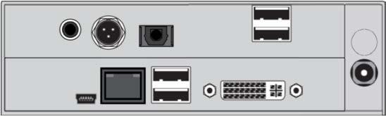
11 1 Service port 1 Service port 2 CATx port 2 CATx port 3 To CPU: USB-HID 3 To USB-HID devices 4 To CPU: DVI-D 4 To DVI monitorpos : 20 /806-IHSE/Besc hrei bung/geräteansichten/474- xx/t yp L- / R 474- BSH S / Service port 1 Service port 2 Fiber port 2 Fiber port 3 To CPU: USB-HID 3 To CPU: USB-HID devices 4 To CPU: DVI-D 4 To CPU: DVI-D devices 1 Service port 1 Service port 2 CATx port 2 CATx port 3 To CPU: USB-HID 3 To USB-HID devices 4 To CPU: DVI-D Dual-Link 4 To DVI Dual-Link monitorpos 7 ORION XTENDER INSTALLATION AND OPERATIONS MANUAL

12 1 Service port 1 Service port 2 CATx port 1 2 CATx port 1 3 CATx port 2 3 CATx port 2 4 To CPU: USB-HID 4 To USB-HID devices 5 To CPU: DVI-D 5 To DVI monitor 1 Service port 1 Service port 2 Fiber port 1 2 Fiber port 1 3 Fiber port 2 3 Fiber port 2 4 To CPU: USB-HID 4 To USB-HID devices 5 To CPU: DVI-D 5 To DVI monitor ORION XTENDER INSTALLATION AND OPERATIONS MANUAL 8
 1 Service port (KVM) 1 Service port 2 CATx port 2 CATx port 3 To CPU: USB-HID 3 To USB-HID devices 4 To CPU: DVI-I (VGA / DVI) 4 IR receiver for remote control 5 IR")
13 1 Service port (KVM) 1 Service port 2 CATx port 2 CATx port 3 To CPU: USB-HID 3 To USB-HID devices 4 To CPU: DVI-I (VGA / DVI) 4 IR Receiver for remote control 5 IR Receiver for remote control 5 To DVI monitor 6 Service port (DVI-I) 1 Service port (KVM) 1 Service port 2 CATx port 2 CATx port 3 To CPU: USB-HID 3 To USB-HID devices 4 To CPU: DVI-I (VGA / DVI) 4 IR receiver for remote control 5 IR Receiver for remote control 5 To DVI monitor 6 Service port (DVI-I) 9 ORION XTENDER INSTALLATION AND OPERATIONS MANUAL
 2 AES/EBU input (Mini-XLR) 2 AES/EBU output (Mini-XLR) 3 S/PDIF input (TOSLINK) 3 S/PDIF output (TOSLINK) 4 To CPU: USB-HID 4 To USB-HID devices ORION XTENDER INSTALLATION AND OPERATIONS")
14 1 To CPU: USB-HID 1 To USB-HID devices 1 To serial (D-Sub 9) 1 To serial (D-Sub 9) 2 Audio IN 2 Audio IN 3 Audio OUT 3 Audio OUT 4 To CPU: USB-HID 4 To USB-HID devices 1 S/PDIF input (RCA) 1 S/PDIF output (RCA) 2 AES/EBU input (Mini-XLR) 2 AES/EBU output (Mini-XLR) 3 S/PDIF input (TOSLINK) 3 S/PDIF output (TOSLINK) 4 To CPU: USB-HID 4 To USB-HID devices ORION XTENDER INSTALLATION AND OPERATIONS MANUAL 10
15 1 Service port 1 Service port 2 CATx port 2 CATx port 3 To CPU: USB To USB 2.0 devices 1 Service port 1 Service port 2 Fiber port 2 Fiber port 3 To CPU: USB To USB 2.0 devices 11 ORION XTENDER INSTALLATION AND OPERATIONS MANUAL
16 ` 1 To CPU: USB To USB 2.0 devices 1 To CPU: USB Audio IN 2 Audio OUT 3 To USB 2.0 devices 1 To serial (D-Sub 9) 1 To serial (D-Sub 9) 2 Audio IN 2 Audio IN 3 Audio OUT 3 Audio OUT 4 To CPU: USB To USB 2.0 devices 1 S/PDIF input (RCA) 1 S/PDIF output (RCA) 2 AES/EBU input (Mini-XLR) 2 AES/EBU output (Mini-XLR) 3 S/PDIF input (TOSLINK) 3 S/PDIF output (TOSLINK) 4 To CPU: USB To USB 2.0 devices. ORION XTENDER INSTALLATION AND OPERATIONS MANUAL 12
17 1 To serial (D-Sub 9) 1 To serial (D-Sub 9) 2 Audio IN 2 Audio IN 3 Audio OUT 3 Audio OUT 1 S/PDIF input (RCA) 1 S/PDIF output (RCA) 2 AES/EBU input (Mini-XLR) 2 AES/EBU output (Mini-XLR) 3 S/PDIF input (TOSLINK) 3 S/PDIF output (TOSLINK) 1 S/PDIF input (RCA) 1 S/PDIF output (RCA) 2 AES/EBU input (Mini-XLR) 2 AES/EBU output (Mini-XLR) 3 S/PDIF input (TOSLINK) 3 S/PDIF output (TOSLINK) 4 To serial (D-Sub 9) 4 To serial (D-Sub 9) 5 Audio IN 5 Audio IN 6 Audio OUT 6 Audio OUT 1 S/PDIF input (RCA) 1 S/PDIF output (RCA) 2 AES/EBU input (Mini-XLR) 2 AES/EBU output (Mini-XLR) 3 S/PDIF input (TOSLINK) 3 S/PDIF output (TOSLINK) 4 S/PDIF output (RCA) 4 S/PDIF input (RCA) 5 AES/EBU output (Mini-XLR) 5 AES/EBU input (Mini-XLR) 6 S/PDIF output (TOSLINK) 6 S/PDIF input (TOSLINK) 13 ORION XTENDER INSTALLATION AND OPERATIONS MANUAL
18 1 To serial (D-Sub 9) 1 To serial (D-Sub 9) 2 Audio IN 2 Analog Audio IN 3 Audio OUT 3 Audio OUT 4 To CPU: PS/2 mouse 4 To PS/2 mouse 5 To CPU: PS/2 keyboard 5 To PS/2 keyboard 1 To local PS/2 mouse 1 To PS/2 mouse 2 To local PS/2 keyboard 2 To PS/2 keyboard 3 To CPU: PS/2 mouse 4 To CPU: PS/2 keyboard 1 To serial (D-Sub 9) 1 To serial (D-Sub 9) ORION XTENDER INSTALLATION AND OPERATIONS MANUAL 14


19 1 CATx port 1 Fiber port 2 Fiber port 2 Fiber port 3 CPU: USB-HID 3 USB-HID devices 1 Service port 1 Service port 2 CATx port 2 CATx port 3 CPU: USB-HID 3 USB-HID devices 4 CPU: HDMI 4 HDMI 1 Service port 1 Service port 2 Fiber port 2 Fiber port 3 CPU: USB-HID 3 USB-HID devices 4 CPU: HDMI 4 HDMI 15 ORION XTENDER INSTALLATION AND OPERATIONS MANUAL

20 1 Service port 1 Service port 2 CATx port 2 CATx port 3 CPU: USB-HID 3 To USB-HID devices 4 CPU: HDMI 1 4 HDMI 1 5 CPU: HDMI 2 5 HDMI 2 6 To CPU: USB Service port 1 Service port 2 Fiber port 2 Fiber port 3 CPU: USB-HID 3 USB-HID devices 4 CPU: HDMI 1 4 HDMI 1 5 CPU: HDMI 2 5 HDMI 2 6 To CPU: USB 2.0 ORION XTENDER INSTALLATION AND OPERATIONS MANUAL 16
21 1 Service port 1 Service port 2 CATx port 1 2 CATx port 1 3 CATx port 2 3 CATx port 2 4 CPU: USB-HID 4 USB-HID 5 CPU: HDMI 5 HDMI 1 Service port 1 Service port 2 Fiber port 1 2 Fiber port 1 3 Fiber port 2 3 Fiber port 2 4 CPU: USB-HID 4 USB-HID 5 CPU: HDMI 5 HDMI 17 ORION XTENDER INSTALLATION AND OPERATIONS MANUAL

22 1 Service port 1 Service port 2 CATx port 1 2 CATx port 1 3 CATx port 2 3 CATx port 2 4 CPU: USB-HID 4 USB-HID 5 CPU: HDMI 1 5 HDMI 1 6 CPU: HDMI 2 6 HDMI 2 7 To CPU: USB Service port 1 Service port 2 Fiber port 1 2 Fiber port 1 3 Fiber port 2 3 Fiber port 2 4 CPU: USB-HID 4 USB-HID devices 5 CPU: HDMI 1 5 HDMI 1 6 CPU: HDMI 2 6 HDMI 2 7 To CPU: USB 2.0 ORION XTENDER INSTALLATION AND OPERATIONS MANUAL 18
23 1 Service port 1 Service port 2 CATx port 1 2 CATx port 1 3 CPU: USB-HID 3 USB-HID devices 4 CPU: HDMI 4 HDMI 1 Service port 1 Service port 2 Fiber port 1 2 Fiber port 1 3 CPU: USB-HID 3 Fiber port 2 4 CPU: HDMI 4 HDMI 19 ORION XTENDER INSTALLATION AND OPERATIONS MANUAL

24 1 Service port 1 Service port 2 CATx port 1 2 CATx port 1 3 CATx port 2 3 CATx port 2 4 CPU: USB-HID 4 USB-HID 5 CPU: HDMI 5 HDMI 1 Service port 1 Service port 2 Fiber port 1 2 Fiber port 1 3 Fiber port 2 3 Fiber port 2 4 CPU: USB-HID 4 USB-HID 5 CPU: HDMI 5 HDMI ORION XTENDER INSTALLATION AND OPERATIONS MANUAL 20

25 1 Service port 1 Service port 2 CATx port 1 2 CATx port 1 3 CPU: USB-HID 3 CATx port 2 4 CPU: HDMI 1 4 HDMI 1 5 CPU: HDMI 2 5 HDMI 2 1 Service port 1 Service port 2 Fiber port 1 2 Fiber port 1 3 CPU: USB-HID 3 USB-HID 4 CPU: HDMI 1 4 HDMI 1 5 CPU: HDMI 2 5 HDMI 2 21 ORION XTENDER INSTALLATION AND OPERATIONS MANUAL

26 1 Service port 1 Service port 2 CATx port 1 2 CATx port 1 3 CATx port 2 3 CATx port 2 4 CPU: USB-HID 4 USB-HID 5 CPU: HDMI 1 5 HDMI 1 6 CPU: HDMI 2 6 HDMI 2 1 Service port 1 Service port 2 Fiber port 1 2 Fiber port 1 3 Fiber port 2 3 Fiber port 2 4 CPU: USB-HID 4 To USB-HID devices 5 CPU: HDMI 1 5 HDMI 1 6 CPU: HDMI 2 6 HDMI 2 ORION XTENDER INSTALLATION AND OPERATIONS MANUAL 22

27 23 ORION XTENDER INSTALLATION AND OPERATIONS MANUAL


28 ORION XTENDER INSTALLATION AND OPERATIONS MANUAL 24


29 25 ORION XTENDER INSTALLATION AND OPERATIONS MANUAL


30 ORION XTENDER INSTALLATION AND OPERATIONS MANUAL 26


31 27 ORION XTENDER INSTALLATION AND OPERATIONS MANUAL


32 ORION XTENDER INSTALLATION AND OPERATIONS MANUAL 28
33 29 ORION XTENDER INSTALLATION AND OPERATIONS MANUAL
34 ORION XTENDER INSTALLATION AND OPERATIONS MANUAL 30

35 STATUS Status LEDs Pos : 47 / 806-IHSE/ Besc hreibung/diagnos e LED s/474- xx/diagnose 1 Status KVM Extender Module The KVM Extender module is fitted with a multi color LED on both sides for overall status indication and with two further LEDs on the back side for indication of the connection status. 31 ORION XTENDER INSTALLATION AND OPERATIONS MANUAL


36 Status KVM Extender Module VGA / DVI-I The KVM Extender module with VGA / DVI-I input is fitted with a multicolor LED on the front side of the Transmitter Unit for indication of connection status. ORION XTENDER INSTALLATION AND OPERATIONS MANUAL 32

37 Status Upgrade Module Digital Audio The upgrade module digital audio is fitted with a further multi-color LED on the rear side for indication of the connection status:. 33 ORION XTENDER INSTALLATION AND OPERATIONS MANUAL

38 Status Upgrade Module USB-HID The upgrade module USB-HID is fitted with three further LEDs on the rear side for indication of the connection status: ORION XTENDER INSTALLATION AND OPERATIONS MANUAL 34

39 Status Upgrade module USB 2.0 embedded The upgrade module USB 2.0 embedded is fitted with three further LEDs on the rear side for indication of the connection status: 35 ORION XTENDER INSTALLATION AND OPERATIONS MANUAL


40 Status Upgrade Module USB 2.0 The upgrade module USB 2.0 is fitted with a multi color LED on both sides for overall status indication and with two further LEDs on the back side for indication of the connection status. ORION XTENDER INSTALLATION AND OPERATIONS MANUAL 36
41 SETUP System Setup First time users are recommended to setup the system with the Transmitter unit and the Receiver unit in the same room as a test setup. This will allow you to identify and solve any cabling problems, and experiment with your system more conveniently. Please verify that interconnect cables, interfaces, and handling of the devices comply with the requirements. KVM Extender Setup 1. Switch off all devices. Receiver Unit Installation 2. Connect your monitor(s), keyboard and mouse to the Receiver unit. 3. Connect the Receiver unit with the interconnect cable(s). 4. Connect the 5VDC power supply to the Receiver unit. Transmitter Unit Installation 5. Connect the source (computer, CPU) to the supplied cables to the Transmitter unit. Please ensure the cables are not strained. 6. Connect the Transmitter unit to the interconnect cable(s). 7. Connect the 5VDC power supply to the Transmitter unit. 8. Power up the system. To power up the system, the following sequence is recommended: Monitor Receiver unit Transmitter unit source. Setup of Upgrade Modules The modules can be hot plugged. Upgrade Module Analog Audio / Serial: 1. Connect the audio source with the Transmitter unit (e.g. CPU audio output with Transmitter audio input, CPU audio input with Transmitter audio output). 2. Connect the audio output at the Receiver unit with headphones or suitable speakers. 3. Connect the audio input at the Receiver unit with a suitable microphone. 37 ORION XTENDER INSTALLATION AND OPERATIONS MANUAL
42 Upgrade Module Serial RS422: 1. Connect the CPU to the Transmitter unit by using the serial cable. 2. Connect the Receiver unit to the serial connector of the input device. Upgrade Module Digital Audio: 1. Connect the digital audio source with Transmitter unit using the appropriate audio cable. 2. Connect the audio output of the Receiver unit with digital speakers or audio amplifiers. If several active sources are connected, Mini-XLR input takes priority. The audio signal is available at all outputs. Upgrade Module USB-HID: 1. Connect the CPU with the Transmitter unit (USB-HID 2). 2. Connect the USB-HID devices to the Receiver unit (Connect to USB-HID devices 2). Upgrade Module PS/2: 1. Connect the CPU to a CPU unit via proved PS/2 cables for PS/2 devices. 2. Connect the PS/2. Upgrade Module USB 2.0 Embedded: 1. Connect a CPU USB 2.0 port to the Transmitter unit (USB 2.0). 2. Connect the USB 2.0 devices to the Receiver unit (Connect to USB 2.0 devices). Upgrade Module USB 2.0: 1. Connect a CPU USB 2.0 port to the Transmitter (USB 2.0). 2. Connect the USB 2.0 devices to the Receiver unit (Connect to USB 2.0 devices). ORION XTENDER INSTALLATION AND OPERATIONS MANUAL 38
43 Various Applications: 39 ORION XTENDER INSTALLATION AND OPERATIONS MANUAL
44 ORION XTENDER INSTALLATION AND OPERATIONS MANUAL 40
45 CONFIGURATION Configuration @ 1 Transmission Parameters The device operates with a proprietary compression method. In default configuration, the device adapts dynamically to the monitor s resolution and image content. This configuration is suitable for almost all conditions and should only be modified if image quality is not fully satisfactory. In exceptional cases there can be dropped frames, loss of single pictures or color effects. DDC Settings By default, the device transmits the factory preset DDC information to the CPU. This information is suitable in most cases. The download of the DDC information of the console monitor can be performed during normal operation (See Operation section below). Uploading DDC Information For special requirements, DDC information can be retrieved and uploaded as a binary file at both the Transmitter unit and the Receiver unit. Connect your computer with a USB mini cable to the service port of the Transmitter unit or Receiver unit. The data area of the unit is now accessible as a flash drive "Extender". Copy the binary file containing your specific DDC information to the flash drive of the Transmitter unit or Receiver unit. The current DDC information is replaced. Retrieving DDC Information Copy the file "DDC-EDID.bin" on the flash drive of the Transmitter unit to your computer. To open the binary file, you have to install suitable software, e.g. WinDDCwrite Reset to Factory DDC Information Delete the file called "DDC-EDID.bin" on the flash drive of the Transmitter unit. Command Mode During normal use, the console keyboard functions in the usual manner. However, for all KVM Extenders with USB-HID support, you can set the keyboard into a Command Mode by using a specific 'Hot Key' sequence. While in Command Mode, several functions are performed via keyboard commands. To exit Command Mode, press <Esc>. While in Command Mode, the LEDs Shift and Scroll on the console keyboard will flash. In Command Mode normal keyboard and mouse operation will cease. Only selected keyboard commands are available. If there is no keyboard command executed within 10 s after activating Command Mode, it will be automatically deactivated. 41 ORION XTENDER INSTALLATION AND OPERATIONS MANUAL
 The 'Hot Key' sequence to enter Command Mode can be changed.")
 In order to set a freely selectable 'Hot Key' (e.g.")
46 The following table lists the keyboard commands to enter: <Key> + <Key> Press keys simultaneously <Key>, <Key> Press keys successively 2x <Key> Press key quickly, twice in a row (similar to a mouse double-click) The 'Hot Key' sequence to enter Command Mode can be changed. The following table lists the 'Hot Key' Codes for the available key sequences: Set freely selectable 'Hot Key' (exemplary) In order to set a freely selectable 'Hot Key' (e.g. 2x <Space>), use the following keyboard sequence: <current 'Hot Key'>, <c>, <0>, <Space>, <Enter> Reset 'Hot Key' In order to set a 'Hot Key' back to default settings of the extender, press the key combination <Right Shift> + <Del> within 5 s after switching on the CTransmitter unit or plugging in a keyboard. ORION XTENDER INSTALLATION AND OPERATIONS MANUAL 42
 by two or more")
47 USB-HID Ghosting This function allows storing the specific keyboard and mouse descriptors into the Transmitter unit. This permanent storage prevents the registration and deregistration process of keyboard and mouse on an operating system each time, if there is a shared use of a source (computer, CPU) by two or more consoles within a KVM matrix. The following table lists the keyboard commands for the configuration of USB-HID Ghosting: Configuration File The KVM Extender contains a configuration file (Config.txt) to set specific parameters and to read out device and video information. You can find it on the flash drive of the KVM Extender. The flash drive can be opened by a mini USB connection to a computer. The configuration file can be edited with all common text editors. The individual settings of the parameters are described in the respective chapters. 43 ORION XTENDER INSTALLATION AND OPERATIONS MANUAL
48 OPERATION Operation Download of DDC Information By default, data from the internal DDC list is reported to the source (computer, CPU). If these settings do not lead to a satisfying result, the DDC information of the console monitor can be downloaded and stored internally. The devices have to be configured accordingly (see Chapter 5.2, Page 45). On all KVM Extenders with USB-HID support, the user can load the DDC information of the console monitor via keyboard command under operating conditions. 1. Enter Command Mode with the 'Hot Key' (see Chapter 5.2, Page 45). 2. Press the key <a> to download the DDC information of the console monitor. The screen goes black for a short time. At the same time Command Mode is closed and the keyboard LEDs return to previous status. The video mode has been readjusted. Screen quality should be optimal. The CPU should now show the console monitor as the current screen, together with the available video resolutions. The DDC information of the console monitor was loaded once. Reloading is possible by repeating the operation. Specifications Interfaces 1 DVI-D Single Link The video interface supports the DVI-D protocol. All signals that comply to DVI-D Single Link norm can be transmitted. This includes e.g. monitor resolutions such as 1920x1200@60Hz, Full HD (1080p) or 2K HD (up to 2048x1152). Data rate is limited to 165 MPixel/s. in DVI-I Single Link The video interface supports the DVI-I protocol. All analog (VGA) or digital (DVI) signals that comply to DVI-I Single Link norm can be transmitted. This includes e.g. monitor resolutions such as 1920x1200@60Hz, Full HD (1080p) or 2K HD (up to 2048x1152). Data rate is limited to 165 MPixel/s. USB-HID Our devices with USB-HID interface support a maximum of two devices with USB-HID protocol. Each USB-HID port provides a maximum current of 100 ma. Keyboard Keyboard The device is compatible with most USB keyboards. Certain keyboards with additional functions may require custom firmware to operate. Keyboards with an integral USB Hub (Mac keyboards e.g.) are also supported. ORION XTENDER INSTALLATION AND OPERATIONS MANUAL 44
49 Mouse The device is compatible with most 2-button, 3-button and scroll mice. Other USB-HID devices The proprietary USB emulation also supports certain other USB-HID devices, such as specific touch screens, graphic tablets, barcode scanners or special keyboards. Support cannot be guaranteed, however, for every USB-HID device. Only two USB-HID devices are supported concurrently, such as keyboard and mouse or keyboard and touch screen. A hub is allowed, but it does not increase the number of HID devices allowed. To support other USB 'non-hid' devices, such as scanners, web cams or memory devices, choose our devices with transparent USB support. 4 PS/2 Our devices with PS/2 interface support the use of a PS/2 keyboard and mouse. Keyboard Compatible with most PS/2 keyboards, even with various special keyboards. Certain keyboards with additional functions can be run with special firmware. Mouse The device is compatible with most 2-button, 3-button and scroll mice. USB 2.0 (transparent) KVM Extender models with transparent USB 2.0 support allow the connection of all types of USB 2.0 devices (without restriction). USB 2.0 data transfer is supported, depending on the upgrade module, with USB high speed (max. 480 Mbit/s) or USB Full Speed (max. 12 Mbits). Each USB 2.0 port provides a maximum current of 500 ma (high power). RJ45 (Interconnect) The communication of the CATx devices requires a 1000BASE-T connection. Connector wiring must comply with EIA/TIA-568-B (1000BASE-T), with RJ45 connectors at both ends. All four cable wire pairs are used. Fiber SFP Type LC (Interconnect) The communication of fiber devices is performed via Gigabit SFPs that have to be connected to suitable fibers fitted with connectors type LC. The correct function of the device can only be guaranteed with SFPs provided by the manufacturer. SFP modules can be damaged by electrostatic discharge (ESD). Please consider ESD handling specifications. Serial Interface The serial interface option supports a full-duplex transmission with a real hardware handshake up to a Baud rate of 19,200 Baud. The CON Unit is cabled as DTE (Data Terminal Equipment, like CPU output) and can be connected directly to DCE devices (Data Communication Equipment). 45 ORION XTENDER INSTALLATION AND OPERATIONS MANUAL
50 A touch screen can be connected directly to the Receiver unit. To connect to a serial printer (or any other DTE instead of DCE device), you need a null modem cable (crossed cable) between CON Unit and the device. Operation of several devices: The serial interface transmits 6 signals (3 for each direction). Normally, 4 of the 6 signals are handshake signals (in addition to RxD and TxD). The following configurations, however, can be realized using special adapter splitting cables: Three single 2-wire transmissions Two transmissions with a handshake signal A serial mouse and a single 2-wire transmission In this case, choose X-ON / X-OFF software handshake for traffic control at printer and PC. Analog Audio Interface The analog audio option supports a bidirectional stereo audio transmission, in nearly CD quality. The audio interface is a 'line level' interface and it is designed to transmit the signals of a sound card (or another 'line level' device) as well as to allow the connection of active speakers to the Receiver unit. Stereo audio can be transmitted bidirectionally at the same time. Connection of a microphone: Connect the microphone to the 'audio' input of the Receiver unit. There are two ways to establish this connection: The output of the CPU Unit is connected with the microphone input of the sound card (red). Adjust the sound card to provide an additional amplification (20 db). ORION XTENDER INSTALLATION AND OPERATIONS MANUAL 46

 support a differential full duplex transmission up to a Baud rate of 115,200 Baud.")
51 The output of the CPU Unit is connected to the audio input of the sound card (blue). Choose this connection if the microphone has its own pre-amplifier. The CON Unit can do the pre-amplification of the microphone as well. Open the CON Unit, locate the 'MIC' jumper on the audio board and close the pins. Specifications Analog Audio Specifications Analog Audio USB 2.0 Serial Interface RS422 KVM Extenders with a serial interface RS422 (D-Sub 9) support a differential full duplex transmission up to a Baud rate of 115,200 Baud. The Transmitter unit is designed as controlling device and so can be for example connected directly to video or media servers. The Receiver unit is designed as a controlled device and so can be connected directly to remote controllers.` 47 ORION XTENDER INSTALLATION AND OPERATIONS MANUAL
52 Digital Audio Interface The digital audio option supports the unidirectional transmission of digital audio data. Up to three sources can be connected to the Transmitter unit. The active source is transmitted. If several sources are active, the XLR signal takes priority, otherwise the first active signal. The three connectors on the receiver unit all concurrently provide digital audio. KVM Extender with digital audio option includes an in-built sample rate converter that allows to provide predefined sample frequencies at the output of the Receiver unit. The user can set directly the following parameters by using a configuration file: Activate or deactivate sample rate converter in the Config.txt file on the flash drive of the KVM Extender. If the sample rate converter is activated, the following characteristics are valid: 140 db dynamic range and db total harmonic distortion + noise. Set sample frequency of the sample rate converter by writing the parameter in a new line. The following sample frequencies are available: 32.0 khz (write SRC32000 in Config.txt file of the Transmitter unit) 44.1 khz (write SRC44100 in Config.txt file of the Transmitter unit) 48.0 khz (write SRC48000 in Config.txt file of the Transmitter unit) 96.0 khz (write SRC96000 in Config.txt file of the Transmitter unite) ORION XTENDER INSTALLATION AND OPERATIONS MANUAL 48


53 Interconnect Cable CATx A point-to-point connection is required. Operation with several patch fields is possible. Routing over an active network component, such as an Ethernet Hub, Router or Matrix, is not allowed. Avoid routing CATx cables along power cables. If the site has 3-phase AC power, try to ensure that Transmitter unit and Transmitter unit are on the same phase. Tov maintain regulatory EMC compliance, correctly installed shielded CATx cable must be used throughout the interconnection link. To maintain regulatory EMC compliance, all CATx cables need to carry ferrites on both cable ends close to the device. Type of Interconnect Cable The KVM Extender requires interconnect cabling specified for Gigabit Ethernet (1000BASE-T). The use of solid-core (AWG24), shielded, Cat 5e (or better) is recommended. The use of flexible cables (patch cables) type AWG26/8 are possible, however the maximum possible extension distance is halved. The use of flexible cables (patch cables) type AWG26/8 are possible, however the maximum possible extension distance is halved. 49 ORION XTENDER INSTALLATION AND OPERATIONS MANUAL

54 Pos : 82 / 806-IHSE/T ec hnische D at en/verbi ndungs kabel/verbi ndungs kabel (CAT x) _Kabell äng e @ 1 Maximum Acceptable Cable Length Fiber A point-to-point connection is necessary. Operation with multiple patch panels is allowed. Routing over active network components, such as Ethernet Hubs, Switches or Routers, is not allowed. Type of Interconnect Cable (Cable notations according to VDE) ORION XTENDER INSTALLATION AND OPERATIONS MANUAL 50

55 Maximum Acceptable Cable Length If you use single-mode SFPs with multi-mode fibers, you normally can double the maximum acceptable cable length. Supported Peripherals USB-HID Devices The KVM Extender will support most USB-HID devices, including the vast majority of keyboards and mice currently on the market. Many other kinds of HID devices such as bar-code scanners and touch screens may also be compatible. It is not possible to guarantee support for all available USB-HID devices. In certain cases, custom firmware may be required. USB-HID (and other) devices that are not supported as standard will normally operate with our devices featuring transparent USB support. Please note that concurrent operation of more than two USB- HID devices is not possible even if you use a USB hub. USB 2.0 Devices KVM Extender models featuring a transparent USB 2.0 connection use Extreme USB Technology from Icron Technologies. This technology supports all types of USB 2.0 devices; however the manufacturer cannot guarantee compatibility with every device on the market. Please contact your dealer if any issues are found. 51 ORION XTENDER INSTALLATION AND OPERATIONS MANUAL
56 SERVICE INFORMATION Service Information Maintenance and Repair This Unit does not contain any internal user-serviceable parts. In the event a Unit needs repair or maintenance, you must first obtain a Return Authorization (RA) number from Rose Electronics or an authorized repair center. This Return Authorization number must appear on the outside of the shipping container. See Limited Warranty for more information. When returning a Unit, it should be double-packed in the original container or equivalent, insured and shipped to: Rose Electronics Attn: RA Stancliff Road Houston, Texas USA Technical Support If you are experiencing problems, or need assistance in setting up, configuring or operating your product, consult the appropriate sections of this manual. If, however, you require additional information or assistance, please contact the Rose Electronics Technical Support Department at: Phone: (281) TechSupport@rose.com Web: Technical Support hours are from: 8:00 am to 6:00 pm CST (USA), Monday through Friday. Please report any malfunctions in the operation of this Unit or any discrepancies in this manual to the Rose Electronics Technical Support Department Stancliff Road Houston, Texas Phone: (281)
57 Product Safety The Orion Quad has been tested for conformance to safety regulations and requirements, and has been certified for international use. Like all electronic equipment, the Orion Quad should be used with care. To protect yourself from possible injury and to minimize the risk of damage to the Unit, read and follow these safety instructions. Follow all instructions and warnings marked on this Unit. Except where explained in this manual, do not attempt to service this Unit yourself. Do not use this Unit near water. Assure that the placement of this Unit is on a stable surface or rack mounted. Provide proper ventilation and air circulation. Keep power cord and connection cables clear of obstructions that might cause damage to them. Use only power cords and connection cables designed for this Unit. Use only a grounded (three-wire) electrical outlet. Keep objects that might damage this Unit and liquids that may spill, clear from this Unit. Liquids and foreign objects might come in contact with voltage points that could create a risk of fire or electrical shock. Operate this Unit only when the cover is in place. Do not use liquid or aerosol cleaners to clean this Unit. Always unplug this Unit from its electrical outlet before cleaning. Unplug this Unit from the electrical outlet and refer servicing to a qualified service center if any of the following conditions occur: The power cord or connection cables are damaged or frayed. The Unit has been exposed to any liquids. The Unit does not operate normally when all operating instructions have been followed. The Unit has been dropped or the case has been damaged. The Unit exhibits a distinct change in performance, indicating a need for service. 42 ORION QUAD INSTALLATION AND OPERATIONS MANUAL 5
 933-7673 WWW.ROSE.")
58 10707 Stancliff Road Houston, Texas Phone: (281)
USB Audio Converter. Installation and Operation Manual. USB to Analog Audio Converter Stancliff Road Houston, Texas 77099
 USB Audio Converter USB to Analog Audio Converter Installation and Operation Manual 10707 Stancliff Road Houston, Texas 77099 Phone: (281) 933-7673 techsupport@rose.com LIMITED WARRANTY Rose Electronics
Orion XTender. Installation and Operation Manual. Modular CATx/Fiber Extender 2/4/6/21-Card Chassis Stancliff Road Houston, Texas 77099
 Orion XTender Modular CATx/Fiber Extender 2/4/6/21-Card Chassis Installation and Operation Manual 10707 Stancliff Road Houston, Texas 77099 Phone: (281) 933-7673 techsupport@rose.com LIMITED WARRANTY Rose
CrystalView DVI Multi INSTALLATION AND OPERATIONS MANUAL Stancliff Road Phone: (281)
") CrystalView DVI Multi INSTALLATION AND OPERATIONS MANUAL 10707 Stancliff Road Phone: (281) 933-7673 Houston, Texas 77099 WWW.ROSE.COM LIMITED WARRANTY Rose Electronics warrants the CrystalView Multi to
CrystalView DVI Multi INSTALLATION AND OPERATIONS MANUAL 10707 Stancliff Road Phone: (281) 933-7673 Houston, Texas 77099 WWW.ROSE.COM LIMITED WARRANTY Rose Electronics warrants the CrystalView Multi to
INSTALLATION AND OPERATIONS MANUAL
 Xtensys VIDEO EXTENDER WITH AUTO EQUALIZATION AND AUTO SKEW COMPENSATION INSTALLATION AND OPERATIONS MANUAL 10707 Stancliff Road Houston, Texas 77099 800-333-9343 www.rose.com LIMITED WARRANTY Rose Electronics
CrystalLink USB 2.0 CAT5 INSTALLATION AND OPERATIONS MANUAL. Part Number CLK-1U4TP-100M/PE Stancliff Road Phone: (281)
") CrystalLink USB 2.0 CAT5 USB CAT5 Extender INSTALLATION AND OPERATIONS MANUAL Part Number CLK-1U4TP-100M/PE 10707 Stancliff Road Phone: (281) 933-7673 Houston, Texas 77099 WWW.ROSE.COM LIMITED WARRANTY
CrystalLink USB 2.0 CAT5 USB CAT5 Extender INSTALLATION AND OPERATIONS MANUAL Part Number CLK-1U4TP-100M/PE 10707 Stancliff Road Phone: (281) 933-7673 Houston, Texas 77099 WWW.ROSE.COM LIMITED WARRANTY
Installation and Operations Manual
 Xtensys User Station Installation and Operations Manual XTR-11 / XTR-12 / XTR-14 10707 Stancliff Road Houston, Texas 77099 800-333-9343 www.rose.com LIMITED WARRANTY Rose Electronics warrants Xtensys
INSTALLATION AND OPERATIONS MANUAL
 CrystalLink USB 2.0 Fiber USB Fiber Extender INSTALLATION AND OPERATIONS MANUAL Part Number CLK-4U2FM-500M CLK-4U2FS-10KM 10707 Stancliff Road Phone: (281) 933-7673 Houston, Texas 77099 WWW.ROSE.COM LIMITED
Vista LC DVI. Installation and Operation Manual. 12-Port DVI/USB/Audio KVM Switch Stancliff Road Houston, Texas 77099
 Vista LC DVI 12-Port DVI/USB/Audio KVM Switch Installation and Operation Manual 10707 Stancliff Road Houston, Texas 77099 Phone: (281) 933-7673 tech-support@rose.com LIMITED WARRANTY Rose Electronics warrants
INSTALLATION AND OPERATIONS MANUAL
 CRYSTALVIEW USB2 CATx USB 2.0 / VIDEO EXTENDER INSTALLATION AND OPERATIONS MANUAL 3 10707 Stancliff Road Phone: (281) 933-7673 Houston, Texas 77099 WWW.ROSE.COM . LIMITED WARRATY Rose Electronics warrants
INSTALLATION AND OPERATIONS MANUAL
 CrystalView EX5 CATx Extender INSTALLATION AND OPERATIONS MANUAL 10707 Stancliff Road Phone: (281) 933-7673 Houston, Texas 77099 WWW.ROSE.COM Limited Warranty Rose Electronics warrants the CrystalView
MultiVideo DP. Installation and Operation Manual. 1 4 Multi-head KVM Switch DisplayPort USB2.0 Audio Stancliff Road Houston, Texas 77099
 MultiVideo DP 1 4 Multi-head KVM Switch DisplayPort USB2.0 Audio Installation and Operation Manual 10707 Stancliff Road Houston, Texas 77099 Phone: (281) 933-7673 techsupport@rose.com LIMITED WARRANTY
VISTA DVI INSTALLATION AND OPERATIONS MANUAL Stancliff Road Phone: (281) DVI USB KVM Switch
 DVI USB KVM Switch") VISTA DVI DVI USB KVM Switch INSTALLATION AND OPERATIONS MANUAL 10707 Stancliff Road Phone: (281) 933-7673 Houston, Texas 77099 WWW.ROSE.COM LIMITED WARRANTY Rose Electronics warrants the Vista DVI KVM
VISTA DVI DVI USB KVM Switch INSTALLATION AND OPERATIONS MANUAL 10707 Stancliff Road Phone: (281) 933-7673 Houston, Texas 77099 WWW.ROSE.COM LIMITED WARRANTY Rose Electronics warrants the Vista DVI KVM
INSTALLATION AND OPERATIONS MANUAL
 UNIPORT USB to PS/2 converter INSTALLATION AND OPERATIONS MANUAL 10707 Stancliff Road Houston, Texas 77099 Phone: (281) 933-7673 Internet: WWW.ROSE.COM LIMITED WARRANTY Rose Electronics warrants the Uniport
DIGITAL CATx / Fiber KVM EXTENDER for Orion and Orion LC Transmitter / Receiver INSTALLATION AND OPERATIONS MANUAL
 Orion Extender DIGITAL CATx / Fiber KVM EXTENDER for Orion and Orion LC Transmitter / Receiver INSTALLATION AND OPERATIONS MANUAL 10707 Stancliff Road Phone: (281) 933-7673 Houston, Texas 77099 WWW.ROSE.COM
INSTALLATION AND OPERATIONS MANUAL
 CrystalView DVI CATx DIGITAL CATx KVM EXTENDER INSTALLATION AND OPERATIONS MANUAL 10707 Stancliff Road Phone: (281) 933-7673 Houston, Texas 77099 WWW.ROSE.COM LIMITED WARRANTY Rose Electronics warrants
UltraMatrix AV INSTALLATION AND OPERATIONS MANUAL Stancliff Road Phone (281) x8 AUDIO/VIDEO MATRIX SWITCH
 x8 AUDIO/VIDEO MATRIX SWITCH") UltraMatrix AV 8x8 AUDIO/VIDEO MATRIX SWITCH INSTALLATION AND OPERATIONS MANUAL 10707 Stancliff Road Phone (281) 933-7673 Houston, Texas 77099 www.rose.com LIMITED WARRANTY Rose Electronics warrants the
UltraMatrix AV 8x8 AUDIO/VIDEO MATRIX SWITCH INSTALLATION AND OPERATIONS MANUAL 10707 Stancliff Road Phone (281) 933-7673 Houston, Texas 77099 www.rose.com LIMITED WARRANTY Rose Electronics warrants the
INSTALLATION AND OPERATIONS MANUAL
 CrystalView DVI CATx DIGITAL CATx KVM EXTENDER INSTALLATION AND OPERATIONS MANUAL 10707 Stancliff Road Phone: (281) 933-7673 Houston, Texas 77099 WWW.ROSE.COM LIMITED WARRANTY Rose Electronics warrants
CrystalLink USB2.0 Flex Power
 CrystalLink USB2.0 Flex Power Mini USB2.0 CAT5e/6/7 Extender Installation and Operation Manual 10707 Stancliff Road Houston, Texas 77099 Phone: (281) 933-7673 techsupport@rose.com LIMITED WARRANTY Rose
DECLARATIONS OF CONFORMITY
 Xcion Extender DVI / VGA / HDMI / USB 2.0 KVM Extender over CATx / Fiber Installation and Operation Manual 10707 Stancliff Road Houston, Texas 77099 Phone: (281) 933-7673 tech-support@rose.com LIMITED
UltraMatrix AV DVI INSTALLATION AND OPERATIONS MANUAL Stancliff Road Phone (281) VIDEO DVI MATRIX SWITCH
 VIDEO DVI MATRIX SWITCH") UltraMatrix AV DVI VIDEO DVI MATRIX SWITCH INSTALLATION AND OPERATIONS MANUAL 10707 Stancliff Road Phone (281) 933-7673 Houston, Texas 77099 wwwrosecom LIMITED WARRANTY Rose Electronics warrants the UltraMatrix
UltraMatrix AV DVI VIDEO DVI MATRIX SWITCH INSTALLATION AND OPERATIONS MANUAL 10707 Stancliff Road Phone (281) 933-7673 Houston, Texas 77099 wwwrosecom LIMITED WARRANTY Rose Electronics warrants the UltraMatrix
Translator VGA To DVI Converter/Scaler
 Translator VGA To DVI Converter/Scaler INSTALLATION AND OPERATIONS MANUAL 10707 Stancliff Road Houston, Texas 77099 Phone (281) 933-7673 www.rose.com LIMITED WARRANTY Rose Electronics warrants the Rose
INSTALLATION AND OPERATIONS MANUAL
 CrystalView DVI Plus Digital Fiber KVM USB Extender INSTALLATION AND OPERATIONS MANUAL CRK-1DFMT1SL / CRK-1DFMT2SL CRK-1DFMH1SL / CRK-1DFMH1SL 10707 Stancliff Road Houston, Texas 77099 800-333-9343 www.rose.com
User Manual. ServSwitch TC. Model: ACX1004 ACX1008
 User Manual Edition: 2011-01-19 ServSwitch TC Model: ACX1004 ACX1008 Black Box Deutschland GmbH Ludwigstrasse 45 b 85399 Hallbergmoos techsupp@black-box.de www.blackbox.de Tel. +49 811 5541 0 Fax +49 811
CrystalView Mini USB INSTALLATION AND OPERATIONS MANUAL Stancliff Road Phone: (281)
") CrystalView Mini USB INSTALLATION AND OPERATIONS MANUAL 10707 Stancliff Road Phone: (281) 933-7673 Houston, Texas www.rose.com LIMITED WARRANTY Rose Electronics warrants the CrystalView Mini USB to be
CrystalView Mini USB INSTALLATION AND OPERATIONS MANUAL 10707 Stancliff Road Phone: (281) 933-7673 Houston, Texas www.rose.com LIMITED WARRANTY Rose Electronics warrants the CrystalView Mini USB to be
User Manual rev: Made in Taiwan
 SP-1014 1x4 DVI Splitter over Single Cat.X with HDCP Support User Manual rev: 111209 Made in Taiwan The SP-1014 1x4 DVI Splitter over Single Cat.X with HDCP Support has been tested for conformance to safety
1x2 HDMI Splitter over Cat.X with HDBaseT-Lite, 4K2K, IR & RS-232
 SP-5012V 1x2 HDMI Splitter over Cat.X with HDBaseT-Lite, 4K2K, IR & RS-232 User Manual rev: 140806 Made in Taiwan Safety and Notice The SP-5012V 1x2 HDMI Splitter over Cat.X with HDBaseT-Lite, 4K2K, IR
INSTALLATION AND OPERATIONS MANUAL
 Vista DVI Plus KVM Switch with USB / Audio INSTALLATION AND OPERATIONS MANUAL 10707 Stancliff Road Phone: (281) 933-7673 Houston, Texas 77099 WWW.ROSE.COM LIMITED WARRANTY Rose Electronics warrants the
SP x4 DVI over Single CAT5 Distribution Amplifier. User Manual. Made in Taiwan
 SP-1014 1x4 DVI over Single CAT5 Distribution Amplifier User Manual Made in Taiwan Safety and Notice The SP-1014 1x4 DVI over Single CAT5 Distribution Amplifier has been tested for conformance to safety
Installation Guide. Wyse Rx0L Thin Client Flash and RAM Upgrade Option Kit. Issue: PN: L Rev. A
 Installation Guide Wyse Rx0L Thin Client Flash and RAM Upgrade Option Kit Issue: 052209 PN: 883884-11L Rev. A ii Copyright Notice 2009, Wyse Technology Inc. All rights reserved. This manual and the software
User Manual CV-87K. PS/2 extender over cat.x. rev: Made in Taiwan
 User Manual CV-87K PS/2 extender over cat.x rev: 110929 Made in Taiwan Safety and Notice The CV-87K PS/2 extender over cat.x has been tested for conformance to safety regulations and requirements, and
User Manual rev: Made in Taiwan
 SP-5022V 1x2 HDMI Splitter/Repeater over Cat.X with HDBaseT-Lite, 4K2K & local Out User Manual rev: 140212 Made in Taiwan The SP-5022V 1x2 HDMI Splitter/Repeater over Cat.X with HDBaseT-Lite, 4K2K & local
Owner s Manual. DVI USB KVM Switch with Audio. Models: B004-DUA2-K-R, B004-DUA4-K-R
 Owner s Manual DVI USB KVM Switch with Audio Models: B004-DUA2-K-R, B004-DUA4-K-R Package Contents 2 System Requirements 2 Optional Accessories 3 Features 3 Installation 4 Operation 5 Warranty and Product
1x4 HDMI & Full 3D support over Single CAT5 Distribution Amplifier with Local Output. User Manual
 SP-5105KC 1x4 HDMI & Full 3D support over Single CAT5 Distribution Amplifier with Local Output User Manual To avoid EMI issue, complete STP Cat6 cable is strongly recommended! rev: 131028 Made in Taiwan
INSTALLATION AND OPERATIONS MANUAL
 CrystalView Plus ENHANCED CAT5 KVM EXTENDER INSTALLATION AND OPERATIONS MANUAL 10707 Stancliff Road Phone: (281) 933-7673 Houston, Texas 77099 Internet: WWW.ROSE.COM LIMITED WARRANTY Rose Electronics warrants
CV-24D. Stereo to SPDIF Converter with Adjustable Audio Delay. User Manual. Made in Taiwan
 CV-24D Stereo to SPDIF Converter with Adjustable Audio Delay User Manual Made in Taiwan Safety and Notice The CV-24D Stereo to S/PDIF Converter with Adjustable Audio Delay has been tested for conformance
CV-505ZA. HDMI 2.0a Audio Extractor & Embedder. User Manual. rev: Made in Taiwan
 CV-505ZA HDMI 2.0a Audio Extractor & Embedder User Manual rev: 160825 Made in Taiwan Safety and Notice The CV-505ZA HDMI 2.0a Audio Extractor & Embedder has been tested for conformance to safety regulations
Owner s Manual. DVI/USB + Audio & Peripheral Sharing KVM Switch
 Owner s Manual DVI/USB + Audio & Peripheral Sharing KVM Switch Model: B043-DUA8-SL Table of Contents Package Contents 2 Optional Accessories 2 System Requirements 2 Product Features 2 Front Panel 3 Safety
2DScan TM Barcode Scanner
 2DScan TM Barcode Scanner Quick Start Manual Default Check Version FCC WARNING STATEMENT This equipment has been tested and found to comply with the limits for a Class B digital device, pursuant to Part
USB Ranger 110/410 User Guide
 USB Ranger 110/410 User Guide Featuring ExtremeUSB Technology USB Ranger 110/410 Thank you for purchasing the USB Ranger. Please read this guide thoroughly before installation. This document applies to
HDMI 1.3 Matrix Switch Receiver over CAT5 with IR Pass-Through
 HDMI 1.3 Matrix Switch Receiver over CAT5 with IR Pass-Through Model #: HDMI-C5SW-R 20010 Avenview Inc. All rights reserved. The contents of this document are provided in connection with Avenview Inc.
Remote Control Keystick
 Remote Control Keystick Versatile KVM Switch Control Installation and Operation Manual 10707 Stancliff Road Houston, Texas 77099 Phone: (281) 933-7673 techsupport@rose.com LIMITED WARRANTY Rose Electronics
MX User Manual. Dual-View Video Processor. rev: Made in Taiwan
 MX-5022 Dual-View Video Processor User Manual rev: 151210 Made in Taiwan Safety and Notice The MX-5022 Dual-View Video Processor has been tested for conformance to safety regulations and requirements,
SP-1009D. 1x9 Dual Link DVI Distribution Amplifier. User Manual. Made in Taiwan
 SP-1009D 1x9 Dual Link DVI Distribution Amplifier User Manual Made in Taiwan Safety and Notice The SP-1009D 1x9 Dual Link DVI Distribution Amplifier has been tested for conformance to safety regulations
Installer/User Guide
 Installer/User Guide Avocent Corporation 4991 Corporate Drive Huntsville, Alabama 35805-6201 USA 256-430-4000 (Fax) 256-430-4030 http://www.avocent.com FCC Notification Warning: Changes or modifications
HDEXT50M USER MANUAL Extend HD Signals over CAT 5/5e/6 up to 164ft.(50m) All Rights Reserved Version: HDEXT50M_2017V1.2
 All Rights Reserved Version: HDEXT50M_2017V1.2") USER MANUAL Extend HD Signals over CAT 5/5e/6 up to 164ft.(50m) All Rights Reserved Version: _2017V1.2 Preface Read this user manual carefully before using this product. Pictures displayed in this manual
USER MANUAL Extend HD Signals over CAT 5/5e/6 up to 164ft.(50m) All Rights Reserved Version: _2017V1.2 Preface Read this user manual carefully before using this product. Pictures displayed in this manual
DVI Extender over Single CAT5 Model #: DVI-C5-M-SET
 DVI Extender over Single CAT5 Model #: DVI-C5-M-SET 2013 Avenview Inc. All rights reserved. The contents of this document are provided in connection with Avenview Inc. ( Avenview ) products. Avenview makes
User Manual rev: Made in Taiwan
 SP-5002P3 HDMI 1.4 1x2 HDMI Splitter User Manual rev: 130130 Made in Taiwan The SP-5002P3 HDMI 1.4 1x2 HDMI Splitter has been tested for conformance to safety regulations and requirements, and has been
DVI KVM Switch user manual Model
 DVI KVM Switch user manual Model 156066 INT-156066-UM-0808-01 introduction Thank you for purchasing the INTELLINET NETWORK SOLUTIONS DVI KVM Switch, Model 156066. This convenient device lets you control
MeichengR SP-5018M. 2x8 HDMI 1.3 over Single CAT5 Matrix Switcher. User Manual
 MeichengR SP-5018M 2x8 HDMI 1.3 over Single CAT5 Matrix Switcher User Manual Safety and Notice The SP-5018M 2x8 HDMI 1.3 over Single CAT5 Matrix Switcher has been tested for conformance to safety regulations
1x4 Splitter HDMI Distribution Amplifier with 4K2K & HDCP Support
 1x4 Splitter HDMI Distribution Amplifier with 4K2K & HDCP Support User s Guide Models PT-SP-HD14-4K Designed in Germany Made in Taiwan 2010 PureLink GmbH All rights reserved. www.purelink.de 1 Table of
ORION XC CATx DVI Matrix Switch
 ORION XC CATx DVI Matrix Switch 10707 Stancliff Road Houston, Texas 77099 Phone: (281) 933-7673 www.rose.com LIMITED WARRANTY Rose Electronics warrants the Orion XC to be in good working order for one
USB Ranger Fiber Optic USB 2.0 Extender. User Guide
 USB Ranger 2224 Fiber Optic USB 2.0 Extender User Guide Thank you for purchasing the USB Ranger 2224. Please read this guide thoroughly. This document applies to Part Numbers: 00-00260, 00-00261, 00-00262,
DVI over Single CAT5 Series CV-17. DVI over Single CAT5 Extender. User Manual. Made in Taiwan
 DVI over Single CAT5 Series CV-17 DVI over Single CAT5 Extender User Manual Made in Taiwan Safety and Notice The CV-17 DVI over Single CAT5 Extender has been tested for conformance to safety regulations
User Manual rev: Made in Taiwan
 SP-5012 1x2 HDMI Splitter over Cat.X with Local Out User Manual rev: 111123 Made in Taiwan The SP-5012 1x2 HDMI Splitter over Cat.X with Local Out has been tested for conformance to safety regulations
Manual Version: V1.00. Video Decoder Quick Guide
 Manual Version: V1.00 Video Decoder Quick Guide Thank you for purchasing our product. If there are any questions, or requests, please do not hesitate to contact the dealer. Copyright Copyright 2016 Zhejiang
ilink Installation & User Manual Internet Downloadable MP3 Music & Message Series
 ilink by Installation & User Manual ilink Magic On Hold 800.584.4653 Internet Downloadable MP3 Music & Message Series Magic On Hold 720 Brooker Creek Blvd., Ste. 215 Oldsmar, FL 34677 800.584.HOLD (4653)
MX-5004MZ. User Manual. 4x1 HDMI 2.0a Quad-View Video Processor with 4K2K60 4:4:4. rev: Made in Taiwan
 MX-5004MZ 4x1 HDMI 2.0a Quad-View Video Processor with 4K2K60 4:4:4 User Manual rev: 160318 Made in Taiwan Safety and Notice The MX-5004MZ 4x1 HDMI 2.0a Quad-View Video Processor with 4K2K60 4:4:4 has
Manual Guide PT-SP-HD18-4K. Manual Guide. 1x8 HDMI Distribution Amplifier with 4K2K & HDCP Support. Model PT-SP-HD18-4K. Designed in Germany
 Manual Guide 1x8 HDMI Distribution Amplifier with 4K2K & HDCP Support Model Designed in Germany 2015 PureLink GmbH All rights reserved. Table of Contents Section 1: Getting Started... 2 1.1 Safety and
1x4 HDMI Splitter over Single Cat.X with HDBaseT-Lite, 4K2K, IR & RS-232. User Manual. rev: Made in Taiwan
 SP-5004V 1x4 HDMI Splitter over Single Cat.X with HDBaseT-Lite, 4K2K, IR & RS-232 User Manual rev: 150205 Made in Taiwan Safety and Notice The SP-5004V 1x4 HDMI Splitter over Single Cat.x with HDBaseT-Lite,
HDMI to DVI with Audio Converter
 HDMI to DVI with Audio Converter Model #: C-HDMI-DVIA 2010 Avenview Inc. All rights reserved. The contents of this document are provided in connection with Avenview Inc. ( Avenview ) products. Avenview
User Manual SP-5028E. 2x8 HDMI Splitter 7.1 CH AUDIO. rev: Made in Taiwan
 User Manual SP-5028E 2x8 HDMI Splitter To avoid EMI issue, complete STP Cat6 cable is strongly recommended! 7.1 CH AUDIO rev: 110225 Made in Taiwan Safety and Notice The SP-5028E 2x8 HDMI Splitter has
USB Ranger 422 User Guide
 USB Ranger 422 User Guide Featuring ExtremeUSB Technology USB Ranger 422 Thank you for purchasing the USB Ranger. Please read this guide thoroughly before installation. This document applies to Part Numbers:
CrystalView Pro CAT5 DIGITAL CAT5 KVM EXTENDER
 CrystalView Pro CAT5 DIGITAL CAT5 KVM EXTENDER INSTALLATION AND OPERATIONS MANUAL 10707 Stancliff Road Phone: (281) 933-7673 Houston, Texas 77099 WWW.ROSE.COM LIMITED WARRANTY Rose Electronics warrants
2X8 HDMI 1.3 Extender / Splitter over Single CAT5
 2X8 HDMI 1.3 Extender / Splitter over Single CAT5 Model #: HDMI-C5SP-8SRSR 2009 Avenview Inc. All rights reserved. The contents of this document are provided in connection with Avenview Inc. ( Avenview
User Manual TL-FO-HD. 4K Optical Fiber Extender. All Rights Reserved. Version: TL-FO-HD_160628
 User Manual TL-FO-HD 4K Optical Fiber Extender All Rights Reserved Version: TL-FO-HD_160628 Preface Read this user manual carefully before using this product. Pictures shown in this manual is for reference
HDMI / DVI to Component / VGA with Audio Converter
 HDMI / DVI to Component / VGA with Audio Converter Model #: C -HDMI-COMPVGA 2010 Avenview Inc. All rights reserved. The contents of this document are provided in connection with Avenview Inc. ( Avenview
DVI Extender over Single CAT5 Mini SET
 DVI Extender over Single CAT5 Mini SET Model #: DVI-C5-M-SET 2010 Avenview Inc. All rights reserved. The contents of this document are provided in connection with Avenview Inc. ( Avenview ) products. Avenview
ShoreTel IP Phone 655. Quick Install Guide & Warranty
 ShoreTel IP Phone 655 Quick Install Guide & Warranty Document and Software Copyrights Copyright 1998-2012 by ShoreTel Inc., Sunnyvale, California, USA. All rights reserved. Printed in the United States
VC-B10U HD Camera (USB 3.0 Camera) Installation Manual - English
 Installation Manual - English") VC-B10U HD Camera (USB 3.0 Camera) Installation Manual - English [Important] To download the latest version of Quick Start Guide, multilingual user manual, software, or driver, etc., please visit Lumens
VC-B10U HD Camera (USB 3.0 Camera) Installation Manual - English [Important] To download the latest version of Quick Start Guide, multilingual user manual, software, or driver, etc., please visit Lumens
USB 2.0 Ranger Port USB m CAT 5e/6/7 Extender System. User Guide
 USB 2.0 Ranger 2304 4-Port USB 2.0 100m CAT 5e/6/7 Extender System User Guide Thank you for purchasing the USB 2.0 Ranger 2304. Please read this guide thoroughly. This document applies to Part Numbers:
2X8 HDMI 1.3 Extender / Splitter over Single CAT5
 2X8 HDMI 1.3 Extender / Splitter over Single CAT5 Model #: HDM-C5SP-8 2009 Avenview Inc. All rights reserved. The contents of this document are provided in connection with Avenview Inc. ( Avenview ) products.
udynamo Troubleshooting Reference Manual PART NUMBER D October 2014
 udynamo Troubleshooting Reference Manual PART NUMBER D99875706-20 October 2014 REGISTERED TO ISO 9001:2008 1710 Apollo Court Seal Beach, CA 90740 Phone: (562) 546-6400 FAX: (562) 546-6301 Technical Support:
USB 2.0 Ranger High Speed Extender System. User Guide
 USB 2.0 Ranger 2101 High Speed Extender System User Guide Powered by ExtremeUSB Thank you for purchasing the Ranger 2101. Please read this guide thoroughly. This document applies to Part Numbers: 00-00231
TELink FLASH. Model 700a. Installation and Operation Instructions. Magic On Hold is a Registered Service Mark and Trademark of Avaya Communications
 TELink FLASH Model 700a Installation and Operation Instructions Magic On Hold is a Registered Service Mark and Trademark of Avaya Communications Issue 1, 8/01 Printed in USA FCC Notice WARNING: This equipment
User Manual HDM-IPBX-003C. Smar t Controller for HDMI over IP series. rev: Made in Taiwan
 User Manual HDM-IPBX-003C Smar t Controller for HDMI over IP series rev: 170517 Made in Taiwan Safety and Notice The HDM-IPBX-003C Smart Controller for HDMI over IP series has been tested for conformance
Messager USB by Nel-Tech Labs, Inc. Installation & User Manual
 Messager USB by Nel-Tech Labs, Inc. Installation & User Manual Index: Introduction... 3 Messager USB Layout Summary... Installation... Message Programming & Operation... Troubleshooting... 4 5 6 6 Warranty
Owner s Manual. USB 3.1 Gen 1 USB-C Docking Station. Models: U442-DOCK1, U442-DOCK1-B
 Owner s Manual USB 3.1 Gen 1 USB-C Docking Station Models: U442-DOCK1, U442-DOCK1-B Este manual esta disponible en español en la página de Tripp Lite: www.tripplite.com/support Ce manuel est disponible
User Manual TL-TP100-HDC2
 User Manual TL-TP100-HDC2 100m 4K/60 HDMI & Control Twisted Pair Extender Set All Rights Reserved Version: TL-TP100-HDC2 _180723 Preface Read this user manual carefully before using this product. Pictures
McPC/Giga-MediaLinX. (PCI and Low Profile PCI Version) 10/100/1000 Mbps. Operation Manual
 10/100/1000 Mbps. Operation Manual") McPC/Giga-MediaLinX (PCI and Low Profile PCI Version) 10/100/1000 Mbps Operation Manual FCC Radio Frequency Interference Statement This equipment has been tested and found to comply with the limits for
McPC/Giga-MediaLinX (PCI and Low Profile PCI Version) 10/100/1000 Mbps Operation Manual FCC Radio Frequency Interference Statement This equipment has been tested and found to comply with the limits for
1X2 HDMI Splitter with 3D Support
 AV Connectivity, Distribution And Beyond... VIDEO WALLS VIDEO PROCESSORS VIDEO MATRIX SWITCHES EXTENDERS SPLITTERS WIRELESS CABLES & ACCESSORIES 1X2 HDMI Splitter with 3D Support Model #: SPLIT-HDM3D-2
USB-C DOCK USER GUIDE
 USB-C DOCK USER GUIDE CONTENTS INTRODUCTION...1 1.1 Minimum System Requirements 1.2 Package Contents 1.3 About This Manual 1.4 Front View 1.5 Rear View SUPPORT RESOURCES...4 2.1 Connection 2.2 Usage Notes
Orion XC Digital KVM Switch
 Orion XC Digital KVM Switch KVM MATRIX SWITCH Features and Benefits Orion XC Digital KVM Matrix Switch A compact 1U or 2U chassis available with fixed port configurations of 8, 16, 32, 48, 64 or 80 ports,
User Manual TL-DA14-HD2 1x4 HDMI Splitter & Distribution Amplifier All Rights Reserved Version: TL-DA14-HD2_160926
 User Manual TL-DA14-HD2 1x4 HDMI Splitter & Distribution Amplifier All Rights Reserved Version: TL-DA14-HD2_160926 Preface Read this user manual carefully before using this product. Pictures shown in this
Swifty User Guide. USB Switch Interface Model: SW2. Table of Contents.
 Table of Contents Swifty User Guide USB Switch Interface Model: SW2 Table of Contents... 2 Legal Notices... 3 FCC / CE Notice... 3 Application Disclaimer... 4 Introduction... 5 Questions and Answers...
UHDN 4P Duo. User Manual. 4-Port Dual Head Ultra 4K-60Hz HDMI KVM Switch with USB 2.0 and Audio Support. Manage 4 computers from a single workstation
 UHDN 4P Duo User Manual 4-Port Dual Head Ultra 4K-60Hz HDMI KVM Switch with USB 2.0 and Audio Support Manage 4 computers from a single workstation Made in U.S.A. www.smartavi.com 1 1-800-AVI-2131 TABLE
fiber optic gateway control box
 fiber optic gateway control box Product Overview Celerity Fiber Optic Gateway (FOG) products are designed for high performance, dependability and convenient installation in professional AV applications.
adynamo Technical Reference Manual PART NUMBER October 2014
 adynamo Technical Reference Manual PART NUMBER 99870002-2.02 October 2014 REGISTERED TO ISO 9001:2008 1710 Apollo Court Seal Beach, CA 90740 Phone: (562) 546-6400 FAX: (562) 546-6301 Technical Support:
Document ID: DOC-IPG-2004 Revision: 1.10 Release Date: December 13th, Advanced 2/4-Port DVI-I Secure KVM Switch
 Document ID: DOC-IPG-2004 Revision: 1.10 Release Date: December 13th, 2016 Advanced 2/4-Port DVI-I Secure KVM Switch USER MANUAL SDVN-2S SDVN-2D SDVN-2S-P SDVN-2D-P SDVN-4S SDVN-4D SDVN-4S-P SDVN-4D-P
16/24 Port 10/100 Auto-Sensing Dual Speed Ethernet Switch
 12 Omnitron Systems Technology, Inc. Omnitron Systems Technology, Inc. 1 FlexSwitch TM 600X 16/24 Port /0 -Sensing Dual Speed Ethernet Switch User s ual 27 Mauchly #201, Irvine, CA 92618 (949) 250-65 Fax:
Rackview High Resolution KVM Rack Drawer
 Rackview High Resolution KVM Rack Drawer INSTALLATION AND OPERATIONS MANUAL Widescreen 17 LCD Ultra High Resolution 1920 x 1200 Rose Electronics 10707 Stancliff Road Houston, Texas 77099 Phone (281) 9337673
THUNDERBOLT 3 DOCK. User Guide
 THUNDERBOLT 3 DOCK User Guide CONTENTS Introduction... 1 1.1 Minimum System Requirements 1.2 Package Contents 1.3 About This Manual 1.4 Front View 1.5 Rear View Support Resources... 4 2.1 Connection 2.2
Owner s Manual. DisplayPort KVM Switch with Audio and SuperSpeed USB 3.0 Hub. Models: B004-DPUA2-K, B004-DPUA4-K
 Owner s Manual DisplayPort KVM Switch with Audio and SuperSpeed USB 3.0 Hub Models: B004-DPUA2-K, B004-DPUA4-K Table of Contents Package Contents 2 Optional Accessories 2 System Requirements 2 Features
USA +1 (281) Southern European +34 (0) Germany +49 (0)
 Southern European +34 (0) Germany +49 (0)") Now with USB K V M E X T E N D E R S K V M E X T E N D E R S USA +1 (281) 933 7673 Southern European +34 (0)93 556 0700 Germany +49 (0)5226 98 20 930 WWW.ROSE.COM Cable length compensation adjustments
Now with USB K V M E X T E N D E R S K V M E X T E N D E R S USA +1 (281) 933 7673 Southern European +34 (0)93 556 0700 Germany +49 (0)5226 98 20 930 WWW.ROSE.COM Cable length compensation adjustments
Swifty User Guide. USB Switch Interface Model: SW2.
 Swifty User Guide USB Switch Interface Model: SW2 www.orin.com Table of Contents Table of Contents... 2 Legal Notices... 3 FCC / CE Notice... 3 Application Disclaimer... 4 Introduction... 5 Questions and
PC Media Converter, Switching (TP-TX/FX)
") April 2006 LH6620C LH6621C LH6622C LH6623C PC Media Converter, Switching (TP-TX/FX) Copyright 2006. Black Box Corporation. All rights reserved 1000 Park Drive * Lawrence, PA. 35055-1018 * 724-746-5500
April 2006 LH6620C LH6621C LH6622C LH6623C PC Media Converter, Switching (TP-TX/FX) Copyright 2006. Black Box Corporation. All rights reserved 1000 Park Drive * Lawrence, PA. 35055-1018 * 724-746-5500
Rackview Dual Rail - KVM Rack Drawer
 Rackview Dual Rail - KVM Rack Drawer INSTALLATION AND OPERATIONS MANUAL Rackview 15, 17, 19 Dual Rail LCD KVM Rack Drawer 1280 x 1024 Rose Electronics 10707 Stancliff Road Houston, Texas 77099 Phone (281)
AUD-220 Installation Guide
 AUD-220 Installation Guide STEREO MONO BRIDGE IR RS232 TX RX MIC 48V LINE L R MIC 1 2 INPUTS 24V DC 1 x 40W @ 8Ω 2 x 20W @ 4Ω LOOP OUTPUTS The Intelix AUD-220 is a 2x20 watt Class D amplifier with 8Ω speaker
ADVANCED 4/8 PORT DVI-D MATRIX SECURE KVM SWITCH
 ADVANCED 4/8 PORT DVI-D MATRIX SECURE KVM SWITCH USM-2S0-3M1 REV: 1.00 DATE: 04/03/2018 CONSOLE 3 CONSOLE 4 SS8P-DVI-8X4-U 8 PORT DVI-D W/ AUDIO AND MODELS: SS4P-DVI-4X2-U SS4P-DVI-4X4-U SS8P-DVI-8X2-U
PRO-DVI-CAT. DVI over Single CAT5 Extender. User Manual. Made in Taiwan
 PRO-DVI-CAT DVI over Single CAT5 Extender User Manual Made in Taiwan rev.1008 103 Quality Circle, Suite 210 Huntsville, Alabama 35806 Tel: (256) 726-9222 Fax: (256) 726-9268 Email: service@pesa.com Safety
USB-C DOCK USER GUIDE
 USB-C DOCK USER GUIDE CONTENTS INTRODUCTION...1 1.1 Minimum System Requirements 1.2 Package Contents 1.3 About This Manual 1.4 Front View 1.5 Rear View SUPPORT RESOURCES...4 2.1 Connection 2.2 Usage Notes