BLH. DXp-40 Interface Manual Allen-Bradley Remote I/O WEIGH SYSTEM TECHNOLOGY. TM014 Rev D 6/1/11 Doc 35105
|
|
|
- Gwendoline Walsh
- 6 years ago
- Views:
Transcription

1 WEIGH SYSTEM TECHNOLOGY BLH DXp-40 Interface Manual Allen-Bradley Remote I/O TM014 Rev D 6/1/11 Doc 35105
2 NOTICE BLH makes no representation or warranties of any kind whatsoever with respect to the contents hereof and specifically disclaims any implied warranties or merchantability or fitness for any particular purpose. BLH shall not be held liable for errors contained herein or for incidental or consequential damages in connection with the furnishing, performance, or use of this publication or its contents. BLH reserves the right to revise this manual at any time and to make changes in the contents hereof without obligation to notify any person of such revision or changes. Call (781) for BLH Field Service
3 Table of Contents SECTION 1. Introduction RIO OVERVIEW THE DXp-40 WEIGHT TRANSMITTER ALLEN-BRADLEY PLC-5 PROGRAMMABLE CONTROLLER FIELD ENGINEERING SECTION 2. The Remote I/O Interface OPERATIONAL OVERVIEW HARDWARE CONFIGURATIONS DISCRETE DATA TRANSFER Output Image Table BLOCK DATA TRANSFERS Interface Basics Transfer Reads (BTRs) Block Transfer Writes ( s) A Perpetual Pointer Fault Evaluation Remote Filter Configuration SECTION 3. Definitions and Explanations INPUT IMAGE TABLE BITS OUTPUT IMAGE TABLE BITS SECTION 4. Sample Ladder Logic Programs INTRODUCTION Scale Training Program ata Reads, Writes, and Transfers Reference Tables SAMPLE PROGRAM AVAILABI LITY Sample Program Disclaimer Appendix A - Wiring Diagram Trademark Usage Acknowledgment Allen-Bradley, ENABLED, and PLC are trademarks of Allen-Bradley Company, Inc.
4 SECTION 1. This manual describes an Allen-Bradley Remote I/O (RIO) communication link between a BLH DXp-40 weight transmitter and an Allen-Bradley PLC-5 (Figure 1-1). This interface method uses technologies licensed by BLH from Allen-Bradley. Functionally this digital communication method provides a simple method of transferring various type of weight data, status and diagnostic information as well as the retrieval and download of filter and other set-up parameters. Refer to the standard DXp-40 manual, TM008, for DXp-40 operating procedures and parameter definitions. 1.1 RIO OVERVIEW The Allen-Bradley Remote I/O (RIO) interface is a communications link that supports remote, time critical VO control communications between a master processor and a remote I10 slave. It is typically used to transfer I/O bit images between the master and slave. The DXp-40 represents a quarter (1/4) Rack of discrete I/O with 32 bits of input and output image files to the scanning PLC. All weight data and status information uses discrete reads and writes to communicate scale information to the PLC in the shortest time possible. Block transfers are used to upload and download non-time critical information such as diagnostic, status, and individual load cell data. 1.2 THE DXp-40 WEIGHT TRANSMITTER The DXp-40 is a high performance weight transmitter with features that make it suitable for both inventory and process weighing applications. The transmitter includes individual analog to digital conversion channels for up to four load cells, microprocessor based electronics to digitize the load cell signals, and a serial RS-485 or Allen-Bradley Remote I/O communication port. For field mount applications, standard units are housed in a NEMA 4 epoxy painted steel enclosure. Optionally the DXp-40 is available with on-line diagnostics, digital calibration, and Dynamic Digital Filtering. Units also are available with Factory Mutual Approval for installation in a Class I, II, III Division 2 hazardous locations. Introduction Set-up and calibration procedures are accomplished using a series of internal switches and the LCD display (reference TM008). In operation, it provides up to three million counts of weight resolution at an update rate of 50 milliseconds. 1.3 ALLEN-BRADLEY PLC-5 PROGRAMMABLE CONTROLLER The Allen Bradley PLC-5 series of mid-size programmable controllers are used as part of distributed process automation architecture. A variety of 1771 series racks and I/O modules are available for local or remote discrete and analog process control. The PLC-5 can digitally communicate to other devices using a conventional RS 232 or 423 serial port in addition to special interface ports such as Data Highway Plus, Scanner Communications, and Remote I/O Adapter. 1.4 FIELD ENGINEERING BLH will not accept any liability for faulty installation and/or misuse of this product. Authorized BLH Field Service Engineers are available around the world to install DXp-40 transmitters and/or train factory personnel to do so. The field service department at BLH is the most important tool to assure the best performance from your application. Field service phone numbers are listed below. Notice: BLH makes no representation or warranties of any kind whatsoever with respect to the contents hereof and specifically disclaims any implied warranties or merchantability or fitness for any particular purpose. BLH shall not be held liable for errors contained herein or for incidental or consequential damages in connection with the furnishing, performance, or use of this publication or its contents. BLH reserves the right to revise this manual at any time and to make changes in the contents hereof without obligation to notify any person of such revision or changes. 1-1

5 Figure 1-1. Allen-Bradley Remote I/O Network Interface 1-2
6 SECTION 2. The Remote I/O Interface 2.1 OPERATIONAL OVERVIEW The Allen-Bradley Remote I/O (RIO) interface is standard on many PLC-2, 3, and 5 series programmable logic controllers. The technology used in the interface and licensed by Allen-Bradley to BLH enables the DXp-40 transmitter to communicate weight information to the PLC as if it were a 1/4 rack of discrete I/O. By using the standard RIO interface port and representing weight data as simple discrete I/O, a low cost reliable communication link between the PLC and weigh system is established. Standard PLC ladder logic instructions convert binary weight data to an integer or floating point weight value without special software drivers and scan delays that occur when data block transfers are used. The DXp-40 also communicates status information, diagnostics, and calibration data to the PLC. CONFIGURATIONS: Figure 2-1. RIO Communication DIP Switch Settings One Quarter Rack. The DXp-40 is configured to act as 1/4 rack of I/O using 2 input words and 2 output words in the PLC's I/O image table. DXp-40 addressing supports racks Four DXp-40s constitute 1 full rack, each using a different starting quarter. Discrete Transfer, Weight data and operating status information transmitted through discrete transfer using the PLC's Remote I10 image table. Block Transfer, Block data transfers are initiated by the PLC ladder logic program to obtain more in depth status, diagnostic, and individual load cell data. Word Integrity Is Ensured. The DXp-40 will always transmit both input image table words intact. To ensure word integrity on the PLC side, immediate writes to the output image table should be written low word first. 2.2 HARDWARE CONFIGURATIONS Rack address and starting quarter designations are all configured using a row of DIP switches in the DXp-40 (Figure 2-1). The DXp-40 is able to be addressed up to rack number 32. Whenever the DIP switch settings are changed, the unit must be reset to allow the processor to read the new switch settings. RIO interface baud rate selections are available through the DXp-40 main menu (Figure 2-2). Recommended cable lengths are presented in Figure

7 Main Menu (Accessed from Operation Mode) Figure 2-2. Revised DXp-40 Main Menu w/baud Rate Selection 2-4
8 2.3 DISCRETE DATA TRANSFER OUTPUT IMAGE TABLE The PLC-5 initiates the communication interface by transmitting two words from the output image table (Figure 2-3). The first word is regarded as a 'spare' by the DXp-40. The second word contains the commands that the PLC-5 expects the DXp-40 to perform. Word 2 controls set points, filter selection, filter operation, and DXp-40 operating mode status. Figure 2-3. The Output Image Table NOTE: Octal and hexadecimal address formats are shown to cover PLC-5 and SLC-500 devices 2-5
9 2.3.2 Input Image Table After evaluating the contents of the output image table, the DXp-40 responds by transmitting two words to the input image table (Figure 2-4). The first word contains signed integer weight data. The second word contains the upper order data bits, system status, error condition, and set point status information. Figure 2-4. The Input Image Table NOTE: Octal and hexadecimal address formats are shown to cover PLC-5 and SLC-500 devices 2-6
10 2.4 BLOCK DATA TRANSFERS INTERFACE BASICS Block data transfers are initiated by the ladder logic program write (BTW) and read (BTR) commands. The transfer sequence begins when the PLC sends the DXp40 a one word (16 bit integer) write command containing a register location pointer. This pointer is the 16 bit integer value of the first register the PLC wishes to read (factory default upon shipment is register 1). Table 2-1 presents all available single and double word register locations. After establishing the starting register location, the PLC then transmits a read transfer block command telling the DXp--40 how many words of information are needed TRANSFER READS (BTRS) Once the register location pointer value is established, the PLC logic program must issue a block transfer read command to obtain DXp-40 information. A BTR can request up to 64 words of DXp-40 information (see Table 2-1). The DXp-40 will respond to the BTR by transmitting the number of words requested, starting at the pointer location. NOTE: The first word transmitted by the DXp-40 will be the register pointer value. The DXp-40 adds this word at the beginning of the transmission to 'echo' the pointer value prior to transmitting requested data. Therefore, the BTR command MUST add 1 to the number of words requested. If the PLC needs four words of DXP information, the BTR request must be for five words (Figure 2-5) BLOCK TRANSFER WRITES ( S) Some of the DXp-40 registers may be written to by the PLC (indicated by an '" in table 2-1). This allows parameters such as filter, set point, and diagnostic values to be down loaded on-the-fly by the PLC ladder logic program. When writing to the DXp-40, the first word must be the register location pointer. Therefore, the program MUST always add 1 to the BTW command length (Figure 2-6). For example, to change a set point value, the BTW length must equal 2 with the first word being the set point register location pointer and the second word being the new set point value. Parameter guidelines for writing data to the DXp-40 are presented in Table A PERPETUAL POINTER One advantage to DXp-40 block transfers is that the register pointer is retained in DXp-40 EEPROM. When a write block selects (points to) a register location, that location may be accessed (read) repeatedly without having to rewrite the register location word. Of course the register pointer can be changed as often as needed, but the last written location will always be remembered, even during power down. This feature saves a lot of BTWs when the PLC is monitoring a particular register or block of registers over a period of time FAULT EVALUATION Three status words, register locations 1, 2, and 3, provide detailed explanations of error conditions encountered by the DXp. When a fault is detected, either bit 6 (fault) or bit 11 (diagnostic fault) in word 2 of the input image table is set to a '1' to alert the PLC of an error condition. The PLC must then perform a BTR of the appropriate status register to evaluate and correct the error. If bit six (fault) is set, check status word 3 for the error explanation. If bit 11 (diagnostic fault) is active, check status word 2 and status word 1 bits for the error explanation. Table 2-3 gives the status word bit definitions REMOTE FILTER CONFIGURATION DXp-40 transmitters equipped with the optional Dynamic Digital Filter can be instructed by the PLC to change filter settings on-the-fly. This unique feature allows optimal, pre-determined filtering parameters to be implemented at critical moments during a dynamic weigh process. Changing filter parameters throughout the process ensures data stability and maximum system response to actual weight changes. Filter parameters are stored at register locations (Table 2-1). Table 2-2 defines the filter parameters that can be written to these registers in the DXp-40. Request BLH technical note TD- 071 for a detailed description of Dynamic Digital Filtering. 2-7
11 WORD 1 Register Address 4 WORD 2 Gross Weight Cell 1 WORD 3 Gross Weight Cell 2 WORD 4 Gross Weight Cell 3 WORD 5 Gross Weight Cell 4 WORD 1 WORD 2 Register Set Point Address 55 Value Block Transfer Write Sample: One word desired (set point#1 weight value) requires two word write command (1 st word is set point #1 address). Figure 2.5. Block Transfer Read Single Word Registers Figure 2-6. Block Transfer Write (BTW) Sample Table 2-1. Single & Double Word Register Pointer Locations Double Word Registers 01 STATUS GROSS TOTAL 02 STATUS GROSS CELL 1 03 STATUS GROSS CELL 2 04 GROSS CELL GROSS CELL 3 05 GROSS CELL GROSS CELL 4 06 GROSS CELL NET TOTAL 07 GROSS CELL NET CELL 1 08 NET CELL NET CELL 2 09 NET CELL NET CELL 3 10 NET CELL NET CELL 4 11 NET CELL MV/V CELL 1 12 MV/V/10 CELL MV/V CELL 2 13 MV/V/10 CELL MV/V CELL 3 14 MV/V/10 CELL RAVN CELL 4 15 MV/V/10 CELL PEAK TOTAL 16 % LOAD CELL PEAK CELL 1 17 % LOAD CELL PEAK CELL 2 18 % LOAD CELL PEAK CELL 3 19 % LOAD CELL PEAK CELL 4 20 PEAK TOTAL 138 TARE 21 PEAK CELL TARE CELL 1 22 PEAK CELL TARE CELL 2 23 PEAK CELL TARE CELL 3 24 PEAK CELL TARE CELL 4 25 TARE 148 ZERO 26 TARE CELL ZERO CELL 1 27 TARE CELL ZERO CELL 2 28 TARE CELL ZERO CELL 3 29 TARE CELL ZERO CELL 4 30 ZERO 158* SETPOINT 1 31 ZERO CELL 1 160* SETPOINT 2 32 ZERO CELL 2 162* SETPOINT 3 33 ZERO CELL 3 164* SETPOINT 4 34 ZERO CELL 4 166* OVERLOAD CELL 1 35 % SENSITIVITY CELL 1 168* OVERLOAD CELL 2 36 % SENSITIVITY CELL 2 170* OVERLOAD CELL 3 37 % SENSITIVITY CELL 3 172* OVERLOAD CELL 4 38 V. SENSITIVITY CELL LOAD SHIFT CELL 1 40 % LOAD SHIFT CELL LOAD SHIFT CELL LOAD SHIFT CELL 4 * Word(s) can be written to by PLC 43 POS DRIFT CELL 1 44 POS DRIFT CELL 2 45 POS DRIFT CELL 3 46 POS DRIFT CELL 4 47 MEG DRIFT CELL 1 48 NEG DRIFT CELL 2 49 NEG DRIFT CELL 3 50 NEG DRIFT CELL 4 NOISE CELL 1 Table 2-1 Notes: 52 NOISE CELL 2 53 NOISE CELL 3 1).Single word register integer data = to NOISE CELL 4 55* SETPOINT 1 56* SETPOINT 2 2). Double word integer data must be converted to floating point using the following equation: 2-8
12 57* SETPOINT 3 58* SETPOINT 4 59* FILTER 1 LENGTH ((word 2) x ) + word 1 60* FILTER 1 BAND 61* FILTER 1 RESPONSE range = -9,999,999 to 9,999,999 62* FILTER 1 BAND AVERAGE 63* FILTER 1 MOTION 64* FILTER 1 MOTION TIMER 65* FILTER 2 LENGTH 66* FILTER 2 BAND 67* FILTER 2 RESPONSE 68* FILTER 2 BAND AVERAGE 69* FILTER 2 MOTION 70* FILTER 2 MOTION TIMER 71* DIAG SHIFT UMIT 72* DIAG ZERO SHIFT UMIT 73* DIAG DRIFT UMIT 74* DLAG NOISE UMIT 75* OVERLOAD CELL 1 76* OVERLOAD CELL 2 77* OVERLOAD CELL 3 78* OVERLOAD CELL 4 Set Point Entries - 0 to 9,999,999 Table 2-2. Block Transfer Write Parameters Diagnostic Entries Diagnostic Shift Limit Zero Shift Limit Drift Limit Noise Limit Filter Parameter Entries Filter Length 0 to 99 (0% to 99%) 0 to 9,999,999 0 to 99 counts* 0 to 99 counts Motion Motion Timer 00 = 50ms 00 = 2 00 = OFF 00 = 1/2 sec 01 = 100 ms 01 = 4 01 = 1 count 01 = 1 sec 02 = 200 ms 02 = 8 02 = 2 counts 02 = 2 sec 03 = 400 ms 03 = = 3 counts 03 = 3 sec 04 = 800 ms 04 = = 5 counts 05 = 1600 ms 05 = = 10 counts 06 = 3200 ms 06 = = 20 counts 07 = 6400 ms 07 = = 50 counts Band Filter - 0 to 250 counts Filter Response - 0 to 250 counts Overload - 0 to 9,999,999 * Counts refers to displayed counts. If displayed weight is counting by 2 lb increments, then a selection of nine counts will equal 18 lb. NOTE: Refer to the standard DXp-40 manual, TM008, for DXp-40 parameter definitions. 2-9
13 Table 2-3. Status Word Bit Definitions STATUS 1 (GENERAL STATUS) BIT 0 ACTIVE FILTER, (0) = FILTER 1, (1) = FILTER 2 BIT 1 UNABLE TO TARE/ZERO BECAUSE OF MOTION BIT 2 UNABLE TO ZERO BECAUSE OF LIMIT BIT 3 GROSS ZERO JUST ACQUIRED BIT 4 NET TARE JUST ACQUIRED BIT 5 IN CAL BIT 6 SPARE BIT 7 SPARE BIT 8 INPUT 1 BIT 9 INPUT 2 BIT 10 INPUT 3 BIT 11 INPUT 4 BIT 12 OVERLOAD LIMIT CELL 1 BIT 13 OVERLOAD LIMIT CELL 2 BIT 14 OVERLOAD LIMIT CELL 3 BIT 15 OVERLOAD LIMIT CELL 4 STATUS 2 (DIAGNOSTIC ERRORS) BIT 0 LOAD SHIFT CELL 1 BIT 1 LOAD SHIFT CELL 2 BIT 2 LOAD SHIFT CELL 3 BIT 3 LOAD SHIFT CELL 4 BIT 4 ZERO SHIFT CELL 1 BIT 5 ZERO SHIFT CELL 2 BIT 6 ZERO SHIFT CELL 3 BIT 7 ZERO SHIFT CELL 4 BIT 8 DRIFT CELL 1 BIT 9 DRIFT CELL 2 BIT 10 DRIFT CELL 3 BIT 11 DRIFT CELL 4 BIT 12 NOISE CELL 1 BIT 13 NOISE CELL 2 BIT 14 NOISE CELL 3 BIT 15 NOISE CELL 4 STATUS 3 (FAULTS) BIT 0 POWERUP BIT 1 2EEPROM CODE ERROR - DEFAULT DATA OVERLOAD BIT 2 EEPROM READ ERROR BIT 3 EEPROM WRITE ERROR BIT 4 LOST ZERO BIT 5 LOST TARE BIT 6 BIT 7 BIT 8 A/D UNDERLOAD 1 CELL 1 BIT 9 A/D OVERLOAD 2 CELL 1 BIT 10 A/D UNDERLOAD CELL 2 BIT 11 A/D OVERLOAD CELL 2 BIT 12 A/D UNDERLOAD CELL 3 BIT 13 /D OVERLOAD CELL 3 BIT 14 A/D UNDERLOAD CELL 4 BIT 15 A/D OVERLOAD CELL 4 1 Underload = input signal too low 2 Overload = input signal too high 2-10
14 SECTION 3. Definitions and Explanations 3.1 INPUT IMAGE TABLE BITS A table is provided to explain the Input Image Table presented in Figure 2-4. Table 3-1 defines the bit structure of both input words. Table 3-1. Input Image Table Word 'Bit' Definitions Word 1 BITS 0-15 WEIGH DATA (signed integer, to ) Signed integer. Word 2 BITS 0-5 ABSOLUTE OVERFLOW DATA x Word 2 bits 0-5 is absolute overflow data from word 1 used if absolute weigh data is greater than 32,767. These 5 bits are combined with the word 1 integer in a floating point register by the following steps. 1. Do a Masked move of Word 2 bits 0-5 to an integer register. 2. Multiply the integer register by and put the result in a floating point register. 3. Negate the floating point result if the word 1 integer is negative. 4. Add the word 1 integer to the floating point result. BIT 6 FAULT Is set if there is a fault causing weigh data to be incorrect. This bit is cleared or suppressed by setting the clear fault bit in word 2 of the output image table. BIT 7 SCAN ACKNOWLEDGE This bit is a copy of the same bit in the output Image table. When the D440 receives the output image table data it copies this bit to the same location in the input image table. The plc can thus know if the remote I/O DXp40 has received the last write to the output image table. BIT 8 G/N, GROSS/NET DATA ID. If this bit = 0 the weigh data in word 1 and bits 0-5 of word 2 is gross data. If this bit = 1 the weigh data is net weigh data. BIT 9 MOTION Is set If the weigh data is in motion as determined by the motion settings. BIT 10 UNABLE TO TARE OR ZERO Is set if the dxp40 is unable to tare or zero the data after receiving a zero or tare command from bits 1 or 2 of word 2 of the output image table. The reasons for not being able to zero of tare are found in status #1 register bits 1 8, 2. This status register is accessible through a block transfer read. BIT 11 DIAGNOSTIC FAULT Is set if any of the diagnostic fault bits are satin the status #1 register bits or status #2 register bits These status registers are accessible through a block transfer read. BIT 12 SETPOINT #1 Is set if setpoint #1 output is on. If word 2 bit 8 of the output image table = 1 the setpoint #1 output is controlled by the dxp40. ff word 2 bit 8 of the output image table = 0 the setpoint #1 output is controlled by word 2 bit 12 of the output image table. BIT 13 SETPOINT # 2 Is set if setpoint #2 output is on. If word 2 bit 9 of the output image table = 1 the setpoint #2 output is controlled by the dxp40. If word 2 bit 9 of the output image table = 0 the setpoint #2 output is controlled by word 2 bit 13 of the output image table. BIT 14 SETPOINT #3 Is set if setpoint #3 output Is on. If word 2 bit 10 of the output image table = 1 the setpoint #3 output is controlled by the dxp40. If word 2 bit 10 of the output image table = 0 the setpoint #3 output Is controlled by word 2 bit 14 of the output image table. BIT 15 SETPOINT # 4 Is set if setpolnt #4 output is on. If word 2 bit 11 of the output image table = 1 the setpoint #4 output is controlled by the cbq340. If word 2 bit 11 of the output image table = 0 the setpoint #4 output is controlled by word 2 bit 15 of the output image table. 3-1
15 3.2 OUTPUT IMAGE TABLE BITS Table 3-2 shows the structure and bit definition of each Output Image Table word. Reference Figure 2-3 to view word breakouts. Table 3-2. Output Image Table Word/Bit Definitions Word 1 Unused Word 2 BIT 0 GROSS/NET (0= GROSS) Used for requesting total gross or net weigh data. If = 0 gross weigh data will be returned to the input image table. If = 1 net weigh data will be returned. BIT 1 ZERO If this bit changes from 0 to 1 the dxp40 will zero the gross weight If not currently in "motion" as determined by the motion status bit or if not outside the settable zero band. If the zero function is successful the GROSS ZERO JUST ACQUIRED bit (3) in the status 1 register will be set for approx. 2 seconds. If not successful bit 10, UNABLE TO TARE OR ZERO, in word 2 of the input image table and either bit 1, UNABLE TO TARE/ZERO BECAUSE OF MOTION, or bit 2, UNABLE TO ZERO BECAUSE OF LIMIT, of the status 1 register will be set for approx 2 seconds. BIT 2 TARE If this bit changes from 0 to 1 the dxp40 will tare the net weight if not currently in "motion- as determined by the motion status bit. If the tare function is successful the NET TARE JUST ACQUIRED bit (4) in the status 1 register will be set for approx. 2 seconds. If not successful bit 10, UNABLE TO TARE OR ZERO, in word 2 of the input image table and bit 1 UNABLE TO TARE/ZERO BECAUSE OF MOTION, of the status 1 register will be set for approx 2 seconds. BIT 3 FILTER SELECT (0= FILTER 1, 1 = FILTER 2) This bit is ored with the discrete filter select input as shown in the following table: INPUT BIT 3 FILTER SELECT SELECTED FILTER 1 FILTER FILTER 1 FILTER 2 FILTER 2 FILTER FILTER 2 FILTER 2 BIT 4 RESET FILTER If this bit changes from 0 to 1 the dxp40 win reset or restart the filter using data from the current aid conversion. This may be helpful in overcoming time lags caused by heavy averaging. BIT 5 INHIBIT BAND FILTER When this bit is set to 1 the band filter Is inhibited. Set to 1 for a minimum of 50 milliseconds and then reset to 0 resets the band filter. If the band is wide, and heavy averaging is applied this will quicken the response to small signal changes which fall within the band width. When the band fitter is reset quick centering algorithms will rapidly find the center of a noisy input signal. BIT 6 CLEAR FAULT Setting this bit will clear all fault bits in status register 3 except for eeprom faults. Eeprom faults require the dxp40 to be reset. If the a/c1 over/underrange faults persist the corresponding fault flags will be set again when this bit returns to 0. BIT 7 SCAN ACKNOWLEDGE This bit is set or reset by the plc to achieve data transfer synchronization between the plc's program scan and the remote I/O scan. When the DXp40 receives the output image table data it copies this bit to the same location in the input image table. The plc can thus know if the remote i/o DXp40 has received the last write to the output image table. BIT 8 SETPOINT #1 ENABLE (1= ENABLE) Setting this bit to 1 enables the dxp40 setpoint #1 output to be controlled by the cbcp40. If reset to 0 the setpoint #1 output is controlled by BIT 12. BIT 9 SETPOINT #2 ENABLE (1= ENABLE) Setting this bit to 1 enables the dxp40 setpoint #2 output to be controlled by the dxp40. If reset to 0 the setpoint #2 output is controlled by BIT 13. BIT 10 SETPOINT #3 ENABLE (1= ENABLE) Setting this bit to 1 enables the dxp40 setpoint #3 output to be controlled by the cbcp40. If reset to 0 the setpoint #3 output is controlled by BIT
16 Table 3-2 (Cont.) Output Image Table Bit Definitions BIT 11 SETPOINT #4 ENABLE (1 = ENABLE) Setting this bit to 1 enables the dxp40 setpoint #4 output to be controlled by the dxp40. If reset to 0 the setpoint #4 output is controlled by BIT 15. BIT 12 SETPOINT # 1 OVERRIDE If BIT 8 = 0 the state of this bit controls the setpolnt # I output. A 1 turns on the setpoint #1 output. BIT 13 SETPOINT #2 OVERRIDE If BIT 9 = 0 the state of this bit controls the setpoint #2 output. Al turns on the setpoint #2 output. BIT 14 SETPOINT #3 OVERRIDE If BIT 10 = 0 the state of this bit controls the setpoint #3 output. A 1 turns on the setpoint #3 output. BIT 15 SETPOINT #4 OVERRIDE If BIT 11 = 0 the state of this bit controls the setpoint #4 output. A 1 turns on the setpoint #4 output 3-3
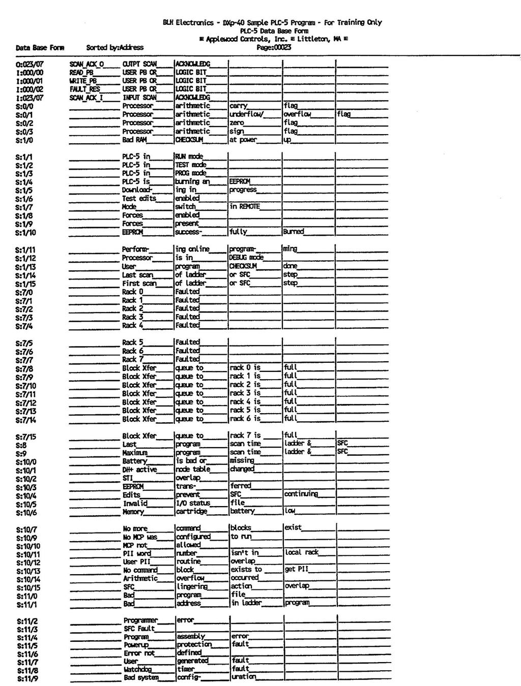
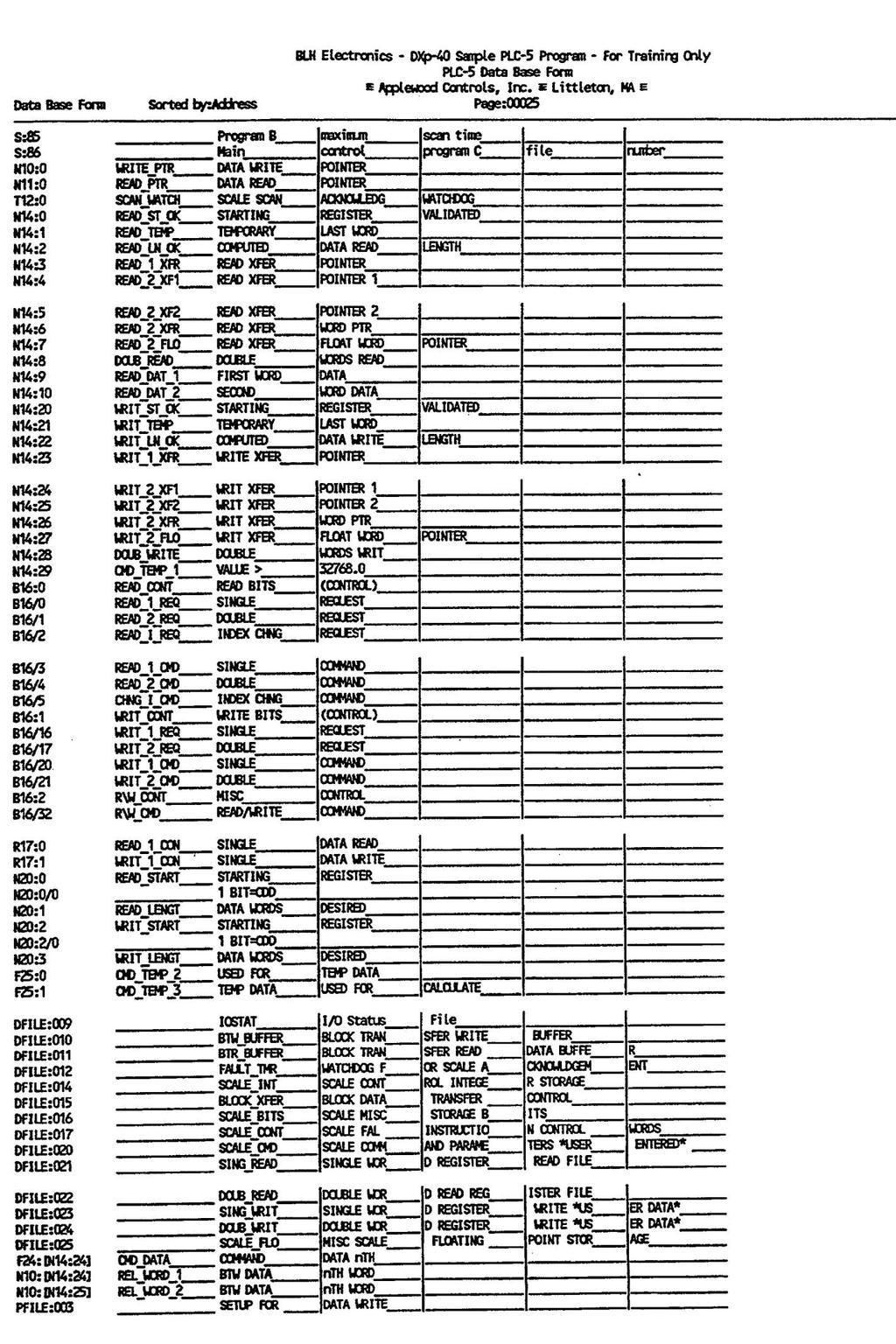
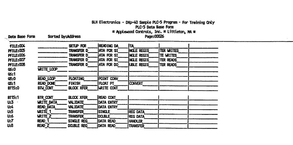
17 SECTION 4. Sample Ladder Logic Programs 4.1 INTRODUCTION This section provides several sample programs (page 4-2) that show how the Allen-Bradley PLC communicates with the DXp-40 through the RIO interface. These programs are presented as guides to simplify the development of customer PLC programs SCALE TRAINING PROGRAM The first sample program, 'MAIN PROG', begins on page 4-3 and continues to page 4-7. MAIN PROG is a scale training program designed to 'exercise' most of the RIO interface actions and responses. Each block of the program defines the function being performed and then shows individual register and bit allocations ATA READS, WRITES, AND TRANSFERS Following 'MAIN PROG' are several smaller program segments that deal with data reads, writes, and block transfers. Read, write, and block transfer programs run from page 4-8 to page These programs define both single and double register transactions REFERENCE TABLES Pages 4-23 to 4-27 provide reference tables to be used in conjunction with the sample programs. Use these tables to clarify program references. 4.2 SAMPLE PROGRAM AVAILABI LITY Sample programs are available on disk in either AB 6200 or ICOM format. Contact BLH at (781) for disk copies and/or application assistance, if needed SAMPLE PROGRAM DISCLAIMER The sample programs presented in this section were developed and tested by an authorized Allen-Bradley systems integrator for BLH. BLH makes no warranty or claim that these programs are without faults or suitable for a particular purpose. Always consult the appropriate Allen-Bradley systems programming documentation as the final authority on programming issues. 4-1
18 4-2
19 4-3
20 4-4
21 4-5
22 4-6
23 4-7
24 4-8
25 4-9
26 4-10
27 4-11
28 4-12
29 4-13
30 4-14
31 4-15
32 4-16
33 4-17
34 4-18
35 4-19
36 4-20
37 4-21
38 4-22
39 4-23
40 4-24
41 4-25
42 4-26
43 4-27
44 APPENDIX A Outline and Wiring Drawings Customer Wiring Page A-2 DXp-40 Outline Dimensions Page A-3 A-1
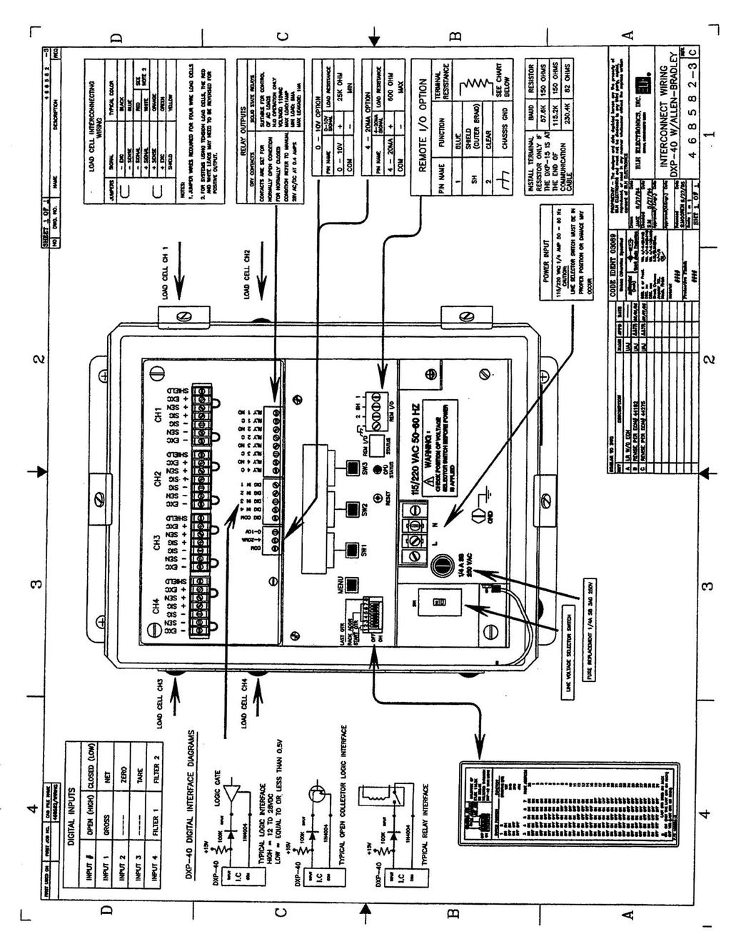
45 A-2
46 A-3
47 BLH 3 Edgewater Drive Norwood, MA U.S.A Phone (781) Fax (781)
DXP-40 FEATURES APPLICATIONS DESCRIPTION CONFIGURATION
 FEATURES Individually digitized transducer data Continuous Expert System diagnostics Dynamic digital filtering 750,000 count resolution psr channel 20 updates/sec. Multi-function set-up and calibration
DXp-10 and DXp-15 Weight Transmitter
 Precision Force and Weight Measurement Technologies DXp-10 and DXp-15 Weight Transmitter Applica pplications: Inventory Weighing Process Weighing Web Tension Measurement Product Description l Microprocessor
Safe-Weigh Process Weighing System
 FEATURES Patented synchronization techniques for digitized load cells Proactive diagnostics assure system performance Dynamic digital filtering 1 million count resolution per load cell OPTIONAL FEATURES
(Catalog Number 1747-SN) Product Data
 Product Data") (Catalog Number 1747-SN) Product Data At communication rates up to 230.4K baud, the Remote I/O Scanner provides connectivity of your SLC 500 processor to Allen-Bradley operator interface devices, drives,
(Catalog Number 1747-SN) Product Data At communication rates up to 230.4K baud, the Remote I/O Scanner provides connectivity of your SLC 500 processor to Allen-Bradley operator interface devices, drives,
Interface Module. for Allen-Bradley Remote I/O. Instruction Manual PL-533 May Rev 3.0
 Interface Module for Allen-Bradley Remote I/O Instruction Manual PL-533 May 2000 33455330 Rev 3.0 Ultrasonic level Radar At Milltronics, we endeavour to design equipment that is simple to use and reliable
SMARTLINX INTERFACE MODULE
 SMARTLINX INTERFACE MODULE FOR ALLEN-BRADLEY REMOTE I/O Instruction Manual December 2001 R Safety Guidelines Warning notices must be observed to ensure personal safety as well as that of others, and to
7561-PSD Manual Portable Battery Powered Indicator
 7561-PSD Manual Portable Battery Powered Indicator Lebow Products Inc. 1728 Maplelawn Drive P.O. Box 1089 Troy, Michigan 48084-1089 (800) 803-1164 Phone: (248) 643-0220 FAX: (248) 643-0259 Visit our web
Connecting SLC Systems as Remote I/O to PLC-5 Processors
 Reference Guide This document combines available PLC and SLC documentation to show you how you can communicate between these two types of systems over the remote I/O link. This information is in addition
Allen-Bradley. User Manual. PLC-5 Backup Communication Module (1785-BCM, 1785-BEM) product icon
 product icon") Allen-Bradley PLC-5 Backup Communication Module User Manual (1785-BCM, 1785-BEM) product icon Important User Information Because of the variety of uses for this product and because of the differences between
Allen-Bradley PLC-5 Backup Communication Module User Manual (1785-BCM, 1785-BEM) product icon Important User Information Because of the variety of uses for this product and because of the differences between
1791 Analog Block I/O Input/Output Modules User Manual
 User Manual Because of the variety of uses for the products described in this publication, those responsible for the application and use of this control equipment must satisfy themselves that all necessary
Interface Module for Allen-Bradley Remote I/O Instruction Manual PL-533 September 1999
 Interface Module for Allen-Bradley Remote I/O Instruction Manual PL-533 September 1999 33455330 Rev 2.0 Ultrasonic level Radar At Milltronics, we endeavour to design equipment that is simple to use and
CONFIGURATION GUIDE A-B REMOTE I/O LINK ADAPTOR FOR DL-KFR PC CARDS
 CONFIGURATION GUIDE A-B REMOTE I/O LINK ADAPTOR FOR DL-KFR PC CARDS This configuration guide provides programming information for the DL-PC (ISA) and DL-STD (STD 80 and 32) Remote I/O Link applications.
Model 815 User s Manual
 Model 815 User s Manual CAUTION Risk of electrical shock. Do not remove cover. No user serviceable parts inside. Refer servicing to qualified service personnel. Weigh-Tronix reserves the right to change
Remote I/O ALLEN-BRADLEY Remote I/O Interface for IQ plus 310A and IQ plus 800/810 Indicators
 Remote I/O ALLEN-BRADLEY Remote I/O Interface for IQ plus 310A and IQ plus 800/810 Indicators Version 2.04 Installation and Programming Manual 36254 Contents About This Manual... 1 1.0 Introduction...
PC 150. Digital Bench Scale. Operation Manual
 PC 150 Digital Bench Scale Operation Manual Revision 1.2 September 14, 2000 1996-2000 Transcell Technology, Inc. Contents subject to change without notice. Transcell Technology, Inc. 35 Waltz Drive Wheeling,
The Communicator. User s guide. Model 2400 Integrated wireless communication module. Page 1. Page 24
 The Communicator Model 2400 Integrated wireless communication module User s guide Control Chief Corporation 200 Williams Street Bradford PA. 16701 1.800.233.3016 95-00-0-011 Rev. C Page 24 Page 1 Table
LCp-100 Weight Indicator/Transmitter
 Precision Force and Weight Measurement Technologies LCp-100 Weight Indicator/Transmitter Process Applications: Mix Tanks Blenders Reactors Product Description Hardware Features 1 Million Count Resolution,
IQ plus 800/810. Digital Weight Indicators Version 3.1. Installation Manual
 Rice Lake IQ Plus 800 IQ Plus 810 installation Manual IQ plus 800/810 Digital Weight Indicators Version 3.1 Installation Manual 42100 Contents About this Manual... 1 1.0 Introduction... 1 1.1 Optional
Installation Instructions
 Installation Instructions 1771-SDN/B DeviceNet Scanner Module Installation Instructions 1 (Catalog Number 1771-SDN/B) Use this document as a guide to installing your 1771-SDN/B Scanner Module. Before you
Table of Contents
 Table of Contents Table of Contents Analog Input Module (12-Bit) Assembly cat. no. 1771-IF Series B and Analog Input Expander (12-Bit) cat. no. 1771-E1, -E2, -E3 are plug-in modules that interface analog
Instruction Manual March smartlinx interface module REMOTE I/O
 Instruction Manual March 2004 R smartlinx interface module REMOTE I/O Safety Guidelines Warning notices must be observed to ensure personal safety as well as that of others, and to protect the product
Loadcell. Table Of Contents. Loadcell Help Rev: 17/06/04
 Loadcell Help Rev: 17/06/04 Table Of Contents Loadcell... 1 Loadcell Quickstart... 1 FB Operations... 1 Loadcell Help Rev: 17/06/04... 2 Loadcell Quickstart... 2 FB Operations... 2 Loadcell Hardware Configuration...
A-B RIO Scanner. Table of contents
 Table of contents 1 About... 3 1.1 Overview... 3 1.1.1 Introduction...3 1.1.2 Concepts... 3 1.1.3 Features...3 1.1.4 Required Hardware/Software...4 1.1.4.1 Hardware... 4 1.1.4.2 Software... 4 1.2 Warranty...4
Rice Lake Weigh Scale Application Programmable Serial Interface Card
 Rice Lake Weigh Scale Application Programmable Serial Interface Card USER MANUAL Rev. P1.55 April, 2009 DeltaV is a trademark of Emerson Process Management, Inc Emerson Process Management, Inc. 1998, 1999.
Classic PLC 5 Programmable Controllers (1785 LT, 1785 LT2, 1785 LT3, 1785 LT4) Product Data
 Product Data") Product Data The classic PLC-5 programmable controllers are high-speed processors used for control and information processing. They are single-slot processors that mount in a 1771 I/O chassis. These processors
Product Data The classic PLC-5 programmable controllers are high-speed processors used for control and information processing. They are single-slot processors that mount in a 1771 I/O chassis. These processors
HM-1756-SGI-WM Strain Gage Input Module
 Helm Instrument Company, Inc. 361 West Dussel Drive Maumee, Ohio 43537 USA 419/ 893-4356 Fax: 419/ 893-1371 www.helminstrument.com HM-1756-SGI-WM Strain Gage Input Module User Manual Force Measurement
RSTC1000 HMI/PLC Design Guide WEB CONTROL PRODUCTS. User Manual FORM NO. L B MTY (81)
") WEB CONTROL PRODUCTS User Manual RSTC1000 HMI/PLC Design Guide DANGER Read this manual carefully before installation and operation. Follow Nexen s instructions and integrate this unit into your system
WEB CONTROL PRODUCTS User Manual RSTC1000 HMI/PLC Design Guide DANGER Read this manual carefully before installation and operation. Follow Nexen s instructions and integrate this unit into your system
SPI Protocol Interface Module Cat. No SPI Concepts Manual
 Concepts Manual Because of the variety of uses for the products described in this publication, those responsible for the application and use of this control equipment must satisfy themselves that all necessary
GSE Scale Systems A div of SPX Corporation
 GSE Scale Systems A div of SPX Corporation GSE 60-Series Instruments DeviceNet Communications Option And Application Note Ver 1.0.2 8/24/04 P/N 39-10-38883 Published by GSE Scale Systems 42860 Nine Mile
Weight Indicator. Model Intuition 22i FEATURES APPLICATIONS DESCRIPTION OPTIONS CONFIGURATION
 FEATURES Large six-digit LCD display (0.8 in, 21 mm) Built-in weighing and counting modes Alibi memory retains last 100k transactions Drives up to 10 x 350 Ω load cells (4/6 wires) or 20 700 Ω load cells
3100/3150-ROC Fisher ROC Communications Revision 1.2 March 8, 2001
 3100/3150-ROC Fisher ROC Communications Revision 1.2 March 8, 2001 USER MANUAL ProSoft Technology, Inc. 9801 Camino Media, Suite 105 Bakersfield, CA 93311 (661) 664-7208 (661) 664-7233 (fax) E-mail address:
1746 Weigh Scale Module
 Helm Instrument Company, Inc. 361 West Dussel Drive Maumee, Ohio 43537 USA 419/ 893-4356 Fax: 419/ 893-1371 www.helminstrument.com 1746 Weigh Scale Module Model HM-604-WM Instruction Manual February, 2010
AD-4401 WEIGHING INDICATOR A-IE
 AD-440 WEIGHING INDICATOR 386-2A-IE 998 A&D Company Ltd. All rights reserved. No part of this publication may be reproduced, transmitted, transcribed, or translated into any language in any form by any
Throughout this manual we use notes to make you aware of safety considerations:
 Because of the variety of uses for the products described in this publication, those responsible for the application and use of this control equipment must satisfy themselves that all necessary steps have
3100/ N2 Johnson Controls N2 Slave Interface Module Revision 1.01 USER MANUAL. January 1996 Updated April, 1998
 3100/3150 - N2 Johnson Controls N2 Slave Interface Module Revision 1.01 USER MANUAL January 1996 Updated April, 1998 ProSoft Technology, Inc. 1675 Chester Ave. Fourth Floor Bakersfield, CA 93301 prosoft@prosoft-technology.com
Communication Protocols for Common Controls - DC-2 Modbus Communications, Devicenet Gateway Communications and SPI Communications
 USER GUIDE UGD027-0804 www.conairgroup.com Communication Protocols for Common Controls - DC-2 Modbus Communications, Devicenet Gateway Communications and SPI Communications Corporate Office: 724.584.5500
TECH NOTES-311. Integrating RACO Verbatim Gateway with the Allen-Bradley CompactLogix PLC via DH485
 TECH NOTES-311 Integrating RACO Verbatim Gateway with the Allen-Bradley CompactLogix PLC via DH485 This technical note explains how to interface the RACO Verbatim Gateway system with the Allen-Bradley
TECH NOTES-307. Integrating RACO Verbatim Gateway with the Allen-Bradley SLC 5/05 Series PLC via Ethernet
 TECH NOTES-307 Integrating RACO Verbatim Gateway with the Allen-Bradley SLC 5/05 Series PLC via Ethernet This technical note explains how to interface the RACO Verbatim Gateway system with the Allen-Bradley
TECH NOTES-309. Integrating RACO Verbatim Gateway with the Allen-Bradley ControlLogix Series PLC via Ethernet
 TECH NOTES-309 Integrating RACO Verbatim Gateway with the Allen-Bradley ControlLogix Series PLC via Ethernet This technical note explains how to interface the RACO Verbatim Gateway system with the Allen-Bradley
(Cat. No L26B, -L46B, and -L86B) Supplement
 Supplement") (Cat. No. 1785-L26B, -L46B, and -L86B) Supplement Because of the variety of uses for the products described in this publication, those responsible for the application and use of this control equipment
(Cat. No. 1785-L26B, -L46B, and -L86B) Supplement Because of the variety of uses for the products described in this publication, those responsible for the application and use of this control equipment
SECTION 5 HSLRT6 WINDOWS BASED SETUP PROGRAM REFERENCE
 The Windows based set-up program is menu driven, allowing the user to easily view data, alter setup variables or set machine timing (machine offset, timing signal locations, etc.), using a PC running the
Throughout this manual we use notes to make you aware of safety considerations:
 Because of the variety of uses for the products described in this publication, those responsible for the application and use of this control equipment must satisfy themselves that all necessary steps have
LCM SYSTEMS. TR150 Portable Battery Powered Indicator. Instruction Manual. Software version V2.XX
 TR50 Portable Battery Powered Indicator Instruction Manual Software version V2.XX CONTENTS What is TEDS? Basic concept How it works Advantages Introduction User operation Electrical connection information
3100/ PCX MetOne Model PCX Master Module Revision 1.1 USER MANUAL. November 1996
 3100/3150 - PCX MetOne Model PCX Master Module Revision 1.1 USER MANUAL November 1996 ProSoft Technology, Inc. 9801 Camino Media Suite 105 Bakersfield, CA 93311 prosoft@prosoft-technology.com http://www.prosoft-technology.com
Profibus DP Expansion Board
 Profibus DP Expansion Board Catalog No. EXBD04 Installation and Operating Manual 10/02 MN1393 Table of Contents Section 1 General Information................................................... 1 1 Introduction.......................................................
Backup Scanner Module
 Backup Scanner Module (Catalog Number 747-BSN) User Manual Important User Information Because of the variety of uses for the products described in this publication, those responsible for the application
DeviceNet Expansion Board
 DeviceNet Expansion Board Catalog No. EXBD05 Installation and Operating Manual 10/02 Table of Contents Section 1 General Information................................................... 1 1 Introduction.......................................................
GEMCO. Installation & Programming Manual. Series 1746R. PLC Resolver Interface Module. For Allen-Bradley SLC 500 I/O Chassis
 Series 746R GEMCO PLC Resolver Interface Module Installation & Programming Manual For Allen-Bradley SLC 500 I/O Chassis Spec Tech Industrial 03 Vest Ave. Valley Park, MO 63088 Phone: 888 SPECTECH E-mail:
IND560. Terminal. PLC Interface Manual (05/2009).R05
.R05") IND560 Terminal PLC Interface Manual www.mt.com 72184339 (05/2009).R05 METTLER TOLEDO 2009 No part of this manual may be reproduced or transmitted in any form or by any means, electronic or mechanical,
IND560 Terminal PLC Interface Manual www.mt.com 72184339 (05/2009).R05 METTLER TOLEDO 2009 No part of this manual may be reproduced or transmitted in any form or by any means, electronic or mechanical,
TABLE OF CONTENTS INTRODUCTION. 3. Analog Input Analog Output Digital Input Digital Output OPERATIONAL DESCRIPITON.. 7 PROGRAMMING AND INITIAL SETUP.
 DIVERSIFIED HEAT TRANSFER SERIES 700 STEAM GENERATOR CONTROLLER INSTRUCTION MANUAL VISIT OUR WEBSITE AT SIGMACONTROLS.COM SERIES 700 DHT STEAM GENERATOR MANUAL 042514 2 TABLE OF CONTENTS INTRODUCTION.
Reference Manual. ACT350 Fieldbus Communication - SAI
 Reference Manual ACT350 Fieldbus Communication - SAI Contents A Standard Automation Interface... A-4 A.1. Overview... A-4 A.2. General Structure... A-5 A.2.1. Cyclic Data... A-5 A.2.2. Two Types of Cyclical
DMC-688. When Accuracy Counts
 DMC-688 Money Counti ng Scal e When Accuracy Counts Operation Manual 73360 DMC- 688 SERIES OPERATING MANUAL SECTION INDEX PAGE NUMBER 1.0. GENERAL 1.1. Unlocking Procedure 1.2. Setting Up 2 3 2.0. SPECIFICATIONS
Gateway 1400 Reference Manual
 Profibus-DP Gateway 1400 Reference Manual Copyright All Rights Reserved. No part of this document may be copied, reproduced, republished, uploaded, posted, transmitted, distributed, stored in or introduced
Modbus RTU Slave Driver is available within the following MicroLogix PLCs
 TECH NOTES-303 Integrating RACO Verbatim Gateway and Allen-Bradley MicroLogix via Modbus RTU over RS232 This technical note explains how to interface the RACO Verbatim Gateway system with the Allen-Bradley
Communication settings: Network configuration can be done via the Anybus IP configuration setup tool or via the on board Web server
 SmartLinx EtherNet/IP instruction and use APPLICATION GUIDE Objective: Show the user how to configure and use an EtherNet/IP SmartLinx communication module. AG082415 While every effort was made to verify
4110 HART Level Encoder
 4110 HART Level Encoder Precision encoding instrument for transmission of level measurement from mechanical float gauges Features Universal connection - mounts to all standard float gauges Low maintenance
805HP. Handheld Digital Weight Indicator Operations Manual (V1612) Anyload Transducer Co. Ltd Website:
 Anyload Transducer Co. Ltd Website:") 805HP Handheld Digital Weight Indicator Operations Manual (V1612) Anyload Transducer Co. Ltd Website: www.anyload.com Email: info@anyload.com TABLE OF CONTENTS 1. Introduction and Product Features 3 2.
805HP Handheld Digital Weight Indicator Operations Manual (V1612) Anyload Transducer Co. Ltd Website: www.anyload.com Email: info@anyload.com TABLE OF CONTENTS 1. Introduction and Product Features 3 2.
Power Meter PowerMonitor 500
 ROCKWELL AUTOMATION PROCUREMENT SPECIFICATION PROCUREMENT SPECIFICATION PowerMonitor 500 NOTICE: The specification guidelines in this document are intended to aid in the specification of products. Specific
LCp-104 Weighing System Operator s Manual
 BLH Nobel LCp-104 Weighing System Operator s Manual TM049 RevE 12/1/15 Doc 35116 NOTICE BLH Nobel makes no representation or warranties of any kind whatsover with respects to the contents hereof and specifically
Transmitter WST 3 From prog. name W001A100. Technical Manual
 GB Transmitter WST 3 From prog. name W001A100 Technical Manual Transmitter WST 3 Contents 1. Introduction Functions... 1-2 Technical data... 1-4 2. Installation General... 2-1 Electrical installation...
BACNet Gateway Option
 INSTRUCTION MANUAL MultiGard 5000 System Integration BACNet Gateway Option 1-800-MSA-INST or FAX (724) 776-8783 MSA International (412) 967-3354 or FAX (412) 967-3451 In Canada 1-800-267-0672 or FAX (416)
PROFIBUS Interface WM : PD
 ふ PROFIBUS Interface WM : PD4000303 This is a hazard alert mark. This mark informs you about the operation of the product. Note This manual is subject to change without notice at any time to improve the
GSE Scale Systems Ethernet IP Option
 AN SPX BRAND GSE Scale Systems Ethernet IP Option Option P/N 24660B-421C0 Revision 0.51 Apr 3, 2008 Page 1 of 27 TABLE OF CONTENTS 1. INTRODUCTION...5 1.1 Overview...5 1.2 Definiti ons...5 1.3 Reference
ID8400 Stamper Communications for Firmware Versions 5 and 6
 ID8400 Stamper Communications for Firmware Versions 5 and 6 Introduction This document will describe the Extended Protocol Communications as implemented with the ITM8400 marking system software. Extended
Digital Bench Scale. Revision 8.93 August 12, 1993
 Digital Bench Scale Revision 8.93 August 12, 1993 Salter Brecknell Weighing Products 1000 Armstrong Drive Fairmont, MN 56031 Tel (800) 637-0529 Tel (507) 238-8702 Fax (507) 238-8271 E-mail: sales@salterbrecknell.com
Hardy HI 2080 EASY 8 Quick Start & Programming Guide
 Hardy HI 2080 EASY 8 Quick Start & Programming Guide Section 1: Section 2: Section 3: Section 4: Section 5: Specifications Wiring Guide Function Block Description Using Function Blocks Running Commands
Model 500 Digital Weight Indicator
 Rev. 1.10 Serial Number: Model 500 Digital Weight Indicator USER MANUAL 1992-2000, Reliable Scale Corporation Reliable Scale Corporation 520 Moraine Road NE Calgary, Alberta, Canada Tel:1-800-419-1189
SMARTLINX INTERFACE MODULE
 SMARTLINX INTERFACE MODULE FOR DEVICE NET Instruction Manual PL-583 April 2001 R 33455830 Rev. 1.1 Safety Guidelines Warning notices must be observed to ensure personal safety as well as that of others,
805HP. Handheld Digital Weight Indicator Operations Manual (V1612) Anyload Transducer Co. Ltd Website:
 Anyload Transducer Co. Ltd Website:") 805HP Handheld Digital Weight Indicator Operations Manual (V1612) Anyload Transducer Co. Ltd Website: www.anyload.com Email: info@anyload.com TABLE OF CONTENTS 1. Introduction and Product Features 3 2.
805HP Handheld Digital Weight Indicator Operations Manual (V1612) Anyload Transducer Co. Ltd Website: www.anyload.com Email: info@anyload.com TABLE OF CONTENTS 1. Introduction and Product Features 3 2.
SCADAPack E Target 5 DF1 PLC Interface
 SCADAPack E Target 5 DF1 PLC Interface 2 Table of Contents Part I 3 1 Technical... Support 3 2 Safety... Information 4 3 Overview... 7 4 I/O Device... Interface 7 4.1 Input Devices... 9 4.2 Output Devices...
Dual Channel LVDT/RVDT Readout/Controller
 SPECIFICATIONS Large backlit dual channel display Menu driven setup and calibration 100 to 240 VAC line powered MIN, MAX, TIR, A+B and A-B functions 2.5, 3.3, 5 and 10kHz selectable excitation Analog and
ioselect Z-NET Z-SG Bridge Input Isolating I/O Module
 -wire Bridge Connection Excitation for to 30 Ω Load Cells 00 Volt (3-way) Isolation Excellent Accuracy (0.0%) DIP Switch Configuration Digital Input Tare Calibration RS8 Modbus RTU Superior Flexible Power:
Digital Bench Scale. Revision 1.2 August 24, Contents subject to change without notice.
 Digital Bench Scale Revision 1. August 4, 000 Contents subject to change without notice. Salter Brecknell Weighing Products 1000 Armstrong Drive Fairmont, MN 56031 Tel (800) 637-059 Tel (507) 38-870 Fax
PanelViewt 1200 Transfer Utility User Manual
 User Manual Solid state equipment has operational characteristics differing from those of electromechanical equipment. Safety Guidelines for the Application, Installation and Maintenance of Solid State
CTI 2550 EIGHT CHANNEL ISOLATED ANALOG INPUT MODULE INSTALLATION AND OPERATION GUIDE. Version 2.0 CTI Part # IOG $25
 CTI 2550 EIGHT CHANNEL ISOLATED ANALOG INPUT MODULE INSTALLATION AND OPERATION GUIDE Version 2.0 CTI Part #062-00102 2452IOG 092205 $25 ii CTI 2550 Installation and Operation Guide Copyright 2005 Control
Programmable Logic Controllers Micro850
 ROCKWELL AUTOMATION PROCUREMENT SPECIFICATION PROCUREMENT SPECIFICATION Micro850 NOTICE: The specification guidelines in this document are intended to aid in the specification of products. Specific installations
Network configuration can be done via the Anybus IP configuration setup tool or via the on board Web server.
 SmartLinx EtherNet/IP instruction and use Objective: Show the user how to configure and use a EtherNet/IP SmartLinx communication module. AG052813 While every effort was made to verify the following information,
APNT#1208 GP-Pro EX to Allen Bradley RIO via Gateway. Explore Newer Solutions
 Application Note #1208: GP-Pro EX to Allen Bradley RIO via Gateway Explore Newer Solutions When upgrading your existing HMI consider updating the communications to current technology. Pro-face GP-Pro EX
I-Dent Marker Communications for 186 CPU Firmware Versions 1 and 2
 I-Dent Marker Communications for 186 CPU Firmware Versions 1 and 2 Introduction This document will describe the Extended Protocol Communications as implemented with the InfoSight I-Dent marker software.
SMARTLINX INTERFACE MODULE
 SMARTLINX INTERFACE MODULE FOR DEVICE NET Instruction Manual December 2001 R Safety Guidelines Warning notices must be observed to ensure personal safety as well as that of others, and to protect the product
MYRIAD QLC 4-CHANNEL MONITOR/CONTROLLER INSTRUCTION MANUAL
 MYRIAD QLC 4-CHANNEL MONITOR/CONTROLLER INSTRUCTION MANUAL VISIT OUR WEBSITE SIGMACONTROLS.COM MYR QLC MANUAL 013114 2 TABLE OF CONTENTS INTRODUCTION 3 Ordering Information Specifications Features WIRING
AB RIO Slave TLM. Table of contents
 Table of contents 1 About... 2 1.1 Overview...2 1.1.1 Introduction...2 1.1.2 Concepts... 2 1.1.3 Features...2 1.1.4 Required Hardware/Software...2 1.1.4.1 Hardware... 2 1.1.4.2 Software... 3 1.2 Warranty...3
LCI User Manual mantracourt.com
 LCI User Manual mantracourt.com LCI Load Cell Junction Box with Fault Monitor Contents Chapter 1 Introduction to the LCI... 2 Chapter 2 Installing the LCI... 3 Chapter 3 Setting up the LCI... 4 Sequence
QC-3265 Checkweigher User s Manual
 QC-3265 Checkweigher User s Manual CAUTION Risk of electrical shock. Do not remove cover. No user serviceable parts inside. Refer servicing to qualified service personnel. Weigh-Tronix reserves the right
Using the MODBUS Protocol with Athena Series C (1ZC, 16C, 18C, and 25C) Controllers
 Controllers") Using the MODBUS Protocol with Athena Series C (1ZC, 16C, 18C, and 25C) Controllers Athena and Multi-Comm are trademarks of Athena Controls, Inc. MODBUS is a trademark of AEG Schneider Automation, Inc.
Using the MODBUS Protocol with Athena Series C (1ZC, 16C, 18C, and 25C) Controllers Athena and Multi-Comm are trademarks of Athena Controls, Inc. MODBUS is a trademark of AEG Schneider Automation, Inc.
MVS-Modbus Installation and Operation Manual
 MVS-Modbus Installation and Operation Manual CAUTION It is essential that all instructions in this manual be followed precisely to ensure proper operation of the equipment. 97-1125-01 Rev. C Dec 2002 NOTICE
Read this chapter to familiarize yourself with this manual. It tells you how to use the manual properly and efficiently.
 Table of Contents Table of Contents Read this chapter to familiarize yourself with this manual. It tells you how to use the manual properly and efficiently. This manual contains 5 chapters and 6 appendices:
SGH Cable Actuated Sensor Industrial CANOpen
 Cable Actuated Sensor Industrial CANOpen Two Available Stroke Ranges: 0-80 in & 0-120 in. Rugged Polycarbonate Enclosure Simple Installation Compact Design Built for IP67 environments IN STOCK FOR QUICK
CONTENTS CONTENTS AWS-4050 Guide
 CONTENTS 1 CONTENTS CONTENTS...1 INTRODUCTION...2 Description...2 System Specifications...2 OPERATION...3 Display Operation...3 nction...4 Back Panel Inputs...4 Transducer Input (12-pin connector)...4
Allen-Bradley PLCs. 100 Programmable Controller Processor Unit -Catalog Nos LPI01, -LP102, -LP103, -LP104 SLC TM. The Unit
 PRODUCT DATA SLC TM 100 Programmable Controller Processor Unit -Catalog Nos. 1745-LPI01, -LP102, -LP103, -LP104 The SLC 100 programmab/e Contro"er The SLC 100 Programmable Controller is easy to program,
Hardy EASY 8 Quick Start & Programming Guide. Function Block Description
 Hardy EASY 8 Quick Start & Programming Guide Section 1: Section 2: Section 3: Wiring Guide Function Block Description Using Function Blocks Section 1: Wiring Guide 1 Excitation + 7 C2+ (PLUS version only)
A0-10 ANALOG OUTPUT. Instruction Manual April 2001 NALOG OUTPUT
 A0-10 ANALOG OUTPUT Instruction Manual April 2001 NALOG OUTPUT Safety Guidelines Warning notices must be observed to ensure personal safety as well as that of others, and to protect the product and the
805HP. Handheld Digital Weight Indicator User s Manual (v1703) Anyload Transducer Co. Ltd Website:
 Anyload Transducer Co. Ltd Website:") 805HP Handheld Digital Weight Indicator User s Manual (v1703) Anyload Transducer Co. Ltd Website: www.anyload.com Email: info@anyload.com TABLE OF CONTENTS 1. Introductions and Features 2 2. Safety Recommendations
805HP Handheld Digital Weight Indicator User s Manual (v1703) Anyload Transducer Co. Ltd Website: www.anyload.com Email: info@anyload.com TABLE OF CONTENTS 1. Introductions and Features 2 2. Safety Recommendations
DL3500-DH+/MODBUS COMMUNICATION CONTROLLER APPLICATION NOTE
 DL3500-DH+/MODBUS COMMUNICATION CONTROLLER APPLICATION NOTE This application note contains information on the DL3500-Modbus to DH+ interface. The DL3500 model contains two modes of operation, Modbus Master
Division Services. Model: DPAS-300. Division Portable Bulk Load Accumulator Scale INDUSTRIAL PH (901) FAX (901)
 FAX (901)") Division Services 5680 E. Shelby Drive Memphis, TN 38141 PH (901) 366-4220 FAX (901) 365-3934 Model: DPAS-300 VERSION 5 Division Portable Bulk Load Accumulator Scale INDUSTRIAL Division Model DPAS-300
Division Services 5680 E. Shelby Drive Memphis, TN 38141 PH (901) 366-4220 FAX (901) 365-3934 Model: DPAS-300 VERSION 5 Division Portable Bulk Load Accumulator Scale INDUSTRIAL Division Model DPAS-300
AiRanger DPL Plus. Dual-Point Ultrasonic Level Measurement System
 AiRanger DPL Plus Dual-Point Ultrasonic Level Measurement System Part 1. General 1.1 Scope A. This section describes the requirements for an ultrasonic dual-point level scanner controller with transceiver
2XX-MODBUSTCP. ModbusTCP/IP Interface Card For 200 Series Indicators (205, 210 and 215) INSTALLATION MANUAL
 INSTALLATION MANUAL") 2XX-MODBUSTCP ModbusTCP/IP Interface Card For 200 Series Indicators (205, 210 and 215) INSTALLATION MANUAL 8200-M571-O1 Rev A PO BOX 151 WEBB CITY, MO 64870 Printed in USA 01/10 PH (417) 673-4631 FAX (417)
2XX-MODBUSTCP ModbusTCP/IP Interface Card For 200 Series Indicators (205, 210 and 215) INSTALLATION MANUAL 8200-M571-O1 Rev A PO BOX 151 WEBB CITY, MO 64870 Printed in USA 01/10 PH (417) 673-4631 FAX (417)
Automationdirect.com. D i r e c t L o g i c M a g n e t i c P u l s e I n p u t C o p r o c e s s o r F 4-8 M P I
 Automationdirect.com D i r e c t L o g i c 0 5 M a g n e t i c P u l s e I n p u t C o p r o c e s s o r F - 8 M P I Manual Order Number: F-8MPI-M TRADEMARKS AutomationDirect.com is a Trademark of Automationdirect.com
DNETEXT-C CAN Bus Extender, Version 3 User s Manual. Brad Harrison
 DNETEXT-C CAN Bus Extender, Version 3 User s Manual Brad Harrison Although every effort has been made to insure the accuracy of this document, all information is subject to change without notice. Woodhead
SERIES CMT CARBON MONOXIDE GAS TRANSMITTER
 SERIES CMT CARBON MONOXIDE GAS TRANSMITTER INSTALLATION OPERATION AND MAINTENANCE MANUAL DWYER INTRUMENTS, INC. PO BOX 373, MICHIGAN CITY, IN. 46360 USA PHONE: 800-872-9141 FAX: 219-872-9057 Web: www.dwyer-inst.com