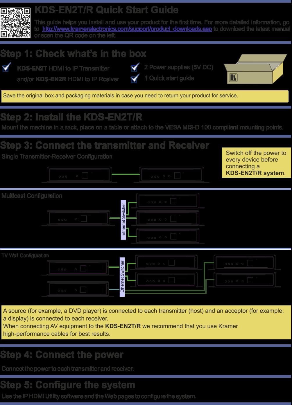
KRAMER ELECTRONICS LTD. USER MANUAL MODELS: KDS-EN2T HDMI to IP Transmitter. KDS-EN2R HDMI to IP Receiver. P/N: Rev 2
|
|
|
- Spencer Cain
- 6 years ago
- Views:
Transcription
1 KRAMER ELECTRONICS LTD. USER MANUAL MODELS: KDS-EN2T HDMI to IP Transmitter KDS-EN2R HDMI to IP Receiver P/N: Rev 2

2
3 21 Contents 1 Introduction 1 2 Getting Started Achieving the Best Performance Safety Instructions Recycling Kramer Products 3 3 Overview Using the Cables 5 4 Defining the KDS-EN2T and KDS-EN2R The KDS-EN2T HDMI to IP Transmitter Your KDS-EN2R Underside of the KDS-EN2T/KDS-EN2R Setting the Multicast Group ID 10 5 Connecting the KDS-EN2T/KDS-EN2R KDS-EN2T/KDS-EN2R Transmitter Receiver Setup Multicasting Setup Video Wall Setup Connecting to the KDS-EN2T and KDS-EN2R via RS Configuring the System Bonjour Service IP HDMI Utility Configuring a TV Wall Setup The Web Pages 27 7 Technical Specifications 30 Figures UFigure 1: KDS-EN2T HDMI to IP TransmitterU 6 UFigure 2: KDS-EN2RU 7 UFigure 3: KDS-EN2R UndersideU 8 UFigure 4: Connecting the HDMI to IP Transmitter and Receiver SystemU 12 UFigure 5: Multicasting ApplicationU 14 UFigure 6: Connecting the RS-232 Y-cableU 16 UFigure 7: Video Wall ApplicationU 17 UFigure 8: IP-HDMI Utility Main WindowU 20 UFigure 9: Devices Discovered on the NetworkU 20 UFigure 10: Check the Devices Discovered on the Network U UFigure 11: The Get Information WindowU 21 UFigure 12: Apply RS-232 and Group ID settingsu 22 UFigure 13: System RebootingU 22 UFigure 14: TV Wall Setup Choosing Wall SizeU 23 UFigure 15: TV Wall Setup Setting the Wall Size to 3x3U 24 UFigure 16: TV Wall Setup Setting the Position of each DisplayU 24 UFigure 17: TV Wall Setup Setting the Bezel and Gap CompensationU 25 UFigure 18: Advanced Setup Selecting a device to Fine TuneU 25 UFigure 19: Advanced Setup Fine Tune a deviceu 26 UFigure 20: Web Page Version Information WindowU 28 UFigure 21: Web Page Firmware Update WindowU 28 UFigure 22: Web Page Basic Setup WindowU 29 KDS-EN2T, KDS-EN2R Contents i
4 1 Introduction Welcome to Kramer Electronics! Since 1981, Kramer Electronics has been providing a world of unique, creative, and affordable solutions to the vast range of problems that confront video, audio, presentation, and broadcasting professionals on a daily basis. In recent years, we have redesigned and upgraded most of our line, making the best even better! Our 1,000-plus different models now appear in 11 groups that are clearly defined by function: GROUP 1: Distribution Amplifiers; GROUP 2: Switchers and Routers; GROUP 3: Control Systems; GROUP 4: Format/Standards Converters; GROUP 5: Range Extenders and Repeaters; GROUP 6: Specialty AV Products; GROUP 7: Scan Converters and Scalers; GROUP 8: Cables and Connectors; GROUP 9: Room Connectivity; GROUP 10: Accessories and Rack Adapters and GROUP 11: Sierra Video Products. Thank you for purchasing the Kramer DigiTOOLS KDS-EN2T HDMI to IP Transmitter and/or KDS-EN2R (sold separately), which are ideal for: Digital signage, retail centers and leisure facilities Transportation hubs, educational facilities and corporate environments KDS-EN2T, KDS-EN2R - Introduction 1
5 2 Getting Started We recommend that you: Unpack the equipment carefully and save the original box and packaging materials for possible future shipment Review the contents of this user manual i Go to to check for up-to-date user manuals, application programs, and to check if firmware upgrades are available (where appropriate). 2.1 Achieving the Best Performance To achieve the best performance: Use only good quality connection cables (we recommend Kramer highperformance, high-resolution cables) to avoid interference, deterioration in signal quality due to poor matching, and elevated noise levels (often associated with low quality cables) Do not secure the cables in tight bundles or roll the slack into tight coils Avoid interference from neighboring electrical appliances that may adversely influence signal quality Position your Kramer KDS-EN2T/KDS-EN2R away from moisture, excessive sunlight and dust It is recommended to operate the system on a dedicated Gigabit Ethernet network, not to be combined with other network traffic or with access to the Internet! This equipment is to be used only inside a building. It may only be connected to other equipment that is installed inside a building. 2 KDS-EN2T, KDS-EN2R - Getting Started
6 2.2 Safety Instructions! Caution: Warning: There are no operator serviceable parts inside the unit Use only the Kramer Electronics input power wall adapter that is provided with the unit Warning: Disconnect the power and unplug the unit from the wall before installing 2.3 Recycling Kramer Products The Waste Electrical and Electronic Equipment (WEEE) Directive 2002/96/EC aims to reduce the amount of WEEE sent for disposal to landfill or incineration by requiring it to be collected and recycled. To comply with the WEEE Directive, Kramer Electronics has made arrangements with the European Advanced Recycling Network (EARN) and will cover any costs of treatment, recycling and recovery of waste Kramer Electronics branded equipment on arrival at the EARN facility. For details of Kramer s recycling arrangements in your particular country go to our recycling pages at KDS-EN2T, KDS-EN2R - Getting Started 3
7 3 Overview The Kramer KDS-EN2T and KDS-EN2R are an IP transmitter (host) and receiver (client) system for HDMI and bidirectional RS-232 signals. The KDS-EN2T encodes the input signals to an IP stream and the KDS-EN2R decodes it back to HDMI and RS-232 signals. The host-client system lets you stream HD content simultaneously to one or more HDMI acceptors. The Kramer KDS-EN2T and KDS-EN2R can be used to distribute Full-HD digital content from multiple sources to more than 200 remote displays on a LAN without distance limitations from the 1080p source devices, while sustaining picture and sound quality. In addition, the KDS-EN2T/KDS-EN2R features: Flexible and scalable HDMI 1080p video broadcasting with Gigabit Ethernet LAN and no distance limitations JPEG 2000 compression technology to send a visually lossless HD image and digital audio over IP Point to point, Multicasting and broadcasting architecture, with limited bandwidth load (each channel requires about 55Mbps) Up to nine transmitters and 81 receivers that can be included in a video wall system HDMI signal transmissions over one CAT 5e, CAT 6 or CAT 7 cable Group ID setup via DIP-switches or PC application Bidirectional RS-232 Control Pass-through to control HDMI display from the host (transmitter) side Multicasting groups with Gigabit Ethernet switch (requires IEEE 802.1Q VLAN and IGMP functions) System setup via the IP-HDMI PC application and the Web pages A compact DigiTOOLS enclosure with a built-in mounting plate for versatile installation 4 KDS-EN2T, KDS-EN2R - Overview
8 i Note that the KDS-EN2T/KDS-EN2R is not HDCP compliant and will not stream HDCP encrypted content and the screen will appear black. 3.1 Using the Cables This product uses standard Ethernet cables (CAT 5/6/7). We recommend that you use Kramer high quality Twisted Pair cables. KDS-EN2T, KDS-EN2R - Overview 5
9 4 Defining the KDS-EN2T and KDS-EN2R This section defines the KDS-EN2T HDMI to IP Transmitter (see Section 4.1) and KDS-EN2R (see Section 4.2). Section 4.3 defines the underside of both the KDS- EN2T and KDS-EN2R. 4.1 The KDS-EN2T HDMI to IP Transmitter Figure 1 defines the KDS-EN2T: Figure 1: KDS-EN2T HDMI to IP Transmitter # Feature Function 1 ON LED Lights green when the power is ON and the system is active Blinks when the power is ON and the system is booting 2 LINK LED Lights green to indicate that a link is established 3 DATA LED Lights green when system is active Blinks when connecting to the receiver or if the HDMI source is disconnected 4 MODE Button Press the button using a small screwdriver (see Section 4.3) 5 6 GROUP ID DIP-switches Set the group ID (see Section 4.4) 5VDC Output BNC Connector +5V DC connector for powering the unit 7 LAN RJ-45 Connector Connects to the LAN RJ-45 connector on the KDS-EN2R directly or via an Ethernet switch 8 HDMI IN Connector Connects to an HDMI source 9 RS pin D-sub Connector Connects to an RS-232 port 6 KDS-EN2T, KDS-EN2R - Defining the KDS-EN2T and KDS-EN2R
10 4.2 Your KDS-EN2R Figure 2 defines the KDS-EN2R: Figure 2: KDS-EN2R # Feature Function 1 ON LED Lights green when the power is ON and the system is active Blinks when the power is ON and the system is booting 2 LINK LED Lights green when LAN is connected 3 DATA LED Lights green when system is active Blinks when connecting to the transmitter or if the HDMI source is disconnected 4 MODE Button Press the MODE button using a small screwdriver (see Section 4.3) EDID Button Press the EDID button using a small screwdriver (see Section 4.3) GROUP ID DIP-switches Set the group ID (see Section 4.4) 5V DC +5V DC connector for powering the unit 8 LAN RJ-45 Connector Connects to the LAN RJ-45 connector on the KDS-EN2T directly or via an Ethernet switch 9 HDMI OUT Connector Connects to the HDMI acceptor 10 RS pin D-sub Connector Connects to an RS-232 port KDS-EN2T, KDS-EN2R - Defining the KDS-EN2T and KDS-EN2R 7
11 4.3 Underside of the KDS-EN2T/KDS-EN2R The underside of both the KDS-EN2T and KDS-EN2R defines the button functionality, as illustrated in Figure 3: Figure 3: KDS-EN2R Underside Press Duration KDS-EN2T KDS-EN2R MODE Button MODE Button EDID Button Short N/A N/A Video/graphic mode (see Section 4.3.1) 3 seconds N/A Column position Anti Dither Press to change the 1bit/2bit/Off (see column position of the Section 4.3.2) unit when in the OSD 6 to 8 seconds on boot POWER and LINK LEDs blink Reset to factory default + FW update (see Section Reset to factory default + F/W update (see ) ) Section Update EDID (see Section 4.3.3) 8 KDS-EN2T, KDS-EN2R - Defining the KDS-EN2T and KDS-EN2R
12 4.3.1 Video/Graphic Mode Press the EDID button on the KDS-EN2R to toggle between the Video mode and the Graphic mode. The selection is immediately saved to flash memory and is saved to the non-volatile memory after rebooting the unit. In the: Video Mode, the FW automatically trades off the bandwidth with higher video quality to ensure a smooth video playing experience Graphic Mode, the FW fixes the trade-off to ensure the best possible graphic/text viewing experience Anti Dither Press and hold (for 3 sec) the EDID button on the KDS-EN2R to cycle between the anti-dithering modes (1 bit, 2 bit or Off). Dithering introduces random noise to the signal that creates a half-tone effect so that the output image appears smoother. Dithering creates a problem for low bandwidth video compression even for a static source display. To overcome the dithering problem, set the anti dither (EDID) button to 1bit or 2 bit. Set to Off if the source content does not generate a dithered output Update EDID The KDS-EN2T is shipped with a factory default EDID. We recommend updating this EDID to that of the acceptor connected to the KDS-EN2R. This EDID update ensures optimum performance according to the output resolution of the connected HDMI acceptor. To manually update the EDID: 1. Connect the new HDMI acceptor to the KDS-EN2R. 2. Press and hold the EDID button (for about 6 to 8 sec) on the KDS-EN2R to update the EDID. The EDID is updated and stored on the KDS-EN2T. i Note that in a multicast setup (see Section 5.2) it is important to update the EDID while the HDMI acceptor with the lowest resolution is connected. Once the update is complete, this EDID information will be saved to the non-volatile memory of the KDS-EN2T. KDS-EN2T, KDS-EN2R - Defining the KDS-EN2T and KDS-EN2R 9
13 4.3.4 Reset to Factory Default + FW Update Press and hold (for 6 to 8 sec) the MODE button on the KDS-EN2T/KDS-EN2R to reset to the factory default and upgrade the firmware. You can upgrade the firmware via the Web Pages or the IP HDMI Utility program (see Section ). Firmware update file name will be: Transmitter: webfwh.bin; Receiver: webfwc.bin 4.4 Setting the Multicast Group ID When hosts and clients are assigned the same multicast group ID number, all the clients in the group will decode the stream from the same host. You can set up to 16 groups either via the GROUP ID DIP-switches or the IP-HDMI Utility software (see Section 6.2). For example, to set the group ID to 1, you have to set DIP 1, 2 and 3 to OFF and DIP 4 to ON. i The application software group ID setup overrides the DIP-switch group ID setup. 10 KDS-EN2T, KDS-EN2R - Defining the KDS-EN2T and KDS-EN2R
14 5 Connecting the KDS-EN2T/KDS-EN2R You can set the KDS-EN2T/KDS-EN2R units in various configurations. For example: A single transmitter/receiver setup (see Section 5.1) A Multicasting setup (see Section 5.2) A video wall setup (see Section 5.3) 5.1 KDS-EN2T/KDS-EN2R Transmitter Receiver Setup You can use the KDS-EN2T HDMI to IP Transmitter (see Section 4.1) and the KDS-EN2R to configure an HDMI-to-IP Transmitter and Receiver system (see Figure 4). i Always switch off the power to each device before connecting it to your KDS-EN2T/KDS-EN2R. After connecting your KDS-EN2T/KDS-EN2R, connect its power and then switch on the power to each device. To connect the HDMI-to-IP transmitter and receiver system as shown in the example in Figure 4, do the following: 1. On the KDS-EN2T, connect an HDMI source (for example, the HDMI output from a media player) to the HDMI IN connector. 2. On the KDS-EN2R, connect the HDMI OUT connector to an HDMI acceptor (for example, a projector). 3. Connect the LAN RJ-45 connector on the KDS-EN2T to the LAN RJ-45 connector on the KDS-EN2R using an Ethernet cable. 4. On both the KDS-EN2T and the KDS-EN2R, connect the 5V DC power adapter to the power socket and connect the adapter to the mains electricity (not shown in Figure 4). 5. If required, connect a PC and/or controller to the RS pin D-sub Connector (see Section 5.4) to control the HDMI acceptor, for example. KDS-EN2T, KDS-EN2R - Connecting the KDS-EN2T/KDS-EN2R 11

15 Figure 4: Connecting the HDMI to IP Transmitter and Receiver System 12 KDS-EN2T, KDS-EN2R - Connecting the KDS-EN2T/KDS-EN2R
16 5.2 Multicasting Setup In the multicasting setup, one host (transmitter) and multiple clients (receivers) share the same group ID (see Section 4.4 and Section 6.2), so that all of the clients decode the same stream (encoded by the host), without creating additional load on the network. The multicast addresses used range from XXX to XXX, where XXX stands for the group ID as set by the DIP switch (see Section 4.4). The example illustrated in Figure 5 shows a multicast setup including one host connected to several clients sharing the same group ID. The host transmits the HDMI and RS-232 content to all the clients that share its group ID; other clients that are connected to the same Ethernet switch will not receive this content. Other hosts, with different group IDs can co-exist in the system (for example, a video wall setup, see Section 5.3). KDS-EN2T, KDS-EN2R - Connecting the KDS-EN2T/KDS-EN2R 13

17 Figure 5: Multicasting Application An additional KDS-EN2T host can be connected to the Ethernet switch and set to group ID 4. This host can transmit HDMI and RS-232 content to KDS-EN2R clients that are also set to group ID KDS-EN2T, KDS-EN2R - Connecting the KDS-EN2T/KDS-EN2R
18 5.3 Video Wall Setup A video wall consists of several screens that are tiled together to form one very large display. The video wall configuration consists of one or more transmitters that connect to a series of receivers that make up the video wall. Each display is connected to the output of one receiver. Usually a video wall setup would include several transmitters (one dedicated transmitter per row). Using a single transmitter for a video wall will usually result in lower video quality and tearing. The KDS-EN2T and KDS-EN2R units are each defined by their location in the video wall layout. Each KDS-EN2T is assigned a row number and defined by row number and position in the row. The position definition is unique and is usually defined once during the basic setup. To simplify the video wall configuration process, the first host of the first row of the video wall is assigned to be the control portal. The control portal controls the other transmitters and receivers in the setup via the RS-232 closed loop chain (see Figure 6). The RS-232 chain lets transmitters communicate with each other even if they are not part of the same LAN. To configure a video wall (for example, a 3x3 video wall), do the following: 1. Connect an HDMI source (for example, a media player) to the INPUT of a distribution amplifier (for example, the Kramer VM-4Hxl, 1:4 HDMI Distribution Amplifier). 2. On the distribution amplifier, connect the outputs (for example, three outputs on the Kramer VM-4Hxl) to the HDMI IN connectors of three KDS-EN2T units, respectively. 3. Connect the LAN RJ-45 connector on each KDS-EN2T unit to the input RJ-45 connector on an Ethernet switch. 4. Connect the output RJ-45 connectors on the Ethernet switch to nine KDS-EN2R units (each KDS-EN2T unit connected to the Ethernet Switch, distributes the signal to three KDS-EN2R units). KDS-EN2T, KDS-EN2R - Connecting the KDS-EN2T/KDS-EN2R 15
19 5. Connect the 9-pin D-sub Y-cable to the three KDS-EN2T units, as illustrated in Figure 6. Figure 6: Connecting the RS-232 Y-cable 6. Set the group ID via the DIP-switches. For example, set the group ID of the: KDS-EN2T transmitting to the first row and the receivers positioned in the first row to 1 KDS-EN2T transmitting to the second row and the receivers positioned in the second row to 2 KDS-EN2T transmitting to the third row and the receivers positioned in the third row to 3 7. If required, on each unit connect the 5V DC power adapter to the power socket and connect the adapter to the mains electricity (not shown in Figure 7) 8. Set the wall application for each unit via the IP HDMI Utility software and/or Web pages (see Section 6). 9. Reboot all devices. Ensure that all remote displays and all network cables are connected correctly (a video source is required at this step). 16 KDS-EN2T, KDS-EN2R - Connecting the KDS-EN2T/KDS-EN2R

20 Figure 7: Video Wall Application KDS-EN2T, KDS-EN2R - Connecting the KDS-EN2T/KDS-EN2R 17
21 5.4 Connecting to the KDS-EN2T and KDS-EN2R via RS-232 The RS-232 port can be used to: Control a peripheral machine in the transmitter receiver setup (when KDS-EN2T is connected directly to one KDS-EN2R), see Section 5.1 or the multicast setup, see Section 5.2 Chain KDS-EN2T hosts in a video wall setup, see Section KDS-EN2T, KDS-EN2R - Connecting the KDS-EN2T/KDS-EN2R
22 6 Configuring the System To configure the system you need to: Download the IP HDMI utility from our Website at Have the Bonjour service installed and running To be able to access the machine, configure the control PC s network setting to use a xxx.xxx IP domain with network mask Bonjour Service The Bonjour service automatically discovers the IP numbers assigned to the hosts and clients in your system. i 6.2 IP HDMI Utility Bonjour service lets you discover devices connected to the network and needs to be installed on your PC before installing the IP HDMI Utility for configuring the system. If your PC does not have Bonjour SDK installed, you can download it from the Apple Web site and then install it. Use the IP HDMI Utility or Web page/vw to configure the connected devices in the setup. Once downloaded, follow installation instructions. After installation is complete, double click the icon on your desktop. The following window appears: KDS-EN2T, KDS-EN2R - Configuring the System 19
23 Figure 8: IP-HDMI Utility Main Window To configure the devices: 1. Click the Search Device button. The software searches the network and the connected units are discovered: Figure 9: Devices Discovered on the Network 20 KDS-EN2T, KDS-EN2R - Configuring the System

24 Figure 9 shows two devices discovered on the network, one KDS-EN2T host and one KDS-EN2R client. 2. Check the box next to the discovered unit(s). Figure 10: Check the Devices Discovered on the Network 3. Click the Get Information button. The following window appears: Figure 11: The Get Information Window The Information window reveals the IP addresses of the selected devices, their baud rate and Group ID. KDS-EN2T, KDS-EN2R - Configuring the System 21

, in the main window, set the group ID number and click Apply: Figure 12: Apply RS-232 and Group ID settings The following window appears: Figure 13: System Rebooting If you are setting up a")
25 i In the example in Figure 11, one device is identified as the KDS-EN2R receiver (the client) and the other device is the host. The devices can be identified via their OSD which displays the IP number. This is very useful in a setup that includes multiple devices. 4. If required, in the main window set the RS-232 baud rate and click Apply. The default baud rate is set to N-1 5. If required (see Section 5.2), in the main window, set the group ID number and click Apply: Figure 12: Apply RS-232 and Group ID settings The following window appears: Figure 13: System Rebooting If you are setting up a multicasting system or a single one-to-one system the configuration is complete. To configure a TV Wall, continue to Section KDS-EN2T, KDS-EN2R - Configuring the System
.")
26 6.3 Configuring a TV Wall Setup To configure the TV Wall, check the transmitter device (client) for which you want to perform the setup. In the Main window click the TV Wall button to configure the TV wall. The software directs you to the device s basic setup Web page. The setup is simple and includes three basic steps (see Figure 14). i Note that at any time you can enter the Web page directly by typing the IP number or the device name in the browser address bar. The following example shows how to configure a 3x3 TV wall: 1. Set a 3x3 TV Wall using three KDS-EN2T hosts and nine KDS-EN2R clients as illustrated in Figure Connect the video source and reboot the devices. 3. Configure the control PC s network setting to use xxx.xxx IP domain with network mask Click the TV Wall button in the IP HDMI utility. The software enters the Web pages. 5. Click the Basic Setup tab. Step 1 in the basic setup appears (see Figure 14) Figure 14: TV Wall Setup Choosing Wall Size KDS-EN2T, KDS-EN2R - Configuring the System 23

27 6. Set the actual TV wall size (3x3 in this example). Figure 15: TV Wall Setup Setting the Wall Size to 3x3 7. Click Apply. If there is no response, check cable connections. 8. In step 2 set the position of each display in the TV wall array, defining the column and row position of each display: Figure 16: TV Wall Setup Setting the Position of each Display 9. In step 3, set the Bezel and Gap Compensation. If this is not required set the values to KDS-EN2T, KDS-EN2R - Configuring the System

.")
28 Figure 17: TV Wall Setup Setting the Bezel and Gap Compensation Once the 3 steps of Basic Setup are complete, the basic video wall configuration is ready The Advanced Setup Tab The advanced setup tab lets you fine-tune the basic setup after it is completed and can also be accessed directly via the Web pages (see Section 6.4). In step 1 you can select the device that you want to fine tune (see Figure 18) when in step 2. Figure 18: Advanced Setup Selecting a device to Fine Tune KDS-EN2T, KDS-EN2R - Configuring the System 25
29 After selecting the device (in step 1), go to step 2 to set the control options for that selected device (see Figure 19 and the following table). Figure 19: Advanced Setup Fine Tune a device 26 KDS-EN2T, KDS-EN2R - Configuring the System
30 Feature Reset to Basic Setup Screen Layout (Row x Column) Row Position Column Position Horizontal Shift Vertical Shift Horizontal Scale Up Vertical Scale Up Tearing Delay Console API Command: Function Reset the selected device to the basic setup parameters Change the array layout Change the row position of the selected device Change the column position of the selected device Shift the horizontal position of the selected client device (each step moves the image by 8 pixels) Note that you cannot shift the image to the right on the displays positioned at the left edge of the video wall, thus creating a black stripe at the video wall left edge. The same applies to shifting the image at the right edge of the video wall to the left. Shift the vertical position of the selected device (each step moves the client image by 8 pixels and the host by 1 pixel) Note that you cannot shift the image downwards on the displays positioned at the top edge of the video wall, thus creating a black stripe at the video wall top edge. The same applies to shifting the image at the lower edge of the video wall upwards. Scale up the selected client horizontally Scale up the selected client vertically Use under single host mode only to avoid tearing (in micro seconds) Typical value is 10,000 to 16,000 Enter advanced configuration commands 6.4 The Web Pages The Web pages can be accessed via the IP HDMI utility for configuring the basic setup and other functions or directly by entering the IP number or the device name to the browser address to fine tune the basic setup or to upgrade the firmware. The Web pages include two tabs, the System tab (see Section 6.4.1) and the Video Wall Setup tab (see Section 6.4.2) The System Tab Includes the version information, firmware update and utilities. KDS-EN2T, KDS-EN2R - Configuring the System 27
 and webfwc.bin for the receiver (client).")

31 Version Information Figure 20 shows the Version Information: Figure 20: Web Page Version Information Window Update Firmware The Firmware update page (see Figure 21) lets you enter the firmware update files: webfwh.bin for the transmitter (host) and webfwc.bin for the receiver (client). i Note that you have to disconnect the unit from the system before you update the firmware. Figure 21: Web Page Firmware Update Window After uploading the file follow the instructions on the screen. 28 KDS-EN2T, KDS-EN2R - Configuring the System

32 Utilities Lets you enter advanced configuration commands The Video Wall Setup Tab The Video Wall Setup lets you modify the basic configuration settings The Basic Setup The basic setup lets you set the bezel and gap compensation in 0.1mm units, as well as the wall size and the position layout, see Figure 22: Figure 22: Web Page Basic Setup Window The Advanced Setup See Section KDS-EN2T, KDS-EN2R - Configuring the System 29
33 7 Technical Specifications KDS-EN2T KDS-EN2R INPUT: 1 HDMI connector 1 LAN connector OUTPUT: 1 LAN connector 1 HDMI connector PORTS: MAX. RESOLUTION: STANDARDS COMPLIANCE: Ethernet, RS p HDMI POWER SOURCE: 5V DC, 900mA 5V DC, 650mA OPERATING TEMPERATURE: STORAGE TEMPERATURE: HUMIDITY: DIMENSIONS: WEIGHT: ACCESSORIES: 0 to +40 C (32 to 104 F) -40 to +70 C (-40 to 158 F) 10% to 90%, RHL non-condensing 12.1cm x 9.0cm x 2.8cm (4.7" x 3.5" x 1.1"), W, D, H 0.8kg (1.76lbs) approx. Power supply, RS-232 cable Power supply Specifications are subject to change without notice at 30 KDS-EN2T, KDS-EN2R - Technical Specifications

34


35 For the latest information on our products and a list of Kramer distributors, visit our Web site where updates to this user manual may be found. We welcome your questions, comments, and feedback. Web site: info@kramerel.com! SAFETY WARNING Disconnect the unit from the power supply before opening and servicing P/N: Rev: 2
USER MANUAL. VM-2Hxl 1:2 HDMI Distributor MODEL: P/N: Rev 3
 KRAMER ELECTRONICS LTD. USER MANUAL MODEL: VM-2Hxl 1:2 HDMI Distributor P/N: 2900-000672 Rev 3 Contents 1 Introduction 1 2 Getting Started 2 2.1 Achieving the Best Performance 2 2.2 Safety Instructions
KRAMER ELECTRONICS LTD. USER MANUAL MODEL: VA-1VGAN EDID Capture. P/N: Rev 2
 KRAMER ELECTRONICS LTD. USER MANUAL MODEL: VA-1VGAN EDID Capture P/N: 2900-000513 Rev 2 Contents 1 Introduction 1 2 Getting Started 2 2.1 Achieving the Best Performance 2 2.2 Recycling Kramer Products
USER MANUAL. VM-2HDCPxl 1:2 DVI Distributor MODEL: P/N: Rev 3
 KRAMER ELECTRONICS LTD. USER MANUAL MODEL: VM-2HDCPxl 1:2 DVI Distributor P/N: 2900-000510 Rev 3 Contents 1 Introduction 1 2 Getting Started 2 2.1 Achieving the Best Performance 2 2.2 Safety Instructions
USER MANUAL. PT-1C EDID Processor MODEL: P/N: Rev 3
 KRAMER ELECTRONICS LTD. USER MANUAL MODEL: PT-1C EDID Processor P/N: 2900-300276 Rev 3 Contents 1 Introduction 1 2 Getting Started 2 2.1 Achieving the Best Performance 2 2.2 Recycling Kramer Products
USER MANUAL. 671T DVI Optical Transmitter. 671R DVI Optical Receiver MODEL: P/N: Rev 4
 KRAMER ELECTRONICS LTD. USER MANUAL MODEL: 671T DVI Optical Transmitter 671R DVI Optical Receiver P/N: 2900-000484 Rev 4 Contents 1 Introduction 1 2 Getting Started 2 2.1 Achieving the Best Performance
KRAMER ELECTRONICS LTD. USER MANUAL MODEL: VS-41HC 4x1 HDMI Switcher. P/N: Rev 4
 KRAMER ELECTRONICS LTD. USER MANUAL MODEL: VS-41HC 4x1 HDMI Switcher P/N: 2900-000423 Rev 4 Contents 1 Introduction 1 2 Getting Started 2 2.1 Achieving the Best Performance 2 2.2 Safety Instructions 3
USER MANUAL. VA-1USB-T USB Transmitter. VA-1USB-R USB Receiver MODELS: P/N: Rev 3
 KRAMER ELECTRONICS LTD. USER MANUAL MODELS: VA-1USB-T USB Transmitter VA-1USB-R USB Receiver P/N: 2900-300209 Rev 3 Contents 1 Introduction 1 2 Getting Started 2 2.1 Achieving the Best Performance 2 2.2
USER MANUAL. PT-101UHD HDMI Repeater MODEL: P/N: Rev 3.
 USER MANUAL MODEL: PT-101UHD HDMI Repeater P/N: 2900-300492 Rev 3 www.kramerav.com Contents 1 Introduction 1 2 Getting Started 2 2.1 Achieving the Best Performance 2 2.2 Safety Instructions 2 2.3 Recycling
USER MANUAL. RS-232 Extender MODEL: P/N: Rev 1
 USER MANUAL MODEL: RS-232 Extender P/N: 2900-300284 Rev 1 Contents 1 Introduction 1 2 Getting Started 2 2.1 Achieving the Best Performance 2 2.2 Safety Instructions 3 2.3 Recycling Kramer Products 3 3
KRAMER ELECTRONICS LTD. USER MANUAL MODELS: TP-580T HDMI Line Transmitter. TP-580R HDMI Line Receiver. P/N: Rev 2
 KRAMER ELECTRONICS LTD. USER MANUAL MODELS: TP-580T HDMI Line Transmitter TP-580R HDMI Line Receiver P/N: 2900-300034 Rev 2 Contents 1 Introduction 1 2 Getting Started 2 2.1 Achieving the Best Performance
USER MANUAL. PT-5T/R IR Extender/Repeater MODEL: P/N: Rev 3
 KRAMER ELECTRONICS LTD. USER MANUAL MODEL: PT-5T/R IR Extender/Repeater P/N: 2900-300010 Rev 3 Contents 1 Introduction 1 2 Getting Started 2 2.1 Achieving the Best Performance 2 2.2 Safety Instructions
USER MANUAL. RC-43SL 6-Button Room Controller MODEL: P/N: Rev 1.
 USER MANUAL MODEL: RC-43SL 6-Button Room Controller P/N: 2900-300450 Rev 1 www.kramerav.com Contents 1 Introduction 1 2 Getting Started 2 2.1 Achieving the Best Performance 2 2.2 Safety Instructions
Kramer Electronics, Ltd. USER MANUAL. Models: VM-8H, 1:8 HDMI Distributor VM-16H, 1:16 HDMI Distributor
 Kramer Electronics, Ltd. USER MANUAL Models: VM-8H, 1:8 HDMI Distributor VM-16H, 1:16 HDMI Distributor Contents Contents 1 Introduction 1 2 Getting Started 1 2.1 Quick Start 2 3 Overview 3 3.1 Recommendations
USER MANUAL. TP-580Txr HDMI Line Transmitter. TP-580Rxr HDMI Line Receiver MODELS: P/N: Rev 5
 KRAMER ELECTRONICS LTD. USER MANUAL MODELS: TP-580Txr HDMI Line Transmitter TP-580Rxr HDMI Line Receiver P/N: 2900-300088 Rev 5 Contents 1 Introduction 1 2 Getting Started 2 2.1 Achieving the Best Performance
USER MANUAL. SL-1N Master Room Controller MODEL: P/N: Rev 1
 KRAMER ELECTRONICS LTD. USER MANUAL MODEL: SL-1N Master Room Controller P/N: 2900-300399 Rev 1 Contents 1 Introduction 1 2 Getting Started 2 2.1 Achieving the Best Performance 2 2.2 Safety Instructions
USER MANUAL. PT-580T HDMI Line Transmitter. TP-580T HDMI Line Transmitter. TP-580R HDMI Line Receiver MODELS: P/N: Rev 3
 KRAMER ELECTRONICS LTD. USER MANUAL MODELS: PT-580T HDMI Line Transmitter TP-580T HDMI Line Transmitter TP-580R HDMI Line Receiver P/N: 2900-300340 Rev 3 Contents 1 Introduction 1 2 Getting Started 2
USER MANUAL. RC-43SL 6-Button Room Controller MODEL: P/N: Rev 3.
 USER MANUAL MODEL: RC-43SL 6-Button Room Controller P/N: 2900-300450 Rev 3 www.kramerav.com Contents 1 Introduction 1 2 Getting Started 2 2.1 Achieving the Best Performance 2 2.2 Safety Instructions
KRAMER ELECTRONICS LTD. USER MANUAL MODEL: VS-211HA Automatic HDMI Standby Switcher. P/N: Rev 3
 KRAMER ELECTRONICS LTD. USER MANUAL MODEL: VS-211HA Automatic HDMI Standby Switcher P/N: 2900-300378 Rev 3 Contents 1 Introduction 1 2 Getting Started 2 2.1 Achieving the Best Performance 2 2.2 Safety
KRAMER ELECTRONICS LTD. USER MANUAL MODEL: VM-73 Multiformat 1:3 Distribution Amplifier. P/N: Rev 3
 KRAMER ELECTRONICS LTD. USER MANUAL MODEL: VM-73 Multiformat 1:3 Distribution Amplifier P/N: 2900-000544 Rev 3 Contents 1 Introduction 1 2 Getting Started 2 2.1 Achieving the Best Performance 2 2.2 Recycling
KRAMER ELECTRONICS LTD. USER MANUAL MODELS: TP-125xl UXGA/Audio/Data Line Transmitter. TP-126xl UXGA/Audio/Data Line Receiver. P/N: Rev 4
 KRAMER ELECTRONICS LTD. USER MANUAL MODELS: TP-125xl UXGA/Audio/Data Line Transmitter TP-126xl UXGA/Audio/Data Line Receiver P/N: 2900-300206 Rev 4 Contents 1 Introduction 1 2 Getting Started 2 2.1 Achieving
USER MANUAL. SL-10 Master Room Controller MODEL: P/N: Rev 4
 KRAMER ELECTRONICS LTD. USER MANUAL MODEL: SL-10 Master Room Controller P/N: 2900-000581 Rev 4 Contents 1 Introduction 1 2 Getting Started 2 2.1 Achieving the Best Performance 2 2.2 Safety Instructions
USER MANUAL. VP-311DVI Automatic DVI/Audio Switcher MODEL: P/N: Rev 3
 KRAMER ELECTRONICS LTD. USER MANUAL MODEL: VP-311DVI Automatic DVI/Audio Switcher P/N: 2900-000120 Rev 3 Contents 1 Introduction 1 2 Getting Started 2 2.1 Achieving the Best Performance 2 2.2 Safety Instructions
USER MANUAL. VM-28H 2 Input 1:8 HDMI Distributor. VM-216H 2 Input 1:16 HDMI Distributor MODEL: P/N: Rev 5
 KRAMER ELECTRONICS LTD. USER MANUAL MODEL: VM-28H 2 Input 1:8 HDMI Distributor VM-216H 2 Input 1:16 HDMI Distributor P/N: 2900-000662 Rev 5 Contents 1 Introduction 1 2 Getting Started 2 2.1 Achieving
USER MANUAL. VP-211K Automatic UXGA / Audio Switcher MODEL: P/N: Rev 3
 KRAMER ELECTRONICS LTD. USER MANUAL MODEL: VP-211K Automatic UXGA / Audio Switcher P/N: 2900-000414 Rev 3 Contents 1 Introduction 1 2 Getting Started 2 2.1 Achieving the Best Performance 2 2.2 Safety
USER MANUAL. VS-311H Automatic HDMI/Audio Switcher MODEL: P/N: Rev 3
 KRAMER ELECTRONICS LTD. USER MANUAL MODEL: VS-311H Automatic HDMI/Audio Switcher P/N: 2900-000666 Rev 3 Contents 1 Introduction 1 2 Getting Started 2 2.1 Achieving the Best Performance 2 2.2 Safety Instructions
USER MANUAL. 602T Two-fiber Detachable Optical DVI Transmitter 602R. DVI Receiver MODELS: P/N: Rev 3
 KRAMER ELECTRONICS LTD. USER MANUAL MODELS: 602T Two-fiber Detachable Optical DVI Transmitter 602R Two-fiber Detachable Optical DVI Receiver P/N: 2900-000646 Rev 3 Contents 1 Introduction 1 2 Getting
USER MANUAL RC-76M/RC-712M MODEL: P/N: Rev 3
 KRAMER ELECTRONICS LTD. USER MANUAL MODEL: RC-76M/RC-712M P/N: 2900-300329 Rev 3 Contents 1 Introduction 1 2 Getting Started 2 2.1 Achieving the Best Performance 2 2.2 Safety Instructions 3 2.3 Recycling
USER MANUAL. RC-43T Remote Controller MODEL: P/N: Rev 3
 KRAMER ELECTRONICS LTD. USER MANUAL MODEL: RC-43T Remote Controller P/N: 2900-300301 Rev 3 Contents 1 Introduction 1 2 Getting Started 2 2.1 Achieving the Best Performance 2 2.2 Safety Instructions 3
USER MANUAL. RC-76R/RC-78R Room Controllers MODEL: P/N: Rev 2
 KRAMER ELECTRONICS LTD. USER MANUAL MODEL: RC-76R/RC-78R Room Controllers P/N: 2900-300253 Rev 2 Contents 1 Introduction 1 2 Getting Started 2 2.1 Achieving the Best Performance 2 2.2 Safety Instructions
KRAMER ELECTRONICS LTD. USER MANUAL MODEL: VS-41H 4x1 HDMI Switcher. P/N: Rev 7
 KRAMER ELECTRONICS LTD. USER MANUAL MODEL: VS-41H 4x1 HDMI Switcher P/N: 2900-000667 Rev 7 Contents 1 Introduction 1 2 Getting Started 2 2.1 Achieving the Best Performance 2 2.2 Safety Instructions 3
KRAMER ELECTRONICS LTD. USER MANUAL MODEL: VM-24H 2 Input 1:4 HDMI Distributor. P/N: Rev 4
 KRAMER ELECTRONICS LTD. USER MANUAL MODEL: VM-24H 2 Input 1:4 HDMI Distributor P/N: 2900-000664 Rev 4 Contents 1 Introduction 1 2 Getting Started 2 2.1 Achieving the Best Performance 2 2.2 Safety Instructions
USER MANUAL. KDS-EN3 HD Video Encoder/Streamer. KDS-DEC3 HD Video Decoder MODELS: P/N: Rev 3
 KRAMER ELECTRONICS LTD. USER MANUAL MODELS: KDS-EN3 HD Video Encoder/Streamer KDS-DEC3 HD Video Decoder P/N: 2900-300375 Rev 3 Contents 1 Introduction 1 2 Getting Started 2 2.1 Achieving the Best Performance
USER MANUAL. 614T One-Fiber Detachable Optical DVI Transmitter. 614R One-Fiber Detachable Optical DVI Receiver MODELS: P/N: Rev 5
 KRAMER ELECTRONICS LTD. USER MANUAL MODELS: 614T One-Fiber Detachable Optical DVI Transmitter 614R One-Fiber Detachable Optical DVI Receiver P/N: 2900-300249 Rev 5 Contents 1 Introduction 1 2 Getting
USER MANUAL. TP-780T HDMI Line Transmitter + POE TP-780R HDMI Line Receiver + POE MODELS: P/N: Rev 2.
 USER MANUAL MODELS: TP-780T HDMI Line Transmitter + POE TP-780R HDMI Line Receiver + POE P/N: 2900-300575 Rev 2 www.kramerav.com Contents 1 Introduction 1 2 Getting Started 2 2.1 Achieving the Best Performance
USER MANUAL. RC-74DL Master Room Controller MODEL: P/N: Rev 4
 KRAMER ELECTRONICS LTD. USER MANUAL MODEL: RC-74DL Master Room Controller P/N: 2900-000691 Rev 4 Contents 1 Introduction 1 2 Getting Started 2 2.1 Achieving the Best Performance 2 2.2 Safety Instructions
KRAMER ELECTRONICS LTD. USER MANUAL MODEL: 622T Dual Link DVI Optical Transmitter. 622R Dual Link DVI Optical Receiver. P/N: Rev 4
 KRAMER ELECTRONICS LTD. USER MANUAL MODEL: 622T Dual Link DVI Optical Transmitter 622R Dual Link DVI Optical Receiver P/N: 2900-000104 Rev 4 Contents 1 Introduction 1 2 Getting Started 2 2.1 Achieving
USER MANUAL. TP-145 XGA/Audio/Data Line Transmitter. TP-146 UXGA/Audio/Data Line Receiver MODELS: P/N: Rev 3
 KRAMER ELECTRONICS LTD. USER MANUAL MODELS: TP-145 XGA/Audio/Data Line Transmitter TP-146 UXGA/Audio/Data Line Receiver P/N: 2900-000607 Rev 3 Contents 1 Introduction 1 2 Getting Started 2 2.1 Achieving
KRAMER ELECTRONICS LTD. USER MANUAL MODEL: RC-76R/RC-78R Room Controllers. P/N: Rev 5
 KRAMER ELECTRONICS LTD. USER MANUAL MODEL: RC-76R/RC-78R Room Controllers P/N: 2900-300253 Rev 5 Contents 1 Introduction 1 2 Getting Started 2 2.1 Achieving the Best Performance 2 2.2 Safety Instructions
USER MANUAL. VS-88H 8x8 HDMI Matrix Switcher MODEL: P/N: Rev 5
 KRAMER ELECTRONICS LTD. USER MANUAL MODEL: VS-88H 8x8 HDMI Matrix Switcher P/N: 2900-000654 Rev 5 Contents 1 Introduction 1 2 Getting Started 2 2.1 Achieving the Best Performance 2 2.2 Safety Instructions
USER MANUAL V/100V Power Amplifier MODEL: P/N: Rev 4
 KRAMER ELECTRONICS LTD. USER MANUAL MODEL: 920 70V/100V Power Amplifier P/N: 2900-300308 Rev 4 Contents 1 Introduction 1 2 Getting Started 2 2.1 Achieving the Best Performance 2 2.2 Safety Instructions
USER MANUAL. VS-21HDCP-IR 2x1 DVI Switcher MODEL: P/N: Rev 5
 KRAMER ELECTRONICS LTD. USER MANUAL MODEL: VS-21HDCP-IR 2x1 DVI Switcher P/N: 2900-000556 Rev 5 Contents 1 Introduction 1 2 Getting Started 2 2.1 Achieving the Best Performance 2 2.2 Safety Instructions
USER MANUAL. 621T DVI Optical Transmitter. 621R DVI Optical Receiver MODEL: P/N: Rev 8
 KRAMER ELECTRONICS LTD. USER MANUAL MODEL: 621T DVI Optical Transmitter 621R DVI Optical Receiver P/N: 2900-000103 Rev 8 Contents 1 Introduction 1 2 Getting Started 2 2.1 Achieving the Best Performance
KRAMER ELECTRONICS LTD. USER MANUAL MODEL: RC-74DL Master Room Controller. P/N: Rev 5
 KRAMER ELECTRONICS LTD. USER MANUAL MODEL: RC-74DL Master Room Controller P/N: 2900-000691 Rev 5 Contents 1 Introduction 1 2 Getting Started 2 2.1 Achieving the Best Performance 2 2.2 Safety Instructions
USER MANUAL. TP-780TXR Extended Range HDMI Line Transmitter + POE TP-780RXR Extended Range HDMI Line Receiver + POE MODELS: P/N: Rev 2
 USER MANUAL MODELS: TP-780TXR Extended Range HDMI Line Transmitter + POE TP-780RXR Extended Range HDMI Line Receiver + POE P/N: 2900-300576 Rev 2 www.kramerav.com Contents 1 Introduction 1 2 Getting
Kramer Electronics, Ltd.
 Kramer Electronics, Ltd. Preliminary USER MANUAL Model: VA-1VGAN EDID Capture Introduction Contents 1 Introduction 1 2 Getting Started 1 2.1 Quick Start 2 3 Overview 3 3.1 Defining EDID 4 4 Your VA-1VGAN
USER MANUAL. VS Port RS-422 Matrix Switcher MODEL: P/N: Rev 5
 KRAMER ELECTRONICS LTD. USER MANUAL MODEL: VS-4228 8-Port RS-422 Matrix Switcher P/N: 2900-0033 Rev 5 Contents 1 Introduction 1 2 Getting Started 2 2.1 Achieving the Best Performance 2 2.2 Safety Instructions
KRAMER ELECTRONICS LTD. USER MANUAL MODEL: VA-1VGAxl EDID Capture/Emulator. P/N: Rev 2
 KRAMER ELECTRONICS LTD. USER MANUAL MODEL: VA-1VGAxl EDID Capture/Emulator P/N: 2900-300011 Rev 2 Contents 1 Introduction 1 2 Getting Started 2 2.1 Achieving the Best Performance 2 3 Overview 3 3.1 Defining
KRAMER ELECTRONICS LTD. USER MANUAL MODELS: TP-121EDID, XGA /Audio Line Transmitter TP-125EDID, XGA. PT-110EDID, XGA Line Transmitter
 KRAMER ELECTRONICS LTD. USER MANUAL MODELS: TP-121EDID, XGA /Audio Line Transmitter TP-123EDID, XGA /Audio/Data Line Transmitter TP-125EDID, XGA /Audio/Data Line Transmitter PT-110EDID, XGA Line Transmitter
Kramer Electronics, Ltd.
 Kramer Electronics, Ltd. Preliminary USER MANUAL Model: FC-50 RS-232 Range Extender Contents Contents 1 Introduction 1 2 Getting Started 1 2.1 Quick Start 2 3 Overview 3 3.1 About the Power Connect Feature
Kramer Electronics, Ltd. USER MANUAL. Model: VA-1VGA. EDID Capture
 Kramer Electronics, Ltd. USER MANUAL Model: VA-1VGA EDID Capture Contents Contents 1 Introduction 1 2 Getting Started 1 2.1 Quick Start 2 3 Overview 3 3.1 Defining EDID 3 4 Your VA-1VGA EDID Capture 4
KRAMER ELECTRONICS LTD. USER MANUAL MODELS: WP-110, XGA Line Transmitter. PT-120, XGA Line Receiver. TP-120, XGA Line Receiver. P/N: Rev 1
 KRAMER ELECTRONICS LTD. USER MANUAL MODELS: WP-110, XGA Line Transmitter PT-120, XGA Line Receiver TP-120, XGA Line Receiver P/N: 2900-300180 Rev 1 Contents 1 Introduction 1 2 Getting Started 2 2.1 Achieving
KRAMER ELECTRONICS LTD. USER MANUAL MODEL: 905xl Power Amplifier. P/N: Rev 3
 KRAMER ELECTRONICS LTD. USER MANUAL MODEL: 905xl Power Amplifier P/N: 2900-300196 Rev 3 Contents 1 Introduction 1 2 Getting Started 2 2.1 Achieving the Best Performance 2 2.2 Safety Instructions 2 2.3
USER MANUAL VM-2HN 1:2 HDMI DA MODEL: P/N: Rev 3
 KRAMER ELECTRONICS LTD. USER MANUAL MODEL: VM-2HN 1:2 HDMI DA P/N: 2900-300381 Rev 3 Contents 1 Introduction 1 2 Getting Started 2 2.1 Achieving the Best Performance 2 2.2 Safety Instructions 3 2.3 Recycling
USER MANUAL. TP-780TXR Extended Range HDMI Line Transmitter + POE TP-780RXR Extended Range HDMI Line Receiver + POE MODELS: P/N: Rev 3
 USER MANUAL MODELS: TP-780TXR Extended Range HDMI Line Transmitter + POE TP-780RXR Extended Range HDMI Line Receiver + POE P/N: 2900-300576 Rev 3 www.kramerav.com Contents 1 Introduction 1 2 Getting
USER MANUAL MODEL: KWC-1 Wireless Charging Spot
 USER MANUAL MODEL: KWC-1 Wireless Charging Spot P/N: 2900-300504 Rev 6 www.kramerav.com Contents 1 Introduction 1 2 Getting Started 2 2.1 Achieving the Best Performance 2 2.2 Recycling Kramer Products
USER MANUAL. VM-400HDCP 1:4 DVI Distributor MODEL: P/N: Rev 2
 KRAMER ELECTRONICS LTD. USER MANUAL MODEL: VM-400HDCP 1:4 DVI Distributor P/N: 2900-300054 Rev 2 Contents 1 Introduction 1 2 Getting Started 2 2.1 Achieving the Best Performance 2 2.2 Safety Instructions
WAV-5 WAV-5C WAV-3 WA-1H WAV-1R WAV-1RP
 KRAMER ELECTRONICS LTD. USER MANUAL MODELS: WAV-5 WAV-5C WAV-3 WA-1H WAV-1R WAV-1RP Wall Plate Series P/N: 2900-300124 Rev 2 Contents 1 Introduction 1 2 Getting Started 2 2.1 Achieving the Best Performance
KRAMER ELECTRONICS LTD. USER MANUAL MODEL: VS-401USB 4x1 USB Switcher. P/N: Rev 1
 KRAMER ELECTRONICS LTD. USER MANUAL MODEL: VS-401USB 4x1 USB Switcher P/N: 2900-300029 Rev 1 Contents 1 Introduction 1 2 Getting Started 2 2.1 Achieving the Best Performance 2 2.2 Recycling Kramer Products
USER MANUAL VM-4HN 1:4 HDMI DA MODEL: P/N: Rev 4
 KRAMER ELECTRONICS LTD. USER MANUAL MODEL: VM-4HN 1:4 HDMI DA P/N: 2900-300106 Rev 4 Contents 1 Introduction 1 2 Getting Started 2 2.1 Achieving the Best Performance 2 2.2 Safety Instructions 3 2.3 Recycling
USER MANUAL. RC-54DL KNET Auxiliary Control Panel MODEL: P/N: Rev 2
 KRAMER ELECTRONICS LTD. USER MANUAL MODEL: RC-54DL KNET Auxiliary Control Panel P/N: 2900-300130 Rev 2 Contents 1 Introduction 1 2 Getting Started 2 2.1 Achieving the Best Performance 2 3 Overview 3 3.1
KRAMER ELECTRONICS LTD. USER MANUAL MODEL: VA-2H EDID Reader-Emulator. P/N: Rev 3
 KRAMER ELECTRONICS LTD. USER MANUAL MODEL: VA-2H EDID Reader-Emulator P/N: 2900-000677 Rev 3 Contents 1 Introduction 1 2 Getting Started 2 2.1 Achieving the Best Performance 2 3 Overview 3 3.1 Defining
USER MANUAL. FC-49 DVI / Audio to HDMI Converter MODEL: P/N: Rev 6
 KRAMER ELECTRONICS LTD. USER MANUAL MODEL: FC-49 DVI / Audio to HDMI Converter P/N: 2900-000286 Rev 6 Contents 1 Introduction 1 2 Getting Started 2 2.1 Achieving the Best Performance 2 2.2 Safety Instructions
Kramer Electronics, Ltd. USER MANUAL VM-24HD. 2 x 1:4 HD/SD SDI DA
 Kramer Electronics, Ltd. USER MANUAL VM-24HD 2 x 1:4 HD/SD SDI DA Contents Contents 1 Introduction 1 2 Getting Started 1 2.1 Quick Start 2 3 Overview 3 4 Your VM-24HD 2 x 1:4 HD/SD SDI DA 4 5 Connecting
USER MANUAL VM-4HC 1:4 HDMI DA MODEL: P/N: Rev 4
 KRAMER ELECTRONICS LTD. USER MANUAL MODEL: VM-4HC 1:4 HDMI DA P/N: 2900-000716 Rev 4 Contents 1 Introduction 1 2 Getting Started 2 2.1 Achieving the Best Performance 2 2.2 Safety Instructions 3 2.3 Recycling
Kramer Electronics, Ltd. USER MANUAL. Model: TP Channel UXGA/Audio/RS-232 to CAT 5 Transmitter
 Kramer Electronics, Ltd. USER MANUAL Model: TP-185 8 Channel UXGA/Audio/RS-232 to CAT 5 Transmitter Contents Contents 1 Introduction 1 2 Getting Started 1 2.1 Quick Start 2 3 Overview 3 3.1 Shielded Twisted
Kramer Electronics, Ltd. USER MANUAL. Models: TP-125, UXGA / Audio / Data Line Transmitter TP-126, UXGA / Audio / Data Line Receiver
 Kramer Electronics, Ltd. USER MANUAL Models: TP-125, UXGA / Audio / Data Line Transmitter TP-126, UXGA / Audio / Data Line Receiver Contents Contents 1 Introduction 1 2 Getting Started 1 2.1 Quick Start
USER MANUAL. KT-10 Touch Panel MODEL: P/N: Rev 1.
 USER MANUAL MODEL: KT-10 Touch Panel P/N: 2900-300607 Rev 1 www.kramerav.com Contents 1 Introduction 1 2 Getting Started 2 2.1 Achieving the Best Performance 2 2.2 Safety Instructions 2 2.3 Recycling
USER MANUAL. VM-2DP 1:2 DisplayPort Distributor MODEL: P/N: Rev 2
 KRAMER ELECTRONICS LTD. USER MANUAL MODEL: VM-2DP 1:2 DisplayPort Distributor P/N: 2900-000769 Rev 2 VM-2DP Quick Start Guide This page guides you through a basic installation and first-time use of your
KRAMER ELECTRONICS LTD. USER MANUAL MODEL: VS Port RS-422 Matrix Switcher. P/N: Rev 4
 KRAMER ELECTRONICS LTD. USER MANUAL MODEL: VS-4228 8-Port RS-422 Matrix Switcher P/N: 2900-002033 Rev 4 6 Contents 1 Introduction 1 2 Getting Started 2 2.1 Achieving the Best Performance 2 3 Overview
Kramer Electronics, Ltd. USER MANUAL. Model: VM-2HDCP. 1:2 DVI Distributor
 Kramer Electronics, Ltd. USER MANUAL Model: VM-2HDCP 1:2 DVI Distributor Contents Contents 1 Introduction 1 2 Getting Started 1 2.1 Quick Start 2 3 Overview 3 3.1 About HDCP 3 3.2 Defining EDID 4 3.3 Recommendations
USER MANUAL. VS-88HDCPxl 8x8 DVI Matrix Switcher MODEL: P/N: Rev 9
 KRAMER ELECTRONICS LTD. USER MANUAL MODEL: VS-88HDCPxl 8x8 DVI Matrix Switcher P/N: 2900-300016 Rev 9 Contents 1 Introduction 1 2 Getting Started 2 2.1 Achieving the Best Performance 2 2.2 Safety Instructions
Kramer Electronics, Ltd.
 Kramer Electronics, Ltd. Preliminary USER MANUAL Model: VM-2HDCPxl 1:2 DVI Distributor Contents Contents 1 Introduction 1 2 Getting Started 1 2.1 Quick Start 2 3 Overview 3 3.1 About HDCP 3 3.2 Defining
USER MANUAL. VS-808TP 8x8 Twisted Pair Matrix Switcher MODEL: P/N: Rev 2
 KRAMER ELECTRONICS LTD. USER MANUAL MODEL: VS-808TP 8x8 Twisted Pair Matrix Switcher P/N: 2900-300147 Rev 2 Contents 1 Introduction 1 2 Getting Started 2 2.1 Achieving the Best Performance 2 2.2 Safety
KRAMER ELECTRONICS LTD. USER MANUAL MODEL: VS-161H 16x1 HDMI Switcher. P/N: Rev 6
 KRAMER ELECTRONICS LTD. USER MANUAL MODEL: VS-161H 16x1 HDMI Switcher P/N: 2900-000665 Rev 6 Contents 1 Introduction 1 2 Getting Started 2 2.1 Achieving the Best Performance 2 3 Overview 3 3.1 About HDMI
KRAMER ELECTRONICS LTD. USER MANUAL MODEL: VP-4x8 4x8 VGA/UXGA Matrix Switcher. P/N: Rev 3
 KRAMER ELECTRONICS LTD. USER MANUAL MODEL: VP-4x8 4x8 VGA/UXGA Matrix Switcher P/N: 2900-000372 Rev 3 Contents 1 Introduction 1 2 Getting Started 2 2.1 Achieving the Best Performance 2 2.2 Recycling Kramer
USER MANUAL. KDS-EN6 Video Encoder. KDS-DEC6 Video Decoder MODELS: P/N: Rev 2.
 USER MANUAL MODELS: KDS-EN6 Video Encoder KDS-DEC6 Video Decoder P/N: 2900-300655 Rev 2 www.kramerav.com Contents 1 Introduction 1 2 Getting Started 2 2.1 Achieving the Best Performance 2 2.2 Safety
USER MANUAL. Kramer Electronics, Ltd. Models:
 Kramer Electronics, Ltd. USER MANUAL Models: PT-110, XGA Line Transmitter WP-110, XGA Line Transmitter PT-120, XGA Line Receiver TP-120, XGA Line Receiver Contents Contents 1 Introduction 1 2 Getting Started
Kramer Electronics, Ltd.
 Kramer Electronics, Ltd. Preliminary USER MANUAL Model: VM-12HDCP 1:12 DVI Distributor Contents Contents 1 Introduction 1 2 Getting Started 1 2.1 Quick Start 2 3 Overview 3 3.1 About HDCP 4 3.2 Defining
Kramer Electronics, Ltd. USER MANUAL. Model: VA-1DVIN. Virtual EDID
 Kramer Electronics, Ltd. USER MANUAL Model: VA-1DVIN Virtual EDID Contents Contents 1 Introduction 1 2 Getting Started 1 3 Overview 2 3.1 Defining EDID 3 4 Your VA-1DVIN Virtual EDID 3 5 Connecting the
USER MANUAL VM-2H2 4K HDMI 2.0 1:2 DA MODEL: P/N: Rev 2.
 USER MANUAL MODEL: VM-2H2 4K HDMI 2.0 1:2 DA P/N: 2900-300602 Rev 2 www.kramerav.com Contents 1 Introduction 1 2 Getting Started 2 2.1 Achieving the Best Performance 2 2.2 Safety Instructions 2 2.3 Recycling
Kramer Electronics, Ltd. USER MANUAL. Models: RC-7RL, Media / Room Controller RC-7RLE, Media / Room Controller
 Kramer Electronics, Ltd. USER MANUAL Models: RC-7RL, Media / Room Controller RC-7RLE, Media / Room Controller Contents Contents 1 Introduction 1 2 Getting Started 1 3 Overview 2 4 Your RC-7RL / RC-7RLE
Kramer Electronics, Ltd. USER MANUAL. Model: WP-209. Wall Plate
 Kramer Electronics, Ltd. USER MANUAL Model: WP-209 Wall Plate Contents Contents 1 Introduction 1 2 Getting Started 1 2.1 Quick Start 1 3 Overview 3 4 Your WP-209 4.1 Your WP-209 Front Panel 4 4 4.2 Your
Kramer Electronics, Ltd. USER MANUAL. Model: VM-50AN. 1:5 Audio Distributor
 Kramer Electronics, Ltd. USER MANUAL Model: VM-50AN 1:5 Audio Distributor Contents Contents 1 Introduction 1 2 Getting Started 1 2.1 Quick Start 1 3 Overview 3 4 Your Audio VM-50AN 1:5 Distributor 4 5
Kramer Electronics, Ltd. USER MANUAL. Models: RC-7LC, Media / Room Controller RC-7LCE, Media / Room Controller
 Kramer Electronics, Ltd. USER MANUAL Models: RC-7LC, Media / Room Controller RC-7LCE, Media / Room Controller Contents Contents 1 Introduction 1 2 Getting Started 1 3 Overview 2 4 Your RC-7LC / RC-7LCE
USER MANUAL MODEL: TDPB-2V1AD Dual square table box with HDMI, VGA, 3.5mm audio, and RJ45 inputs
 USER MANUAL MODEL: TDPB-2V1AD Dual square table box with HDMI, VGA, 3.5mm audio, and RJ45 inputs Contents 1 Introduction 1 2 Getting Started 2 2.1 Achieving the Best Performance 2 2.2 Recycling Products
Kramer Electronics, Ltd. USER MANUAL. Model: TBUS-9. Table Connection Bus
 Kramer Electronics, Ltd. USER MANUAL Model: TBUS-9 Table Connection Bus Contents Contents 1 Introduction 1 2 Getting Started 1 2.1 Quick Start 2 3 Overview 3 4 Your TBUS-9 4 5 Installing the TBUS-9 Table
USER MANUAL. KT-10 Touch Panel MODEL: P/N: Rev 5.
 USER MANUAL MODEL: KT-10 Touch Panel P/N: 2900-300607 Rev 5 www.kramerav.com Contents 1 Introduction 1 2 Getting Started 2 2.1 Achieving the Best Performance 2 2.2 Safety Instructions 2 2.3 Recycling
Kramer Electronics, Ltd. USER MANUAL. Model: VM-80HP. 1:8 Stereo Headphone Distributor
 Kramer Electronics, Ltd. USER MANUAL Model: VM-80HP 1:8 Stereo Headphone Distributor Contents Contents 1 Introduction 1 2 Getting Started 1 3 Overview 2 4 Your VM-80HP 1:8 Stereo Headphone Distributor
Kramer Electronics, Ltd. USER MANUAL. Models: 621T, DVI Optical Transmitter 621R, DVI Optical Receiver
 Kramer Electronics, Ltd. USER MANUAL Models: 621T, DVI Optical Transmitter 621R, DVI Optical Receiver Contents Contents 1 Introduction 1 2 Getting Started 1 2.1 Quick Start 2 3 Overview 3 3.1 Power Connect
Kramer Electronics, Ltd. USER MANUAL. Model: WP-101. XGA/Stereo Audio Line Driver
 Kramer Electronics, Ltd. USER MANUAL Model: WP-101 XGA/Stereo Audio Line Driver Contents Contents 1 Introduction 1 2 Getting Started 1 3 Overview 1 3.1 Defining the EDID 2 3.2 Recommendations for Achieving
PCS88-90 (Black) PCS88-94 (Silver)
 PCS88-94 (Silver)") USER MANUAL MODELS: PCS88-90 (Black) PCS88-94 (Silver) Pop-up Table Connection Bus Contents 1 Introduction 1 2 Getting Started 2 2.1 Achieving the Best Performance 2 2.2 Recycling Products 2 3 Overview
USER MANUAL MODELS: PCS88-90 (Black) PCS88-94 (Silver) Pop-up Table Connection Bus Contents 1 Introduction 1 2 Getting Started 2 2.1 Achieving the Best Performance 2 2.2 Recycling Products 2 3 Overview
KRAMER ELECTRONICS LTD. USER MANUAL MODEL: VS-808TP 8x8 Twisted Pair Matrix Switcher. P/N: Rev 1
 KRAMER ELECTRONICS LTD. USER MANUAL MODEL: VS-808TP 8x8 Twisted Pair Matrix Switcher P/N: 2900-300147 Rev 1 Contents 1 Introduction 1 2 Getting Started 2 2.1 Achieving the Best Performance 2 2.2 Using
Kramer Electronics, Ltd. USER MANUAL. Model: VP-200XLN. XGA Line Amplifier / DA
 Kramer Electronics, Ltd. USER MANUAL Model: VP-200XLN XGA Line Amplifier / DA Contents Contents 1 Introduction 1 2 Getting Started 1 2.1 Quick Start 1 3 Overview 3 4 Your VP-200XLN XGA Line Amplifier /
USER MANUAL. 850 Pattern Generator MODEL: P/N: Rev 3
 KRAMER ELECTRONICS LTD. USER MANUAL MODEL: 850 Pattern Generator P/N: 2900-300033 Rev 3 Contents 1 Introduction 1 2 Getting Started 2 2.1 Achieving the Best Performance 2 2.2 Safety Instructions 2 2.3
USER MANUAL. Kramer Electronics, Ltd. Models:
 Kramer Electronics, Ltd. USER MANUAL Models: VS-4FW, FireWire Repeater / HUB (4 Ports) VS-6FW, FireWire Repeater / HUB (6 Ports) VS-8FW, FireWire Repeater / HUB (8 Ports) Contents Contents 1 Introduction
Kramer Electronics, Ltd. USER MANUAL. Rack Adapter Model: RK-1
 Kramer Electronics, Ltd. USER MANUAL Rack Adapter Model: RK-1 Contents Contents 1 Introduction 1 2 Getting Started 1 3 Overview 1 3.1 RK-1 Installation combinations 2 3.1.1 Using Blank Panels 3 3.2 Recommendations
USER MANUAL. VM-114H2C 2 Input 1:4 HDMI DA/2x CAT5 Outputs MODEL: P/N: Rev 9
 KRAMER ELECTRONICS LTD. USER MANUAL MODEL: VM-114H2C 2 Input 1:4 HDMI DA/2x CAT5 Outputs P/N: 2900-000644 Rev 9 Contents 1 Introduction 1 2 Getting Started 2 2.1 Achieving the Best Performance 2 2.2 Safety
Kramer Electronics, Ltd. USER MANUAL. Model: VM-4HDCPxl. 1:4 DVI Distributor
 Kramer Electronics, Ltd. USER MANUAL Model: VM-4HDCPxl 1:4 DVI Distributor Contents Contents 1 Introduction 1 2 Getting Started 1 2.1 Quick Start 2 3 Overview 3 3.1 About HDCP 3 3.2 Defining EDID 3 3.3
Kramer Electronics, Ltd. USER MANUAL. Models: RC-2C, Wall Plate / RS-232 / IR Controller RC-2, Wall Plate / RS-232 Controller
 Kramer Electronics, Ltd. USER MANUAL Models: RC-2C, Wall Plate / RS-232 / IR Controller RC-2, Wall Plate / RS-232 Controller Contents Contents 1 Introduction 1 2 Getting Started 1 3 Overview 2 4 Your RC-2C/RC-2
KRAMER ELECTRONICS LTD. USER MANUAL MODEL: TP-576 HDMI/CAT 5 Line Driver. P/N: Rev 5
 KRAMER ELECTRONICS LTD. USER MANUAL MODEL: TP-576 HDMI/CAT 5 Line Driver P/N: 2900-000760 Rev 5 Contents 1 Introduction 1 2 Getting Started 2 2.1 Achieving the Best Performance 2 2.2 Safety Instructions