PWR-ICE 125 USER MANUAL.
|
|
|
- Mark Holmes
- 6 years ago
- Views:
Transcription
1 PWR-ICE 125 USER MANUAL Revision Description Date V1.0 Initial revision V1.1 Updated typo on wiring P 1
2 Contents PWR-ICE125 Manual 1 Product Introduction...3 Safety Instructions System Connectivity PWR-ICE front panel PWR-ICE Rear panel AC power 115/230v switch Amplifier output wiring SE configuration for stereo mode / 2x 125W 4Ohms BTL configuration for bridged mode (Mono mode) / 1 x 450W 4 Ohms Audio connectivity Analog Audio input sensitivity jumpers Amplifier jumper pads Digital Link OUT...11 Features...11 Features System diagram Typical setup Network configuration Amplifier key specifications Amplifier absolute maximum ratings Amplifier output power specifications Software setup Main Page Preset Memory selection Input source selection Channel Mode Analog Outputs Custom Label Output volume Crossover Parametric Equalizer Compressor /Limiter Load/Save/Restore a configuration Load configuration: Save configuration Restore Factory default Upgrade firmware Troubleshooting...25 P 2
3 1 Product Introduction PWR-ICE 125 is a Digital Audio Signal Processor (DSP) capable of performing a wide range of applications, from filtering, equalization to time alignment. Using a computer and a ETHERNET connection, you will be able to control your platform from the plug-in : an intuitive software application allowing real time modification to your configuration. Besides its audio specs, a great part of our product concept lies in its simplicity of use. The sequence of steps required to control a minidsp can be summarized as follow: - Connect the board to your PC using an ETHERNET cable - Launch the plug-in to configure settings as required - The device is automatically discovered and advertised in the device tree by its custom name - Connect to one of the discovered PWR-ICE125 and perform live configuration of your unit. All settings are automatically saved to both the DSP and the Flash for long term memory. - Once happy with your configuration, you can disconnect the board from your computer since from this point on, the audio configuration will run as last modified in on-line mode and recalled following every reboot. - Enjoy! Minimum System Requirements for software installation MiniDSP software requires in a PC environment with the following minimum requirements: PC Environment - PC with 1GHz or higher processor clock speed recommended / Intel Pentium /Celeron family, or AMD K6 /AMD Athlon /AMD Duron family, or compatible processor recommended megabytes (MB) of RAM or higher recommended - ETHERNET 100Mbps port or higher - Keyboard and mouse or compatible pointing device - Microsoft Windows Vista SP1/ XP pro SP2/Win7 - Microsoft.NET framework v3.5 - Adobe AIR environment (latest version) - Adobe Flash player (latest version) Package content Your minidsp package includes: 1 x PWR-ICE x RJ45 cable, 2m long 1 x IEC power cable 4 x black wood screws for mounting P 3
4 DISCLAIMER / WARNING PWR-ICE125 Manual An incorrect minidsp configuration could easily damage your audio system. MiniDSP can not be responsible for any damage that may result from the improper use of this product. As with any other product, we do recommend that you carefully read the manual and other technical notes to insure you fully understand how to operate the board. As a general guideline, you should first configure your minidsp board before connecting anything to the outputs of the MiniDSP (loudspeakers/other output sources). Doing so will insure that you have the software correctly configured and won t cause any damage to your system. Once again, minidsp can not be responsible of any damages the board make cause to your system. Finally, MiniDSP is a very flexible board and 99% of typical questions we receive at the tech support department are already answered in this user manual. So please take the time to carefully read this user manual. Thanks for your understanding! WARRANTY TERMS minidsp Ltd warrants all our products to be free of from defects in materials and workmanship for a period of one year from the invoice date. Our warranty terms do not cover failure of the product due to an external trigger, misuse, servicing or usage outside of the recommended use. With this said, make sure to carefully read the user manual when customizing the board. Any board damage investigated as failure to follow proper installation may void the warranty. So if in doubt, please make sure to contact us first. Safety Instructions Read the information for use Please keep this user manual in a safe place during the lifetime of the product. The user manual forms an integral part of the product. Reselling of the product is only possible if the user manual is available. Any changes made to the product have to be documented in writing and passed on to the buyer in the event of resale. Heed all warnings. Follow all instructions. Do not use this product near water (for example, in damp rooms or near a swimming pool). Clean only with dry cloth. Do not cover the heat sink. Install in accordance with the user manual. Do not install near any heat sources such as radiators, heat registers, stoves, or other apparatus that produce heat. Protect the power cord from being walked on, pinched or damaged in any other way. Pay particular attention to plugs and the point where they exit from the Amplifier Unit. The product may only be used in accordance with the information provided in the user manual. Before and during the usage of the amplifier please ensure that all recommendations, especially the safety recommendations as detailed in the user manual, are adhered to. The Amplifier Unit is designed for the amplification of pulsed audio signals and the Amplifier Unit should only be connected to speakers with average impedance that is not lower than the impedances specified in the User's Manual. Do not place the product on an unstable cart, stand, tripod, bracket, or table. The device may fall, causing serious injury, and serious damage to the device itself. The Amplifier Unit can only be disconnected from the power supply by removing the plug, which must be freely accessible at all times. Unplug this Amplifier Unit during lightning storms or when unused for long periods of time. Refer all servicing to qualified service personnel. Damages that require service Unplug the Amplifier Unit from the mains supply and refer to your dealer/distributor or other authorized repair workshop. Servicing is required when 1. The power-supply cord or plug has been damaged, 2. Liquid has been spilled or objects have fallen into the amplifier, 3. The amplifier has been exposed to rain or moisture, 4. The amplifier has been dropped or suffered damage in any other way, 5. The amplifier exhibits a distinct change from its normal function or performance. Servicing Do not attempt to service this product yourself. As opening or removing covers may expose you to dangerous voltage or other hazards, the amplifier may only be opened by qualified personnel. Please refer to your dealer/distributor. Servicing and Replacement Parts All service and repair work must be carried out by an authorized dealer/distributor. When replacement parts are required, please ensure that the dealer/distributor only uses replacement parts specified by the manufacturer. The use of unauthorized replacement parts may result in injury and/or damage through fire or electric shock or other electricity-related hazards. Safety Check Upon completion of any service or repairs to this product, ask the dealer/distributor to perform safety checks to determine that the amplifier is in proper operating condition. P 4
5 Read the information for use (user manual) When shipping the product, always use the original shipping carton and packing materials. For maximum protection, repack the unit as it was originally packed at the factory. Environments Use this product only in E1, E2, E3 or E4 environments according to EN Electromagnetic compatibility Product family standard for audio, video and audio-visual and entertainment lighting control apparatus for professional use Part 2: Immunity Ventilation and heat sink The heat sink is provided to ensure reliable operation of the Amplifier Unit and to protect it from overheating. The heat sink must not be blocked or covered. This product should not be installed unless proper ventilation is provided or manufacturer s instructions have been adhered to. Water And Moisture Do not use this product near water (for example, in damp rooms or near a swimming pool). Cleaning Unplug the Amplifier Unit from the wall outlet before cleaning. Do not use liquid or aerosol cleaners. Power-cord Protection Power supply cords should be routed so that they are not likely to be walked on or pinched by items placed upon them or against them, paying particular attention to cords and plugs, and the point where they exit from the Amplifier Unit. Lightning For added protection of the product during lightning storms, or when it is left unattended and unused for long periods of time, unplug it from the wall outlet. This will prevent damage to the product due to lightning and power-line surges. Disconnection from the mains power supply can only be achieved by removing the plug from the mains socket and by external disconnection of all poles from the mains. Interference of external objects and/or liquids with the appliance Never push objects of any kind into this product through openings as they may touch dangerous voltage points or short out parts that could result in a fire or electric shock. Never spill liquid of any kind on the amplifier. Accessories Do not place this product on an unstable cart, stand, tripod, bracket, or table. The product may fall, causing serious injury, and serious damage to the product. Any mounting of the product should follow the manufacturer s instructions, and should use a mounting accessory recommended by the manufacturer. Connecting When you connect the Amplifier Unit to other equipment, turn off the power and unplug all of the equipment from the supply source. Failure to do so may cause an electric shock and serious personal injury. Read the user's manual of the other equipment carefully and follow the instructions when making the connections. Sound Volume Reduce the volume to minimum before you turn on the amplifier to prevent sudden high levels of noise which may cause hearing or speaker damage. Output connectors WARNING: Output connector marked with the lightning flashes indicate high voltages that are potentially life threatening. Wiring to these terminals requires installation by an instructed person and the use of ready-made leads or cords. Custom wiring should only be carried out by qualified personnel. To prevent electric shock, do not operate the product with any of the conductor portion of the speaker wire exposed. NOTE: For reasons of safety and performance, use only high-quality fully insulated speaker cables of stranded copper wire. Use the largest wire size that is economically and physically practical, and make sure the cables are no longer than necessary. Precautions when connecting to MAINS IN When mounting or connecting the product always disconnect it from mains. Only connect the product to an appropriate AC circuit and outlet, according to the requirements indicated on the rating plate. If a power cut occurs while the amplifier is switched on, it will restart automatically once the power supply has been restored. All settings prior to the loss of power will be maintained. IMPORTANT: Always connect the Product to mains through the MAINS IN connector on the Amplifier Unit. DO NOT REMOVE MAINS CONNECTOR GROUND, IT IS ILLEGAL AND DANGEROUS. P 5

6 2 System Connectivity 2.1 PWR-ICE front panel Analog OR AES-EBU IN Clip/Thermal/ Source LED Reset Button Analog In AES-EBU out RJ45 control Stereo RCA analog input Master Volume IEC POWER with ON/OFF switch 115/230V selection 2.2 PWR-ICE Rear panel To prevent electric shock, do not operate the product with any of the conductor portion of the speaker wire exposed. The PWR-ICE125 operates at hazardous voltage. For this reason, you should never operate the plate amplifier and touch the rear of the unit. ALWAYS DISCONNEC THE AC POWER FROM THE UNIT BEFORE DOING ANY MODIFICATION TO YOUR PLATE AMPLIFIER. See below rear of the unit. All red sections are Live section (primary). You should never operate this plate amplifier without proper installation (i.e. mounted to your speaker). Always plan for a clearance of 12mm with any elements of the rear of the module for a safe distance. P 6


7 LIVE/PRIMARY SECTION of the amplifier LIVE/PRIMARY SECTION of the amplifier 2.3 AC power 115/230v switch The PWR-ICE 125 requires to be configured for the AC voltage. Make sure to correctly configure with the correct voltage of your country. Our team will pre-configure the module based on your choice in the shopping cart. 115V setting 230V setting P 7
8 Amplifier output wiring The PWR-DSP125 amplifier can operate in Single Ended (SE) or Bridge Tied Load (BTL) mode. The following wiring configuration shows the typical wiring. Note that amplifier output wiring is already labeled at the factory with the channel # (OUT 1, OUT2). Pay close attention to the wiring diagrams below to insure you correctly configure your drivers. Few tips & tricks when setting a 2 way speaker to insure your configuration is safe: a) Always start with low levels (e.g. min back of speaker) b) Always un-mute in the DSP the High Frequency output (channel 2 in a default DSP configuration) as a FIRST STEP! If incorrect wiring, you ll send high frequency to the LF driver. You won t damage anything. The other way around isn t true. c) Slowly increase the level and confirm your signal is coming out from the correct driver. d) Do the same for the other driver SE configuration for stereo mode / 2x 125W 4Ohms The PWR-ICE125 operates by default in this mode. The configuration is done from the plug-in software to Stereo mode. See wiring from the amplifier module and to the speakers. Pay close attention to the polarity (+/-) and OUTPUT numbering OUTPUT 2 OUTPUT 1 P 8

9 2.3.2 BTL configuration for bridged mode (Mono mode) / 1 x 450W 4 Ohms PWR-ICE125 Manual The PWR-ICE125 can operate in bridged mode where both channels are combined to a mono output. To enable the bridged mode, you first need to configure the amplifier from the software to Mono/Bridged mode. See below picture for the wiring in a Bridged mode. Note that both RED wires(positive) are used in this configuration. + POSITIVE OUT - NEGATIVE OUT Enclosure fitting The PWR-ICE125 is not completely sealed for the XLR connectors + Reset. Some of these connectors not having a way to be 100% sealed. For that reason, it may require a separate sealed enclosure for high power/low frequency applications such as a sub. Please consult the mechanical drawings at the end of this user manual for more info about dimension and recommended cut out. P 9
 Analog Balanced Audio input connectivity pin out Balanced connection 1 = > Cable Shield 2 = > Positive cable 3 = > Return cable")
 1 = > Cable Shield 2 = > Positive cable 3")
 1 = > Cable Shield 2 = > Positive cable 3 = > Not required Analog Audio input sensitivity jumpers The input sensitivity (Maximum level before saturation) of")
 Jumper Open Closed 2.3.")
10 PWR-ICE125 Manual Audio connectivity The PWR-ICE 125 can accept multiple types of audio format (Analog or Digital). The input source is selectable to one of the source (via software) Analog Balanced Audio input connectivity pin out Balanced connection 1 = > Cable Shield 2 = > Positive cable 3 = > Return cable Analog unbalanced (RCA) connectivity pin out Unbalanced connection 1 = > Cable Shield 2 = > Positive cable Digital Balanced Audio (AES) input/output connectivity pin out Digital Balanced connection (AES) 1 = > Cable Shield 2 = > Positive cable 3 = > Return cable Digital unbalanced connection (SPDIF) 1 = > Cable Shield 2 = > Positive cable 3 = > Not required Analog Audio input sensitivity jumpers The input sensitivity (Maximum level before saturation) of the module can easily be modified with jumpers to better fit your equipment. Note that all changes must be performed with the amplifier OFF and jumpers of a channel must all be in the same state (e.g. all 3 jumpers of channel 1 OPEN). Channel 1 (L) Jumper Open Closed Channel 2 (R) Unbalanced 2Vrms Max 1Vrms Max Balanced 8Vrms Max 2Vrms Max Amplifier jumper pads The PWR-ICE125 features an amplifier module with symmetric output level. In most 2 way situations (e.g. 2way box with sensitive HF frequency), the high frequency would typically only require a fraction of the power of the low frequency driver. While the level could be adjusted inside the DSP, we added an analog pad on the board to pad the analog signal instead. See below jumper and state for more information. By default, all jumpers will be closed (0dB and no attenuation) Jumper Open Closed Output level -16dB 0dB / No attenuation. P 10
11 OUT 2 OUT Digital Link OUT The digital Link OUT of the PWR-ICE is a buffered AES output of the Digital IN. It s an AES-Output allowing 2 x plate amplifiers to share Audio. It could be used for a stereo configuration or dual Subwoofer. To use the Digital link between 2 plates, use an XLR male to XLR female cable between the Digital OUT of the source plate amp (i.e. first one in the chain) to the Digital IN of the second plate. NOTE: The Digital Link OUT is only a buffered output of the digital Input. Unless you have a digital input (AES/SPDIF) on XLR#2, this output will not be enabled. AES INPUT AES LINK P 11


12 Features PWR-ICE125 Manual 2.4 System diagram 2.5 Typical setup The following diagram is a typical system & connectivity diagram in a stereo 2way Active setup. To prevent any damage, make sure the board is turned OFF before doing any connection modifications. Template Connectivity Diagram PWR-ICE 125 Windows PC 100Base T switch Wifi Access point CAT5/6 cable Laptop 2.6 Network configuration PWR-ICE 125 The PWR-ICE requires a network connection for initial configuration via the plug-in software. The module is using ZeroCONF technology and doesn t require any IP/Router configuration. There are 2 possible use: - DHCP networks: In networks where a DHCP server is present (e.g. router), an IP address will automatically get assigned to the module. No configuration is required. - AutoIP (Link Local address): If you do not have a network with a DHCP server, you can still connect your PC directly (or through a network switch) to the module. It will automatically get assigned an AutoIP (Link Local address). Note: If your PC is setup with a static IP, you may not be able to access the module without a DHCP server. Make sure to set your IP to Automatic to be able to automatically revert to Link Local P 12
13 WARNING: On some PC, firewalls can block the communication packets used for controlling the PWR-ICE125. Make sure to allow the PWR-ICE plug-in to send packets over UDP and TCP. P 13
14 2.7 Amplifier key specifications The PWR-ICE125 is fitted with an ICE power 125ASX2 module. A renowned OEM amplifier module used in a lot of Hifi configuration. Key specifications: o o o o o o o o o o 1% T+N, 20Hz 20kHz, 4Ω, BTL 2 x 1% T+N, 20Hz 20kHz, 4Ω, SE (both channels driven) 121dBA dynamic range (BTL-mode) 117dBA dynamic range (SE-mode) T+N = 1W (8Ω,1kHz, SE-mode) T+N = 1W (8Ω,1kHz, BTL-mode) 86,4 % total 250W, 8Ω CCIF Intermodulation distortion = %, 10W, 4Ω, 18.5kHz/1kHz ±25V unregulated auxiliary power supply Selectable Mains VAC & VAC System diagram of 125ASX2 module. 2.8 Amplifier absolute maximum ratings P 14
15 2.9 Amplifier output power specifications P 15


16 3 Software setup A Windows PC environment is required for the initial configuration of the product. Here are the minimum requirements. Software - Microsoft Windows Vista SP1/ XP pro SP2 / Windows 7 - Microsoft.NET framework v3.5 - Latest version of Adobe Flash web plug-in from Adobe.com website : - Latest version of the Adobe Air environment from Adobe Website: PWR-ICE125 Manual Hardware - PC with 1GHz or higher processor clock speed recommended / Intel Pentium /Celeron family, or AMD K6 /AMD Athlon /AMD Duron family, or compatible processor recommended megabytes (MB) of RAM or higher recommended - Ethernet card (100/1000Mbps) - Keyboard and mouse or compatible pointing device Step1: Pre-installation steps - Install.net framework and.air environment on your PC. Step2: Download the PWR-ICE 1x2 package - Login with your user account on minidsp website to gain access to the secure section - The latest version of the PWR-ICE 1x2 will be available from the User Downloads section. ( ) Step3: Installation - Launch the PWR-ICE plug-in Following a successful installation, PWR-ICE plug-in will automatically start and discover modules on the network if already connected. Note that if you were not connected to internet at the time of software installation and didn t update you Flash/Flex installation, the software will not boot up. Make sure to connect to Internet to get the latest release of Adobe environment. Step4: Because the AVBStreamer requires Ethernet to communicate to the units, Windows OS may warn to Unblock the software with the message below. Make sure to click on Unblock or you will not be able to access units. Step5: With the software up and running, you re now ready to connect and configure your module. There are 2 now possible path: P 16

17 - OPTION A: Configure the module while online, making changes as required. Make sure to set the volume control to Min (equivalent to muted) at back of the plate amplifier. - OPTION B: Configure the module while offline, building a test configuration and loading to the module afterward. a) Connect to the module Looking at the Device Tree tab on the left, you should see one or more devices discovered. The numbers between bracket indicates the number of modules discovered. Click on the folder icon Ethernet Devices to list the device. Step6: To connect and configure the module, simply click on the module in the list to configure the module as required. - If using online configuration, just connect and configure your module online - If using offline configuration, you can configure the software first and then connect to the unit. The following dialog box will appear: Here is a summary of options: 1. Synchronize config: Click on this button to push the current configuration on your plug-in to the PWR-ICE. PC configuration PWR-ICE 2. Restore config: Click on this button to restore the whole DSP configuration to default. Warning that you will loose all settings and un-configured filters could damage your speaker. We don t recommend clicking on this button unless your speakers are not connected. 3. Use onboard config: Click on this button to recover the configuration that is currently loaded on the PWR-ICE. Unlike other USB minidsp platforms, the PWR-ICE is able to restore a configuration that was stored on a unit. PC configuration PWR-ICE 4. Cancel: Click on this button to cancel the connection and return to the plug-in. Your connection will be offline. P 17

18 Plug-in Architecture Main Page PWR-ICE125 Manual Master Mute Main Menu Preset Memory selection Device Tree Main control window Main input page for the PWR-ICE 125 plug-in The main control page can be summarized in few core sections. File Access to Load/Save configuration Restore: Access to restore the whole system or only the current selected configuration (preset) Help: Link to the help file Main control tab: Allows control of all main DSP control settings (e.g. Filters, Gain, metering.. ) Device Tree section: List all device discovered on the network Master Mute: Mute all inputs & outputs signal Preset Memory selection The PWR-ICE 125 allows the user to create up to 4 preset memories for a quick reconfiguration of the processor. Under each configuration, all settings of the platform are saved. Placed at the top of the user interface, the use of configurations couldn t be easier. Simply toggle between configurations by clicking on the config button. The currently selected configuration WARNING: By toggling configurations, you may go from a working configuration (i.e. correct volume/setup/eq) to an unknown (or improperly configured) configuration. We therefore recommend that you perform a quick configuration offline (without being connected/synchronized to the processor) to prevent any damage to your equipment Input source selection The first step in configuring your MiniDSP consists in making sure audio is being fed to the input correctly. Two types of inputs can be selected on a PWR-ICE125: - Analog input: XLR analog input OR RCA unbalanced input - Digital input: AES input or SPDIF input (Unbalanced into XLR). When toggling this ON, the XLR#2 will become a Digital input, routing the audio to the AES receiver. P 18
 values and will saturate at 0dBFS (full scale of the ADC).")
19 The RMS meter will quickly indicate the average value of the input signal in dbfs (i.e. relative to the full scale of the ADC or 24bit I2S signal). This meter displays db full scale (dbfs) values and will saturate at 0dBFS (full scale of the ADC). Do make sure to keep the signal below 0dBFS (red color) and with enough headroom (say 10dB) to prevent saturation during the typical audio peaks of a music source. Source selection Custom Label RMS meter monitoring Level control Per channel PEQ button Channel Mode The PWR-ICE 125 runs a 1 x IN, 2 x OUT DSP configuration and will operate under 3 modes selectable from the GUI of the plug-in. Channel 1 (L): Mono input from RCA unbalanced Left, analog XLR input 1 or Digital AES input Left Channel 2 (R): Mono input from RCA unbalanced Right, analog XLR input 2 or Digital AES input Right Mixed L&R (Mixed): Mixed input of RCA unbalanced Left & Right, analog XLR input 1& 2 or Digital AES input left&right. P 19
 button: The log scale graph gives you the equivalent response of the applied filter.")
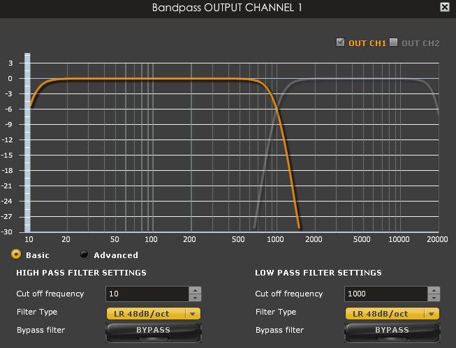
20 3.1.5 Analog Outputs PWR-ICE125 Manual Custom label Output volume PEQ control Crossover control Mute control Polarity control Compressor/limiter Output delay Custom Label The custom label feature allows you to input a user defined label for each output channels: A handy feature to remember the output configuration of your system Output volume A fader control from +12 to -70dB digital gain control Crossover Controls for the Low& High pass filters are available when clicking on the Xover (crossover) button: The log scale graph gives you the equivalent response of the applied filter. By pointing the mouse anywhere on the plotted curve, the db attenuation and respective frequency are displayed. High Pass Filter settings Low Pass Filter settings P 20
: Available in 12, 24, 48dB/oct o Butterworth (BW): Available in 6, 12, 18, 24, 30, 36, 42, 48dB/oct o Bessel: Available in 12dB/oct Each filter has different phase")

21 Cut off frequency: Select the -3dB frequency by either entering the value or using the up & down arrows of the numeric box. Filter types: o Linkwitz Riley (LR): Available in 12, 24, 48dB/oct o Butterworth (BW): Available in 6, 12, 18, 24, 30, 36, 42, 48dB/oct o Bessel: Available in 12dB/oct Each filter has different phase and amplitude characteristics. We recommend you to look online for more information about the specifics of each filter. Bypass button allows you to Enable/Disable the filter. Make sure to bypass the filter if you do not need the filter enabled Parametric Equalizer EQ band selection: Select one of the 6 x Parametric Equalizers Filter type: Select between Peak, Low Shelf, High Shelf Bypass: Disables the equalization but doesn t reset the settings. A handy tool to check the influence of equalization on your system without resetting to zero. Note that the bypass button is per-band Bypass (not overall). Linking feature: Similar to the crossover dialog box, you can link up two EQ settings together. Basic/Advanced radio button: Toggles from basic mode (i.e. input frequency) to advanced custom biquad input. Toggle from basic to Advanced EQ band selection Select the filter type Basic mode Per Band bypass EQ Per Band bypass EQ Advanced mode for custom biquad programming The Advanced mode can be used for your custom filters of external software such as Room EQ Wizard (REW). For more information about the auto-tuning feature of the minidsp, please check minidsp s website for the following application note. P 21

22 Compressor /Limiter PWR-ICE125 Manual Typical Comp/Limiter settings Comp/ Limiter metering shows real time amount of attenuation by comp/limiter Comp/ Limiter chart Bypass Comp/ Limiter A compressor/limiter allows dynamic range compression of the signal to prevent damage of your speakers. Extensive information is available online on the use of compressor/limiter. Please take the time to familiarize yourself with such processing block before using it. 3.2 Load/Save/Restore a configuration Load configuration: Use this feature to load a previously saved configuration. The file must be as.xml format and previously saved from this plug-in. For complexity reasons, inter-plug-in compatibility is not available Save configuration Use this feature to save your audio settings configuration. The following dialog box allows you to save the file anywhere on your PC as a.xml format. All 4 memory preset configurations will be saved Restore Factory default Use this feature to restore the board back to factory default. Warning that all configurations will be restored back to default from this action Upgrade firmware In order to enable some new features, the PWR-ICE may require to be flashed with a new firmware. All the required tools and firmware files are already included in the in the installation folder of the plug-in. So the first step to make sure you have everything you need is to install the new plug-in by logging to the UserDownload section. Note that firmware upgrade tools is Windows only at this point of time. A tftp client is required in the PC to download the firmware. Most operating systems come with a TFTP client built in. In Microsoft Windows, this utility is named tftp.exe. This utility is a very simple console application which can be used to download.hex file over the network to the device. WinXP/WinVista Win7 Tftp utility is disabled in Windows 7 by default, to turn it on, select: Control Panel -> Programs and Features -> Turn Windows features on or off -> TFTP Client (Note: check the checkbox to enable TFTP Client utility). Then, click the OK button. STEP by STEP to update 1. Connect the PWR-ICE device to the network through Ethernet cable. 2. Power on the PWR-ICE device. 3. Open the PWR_ICE2_1x2 plugin installed on the PC. The PC should also be connected to the same network domain and DCHP should be used to assign ip address to PC and PWR-ICE2 device. 4. The NetBIOS name of the PWR-ICE2 will appear as an Ethernet Device under the Device Tree in the plugin. (If the name doesn't appear, click the Ethernet Device folder to expand it. The name will appear under the Ethernet device folder) 5. Click the NetBIOS name listed under the Ethernet device folder to connect to the device. (e.g. Click the name: PWR-ICE2 as shown in the below example) P 22


23 6. On the menu bar, select Restore -> Upgrade Firmware, the device will go into bootloader mode with green led on the LAN port flashing. 7. The device will be disconnected and a pop-up showing: Please use this command to update the firmware: tftp Open the command prompt from Windows. You can do so with RUN - > CMD 9. Type in the command word as displayed in the pop-up in previous step. path to firmware file is the absolute path to the firmware file that you downloaded on your PC from the UserDownloads section. For this example, type: tftp put "C:\pwr-ice2.hex" 10. Hit Enter key to download the firmware to PWR-ICE2 device. P 23

24 11. While downloading, both green and orange led on the LAN port should light up. 12. The command prompt will output Transfer successful after 9~10 seconds, indicating the firmware was downloaded successfully. 13. Power off the PWR-ICE2 device. Wait for a second until all leds go off. Then, power on the device again. 14. The NetBIOS name of the PWR-ICE2 should re-appear as an Ethernet Device under the Device Tree in the PWR- ICE2_1x2 plugin. The firmware upgrade is finalized. P 24
25 4 Troubleshooting The following symptoms were found to be the most likely cause of issues. Item# Symptoms Troubleshooting recommendation If not solved go to item 1 No audio on outputs - Make sure that audio signal is shown on the RMS input meters. - Confirm the source selection is correct (Analog/Digital) - Double check that output mute buttons are not enabled - Confirm that master mute is not enabled - Confirm that you are synchronized and live 2 No audio on RMS input meters 3 Audio on input RMS meters but no audio on outputs 4 Cannot reload configuration 5 Cannot connect to the board - Check your connectivity - Double check the strength of your input signal. - Confirm that master mute is disabled - Make sure the matrix mixer is set to send audio to the output channels in a mixer plug-in - Check the output mute status for each channel - Confirm the file format of your file (.xml) - Confirm the version of the file - Check your IP settings, if no DHCP server is present, make sure your computer is not set static address. - On WinXP, confirm that you have installed.net environment. - Confirm that you do not have a firewall blocking the communication. 6 Cannot install software - Confirm that you installed the required frameworks (Adobe Air/ Microsoft.net / SP2 XP) 7 Software running in - Adobe Air environment most likely requiring a version background but not update. Connect your PC to the Internet to automatically showing get an update. 10 Problem unsolved by above suggestions - Have a look at our forums to see if someone else already had this issue. - Send us an (info@minidsp.com) with a clear explanation of the symptoms and descriptions of the troubleshooting steps you already performed n/a P 25
26 5 Mechanical drawings FRONT VIEW P 26
27 SIDE VIEW P 27
28 REAR VIEW + RECOMMENDED OPENING (RED) PWR-ICE125 Manual P 28
minidsp Balanced 2x4
 minidsp Balanced 2x4 USER MANUAL V1.0 Revision Description Date V1.0 User manual Initial version 24-12-2010 Table of content 1 System setup...3 2 minidsp Basics...4 2.1 What is a minidsp?...4 2.2 minidsp
minidsp Kit USER MANUAL V1.6 Revision Description Date V1.5 minidsp PCB revision - Rev V1.6 New minidsp PCB revision Rev
 minidsp Kit USER MANUAL V1.6 Revision Description Date V1.5 minidsp PCB revision - Rev1 31-05-2010 V1.6 New minidsp PCB revision Rev2 16-12-2010 V1.7 Jumper for RevA & B 26-03-2012 Table of content 1 System
nanodigi 2x8 USER MANUAL
 nanodigi 2x8 USER MANUAL B Revision Description Date V1.0 Initial revision 28-06-2012 V1.1 Updated section 07-05-2013 V1.2 Update of matrix mixer section 24-03-2016 www.minidsp.com P 1 Contents 1 Product
minidsp 4x10 Hd USER MANUAL
 minidsp 4x10 Hd USER MANUAL Revision Description Date V1.0 Initial revision 28-06-2012 V1.1 Updated section on volume control 03-08-2012 www.minidsp.com P 1 Contents 1 Product Introduction... 3 2 System
minidsp Kit USER MANUAL V1.5 Revision Description Date V1.0 User manual Initial version
 minidsp Kit USER MANUAL V1.5 Revision Description Date V1.0 User manual Initial version 15-12-2009 V1.1 Layout re-organization Modification on synchronization process Added section about PEQ 10-02-2010
minidsp 8x8 USER MANUAL
 minidsp 8x8 USER MANUAL Revision Description Date V1.0 Initial revision 01-07-2011 V1.1 Updated section on input/output jumpers 30-09-2011 V1.2 IR remote & Firmware upgrade instructions 26-10-2011 www.minidsp.com
minidsp Kit USER MANUAL V1.6
 minidsp Kit USER MANUAL V1.6 Important note: This user manual only applies to board of minidsp Rev2, shipped starting from early December 2010. If your board does not look like the picture below, please
minidsp Balanced Kit
 minidsp Balanced Kit USER MANUAL V1.4 Revision Description Date V1.0 User manual Initial version 24-09-2010 V1.1 Sensitivity Jumper clarifications 24-09-2010 V1.2 Updated various sections 23-12-2010 V1.3
OpenDRC-DI USER MANUAL.
 OpenDRC-DI USER MANUAL Manual revision Description Date V1.0 Initial revision 18-02-2012 V1.1 Firmware upgrade information 18-04-2012 V1.2 DSP upgrade step by step 17-07-2012 www.minidsp.com P 1 Contents
minidsp Kit USER MANUAL V1.6
 minidsp Kit USER MANUAL V1.6 Important note: This user manual only applies to board of minidsp Rev2, shipped starting from early December 2010. If your board does not look like the picture below, please
PWR-ICE125 PWR-ICE250. User Manual DSP-CONTROLLED PLATE AMPLIFIER
 PWR-ICE125 PWR-ICE250 DSP-CONTROLLED PLATE AMPLIFIER User Manual minidsp Ltd, Hong Kong / www.minidsp.com / Features and specifications subject to change without prior notice 1 Revision history Revision
OpenDRC-AN USER MANUAL.
 OpenDRC-AN USER MANUAL Manual revision Description Date V1.0 Initial revision 13-07-2012 www.minidsp.com P 1 Contents 1 Product Introduction... 3 2 System Connectivity... 5 2.1 Connectivity... 5 2.2 Typical
PWR-16. User Manual 16-CHANNEL MULTIZONE AUDIO POWER AMPLIFIER
 PWR-16 16-CHANNEL MULTIZONE AUDIO POWER AMPLIFIER User Manual minidsp Ltd, Hong Kong / www.minidsp.com / Features and specifications subject to change without prior notice 1 Revision history Revision Description
PWR-DSP2. DSP processed Plate Amplifier User Manual. Version 1.0. PWR-DSP2 User Manual. Revision Description Date
 PWR-DSP2 DSP processed Plate Amplifier User Manual Version 1.0 Revision Description Date V1.0 User manual Initial version 01-08-2011 Page 1 of 23 PRODUCT DESCRIPTION PWR-DSP2 User Manual The PWR-DSP2 answers
OWNER S MANUAL CD-2 V 1.3
 OWNER S MANUAL CD-2 V 1.3 2 TABLE OF CONTENTS WARNINGS... 3 ACCESSORIES... 4 REMOTE CONTROL... 5 FRONT PANEL... 6 REAR PANEL... 7 MENU SYSTEM... 8 NOTES OF IMPORTANCE... 10 CONNECTORS... 11 TECHNICAL SPECIFICATIONS...
BS 181 SINGLE CHANNEL POWER SUPPLY USER MANUAL
 BS 181 SINGLE CHANNEL POWER SUPPLY USER MANUAL Issue 2011 ASL Intercom BV DESIGNED & MANUFACTURED BY: ASL Intercom B.V. Zonnebaan 42 3542 EG Utrecht The Netherlands Tel: +31 (0)30 2411901 Fax: +31 (0)30
PWR-DSP3. DSP processed Plate Amplifier User Manual. Version 1.0. PWR-DSP3 User Manual. Revision Description Date
 PWR-DSP3 DSP processed Plate Amplifier User Manual Version 1.0 Revision Description Date V1.0 User manual Initial version 01-06-2011 Page 1 of 27 PRODUCT DESCRIPTION PWR-DSP3 User Manual The PWR-DSP3 answers
BS 287 DUAL CHANNEL POWER SUPPLY. User Manual. January 2017 V1.0
 BS 287 DUAL CHANNEL POWER SUPPLY User Manual January 2017 V1.0 Table of contents 1.0 SAFETY INSTRUCTIONS... 3 2.0 GENERAL DESCRIPTION PS 289... 4 3.0 MECHANICAL INSTALLATION... 5 4.0 MAINS POWER & SAFETY
Blonde On Blonde OWNER S MANUAL SWR SCOTTSDALE, AZ USA
 Blonde On Blonde OWNER S MANUAL SWR SCOTTSDALE, AZ USA IMPORTANT SAFETY INSTRUCTIONS CAUTION: TO REDUCE RISK OF ELECTRIC SHOCK, DO NOT REMOVE THE COVER OR BACK. NO USER-SERVICEABLE PARTS INSIDE. PLEASE
Ares. Modular Audiophile System. by Thrax Audio. Operating Manual. Manual issued 15/03/2018 CAUTION
 Ares Modular Audiophile System by Thrax Audio Operating Manual Manual issued 15/03/2018 CAUTION THE UNIT CONTAINS NO USER SERVICEABLE PARTS. DO NOT REMOVE THE COVERS. LETHAL VOLTAGES ARE PRESENT WITHIN
QIT600F1 USER'S GUIDE
 QIT600F1 USER'S GUIDE 1 IMPORTANT SAFEGUARDS Warnings: 1. Read all of these instructions. Save these instructions for later use, please. 2. Unplug this monitor from the wall outlet before cleaning. Do
miniambio 2.0 USER MANUAL V1.0 Revision Description Date V1.0 User manual Initial version P 1 of 12
 miniambio 2.0 USER MANUAL V1.0 Revision Description Date V1.0 User manual Initial version 10-10-2010 P 1 of 12 1 miniambio Basics To better understand the benefits of Ambiophonics, you first need to understand
BS 181 SINGLE CHANNEL POWER SUPPLY USER MANUAL
 BS 181 SINGLE CHANNEL POWER SUPPLY USER MANUAL August 2016 This product is designed and manufactured by: ASL Intercom B.V. Zonnebaan 42 3542 EG Utrecht The Netherlands Phone: +31 (0)30 2411901 Fax: +31
PREMIUMAUDIOVIDEOANDPOWERPRODUCTS V-RVC-PRO. Owners Manual
 PREMIUMAUDIOVIDEOANDPOWERPRODUCTS V-RVC-PRO Owners Manual IMPORTANT NOTE: THIS OWNER'S MANUAL IS PROVIDED AS AN INSTALLATION AND OPERATING AID. FACTOR ELECTRONICS DOES NOT ASSUME ANY RESPONSIBILITY AS
Professional Digital Audio Processor. SOLTON DSP 206 Operation Manual
 Professional Digital Audio Processor SOLTON DSP 206 INPORTANT SAFETY INSTRUCTIONS TO PREVENT ELECTRIC SHOCK DO NOT REMOVE TOP OR BOTTOM COVERS.NO USER SERVICEABLE PARTS INSIDE.REFER SERVICING TO QUALIFIED
MODEL 805 USER MANUAL
 MODEL 805 USER MANUAL All Rights Reserved Page 1 of 12 UNPACKING & INSPECTION Save all packing materials they are required for returns and warranty service. Inspect the 805 and packing materials for any
VOICE-ACTIVATED INTERCOM SYSTEM
 VOICE-ACTIVATED INTERCOM SYSTEM Owner s Manual For Wireless Intercom Model WHI-4CUPG EXPLANATION OF GRAPHIC WARNING SYMBOLS This symbol is intended to alert the user to the presence of un-insulated dangerous
RIO R22 & R44. Quick Start Guide for all variants
 RIO R22 & R44 Quick Start Guide for all variants Important Safety Information 1. READ THESE INSTRUCTIONS All the safety and operating instructions should be read before the product is operated. 2. KEEP
YST-SW20 SUBWOOFER SYSTEM OWNER S MANUAL. Active Servo Technology
 CAUTION SUBWOOFER SYSTEM Active Servo RISK OF ELECTRIC SHOCK DO NOT OPEN CAUTION: TO REDUCE THE RISK OF ELECTRIC SHOCK DO NOT REMOVE COVER (OR BACK). NO USER-SERVICEABLE PARTS SIDE. REFER SERVICG TO QUALIFIED
PREMIUMAUDIOVIDEOLIGHTINGANDPOWERPRODUCTS
 FACTOR ELECTRONICS PREMIUMAUDIOVIDEOLIGHTINGANDPOWERPRODUCTS V-RVC Owners Manual IMPORTANT NOTE: THIS OWNER'S MANUAL IS PROVIDED AS AN INSTALLATION AND OPERATING AID. FACTOR ELECTRONICS DOES NOT ASSUME
Introduction. Specifications. Network
 Introduction When it comes to control hardware, it is necessary to provide an easy yet powerful interface for the personnel in charge. XPanel Touch is created with this purpose in mind. The menu names
2 CHANNEL, CLASS D AMPLIFIERS PA2X25 PA2X60 PA2X125 PA2X150. pulseaudio1.com vanco1.com
 2 CHANNEL, CLASS D AMPLIFIERS PA2X25 PA2X60 PA2X125 PA2X150 pulseaudio1.com vanco1.com 800.626.6445 DEAR CUSTOMER Thank you for purchasing this product. For optimum performance and safety, please read
Us U er e r G u G i u de d AX A 3 X DA D N A T N E T I/O / O Car a d r d
 User Guide AX32 DANTE I/O Card IMPORTANT SAFETY INSTRUCTIONS READ AND KEEP THESE INSTRUCTIONS WARNING when using electric products, basic precautions should be followed, including the following: Read all
C-300 Preamplifier User s guide
 C-300 Preamplifier User s guide C-300 Preamplifier User s guide Specifications: Contents: Output: Max 7.5Vrms unbalanced (RCA) or 15Vrms balanced (XLR) SPECIFICATIONS Page 2 Phono: istortion, line stage:
USER S MANUAL. Dual Channel 15 Band EQ USB. 19" DIGITAL (482mm) DS-EQ215 PARAMETER OUT EQUALIZER ESCAPE
 DS-EQ215 PARAMETER OUT EQUALIZER ESCAPE") DS-EQ215 USER S MANUAL IN PARAMETER DS-EQ215 OUT EQUALIZER ESCAPE Dual Channel 15 Band EQ 19" DIGITAL (482mm) USB Contents Introduction...1 Safety Instructions... 2 Getting Started with Front Panel Controls...
DS-EQ215 USER S MANUAL IN PARAMETER DS-EQ215 OUT EQUALIZER ESCAPE Dual Channel 15 Band EQ 19" DIGITAL (482mm) USB Contents Introduction...1 Safety Instructions... 2 Getting Started with Front Panel Controls...
PCM60A 100W MAX P.A. AMPLIFIER.
 PCM60A 100W MAX P.A. AMPLIFIER www.pyleaudio.com IMPORTANT SAFETY INSTRUCTIONS 1. Read Instructions All the safety and operating instructions should be read before the appliance is operated. 2. Retain
U-DAC8. User Manual 8-CHANNEL HIGH-RESOLUTION USB DAC
 U-DAC8 8-CHANNEL HIGH-RESOLUTION USB DAC User Manual minidsp Ltd, Hong Kong / www.minidsp.com / Features and specifications subject to change without prior notice 1 Revision history Revision Description
Users Manual. Pronomic TAS-18 Active Touring System
 Users Manual Pronomic TAS-18 Active Touring System Version 01/2012 IMPORTANT SAFETY INSTRUCTIONS The apparatus shall not be exposed to dripping or splashing and that no objects filled with liquids, such
SUBWOOFER SYSTEM YST-MSW10
 ACTIVE SERVO PROCESSING SUBWOOFER SYSTEM YST-MSW10 Active Servo SUBWOOFER SYSTEM YST-MSW10 Active Servo HIGH CUT HIGH LOW OWNER S MANUAL MANUAL DE INSTRUCCIONES CAUTION RISK OF ELECTRIC SHOCK DO NPT OPEN
PS 289 DUAL CHANNEL POWER SUPPLY USER MANUAL
 PS 289 DUAL CHANNEL POWER SUPPLY USER MANUAL August 2016 This product is designed and manufactured by: ASL Intercom B.V. Zonnebaan 42 3542 EG Utrecht The Netherlands Phone: +31 (0)30 2411901 Fax: + 31
DAB A d a pt e r 3+ Dear Customer,
 Dear Customer, Quality has always been our driving force and founding Argon Audio is a natural extension of this philosophy. We have 20 years' experience in creating and specifying high quality products,
HSC-42. HDMI 4k2k Video Up/Down Scaler
 INSTRUCTION MANUAL HSC-42 HDMI 4k2k Video Up/Down Scaler SAFETY AND NOTICE 1. Read these instructions. 2. Keep these instructions. 3. Heed all warnings. 4. Follow all instructions. 5. Do not use this apparatus
AMP20. User Manual.
 AMP20 User Manual www.audac.eu 2 Index Introduction 5 Precautions 6 Safety requirements 6 Caution servicing 7 EC Declaration of Conformity 7 Waste of Electrical and Electronic Equipment (WEEE) 7 Chapter
NEUPANEL SERIES. User Manual for Neutrino/Uno/Rio
 NEUPANEL SERIES User Manual for Neutrino/Uno/Rio 1 Important Safety Information 1. READ THESE INSTRUCTIONS All the safety and operating instructions should be read before the product is operated. 2. KEEP
WARNINGS AND PRECAUTIONS... 3 PACKING LIST... 5 FRONT PANEL... 5 REAR PANEL... 6 MENU SETTINGS... 7 EXAMPLE SETUP SPECIFICATIONS...
 AUDIO DELAY sax AD-1 aam Quick Start Guide WARNINGS AND PRECAUTIONS... 3 PACKING LIST... 5 FRONT PANEL... 5 REAR PANEL... 6 MENU SETTINGS... 7 EXAMPLE SETUP... 11 SPECIFICATIONS... 11 SERVICE & SUPPORT...
PS8 - II. Professional Power Sequencer. User s Manual
 PS8 - II Professional Power Sequencer User s Manual IMPORTANT SAFETY INSTRUCTIONS READ FIRST This symbol, whenever it appears, alerts you to the presence of uninsulated dangerous voltage inside the enclosure.
P75 Dual Source Power Amplifier Installation Manual
 P75 Dual Source Power Amplifier Installation Manual SAFETY INSTRUCTIONS CAUTION: TO REDUCE THE RISK OF ELECTRIC SHOCK, DO NOT REMOVE THE COVER. NO USER- SERVICEABLE PARTS INSIDE. REFER SERVICING TO QUALIFIED
DSM26 DIGITAL SPEAKER MANAGEMENT SYSTEM. Order ref: UK User Manual. Features
 DSM26 DIGITAL SPEAKER MANAGEMENT SYSTEM Order ref: 170.665UK User Manual Features 2 inputs, 6 outputs, fully balanced Independent parametric EQs Delay and Compressor/Limiter/Gate functions All inputs/outputs
7-Port Fast Charging Station NAP Instruction Manual Please read carefully before use and keep for future reference.
 7-Port Fast Charging Station NAP-7000 Instruction Manual Please read carefully before use and keep for future reference. Thank You We know you have many choices when it comes to technology; thank you for
1 Mic-In / 1 Guitar-In, 2-Out Professional vocal recording USB Interface. User manual
 1 Mic-In / 1 Guitar-In, 2-Out Professional vocal recording USB Interface User manual Important Safety Instructions 1. Read this manual thoroughly before using this unit. 2. Keep this manual for future
2 Mic/1-Guitar in, 2 Line out recording USB Interface. User manual
 2 Mic/1-Guitar in, 2 Line out recording USB Interface User manual Important Safety Instructions 1. Read this manual thoroughly before using this unit. 2. Keep this manual for future reference. 3. Take
Digital Speaker Management System
 Digital Speaker Management System DSM-26LAN Order No. 25.5760 DSM-48LAN Order No. 25.5770 INSTRUCTION MANUAL ELECTRONICS FOR SPECIALISTS ELECTRONICS FOR SPECIALISTS ELECTRONICS FOR SPECIALISTS ELECTRONICS
OPERATING INSTRUCTIONS PA AMPLIFIER P-1812
 OPERATING INSTRUCTIONS PA AMPLIFIER P-1812 Please follow the instructions in this manual to obtain the optimum results from this unit. We also recommend that you keep this manual handy for future reference.
PORTABLE WIRELESS PA SYSTEM WITH LITHIUM -ION RECHARGEABLE BATTERY AWP6042 OWNER S MANUAL. Handheld Microphone Headset Transmitter
 PORTABLE WIRELESS PA SYSTEM WITH LITHIUM -ION RECHARGEABLE BATTERY AWP6042 OWNER S MANUAL X1 Headset Microphone AWX6042H VHF Wireless Headset Transmitter Handheld Microphone Headset Transmitter Thank you
U-300 Unity Amplifier User s guide
 U-300 Unity Amplifier User s guide U-300 Unity Amplifier User s guide Specifications: Contents: Output: 2 x 300 W/8 Ohm, 2 x 600 W/4 Ohm SPECIFICATIONS Page 2 Distortion:
Mytek DIO DANTE Card. User Manual
 Mytek DIO DANTE Card User Manual ver. 1.2 / March 2015 Mytek 2015 Page: 1 / 25 This manual may be updated Download the newest version at: http:///download_library/ For technical support, technical tips
Quick Start Guide Rio Series R22 and R44 Models
 Rio Series R22 & R44 Dante Interface Models - Quick Start Guide 1. What s in the Box The Rio Series R22-P, or R44-P, or R22-WP-X, or R22-WP-M, Dante interface device hardware This hard copy of the Quick
Cantata m100 Amplifier
 Cantata m100 Amplifier Getting Started Guide www.resolutionaudio.com +1.415.553.4100 Safety Information CAUTION RISK OF ELECTRICAL SHOCK DO NOT OPEN CAUTION: TO REDUCE THE RISK OF ELECTRICAL SHOCK, DO
HDMI MATRIX SWITCHER B-120-HDMATRIX-4x4/8x8 CONFIGURATION UTILITY MANUAL
 HDMI MATRIX SWITCHER B-120-HDMATRIX-4x4/8x8 CONFIGURATION UTILITY MANUAL IMPORTANT SAFETY INSTRUCTIONS To reduce the risk of fire or electric shock, read and follow all instructions and warnings in this
INSTRUCTION MANUAL DISTRIBUTION UNIT. Please read this manual thoroughly before use, and keep it handy for future reference.
 INSTRUCTION MANUAL DISTRIBUTION UNIT Please read this manual thoroughly before use, and keep it handy for future reference. ISSUE 1 May 2006 LIMITATION OF LIABILITY THE INFORMATION IN THIS PUBLICATION
DPR-34+ GB Revision 2
 DPR-34+ GB Revision 2 1. 2. 3. 4. 5. 6. 7. 8. 9. Important Safety Instructions Read these instructions. Keep these instructions. Heed all warnings. Follow all instructions. Do not use this apparatus near
Monochrome Camera. Features. User manual
 Monochrome Camera LTC0330/11 LTC0330/21 LTC0350/11 LTC0350/21 LTC0330/51 LTC0330/61 LTC0350/51 LTC0350/61 Features To obtain the best results from your new camera, read these instructions carefully before
EQ230 / EQ430 Operation Manual
 EQ230 / EQ430 Operation Manual The EQ230 and EQ430 with X-Drive processing are two and four channel precision 30-band graphic equalizers designed to elevate the performance of any system. The XD Network
DVI KVM. Extra Long Range Extender Over One CAT5. User Manual EXT-DVIKVM-ELR. Release A8
 DVI KVM Extra Long Range Extender Over One CAT5 EXT-DVIKVM-ELR User Manual Release A8 Important Safety Instructions 1 Read these instructions 2 Keep these instructions 3 Heed all warnings 4 Follow all
OWNER S MANUAL GEQ 131/ 131LF GEQ 215/ 215LF GEQ 231. Single Channel 31 Band Graphic Equalizer. 2 Channel 15 Band Graphic Equalizer
 20 25 31.5 40 50 63 80 0 125 160 200 250 315 400 500 630 800 1K 1.25K 1.6K 2K 2.5K 3.15K 4K 5K 6.3K 8K K 12.5K 16K 20K +12 +6 +3 0-3 GEQ 131LF 5 31 BAND GRAPHIC EQUALIZER 15 40 60 7K 15K 22K BYPASS RANGE
PS 680 SIX CHANNEL POWER SUPPLY WITH AUX MATRIX USER MANUAL
 PS 680 SIX CHANNEL POWER SUPPLY WITH AUX MATRIX USER MANUAL Issue 2010 ASL Intercom BV DESIGNED AND MANUFACTURED BY: ASL INTERCOM B.V. ZONNEBAAN 42 3542 EG UTRECHT THE NETHERLANDS PHONE: +31 (0)30 2411901
undx2io 2-in/2-out Dante Wallplate
 2-in/2-out Dante Wallplate Date 09/20/2013 Revision 01 Attero Tech, LLC 1315 Directors Row, Suite 107, Ft Wayne, IN 46808 Phone 260-496-9668 Fax 260-496-9879 www.atterotech.com 614-00016-01 IMPORTANT SAFETY
Thank you for your purchase of the Supa-Charger! Features Include:
 Owner s Manual Thank you for your purchase of the Supa-Charger! The Supa-Charger is a High Performance Pedal Power Supply that will power any battery operated effect devices that require 9, 12 or 16 volts.
FUTURE CALL. Future Call Model FC-1204 Totally Hands Free Voice Activated Dialing and Answering Telephone OWNER S MANUAL AND OPERATING INSTRUCTIONS
 FUTURE CALL Future Call Model FC-1204 Totally Hands Free Voice Activated Dialing and Answering Telephone OWNER S MANUAL AND OPERATING INSTRUCTIONS Welcome to your new Totally Hands Free Voice Activated
U-150 Integrated Amplifier User s guide
 U-150 Integrated Amplifier User s guide U-150 Integrated Amplifier User s guide Specifications: Contents: Output: Phono: Line: Digital: Volume control: Dimensions: Weight: 2 300W/8 Ohm, 2 600W/4 Ohm Distortion:
User s Guide. Digital Whole Home Audio Distribution System
 User s Guide Digital Whole Home Audio Distribution System Document Number 62R00-1 Rev A October, 2006 Copyright 2006 Home Automation, Inc. All Rights Reserved Precautions Exposure to extremely high noise
HP-101 HEADPHONE AMPLIFIER
 HP-101 HEADPHONE AMPLIFIER User s Guide Before using your headphone amplifier, please read this User s Guide thoroughly and keep it for future reference. IMPORTANT Safety Instructions Please read these
FOOT CONTROLLER FCV100
 CV NORM OUTPUT2 OUTPUT1 MIN VOL 0 10 User Manual FOOT CONTROLLER FCV100 Ultra-Flexible Dual-Mode Foot Pedal for Volume and Modulation Control 2 FOOT CONTROLLER FCV100 User Manual Table of Contents Thank
This manual describes the installation, setup and operation of this equipment in details.
 About This Manual This manual describes the installation, setup and operation of this equipment in details. Please read it carefully to make sure you can operate the multiplexer correctly. Important Avoid
CPD SERIES OPERATING MANUAL AND USER GUIDE. Professional Power Amplifier.
 CPD SERIES Professional Power Amplifier OPERATING MANUAL AND USER GUIDE www.wharfedalepro.com TABLE OF CONTENTS TABLE OF CONTENTS... 1 IMPORTANT WARNINGS & SAFETY INSTRUCTIONS... 2 INTRODUCTION... 3 ABOUT
User s Guide. Digital Whole Home Audio Distribution System. Includes 8 audio source inputs and 8 amplified audio zones
 User s Guide Digital Whole Home Audio Distribution System FEATURES Includes 8 audio source inputs and 8 amplified audio zones Hi-Fi2 SYSTEM Optional Hi-Fi2 Expansion Kit adds 8 more zones (16 total) Super
AUDIO DELAY BOX WITH MICROPHONE INPUT AD-100M. Instruction manual.
 AUDIO DELAY BOX WITH MICROPHONE INPUT AD-100M Instruction manual www.datavideo.com Table of Contents FCC COMPLIANCE... 3 WARNINGS AND PRECAUTIONS... 3 WARRANTY... 4 STANDARD WARRANTY... 4 THREE YEAR WARRANTY...
CANTEEN 6000 Portable Battery Pack NAP-30. Instruction Manual Please read carefully before use and keep for future reference.
 CANTEEN 6000 Portable Battery Pack NAP-30 Instruction Manual Please read carefully before use and keep for future reference. Thank You We know you have many choices when it comes to technology; thank you
Azimut. Minimalist design, maximum connectivity. Reference Guide
 Minimalist design, maximum connectivity Complete audio solution with plug and play capabilities Bluetooth connectivity Onboard Spotify Dedicated app via Wi-F Thank you for choosing a K-array product! To
TIBO AUDIO PA500 Owner s manual
 TIBO AUDIO PA500 Owner s manual Please read this manual carefully before using this product and then retain for future reference. 1 CONTENTS CONTENTS 3 WHAT S IN THE BOX 4 SAFETY Safety precautions 5
DM25, DM40. Compact 100V mixer-amplifiers with Bluetooth. Item ref: UK, UK User Manual
 DM25, DM40 Compact 100V mixer-amplifiers with Bluetooth Item ref: 953.108UK, 953.109UK User Manual Caution: Please read this manual carefully before operating Damage caused by misuse is not covered by
HDP3, PDC-2.6 and PDC-2.6P User's Manual
 HDP3, PDC-2.6 and PDC-2.6P User's Manual Professional Digital Correction for Installers and End Users Copyright Copyright 2004-2008 DEQX Pty. Ltd. DEQX Calibrated is a trademark of DEQX Pty. Ltd. All other
Important Safety Information
 XA User Manual 1 Important Safety Information 1. READ THESE INSTRUCTIONS All the safety and operating instructions should be read before the product is operated. 2. KEEP THESE INSTRUCTIONS The safety and
1 Mic-In / 2-Out Professional Vocal Recording USB Interface. User manual
 1 Mic-In / 2-Out Professional Vocal Recording USB Interface User manual Important Safety Instructions 1. Read this manual thoroughly before using this unit. 2. Keep this manual for future reference. 3.
IMPORTANT SAFETY INSTRUCTIONS
 IMPORTANT SAFETY INSTRUCTIONS When using this electronic device, basic precautions should always be taken, including the following: 1. Read all instructions before using the product. 2. Do not use this
BS 217 DUAL CHANNEL MASTER STATION USER MANUAL
 BS 217 DUAL CHANNEL MASTER STATION USER MANUAL August 2016 This product is designed and manufactured by: ASL Intercom B.V. Zonnebaan 42 3542 EG Utrecht The Netherlands Phone: +31 (0)30 2411901 Fax: +31
WARNING! CAUTION: TO REDUCE THE RISK OF ELECTRIC SHOCK, DO NOT REMOVE THE COVER OF THIS UNIT. THERE ARE NO USER
 PTA44BT 4 Channel Audio Amplifier Multi-Source 1/4 Audio/Microphone inputs MP3/USB/SD Readers/ FM radio, Built-in Wireless BT Audio Streaming (500 Watts) WARNING! CAUTION: TO REDUCE THE RISK OF ELECTRIC
OLi POWA-5 Active Monitors
 Active Monitors User Manual : English Contents Important Information... 3 Front & Rear Panels... 4 Remote Control... 5 Connecting Your Speakers... 6 Bluetooth Function... 7 Use with ipod / MP3... 8 Use
DPR-39. GB Revision 1
 DPR-39 GB Revision 1 Important Safety Instructions 1. Read these instructions. 2. Keep these instructions. 3. Heed all warnings. 4. Follow all instructions. 5. Do not use this apparatus near water. 6.
Plena Universal Pre-amplifier. Installation and Operating Manual LBB 1920
 Plena Universal Pre-amplifier en Installation and Operating Manual LBB 190 Plena Universal Pre-amplifier Installation and Operating Manual Important safeguards en Important safeguards 1 Read instructions
1. Introduction Features Checking List Installation Install the Pedestal Connect Your Monitor to Computer...
 E27M5G 27 " W User Manual M Series L E D B A C K L I G H T M o n i to r Content F.C.C STATEMENT IMPORTANT SAFEGUARDS 1. Introduction 6 1.1 Features...6 1.2 Checking List...6 2. Installation 7 2.1 Install
THANK YOU! Crush PiX 20L. Thank you for choosing Orange. You are now a member of the Legendary British Guitar Amplifier owners club!
 1 THANK YOU! Thank you for choosing Orange. You are now a member of the Legendary British Guitar Amplifier owners club! Since 168 when the company was founded, Orange has been a pioneering force in the
IMPORTANT SAFETY INSTRUCTIONS. 7) Do not block any ventilation openings. Install in accordance with the manufacturer s instructions.
 Do not block any ventilation openings. Install in accordance with the manufacturer s instructions.") TEDDY stage monitor IMPORTANT SAFETY INSTRUCTIONS THE LIGHTNING FLASH WITH ARROWHEAD SYMBOL, WITHIN AN EQUILATERAL TRIANGLE, IS INTENDED TO ALERT THE USER TO THE PRESENCE OF UNINSULATED DANGEROUS VOLTAGE
TEDDY stage monitor IMPORTANT SAFETY INSTRUCTIONS THE LIGHTNING FLASH WITH ARROWHEAD SYMBOL, WITHIN AN EQUILATERAL TRIANGLE, IS INTENDED TO ALERT THE USER TO THE PRESENCE OF UNINSULATED DANGEROUS VOLTAGE
Marshall Lynx LCD Universal Monitors
 Marshall Lynx LCD Universal Monitors User Manual Marshall Industrial Video/Security Div. For more information, contact Marshall Electronics, Industrial Video & Security (800) 800-6608 www.mars-cam.com
HeadAmp6 PROFESSIONAL SIX CHANNEL HEADPHONE AMPLIFIER OPERATION MANUAL
 HeadAmp6 PROFESSIONAL SIX CHANNEL HEADPHONE AMPLIFIER OPERATION MANUAL 1 IMPORTANT SAFETY INSTRUCTIONS READ FIRST This symbol, wherever it appears, alerts you to the presence of uninsulated dangerous voltage
SOUNDSTICKS WIRELESS. Setup Guide. Downloaded from
 SOUNDSTICKS WIRELESS Setup Guide English Japanese Simplified Chinese 2 SOUNDSTICKS WIRELESS 1. Read these instructions. 2. Keep these instructions. 3. Heed all warnings. 4. Follow all instructions. 5.
A Watt Stereo Amplifier
 A0240 40 Watt Stereo Amplifier 8 The A0240 is a 2-channel 40 Watt class D amplifier. It can be used to power a small 1-room audio system or integrated with Channel Vision s A0302 to provide supplemental
Kogan Bluetooth Karaoke System with Dual Microphones KAKAR2MICA
 Kogan Bluetooth Karaoke System with Dual Microphones KAKAR2MICA K TABLE OF CONTENTS SAFETY & WARNINGS...1 IMPORTANT SAFETY INSTRUCTIONS...1 AC CONNECTION...2 LOCATION OF CONTROLS...3 ASSEMBLY AND CONNECTIONS...4
VM SERIES Rackmount 100V mixer-amplifiers
 VM SERIES Rackmount 100V mixer-amplifiers VM60, VM120, VM240Z Caution: Please read this manual carefully before operating Damage caused by misuse is not covered by the warranty Introduction Thank you for
4 x 8 DSP DIGITAL SIGNAL PROCESSOR FOR HOME AND CAR AUDIO. Model: DSP-408 User Manual
 4 x 8 DSP DIGITAL SIGNAL PROCESSOR FOR HOME AND CAR AUDIO Model: DSP-408 User Manual Table of Contents 2. Table of Contents 3. Product Overview/General Safety Instructions/Box Contents 4. DSP Features