HD THERMOCOUPLE THERMOMETER ENGLISH
|
|
|
- Aubrey Mitchell
- 6 years ago
- Views:
Transcription
1 REV. 1.4 Mar., 30 th 2007 HD THERMOCOUPLE THERMOMETER ENGLISH Our instruments' quality level is the results of the product continuous development. This can bring about differences between the information written in this manual and the instrument that you have purchased. We cannot entirely exclude errors in the manual, for which we apologize. The data, figures and descriptions contained in this manual cannot be legally asserted. We reserve the right to make changes and corrections without prior notice.


2 Thermocouple Thermometer HD
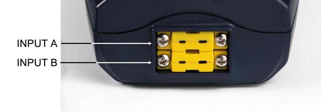
3 HD Inputs A and B for two thermocouples, with standard miniature connectors. 2. Battery symbol: displays the battery charge level. 3. Function indicators. 4. Secondary display line. 5. DATA/ENTER key: during normal operation displays the maximum (MAX), the minimum (MIN) and the average (AVG) of current measurements; in the menu, confirms the current selection. 6. CLR/ESC key: during normal operation resets the maximum, the minimum and the average of current measurements; in the menu, it resets the value set with the arrows. 7. HOLD/ key: freezes the measurement display during normal operation; in the menu, increases the current value. 8. A-B/MENU key: during normal operation, it displays in the secondary line the difference of the temperatures measured by the probes connected to the inputs A and B; when pressed together with the DATA key, it allows to open the menu. 9. REL/ key: during normal operation enables the relative measurement (displays the difference between the current value and the logged value when the key is pressed); in the menu, decreases the current value. 10. ON-OFF/AUTO-OFF key: turns the instrument on and off; when pressed together with the HOLD key, disables the AutoPowerOff function. 11. MAX (maximum value), MIN (minimum value) and AVG (average value) symbols. 12. Main display line. 13. Line for symbols and comments
4 TABLE OF CONTENTS 1. GENERAL CHARACTERISTICS DESCRIPTION OF THE FUNCTIONS THE PROGRAMMING MENU PROBES AND MEASUREMENTS TEMPERATURE MEASUREMENT CALIBRATION OF THE INSTRUMENT ON LINE WITH THE PROBE(S) Calibration sequence WARNINGS INSTRUMENT SIGNALS AND FAULTS LOW BATTERY WARNING AND BATTERY REPLACEMENT WARNING ABOUT BATTERY USE INSTRUMENT STORAGE NOTES ABOUT WORKING AND OPERATIVE SAFETY TECHNICAL CHARACTERISTICS ORDER CODES THERMOCOUPLE PROBES
5 1. GENERAL CHARACTERISTICS The Thermocouple Thermometer Model HD is a portable instrument with two inputs A and B. It measures the temperature of the two input channels, and can calculate the difference between the two channels (A-B). It is fitted with a large LCD display for excellent visualization of the measured data. The Thermometer Model HD measures the temperature using immersion, penetration, contact or air probes. The sensor can be a thermocouple chosen among the following types: Type K Type J Type T Type E The instrument accepts the input of one, or two, thermocouples of the same type (K-J-T-E) even in a different form. The units of measurement are the following: 1. C (Celsius degrees) 2. F (Fahrenheit degrees). Using the Max, Min and Avg function of this instrument respectively obtains also the maximum, minimum or average values. Other available functions are: the relative measurement REL; the HOLD function; the A-B function; the automatic turning off which can also be disabled. See chapter 2 for further information. The instrument is provided with the factory calibration. It is also possible to perform a "User Calibration" of instrument+probe (see chapters 3 and 4)


6 2. DESCRIPTION OF THE FUNCTIONS The keyboard of the Thermocouple Thermometer Model HD is composed of doublefunction keys. The function on the key is the "main function", while the one above the key is the "secondary function". When the instrument is in standard measurement mode, the main function is active. In the menu, the secondary function is enabled; press the DATA+(A-B) keys together to open the menu. The pressing of a key is accompanied by a short confirmation "beep": a longer "beep" sounds if the wrong key is pressed. Each key specific function is described in detail below. The HD measures the temperature at the two inputs: the temperature measurement at the "A" input is displayed in the main line, while the secondary line shows the value at the "B" input. ON-OFF and AUTO-OFF key This key has two functions: ON/OFF: to turn the instrument on press ON, to turn it off press OFF. The turning on enables all display segments for a few seconds, and then the type of calibration enabled (CAL FACT = factory calibration; CAL USER = user calibration). AUTO/OFF: the AutoPowerOff function can be disabled by simultaneously pressing this key and the "HOLD" key when turning the instrument on. If no probe is connected to one of the input connectors, the "BURN" message appears in the corresponding line, that is, in the first line for input "A" and in the second line for input "B". Disabling of the automatic turning off The instrument has an AutoPowerOff function that automatically turns the instrument off after about 8 minutes if no key is pressed during the intervening time. Press simultaneously the ON/OFF key and the HOLD key to disable this function. In this case, remember to turn the instrument off using the ON/OFF key: disabling of the automatic turning off is shown by the blinking battery symbol
7 DATA/ENTER key The DATA key is used for the following functions: DATA: during normal measurement, by pressing this key once the maximum (MAX) value of the measurements captured by the probes connected to the instrument is displayed, updating it with the acquisition of new samples; - by pressing this key again the minimum (MIN) value is displayed; - by pressing this key a third time the average (AVG) value is displayed. The acquisition frequency is once a second. The MAX, MIN and AVG values remain in the memory until the instrument is on, even after exiting the DATA display function. When the instrument is off, the previously memorized data are cleared. Upon turning on, the instrument automatically starts memorizing the MAX, MIN and AVG values. To reset the previous values and start with a new measurement session, press CLR until the FUNC_CLRD message appears. ENTER: once the MENU has been opened with the DATA+UNIT keys, the DATA key will perform the ENTER function and the MENU can be browsed and the displayed parameter confirmed. CLR/ESC key The CLR key has two functions: CLEAR (CLR): allows to reset the maximum (MAX), minimum (MIN) and average (AVG) value of the captured measurements; ESC: once the MENU has been opened with the DATA+UNIT keys, the CLR key will allow to cancel the parameters set using the and arrows. HOLD/ key The HOLD key is used for the following functions: HOLD: by pressing this key the current measurement update is stopped and the "HOLD" message will appear in the upper left-hand corner of the display. To return to the current measurement, press the key again. : once the MENU has been opened with the DATA+UNIT keys, the key will allow to increase the value of the selected parameter. Pressed together with the ON/OFF key, during turn on, the AutoPowerOff function is disabled (see the description of the ON/OFF key)
8 A-B/MENU key The A-B key is used for the following functions: A-B: in measurement mode, it displays in the secondary line the difference of the temperatures measured by the probes connected to the inputs A and B, and indicates "ERR" if one of the probes is in error (not connected, faulty or overrange). To end the function, press the key again. MENU: in the menu three items can be set (see chapter 3): 1. Selection of the unit of measurement for temperature: C or F. 2. Selection of the type of Thermocouple: K, J, T, E. 3. Starting the User calibration procedure. - the menu is opened by pressing simultaneously DATA+(A-B): the first item of the instrument programming menu will appear; - use the and arrows (respectively located above the HOLD and REL keys) to modify the displayed value; - press DATA/ENTER to confirm the modification and go onto the next item; - press CLR/ESC to cancel the modification; - to exit the menu, press the A-B/MENU key again. REL/ key The REL key is used for the following functions: REL: it displays the difference between the current value and that measured on pressing the key for both measurements: main and secondary. The "REL" message is displayed on the left. To return to the normal measurement, press the key again. : once the MENU has been opened with the DATA+(A-B) keys, the key will allow to decrease the value of the selected parameter
9 3. THE PROGRAMMING MENU To access to the programming menu press simultaneously the DATA+(A-B) keys. The items to be set are listed in this order: 1. Selection of the unit of measurement: the "SEL_MEAS_UNIT" message is displayed in the comment line. The main line in the center of the display shows the selected unit of measurement: Celsius ( C) or Fahrenheit ( F) degrees. - use the and arrows (respectively located above the HOLD and REL keys) to modify the type of probe; - press DATA/ENTER to confirm the modification and go onto the next item; - press CLR/ESC to cancel the modification; - to exit the menu, press the A-B/MENU key again. 2. Selection of the type of Thermocouple: the "SEL" message is displayed in the main line, while the type of probe is displayed in the comment line; in the secondary line is shown the "tc" message. The types of thermocouple that can be selected are: K, J, T, or E. - use the and arrows (respectively located above the HOLD and REL keys) to modify the type of thermocouple; - press DATA/ENTER to confirm the modification and go onto the next item; - press CLR/ESC to cancel the modification; - to exit the menu, press the A-B/MENU key again. 3. Starting the User calibration procedure: the "CAL_MODE" message is displayed in the comment line, and "FACt" is displayed in the main line. The instrument is provided with the factory ("FACt") calibration. It is also possible to perform a "USER calibration" ("USEr") of instrument+probe. The calibration information is saved in the instrument's memory. The same correction is applied to any probe connected to the input: therefore the "USER calibration" should only be used with the probe used for calibration and not with other probes. - use the and arrows (respectively located above the HOLD and REL keys) and select USEr, to access the "User Calibration" procedure; - press DATA/ENTER to confirm the modification; - the "SEL_CHAN" message is displayed in the comment line; - use the and arrows (respectively located above the HOLD and REL keys) to select the input "A" or "B" in the main line; - press DATA/ENTER to confirm the modification; - the "SEL_MEAS_1/2" message is displayed in the comment line; - use the and arrows (respectively located above the HOLD and REL keys) to select "0", "1" or "2" in the main line; - press DATA/ENTER to confirm the modification; - press CLR/ESC to cancel the modification; - to exit the menu, press the A-B/MENU key again. See chapter 4 for further explanations
10 4. PROBES AND MEASUREMENTS The instrument works with thermocouple probes of type K, J, T, or E. See chapter 3 for the selection of the type of probe. The contacts of the thermocouple probe connector are polarized. They must be inserted on the standard miniature socket located on the instrument in the correct direction. These probes are usually marked with a "+" and " " sign. The user can choose the unit of measurement for display of temperature: C and F. The Thermometer HD has two inputs: the temperature for input "A" (see description of the inputs) is displayed in the main line: the temperature for input "B" is displayed in the secondary line. When the "A-B" function is enabled, the relevant differential temperature is displayed in the secondary line. If two probes are used, they must be the same type of thermocouple. 4.1 TEMPERATURE MEASUREMENT In all versions the thermocouple hot junction is housed in the end part of the probe. The response time for the measurement of the temperature in air is greatly reduced if the air is moving. If the air is still, stir the probe. The response times are longer than those for liquid measurements. The temperature measured by immersion is carried out by inserting the probe in the liquid, in the oven where you wish to perform the measurement; the hot junction is housed in the end part of the probe. In the temperature measured by penetration the probe tip must be inserted into the material; the hot junction is housed in the end part of the probe. NOTE: when measuring the temperature on frozen blocks it is convenient to use a mechanical tool to bore a cavity in which to insert the tip probe. In order to perform a correct contact measurement, the measurement surface must be even and smooth, and the probe must be perpendicular to the measurement plane. So as to obtain the correct measurement, the insertion of a drop of oil or heat-conductive paste between the surface and the probe is useful (do not use water or solvents). This method also improves the response time. 4.2 CALIBRATION OF THE INSTRUMENT ON LINE WITH THE PROBE(S) To calibrate the probes correctly, a knowledge of and abiding by the physical phenomena on which the measurement is based is fundamental: this is the reason why it is recommended to abide by what is reported below carefully, and only to perform new calibrations if technically proficient and using the suitable equipment. The instrument is provided with the only FACT (factory) calibration. The user is also able to perform a USER calibration of instrument+probe
11 The calibration information is saved in the instrument's memory. The same correction is applied to any probe that is subsequently connected to the input: therefore the "USER calibration" should only be used with the probe used for calibration and not with other probes. To pass from the user to the factory calibration and back, proceed as follows (see also the menu description in chapter 3): press simultaneously (A-B)/MENU and DATA/ENTER to open the menu: press ENTER until the menu item "CAL_MODE" is selected; use the and arrows (respectively located above the HOLD and REL keys) to select the type of calibration, FACT or USER; confirm by pressing DATA/ENTER Calibration sequence Instrument on line with the probe(s) The calibration can be carried out on one or two points that should differ by at least 10 C and be included in the probe functioning range. 1. Insert the probe into a thermostatic bath, the temperature of which is precisely known from a reading taken on a sample reference thermometer. Wait for the measurement to stabilize. 2. Press simultaneously (A-B)/MENU and DATA/ENTER to open the menu. 3. Press DATA/ENTER until the menu item "CAL_MODE" is selected. 4. Use the and arrows (respectively located above the HOLD and REL keys) to select the USER calibration. 5. Confirm with DATA/ENTER. 6. Use the and arrows (respectively located above the HOLD and REL keys) to select the input to which the probe being calibrated is connected, choosing the upper connector A or the lower one B. 7. Confirm with DATA/ENTER. 8. The "SEL_MEAS_1/2" message is displayed in the comment line. 9. Use the and arrows to select "1" (first calibration point). 10. Confirm with DATA/ENTER. 11. The "UP DOWN 1st MEAS" message is displayed in the comment line: the instrument display shows the measured temperature. 12. Use the and arrows to correct the indicated value until it coincides with the value measured by the sample reference thermometer. 13. Confirm with DATA/ENTER. 14. To exit the procedure without performing the second point, select "0" and press ENTER. 15. To calibrate the second point, select the point "2" using the and arrows. 16. Press DATA/ENTER. 17. The "UP DOWN 2nd MEAS" message is displayed in the comment line. 18. Move the probe to the second thermostatic bath and wait for the measurement to stabilize. 19. The instrument display shows the measured temperature. 20. Use the and arrows to correct the indicated value until it coincides with the value measured by the sample reference thermometer. 21. Confirm with DATA/ENTER. The procedure is now complete
12 5. WARNINGS 1. Do not expose the probes to gases or liquids that could corrode the material of the probe. Clean the probe carefully after each measurement. 2. Do not bend the probe connectors or force them upward or downward. 3. Comply with the correct polarity of the probes. 4. Do not bend or force the contacts when inserting the probe connector into the instrument. 5. Do not bend, deform or drop the probes, as this could cause irreparable damage. 6. Always select the most suitable probe for your application. 7. In general, do not use temperature probes in presence of corrosive gases or liquids; the probe external containers are made of AISI 316 or INCONEL stainless steel, while the contact probe containers are made from AISI 316 or INCONEL stainless steel plus silver. Avoid contact between the probe surface and any sticky surface or product that could corrode or damage it. 8. To obtain reliable measurements, temperature variations that are too rapid must be avoided. 9. Temperature probes for surface measurements (contact probes) must be held perpendicular against the surface. Apply oil or heat-conductive paste between the surface and the probe in order to improve contact and reduce reading time. Whatever you do, do not use water or solvent for this purpose. A contact measurement is always very hard to perform. It has high levels of uncertainty and depends on the ability of the operator. 10. Temperature measurements on non-metal surfaces usually require a great deal of time due to the low heat conductivity of non-metal materials. 11. The sensor is not insulated from its external casing; be very careful not to come into contact with live parts (above 48V). This could be extremely dangerous for the instrument as well as for the operator, who could be electrocuted. 12. Avoid taking measurements in presence of high frequency sources, microwave ovens or large magnetic fields; results may not be very reliable. 13. The instrument is water resistant, but should not be immersed in water. Should the instrument fall into the water, check for any water infiltration from the connectors' side. Gently handle the instrument in such a way as to prevent any water infiltration from the connectors' side
13 6. INSTRUMENT SIGNALS AND FAULTS The following table lists all error indications and information displayed by the instrument and supplied to the user in different operating situations: Display indications 1ST_MEAS UP DOWN 2ND_MEAS UP DOWN BATT TOO LOW CHNG NOW BURN CAL LOST CAL FACT CAL USER CAL_MODE ERR FUNC CLRD OVER or UNDR PLS_EXIT >>> FUNC RES_FOR_FACT ONLY SEL CHAN SEL MEAS 1/2 SEL MEAS UNIT SEL_TYPE_TC SYS ERR # Explanation Correct the first point using the arrows / Correct the second point using the arrows / Indication of insufficient battery charge appearing on turning on. The instrument issues a long beep and turns off. Replace the batteries. The probe is disconnected or faulty. Program error: it appears after turning on for a few seconds. Contact the instrument's supplier. Factory calibration. User calibration. Calibration mode This message appears when a wrong function is called: for example, should the A-B key be pressed or the AVG function be enabled when one of the two probes is not connected. Max, min and average values clearing Measurement overflow: indicates that the probe is measuring a value exceeding the measuring range. Please exit using ESC >>> function reserved to factory calibration Input channel selection Select the first/second calibration point Selection of the unit of measurement Selection of the type of thermocouple Instrument management program error. Contact the instrument's supplier and communicate the numeric code # reported by the display


; 4. screw the cover on clockwise.")
14 7. LOW BATTERY WARNING AND BATTERY REPLACEMENT The battery symbol on the display constantly shows the battery charge status. To the extent that batteries have discharged, the symbol "empties". When the charge decreases still further it starts blinking. In this case, batteries should be replaced as soon as possible. If you continue to use it, the instrument can no longer ensure correct measurement. The memory data are maintained. If the battery charge level is insufficient, the following message appears when you turn the instrument on: BATT TOO LOW CHNG NOW The instrument issues a long beep and turns off. In this case, replace the batteries in order to turn the instrument back on. To replace the batteries, proceed as follows: 1. switch the instrument off; 2. unscrew the battery cover counter clockwise; 3. replace the batteries (3 1.5V alkaline batteries - type AA); 4. screw the cover on clockwise. Malfunctioning upon turning on after battery replacement After replacing the batteries, the instrument may not restart correctly; in this case, repeat the operation. After disconnecting the batteries, wait a few minutes in order to allow circuit condensers to discharge completely; then reinsert the batteries. 7.1 WARNING ABOUT BATTERY USE Batteries should be removed when the instrument is not used for an extended time. Flat batteries must be replaced immediately. Avoid batteries leaking. Always use good quality leakproof alkaline batteries. Sometimes on the market, it is possible to find new batteries with an insufficient charge capacity
15 8. INSTRUMENT STORAGE Instrument storage conditions: Temperature: C. Humidity: less than 90%RH without condensation. Do not store the instrument in places where: humidity is high; the instrument may be exposed to direct sunlight; the instrument may be exposed to a source of high temperature; the instrument may be exposed to strong vibrations; the instrument may be exposed to steam, salt or any corrosive gas. The instrument case is made of ABS plastic: do not use any incompatible solvent for cleaning
16 9. NOTES ABOUT WORKING AND OPERATIVE SAFETY Authorized use The technical specifications as given in chapter TECHNICAL CHARACTERISTICS must be observed. Only the operation and running of the measuring instrument according to the instructions given in this operating manual is authorized. Any other use is considered unauthorized. General safety instructions This measuring system is constructed and tested in compliance with the EN safety regulations for electronic measuring instruments. It left the factory in a safe and secure technical condition. The smooth functioning and operational safety of the measuring system can only be guaranteed if the generally applicable safety measures and the specific safety instructions in this operating manual are followed during operation. The smooth functioning and operational safety of the instrument can only be guaranteed under the environmental and electrical operating conditions that are in specified in chapter TECHNICAL CHARACTERISTICS. Do not use or store the product in places such as listed below: Rapid changes in ambient temperature which may cause condensation. Corrosive or inflammable gases. Direct vibration or shock to the instrument. Excessive induction noise, static electricity, magnetic fields or noise. If the measuring system was transported from a cold environment to a warm environment, the formation of condensate can impair the functioning of the measuring system. In this event, wait until the temperature of the measuring system reaches room temperature before putting the measuring system back into operation. Obligations of the purchaser The purchaser of this measuring system must ensure that the following laws and guidelines are observed when using dangerous substances: EEC directives for protective labour legislation National protective labour legislation Safety regulations
17 10. TECHNICAL CHARACTERISTICS Instrument Dimensions (Length x Width x Height) Weight Materials Display Operating conditions Operating temperature Warehouse temperature Working relative humidity Protection degree Power Batteries Autonomy Power absorbed with instrument off Connections Inputs for probes Unit of Measurement Measurement of temperature by Instrument Tc measurement range: K Tc measurement range: J Tc measurement range: T Tc measurement range: E 140 x 88 x 38 mm 160g (complete with batteries) ABS 2x4½ digits plus symbols Visible area: 52 x 42 mm C C 0 90%RH without condensation IP V type AA batteries 200 hours with 1800mAh alkaline batteries < 20μA 2-pole female polarized standard miniature connectors C - F; C C C C Resolution 0.1 C Instrument accuracy Thermocouple K ±0.1 C up to 600 C ±0.2 C over 600 C Thermocouple J ±0.1 C up to 400 C ±0.2 C over 400 C Thermocouple T ±0.1 C Thermocouple E ±0.1 C up to 300 C ±0.2 C over 300 C The precision only refers to the instrument. Error due to the thermocouple or to the cold junction reference sensor is not included. Temperature C 0.02%/ C Drift after 1 year 0.1 C/year
18 Accuracy of the thermocouple probes: The tolerance of a type of thermocouple corresponds to the maximum acceptable departure from the e.m.f. of any thermocouple of that type, with reference junction at 0 C. The tolerance is expressed in degrees Celsius, preceded by the sign. The percentage tolerance is given by the ratio between the tolerance expressed in degrees Celsius and the measurement junction temperature, multiplied by one hundred. The thermocouples conforming to regulations must comply with one of the following tolerance levels, the values of which are reported in the table. G I (special tolerances) G II (normal tolerances) The tolerances refer to the expected thermocouple operating temperature, in agreement with the thermoelements' diameter. Tolerance of the thermocouples: Type of thermocouple Range C G I* G II* K C ±1.1 C or ±0.4% ±2.2 C or ±0.75% J C ±1.1 C or ±0.4% ±2.2 C or ±0.75% T C ±0.5 C or ±0.4% ±1 C or ±0.75% E C ±1 C or ±0.4% ±1.7 C or ±0.5% K** C --- ±2.2 C or ±2% T** C --- ±1 C or ±1.5% E** C --- ±1.7 C or ±1% * The higher of the two optional limits is the valid one. Example: at 200 C the percentage tolerance for type K thermocouple, tolerance G II, is ±0.75% and is equal to ±1.5 C. Therefore, the limit of ±2.2 C is valid. On the other hand, at 600 C the percentage tolerance is equal to ±4.5 C, and therefore this is the limit to use. ** The thermocouples that meet the limits for temperatures higher than 0 C do not necessarily meet the limits for the range under 0 C. EMC standard regulations Security EN , EN level 3 Electrostatic discharge EN level 3 Electric fast transients EN level 3, EN level 3 Voltage variations EN Electromagnetic interference susceptibility IEC Electromagnetic interference emission EN55020 class B
19 11. ORDER CODES HD The kit is composed of the instrument HD with two inputs, 3 1.5V alkaline batteries, operating manual, and case. The probes must be ordered separately THERMOCOUPLE PROBES The thermocouple probes can be connected to all instruments using the standard miniature connector, which can be obtained from the price list


20 GUARANTEE GUARANTEE CONDITIONS All DELTA OHM instruments have been subjected to strict tests and are guaranteed for 24 months from date of purchase. DELTA OHM will repair or replace free of charge any parts which it considers to be inefficient within the guarantee period. Complete replacement is excluded and no request of damages are recognized. The guarantee does not include accidental breakages due to transport, neglect, incorrect use, incorrect connection to voltage different from the contemplated for the instrument. Furthermore the guarantee is not valid if the instrument has been repaired or tampered by unauthorized third parties. The instrument has to be sent to the retailer without transport charge. For all disputes the competent court is the Court of Padua. The electric and electronic devices with the following symbol cannot be disposed in the public dumps. According to the Directive UE 2002/96/EC, the European users of electric and electronic devices are allowed to give back to the Distributor or Manufacturer the used device at the time of purchasing a new one. The illegal disposing of electric and electronic devices is punished by a pecuniary administrative penalty. This guarantee must be sent together with the instrument to our service centre. N.B.: Guarantee is valid only if coupon has been correctly filled in all details. Instrument type HD Serial number RENEWALS Date Inspector Date Inspector Date Inspector Date Inspector Date Inspector Date Inspector CE CONFORMITY Safety EN , EN LEVEL 3 Electrostatic discharge EN LEVEL 3 Electric fast transients EN LEVEL 3 Voltage variations EN Electromagnetic interference susceptibility IEC Electromagnetic interference emission EN55020 class B
English. Operating manual. Thermocouple thermometers HD HD HD HD Keep for future reference.
 English Operating manual Thermocouple thermometers HD2108.1 HD2108.2 HD2128.1 HD2128.2 Companies / Brands of GHM www.deltaohm.com Keep for future reference. CONTENTS INTRODUCTION... 3 KEYBOARD AND MENU
HD 9609 INSTRUCTIONS MANUAL
 HD 9609 INSTRUCTIONS MANUAL HD 9609 1 23 2 3 4 5 6 7 8 9 10 22 21 20 19 17 18 16 14 15 12 13 11 HD 9609 ENGLISH ph, mv SIMULATOR 13 1. Female BNC (output A). Simulation signal output for the transmitter
HD HD
 REV. 1.1 19/03/2012 HD32.8.8 - HD32.8.16 Datalogger for thermocouples ENGLISH Our instruments quality level is the results of the product continuous development. This can bring about differences between
HI HI N HI HI
 Instruction Manual HI 935005 - HI 935005N HI 935002 - HI 935009 Portable K-Thermocouple Thermometers www.hannainst.com These Instruments are in Compliance with the CE Directives Dear Customer, Thank you
English. Operating manual. Manometers for Pitot tubes / thermometers HD2114P.0 HD2114P.2 HD2134P.0 HD2134P.2.
 English Operating manual Manometers for Pitot tubes / thermometers HD2114P.0 HD2114P.2 HD2134P.0 HD2134P.2 Companies / Brands of GHM www.deltaohm.com Keep for future reference. CONTENTS INTRODUCTION...
Platinum RTD Thermometer MODEL NO
 Platinum RTD Thermometer MODEL NO. 93410-00 Cole-Parmer Instrument Co. 625 East Bunker Court Vernon Hills, Illinois U.S.A. 60061-1844 (847) 549-7600 (847) 247-2929 (Fax) 800-323-4340 www.coleparmer.com
USER GUIDE. Differential Thermometer Datalogger. Model HD200
 USER GUIDE Differential Thermometer Datalogger Model HD200 Introduction Congratulations on your purchase of the Extech HD200 Differential Thermometer Datalogger. The HD200 supports differential temperature
DTM-321 REL HOLD T2 K-TYPE TEMP: 20 C 60 C 140 F C F HUMIDITY: %RH POWER-UP OPTIONS
 DTM-321 T1 T2 K-TYPE REL HOLD C F TEMP: ( ) HUMIDITY: 20 C 4 F 200 328 0 C F POWER-UP OPTIONS 60 C 140 F 1370 2498 100 %RH C F CONTENTS TITLE PAGE I. Safety Information... 1 II. Introduction...... 1 III.
HD HD ENGLISH
 REV. 2.1 15/04/2013 HD2105.1 HD2105.2 ENGLISH Our instruments' quality level is the results of the product continuous development. This can bring about differences between the information written in this
7032 Digital-Analog Multimeter
 7032 Digital-Analog Multimeter OPERATOR S MANUAL CONTENTS: 1. Safety precautions and procedures 1 1.1. Preliminary 1 1.2. During Use 2 1.3. After Use.. 2 2. General Description. 3 3. Preparation for Use..
HD32.7 RTD DATALOGGER ENGLISH
 REV. 1.1 Jan. 04 th 2009 HD32.7 RTD DATALOGGER ENGLISH Our instruments quality level is the results of the product continuous development. This can bring about differences between the information written
N9002 THERMOMETER OPERATING INSTRUCTIONS
 N9002 THERMOMETER OPERATING INSTRUCTIONS CONTENTS PAGE GENERAL INFORMATION... 2 CALIBRATION, CERTIFICATION AND SERVICE... 3 1. N9002 DESCRIPTION... 4 2. N9002 WITH BIOCOTE PROTECTION... 4 3. OVERVIEW OF
Platinum RTD Thermometer MODEL NO
 Platinum RTD Thermometer MODEL NO. 93410-00 Cole-Parmer Instrument Co. 625 East Bunker Court Vernon Hills, Illinois U.S.A. 60061-1844 (847) 549-7600 (847) 247-2929 (Fax) 800-323-4340 www.coleparmer.com
DM-918 OPERATIONS MANUAL AUTORANGING MULTIMETER
 DM-918 OPERATIONS MANUAL AUTORANGING MULTIMETER SAFETY INFORMATION The following safety information must be observed to ensure maximum personal safety during the operation of this meter: This meter is
HD Common features. Common features. TP49AP: Penetration probe, Pt100sensor. Stem Ø 2.7mm, length 150mm. Cable 2 meters long.
 HD 7.0 Resolution Accuracy Drift after 1 year 0.1 C ±0.05 C 0.1 C/year TECHNICAL SPECIFICATIONS OF PROBES AND MODULES EQUIPPED WITH INSTRUMENT Temperature probes Pt100 sensor with SICRAM module Model Type
GMH Operating Manual for Digital Quick-Response Thermometer
 H58.0.01.6C-02 Operating Manual for Digital Quick-Response Thermometer GMH 1170 WEEE-Reg.-Nr. DE93889386 GHM Messtechnik GmbH Standort Greisinger Hans-Sachs-Str. 26 D-93128 Regenstauf +49 (0) 9402 / 9383-0
HI HI N HI HI
 Instruction Manual HI 935005 - HI 935005N HI 935002 - HI 935009 Portable K-Thermocouple Thermometers w w w. h a n n a i n s t. c o m Dear Customer, Thank you for choosing a Hanna product. Please read this
Digital Quick-Response Thermometer
 H56.0.01.6C-06 Digital Quick-Response Thermometer Operating Manual GTH 1170 WEEE-Reg.-Nr. DE93889386 GHM Messtechnik GmbH Standort Greisinger Hans-Sachs-Str. 26 D-93128 Regenstauf +49 (0) 9402 / 9383-0
RS Stock No Instruction Manual RS Input Data Logging Thermometer
 RS Stock No. 730-0458 Instruction Manual RS-1384 4 Input Data Logging Thermometer EN FR IT DE ES TABLE OF CONTENTS / EN TITLE TABLE OF CONTENTS PAGE 1. INTRODUCTION FEATURE... 1 2. SPECIFICATIONS... 2
ENGLISH. User manual.
 ENGLISH User manual Copyright HT ITALIA 2012 Release EN 2.00-18/12/2012 Table of contents: 1. PRECAUTIONS AND SAFETY MEASURES... 2 1.1. Preliminary instructions... 2 1.2. During use... 3 1.3. After use...
Mini Digital Multimeter
 User Manual Mini Digital Multimeter Model MN15A Additional User Manual Translations available at www.extech.com Introduction Congratulations on your purchase of the Extech MN15A MultiMeter. The MN15A offers
English. Operating manual. Manometers / thermometers HD HD HD HD HD HD HD2114B.0 HD2114B.2.
 English Operating manual Manometers / thermometers HD2114.0 HD2114.2 HD2134.0 HD2134.2 HD2164.0 HD2164.2 HD2114B.0 HD2114B.2 Companies / Brands of GHM www.deltaohm.com Keep for future reference. CONTENTS
HD TP472I.0 1/3 DIN Thin Film. TP473P.0 1/3 DIN Thin Film. TP474C.0 1/3 DIN Thin Film. TP475A.0 1/3 DIN Thin Film. TP49A.0 Class A Thin Film
 HD 7.0 Measurement of temperature by Instrument Pt100 measurement range -200 +650 C Pt measurement range -200 +650 C Resolution 0.1 C Accuracy ±0.05 C Drift after 1 year 0.1 C/year HD7.0 THERMOMETER SENSORS:
SOLAR POWER METER TM-206. User s Manual HB1TM
 SOLAR POWER METER TM-206 User s Manual HB1TM2060000 CONTENTS 1. FOREWORD Solar meter: a device used to measure solar power. From the moment you buy such a product, your future is not uncertain any more.
HD2107.1, HD2107.2, HD2127.1, HD2127.2
 HD2107.1 HD2107.2 HD2127.1 HD2127.2 HD2107.1, HD2107.2, HD2127.1, HD2127.2 TC input: 1 1 2 2 Storage capacity PC interface ---- 76000 samples ---- RS232C RS232C + USB2.0 RS232C 38000 couples of temperatures
HD REV th June 2012 ENGLISH
 REV. 1.1 15 th June 2012 HD 2020 ENGLISH Our instruments' quality level is the result of the product continuous development. This can bring about differences between information written in this manual
Operating Manual Digital Quick Response Thermometer GMH 3210 For Thermocouple Probes Type J, K, N, S, T from Version 1.0
 H54.0.01.6C-02 Operating Manual Digital Quick Response Thermometer GMH 3210 For Thermocouple Probes Type J, K, N, S, T from Version 1.0 1 IN GENERAL... 1 1.1 SAFETY INSTRUCTIONS... 1 1.2 HOW TO OPERATE
HI HI HI HI Portable Microprocessor Thermistor Thermometers
 1 2 Instruction Manual HI 93501 - HI 93502 HI 93503 - HI 93510 Portable Microprocessor Thermistor Thermometers LO HI CLEAR F HOLD ins rum n s ON OFF Dear Customer, Thank you for choosing a Hanna product.
 www.pce-industrial-needs.com Tursdale Technical Services Ltd Unit N12B Tursdale Business Park Co. Durham DH6 5PG United Kingdom Phone: +44 ( 0 ) 191 377 3398 Fax: +44 ( 0 ) 191 377 3357 info@tursdaletechnicalservices.co.uk
GREISINGER electronic GmbH D Regenstauf, Hans-Sachs-Straße 26
 E39.0.31.6C-02 Data logger for humidity temperature as of version V1.0 Operating Manual T-Logg 160 GREISINGER electronic GmbH D - 93128 Regenstauf, Hans-Sachs-Straße 26 +49 (0) 9402 / 9383-0 +49 (0) 9402
English. Operating manual. Anemometers / thermometers HD HD Keep for future reference. Companies / Brands of GHM
 English Operating manual Anemometers / thermometers HD2103.1 HD2103.2 Companies / Brands of GHM www.deltaohm.com Keep for future reference. CONTENTS INTRODUCTION... 3 KEYBOARD AND MENU DESCRIPTION... 8
Mini Digital Multimeter Model MN15. User's Guide
 Mini Digital Multimeter Model MN15 User's Guide Introduction Congratulations on your purchase of the Extech MN15 MultiMeter. The MN15 offers AC/DC Voltage, AC/DC Current, Resistance, Diode, and Continuity
HD REV. 1.3 Nov., 10 th 2005
 REV. 1.3 Nov., 10 th 2005 HD2306.0 Our instruments' quality level is the results of the product continuous development. This can bring about differences between the information written in this manual and
GREISINGER electronic GmbH D Regenstauf, Hans-Sachs-Straße 26
 H20.0.24.6C1-07 EASYBus-Sensor module for humidity temperature with option: selectable humidity display from version V3.2 Operating Manual EBHT 2R / UNI Content 1 INTENDED USE 2 2 GENERAL ADVICE 2 3 SAFETY
Mini Digital Multimeter
 User's Guide Mini Digital Multimeter Model MN15 99 Washington Street Melrose, MA 02176 Phone 781-665-1400 Toll Free 1-800-517-8431 Visit us at www.testequipmentdepot.com Back to the Extech MN15/MN16 Series
ENGLISH. User manual
 ENGLISH User manual Copyright HT ITALIA 2017 Release EN 2.00-12/09/2017 Table of contents: 1. PRECAUTIONS AND SAFETY MEASURES... 2 1.1. Preliminary instructions... 2 1.2. During use... 2 1.3. After use...
Coating Thickness Tester
 USER GUIDE Coating Thickness Tester Model CG206 Introduction Thank you for selecting the Extech CG206 Coating Thickness Tester. The CG206 is a portable meter designed for non invasive coating thickness
Instruction Manual. T3110 T3110L T3110Ex
 www.cometsystem.cz Instruction Manual T3110 T3110L T3110Ex Programmable transmitter of temperature, relative humidity and other calculated humidity values with 4-20 ma outputs Copyright: COMET System,
TC2100 HOLD MAX AVG MIN SETUP THERMOMETER. K T1-T2 F C mv TYPE KJTERSN USB MAX MIN AVG MEN. K INTERVAL hour:min POWER T1 T2.
 OFFSET SETUP READ REC HOLD TC2100 Digital Thermometer User s Manual T1 T2 K T1-T2 F C mv TYPE KJTERSN USB MAX MIN AVG MEN K INTERVAL hour:min T1 T2 : F CAL min:sec C POWER MAX AVG MIN HOLD SETUP THERMOMETER
GREISINGER electronic GmbH D Regenstauf, Hans-Sachs-Straße 26
 H20.0.34.6C-05 EASYBus-Sensor module for temperature from version V3.2 Operating Manual EBT 2R Content 1 INTENDED USE 2 2 GENERAL ADVICE 2 3 SAFETY INSTRUCTIONS 2 4 DISPOSAL NOTES 2 5 ASSIGNMENT 3 6 DIMENSION
GREISINGER electronic GmbH D Regenstauf, Hans-Sachs-Straße 26 phone: / , fax: / ,
 H55.0.21.6C-02 Operating Manual Precision Barometer from Version 1.0 GPB 3300 GREISINGER electronic GmbH D - 93128 Regenstauf, Hans-Sachs-Straße 26 phone: +49 9402 / 9383-0, fax: +49 9402 / 9383-33, email:
SHUTTERBOSS VERSION II USER MANUAL
 SHUTTERBOSS VERSION II USER MANUAL 1 INTRODUCTION Thank you for choosing the Vello ShutterBoss. This device is more than just a remote shutter release. It features many timer functions: self-timer, interval
-auto Power Off- T1/T2/T1-T2
 -auto Power Off- T1/T2/T1-T2 CONTENTS 1. Safety Information...1 2. Product Overview...3 3. Recognize Meter..... 4 3.1 Component...4 3.2 Display...5 3.3 Keys Description...6 4. Setting Meter...8 4.1 SETUP
Large Display Salinity & Conductivity Pens &
 Large Display Salinity & Conductivity Pens 850036 & 850037 Large Display Salinity & Conductivity Pens 850036 & 850037 Copyright 2013 by Sper Scientific ALL RIGHTS RESERVED Printed in the USA The contents
4-Channel Thermometer
 4-Channel Thermometer 800023 4-Channel Thermometer - 800023 Copyright 2015 by Sper Scientific ALL RIGHTS RESERVED. Printed in the USA The contents of this manual may not be reproduced or transmitted in
MODEL 470 PORTABLE CONDUCTIVITY/TDS METER OPERATING MANUAL
 MODEL 470 PORTABLE CONDUCTIVITY/TDS METER OPERATING MANUAL 470 350/REV A/10-03 MODEL 470 PORTABLE CONDUCTIVITY/TDS METER OPERATING MANUAL CONTENTS Introduction 1 Specification 1-2 Installation 2 Displays
English. Operating manual. Hygrometers / thermometers HD HD Keep for future reference. Companies / Brands of GHM
 English Operating manual Hygrometers / thermometers HD2101.1 HD2101.2 Companies / Brands of GHM www.deltaohm.com Keep for future reference. CONTENTS INTRODUCTION... 3 KEYBOARD AND MENU DESCRIPTION... 8
SL 200 INTEGRATING-AVERAGING SOUND LEVEL METER
 SL 200 INTEGRATING-AVERAGING SOUND LEVEL METER 1. Introduction SL-200 is a high performance, integrating-averaging sound level meter with an easy-to-use interface for quick and simple measurements. This
HD2301.0R. REV. 1.6 June, 28 th 2012 ENGLISH
 REV. 1.6 June, 28 th 2012 HD2301.0R ENGLISH Our instruments' quality level is the results of the product continuous development. This can bring about differences between the information written in this
HITACHI. EH-150 series PLC EH-RTD8 Resistance Temperature Detective input module Instruction manual. Safety precautions
 HITACHI EH-150 series PLC Resistance Temperature Detective input module Instruction manual Thank you for purchasing a Hitachi Programmable Logic Controller. To operate it safely, please read this instruction
Sound Level Meter SLM700 AUDAC PROFESSIONAL AUDIO EQUIPMENT. Sound Level Meter SLM700. User Manual
 Sound Level Meter SLM700 AUDAC PROFESSIONAL AUDIO EQUIPMENT Sound Level Meter SLM700 User Manual AUDAC PROFESSIONAL AUDIO EQUIPMENT User Manual AUDAC http://www.audac.be info@audac.be Introduction This
USB-2001-TC. USB-based Thermocouple Input. User's Guide
 USB-2001-TC USB-based Thermocouple Input User's Guide Document Revision 6A November 2014 Copyright 2014 Trademark and Copyright Information Measurement Computing Corporation, InstaCal, Universal Library,
OX 5022-CK OX 5042-CK
 QUICK START USER GUIDE OX 5022-CK OX 5042-CK Statement of Compliance Chauvin Arnoux, Inc. d.b.a. AEMC Instruments certifies that this instrument has been calibrated using standards and instruments traceable
User s Manual Model PBL100 Logic Probe IM E. 4th Edition
 User s Manual Model 701988 PBL100 Logic Probe 4th Edition Foreword Thank you for purchasing the PBL100 100 MHz Logic Probe (Model 701988). This user s manual describes the functions, operating procedures,
Component identification
 IO-ATC8 I/O Expansion Module 8 Analog/Thermocouple Inputs The IO-ATC8 is an I/O Expansion Module that can be used in conjunction with specific Unitronics OPLC controllers. The module offers 8 inputs that
Hygro-/Thermometer. Operating Manual GFTH 95
 H53.0.X1.6C-07 Hygro-/Thermometer Operating Manual GFTH 95 WEEE-Reg.-No. DE93889386 GHM Messtechnik GmbH Standort Greisinger Hans-Sachs-Str. 26 D-93128 Regenstauf +49 (0) 9402 / 9383-0 +49 (0) 9402 / 9383-33
GREISINGER electronic GmbH. D Regenstauf, Hans-Sachs-Straße 26. T-Logg 100. T-Logg 100 E
 E39.0.0X.6C-03 Data logger for temperature as of version V1.3 Operating Manual T-Logg 100 T-Logg 100 T-Logg 100 E GREISINGER electronic GmbH D - 93128 Regenstauf, Hans-Sachs-Straße 26 +49 (0) 9402 / 9383-0
Axiomet AXB Safety instructions
 Axiomet AXB350 1. Safety instructions Failure to follow the instructions listed below may result in electric shock or personal injury. Please read this manual carefully and thoroughly before using this
METREL test and measurement accessories: 3-phase AktivGT / Machine adapter A1322 Instruction manual Version 1.0, Code no.
 METREL test and measurement accessories: 3-phase AktivGT / Machine adapter A1322 Instruction manual Version 1.0, Code no. 20 751 979 Distributor: Manufacturer: METREL d.d. Ljubljanska cesta 77 1354 Horjul
User manual. paper moisture meter humimeter RH5 with sword sensor
 User manual paper moisture meter humimeter RH5 with sword sensor Version 2.0_en Schaller GmbH 2012 User manual short form Positioning the instrument Insert the sword-sensor into the stack for only approx.
Owner s Manual RBC-AX32U(W)-E RBC-AX32U(WS)-E AIR CONDITIONER (SPLIT TYPE) Wireless remote controller kit. Model name: English.
-E RBC-AX32U(WS)-E AIR CONDITIONER (SPLIT TYPE) Wireless remote controller kit. Model name: English.") AIR CDITIER (SPLIT TYPE) Owner s Manual Wireless remote controller kit Model name: RBC-AX3U(W)-E RBC-AX3U(WS)-E Generic model name RBC-AX3U(W)-E Wireless remote controller model name WH-LSE Signal receiving
AIR CDITIER (SPLIT TYPE) Owner s Manual Wireless remote controller kit Model name: RBC-AX3U(W)-E RBC-AX3U(WS)-E Generic model name RBC-AX3U(W)-E Wireless remote controller model name WH-LSE Signal receiving
Manual No Revision MODEL GLI-9835 HAND-HELD/PORTABLE CONDUCTIVITY/TDS METER
 Manual No. 9835 Revision 0-401 MODEL GLI-9835 HAND-HELD/PORTABLE CONDUCTIVITY/TDS METER Please read this instruction manual carefully before using the instrument. This manual will provide you with all
Operation Manual Series W-500
 Operation Manual Series W-500 Table of Content 1 Safety information... 2 1.1 Place of application of the unit... 2 1.2 Instructions for installation... 3 2 Start-up and adjustment of controller 4 3 General
USER MANUAL AD331 AD332 Waterproof Portable Meters for EC and TDS Measurements
 USER MANUAL AD331 AD332 Waterproof Portable Meters for EC and TDS Measurements www.adwainstruments.com Dear Customer, Thank you for choosing an Adwa product. Please read carefully this manual before starting
High Performance Infrared Thermometer with High D:S Ratio, Adjustable Emissivity, and Built-in Laser Sighting
 High Performance Infrared Thermometer with High D:S Ratio, Adjustable Emissivity, and Built-in Laser Sighting DHS235XEL WD1048 Rev A 04/10/10 Table of Contents 1. Product Introductions... 1 1-1 Features...
Autoranging True RMS Multimeter User Manual
 Autoranging True RMS Multimeter User Manual Please read this manual before switching the unit on. Important safety information inside. Contents Page 1. Safety Information... 4 2. Safety Symbols... 5 3.
IDS-801 Series Compact Bench Counting Scale. User Manual
 IDS-801 Series Compact Bench Counting Scale User Manual 1. INTRODUCTION... 3 1.1. Product Description... 3 1.2. General Features... 3 1.3. Safety Precautions... 3 2. INSTALLATION... 4 2.1. Unpacking...
USER GUIDE. Coating Thickness Tester. Model CG104
 USER GUIDE Coating Thickness Tester Model CG104 Introduction Thank you for selecting the Extech Instruments CG104 Coating Thickness Tester. The CG104 is a portable meter designed for non invasive coating
PosiTector DPM. Dew Point Meter. INSTRUCTION MANUAL v Simple. Durable. Accurate.
 PosiTector DPM Dew Point Meter INSTRUCTION MANUAL v. 2.0 Simple. Durable. Accurate. Introduction The Dew Point Meter is a hand-held, electronic instrument that measures, calculates and records climatic
HD 2013 HD 2013-D AA-26 AA-27
 AA-26 HD 2013 HD 2013-D HD2013 TIPPING BUCKET RAIN GAUGE HD2013-D DATALOGGER TO MEASURE RAINFALL HD2013 BUCKET RAIN GAUGE Introduction The HD2013 is a reliable and sturdy bucket rain gauge, built entirely
Model ST-610B. Instruction Manual. Digital Thermocouple Thermometer. reedinstruments. www. com
 Model ST-610B Digital Thermocouple Thermometer Instruction Manual reedinstruments com Table of Contents Safety... 2 Features... 3 Specifications...3-4 Operating Instructions... 5 Additional Functions...
AC/DC Current Probe Model SL206 USER MANUAL
 AC/DC Current Probe Model SL206 USER MANUAL Limited Warranty The AC/DC Current Probe Model SL206 is warranted to the owner for a period of 2 years from the date of original purchase against defects in
HI 8751 HI 8752 HI 8753 Portable Thermistor Thermometers
 Instruction Manual HI 8751 HI 8752 HI 8753 Portable Thermistor Thermometers http://www.hannacan.com These Instruments are in Compliance with the CE Directives Dear Customer, Thank you for choosing a Hanna
Supplied with. Calibration certificate. HD 200 Hygrometer
 Supplied with Calibration certificate HD 200 Hygrometer Table of contents 3 I Technical specifications...4 Technical features......4 Specifications......4 II Introduction......5 Description......5 Connections......6
Micro-Ohmmeter Model 6292
 Micro-Ohmmeter Model 6292 Quick Start Guide ENGLISH www.aemc.com CHAUVIN ARNOUX GROUP Statement of Compliance Chauvin Arnoux, Inc. d.b.a. AEMC Instruments certifies that this instrument has been calibrated
Class 220 KISTOCK. KT 220, KH 220 and KTT 220
 Class 220 KISTOCK KT 220, KH 220 and KTT 220 Table of contents 1 Safety instructions...4 1.1 Precautions for use...4 1.2 Symbols used...4 2 Presentation of the device...5 2.1 Use...5 2.2 Applications...5
1.0 Description. 2.0 Unpacking. 3.0 Installation
 ES-H, ES-HA Series Precision Balance Thank you for purchasing the Model ES-H and ES-HA precision balance. Please read all operating instructions carefully before using and note the following items to ensure
HuddlePod Air DUO Dual Wireless Audio Pods Installation and Operation Manual
 HuddlePod Air DUO Dual Wireless Audio Pods Installation and Operation Manual Please visit www.huddlecamhd.com/ for the most up to date version of this manual Precautions Safety Tips Please be aware any
GREISINGER electronic GmbH D Regenstauf, Hans-Sachs-Straße 26 phone: / , fax: / ,
 H55.0.31.6C-04 Operating Manual Vacuum- / Baro- / Manometer from Version 1.1 GDH 200-14 GREISINGER electronic GmbH D - 93128 Regenstauf, Hans-Sachs-Straße 26 phone: +49 9402 / 9383-0, fax: +49 9402 / 9383-33,
HD32.7 HD HD [ GB ] 8-input Data Logger for Pt100 probes with SICRAM module
![HD32.7 HD HD [ GB ] 8-input Data Logger for Pt100 probes with SICRAM module](/thumbs/72/67611526.jpg "HD32.7 HD HD [ GB ] 8-input Data Logger for Pt100 probes with SICRAM module") [ GB ] HD32.7 8-input Data Logger for Pt100 probes with SICRAM module HD32.8.8 8-input Data Logger for thermoucouple types, K, J, T, N, R, S, B, E HD32.8.16 16-input Data Logger for thermoucouple types,
[ GB ] HD32.7 8-input Data Logger for Pt100 probes with SICRAM module HD32.8.8 8-input Data Logger for thermoucouple types, K, J, T, N, R, S, B, E HD32.8.16 16-input Data Logger for thermoucouple types,
Dual channel temperature logger with two voltage inputs 0-5V Instruction Manual
 LOGGER S0541 Dual channel temperature logger with two voltage inputs 0-5V Instruction Manual Instruction Manual for use of S0541 logger Instrument is designed for measurement and record of temperature
CUS150M1 Instruction Manual
 BEFORE USING THE POWER SUPPLY UNIT Be sure to read this instruction manual thoroughly before using this product. Pay attention to all cautions and warnings before using this product. Incorrect usage could
Manometer. (Over- /Under- And Difference Pressure) Operating Manual GDH
 Operating Manual GDH") H59.0.02.6C-03 Manometer (Over- /Under- And Difference Pressure) Operating Manual GDH 200-13 WEEE-Reg.-No. DE93889386 GHM Messtechnik GmbH Standort Greisinger Hans-Sachs-Str. 26 D-93128 Regenstauf +49
H59.0.02.6C-03 Manometer (Over- /Under- And Difference Pressure) Operating Manual GDH 200-13 WEEE-Reg.-No. DE93889386 GHM Messtechnik GmbH Standort Greisinger Hans-Sachs-Str. 26 D-93128 Regenstauf +49
User Manual. Thermocouple Datalogging Thermometer. Model EA15
 User Manual Thermocouple Datalogging Thermometer Seven (7) Thermocouple input types K, J, T, E, R, S, N Dual thermocouple Input with PC Interface Model EA15 Additional User Manual Translations available
Mini Digital Multimeter
 User's Guide Mini Digital Multimeter Model MN15 Introduction Congratulations on your purchase of the Extech MN15 MultiMeter. The MN15 offers AC/DC Voltage, AC/DC Current, Resistance, Diode, and Continuity
Ambient Weather WS-HT12 Thermometer-Hygrometer Pen User Manual
 Ambient Weather WS-HT12 Thermometer-Hygrometer Pen User Manual Table of Contents 1. Introduction... 1 2. Getting Started... 1 3. Layout... 2 3.1 Display Layout... 2 3.2 ON / OFF... 2 3.3 Min and Max Mode...
RS Stock No Instruction Manual RS Input Data Logging Thermometer
 RS Stock No. 730-0458 Instruction Manual RS-1384 4 Input Data Logging Thermometer EN FR IT DE ES TABLE OF CONTENTS / EN TITLE TABLE OF CONTENTS PAGE 1. INTRODUCTION FEATURE... 1 2. SPECIFICATIONS... 2
Thank you for your purchase USER MANUAL
 Thank you for your purchase USER MANUAL MANUAL ICONS Warning: situations involving injury risk of the user or other persons. Attention: situations, when damage of device or other equipment may be caused.
LM-100 LM-120 Light Meters Users Manual
 99 Washington Street Melrose, MA 02176 Phone 781-665-1400 Toll Free 1-800-517-8431 Visit us at www.testequipmentdepot.com Back to Amprobe LM100 Digital Lightmeters LM-100 LM-120 Light Meters Users Manual
Dual channel temperature logger with display Instruction Manual
 LOGGER S0122 Dual channel temperature logger with display Instruction Manual ie-log-s0122-05 Instruction manual for use of temperature logger S0122 Logger is designed for measurement and record of ambient
FengMi Wemax One Laser Projection TV
 FengMi Wemax One Laser Projection TV User`s Manual About electrical ground Transportation Use this device only with a compulsory grounding condition. It is recommended that you use the original packaging
PV Remote Unit A 1378 Instruction manual Version 2.1, Code no
 PV Remote Unit A 1378 Instruction manual Version 2.1, Code no. 20 752 010 Distributor: Manufacturer: METREL d.d. Ljubljanska cesta 77 1354 Horjul Slovenia web site: http://www.metrel.si e-mail: metrel@metrel.si
FERITSCOPE MP30. Order number Version 2.0 Issue date 12/2001 Subject to changes. Operating Manual FERITSCOPE MP30 (2.
 FERITSCOPE MP30 Order number 902-512 Version 2.0 Issue date 12/2001 Subject to changes. Operating Manual FERITSCOPE MP30 (2.0-12/01) Page 1 Page 2 Operating Manual FERITSCOPE MP30 (2.0-12/01) 1 Conventions
CA846 THERMO-HYGROMETER ENGLISH. User Manual. 99 Washington Street Melrose, MA Phone Toll Free
 THERMO-HYGROMETER CA846 99 Washington Street Melrose, MA 02176 Phone 781-665-1400 Toll Free 1-800-517-8431 Visit us at www.testequipmentdepot.com ENGLISH User Manual Statement of Compliance Chauvin Arnoux,
12-Channel Thermocouple Datalogger
 User Manual 12-Channel Thermocouple Datalogger Model TM500 Additional User Manual Translations available at www.extech.com Introduction Congratulations on your purchase of the Extech TM500 Thermometer,
700 Series 200 Amp Clamp Meters
 700 Series 200 Amp Clamp Meters #61-700 #61-701 #61-702 1 2 3 6 5 7 4 8 1. Non-contact voltage (NCV) (#61-701 and #61-702) With the NCV tab on the tip of the clamp close to an AC voltage, press the NCV
USER MANUAL ENGLISH 285-S COMPACT VALUE COUNTER
 USER MANUAL ENGLISH 285-S COMPACT VALUE COUNTER INTRODUCTION ENGLISH Thank you for purchasing the Safescan 285-S compact value counter, a product of outstanding ease-of-use and quality. We recommend that
PAR-WT50R-E PAR-WR51R-E
 Wireless Remote Controller and Receiver PAR-WT50R-E PAR-WR51R-E This manual explains installation of the PAR-WR51R-E wireless receiver and the PAR-WT50R-E wireless remote controller, and settings of these
Ambient Weather WS-HT350 Fast Response Air Thermo-Hygrometer with Wet Bulb, Dew Point Meter User Manual
 Ambient Weather WS-HT350 Fast Response Air Thermo-Hygrometer with Wet Bulb, Dew Point Meter User Manual Table of Contents 1. Introduction... 1 2. Getting Started... 1 2.1 Recommend Tools... 1 2.2 Meter
Temperature logger with display Instruction Manual
 LOGGER S0110 Temperature logger with display Instruction Manual Instruction manual for use of temperature logger S0110 Logger is designed for measurement and record of temperature from built-in internal