Xmore quality. microsd Card MLC NAND. microsd Card Xmore XQx8x016Z. Datasheet Version 2.4
|
|
|
- Joel McCarthy
- 5 years ago
- Views:
Transcription


1 Xmore quality microsd Card MLC NAND Datasheet Version 2.4 Xmore a brand of GLYN GmbH & Co. KG GLYN GmbH & Co. KG Am Wörtzgarten 8 D Idstein
2 Revision History Revision Draft Date History /06/13 First release /07/01 Updated Power Consumption /10/24 Updated lineup, power consumption, AC characteristics /3/23 Modified table format /5/4 Modified section /8/5 Add 15nm MLC Configuration /10/5 Add dimension specification /03/15 Added 2GB Capacity /09/14 Modified Dimension
3 Partnumber Capacity P/N 2GB SDU002GXQS8A016Z SDU002GXQI8A016Z 4GB SDU004GXQS8C016Z SDU004GXQI8C016Z 8GB SDU008GXQS8C016Z SDU008GXQI8C016Z 16GB SDU016GXQS8C016Z SDU016GXQI8C016Z 32GB SDU032GXQS8C016Z SDU032GXQI8C016Z 64GB SDU064GXQS8C016Z SDU064GXQI8C016Z NOTE: Please check our Partnumber decoder Chapter 9
4 Product Overview Capacity MLC 2GB up to 64GB Flash Type Toshiba 15nm Bus Speed Mode 2GB ~ 64GB: UHS-I Performance Read: up to 95 MB/s Write: up to 90 MB/s Power Consumption Note1 Power Up Current: < 250uA Standby Current: < 1000uA Read Current: < 400mA Write Current: < 400mA MTBF More than 3,000,000 hours Advanced Flash Management Static and Dynamic Wear Leveling Bad Block Management SMART Function Noted2 Auto-Read Refresh Data Clone System (DCS) Storage Temperature Range -40 C ~ 85 C Operation Temperature Range S-Grade: -25 C ~ 85 C I-Grade: -40 C ~ 85 C RoHS compliant EMI compliant Notes:. 1. Please see 5.1 Power Consumption for details. 2. This function is enabled by customer requirement and please see Smart Function for detail
5 Performance and Power Consumption Capacity Flash Structure Performance Power Consumption (Maximum) Read (ma) Write (ma) Idle (ua) Read (MB/s) Write (MB/s) 2GB TSB 2GB x 1, SIP GB TSB 4GB x 1, SIP GB TSB 8GB x 1, SIP GB TSB 8GB x 2, SIP GB TSB 8GB x 4, SIP GB TSB 8GB x 8, SIP NOTE: For more details on Power Consumption, please refer to Chapter 5.1. Power Consumption may differ according to flash configuration, SDR configuration, or platform.
6 TABLE OF CONTENTS 1. Introduction General Description Product Specifications Environmental Specifications Environmental Conditions MTBF SD Card Comparison Electrical Specifications Power Consumption Electrical Specifications DC Characteristic Bus Operation Conditions for 3.3V Signaling Bus Signal Line Load Power Up Time Power Up Time of Card AC Characteristic SD Interface Timing (Default) microsd Interface Timing (High-Speed Mode) microsd Interface Timing (SDR12, SDR25 and SDR50 Modes) microsd Interface Timing (DDR50 Mode) Interface Pad Assignment and Descriptions Physical Dimension Flash Management Error Correction Code (ECC)... 28
7 Wear Leveling Bad Block Management SMART Function Auto-Read Refresh Data Clone System (DCS) Partnumber decoder... 30
8 LIST OF TABLES Table 3-1 High Temperature Test Condition (S-Grade)... 4 Table 3-2 High Temperature Test Condition (I-Grade)... 4 Table 3-3 Low Temperature Test Condition (S-Grade)... 4 Table 3-4 Low Temperature Test Condition (I-Grade)... 5 Table 3-5 High Humidity Test Condition (S-Grade)... 5 Table 3-6 High Humidity Test Condition (I-Grade)... 5 Table 3-7 Temperature Cycle Test (S-Grade)... 5 Table 3-8 Temperature Cycle Test (I-Grade)... 5 Table 3-9 Shock Specification... 6 Table 3-10 Vibration Specification... 6 Table 3-11 Drop Specification... 6 Table 3-12 Bending Specification... 6 Table 3-13 Torque Specification... 6 Table 3-14 Salt Spray Specification... 7 Table 3-15 Waterproof Specification... 7 Table 3-16 X-Ray Exposure Specification... 7 Table 3-17 Switch Cycle Test... 7 Table 3-18 Durability Test... 8 Table 3-19 Contact ESD Specification... 8 Table 4-1 Comparing SD3.0 Standard and SD3.0 SDHC... 9 Table 5-1 Power Consumption of Xmore microsd card (Maximum) Table 5-2 Threshold Level for High Voltage Range Table 5-3 Peak Voltage and Leakage Current Table 5-4 Clock Signal Timing Table 5-5 Output Timing of Fixed Data Window Table 5-6 Bus Timings Parameters Values (DDR50 Mode) Table 6-1 SD Memory Card Pad Assignment... 22
9 1. Introduction 1.1. General Description The Micro Secure Digital (microsd) card version 3.0 is fully compliant to the specification released by SD Card Association. The Command List supports [Part 1 Physical Layer Specification Ver3.01 Final] definitions. Card Capacity of Non-secure Area, Secure Area Supports [Part 3 Security Specification Ver3.00 Final] Specifications. The microsd 3.0 card comes with 8-pin interface, designed to operate at a maximum operating frequency of 50MHz or 100MHz. It can alternate communication protocol between the SD mode and SPI mode. It performs data error detection and correction with very low power consumption. Its capacity could reach 64GB with FAT32 SDXC. Xmore quality micro Secure Digital 3.0 card is one of the most popular cards today based on its high performance, good reliability and wide compatibility. Not to mention that it s well adapted for hand-held applications in semi-industrial/medical markets already. Moreover, with customized firmware technique, Xmore quality microsd Card 3.0 can be configured with pslc SD Mode and presents outstanding performance along with better P/E cycles.. 1
10 2. Product Specifications Capacity MLC: from 2GB up to 64GB Operation Temp. Range S-Grade: -25 C~+85 C I-Grade: -40 C~+85 C Storage Temp. Range -40 C~+85 C Support SD system specification version 3.0 Card capacity of non-secure area and secure area support [Part 3 Security Specification Ver3.0 Final] Specifications Support SD SPI mode Designed for read-only and read/write cards Bus Speed Mode (use 4 parallel data lines) UHS-I mode SDR104: 1.8V signaling, frequency up to 208MHz, up to 104MB/sec Note: Timing in 1.8V signaling is different from that of 3.3V signaling. The command list supports [Part 1 Physical Layer Specification Ver3.01 Final] definitions Copyrights Protection Mechanism Compliant with the highest security of SDMI standard Support CPRM (Content Protection for Recordable Media) of SD Card Card removal during read operation will never harm the content Password Protection of cards (optional) Write Protect feature using mechanical switch Built-in write protection features (permanent and temporary) +4KV/-4KV ESD protection in contact pads Operation voltage range: 2.7 ~ 3.6V 2
11 Performance Capacity Sequential Flash Flash Type Read Write Structure (MB/s) (MB/s) 2 GB Non UHS 2GB x 1, SIP TBD TBD 4GB UHS-I 4GB x 1, SIP TBD TBD 8GB UHS-I 8GB x 1, SIP GB UHS-I 8GB x 2, SIP GB UHS-I 8GB x 4, SIP GB UHS-I 8GB x 8, SIP NOTES: 1. The performance is obtained from TestMetrix Test (@500MB). 2. Samples are made of Toshiba MLC NAND Flash. 3. Performance may vary from flash configuration and platform. 4. The table above is for your reference only. The criteria for MP (mass production) and for accepting goods shall be discussed based on different flash configuration. 3
12 3. Environmental Specifications 3.1. Environmental Conditions Temperature and Humidity Storage Temperature: Storage: -40 C to 85 C Operation Temperature Range S-Grade: -25 C~+85 C I-Grade: -40 C~+85 C Table 3-1 High Temperature Test Condition (S-Grade) Temperature Humidity Test Time Operation 85 C 0% RH 168 hours Storage 85 C 0% RH 500 hours Result: No any abnormality is detected. Table 3-2 High Temperature Test Condition (I-Grade) Temperature Humidity Test Time Operation 85 C 0% RH 300 hours Storage 85 C 0% RH 500 hours Result: No any abnormality is detected. Table 3-3 Low Temperature Test Condition (S-Grade) Temperature Humidity Test Time Operation -25 C 0% RH 168 hours Storage -40 C 0% RH 300 hours Result: No any abnormality is detected. 4
13 Table 3-4 Low Temperature Test Condition (I-Grade) Temperature Humidity Test Time Operation -40 C 0% RH 168 hours Storage -40 C 0% RH 500 hours Result: No any abnormality is detected. Table 3-5 High Humidity Test Condition (S-Grade) Temperature Humidity Test Time Operation 40 C 95% RH 4 hours Storage 40 C 95% RH 500 hours Result: No any abnormality is detected. Table 3-6 High Humidity Test Condition (I-Grade) Temperature Humidity Test Time Operation 55 C 95% RH 4 hours Storage 55 C 95% RH 500 hours Result: No any abnormality is detected. Table 3-7 Temperature Cycle Test (S-Grade) Temperature Test Cycle Time Operation -25 C 30 min 20 Cycles 85 C 30 min Storage -40 C 30 min 20 Cycles 85 C 30 min Result: No any abnormality is detected. Table 3-8 Temperature Cycle Test (I-Grade) Temperature Test Cycle Time Operation -40 C 30 min 20 Cycles 85 C 30 min Storage -40 C 30 min 50 Cycles 85 C 30 min Result: No any abnormality is detected. 5
14 Shock Table 3-9 Shock Specification Acceleration Force Half Sin Pulse Duration microsd card 1500G 0.5ms Result: No any abnormality is detected when power on. Vibration Table 3-10 Vibration Specification Condition Frequency/Displacement Frequency/Acceleration microsd card 20Hz~80Hz/1.52mm 80Hz~2000Hz/20G Result: No any abnormality is detected when power on. Vibration Orientation X, Y, Z axis/30 min for each Drop Table 3-11 Drop Specification Height of Drop Number of Drop microsd card 150cm free fall 6 face of each unit Result: No any abnormality is detected when power on. Bending Table 3-12 Bending Specification Force Action microsd card 10N Hold 1min/5times Result: No any abnormality is detected when power on. Torque Table 3-13 Torque Specification Force Action microsd 0.1N-m or 2.5 deg Hold 30 seconds/5times Result: No any abnormality is detected when power on. 6
15 Spalt Spray Test Table 3-14 Salt Spray Specification Condition Action microsd card Concentration: 3% NaCl Temperature: 35 Storage for 24 HRS Result: No any abnormality is detected when power on. Waterproof Test Table 3-15 Waterproof Specification Condition Action microsd card Water temperature: 25 Water depth: The lowest point of unit is locating 1000mm below surface. Storage for 30 mins Result: JIS IPX7 compliance. No any abnormality is detected when power on. Test X-Ray Exposure Test Table 3-16 X-Ray Exposure Specification Condition Action microsd card 0.1 Gy of medium-energy radiation (70 kev to 140 kev, cumulative dose per year) to both sides of the card Storage for 30 mins Result: ISO compliance. No any abnormality is detected when power on. Switch Cycle Test microsd card Table 3-17 Switch Cycle Test Applied Force 0.4~0.5 N 1000 times Result PASS Result: No any abnormality is detected when power on 7
16 Durability Test microsd card Table 3-18 Durability Test Mating cycle times Result PASS Result: No any abnormality is detected when power on Electrostatic Discharge (ESD) Table 3-19 Contact ESD Specification microsd card Condition Contact: +/- 4KV each item 25 times Air: +/- 8KV 10 times Result PASS EMI Compliance FCC: CISPR22 CE: EN55022 BSMI MTBF MTBF, an acronym for Mean Time Between Failures, is a measure of a device s reliability. Its value represents the average time between a repair and the next failure. The measure is typically in units of hours. The higher the MTBF value, the higher the reliability of the device. The predicted result of Xmore quality microsd is more than 3,000,000 hours. 8
17 4. SD Card Comparison Addressing Mode Table 4-1 Comparing SD3.0 Standard and SD3.0 SDHC SD3.0 Standard (Backward compatible to 2.0 host) Byte (1 byte unit) SD3.0 SDHC (Backward compatible to 2.0 host) Block (512 byte unit) HCS/CCS bits of ACMD41 Support Support CMD8 (SEND_IF_COND) Support Support CMD16 (SET_BLOCKLEN) Support Support (Only CMD42) Partial Read Support Not Support Lock/Unlock Function Mandatory Mandatory Write Protect Groups Optional Not Support Supply Voltage 2.0v 2.7v (for initialization) Total Bus Capacitance for each signal line CSD Version (CSD_STRUCTURE Value) Not Support 40pF Not Support 40pF 1.0 (0x0) 2.0 (0x1) Speed Class Optional Mandatory (Class 2 / 4 / 6 / 10) 9
18 5. Electrical Specifications 5.1. Power Consumption Table 5-1 Power Consumption of Xmore microsd card (Maximum) Capacity Flash Structure Read (ma) Write (ma) Idle (ua) 2GB 2GB x 1, SIP GB 4GB x 1, SIP GB 8GB x 1, SIP GB 8GB x 2, SIP GB 8GB x 4, SIP GB 8GB x 8, SIP NOTE: 1. Data transfer mode is single channel. 2. Power Consumption may differ according to flash configuration, SDR configuration, or platform Electrical Specifications Absolute Maximum Rating Item Symbol Parameter MIN MAX Unit 1 Ta Operating Temperature Tst Storage Temperature Parameter Symbol Min MAX Unit Operating Temperature Ta VDD Voltage VDD V 10
19 5.3. DC Characteristic Bus Operation Conditions for 3.3V Signaling Table 5-2 Threshold Level for High Voltage Range Parameter Symbol Min. Max Unit Condition Supply Voltage VDD V Output High Voltage VOH 0.75*VDD V IOH=-2mA VDD Min Output Low Voltage VOL 0.125*VDD V IOL=2mA VDD Min Input High Voltage VIH 0.625*VDD VDD+0.3 V Input Low Voltage VIL VSS *VDD V Power Up Time 250 ms From 0V to VDD min Parameter Symbol Min. Max Unit Condition Supply Voltage VDD V Regulator Voltage VDDIO V Generated by VDD Output High Voltage VOH V IOH=-2mA Output Low Voltage VOL V IOL=2mA Input High Voltage VIH V Input Low Voltage VIL Vss V Parameter Symbol Min Max. Unit Remarks Input Leakage Current -2 2 ua DAT3 pull-up is disconnected. 11
20 Table 5-3 Peak Voltage and Leakage Current Parameter Symbol Min Max. Unit Remarks Peak voltage on all lines -0.3 VDD+0.3 V All Inputs Input Leakage Current ua All Outputs Output Leakage Current ua Bus Signal Line Load Bus Operation Conditions Signal Line s Load Total Bus Capacitance = CHOST + CBUS + N CCARD Parameter symbol Min Max Unit Remark Pull-up resistance RCMD kω to prevent bus floating Total bus capacitance for each signal line RDAT CL 40 pf 1 card CHOST+CBUS shall not exceed 30 pf CCARD 10 1 pf Card Capacitance for each signal pin Maximum signal line inductance 16 nh Pull-up resistance inside card (pin1) Capacity Connected to Power Line RDAT kω May be used for card detection CC 5 uf To prevent inrush current Note: Xmore quality microsd and emmc(4.51) controller, so the maximum of emmc capacitance will be 12pF. 12
21 Power Up Time Host needs to keep power line level less than 0.5V and more than 1ms before power ramp up. Power On or Power Cycle Followings are requirements for Power on and Power cycle to assure a reliable SD Card hard reset. 1. Voltage level shall be below 0.5V. 2. Duration shall be at least 1ms. Power Supply Ramp Up The power ramp up time is defined from 0.5V threshold level up to the operating supply voltage which is stable between VDD (min.) and VDD (max.) and host can supply SDCLK. Followings are recommendations of Power ramp up: 1. Voltage of power ramp up should be monotonic as much as possible. 2. The minimum ramp up time should be 0.1ms. 3. The maximum ramp up time should be 35ms for V power supply. 4. Host shall wait until VDD is stable. 5. After 1ms VDD stable time, host provides at least 74 clocks before issuing the first command. 13

22 Power Down and Power Cycle 1. When the host shuts down the power, the card VDD shall be lowered to less than 0.5Volt for a minimum period of 1ms. During power down, DAT, CMD, and CLK should be disconnected or driven to logical 0 by the host to avoid a situation that the operating current is drawn through the signal lines. 2. If the host needs to change the operating voltage, a power cycle is required. Power cycle means the power is turned off and supplied again. Power cycle is also needed for accessing cards that are already in Inactive State. To create a power cycle the host shall follow the power down description before power up the card (i.e. the card VDD shall be once lowered to less than 0.5Volt for a minimum period of 1ms) Power Up Time of Card A device shall be ready to accept the first command within 1ms from detecting VDD min. Device may use up to 74 clocks for preparation before receiving the first command. 14
23 5.4. AC Characteristic SD Interface Timing (Default) Parameter Symbol Min Max Unit Remark Clock CLK (All values are referred to min(vih) and max(vil) Clock frequency Data Transfer fpp Ccard 10 pf 0 25 MHz Mode Clock frequency Identification 0(1)/100 Ccard 10 pf fod 400 khz Mode Clock low time twl 10 ns Ccard 10 pf Clock high time twh 10 ns Ccard 10 pf Clock rise time ttlh 10 ns Ccard 10 pf Clock fall time tthl 10 ns Ccard 10 pf 15
 0Hz means to stop the clock. The given minimum frequency range is for cases where continuous clock is required.")
24 Inputs CMD, DAT (referenced to CLK) Input set-up time tis 5 ns Ccard 10 pf Input hold time tih 5 ns Ccard 10 pf Outputs CMD, DAT (referenced to CLK) Output Delay time during Data CL 40 pf todly 0 14 ns Transfer Mode Output Delay time during CL 40 pf todly 0 50 ns Identification Mode (1) 0Hz means to stop the clock. The given minimum frequency range is for cases where continuous clock is required microsd Interface Timing (High-Speed Mode) 16
25 Parameter Symbol Min Max Unit Remark Clock CLK (All values are referred to min(vih) and max(vil) fpp 0 50 MHz Ccard 10 pf Clock frequency Data Transfer Mode Clock low time twl 7 ns Ccard 10 pf Clock high time twh 7 ns Ccard 10 pf Clock rise time ttlh 3 ns Ccard 10 pf Clock fall time tthl 3 ns Ccard 10 pf Inputs CMD, DAT (referenced to CLK) Input set-up time tisu 6 ns Ccard 10 pf Input hold time tih 2 ns Ccard 10 pf Outputs CMD, DAT (referenced to CLK) Output Delay time during Data Transfer Mode todly 14 ns CL 40 pf Output Hold time TOH 2.5 ns CL 15 pf Total System capacitance of each line¹ CL 40 pf CL 15 pf 1. In order to satisfy severe timing, the host shall drive only one card microsd Interface Timing (SDR12, SDR25 and SDR50 Modes) Input 17
 at 208MHz, CCARD=10pF tcr, tcf < 2.00ns (max.")
26 Table 5-4 Clock Signal Timing Symbol Min Max Uni t tclk ns tcr, tcf - 0.2* tclk ns Clock Duty % Remark 208MHz (Max.), Between rising edge, VCT= 0.975V tcr, tcf < 0.96ns (max.) at 208MHz, CCARD=10pF tcr, tcf < 2.00ns (max.) at 100MHz, CCARD=10pF The absolute maximum value of tcr, tcf is 10ns regardless of clock frequency SDR50 and SDR104 Input Timing Symbol Min Max Unit SDR104 Mode tis ns CCARD =10pF, VCT= 0.975V tih ns CCARD = 5pF, VCT= 0.975V Symbol Min Max Unit SDR50 Mode tis ns CCARD =10pF, VCT= 0.975V tih ns CCARD = 5pF, VCT= 0.975V Note: Xmore quality is SD and emmc(4.51) controller, so the maximum CCARD becomes 12pF and minimum of tih will be 1.10 ns. 18

27 Output Table 5-5 Output Timing of Fixed Data Window Symbol Min Max Unit Remark todly ns tclk>=10.0ns, CL=30pF, using driver Type B, for SDR50 todly - 14 ns tclk>=20.0ns, CL=40pF, using driver Type B, for SDR25 and SDR12, TOH ns Hold time at the todly (min.), CL=15pF Output Timing of Fixed Data Window Output(SDR104 Modes) Symbol Min Max Unit Remark top 0 2 Ul Card Output Phase top ps Delay variable due to temperature change after tuning todw Ul todw = 2.88ns at 208MHz 19
, Between rising edge tcr, tcf - 0.2* tclk ns tcr, tcf < 4.00ns (max.")
28 microsd Interface Timing (DDR50 Mode) Symbol Min Max Unit Remark tclk 20 - ns 50MHz (Max.), Between rising edge tcr, tcf - 0.2* tclk ns tcr, tcf < 4.00ns (max.) at 50MHz, CCARD=10pF Clock Duty % Clock Signal Timing 20
29 Table 5-6 Bus Timings Parameters Values (DDR50 Mode) Parameter Symbol Min Max Unit Remark Input CMD (referenced to CLK rising edge) Input set-up time tisu 6 - ns Ccard 10 pf Input hold time tih ns Ccard 10 pf Output CMD (referenced to CLK rising edge) Output Delay time during Data Transfer Mode todly 13.7 ns CL 30 pf Output Hold time TOH ns CL 15 pf Inputs DAT (referenced to CLK rising and falling edges) Input set-up time tisu2x 3 - ns Ccard 10 pf Input hold time tih2x ns Ccard 10 pf Outputs DAT (referenced to CLK rising and falling edges) Output Delay time during Data Transfer Mode todly2x ns CL 25 pf Output Hold time TOH2x ns CL 15 pf 21
30 6. Interface 6.1. Pad Assignment and Descriptions Table 6-1 SD Memory Card Pad Assignment pin SD Mode SPI Mode Name Type 1 Description Name Type Description 1 DAT2 I/O/PP Data Line[bit2] RSV 2 CD/DAT3 2 I/O/PP 3 Card Detect/ Data Line[bit3] CS I 3 Chip Select (neg true) 3 CMD PP Command/Response DI I Data In 4 VDD S Supply voltage VDD S Supply voltage 5 CLK I Clock SCLK I Clock 6 VSS S Supply voltage ground VSS S Supply voltage ground 7 DAT0 I/O/PP Data Line[bit0] DO O/PP Data Out 8 DAT1 I/O/PP Data Line[bit1] RSV 1. S: power supply, I: input; O: output using push-pull drivers; PP: I/O using push-pull drivers. 2. The extended DAT lines (DAT1-DAT3) are input on power up. They start to operate as DAT lines after SET_BUS_WIDTH command. The Host shall keep its own DAT1-DAT3 lines in input mode as well while they are not used. It is defined so in order to keep compatibility to MultiMedia Cards. 3. At power up, this line has a 50KOhm pull up enabled in the card. This resistor serves two functions: Card detection and Mode Selection. For Mode Selection, the host can drive the line high or let it be pulled high to select SD mode. If the host wants to select SPI mode, it should drive the line low. For Card detection, the host detects that the line is pulled high. This pull-up should be disconnected by the user during regular data transfer with SET_CLR_CARD_DETECT (ACMD42) command. 22
31 Name Width Description CID 128bit Card identification number; card individual number for identification. Mandatory RCA 1 16bit Relative card address; local system address of a card, dynamically suggested by the card and approved by the host during initialization. Mandatory DSR 16bit Driver Stage Register; to configure the card s output drivers. Optional CSD 128bit Card Specific Data; information about the card operation conditions. Mandatory SCR 64bit SD Configuration Register; information about the SD Memory Card's Special Features capabilities Mandatory OCR 32bit Operation conditions register. Mandatory. SSR 512bit SD Status; information about the card proprietary features Mandatory OCR 32bit Card Status; information about the card status Mandatory 23
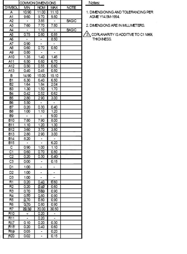
32 7. Physical Dimension Dimension: 15mm(L) x 11mm(W) x 1mm(H) Note: Xmore reserves the right to change non BoM parts without notice. 24
33 25
34 26
35 27
36 8. Flash Management Error Correction Code (ECC) Flash memory cells will deteriorate with use, which might generate random bit errors in the stored data. Thus, Xmore quality microsd Card applies the BCH ECC Algorithm, which can detect and correct errors occur during Read process, ensure data been read correctly, as well as protect data from corruption Wear Leveling NAND Flash devices can only undergo a limited number of program/erase cycles, and in most cases, the flash media are not used evenly. If some area get updated more frequently than others, the lifetime of the device would be reduced significantly. Thus, Wear Leveling technique is applied to extend the lifespan of NAND Flash by evenly distributing write and erase cycles across the media. Xmore quality provides advanced Wear Leveling algorithm, which can efficiently spread out the flash usage through the whole flash media area. Moreover, by implementing both dynamic and static Wear Leveling algorithms, the life expectancy of the NAND Flash is greatly improved Bad Block Management Bad blocks are blocks that include one or more invalid bits, and their reliability is not guaranteed. Blocks that are identified and marked as bad by the manufacturer are referred to as Initial Bad Blocks. Bad blocks that are developed during the lifespan of the flash are named Later Bad Blocks. Xmore quality microsd Card implements an efficient bad block management algorithm to detect the factory-produced bad blocks and manages any bad blocks that appear with use. This practice further prevents data being stored into bad blocks and improves the data reliability. 28
37 SMART Function SMART, an acronym for Self-Monitoring, Analysis and Reporting Technology, is an special function that allows a memory device to automatically monitor its health. Xmore quality provides a program named SmartInfo Tool to observe Xmore SD and microsd cards. Note that this tool can only support Xmore SD and microsd cards. This tool will display the controller version, flash type, firmware version, endurance life ratio, good block ratio, and so forth. In addition, a warning message will appear under the following 3 conditions: 1. When the life ratio remained is less than 10%, 2. When the amount of abnormal power on is more than 3,500 cycles, and 3. When there are less than 5 usable blocks for replacing bad blocks Auto-Read Refresh Auto-Read Refresh is especially applied on devices that read data mostly but rarely write data, such as GPS. When blocks are continuously read, then the device cannot activate wear leveling since it can only be applied while writing data. Thus, errors will accumulate and become uncorrectable. Accordingly, to avoid errors exceed the amount ECC can correct and blocks turn bad, Xmore quality SD Card firmware will automatically refresh the bit errors when the error number in one block approaches the threshold, ex., 24 bits Data Clone System (DCS) Xmore DCS is a function which minimizes the chance of data lost in the event of sudden power lost. When power lost occurred during writing, there will always be a chance where the data become corrupted. To counter this, Xmore quality firmware will perform extra writing of data to a buffer block. In the event of a sudden power loss, during the next power up, ECC will be checked on the original target block. If ECC was discovered, Xmore quality firmware will copy the same data from the buffer block and replace the corrupted data in the original target block. This will greatly reduce the chance of the corrupted data being used continuously. 29
38 9. Partnumber decoder Code: SDU 008G 1 X Q 2 S 3 8 B 4 016Z Description: Formfactor Capacity Xmore Technologie Group/NAND Grade / Temp. Internal Code Speed BOM 1 Capacity 2 Technologie Group / NAND 3 Grade / Temp. 008G : 8GB Q: Xmore quality MLC I: I-Temp. -40 C ~ + 85 C 016G : 16GB I: Xmore industrial SLC C: C-Temp 0 C ~ +70 C 032G : 32GB P: Xmore professional pslc S: S-Temp -25 C ~ +85 C 064G : 64GB 4 Speed A: non UHS B: Class 10 C: UHS-I CL10 D: UHS-II CL10 E: UHS-III CL10 30
Xmore industrial. microsd Card SLC NAND. microsd Card Xmore XIx8x001Z. Datasheet Version 1.3
 Xmore industrial microsd Card SLC NAND Datasheet Version 1.3 Xmore a brand of GLYN GmbH & Co. KG GLYN GmbH & Co. KG Am Wörtzgarten 8 D-65510 Idstein Revision History Revision Draft Date History 1.0 2015/12/30
Xmore industrial. SD Card SLC NAND. SD Card Xmore XII8A001Z. Datasheet Version 1.3
 Xmore industrial SD Card SLC NAND Datasheet Version 1.3 Xmore a brand of GLYN GmbH & Co. KG GLYN GmbH & Co. KG Am Wörtzgarten 8 D-65510 Idstein Revision History Revision Draft Date History 1.0 2015/03/10
Industrial Solution SD Card 3.0 Specification Preliminary Ver. 1.1
 Industrial Solution SD Card 3.0 Specification Preliminary Ver. 1.1 Contents A. General Description... 3 B. Features... 4 C. Comparison of SD Card... 5 D. Pin Assignment... 6 E. Power Consumption... 8 F.
Industrial. Micro SD Card. Product Data Sheet
 Industrial Micro SD Card Product Data Sheet 1 1. Introduction... 4 1.1. General Description... 4 2. Product Specifications... 5 3. Environmental Specifications... 7 3.1. Environmental Conditions... 7 3.2.
SQFlash Industrial Class 10 Micro SD Card SQFlash Micro SD Card Technical Manual Class 10 (SQF-MSDx1-xM/G-21x)
") SQFlash Micro SD Card Technical Manual Class 10 (SQF-MSDx1-xM/G-21x) REV 0.3 Page 1 of 22 May 4, 2016 CONTENTS 1. Overview... 4 2. Standard Features... 5 3. Additional Features... 6 4. Pin Assignment and
SQFlash Micro SD Card Technical Manual Class 10 (SQF-MSDx1-xM/G-21x) REV 0.3 Page 1 of 22 May 4, 2016 CONTENTS 1. Overview... 4 2. Standard Features... 5 3. Additional Features... 6 4. Pin Assignment and
UMSDXXXGBP Micro-SD 3.0 Memory Card Specification
 Micro-SD 3.0 Memory Card Specification Version 1.1 Revision History Revision History Draft Date Remark 1.0 First Release 2011-03-21 Andre 1.1 Mechanical Drawing updated 2011-07-01 Eric A. General Description
Unity Digital Industrial Solution SLC SD 3.0 Specification
 Unity Digital Industrial Solution SLC SD 3.0 Specification Contents A. General Description...1 B. Features...2 C. Comparison of SD Card...3 D. Block Diagram...4 E. Power Consumption...6 F. Environmental
Micro-SD 3.0 Memory Card. Specification Non-UHS
 NO.1, Qun Yi Rd, Jhunan, Miaoli, Taiwan 350, R.O.C. Tel: 886-37-586-896 Fax: 886-37-587-868 Website: www.phison.com Email: Support@phison.com Phison Electronics Corporation Micro-SD 3.0 Memory Card Specification
SQFlash Industrial SD Card SQFlash SD Card Datasheet (SQF-ISDx1-xG-21x)
") SQFlash SD Card Datasheet (SQF-ISDx1-xG-21x) REV 0.4 Page 1 of 20 Mar. 15, 2016 CONTENTS 1. Overview... 4 2. Standard Features... 5 3. Additional Features... 6 4. Pin Assignment and Block Diagram... 8
SQFlash SD Card Datasheet (SQF-ISDx1-xG-21x) REV 0.4 Page 1 of 20 Mar. 15, 2016 CONTENTS 1. Overview... 4 2. Standard Features... 5 3. Additional Features... 6 4. Pin Assignment and Block Diagram... 8
SQFlash Industrial SD Card SQFlash Technical Manual
 SQFlash Technical Manual REV 0.2 Page 1 of 15 Jul. 9, 2010 CONTENTS 1. Overview... 4 2. Standard Features... 5 3. Additional Features... 6 4. Pin Assignment and Block Diagram... 7 5. Power Consumption...
SLC Commercial and Industrial Secure Digital (SD/SDHC) Card
 Card") SLC Commercial and Industrial Secure Digital (SD/SDHC) Card Engineering Specification Document Number L5ENG00432 Rev. 1.8 No part of this document may be reproduced, stored in a retrieval system, or transmitted
SLC Commercial and Industrial Secure Digital (SD/SDHC) Card Engineering Specification Document Number L5ENG00432 Rev. 1.8 No part of this document may be reproduced, stored in a retrieval system, or transmitted
Industrial Micro SD 3.0
 RoHS Recast Compliant Industrial Micro SD 3.0 microsdhc Product Specifications May 7, 2015 Version 1.4 Apacer Technology Inc. 1F, No.32, Zhongcheng Rd., Tucheng Dist., New Taipei City, Taiwan, R.O.C Tel:
MLC. Secure Digital Memory Card
 MLC Secure Digital Memory Card PHANES-F Series Product Specification MLC Secure Digital High & extended Memory Card Version 01V0 Document No. 100-xPSDH-PFTMB May 2017 APRO CO., LTD. Phone: +88628226-1539
aslc Micro Secure Digital Memory Card
 aslc Micro Secure Digital Memory Card PHANES-F Series Product Specification aslc Micro Secure Digital Memory Card Version 01V0 Document No. 100-xPMSD-PFITMBAS April 2016 APRO CO., LTD. Phone: +88628226-1539
Industrial MicroSD 3.0
 RoHS Recast Compliant Industrial MicroSD 3.0 MicroSDHC Product Specifications (Toshiba 15nm) March 15, 2016 Version 1.5 Apacer Technology Inc. 1F, No.32, Zhongcheng Rd., Tucheng Dist., New Taipei City,
Amtron Technology, Inc. Industrial USB 3.0 Flash Drive UA Series Product Datasheet
 Industrial USB 3.0 Flash Drive UA Series Product Datasheet Revision History Revision Description Date 1.0 Initial release 2016-Jan-14 1.1 Update capacity 2016-May-28 1.2 Update performance 2016-Jul-02
MLC. Micro Secure Digital Memory Card
 MLC Micro Secure Digital Memory Card PHANES-F Series Product Specification MLC Micro Secure Digital Memory Card Version 02V1 Document No. 100-xPMSD-PFITMB MAY 2017 APRO CO., LTD. Phone: +88628226-1539
Integral SD /SDHC Card Specification
 Integral SD /SDHC Card Specification MLC Version 1.3 All rights are strictly reserved. Any portion of this paper shall not be reproduced, copied, or translated to any other forms without permission from
Industrial Micro Secure Digital Memory Card
 Industrial Micro Secure Digital Memory Card PHANES-F Series Product Specification INDUSTRIAL Micro Secure Digital Memory Card Version 01V0 Document No. 100-xPMSD-PFTS November 2016 APRO CO., LTD. Phone:
Industrial Secure Digital Memory Card
 Industrial Secure Digital Memory Card PHANES-F Series Product Specification INDUSTRIAL Secure Digital Memory Card Version 01V0 Document No. 100-WPSDC-PFTS April 2016 APRO CO., LTD. Phone: +88628226-1539
SD 3.0 series (SLC) Customer Approver. Approver. Customer: Customer Part Number: Innodisk Part Number: Model Name: Date:
 Customer Approver. Approver. Customer: Customer Part Number: Innodisk Part Number: Model Name: Date:") SD 3.0 series (SLC) Customer: Customer Part Number: Innodisk Part Number: Innodisk Model Name: Date: Innodisk Approver Customer Approver Table of contents Industrial SD card 3.0 (SLC) LIST OF FIGURES...
SD 3.0 series (SLC) Customer: Customer Part Number: Innodisk Part Number: Innodisk Model Name: Date: Innodisk Approver Customer Approver Table of contents Industrial SD card 3.0 (SLC) LIST OF FIGURES...
256MB / 512MB / 1GB / 2GB
 Description: TEKQ TSD133XXX is a new 133X Super Fast Performance mass-storage system based on innovations in semiconductor technology which designed in advanced SD specification Ver.1.1. It s a special
1GB microsd Memory Card. Description. Features. Placement. Pin Definition. Transcend Information Inc. 1
 Description is a. It is non-volatile, which means no external power is required to retain the information stored on it. Besides, it is also a solid-state device that without moving parts to skip or break
SD series. Customer Approver. Innodisk Approver. Customer: Customer Part Number: Innodisk Part Number: Innodisk Model Name: Date:
 SD series Customer: Customer Part Number: Innodisk Part Number: Innodisk Model Name: Date: Innodisk Approver Customer Approver Table of contents Industrial Micro SD card LIST OF FIGURES... 5 1. PRODUCT
SD 3.0 series (MLC) Customer Approver. Approver. Customer: Customer Part Number: Innodisk Part Number: Model Name: Date:
 Customer Approver. Approver. Customer: Customer Part Number: Innodisk Part Number: Model Name: Date:") SD 3.0 series (MLC) Customer: Customer Part Number: Innodisk Part Number: Innodisk Model Name: Date: Innodisk Approver Customer Approver Table of contents Industrial SD card 3.0 (MLC) LIST OF FIGURES...
SD 3.0 series (MLC) Customer: Customer Part Number: Innodisk Part Number: Innodisk Model Name: Date: Innodisk Approver Customer Approver Table of contents Industrial SD card 3.0 (MLC) LIST OF FIGURES...
InnoDisk Industrial SD Card Datasheet Rev. 1.0
 InnoDisk Industrial SD Card Datasheet Rev. 1.0 1 1.0 Datasheet, September 2010 TABLE OF CONTENTS 1. PRODUCT INTRODUCTION... 7 1.1. OVERVIEW... 7 1.2. PRODUCT PICTURE... 7 1.3. PRODUCT FEATURES... 7 2.
SD 3.0 series (islc) Customer. Approver. Approver. Customer: Customer. Part Number: Innodisk Part Number: Innodisk Model Name: Date:
 Customer. Approver. Approver. Customer: Customer. Part Number: Innodisk Part Number: Innodisk Model Name: Date:") SD 3.0 series (islc) Customer: Customer Part Number: Innodisk Part Number: Innodisk Model Name: Date: Innodisk Approver Customer Approver Table of contents Industrial SD card 3.0 (islc) LIST OF FIGURES...
SD 3.0 series (islc) Customer: Customer Part Number: Innodisk Part Number: Innodisk Model Name: Date: Innodisk Approver Customer Approver Table of contents Industrial SD card 3.0 (islc) LIST OF FIGURES...
Industrial nanousb. SLC series. Customer: Customer Part Number: Innodisk Part Number: Innodisk Model Name: Date: Innodisk Approver.
 SLC series Customer: Customer Part Number: Innodisk Part Number: Innodisk Model Name: Date: Innodisk Approver Customer Approver Table of contents REVISION HISTORY... 3 1. Introduction... 6 2. Features...
SD series. Customer Approver. Innodisk Approver. Customer: Customer Part Number: Innodisk Part Number: Innodisk Model Name: Date:
 SD series Customer: Customer Part Number: Innodisk Part Number: Innodisk Model Name: Date: Innodisk Approver Customer Approver Table of contents Industrial Micro SD card LIST OF FIGURES... 5 1. PRODUCT
Quantum Digital Secure Digital Card
 Quantum Digital Secure Digital Card General Description and Key Features The Secure Digital Industrial Grades provide a high reliable storage media in a very small space. The simplicity of the SD and SPI
Industrial SATA Flash Module. Product Data Sheet
 Industrial SATA Flash Module Product Data Sheet 1 1. Introduction... 5 1.1. General Description... 5 1.2. Block Diagram... 5 2. Product Specifications... 6 3. Environmental Specifications... 7 3.1. Environmental
MiniSD Card Specification
 MiniSD Card Specification Model Name : KI032S3CBS KI032S3CCS KI064S3DAS KI128S3EMS KI256S3EMS KI256S3FMS KI512S3FMS Ver 1.1 07.08.2004 1 Features Capcity:32MB/64MB/128MB/256MB/512MByte Compliant SD Card
SanDisk minisd Card. Product Manual. Version 1.1 Document No November SanDisk Corporation
 SanDisk minisd Card Product Manual Version 1.1 Document No. 80-36-00235 November 2003 SanDisk Corporation Corporate Headquarters 140 Caspian Court Sunnyvale, CA 94089 Phone (408) 542-0500 Fax (408) 542-0503
4~16GB High Capacity microsd Card. Description. Features. Placement. Pin Definition. Transcend Information Inc. 1
 Description Transcend High Capacity microsd Card series are specifically designed to meet the High Capacity, High Definition Audio and Video requirement for the latest Digital Cameras, DV Recorders, Mobile
Product Specification Industrial SD & SDHC Memory Cards HERCULES Series
 ] August 2010 Product Specification Industrial SD & SDHC Memory Cards HERCULES Series Doc-No: 100-WPSDCMD-01V2 This document is for information use only and is subject to change without prior notice. APRO
Industrial Micro SD Card
 RoHS Compliant Industrial Micro SD Card Specifications June 12 th, 2012 Version 1.0 Apacer Technology Inc. 4 th Fl., 75 Hsin Tai Wu Rd., Sec.1, Xizhi, New Taipei City, Taiwan 221 Tel: +886-2-2698-2888
ATP Industrial Grade UHS-I microsdhc Card Specification
 AF4GUDI-WACXM AF8GUDI-WACXM Revision 1.0 ATP Electronics, Inc. Table of Contents Disclaimer... 1 Revision History... 1 1.0 Introduction... 2 1.1 Main Features...2 1.2 Card Images...4 1.3 Capacities...4
USB Flash Drive Engineering Specification
 USB Flash Drive Engineering Specification Document Number: L5ENG00242 Revision: A No part of this document may be reproduced, stored in a retrieval system, or transmitted in any form or by any means, mechanical,
ATP Industrial Grade USB Module Specification
 ATP Industrial Grade USB Module Specification ATP Electronics, Inc. CONTENT Disclaimer... 1 Revision History... 1 1.0 ATP Industrial Grade USB Module Overview... 3 1.1 Product Image... 3 1.2 Capacities...
Integral Industrial 2.5 SATA SSD (PS3109-S9) Specification
 Specification") Integral Industrial 2.5 SATA SSD (PS3109-S9) Specification Pseudo SLC Version 1.9 All rights are strictly reserved. Any portion of this paper shall not be reproduced, copied, or translated to any other
Integral Industrial 2.5 SATA SSD (PS3109-S9) Specification Pseudo SLC Version 1.9 All rights are strictly reserved. Any portion of this paper shall not be reproduced, copied, or translated to any other
B270 Series USB Flash Drive Engineering Specification Document Number: L5ENG00242 Revision: D
 B270 Series USB Flash Drive Engineering Specification Document Number: L5ENG00242 Revision: D 2017 Delkin Devices Inc. 1 Table of Contents 1.0 General Description... 3 1.1 Recommended Temperature Conditions...
Ordering Information: USB Family
 Ordering Information: USB Family Viking High Performance USB Drive Ordering Information Part Number Temp NAND GB Controller Interface NAND VRFUSB2256GACCMTL (0 to +70'c) MLC 256 Hyperstone U8 USB 2.0 TSB
TriFlash with Secure Digital (SD) Interface Product Manual (Preliminary)
 Interface Product Manual (Preliminary)") TriFlash with Secure Digital (SD) Interface Product Manual (Preliminary) CORPORATE HEADQUARTERS 140 Caspian Court Sunnyvale, CA 94089-1000 408-542-0500 FAX: 408-542-0503 URL: http://www.sandisk.com SanDisk
TriFlash with Secure Digital (SD) Interface Product Manual (Preliminary) CORPORATE HEADQUARTERS 140 Caspian Court Sunnyvale, CA 94089-1000 408-542-0500 FAX: 408-542-0503 URL: http://www.sandisk.com SanDisk
Industrial M SATA Drive. Product Data Sheet
 Industrial M.2 2242 SATA Drive Product Data Sheet 1 1. Introduction...4 1.1. General Description... 4 1.2. Block Diagram... 4 2. Product Specifications...5 3. Environmental Specifications...6 3.1. Environmental
Customer: Customer. Part Number: Innodisk. Part Number: Innodisk. Model Name: Date: Customer. Innodisk. Approver. Approver
 Customer: Customer Part Number: Innodisk Part Number: Innodisk Model Name: Date: Innodisk Approver Customer Approver Table of contents TABLE OF CONTENTS... 2 REVISION HISTORY... 3 LIST OF FIGURES... 4
SATA III 6Gb/S 2.5 SSD Industrial Temp AQS-I25S I Series. Advantech. Industrial Temperature. Datasheet. Rev
 Advantech erature Datasheet Rev. 3.0 2015-09-22 1 Features SATA III 6Gb/s SSD Advanced Global Wear-Leveling and Block management for reliability I Series Offers industrial level SSD that sustains and extends
Xmore professional SSD 2,5. pslc NAND. SSD 2,5 Xmore XPC8B021Z. Solid State Drive SATAIII. Datasheet Version 1.1
 Xmore professional SSD 2,5 Solid State Drive SATAIII pslc NAND Datasheet Version 1.1 Xmore a brand of GLYN GmbH & Co. KG GLYN GmbH & Co. KG Am Wörtzgarten 8 D-65510 Idstein Revision History Revision Draft
UD info Corp. Industrial SATA Solid State Drive HF3-25UD(8-ch) Series Product DataSheet
 Series Product DataSheet") UD info Corp. Industrial SATA Solid State Drive HF3-25UD(8-ch) Series Product DataSheet UD info CORP. TEL: +886-2-7713-6050 FAX: +886-2-8511-3151 E-mail: sales@udinfo.com.tw 1. Introduction... 5 1.1. General
UD info Corp. Industrial SATA Solid State Drive HF3-25UD(8-ch) Series Product DataSheet UD info CORP. TEL: +886-2-7713-6050 FAX: +886-2-8511-3151 E-mail: sales@udinfo.com.tw 1. Introduction... 5 1.1. General
Datasheet. Embedded Storage Solutions. Industrial. SATA III 2.5 Solid State Drive. SED2FIV Series CSXXXXXRC-XX10XXXX. 22 Aug 2017 V1.
 Embedded Storage Solutions Industrial SATA III 2.5 Solid State Drive SED2FIV Series CSXXXXXRC-XX10XXXX 1 Table of Contents 1. Product Description... 4 1.1. Product Overview... 4 1.2. Product Features...
UD info Corp. Industrial M SATA Drive M2S-80UD Series Product DataSheet
 UD info Corp. Industrial M.2 2280 SATA Drive M2S-80UD Series Product DataSheet UD info CORP. TEL: +886-2-7713-6050 FAX: +886-2-8511-3151 E-mail: sales@udinfo.com.tw 1. Introduction... 5 1.1. General Description...
Rev GB Extended Capacity Secure Digital Card. Description. Features. Placement. Pin Definition. Transcend Information Inc.
 Description Transcend secured digital extended capacity Card series are specifically designed to meet the High Capacity, High Definition Audio and Full HD Video requirement for the latest Digital Cameras,
Advantech. AQS-I42N I Series. Semi-Industrial Temperature. Datasheet. SATA III 6Gb/s M.2 SSD Semi-Industrial Temp AQS-I42N I series
 Advantech AQS-I42N I Series erature Datasheet Rev. 2.0 2015-09-13 1 AQS-I42N I Series Features SATA III 6Gb/s M.2 SSD I Series Offers industrial level M.2 SSD that sustains and extends system lifecycle
SD Series Customer: Customer Part Number: Innodisk Part Number: Innodisk Model Name: Date:
 SD Series Customer: Customer Part Number: Innodisk Part Number: Innodisk Model Name: Date: 1 Rev 1.9 TPS, Sep, 2013 Table of contents 1. PRODUCT INTRODUCTION... 7 1.1. OVERVIEW... 7 1.2. PRODUCT PICTURE...
SD Series. Customer. InnoDisk. Approver. Approver. Customer: Customer. Part Number: InnoDisk. Part Number: InnoDisk.
 SD Series Customer: Customer Part Number: InnoDisk Part Number: InnoDisk Model Name: Date: InnoDisk Approver Customer Approver Table of contents 1. PRODUCT INTRODUCTION... 7 1.1. OVERVIEW... 7 1.2. PRODUCT
Customer: Customer. Part Number: Innodisk. Part Number: Innodisk. Model Name: Date: Customer. Innodisk. Approver. Approver
 Customer: Customer Part Number: Innodisk Part Number: Innodisk Model Name: Date: Innodisk Approver Customer Approver Table of contents TABLE OF CONTENTS... 2 LIST OF FIGURES... 4 LIST OF TABLES... 5 1.
Integral Industrial msata(ps3109-s9) Specification
 Specification") Integral Industrial msata(ps3109-s9) Specification (Pseudo SLC) Version 2.0 All rights are strictly reserved. Any portion of this paper shall not be reproduced, copied, or translated to any other forms
Integral Industrial msata(ps3109-s9) Specification (Pseudo SLC) Version 2.0 All rights are strictly reserved. Any portion of this paper shall not be reproduced, copied, or translated to any other forms
1MG3-P Series. Customer Approver. Innodisk Approver. Customer: Customer Part Number: Innodisk Part Number: Innodisk Model Name: Date:
 1MG3-P Series Customer: Customer Part Number: Innodisk Part Number: Innodisk Model Name: Date: Innodisk Approver Customer Approver Table of contents 2.5 PATA SSD 1MG3-P LIST OF FIGURES... 6 1. PRODUCT
MIRA M2320 series Halfslim SSD Specification. v0.1
 1 MIRA M2320 series Halfslim SSD Specification v0.1 2 Revision History Date Version Changes compared to previous issue Jun 1 nd, 2012 0.1 - Initial Release 3 Table of Contents Introduction:... 4 Main Feature:...
SLC. mini SATA III SSD. PHANES-K Series. APRO Industrial SATA-III msata SSD. Document No. : 100-xBMSM-PKCTC. Version No. : 01V0
 SLC mini SATA III SSD PHANES-K Series APRO Industrial SATA-III msata SSD Document No. : 100-xBMSM-PKCTC Version No. : 01V0 Date : September 2018 Product Features Product Features Flash IC TOSHIBA NAND
SOLDERABLE MEMORY MODULE (SMM)
") SOLDERABLE MEMORY MODULE (SMM) DATA SHEET ABSTRACT The Solderable Memory Module (SMM) is an alternative to SD/MMC cards for use in industrial and medical embedded systems. The module combines all the advantages
SOLDERABLE MEMORY MODULE (SMM) DATA SHEET ABSTRACT The Solderable Memory Module (SMM) is an alternative to SD/MMC cards for use in industrial and medical embedded systems. The module combines all the advantages
Xmore professional SSD 2,5. pslc NAND. SSD 2,5 Xmore XPI8B021Z. Solid State Drive SATAIII. Datasheet Version 1.0
 Xmore professional SSD 2,5 Solid State Drive SATAIII pslc NAND Datasheet Version 1.0 Xmore a brand of GLYN GmbH & Co. KG GLYN GmbH & Co. KG Am Wörtzgarten 8 D-65510 Idstein Revision History Revision Draft
SED2FIII-MP Series. Embedded Storage Solutions. SATA III 2.5 Solid State Drive. SED2FIII Series Datasheet. Enterprise Grade CSXXXXXXB-XXXXB3XX
 Embedded Storage Solutions Enterprise Grade SATA III 2.5 Solid State Drive SED2FIII-MP Series CSXXXXXXB-XXXXB3XX 1 Table of Contents 1. Product Description... 4 1.1. Product Overview... 4 1.2. Product
Datasheet. Embedded Storage. Solutions. Embedded SSD. SATAIII msata (mini PCIe) MSS4FIII Series
 MSS4FIII Series") Embedded Storage Embedded SSD SATAIII msata (mini PCIe) MSS4FIII Series Solutions V1.0 1 Table of Contents 1. Product Description... 4 1.1. Product Overview... 4 1.2. Product Features... 4 1.3. System
Embedded Storage Embedded SSD SATAIII msata (mini PCIe) MSS4FIII Series Solutions V1.0 1 Table of Contents 1. Product Description... 4 1.1. Product Overview... 4 1.2. Product Features... 4 1.3. System
Datasheet. Embedded Storage Solutions. Industrial. SATA III 2.5 Solid State Drive. SED2FIV Series CSXXXXXRC-XX09XXXX. 04 Jul 2016 V1.
 Embedded Storage Solutions Industrial SATA III 2.5 Solid State Drive SED2FIV Series CSXXXXXRC-XX09XXXX 1 Table of Contents 1. Product Description... 4 1.1. Product Overview... 4 1.2. Product Features...
Datasheet. Embedded Storage Solutions. Industrial. SATA III 2.5 Solid State Drive. SED2FV Series. V Aug
 Embedded Storage Solutions Industrial SATA III 2.5 Solid State Drive SED2FV Series 1 Table of Contents Product Description... 4 1.1. Product Overview... 4 1.2. Product Features... 4 1.3. Specifications...
Customer: Customer. Part Number: Innodisk. Part Number: Innodisk. Model Name: Date: Customer. Innodisk. Approver. Approver
 Customer: Customer Part Number: Innodisk Part Number: Innodisk Model Name: Date: Innodisk Approver Customer Approver Table of contents TABLE OF CONTENTS... 2 LIST OF FIGURES... 4 LIST OF TABLES... 5 1.
California PC FLASH ATA PC Card PCMCIA Full Specifications
 CaliforniaPC.com California Peripherals & Components, Inc. WorldWide Supplier of Computer Hardware & Software Any Where. Any Temperature.* California PC FLASH ATA PCMCIA Full Specifications Industrial
Virtium eusb Flash Module. Product Specification VUS 200 Series
 Virtium eusb Flash Module Product Specification VUS 200 Series 1.0 Introduction Virtium s VUS 200 Series eusb flash module provides rugged storage for single board computers and industrial systems. Virtium
Datasheet. Embedded Storage Solutions. Industrial. SATA III 2.5 Solid State Drive. SED2FV Series. V Aug
 Embedded Storage Solutions Industrial SATA III 2.5 Solid State Drive SED2FV Series 1 Table of Contents Product Description... 4 1.1. Product Overview... 4 1.2. Product Features... 4 1.3. Specifications...
3ME3 Series. Customer Approver. Innodisk Approver. Customer: Customer Part Number: Innodisk Part Number: Innodisk Model Name: Date:
 3ME3 Series Customer: Customer Part Number: Innodisk Part Number: Innodisk Model Name: Date: Innodisk Approver Customer Approver Table of contents msata 3ME3 LIST OF FIGURES... 6 1. PRODUCT OVERVIEW...
3SE4 Series. Customer Approver. Innodisk Approver. Customer: Customer Part Number: Innodisk Part Number: Innodisk Model Name: Date:
 3SE4 Series Customer: Customer Part Number: Innodisk Part Number: Innodisk Model Name: Date: Innodisk Approver Customer Approver Table of contents msata 3SE4 LIST OF FIGURES... 6 1. PRODUCT OVERVIEW...
3MG-P Series. Customer Approver. Approver. Customer: Customer Part Number: Innodisk Part Number: Model Name: Date:
 3MG-P Series Customer: Customer Part Number: Innodisk Part Number: Innodisk Model Name: Date: Innodisk Approver Customer Approver Table of contents SATA Slim 3MG-P LIST OF FIGURES... 6 1. PRODUCT OVERVIEW...
3ME4 Series. Customer Approver. Innodisk Approver. Customer: Customer Part Number: Innodisk Part Number: Innodisk Model Name: Date:
 3ME4 Series Customer: Customer Part Number: Innodisk Part Number: Innodisk Model Name: Date: Innodisk Approver Customer Approver Table of contents msata 3ME4 LIST OF FIGURES... 6 1. PRODUCT OVERVIEW...
1SR-P Series. Customer Approver. Innodisk Approver. Customer: Customer Part Number: Innodisk Part Number: Innodisk Model Name: Date:
 1SR-P Series Customer: Customer Part Number: Innodisk Part Number: Innodisk Model Name: Date: Innodisk Approver Customer Approver Table of Contents 2.5 PATA SSD 1SR-P LIST OF FIGURES... 6 1. PRODUCT OVERVIEW...
Industrial M Specification SATA III (6Gb/s)
") Industrial M.2 2242 Specification SATA III (6Gb/s) Version 1.1 Revision History Revision History Draft Date 1.0 First release 2014/07/11 1.1 Update TBW data 2015/02/18 Product Overview Capacity 4GB up
Industrial M.2 2242 Specification SATA III (6Gb/s) Version 1.1 Revision History Revision History Draft Date 1.0 First release 2014/07/11 1.1 Update TBW data 2015/02/18 Product Overview Capacity 4GB up
3SE-P Series. Customer Approver. Approver. Customer: Customer Part Number: Innodisk Part Number: Model Name: Date:
 3SE-P Series Customer: Customer Part Number: Innodisk Part Number: Innodisk Model Name: Date: Innodisk Approver Customer Approver Table of contents LIST OF FIGURES... 6 1. PRODUCT OVERVIEW... 7 1.1 INTRODUCTION
2.5-Inch SATA SSD PSSDS27Txxx6
 DMS Celerity 2.5 SSD Datasheet 2.5-Inch SATA SSD PSSDS27Txxx6 Features: SATA 3.1 Compliant, SATA 6.0Gb/s with 3Gb/s and 1.5Gb/s support ATA modes supported PIO modes 3 and 4 Multiword DMA modes 0, 1, 2
Xmore quality Datasheet Version 1.0
 Xmore quality CFAST TM MLC NAND Datasheet Version 1.0 Xmore a brand of GLYN GmbH & Co. KG GLYN GmbH & Co. KG Am Wörtzgarten 8 D-65510 Idstein Revision History Revision Draft Date History 1.0 2017/02/21
1ME Series. Customer Approver. Innodisk Approver. Customer: Customer Part Number: Innodisk Part Number: Innodisk Model Name: Date:
 1ME Series Customer: Customer Part Number: Innodisk Part Number: Innodisk Model Name: Date: Innodisk Approver Customer Approver Table of contents 2.5 PATA SSD 1ME LIST OF FIGURES... 6 1. PRODUCT OVERVIEW...
3ME4 Series. Customer Approver. Innodisk Approver. Customer: Customer Part Number: Innodisk Part Number: Innodisk Model Name: Date:
 3ME4 Series Customer: Customer Part Number: Innodisk Part Number: Innodisk Model Name: Date: Innodisk Approver Customer Approver Table of contents msata mini 3ME4 LIST OF FIGURES... 6 1. PRODUCT OVERVIEW...
SMART MODULAR XL MLC SD Card 4 GB 32 GB SDHC Memory Cards 64 GB SDXC Memory Cards
 SMART MODULAR XL MLC SD Card 4 GB 32 GB SDHC Memory Cards 64 GB SDXC Memory Cards SH9SDxxxGPHExMI01, Rev A www.smartm.com REVISION HISTORY Date Revision Section(s) Description A All Initial release. ESD
3ME3 Series. Customer Approver. Innodisk Approver. Customer: Customer Part Number: Innodisk Part Number: Innodisk Model Name: Date:
 3ME3 Series Customer: Customer Part Number: Innodisk Part Number: Innodisk Model Name: Date: Innodisk Approver Customer Approver Table of contents SATA Slim 3ME3 LIST OF FIGURES... 6 1. PRODUCT OVERVIEW...
HyperDisk SOLID STATE DISK
 SOLID STATE DISK NAND Flash-based 2.5 SATA Standard Type Product Data sheet Preliminary Mar 2008 Storage Tecnologies Ltd INFORMATION IN THIS DOCUMENT IS PROVIDED IN RELATION TO HYPERDISK PRODUCTS, AND
3ME4 Series. Customer: Customer Part Number: Innodisk Part Number: Innodisk Model Name: Date: Innodisk Approver. Customer Approver
 3ME4 Series Customer: Customer Part Number: Innodisk Part Number: Innodisk Model Name: Date: Innodisk Approver Customer Approver Table of Contents Slim SSD 3ME4 LIST OF FIGURES... 6 1. PRODUCT OVERVIEW...
aslc Mini SATA III Flash Module PHANES-HR Series Product Specification APRO aslc MINI SATA III FLASH MODULE
 aslc Mini SATA III Flash Module PHANES-HR Series Product Specification APRO aslc MINI SATA III FLASH MODULE Version 01V1 Document No. 100-xBMSR-PHCTMBAS June 2016 APRO CO., LTD. Phone: +88628226-1539 Fax:
3ME3 Series. Customer Approver. Innodisk Approver. Customer: Customer Part Number: Innodisk Part Number: Innodisk Model Name: Date:
 3ME3 Series Customer: Customer Part Number: Innodisk Part Number: Innodisk Model Name: Date: Innodisk Approver Customer Approver Table of contents msata mini 3ME3 LIST OF FIGURES... 6 1. PRODUCT OVERVIEW...
3MG-P Series. Customer Approver. Innodisk Approver. Customer: Customer Part Number: Innodisk Part Number: Innodisk Model Name: Date:
 3MG-P Series Customer: Customer Part Number: Innodisk Part Number: Innodisk Model Name: Date: Innodisk Approver Customer Approver Table of contents LIST OF FIGURES... 6 1. PRODUCT OVERVIEW... 7 1.1 INTRODUCTION
2.5-Inch SATA SSD -7.0mm PSSDS27xxx3
 2.5-Inch SATA SSD -7.0mm PSSDS27xxx3 Features: Ultra-efficient Block Management & Wear Leveling Advanced Read Disturb Management Intelligent Recycling for advanced free space management RoHS-compliant
Datasheet. Embedded Storage Solutions SATA EDOM SDM0CII-V(T/M) CDXXXXGRK-XXXXXXXX. V Aug
 CDXXXXGRK-XXXXXXXX. V Aug") Embedded Storage Solutions SATA EDOM SDM0CII-V(T/M) CDXXXXGRK-XXXXXXXX 1 Revision History Revision Date Description Remark V 1.0 2014/7/29 First Release V 1.1 2015/9/1 Revised Ordering Information V 1.2
Embedded Storage Solutions SATA EDOM SDM0CII-V(T/M) CDXXXXGRK-XXXXXXXX 1 Revision History Revision Date Description Remark V 1.0 2014/7/29 First Release V 1.1 2015/9/1 Revised Ordering Information V 1.2
SATA III MLC CFast Card
 SATA III MLC CFast Card PHANES-C Series Product Specification APRO MLC SATA III CFast Card Version 01V0 Document No. 100-xPCFA-JGTM April 2015 APRO CO., LTD. Phone: +88628226-1539 Fax: +88628226-1389 This
NAND32GW3F4A. 32-Gbit (4 x 8 Gbits), two Chip Enable, 4224-byte page, 3 V supply, multiplane architecture, SLC NAND flash memories.
, two Chip Enable, 4224-byte page, 3 V supply, multiplane architecture, SLC NAND flash memories.") 32-Gbit (4 x 8 Gbits), two Chip Enable, 4224-byte page, 3 V supply, multiplane architecture, SLC NAND flash memories Features High-density SLC NAND flash memory 32 Gbits of memory array 1 Gbit of spare
32-Gbit (4 x 8 Gbits), two Chip Enable, 4224-byte page, 3 V supply, multiplane architecture, SLC NAND flash memories Features High-density SLC NAND flash memory 32 Gbits of memory array 1 Gbit of spare
Industrial µssd Specification SATA III (6Gb/s)
") Industrial µssd Specification SATA III (6Gb/s) Version 1.4 Revision History Revision History Draft Date 1.0 First release 2014/07/11 1.1 Update TBW data 2015/02/18 1.2 Added Current Draw by Voltage Rail
Industrial µssd Specification SATA III (6Gb/s) Version 1.4 Revision History Revision History Draft Date 1.0 First release 2014/07/11 1.1 Update TBW data 2015/02/18 1.2 Added Current Draw by Voltage Rail
3SE4 Series. Customer Approver. Innodisk Approver. Customer: Customer Part Number: Innodisk Part Number: Innodisk Model Name: Date:
 3SE4 Series Customer: Customer Part Number: Innodisk Part Number: Innodisk Model Name: Date: Innodisk Approver Customer Approver Table of contents LIST OF FIGURES... 6 1. PRODUCT OVERVIEW... 7 1.1 INTRODUCTION
EPTDM Features SATA III 6Gb/s msata SSD
 EPTDM Features SATA III 6Gb/s msata SSD Transcend EPTDM series are msata Solid State Drives (SSDs) with high performance and quality Flash Memory assembled on a printed circuit board. These devices feature
93C76/86. 8K/16K 5.0V Microwire Serial EEPROM FEATURES DESCRIPTION PACKAGE TYPES BLOCK DIAGRAM
 8K/16K 5.0V Microwire Serial EEPROM FEATURES PACKAGE TYPES Single 5.0V supply Low power CMOS technology - 1 ma active current typical ORG pin selectable memory configuration 1024 x 8- or 512 x 16-bit organization
3MG-P Series. Customer Approver. Innodisk Approver. Customer: Customer Part Number: Innodisk Part Number: Innodisk Model Name: Date:
 3MG-P Series Customer: Customer Part Number: Innodisk Part Number: Innodisk Model Name: Date: Innodisk Approver Customer Approver Table of contents msata 3MG-P LIST OF FIGURES... 6 1. PRODUCT OVERVIEW...
3ME2 Series. Customer Approver. Innodisk Approver. Customer: Customer Part Number: Innodisk Part Number: Innodisk Model Name: Date:
 3ME2 Series Customer: Customer Part Number: Innodisk Part Number: Innodisk Model Name: Date: Innodisk Approver Customer Approver Table of contents LIST OF FIGURES... 6 1. PRODUCT OVERVIEW... 7 1.1 INTRODUCTION
3ME Series. Customer Approver. Approver. Customer: Customer Part Number: Innodisk Part Number: Model Name: Date:
 3ME Series Customer: Customer Part Number: Innodisk Part Number: Innodisk Model Name: Date: Innodisk Approver Customer Approver Table of contents 2.5 SATA SSD 3ME LIST OF FIGURES... 6 1. PRODUCT OVERVIEW...
Serial ATA Flash Drive
 RoHS Compliant Serial ATA Flash Drive msata H1-M Product Specifications November 20 th, 2014 Version 1.3 Apacer Technology Inc. 1F, No.32, Zhongcheng Rd., Tucheng Dist., New Taipei City, Taiwan, R.O.C
MLC. Mini SATA III Flash Module (msata Module) PHANES-HR Series. Product Specification. APRO MLC mini SATA III flash module
 PHANES-HR Series. Product Specification. APRO MLC mini SATA III flash module") MLC Mini SATA III Flash Module (msata Module) PHANES-HR Series Product Specification APRO MLC mini SATA III flash module Supports DDR-III SDRAM Cache Version 01V0 Document No. 100-XBMSR-PHCTMB April 2016
MLC Mini SATA III Flash Module (msata Module) PHANES-HR Series Product Specification APRO MLC mini SATA III flash module Supports DDR-III SDRAM Cache Version 01V0 Document No. 100-XBMSR-PHCTMB April 2016