890 Quickstart Manual
|
|
|
- Alice Lewis
- 5 years ago
- Views:
Transcription

1 890 Quickstart Manual AC890PX AC Drive HA471665U000 Issue 2 (ISO A4) HA471665U001 Issue 2 (American Quarto) Copyright 2008 Parker SSD Drives, a division of Parker Hannifin Ltd. All rights strictly reserved. No part of this document may be stored in a retrieval system, or transmitted in any form or by any means to persons not employed by a Parker SSD Drives company without written permission from Parker SSD Drives, a division of Parker Hannifin Ltd. Although every effort has been taken to ensure the accuracy of this document it may be necessary, without notice, to make amendments or correct omissions. Parker SSD Drives cannot accept responsibility for damage, injury, or expenses resulting therefrom. WARRANTY Parker SSD Drives warrants the goods against defects in design, materials and workmanship for the period of 12 months from the date of delivery on the terms detailed in Parker SSD Drives Standard Conditions of Sale IA Parker SSD Drives reserves the right to change the content and product specification without notice.
2 C o n t e n t s Safety... 3 Hazards to Personnel Application Risk 3 3 Risk Assessment 4 Accessibility 4 Protective Insulation 4 RCDs 4 Introduction... 5 About this QuickStart 5 Overview... 6 AC890PX (top wire entry) 6 AC890PX (bottom wire entry) 7 Installation... 8 Mounting Dimensions 8 Air Flow 8 Environmental Conditions 8 AC890PX Power Connections... 9 Components : Top Wire Entry 9 Wiring Diagram : Top Wire Entry 10 Components : Bottom Wire Entry 11 Wiring Diagram : Bottom Wire Entry Auxiliary Transformer Taps (C) AC890PX Control Connections AC890PX Feedback Connections AC890PX Feedback Connections Drive Start-up Before Applying Power : 16 Drive Set-up Motor Data 16 Quick Setup Parameters 17 Autotune 18 Running in Local 19 Running in Remote 19 Appendix A: Using the 6901 Keypad The Menu Structure 21 Appendix B: Analog and Digital I/O Appendix C: Electrical Ratings Page Page 2

3 Safety IMPORTANT: Please read this information BEFORE installing the equipment. Hazards to Personnel WARNING! This equipment can endanger life through rotating machinery and high voltages. Failure to observe the following will constitute an ELECTRICAL SHOCK HAZARD. Metal parts may reach a temperature of 70 degrees Centrigrade in operation. Before working on the equipment, ensure isolation of the mains supply from terminals L1, L2 and L3. Allow at least 10 minutes for the drive's capacitors to discharge to safe voltage levels (<50V). Use the specified meter capable of measuring up to 1000V dc & ac rms to confirm that less than 50V is present between all power terminals and between power terminals and earth. Application Risk The specifications, processes and circuitry described herein are for guidance only and may need to be adapted to the user's specific application. Parker SSD Drives does not guarantee the suitability of the equipment described in the Manual for individual applications. Page 3
4 Risk Assessment Under fault conditions, power loss or other operating conditions not intended, the equipment may not operate as specified. In particular: The motor speed may not be controlled The direction of rotation of the motor may not be controlled The motor may be energised Accessibility All live power terminals are IP20 rated only, accessible with the enclosure door open. Protective Insulation All control and signal terminals are SELV, i.e. protected by double insulation. Ensure all wiring is rated for the highest system voltage. NOTE Thermal sensors contained within the motor must be single/basic insulated. All exposed metalwork in the Drive is protected by basic insulation and bonding to a safety earth. RCDs Not recommended for use with this product. Where their use is mandatory, use only Type B RCDs (EN61009). Caution This is a product of the restricted sales distribution class according to IEC It is designated as professional equipment as defined in EN Permission of the supply authority shall be obtained before connection to the low voltage supply. Page 4
5 Introduction The AC890PX is designed to control 3-phase induction or permanent magnet AC motors, or to be used as an active front-end. Remote control using configurable analogue and digital inputs and outputs. Local control using the Keypad. Use the Drive System Explorer Configuration Tool (DSE 890) to give access to parameters, diagnostic messages, trip settings and application programming. Fit Options to the unit to give serial communications and closed loop speed control. IMPORTANT: Motors used must be suitable for Inverter duty. About this QuickStart This QuickStart will: Familiarise you with the terminals and operation of the unit. Provide basic* installation details and a quick set-up procedure. Show you how to Autotune the drive and start the motor. * Because the 890 is a system product and we have no knowledge of your application, we detail the quickest way to power-up the drive using a simple earthing scheme with minimal control wiring. Refer to the full Engineering Reference Manual for items not covered in this QuickStart. Provided with every 890 unit is a : Quickstart Compact disk containing the Engineering Reference Manual and DSE Lite Configuration Tool Keypad Customer-ordered Options This QuickStart assumes that: You are a qualified technician with experience of installing this type of equipment. You are familiar with the relevant standards and Local Electric Codes (which take precedence). You have read and understood the Safety information provided at the front of this QuickStart. You realise that this guide contains only basic information and that you may need to refer to the Engineering Reference Manual to complete your installation. Page 5
")
6 Overview AC890PX (top wire entry) Page 6

")
7 AC890PX (bottom wire entry) Page 7
8 Installation For European installations and countries with EMC legislation refer to the 890 Engineering Reference Manual, Appendix C. Mounting Dimensions With any tall unit such as the AC890PX drive, it is advisable to secure the top to prevent it tipping over. AIR CLEARANCE AIR CLEARANCE D During operation it must stand vertically on a solid, flat, horizontal, normally cool, nonflammable surface. The bottom wire entry version of the drive will sit on a plinth (allowing the cables to be fed through the bottom of the drive). In this case, also secure the drive to the plinth. 890PX 890PX Refer to Chapter 3: Installation Drawings in the Engineering Reference manual for more information. Air Flow It is important that the top vent is properly fitted to assure that the exhaust air is not recirculated. A It is important that air heated by other items should not affect the inlet temperature to the drive s fans. B C Maximum Weight kg/lbs A B C D 132kW 600lbs (272kg) 200kW 600lbs (272kg) 2024mm 500mm 620mm 280mm 315kW 732lbs (333kg) (79.7") (19.7") (24.4") (11.0") 400kW 790lbs (360kg) Environmental Conditions Operating ambient temperature 0 C to 40 C (32 F to 104 F) Enclosure rating IP4X UL(cUL) Enclosed Type 1 Atmosphere Dust free, non flammable, non-corrosive, <85% humidity, non-condensing Page 8

9 AC890PX Power Connections Components : Top Wire Entry A Isolator B C D Control Module/Control Terminals Auxiliary Transformer Set the transformer taps - see page 13. Motor/Output Connections E Protective Earth/Ground F G H I J Internal Brake Resistor Thermal Overload Protection User Blower Motor Thermal Overload Protection Auxiliary Supply Protection - Circuit Breaker (primary) Auxiliary Supply Protection - Semiconductor Fuse (secondary) External Brake Resistor Terminal Block K 3-Phase Connections Page 9
10 Wiring Diagram : Top Wire Entry Permanent Earthing Each unit must be permanently earthed according to EN For permanent earthing, EN states that: A cross-section conductor of at least 10mm² copper or 16mm 2 aluminium is required. Conductors must be sized in accordance with Local Wiring Regulations which always take precedence. As a guide, refer to the Input Current for the drive given in the Electrical Ratings tables. Page 10

11 Components : Bottom Wire Entry A Isolator B C D Control Module/Control Terminals Auxiliary Transformer Set the transformer taps - see page 13. Motor/Output Connections E Protective Earth/Ground F G H I J Internal Brake Resistor Thermal Overload Protection User Blower Motor Thermal Overload Protection Auxiliary Supply Protection - Circuit Breaker (primary) Auxiliary Supply Protection - Semiconductor Fuse (secondary) External Brake Resistor Terminal Block K 3-Phase Connections Permanent Earthing Each unit must be permanently earthed according to EN For permanent earthing, EN states that: A cross-section conductor of at least 10mm² copper or 16mm 2 aluminium is required. Conductors must be sized in accordance with Local Wiring Regulations which always take precedence. As a guide, refer to the Input Current for the drive given in the Electrical Ratings tables. Page 11
12 Wiring Diagram : Bottom Wire Entry Page 12

13 Auxiliary Transformer Taps (C) The transformer is tapped for no connection, i.e. 0V - PARK when it leaves the factory and the drive will not operate. Either a low voltage or high voltage transformer option is fitted to the drive. Match the auxiliary transformer tap to the drive's nominal supply voltage. For example, connect the taps to 0V and 400V for a nominal supply voltage of 400Vac. The transformer supplies a constant 30Vac to the Control Module, internal fans etc. It is protected by a 40A semi-conductor fuse Auxiliary Transformer 40A Semi-Conductor Fuse Page 13

14 AC890PX Control Connections A Speed Reference Connect a 10kΩ potentiometer at terminal block X12 (Analog I/P 3) High (CW): terminal X12/08 Wiper: terminal X12/04 Low (CCW): terminal X12/01 Connect the shield to earth/ground on the drive's metal framework. OR External 2-wire speed reference between terminals X12/01(-) and X12/04(+) Connect the shield to earth ground on the drive's metal framework. The control terminals will accept a single wire of size 1.5mm 2 /16AWG. For two wires per terminal, use smaller gauge wire such as 0.5mm 2 /22AWG. B Sequencing Connect volt-free contacts as required RUN (maintained contact) terminal X14/03 and terminal X15/02 C Thermistor Connect motor thermal switch or thermistor to terminals X16/08 & X16/09. Drive will trip when the thermal switch opens, or when the thermistor resistance exceeds 4kΩ maximum (PTC Type A : IEC Part 2) If the motor does not have a protective device (thermistor), jumper these terminals. The drive needs the thermistor inputs connected for it to run. Analog SPEED FEEDBACK 10V = ±100% speed at terminal X12/0 6 TORQUE FEEDBACK 10V = ±200% torque at terminal X12/07 ANALOG COMMON 0V at terminal X12/0 1 Digital DRIVE HEALTH Relay dry contact (24V rated) at terminal X14/01 and terminal X14/02 RUNNING 24V sourcing output at terminal X15/08 ZERO SPEED 24V sourcing output at terminal X15/09 DIGITAL COMMON 0V at terminal X14/04 This is a basic connection diagram. For more detailed information on control connections, refer to Appendix B. Page 14

15 AC890PX Feedback Connections This section is only for closed loop vector and induction servo applications. Skip this page if there is no encoder or resolver mounted on the motor. Incremental Pulse Encoders The default settings for the drive are for 2048 line, quadrature, incremental pulse encoders with differential outputs operating from a 10VDC supply. Z channel (Marker pulse) connections are not necessary for running the drive, but inputs are provided for positioning and servo applications. The supply voltage to the encoder is set in the Quick Setup menu. Range 10 VDC to 20 VDC Use the Keypad to set the following options: Supply Voltage - PULSE ENC VOLTS Number of lines per revolution - ENCODER LINES parameter * Encoder direction - ENCODER INVERT OPTION F Terminal Block 01 Shield 02 Supply 03 Supply + 04 Channel Z/ 05 Channel Z 06 Channel B/ 07 Channel B 08 Channel A/ 09 Channel A * Used to match the encoder direction to the motor direction. When TRUE, changes the sign of the measured speed and the direction of the position count. It is necessary to set up this parameter when in CLOSED-LOOP VEC mode, as the encoder direction must be correct for this mode to operate. Using other types of encoders requires the 890 DSE Configuration Tool and the setting of other parameters. Refer to the AC890PX Engineering Reference Manual for details of these parameters. OPTION F Use 3-pair or 4-pair, individually shielded encoder cable, Belden model 8777 or equivalent. Page 15
16 Drive Start-up Before Applying Power : Read the Safety section at the front of the QuickStart. Ensure that all local electric codes are met. Check for damage to equipment. Check for loose ends, clippings, filings, drilling swarf etc. lodged in the drive and system. Check all external wiring circuits of the system - power, control, motor and earth connections. Ensure that unexpected rotation of the motor in either direction will not result in damage, bodily harm or injury. Disconnect the load from the motor shaft, if possible. Check the state of the Motor Thermistor and Brake Resistor connectors. Check external run contacts are open. Check external speed setpoints are all at zero. Ensure that nobody is working on another part of the system which will be affected by powering up. Ensure that other equipment will not be adversely affected by powering up. Check motor stator connections are correctly wired for Star or Delta as necessary for drive output voltage. If all connections have been checked, it is time to POWER-UP the drive Drive Set-up Appendix A contains information about the Keypad menus and parameter names. Motor Data Before attempting to set up the drive, you will need some motor information. This is found on the motor nameplate. The information you will need is listed below: Base Volts Base frequency Base RPM Full load amps No load amps (mag current) Connection (star or delta) Page 16
17 Quick Setup Parameters The following is a list of the Quick Setup parameters you must check before starting the drive. Set only the ones marked with x in the table below, under the intended mode of operation. V/Hz SV Vector PMAC Control Mode Select the intended operating mode x x x x Max Speed Motor RPM at full process speed x x x x V/F shape Usually Linear. Choose fan curve only for fans x Motor Current Motor full load current from motor nameplate x x x Motor Base Freq Motor nameplate frequency x x x Motor Voltage Motor nameplate voltage x x x Nameplate RPM Motor nameplate RPM x x x Motor Poles See Note x x Pulse Enc Volts Set between 10-20V to match encoder x Encoder Lines Pulses per Revolution of encoder x Encoder Invert Changes polarity of encoder feedback x Autotune Enable Drive will Autotune if started x x Mag Current Enter the No-Load Amps from the motor nameplate x* x* if performing a Stationary Autotune. NOTE Some of the parameters are product code dependent, that is, they are different for each frame size and power rating. For example, the unit will be set for either 50Hz or 60Hz operation: Motor Poles for 60Hz 2 poles = 3600 rpm, 4 poles = 1800 rpm, 6 poles = 1200 rpm Motor Poles for 50Hz 2 poles = 3000 rpm, 4 poles = 1500 rpm, 6 poles = 1000 rpm Page 17
18 Autotune This section is only for operating in Sensorless or Closed-loop Vector modes. If the drive is in V/Hz mode, Autotune is unnecessary and will not Enable. Ensure that MAX SPEED is greater than NAMEPLATE RPM for a successful autotune. In the QUICK SETUP menu, set AUTOTUNE ENABLE to TRUE. YES Is the motor uncoupled from the load and free to rotate without causing problems? NO ROTATING AUTOTUNE STATIONARY AUTOTUNE Under QUICK SETUP, enter the exact MAG CURRENT in Amps (from motor data) Under Quick setup, set AUTOTUNE MODE to STATIONARY On the Keypad select LOCAL mode. Set SETPOINT (LOCAL) to 0.0%. Press the green RUN button. The drive will begin autotuning. The drive will stop without errors if autotune is successful. Go to SYSTEM::SAVE CONFIG::APPLICATION and UP arrow to save your settings. Page 18
19 Running in Local On the Keypad select LOCAL mode. The display will show the Local Setpoint : 0.0% Use the UP arrow to set a Local Setpoint, say 20%. Press the green RUN button. The motor will accelerate to the desired speed and maintain it. Adjust RAMP ACCEL TIME in Quick Setup to the desired level. Press the red STOP button. The motor will decelerate to a stop. Adjust RAMP DECEL TIME in Quick Setup to desired level. If the drive trips on Overvoltage, extend the RAMP DECEL TIME or connect a braking resistor. Refer to the AC890PX Engineering Reference Manual. Go to SYSTEM::SAVE CONFIG::APPLICATION and UP arrow to save your settings Values are stored during power-down. Running in Remote On the keypad select REMOTE mode. The display will show the remote Setpoint :?.?% (The value displayed depends on the external speed reference). Dial in a speed setpoint using the Speed potentiometer until the display reads 20%. Start the drive by closing the Start contact between terminal X14/03 and terminal X15/02. The motor will accelerate to the desired speed and maintain it. Adjust RAMP ACCEL TIME in Quick Setup to the desired level. Open the Start contact. The motor will decelerate to a stop. Adjust RAMP DECEL TIME in Quick Setup to desired level. If the drive trips on Overvoltage, extend the RAMP DECEL TIME or connect a braking resistor. Refer to the AC890PX Engineering Reference Manual.. Go to SYSTEM::SAVE CONFIG::APPLICATION and UP arrow to save your settings Values are stored during power-down. SAVE CONFIG menu at level 2 SAVE CONFIG APPLICATION SAVE CONFIG "UP" TO CONFIRM SAVE CONFIG SAVE CONFIG menu at level 2 SETPOINT REMOTE 0.0 % = M M PROG PROG for example DISPLAYS OPERATOR MENU (NORMAL ACTION OF PROG KEY) Page 19


20 Appendix A: Using the 6901 Keypad The 6901 keypad has a two-line backlit LCD display with units and symbols. It can be used to setup and configure the AC890PX in plain language. It can also be used to operate the drive in Local mode from its Start and Stop buttons, Jog and reverse. To display the Software Version and Voltage Rating: Press repeatedly to display the Welcome Screen Press to return to the Menus To Start in Local Mode: Press To Stop in Local Mode: Press SEQ and REF LEDs are On when in Local mode Menus : exit a menu sub-menu or parameter scroll up scroll down Parameters : exit parameter make writable previous parameter next parameter Edit stop editing show PREF (hold) increment value decrement value Page 20
21 The Menu Structure The main menus are shown below. Each menu contains parameters. AC MOTOR DRIVE 15kW 400V 1.x This is the power-up welcome screen. If a different screen appears, press E a few times to return to this screen. M OPERATOR menu at level 1 DIAGNOSTICS menu at level 1 QUICK SETUP menu at level 1 SETUP menu at level 1 SYSTEM menu at level 1 Press the M key to get to the OPERATOR menu DOWN arrow to get to the DIAGNOSTICS menu DOWN arrow to get to the QUICK SETUP menu DOWN arrow to get to the SETUP menu - contains all the parameters DOWN arrow to get to the SYSTEM menu NOTE Refer to the AC890PX Engineering Reference Manual for a list of available parameters. To change Operating Mode: From power-up, the keypad displays the Software Version, and then times-out to show the Remote Setpoint. Mode Action Remote to Local Toggle between modes using the L/R key SEQ and REF LEDs are On when in Local Local to Remote Toggle between modes using the L/R key SEQ and REF LEDs are Off when in Remote Page 21


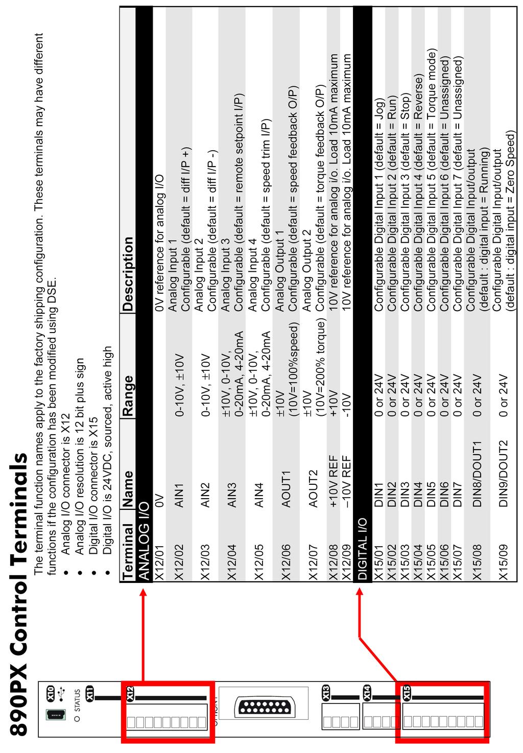
22 Appendix B: Analog and Digital I/O The terminal function names apply to the factory shipping configuration. These terminals may have different functions if the configuration has been modified using DSE. Page 22
23 Page 23
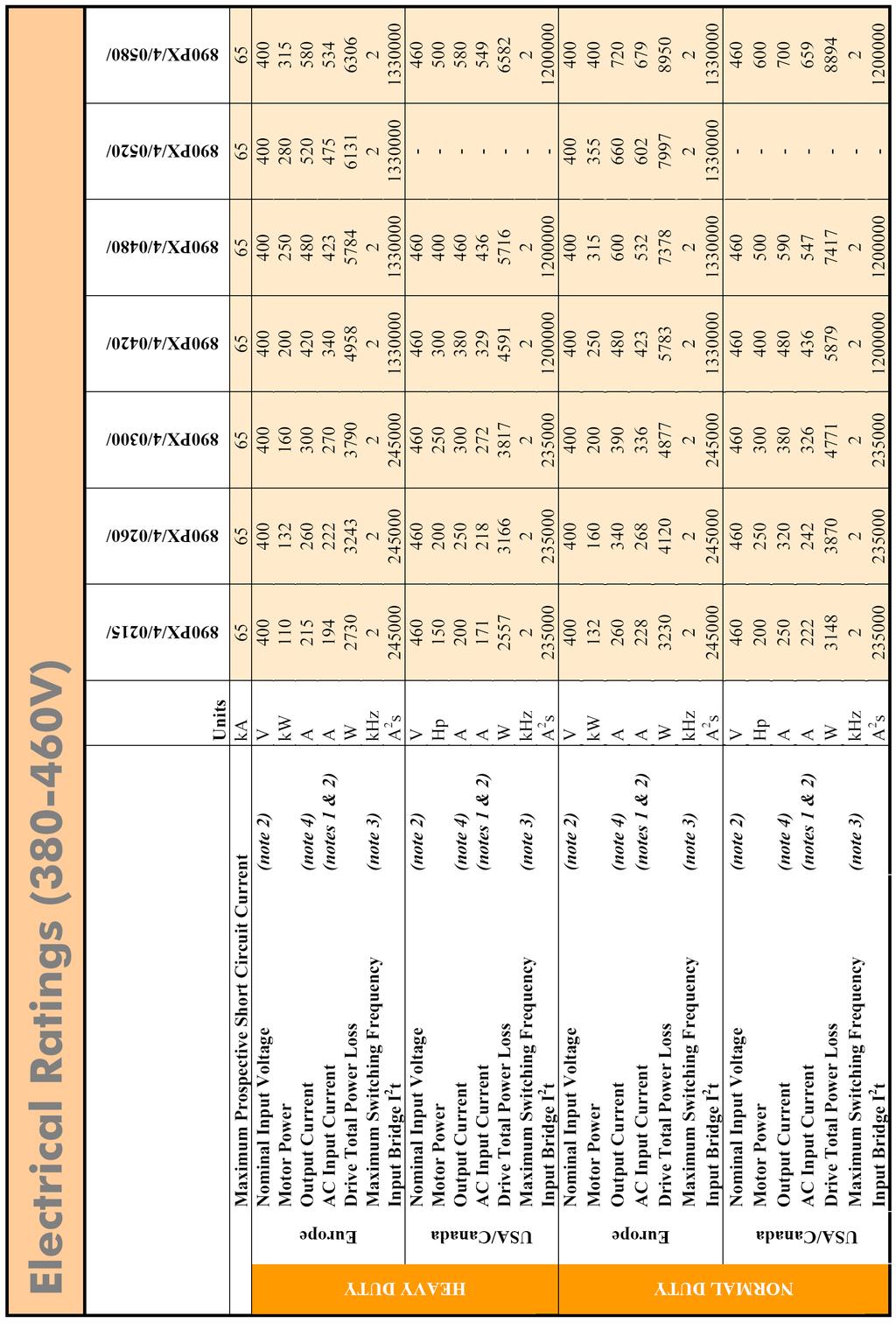
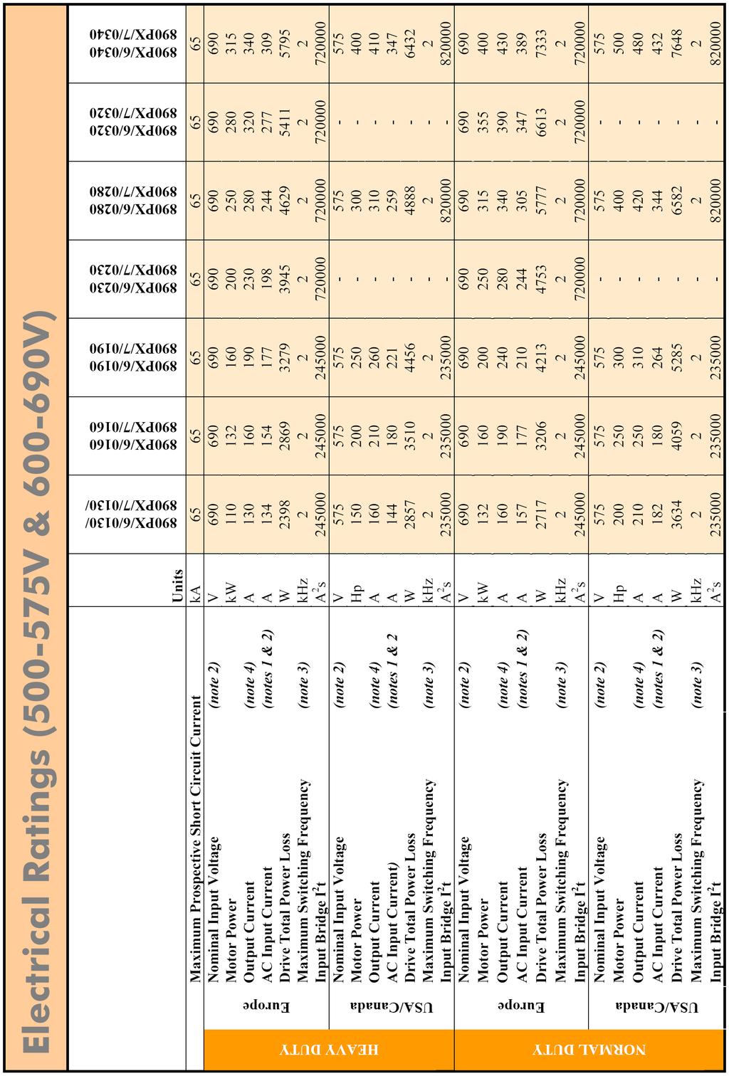
24 Appendix C: Electrical Ratings Page 24
25 Page 25
26 Page 26
890 Quickstart Manual
 890 Quickstart Manual 890CS/CD (Common Bus) Drives Frames B, C & D with STO SIL3/PLe HA501027U000 Issue 2 1) What is Safe Torque Off (STO)? It is an electronic means of preventing the 890 drive from delivering
890 Quickstart Manual 890CS/CD (Common Bus) Drives Frames B, C & D
 Drives Frames B, C & D") 890 Quickstart Manual 890CS/CD (Common Bus) Drives Frames B, C & D HA471072U000 Issue 2 (ISO A4) HA471072U001 Issue 2 (American Quarto) Contents Page Safety... 3 Introduction... 5 Installation... 7 Dimensions...
890 Quickstart Manual 890CS/CD (Common Bus) Drives Frames B, C & D HA471072U000 Issue 2 (ISO A4) HA471072U001 Issue 2 (American Quarto) Contents Page Safety... 3 Introduction... 5 Installation... 7 Dimensions...
Setpoint Isolators. Technical Manual. HA Issue Parker SSD Drives, a division of Parker Hannifin Ltd. WARRANTY
 Technical Manual HA09 Issue 008 Parker SSD Drives, a division of Parker Hannifin Ltd. All rights strictly reserved. No part of this document may be stored in a retrieval system, or transmitted in any form
HTTL Speed Feedback Communications Option
 HTTL Speed Feedback Communications Option Technical Manual HA467152U001 Issue 7 Compatible with Version 1.x Software - 690+ Compatible with Version 5.x Software - 605C Copyright 2010 Parker Hannifin Ltd
8902/E1 Sin/Cos Speed Feedback Option
 8902/E1 Sin/Cos Speed Feedback Option Technical Manual HA469252U001 Issue 2 Compatible with Version 1.x Software Copyright 2007 Parker SSD Drives, a division of Parker Hannifin Ltd. All rights strictly
AC10 series NEW FEATURES FRAME 1-5. HA502319U100 Issue 5 Product Manual ENGINEERING YOUR SUCCESS.
 NEW FEATURES FRAME 1-5 New digital input and an analogue output terminals. A side entry plug-in communication/clone socket added. AC10 series HA502319U100 Issue 5 Product Manual aerospace climate control
Unidrive M400 (Frame 1 to 4) Quick Start Guide
 Quick Start Guide") This guide is intended to provide basic information required in order to set-up a drive to run a motor. For more detailed installation information, please refer to the Unidrive M400 User Guide which is
This guide is intended to provide basic information required in order to set-up a drive to run a motor. For more detailed installation information, please refer to the Unidrive M400 User Guide which is
Unidrive M200, M201 (Frame 1 to 4) Quick Start Guide
 Quick Start Guide") This guide is intended to provide basic information required in order to set-up a drive to run a motor. Please refer to the Unidrive M200 / M20 User Guide which is available to download from www.controltechniques.com/user
This guide is intended to provide basic information required in order to set-up a drive to run a motor. Please refer to the Unidrive M200 / M20 User Guide which is available to download from www.controltechniques.com/user
8902/RE Resolver Speed Feedback Option
 8902/RE Resolver Speed Feedback Option Technical Manual HA469251U001 Issue 1 Compatible with Version 1.x Software Copyright 2005 SSD Drives Limited (formerly Eurotherm Drives Limited) All rights strictly
GV3000/SE 230 VAC 1-20 HP General Purpose (Volts/Hertz) and Vector Duty Drive Software Start-Up and Reference Manual Version 6.04
 and Vector Duty Drive Software Start-Up and Reference Manual Version 6.04") GV3000/SE 230 VAC 1-20 HP General Purpose (Volts/Hertz) and Vector Duty Drive Software Start-Up and Reference Manual Version 6.04 Instruction Manual D2-3387-4 The information in this manual is subject
GV3000/SE 230 VAC 1-20 HP General Purpose (Volts/Hertz) and Vector Duty Drive Software Start-Up and Reference Manual Version 6.04 Instruction Manual D2-3387-4 The information in this manual is subject
SMVector Additional I/O Module Installation and Operation Manual
 SMVector Additional I/O Module Installation and Operation Manual About These Instructions This documentation applies to the optional Additional I/O module for the SMVector inverter and should be used in
Installation, Operation and Maintenance Manual
 Document 481200 VGD-100 Vari-Green Drive Installation, Operation and Maintenance Manual Please read and save these instructions for future reference. Read carefully before attempting to assemble, install,
GV3000/SE General Purpose (Volts/Hertz) and Vector Duty AC Drive, HP, 230V AC
 and Vector Duty AC Drive, HP, 230V AC") Software Start-Up and Reference Manual D2-3416-2 GV3000/SE General Purpose (Volts/Hertz) and Vector Duty AC Drive, 30-100 HP, 230V AC Version 6.04 Important User Information Solid-state equipment has operational
Software Start-Up and Reference Manual D2-3416-2 GV3000/SE General Purpose (Volts/Hertz) and Vector Duty AC Drive, 30-100 HP, 230V AC Version 6.04 Important User Information Solid-state equipment has operational
8902/E1 Sin/Cos Speed Feedback Option
 8902/E1 Sin/Cos Speed Feedback Option Technical Manual HA469252U001 Issue 1 Compatible with Version 1.x Software Copyright 2005 SSD Drives Limited (formerly Eurotherm Drives Limited) All rights strictly
User Guide. IP20 & IP66 (NEMA 4X) AC Variable Speed Drive. Installation and Operating Instructions. 1 Quick Start Up kW (0.
 AC Variable Speed Drive. Installation and Operating Instructions. 1 Quick Start Up kW (0.") 1 Quick Start Up User Guide IP20 & IP66 (NEMA 4X) AC Variable Speed Drive 0.37 22kW (0.5 30HP) 110 480V Installation and Operating Instructions 1 Quick Start Up 1 1. Quick Start Up... 4 1.1. Important
1 Quick Start Up User Guide IP20 & IP66 (NEMA 4X) AC Variable Speed Drive 0.37 22kW (0.5 30HP) 110 480V Installation and Operating Instructions 1 Quick Start Up 1 1. Quick Start Up... 4 1.1. Important
ATV12H018M2 variable speed drive ATV kW hp V - 1ph
 Characteristics variable speed drive ATV12-0.18kW - 0.25hp - 200..240V - 1ph Complementary Main Range of product Altivar 12 Product or component type Product destination Product specific application Assembly
PART 1: GENERAL PART 2: PRODUCT. Effective: 12/29/10 Page 1 of 6 FECA-TE-104D
 Specification Number: 23 09 33 Product Name: FRENIC-Eco AC Drives for Variable Torque Fan & Pump Applications (1-125Hp at 208/230V and 1-900Hp at 460V) PART 1: GENERAL 1.01 SUMMARY A. This specification
Drive Technology \ Drive Automation \ System Integration \ Services. Manual. Control Cabinet Inverter MOVITRAC B Functional Safety
 Drive Technology \ Drive Automation \ System Integration \ Services Manual Control Cabinet Inverter MOVITRAC B Functional Safety Edition 05/2009 16811216 / EN SEW-EURODRIVE Driving the world Content Content
ATV310HU30N4E variable speed drive ATV310-3 kw - 4 hp V - 3 phase
 Characteristics variable speed drive ATV310-3 kw - 4 hp - 380...460 V - 3 phase Complementary Product destination Main Range of product Altivar Easy 310 Product or component type Product specific application
LiquiFlo AC General Purpose (Volts/Hertz) and Vector Duty Drive Software Start-Up and Reference Manual Version 6.4
 and Vector Duty Drive Software Start-Up and Reference Manual Version 6.4") LiquiFlo AC General Purpose (Volts/Hertz) and Vector Duty Drive Software Start-Up and Reference Manual Version 6.4 Instruction Manual D2-3410-7 The information in this manual is subject to change without
LiquiFlo AC General Purpose (Volts/Hertz) and Vector Duty Drive Software Start-Up and Reference Manual Version 6.4 Instruction Manual D2-3410-7 The information in this manual is subject to change without
AC Variable Speed Drive
 User Manual AC Variable Speed Drive IP20 & IP66 (NEMA 4X) 0.37kW 22kW / 0.5HP 30HP 110 480V 3 Phase Input Troubleshooting 0 Quick Start Up General Information and Ratings Mechanical Installation Power
ATV12P037F1 variable speed drive ATV kW hp V - 1ph - on base plate
 Characteristics variable speed drive ATV12-0.37kW - 0.55hp - 100..120V - 1ph - on base plate Complementary Main Range of product Altivar 12 Product or component type Product destination Product specific
P216. Condenser fan speed controller. Product bulletin. Features
 P216 Condenser fan speed controller Product bulletin These controllers are designed for speed variation of single phase motors, especially for fan speed control on air cooled condensers. Head pressure
P216 Series Condenser Fan Speed Controller
 P216 Series Condenser Fan Speed Controller Installation Instructions P216xxx-x Part No. 24-85895-18, Rev. D Issued 27 August 2015 Applications Refer to the QuickLIT website for the most up-to-date version
AF-600 FP TM Fan & Pump Drive. (230V to 60HP, 460/575V to 125HP Operating Instructions
 GE AF-600 FP TM Fan & Pump Drive (230V to 60HP, 460/575V to 125HP Operating Instructions Safety Safety WARNING HIGH VOLTAGE! Frequency converters contain high voltage when connected to AC mains input power.
AC Variable Speed Drive
 User Manual AC Variable Speed Drive IP66 (NEMA 4X) 0.37kW 22kW / 0.5HP 30HP 110 480V 3 Phase Input Quick Start Up General Information and Ratings Mechanical Installation Power & Control Wiring Operation
Instruc on Manual. Series S3. Industrial Inverter IP20 IP66
 Instruc on Manual Industrial Inverter Series S3 IP20 IP66 1. Quick Start Up... 4 1.1. Important Safety Information 4 1.2. Quick Start Process 5 1.3 Installation Following a Period of Staorage 5 1.4. Quick
VLT 2800 DRIVE SPECIFICATIONS
 VLT 2800 DRIVE SPECIFICATIONS Drive Input Power Input voltage 3 phase... 200 through 240, or 380 through 460; 3-phase all ratings 200 through 240, 1-phase through 2 HP Input voltage range for full output...
ATV12H075M3 variable speed drive ATV kW - 1hp V - 3ph - with heat sink
 Product datasheet Characteristics ATV12H075M3 variable speed drive ATV12-0.75kW - 1hp - 200..240V - 3ph - with heat sink Complementary Main Range of product Altivar 12 Product or component type Product
QD:CT Plus & QD:VT Installation and Operating Instructions
 Fenner QD CT Plus & V#AFD65.qxd 9/5/08 12:39 PM Page 1 QD:CT Plus & QD:VT Installation and Operating Instructions Fenner QD CT Plus & V#AFD65.qxd 9/5/08 12:39 PM Page 3 Declaration of Conformity: ERIKS
MDM 011-Z1 Regen Resistor
 MDM 011-Z1 Regen Resistor Date of creation: 10.04.2017 Version date: 10.04.2017 Article number: 09-402-011-Z1-E Publisher: SIGMATEK GmbH & Co KG A-5112 Lamprechtshausen Tel.: 06274/4321 Fax: 06274/4321-18
QUICK START GUIDE. vau4/3. Frequency converter. operating instructions /12
 operating instructions QUICK START GUIDE Frequency converter vau4/3 28100241101 12/12 1 Safety information Warning of electrical shock! Danger to life! Electrical shock can cause serious injury or even
User Guide. IP20 & IP66 (NEMA 4X) AC Variable Speed Drive kW V
 AC Variable Speed Drive kW V") User Guide IP20 & IP66 (NEMA 4X) AC Variable Speed Drive 0.37 11kW 110 480V IP20 Easy Start-Up Guide AC Supply Voltage (50 / 60Hz) L1 L2 L3 Earth L N Supply Voltage : - 115, 230, 400, 460 Volts - 1 or
User Guide IP20 & IP66 (NEMA 4X) AC Variable Speed Drive 0.37 11kW 110 480V IP20 Easy Start-Up Guide AC Supply Voltage (50 / 60Hz) L1 L2 L3 Earth L N Supply Voltage : - 115, 230, 400, 460 Volts - 1 or
ATV12HU22M3 variable speed drive ATV12-2.2kW - 3hp V - 3ph - with heat sink
 Characteristics variable speed drive ATV12-2.2kW - 3hp - 200..240V - 3ph - with heat sink Main Range of product Altivar 12 Product or component type Product destination Product specific application Assembly
PowerFlex 40 Sample Specification
 PowerFlex 40 Sample Specification GENERAL REFERENCES REGULATORY REQUIREMENTS Designed to meet the following specifications: NFPA 70 - US National Electrical Code NEMA ICS 3.1 - Safety standards for Construction
Mitsubishi D700-SC Frequency Inverter. Easy Start Guide. The Mitsubishi D700-SC Frequency Inverter range is available to order from inverterdrive.
 Mitsubishi D700-SC Frequency Inverter Easy Start Guide The Mitsubishi D700-SC Frequency Inverter range is available to order from inverterdrive.com This guide is intended to complement the user manual
ATV12P075M3 variable speed drive ATV kW - 1hp V - 3ph - on base plate
 Characteristics variable speed drive ATV12-0.75kW - 1hp - 200..240V - 3ph - on base plate Main Range of product Altivar 12 Product or component type Product destination Product specific application Assembly
Standard Options. Model 4100 Position Indicating Meter. Three Phase Motor Control. Positran Transmitter
 Standard Options Model 4100 Position Indicating Meter A percent-of-full-travel meter is supplied with a trim potentiometer resistor, terminal block and connectors. A potentiometer is required in the actuator
SECTION SOLID-STATE REDUCED VOLTAGE STARTERS
 SECTION 26 29 13.16 PART 1 - GENERAL 1.1 THE REQUIREMENT A. General: The CONTRACTOR shall provide solid-state reduced voltage motor starters, complete and operable, in accordance with the Contract Documents.
ACS Product Overview
 ACS880-07 Product Overview Description Cabinet-built single drives, ACS880-07 Our cabinet-built single drives are built to order, meeting customer needs despite any technical challenges. Designed on ABB's
GV3000/SE Operator Interface Module (OIM) User Guide Version 2.0 M/N 2RK3000
 User Guide Version 2.0 M/N 2RK3000") GV3000/SE Operator Interface Module (OIM) User Guide Version 2.0 M/N 2RK3000 Instruction Manual D2-3342-2 The information in this manual is subject to change without notice. Throughout this manual, the
GV3000/SE Operator Interface Module (OIM) User Guide Version 2.0 M/N 2RK3000 Instruction Manual D2-3342-2 The information in this manual is subject to change without notice. Throughout this manual, the
VARIABLE SPEED DRIVES VLA1 SERIES
 VARIABLE SPEED DRIVES VLA1 SERIES VLA1 series SIMPLE COMPACT VERSATILE TOP PERFORMANCE IE1 CLASS energy efficiency IE0 IE2 EN 50598-2 IE2 efficiency class (EN50598-2) The drive efficiency is 25% higher
ABB Industrial Systems Inc. Standard Drives. ACH500-06E Effective 6/1/95
 Part 1 - GENERAL ASEA BROWN BOVERI ABB Industrial Systems Inc. Standard Drives ACH500-06E Effective 6/1/95 Sample Specification for Adjustable Frequency Drives (2 to 400 HP) for Variable Torque Applications
FLÄKTGROUP OFFERS A WIDE RANGE OF PER- MANENT MAGNET MOTORS (PM) AND FREQUENCY CONVERTERS FOR PLUG FANS. POWER RANGE IS FROM 0,8 KW TO 15 KW.
 AND FREQUENCY CONVERTERS FOR PLUG FANS. POWER RANGE IS FROM 0,8 KW TO 15 KW.") CENTRIFLOW PUR 3D (A, PLUG B, C, D) FAN GMPM FC101 AND SLIDE IN FREQUENCY ROTOR CASSETTE CONVERTER QUICK GUIDE FLÄKTGROUP OFFERS A WIDE RANGE OF PER- MANENT MAGNET MOTORS (PM) AND FREQUENCY CONVERTERS
CENTRIFLOW PUR 3D (A, PLUG B, C, D) FAN GMPM FC101 AND SLIDE IN FREQUENCY ROTOR CASSETTE CONVERTER QUICK GUIDE FLÄKTGROUP OFFERS A WIDE RANGE OF PER- MANENT MAGNET MOTORS (PM) AND FREQUENCY CONVERTERS
Firmware Manual - EC Series Drives
 1 Firmware Manual - EC Series Drives Doc Ver 1.01 Firmware ver: EC series drives For installation details refer to Hardware Manual Safety: Read safety instruction in hardware manual before installation
PanelView Plus/VersaView CE Terminals and Display Modules
 Installation Instructions PanelView Plus/VersaView CE Terminals and Display Modules (Catalog Numbers 2711P-xxxxxx, 6182H-xxxxxx) English Inside: Overview...2 For More Information...2 Modular Components...3
E510. Compact Drive IP 20/ NEMA HP (230V) 1-75 HP (460V)
 1-75 HP (460V)") E510 Compact Drive IP 20/ NEMA 1 0.5-40 HP (230V) 1-75 HP (460V) Control Mode Application & Selection Guide The E510 compact AC Drive is an easily configurable product that controls many motor driven applications.
E510 Compact Drive IP 20/ NEMA 1 0.5-40 HP (230V) 1-75 HP (460V) Control Mode Application & Selection Guide The E510 compact AC Drive is an easily configurable product that controls many motor driven applications.
Operating instructions. Switching amplifier DN0210 DN / / 2015
 Operating instructions Switching amplifier DN0210 DN0220 UK 80011079 / 00 01 / 2015 Contents 1 Preliminary note...4 1.1 Symbols used...4 1.2 Warning signs used...4 2 Safety instructions...5 2.1 General...5
IP20 Easy Start Up Guide
 IP20 Easy Start Up Guide AC Supply Voltage (50 / 60Hz) L1 L2 L3 Earth L N Supply Voltage : 230, 400, 460 Volts 1 or 3 Phase Check the drive rating information on page 27 Fuses or MCB Fuses or MCB, Cable
High Performance Output Filter Instruction Manual
 High Performance Output Filter Instruction Manual R TECHNOLOGY AND QUALITY ASSURANCE Since 1976 Zener Electric has supplied many thousands of drives to industry. These drives have been installed into numerous
AC Variable Speed Drive 0.75kW 250kW / 1HP 350HP Volt 1 & 3 Phase. Installation & Operating Instructions
 AC Variable Speed Drive 0.75kW 250kW / 1HP 350HP 200 480 Volt 1 & 3 Phase Installation & Operating Instructions IP20 Easy Start Up Guide AC Supply Connection Supply Voltage 3 Phase Units : Connect L1 L2
Easy To Use OEMS Take Note
 MA7200 Features Sensorless Vector Precise speed and torque control for the most demanding system performance. Simple set-up through autotuning function. The MA7200 can be operated in sensorless vector
Operating instructions. Speed monitor D / / 2014
 Operating instructions Speed monitor D200 80005257 / 00 05 / 2014 Contents 1 Preliminary note...4 1.1 Symbols used...4 1.2 Warning signs used...4 2 Safety instructions...5 2.1 General...5 2.2 Target group...5
SMVector Additional I/O Module Installation and Operation Manual
 SMVector Additional I/O Module Installation and Operation Manual About These Instructions This documentation applies to the optional Additional I/O module for the SMVector inverter and should be used in
Line reactors SINAMICS. SINAMICS G130 Line reactors. Safety information 1. General. Mechanical installation 3. Electrical installation
 Safety information 1 General 2 SINAMICS SINAMICS G130 Mechanical installation 3 Electrical installation 4 Technical specifications 5 Operating Instructions Control version V4.7 04/2014 A5E00331462A Legal
SECTION VARIABLE FREQUENCY DRIVES
 PART 1 GENERAL 1.01 DESCRIPTION This specification section establishes the requirements for variable frequency motor drives. The associated motor(s) shall be specified separate from the drive and listed
Distributed Power System SA3100 Drive Configuration and Programming
 Distributed Power System SA3100 Drive Configuration and Programming Instruction Manual S-3056-1 Throughout this manual, the following notes are used to alert you to safety considerations:! ATTENTION: Identifies
SM-I/O Plus. Solutions module for UNIDRIVE SP. User guide. This manual is to be given to the end user. Réf en / a
 M Réf. 3952 en - 09.2005 / a T2 digital I/O 1 state T2 output select??.?? X.09 X.31 0 1 x(-1)??.?? This manual is to be given to the end user 2 T2 digital I/O 1 Positive logic select 1 0 X.29 X.11 x(-1)
PSU. User s manual. Rev. 0
 PSU User s manual Rev. 0 2010 1 This user manual is for the standard version of the converter. All information in this user manual, including methods, techniques and concepts described herein, are proprietary
Frequency Inverters WJ200 Series Compact Inverter
 Frequency Inverters Compact Inverter Frequency Inverters Compact Inverter Industry leading performance High starting torque of 200% or greater achieved using sensorless vector control (when sized for heavy
ATV310H075N4E variable speed drive ATV kw - 1 hp V - 3 phase
 Characteristics variable speed drive ATV310-0.75 kw - 1 hp - 380...460 V - 3 phase Main Range of product Altivar Easy 310 Product or component type Product specific application Assembly style Device short
690+ Series AC Drive Frame B, C, D, E & F
 690+ Series AC Drive Frame B, C, D, E & F Product Manual HA465492U005 Issue 5 Compatible with Version 5.x Software Copyright 2007 Parker SSD Drives, a division of Parker Hannifin Ltd. All rights strictly
ACOPOSinverter P74. User's Manual. Version: 2.20 (August 2016) Model no.: Original instruction
 Model no.: Original instruction") ACOPOSinverter P74 User's Manual Version: 2.20 (August 2016) Model no.: MAACPIP74-ENG Original instruction All information contained in this manual is current as of its creation/publication. We reserve
ACOPOSinverter P74 User's Manual Version: 2.20 (August 2016) Model no.: MAACPIP74-ENG Original instruction All information contained in this manual is current as of its creation/publication. We reserve
Resolver to Digital Expansion Board
 Resolver to Digital Expansion Board Catalog No. EXB009A01 Installation and Operating Manual 6/98 MN1313 Table of Contents Section 1 General Information............................. 1-1 Introduction....................................
QUICK REFERENCE GUIDE
 acknowledges changed values, fault history, and is pressed to enter program resets starts the motor when the panel is the stops the motor when the panel is the - and I/O CONNECTIONS SCREEN DISPLAYS QUICK
AC10 series. Quick-Start Guide IP HP ( kw) IP HP ( kw) AC10 Expanded Quick-Start Guide HA474130U002 Issue 1
 IP HP ( kw) AC10 Expanded Quick-Start Guide HA474130U002 Issue 1") AC10 series Quick-Start Guide IP20 0.25-250 HP (0.2-180 kw) IP66 0.5-125 HP (0.4-90 kw) AC10 Expanded Quick-Start Guide HA474130U002 Issue 1 OFFER OF SALE The items described in this document are hereby
AC10 series Quick-Start Guide IP20 0.25-250 HP (0.2-180 kw) IP66 0.5-125 HP (0.4-90 kw) AC10 Expanded Quick-Start Guide HA474130U002 Issue 1 OFFER OF SALE The items described in this document are hereby
ATV1200A kv kva. Phase-shifting transformer Medium voltage arrestors Cooling fans Human machine interface Plinth (2) Power cells (9)
 Power cells (9)") Characteristics medium voltage variable speed drive ATV1200-3.3 kv - 370 kva Main Range of product Altivar 1200 Product or component type Device short name Product destination Product specific application
Characteristics medium voltage variable speed drive ATV1200-3.3 kv - 370 kva Main Range of product Altivar 1200 Product or component type Device short name Product destination Product specific application
ATV1200A kv kva
 Characteristics medium voltage variable speed drive ATV1200-10 kv - 5000 kva Main Range of product Altivar 1200 Product or component type Device short name Product destination Product specific application
ATV1200A kv kva
 Characteristics medium voltage variable speed drive ATV1200-3.3 kv - 3500 kva Main Range of product Altivar 1200 Product or component type Device short name Product destination Product specific application
VARIABLE SPEED DRIVES
 VARIABLE SPEED DRIVES VARIABLE SPEED DRIVES 0.4...75kW THREE-PHASE COMPACT, VERSATILE HIGH PERFORMANCE Automatic car washing equipment APPLICA TION AREAS Packaging Automatic and semi-automatic packaging
NHP MODdrive Single Phase
 User Guide NHP MODdrive Single Phase AC Variable Speed Drives For PSC and Shaded Pole Single Phase Motors 0.37 1.1kW 240V AC Single Phase Input / Single Phase Output Installation and Operating Instructions
USER MANUAL INSTALLATION MANUAL. Isolation transformers. ITR Isolation Transformer 7000 W 230V/32A
 USER MANUAL INSTALLATION MANUAL Isolation transformers ITR000702000 Isolation Transformer 7000 W 230V/32A Victron Energy B.V. The Netherlands General phone: +31 (0)36 535 97 00 Customer support desk: +31
Powered to Perform. Everyday Reliability. Exceptional Value. Expertise and Support
 A decentralized solution. Many drive applications utilize control panels with complex wiring taking up large amounts of space. These control panels are often mounted away from the application requiring
CDD4 Duct Carbon Dioxide Transmitter
 Drill or punch a 1-1/8 or 1-1/4 hole in the duct at the preferred location and insert the probe into the hole to mark the enclosure mounting holes. Remove the unit and drill the four mounting holes. Clean
VARIABLE SPEED DRIVES
 VARIABLE SPEED DRIVES VARIABLE SPEED DRIVES 0.4...30kW THREE-PHASE COMPACT, VERSATILE HIGH PERFORMANCE Automatic car washing equipment APPLICA TION AREAS Packaging Automatic and semi-automatic packaging
60131/2 Te ESC ENT RUN ESC ENT RUN ESC ENT RUN ESC ENT RUN ESC ENT RUN. stop reset FWO REV. stop reset FWO REV. stop reset FWO REV. stop reset FWO REV
 5 4 60/ Te Characteristics : pages 60/7 to 60/9 pages 60/0 and 60/ pages 604/ to 605/8 pages 60/ to 60/5 Presentation Applications A frequency inverter for -phase asynchronous squirrel cage motors, the
1. Introduction About the Vacon 5X drive Identifying the drive by model number Drive model numbers...7
 1 vacon Table of Contents Contents Document: DPD00086 Version release date: 19.12.08 1. Introduction...3 1.1 Product overview...3 1.2 Important safety information...3 1.3 Electromagnetic compatibility
VS1MX AC Extreme Duty Microdrive
 VS1MX AC Extreme Duty Microdrive 6/09 Installation & Operating Manual Any trademarks used in this manual are the property of their respective owners. Important: Be sure to check www.baldor.com for the
PHASETRONICS. SCR Power Control Specialists. EP1 Series Power Control Single Phase SCR Amps OPERATION & SERVICE MANUAL
 PHASETRONICS Specialists EP1 Series Power Control Single Phase SCR 10-50 Amps OPERATION & SERVICE MANUAL Phasetronics, Inc. P.O. Box 5988 1600 Sunshine Drive Clearwater, FL 33765 (727)573-1900 FAX(727)573-1803
SED2 Variable Frequency Drives
 SED2 Variable Frequency Drives Startup Procedure and Checklist Document No. 155-718 Table of Contents Prerequisites...1 Preparing for SED2 VFD Startup...1 HVAC Startup Procedure for SED2 with Bypass Option...4
Drive Technology \ Drive Automation \ System Integration \ Services. Manual. MOVITRAC MC07B Functional Safety
 Drive Technology \ Drive Automation \ System Integration \ Services Manual MOVITRAC Functional Safety Edition 12/2011 19396414 / EN SEW-EURODRIVE Driving the world Contents Contents 1 General Information...
Zenith DS9000 Dispensing System
 Page Date: 04/2009 Zenith DS9000 Dispensing System Installation & Operation Manual Page 2 Table of Content Introduction... 3 Control Specification... 4 Wiring Diagram... 5 Wiring Instructions... 6 Field
Specification Number: Product Name: FRENIC-Mega AC Drives for General Purpose Applications (½ - 150Hp at 230V and ½ Hp at 460V)
") Specification Number: 26 29 23 Product Name: FRENIC-Mega AC Drives for General Purpose Applications (½ - 150Hp at 230V and ½ - 1000Hp at 460V) PART 1: GENERAL 1.01 SUMMARY A. This specification provides
Specification Number: 26 29 23 Product Name: FRENIC-Mega AC Drives for General Purpose Applications (½ - 150Hp at 230V and ½ - 1000Hp at 460V) PART 1: GENERAL 1.01 SUMMARY A. This specification provides
Table of Contents. Safety. Attention. Warnings
 Solstart Miniature Soft Starter 8-58A, 220-600V Instruction Manual Ver. 21.2. 2002 Table of Contents Page Subject 3 Starter Selection 4 Installation Notes 5 Wiring 6 Starter Settings & Start-up Procedure
VARIABLE SPEED DRIVES
 VARIABLE SPEED DRIVES VARIABLE SPEED DRIVES 0.4...110kW THREE-PHASE COMPACT, VERSATILE HIGH PERFORMANCE Automatic car washing equipment APPLICA TION AREAS Packaging Automatic and semi-automatic packaging
lnvertek Drives.com ct,ve ELECTRICAL SUPPLIERS LTD
 lnvertek Drives.com ft ct,ve ELECTRICAL SUPPLIERS LTD OptidriveE2 Technical Product Guide 1.1 OVERVIEW Range IP20 IP66X (NON SWITCHED) IP66Y (SWITCHED) Supply Voltage Range Power Range 110 115 + / 10%
User Guide. Cloning interface small option module for Unidrive and Commander GP. Part Number: Issue Number: 3
 User Guide UD55 Cloning interface small option module for Unidrive and Commander GP Part Number: 0460-0095 Issue Number: 3 General Information The manufacturer accepts no liability for any consequences
Installation and Commissioning Instructions AC drive VersiDrive i... /E
 electronic Installation and Commissioning Instructions AC drive VersiDrive i... /E Quality is our Drive. Declaration of Conformity PETER electronic GmbH & Co. KG hereby states that the VersiDrive i /E
Master Pulse Reference/ Isolated Pulse Follower Expansion Board
 Master Pulse Reference/ Isolated Pulse Follower Expansion Board Catalog No. EXB005A01 Installation and Operating Manual 2/03 MN1312 Y1 Table of Contents Section 1 General Information.............................
AC Variable Speed Drive 0.75kW 250kW / 1HP 350HP Volt 1 & 3 Phase. Installation & Operating Instructions
 AC Variable Speed Drive 0.75kW 250kW / 1HP 350HP 200 480 Volt 1 & 3 Phase Installation & Operating Instructions Optidrive P2 IP20 Easy Start Up Guide AC Supply Connection Supply Voltage 3 Phase Units :
ETM MD100 Drive System 1/2HP (370W) User Manual. Table of Contents. Drive Features
 User Manual. Table of Contents. Drive Features") Table of Contents Drive Features... 1 Drive Specifications... 2 Certifications... 3 Installation - Drive Dimensions... 3 Motor Dimensions (mm)... 4 Drive Mounting... 4 Wiring... 5 I/O Terminals... 9 Menu...
Table of Contents Drive Features... 1 Drive Specifications... 2 Certifications... 3 Installation - Drive Dimensions... 3 Motor Dimensions (mm)... 4 Drive Mounting... 4 Wiring... 5 I/O Terminals... 9 Menu...
A drive dedicated to variable speed control for HVAC applications
 A drive dedicated to variable speed control for HVAC applications Designed for easy installation in mechanical fan and pump systems with reliable connectivity to building automation networks. VTAC 9 Drive
GV3000/SE AC Drive Hardware Reference, Installation, and Troubleshooting VAC Version 6.04
 GV3000/SE AC Drive Hardware Reference, Installation, and Troubleshooting -20 HP @ 230 VAC Version 6.04 c Instruction Manual D2-3388-4 The information in this manual is subject to change without notice.
SORDS ELECTRIC ~ MA7200. Sensorless Vector AC Inverter.
 www.sordselectric.com MA7200 Sensorless Vector AC Inverter Features and Benefits Sensorless Vector The MA7200 has precise speed and torque control for the most demanding system performance and simple set-up
DM-918 OPERATIONS MANUAL AUTORANGING MULTIMETER
 DM-918 OPERATIONS MANUAL AUTORANGING MULTIMETER SAFETY INFORMATION The following safety information must be observed to ensure maximum personal safety during the operation of this meter: This meter is
VS1ST AC Microdrive. 8/08 Installation & Operating Manual MN767
 VS1ST AC Microdrive 8/08 Installation & Operating Manual MN767 Any trademarks used in this manual are the property of their respective owners. Important: Be sure to check www.baldor.com for the latest
690+ Series AC Drive. Frame B, C, D, E & F. Installation Product Manual. HA465492U005 Issue 3. Compatible with Version 5.
 690+ Series AC Drive Frame B, C, D, E & F Installation Product Manual HA465492U005 Issue 3 Compatible with Version 5.x Software Copyright 2004 SSD Drives Limited (formerly Eurotherm Drives Limited) All
LS M100 Frequency Inverter Easy Start Guide
 The range is available to order from inverterdrive.com This guide is intended to complement the user manual provided by the manufacturer. It is provided as a basic introduction to the product for Inverter
Torque Series LCD Remote Panel Installation/Operation Manual Model: TQ-DSP-12/24
 Torque Series LCD Remote Panel Installation/Operation Manual Model: TQ-DSP-12/24 Section Page Introduction 1 Materials Provided 1 I) Safety Instructions 1 A) Inverter Safety Instructions 1 B) Battery Safety
This manual was downloaded on (0) TS8000. Firewire Option 8000/FA/00 HA Issue 1
 TS8000. Firewire Option 8000/FA/00 HA Issue 1") TS8000 Firewire Option 8000/FA/00 HA471483 Issue 1 Copyright SSD Drives, Inc. 2006 All rights strictly reserved. No part of this document may be stored in a retrieval system, or transmitted in any form
TS8000 Firewire Option 8000/FA/00 HA471483 Issue 1 Copyright SSD Drives, Inc. 2006 All rights strictly reserved. No part of this document may be stored in a retrieval system, or transmitted in any form