Uber Tuber FX TYPE: Tube Overdrive 2018 madbeanpedals. Important stuff:
|
|
|
- Maximillian Glenn
- 5 years ago
- Views:
Transcription
1 Uber Tuber FX TYPE: Tube Overdrive 2018 madbeanpedals Important stuff: The UberTuber is a tube-based overdrive. It requires an 18v 500mA (min.) power supply. I suggest the Dunlop 18v supply if you do not have a PS that meets this requirement. You cannot use a charge pump to power the UberTuber. The current requirements are far too high. Even though the UberTuber is designed as a relatively low voltage circuit, it requires high current consumption and produces high temperatures. There is a risk of injury if you do not handle it properly. Always make sure that your power is hooked up correctly. The tube and 39R 5W resistor will get hot and you will get burned if you touch either. Be aware of potential capacitor discharge whether or not the circuit is powered. Use at your own risk: madbeanpedals is not responsible for any injury sustained due to improper handling when building or operating this effect project. 1

2 Main Board 2.3" W x 2.625" H Daughter Board 0.6" W x 0.8" H Terms of Use: You are free to use purchased UberTuber circuit boards for both DIY and small commercial operations. You may not offer UberTuber PCBs for resale or as part of a kit in a commercial fashion. Peer to peer re-sale is, of course, okay. 2
.")
3 Trace Routing Unconnected pads are joined via ground planes (not shown). 3
4 B.O.M. Resistors Caps Diodes R1 1k C1 100pF D1 1N4004 R2 1M C2 47n D2, D3 LED R3 1M C3 1uF D5, D6 1n914 R4 22k C4 4n7 Transistors R5 100k C5 100pF Q1 J201 R6 1k5 C6 1uF Tube R7 47k C7 10n SMT_ R8 100k C8 10n Switches R9 1k5 C9 22n BOOST SPDT R10 1k5 C10 1uF Header R11 1k5 C11 220n 8-pin Right Angle R12 47k C12 1uF Trimpot R13 1k C13 470uF T1 100k R14 1k C14 470uF Pots R15 4k7 C15 1uF SAT 10kB R16 4k7 C16 100n CUT 50kA R17 10R C17 220uF LEVEL 100kA R18 39R DRIVE 500kB 4
5 Shopping List Value QTY Type Rating 10R 1 Metal Film 1/2W 39R 1 Wirewound 5W 1k 3 Metal Film 1/4W 1k5 4 Metal Film 1/4W 4k7 2 Metal Film 1/4W 22k 1 Metal Film 1/4W 47k 2 Metal Film 1/4W 100k 2 Metal Film 1/4W 1M 2 Metal Film 1/4W 100pF 1 Ceramic / MLCC 25v min. 100pF 1 Silver Mica 25v min. 4n7 1 Film 25v min. 10n 2 Film 25v min. 22n 1 Film 25v min. 47n 1 Film 25v min. 100n 1 Film 25v min. 220n 1 Film 25v min. 1uF 5 Electrolytic 25v 220uF 1 Electrolytic 16v 470uF 2 Electrolytic 25v 1N Electrolytic 25v LED 2 Diffused 3mm 1n914 2 J201 1 SMT * Header 1 8-pin, Right Angle 2.54mm SPDT 1 On/On 100k 1 Bourns 3362p 10kB 1 Long Pin PCB Mout 16mm 50kA 1 Long Pin PCB Mout 16mm 100kA 1 Long Pin PCB Mout 16mm 500kB 1 Long Pin PCB Mout 16mm The 10R 1/2W resistor, 39R 5W resistor and the 8-pin header are included with purchase. 5
6 6111 Tube (You can use either the 6111 or 6111WA): If you are a registered member of CE Distribution (limited to business accounts) Tube alternative (untested in this build but it should work): 100pF Silver Mica: CDE/CD15FD101JO3F?qs=sGAEpiMZZMtLiKaZgV7flTkVLq%2fu65ALImXuWCi9kNM%3d 1uF Electrolytic 50v: PslgiMw%3d%3d 220uF 25v: dadbxfchabldnsa%3d%3d 470uF 35v: bddobm%3d 1N4004: T?qs=sGAEpiMZZMtbRapU8LlZD6Aoap19JQAxV7DXsJ2UlJI%3d J201: Bourns 3362p 100k trimpot: SPDT: SubMini SPDT: 16mm Right Angle Long Pin Pots: Lumberg ¼ Jacks (recommended, but not required): DC Jack (required for size): 6
7 125B Drill Guide 7.65" H x 5.52" W Photoshop file: The red outline shows the approximate dimensions of the sub-mini tube. The drill spots over it are for drilling vent holes to allow heat to escape from the 125B enclosure. This may not be totally necessary but I recommend doing it. It s a little more work but could prevent overheating and it looks cool. Just use a drill bit that s small enough to leave space between holes. 7

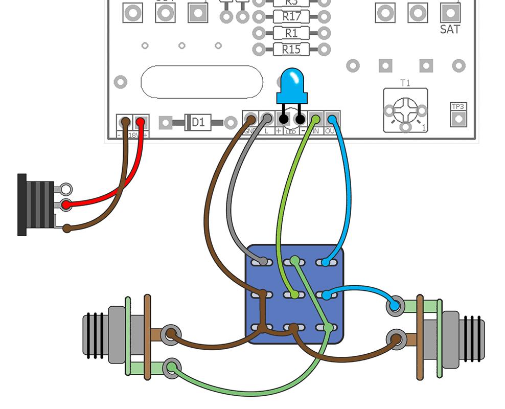
8 Wiring Guide 8
9 The UberTuber is the 10 th subminiature tube circuit project I designed. Wait What the ham and crackers, you say? You ve never released a tube project! True none of the previous nine projects were terribly good. I could never quite get it right; whether it was in how to handle the power supply, the actual layout and mounting of the tube, or just the circuit idea itself. The UberTuber is the first one I felt was good enough for public consumption. And it is really, really good (I m a humble man). Why a tube overdrive? Because we can, silly! But, there is more to it. A tube overdrive bridges the gap between a discrete overdrive and a high gain tube amp. We use discrete components in our overdrive pedals to mimic or add to that sweet compression we get from pre-amp tubes running at a few hundred volts in our amplifiers. And, discrete designs do a great job at that usually. But, a sub-mini tube overdrive gives us an alternative some of that compression and even harmonics good amps produce at relatively low voltages. Some sub-mini tubes are capable of running at v, however I chose to stick to a relatively safe 18v. The main reason for this is safety for the builder. With proper handling, this project is relatively safe to make and while there is a risk of injury you probably won t electrocute yourself. But, as I mentioned on pg.1 you must be careful when handling. I ve burned myself on the tube and 5W resistor more than once because I got careless. You will too, if you are not careful. So, do the thing and not the other thing. Controls Level Sets the total volume output. Drive Sets the amount of overdrive. Sat CCW: minimum saturation for more of a boost. CW: maximum saturation for thicker overdrive. Cut CW: rolls off treble. Boost This switch increases volume output while adding some pick attack. Basically the UberTuber but rude. A RuderUberTuber, if you will. T1 Sets the bias point of the output JFET. Notes Please see the build guide at the end of this document. The sub-mini tube has two sources of power: heater and plate voltages. In our case the sub-mini heater runs optimally at 6.3v. Current consumption is approximately 300mA from the datasheet. The heater voltage is produced by using a large resistor to drop the supply voltage to the appropriate value under load. This works out to be 39 Ohms at 5W. To calculate that we use these two formulas: V =I*R Rearranging for R we calculate the needed resistance by getting the voltage difference and dividing by the current draw. Here R is Ohms, V is Volts and I is Amperes. R = (18 6.3)/0.3 = 39 Ohm To calculate the necessary wattage for the resistor we use P = I^2*R Where P is Watts, I is amperes and R is Ohms. This gives us P = 0.3*0.3*39 = 3.51W 3.51W is the minimum wattage we want to use to ensure our dropping resistor doesn t burn up. So, in this case we ll use 5W. BTW: you might wonder why insist on an 18v supply for the entire circuit? Why not use a 9v supply, use the appropriate value dropping resistor for the tube heaters and then use a charge pump to get the 18v for the lower current needed for the tube plates? The answer is you could do that in some cases. For this first tube design I decided to play it safe: a dedicated supply with tons of decoupling and filtering to make this overdrive very quiet and avoid any potential noise or heterodyne the circuit might produce with other effects. 9
10 Mods The one area I compromised on in the circuit was in dialing in the bass frequencies. As designed, C4 and the Drive pot form a high pass filter that rolls off some of low end. The reason I choose C4 as 4n7 is that higher values tended to get very flubby with high Drive settings on neck pickups. So much so that it seemed necessary to dial some of it out to keep the circuit balanced. If you want more bass and don t care about a flabby fat neck pickup then use 15n or 22n for C4. Voltages There are four test points for voltages, TP1 TP4. Use your multimeter to verify these voltages on your build: TP1 and TP2 are the two plate voltages. These should be between 11 and 11.5v. TP3 is the drain voltage for Q1. Using the 100k trimmer set the voltage on TP3 to about 11.5v. TP4 is the heater. It should read about 6.3v. A little above or below is fine. The VC voltage should be between 17.5v and 18v. It can be measured by taking a reading on the positive lead of either C13 or C14 on the top of the main board. My Voltages TP1 Plate 11.52v TP2 Plate 11.36v TP3 Q1 Drain 11.5v TP4 Heater 6.36v VC 17.97v Current Draw: 18v 10
11 11
.")
12 Build Guide The UberTuber comprises two PCBs: the main board and daughter board. The main board houses all the circuit components. The daughter board holds the sub-mini tube. The daughter board is mounted at a right angle to the main board. When completed, the tube and control pots are on the same side (facing the top of the enclosure). Begin by populating all the top layer components and soldering them in place. The electrolytic caps are bent as shown to be parallel to the board. This keeps their height low and helps fit everything in the 125B. If you use low-profile electrolytic caps (under 5mm high) you don t need to bend them at 90 : just solder them flush mounted. BTW: this version used a 470pF for C5 which I later changed to 100pF Silver Mica. 12

13 Solder the 39R 5W resistor on the bottom of the PCB as shown. While there is a cut-out on the PCB to allow heat to pass through the board, it s important to leave a small air gap between the resistor and PCB. This will prevent the PCB from taking excess heat and potentially damaging it. 13

14 Solder the two 470uF caps to the bottom of the PCB. Then solder the two 3MM LEDs. Note: these LEDs are optional and not necessary to make the circuit work. They serve to light up the tube if you are drilling air vents into your enclosure (something you should do). You can omit the LEDs if you want. 14

15 Soldering the pots is more of a challenge than usual because there is no support to hold them in place. What I recommend doing it soldering the middle pin then while the solder is hot gently move it into place so the pins and PCB are at a right angle. Don t force this too hard or you will damage the PCB pads! 15

16 Solder the middle pins of the remaining pots like you did the first one. After that, flip the board over and top solder the remaining pins on all the pots. You should probably trim the tabs off the pots before soldering them in unlike me. 16

17 Next solder the switch in for the Boost control. You can use a regular size SPDT or a mini switch like I did here. Either should fit. 17


18 The leads on the tube form a U shape. This tells you the orientation. You can see the same configuration on the daughter board. The pin layout is: K: Cathode H: Heater G: Grid P: Plate The pin layout is symmetrical along the vertical axis. The labeled side of the daughter board is the solder side. However, if you accidently solder to the other side don t worry it will still work because of the symmetry. 18


19 Inserting the tube into the daughter board can be a bit aggravating. I found this procedure makes it a lot easier: cut pairs of leads to different lengths across the vertical access. This means you only have to insert two leads at a time rather than all 8. Cut these pairs of pins to different lengths 19

20 Note: this is a different daughter board I used on the prototype. It is slight taller than the final production board. Push the tube so that it flush mounted to the PCB and solder the pins in place. Next, install the right angle pins. Solder the long side of the pins to the daughter board and trim the excess. The short side of the pins are the ones that get soldered to the main board. 20


21 Solder the completed daughter board to the main board. This is also tricky like the pots because there is no support. The way I did it was to use some BluTac on the right angle pin header to hold the daughter board at an approximate right angle. Then I soldered one of the middle pins of the header on top. After that, I very gently pushed the daughter board into place so it formed a 90 angle with the main board. Use whatever method you want to get the end result just be gentle when moving or pushing the daughter board around so you don t damage any solder joints or pads. I also installed a small support for the tip of the tube. This is probably not necessary but it certainly doesn t hurt. I used some 20 gauge buss wire, bent one end into a small circle and soldered. The other end is soldered into this extra pad on the main PCB. 21

22 The completed assembly with the I/O wires soldered in. You can PCB mount your bypass indicator LED if you want. I soldered the blue LED with wires because that s the color I wanted for this build and I did not have any with full leads. 22

23 The completed circuit with power. You can see the LEDs I used are pretty bright! Again, those are optional. If you don t like them, don t use them. Once they are installed you cannot turn them off when the circuit is powered. Again: when the circuit is powered keep your fingers away from the tube and 39R resistor. You will get burned if you touch them. It generally takes them a few minutes to cool off when the power is removed. BTW: The 5kC pot was later changed to 10kB so don t be confused by that. 23
3PRR. FX TYPE: Utility 2015 madbeanpedals W x 1.11 H change-log: Removed 10R current limiting resistor.
 3PRR FX TYPE: Utility 2015 madbeanpedals 1.815 W x 1.11 H 2015 change-log: Removed 10R current limiting resistor. This PCB is designed for the typical BLUE 3PDT footswitch. Other footswitches may or may
Super Skwisher. Ross Compressor +++
 Super Skwisher Ross Compressor +++ Contents of this document are 2015 Pedal Parts Ltd. No reproduction permitted without the express written permission of Pedal Parts Ltd. All rights reserved. Important
2015 edition FT TYPE: Utility madbeanpedals. Previous version of the Road Rage:
 Road Rage 2015 edition FT TYPE: Utility madbeanpedals Previous version of the Road Rage: http://www.madbeanpedals.com/projects/roadrage/docs/roadrage.zip 1.25 W x 0.825 H 2015 change-log: Removed 10R current
FX TYPE: FUZZ PCB artwork m2010 madbeanpedals Release date: REVISED:
 http://www.madbeanpedals.com presents zygote FX TYPE: FUZZ PCB artwork m2010 madbeanpedals Release date: 12.10.10 REVISED: 03.24.11 The Zygote is an all in one fuzz. It allows you to build several types
Deep Vibes. Wobbly Optical Vibe action
 Deep Vibes Wobbly Optical Vibe action Contents of this document are 2018 Pedal Parts Ltd. No reproduction permitted without the express written permission of Pedal Parts Ltd. All rights reserved. Important
PROJECT SUMMARY A reproduction of a rare and very expensive low-to-mid-gain overdrive with 3-band EQ that is popular in the Nashville scene.
 PROJECT NAME QUANTUM BASED ON Ibanez MT-0 Mostortion BUILD DIFFICULTY Easy EFFECT TYPE DOCUMENT VERSION Overdrive / Distortion.0.0 (08--5) PROJECT SUMMARY A reproduction of a rare and very expensive low-to-mid-gain
TEMPEST PROJECT NAME. BASED ON Friedman BE-OD / Dirty Shirley. BUILD DIFFICULTY Intermediate. DOCUMENT VERSION Amp-Like Distortion 1.0.
 PROJECT NAME TEMPEST BASED ON Friedman BE-OD / Dirty Shirley BUILD DIFFICULTY Intermediate EFFECT TYPE DOCUMENT VERSION Amp-Like Distortion.0. (09-0-08) PROJECT SUMMARY A pedal recreation of the Friedman
Universal Keying Adapter 3+
 Universal Keying Adapter 3+ The Universal Keying Adapter Version 3+ kit will allow you to key nearly any transmitter or transceiver with a straight key, electronic keyer, computer serial or parallel port
Cherub Chorus. Wobbly fun based on Rick Holt s Little Angel
 Cherub Chorus Wobbly fun based on Rick Holt s Little Angel Contents of this document are 2015 Pedal Parts Ltd. No reproduction permitted without the express written permission of Pedal Parts Ltd. All rights
IC Big Muff 78. Chip-based Big Muff Pi. Smooooooth!
 IC Big Muff 78 Chip-based Big Muff Pi. Smooooooth! Contents of this document are 2015 Pedal Parts Ltd. No reproduction permitted without the express written permission of Pedal Parts Ltd. All rights reserved.
The Sudden Storm Kit. by QRPme. Builder s Guide. version4.2. for. Sudden Storm ][ Ver4 (red pcb) Updated 01/10/2012
![The Sudden Storm Kit. by QRPme. Builder s Guide. version4.2. for. Sudden Storm ][ Ver4 (red pcb) Updated 01/10/2012](/thumbs/75/72448638.jpg "The Sudden Storm Kit. by QRPme. Builder s Guide. version4.2. for. Sudden Storm ][ Ver4 (red pcb) Updated 01/10/2012") The Sudden Storm Kit by QRPme Builder s Guide version4.2 for Sudden Storm ][ Ver4 (red pcb) Updated 01/10/2012 Open the can and the adventure begins 1 Organize the parts and take an inventory Bill of Materials
The Sudden Storm Kit by QRPme Builder s Guide version4.2 for Sudden Storm ][ Ver4 (red pcb) Updated 01/10/2012 Open the can and the adventure begins 1 Organize the parts and take an inventory Bill of Materials
MONAD PROJECT NAME. BASED ON Univox Uni-Drive UD-50. BUILD DIFFICULTY Beginner. DOCUMENT VERSION Boost ( ) EFFECT TYPE
 EFFECT TYPE") PROJECT NAME MONAD BASED ON Univox Uni-Drive UD-50 BUILD DIFFICULTY Beginner EFFECT TYPE DOCUMENT VERSION Boost 1.0.0 (2018-12-15) PROJECT SUMMARY A basic 3-transistor booster that gets some grit at higher
PROJECT NAME MONAD BASED ON Univox Uni-Drive UD-50 BUILD DIFFICULTY Beginner EFFECT TYPE DOCUMENT VERSION Boost 1.0.0 (2018-12-15) PROJECT SUMMARY A basic 3-transistor booster that gets some grit at higher
Filthy Fack! Famous germanium 5-knobbed fuzz clone
 Filthy Fack! Famous germanium 5-knobbed fuzz clone Contents of this document are 2014 Pedal Parts Ltd. No reproduction permitted without the express written permission of Pedal Parts Ltd. All rights reserved.
AUDIO AMPLIFIER PROJECT
 Intro to Electronics 110 - Audio Amplifier Project AUDIO AMPLIFIER PROJECT In this project, you will learn how to master a device by studying all the parts and building it with a partner. Our test subject:
LED Sequencer 1.0 / 1.5
 LED Sequencer 1.0 / 1.5 Instruction Manual Eastern Voltage Research, LLC May 2012, Rev 2 1 http://www.easternvoltageresearch.com Introduction to the LED Sequencer 1.0 Thank you for purchasing the LED Sequencer
PROJECT SUMMARY A flexible drive pedal that can go from clean volume boost to smooth overdrive. Includes a 2-band tone stack for treble & bass.
 PROJECT NAME MALACANDRA BASED ON Xotic BB Preamp BUILD DIFFICULTY Easy EFFECT TYPE DOCUMENT VERSION Boost / Overdrive 1.0.0 (2018-09-22) PROJECT SUMMARY A flexible drive pedal that can go from clean volume
EchoBlue Delay. PT2399 Delayayayayayay v3.0
 EchoBlue Delay PT2399 Delayayayayayay v3.0 Contents of this document are 2015 Pedal Parts Ltd. No reproduction permitted without the express written permission of Pedal Parts Ltd. All rights reserved.
QUASAR ELECTRONICS KIT No Hi-Fi PREAMPLIFIER WITH REMOTE CONTROL
 QUASAR ELECTRONICS KIT No. 1070 Hi-Fi PREAMPLIFIER WITH REMOTE CONTROL General Description This is a hi-fi STEREO preamplifier based on a single integrated circuit which employs a revolutionary new method
STRATUS PROJECT NAME. BASED ON Ibanez TS-9 Tube Screamer. BUILD DIFFICULTY Easy. DOCUMENT VERSION Overdrive ( ) EFFECT TYPE
 EFFECT TYPE") PROJECT NAME STRATUS BASED ON Ibanez TS-9 Tube Screamer BUILD DIFFICULTY Easy EFFECT TYPE DOCUMENT VERSION Overdrive 1.0.0 (018-09-) PROJECT SUMMARY The quintessential mid-hump overdrive pedal made famous
PROJECT NAME STRATUS BASED ON Ibanez TS-9 Tube Screamer BUILD DIFFICULTY Easy EFFECT TYPE DOCUMENT VERSION Overdrive 1.0.0 (018-09-) PROJECT SUMMARY The quintessential mid-hump overdrive pedal made famous
Mini Fuzz Face. Vintage fuzz in a neat little package
 Mini Fuzz Face Vintage fuzz in a neat little package Contents of this document are 2016 Pedal Parts Ltd. No reproduction permitted without the express written permission of Pedal Parts Ltd. All rights
Pacific Antenna Two Tone Generator
 Pacific Antenna Two Tone Generator Description Our Two Tone Generator kit provides two non-harmonic, sine wave signals for testing audio circuits Outputs of approximately 700Hz and 1900Hz and the combination
GLiPIC Ver C Assembly manual Ver 1.0
 GLiPIC Ver C Assembly manual Ver 1.0 Last Rev 1.1 Oct 30, 2001 Author: Ranjit Diol Disclaimer and Terms of Agreement As with any kit, only the individual parts supplied are guaranteed against defects and
Dual LPG + Timbre RANDOM*SOURCE. Dual LPG / Timbre RANDOMSOURCE.NET
 Dual LPG + Timbre The Dual LPG + Timbre section is part of the Donks module and comprises a dual low pass gate based on the famous 292C as well as the equally famous Timbre circuit adjusted to +12V and
Digital Candle 1.0 Kit
 Kit Instruction Manual Eastern Voltage Research, LLC June 2012, Rev 1 1 http://www.easternvoltageresearch.com Introduction to the Kit Thank you for purchasing the Kit. This kit is definitely a favorite
PROJECT SUMMARY A flexible drive pedal that can go from clean volume boost to smooth overdrive. Includes a 2-band tone stack for treble & bass.
 PROJECT NAME PERELANDRA BASED ON Xotic BB Preamp BUILD DIFFICULTY Easy EFFECT TYPE DOCUMENT VERSION Boost / Overdrive.0.0 (08-09-) PROJECT SUMMARY A flexible drive pedal that can go from clean volume boost
SERGE Dual Extended ADSR 2017
 SERGE Dual Extended ADSR 2017 The Serge Dual Extended ADSR module contains 2 identical Extended ADSR sections, each consisting of a main pcb and a panel pcb: Please note: Orientation of the main pcb: power
Little Screamerv2.0. Stripped-back, bufferless Tube Screamer
 Little Screamerv2.0 Stripped-back, bufferless Tube Screamer Contents of this document are 2016 Pedal Parts Ltd. No reproduction permitted without the express written permission of Pedal Parts Ltd. All
Morse Code Practice Oscillator
 Features Description Keyer speed range: Limited only by keying source True Sine wave tone output Tone Volume Control Tone Frequency Control Internal Speaker 1/8 External Speaker/Headphone Jack RCA Key
High Power (15W + 15W) Stereo Amplifier
 Stereo Amplifier") High Power (15W + 15W) Stereo Amplifier Build Instructions Issue 1.0 Build Instructions Before you put any components in the board or pick up the soldering iron, just take a look at the Printed Circuit
High Power (15W + 15W) Stereo Amplifier Build Instructions Issue 1.0 Build Instructions Before you put any components in the board or pick up the soldering iron, just take a look at the Printed Circuit
Digital Flame 1.0 Kit
 Digital Flame 1.0 Kit Instruction Manual Eastern Voltage Research, LLC June 2012, Rev 1 1 http://www.easternvoltageresearch.com Introduction to the Digital Flame 1.0 Kit Thank you for purchasing the Digital
Advanced Lantern 1.0 Kit. Introduction to the Advanced Lantern 1.0 Kit
 Advanced LED Lantern 1.0 Instruction Manual Eastern Voltage Research, LLC Introduction to the Advanced Lantern 1.0 Kit Thank you for purchasing the Advanced Lantern 1.0 Kit. This kit is an advanced microprocessor
Advanced Strobe 1.0 Kit
 Kit Instruction Manual Eastern Voltage Research, LLC December 2013, Rev 1 1 http://www.easternvoltageresearch.com Kit Introduction to the Kit Thank you for purchasing the Kit. If you are looking for a
Fuzz Face. Vintage fuzz with optional voltage inverter
 Fuzz Face Vintage fuzz with optional voltage inverter Contents of this document are 2014 Pedal Parts Ltd. No reproduction permitted without the express written permission of Pedal Parts Ltd. All rights
Fuzz Rite V2.0. Mosrite FuzzRite / Gus Rite Fuzz
 Fuzz Rite V2.0 Mosrite FuzzRite / Gus Rite Fuzz Contents of this document are 2016 Pedal Parts Ltd. No reproduction permitted without the express written permission of Pedal Parts Ltd. All rights reserved.
Tone Bender Mk III. Grandaddy of super-cool vintage fuzz tone
 Tone Bender Mk III Grandaddy of super-cool vintage fuzz tone Contents of this document are 2014 Pedal Parts Ltd. No reproduction permitted without the express written permission of Pedal Parts Ltd. All
RC Tractor Guy Controller V2.1 Assembly Guide
 RC Tractor Guy Controller V. Assembly Guide Features 0 Push button inputs Dual axis thumb sticks with built-in push button Rotary encoders with built-in push button MCU Socket to suit Meduino Mega 560
Snail Gear Building instructions V1.0
 Snail Gear Building instructions V1.0 Table of contents Components... 3 PCB layout... 4 General guideline for components... 5 General building tips... 5 Modifications... 6 Biasing... 7 Off board wiring...
STAGE INTERCOM KIT 1.1 SPECIFICATION. General: The lower section is a small power amplifier designed to drive headphones or a small 8ohm speaker.
 STAGE INTERCOM KIT Version 2.1.1 - March 2018 - EduTek Ltd 1.0 DESCRIPTION This intercom module comprises of two separate circuits sharing the same supply. The upper section is a pre-amplifier designed
Have Mercy Building instructions v1.1
 Have Mercy Building instructions v1.1 Table of contents Have Mercy v1.1 PCB layout... 3 Components... 4 Power section... 5 Build sequence... 5 Calibration... 6 Off board wiring... 6 Potentiometers... 6
B.Y.O.C. MK2 Kit Instructions
 B.Y.O.C. MK2 Kit Instructions Parts Checklist.....page 2 Populating the Circuit Board......page 3-5 Assembly......page 6 Wiring......page 7 Installing the LED and Mounting the PCB...page 8-9 Finish up...page
These are the illustrated step-by-step guidelines for upgrading your Quad 306 with the Dada Electronics upgrade-kit.
 Quad 306 DIY illustrated guidelines version 1.1 These are the illustrated step-by-step guidelines for upgrading your Quad 306 with the Dada Electronics upgrade-kit. We will replace all electrolytic capacitors,
HALO. Easy. Distortion / Sustainer, Fuzz ( )
") PROJECT NAME HALO BASED ON Electro-Harmonix Big Muff Pi BUILD DIFFICULTY Easy EFFECT TYPE DOCUMENT VERSION Distortion / Sustainer, Fuzz 1.0.0 (2018-07-04) PROJECT SUMMARY One of the most classic guitar
PROJECT NAME HALO BASED ON Electro-Harmonix Big Muff Pi BUILD DIFFICULTY Easy EFFECT TYPE DOCUMENT VERSION Distortion / Sustainer, Fuzz 1.0.0 (2018-07-04) PROJECT SUMMARY One of the most classic guitar
Noise Source Model 9751 Assembly and Using Manual
 Noise Source Model 9751 Assembly and Using Manual This second-generation 9700-series processing element for modular sound synthesizers is designed to provide great sound and excellent value. This module
CP5176 Assembly guide. Soldering. CP5176 Assembly guide Main PCB PCB split. Document revision 2.1 Last modification : 12/11/17
 CP5176 Assembly guide Safety warning The kits are main powered and use potentially lethal voltages. Under no circumstance should someone undertake the realisation of a kit unless he has full knowledge
Effects Loop Installation Guide
 Warnings and Disclaimer Effects Loop Installation Guide You will be working with HIGH VOLTAGE. These voltages CAN BE DEADLY if you are not extremely careful. If you are not comfortable working with HIGH
An open-source hardware+software project. For design files and additional documentation, please visit:
 An open-source hardware+software project. For design files and additional documentation, please visit: http://www.evilmadscientist.com/go/diavolino Support: http://www.evilmadscientist.com/forum/ Distributed
QUANTOM DEFRAKULATOR Build Document last updated june 2018 for PCB version 1.0
 QUANTOM DEFRAKULATOR Build Document last updated june 2018 for PCB version 1.0 The Quantom Defrakulator is a drone synthesizer with 3 square wave oscillators and one LFO (low frequency oscillator). Each
Button Code Kit. Assembly Instructions and User Guide. Single Button Code Entry System
 Button Code Kit Single Button Code Entry System Assembly Instructions and User Guide Rev 1.0 December 2009 www.alan-parekh.com Copyright 2009 Alan Electronic Projects Inc. 1. Introduction... 4 1.1 Concept
Construction Construction Instructions
 Semi-Virtual Diskette SVD Construction Construction Instructions PCB version 2.0 September 2004 Eric J. Rothfus Table of Contents Table of Contents... i Parts List...1 Construction Overview...5 PCB Construction...
Lunar Shot Trem. CultureJam s Shoot The Moon - a stripped back Tremulus Lune
 unar Shot Trem CultureJam s Shoot The Moon - a stripped back Tremulus une Contents of this document are 2017 Pedal Parts td. No reproduction permitted without the express written permission of Pedal Parts
RC-210 Repeater Controller Assembly Manual
 Arcom Communications 24035 NE Butteville Rd Aurora, Oregon 97002 (503) 678-6182 arcom@ah6le.net RC-210 Repeater Controller Assembly Manual Hardware Version 3.0 Original Release Date September 13, 2004
DIGWDF Ren-W Universal Assembly Guide
 DIGWDF Ren-W Universal Assembly Guide Overview Before starting, be sure to read through the entire guide to familiarize yourself with the parts and parts locations. In many cases, you may not need to install
dual bipolar voltage controlled step sequencer DIY ASSEMBLY MANUAL v1.03
 dual bipolar voltage controlled step sequencer DIY ASSEMBLY MANUAL v1.03 Contents Contents... 2 Introduction... 3 Part Sourcing Notes for Non Kit Builders... 3 Eurorack Kit Assembly... 4 Resistors and
TKEY-1. CW touch key. (no electromechanical contacts) Assembly manual. Last update: June 20,
 Assembly manual. Last update: June 20,") TKEY-1 CW touch key (no electromechanical contacts) Assembly manual Last update: June 20, 2017 ea3gcy@gmail.com Updates and news at: www.ea3gcy.com Thanks for constructing the TKEY-1A CW touch key Have
TKEY-1 CW touch key (no electromechanical contacts) Assembly manual Last update: June 20, 2017 ea3gcy@gmail.com Updates and news at: www.ea3gcy.com Thanks for constructing the TKEY-1A CW touch key Have
Part 2: Building the Controller Board
 v3.01, June 2018 1 Part 2: Building the Controller Board Congratulations for making it this far! The controller board uses smaller components than the wing boards, which believe it or not, means that everything
SM010, Assembly Manual PCB Version 1.0
 180 SM010, Assembly Manual MATRIXARCHATE 16 8 IO SEQUENTIAL MATRIX SIGNAL ROUTER SM010 1 2 1 2 3 4 5 3 4 5 6 7 8 9 10 11 12 6 7 8 9 10 11 12 13 14 15 16 PROGRAM A B C D E F G H f1 f2 20.000 180 SSSR Labs
Box Of Tone 50. Boutique Boost/Overdrive
 Box Of Tone 50 Boutique Boost/Overdrive Contents of this document are 2016 Pedal Parts td. No reproduction permitted without the express written permission of Pedal Parts td. All rights reserved. Schematic
EQ573 Assembly guide. EQ573 Assembly guide Main board 1. Diodes. 2. Resistors (1) 3. Test pins. 4. Ceramic capacitors.
 3. Test pins. 4. Ceramic capacitors.") EQ573 Assembly guide Safety warning The kits are main powered and use potentially lethal voltages. Under no circumstance should someone undertake the realisation of a kit unless he has full knowledge about
EQ573 Assembly guide Safety warning The kits are main powered and use potentially lethal voltages. Under no circumstance should someone undertake the realisation of a kit unless he has full knowledge about
Step 1 - Modifying the power-supply from 12 to 16 Volts Increasing the power-supply voltage to 16V increases the headroom and reduces distortion. Also
 Dada Electronics - Quad 33 Revision - Illustrated Guidelines V 2.4 First of all, thanks for your purchase of our upgrade kit! Hereunder, you will find the step-by-step guidelines for upgrading the Quad
Insert the male, 90 angled, 2x10 connectors into the corresponding 2x10 sockets and put them in place, flat under the PCB. Solder.
 MC624 Assembly guide Safety warning The kits are main powered and use potentially lethal voltages. Under no circumstance should someone undertake the realisation of a kit unless he has full knowledge about
Assembly Instructions for the KA Electronics RIAA EQ Monitor Switcher
 Assembly Instructions for the KA Electronics RIAA EQ Monitor Switcher Install IC sockets EQ Monitor Switcher PC Board Stuffing Guide Place the PC Board on the bench silkscreen side face up. Drop eleven
Parts List: Part # Tools List: Instructions:
 Parts List: Part # 1 pair of Dayton Audio B652s 300-652 1 Dayton Audio DTA-2 amplifier 300-385 1 MP3 module 320-350 1 7805 +5 VDC voltage regulator 7805 1 12 VDC 2A power supply 129-077 1 2.1 mm panel
Assembling the Printed Circuit Board for the EDE1200 Robot
 This board receives instructions from either a CBL2, a LabPro or (with an adapter cable) an original CBL. The board has two 595 shift registers (each providing 8 bits of on-board memory) and two EDE1200
PROJECT SUMMARY A classic untamed fuzz from the 1970s that adds an octave-up overtone, famous for its use by Pete Townshend of The Who.
 PROJECT NAME RIFT BASED ON Univox Superfuzz BUILD DIFFICULTY Intermediate EFFECT TYPE DOCUMENT VERSION Octave Fuzz 1.0.0 (2019-02-01) PROJECT SUMMARY A classic untamed fuzz from the 1970s that adds an
MAIN PCB (The small one)
") THANKS FOR CHOOSING ONE OF OUR KITS! This manual has been written taking into account the common issues that we often find people experience in our workshops. The order in which the components are placed
THANKS FOR CHOOSING ONE OF OUR KITS! This manual has been written taking into account the common issues that we often find people experience in our workshops. The order in which the components are placed
GRAVITON. Intermediate. Metal Distortion ( )
") PROJECT NAME GRAVITON BASED ON BOSS HM- Heavy Metal BUILD DIFFICULTY Intermediate EFFECT TYPE DOCUMENT VERSION Metal Distortion.0.0 (08-07-04) PROJECT SUMMARY A unique distortion effect favored by extreme
PROJECT NAME GRAVITON BASED ON BOSS HM- Heavy Metal BUILD DIFFICULTY Intermediate EFFECT TYPE DOCUMENT VERSION Metal Distortion.0.0 (08-07-04) PROJECT SUMMARY A unique distortion effect favored by extreme
AstroTone. Clone of the Astro Tone Fuzz / Sam Ash Fuzzz Boxx
 AstroTone Clone of the Astro Tone Fuzz / Sam Ash Fuzzz Boxx Contents of this document are 2016 Pedal Parts td. No reproduction permitted without the express written permission of Pedal Parts td. All rights
MP3 audio amplifier. Build Instructions. Issue 2.0
 MP3 audio amplifier Build Instructions Issue 2.0 Build Instructions Before you put any components in the board or pick up the soldering iron, just take a look at the Printed Circuit Board (PCB). The components
Luxman DML replacement manual by PE1MMK (construction)
") Luxman DML replacement manual by PE1MMK (construction) 1. Dismantling Take your amplifier to a appropriate place to work on it, use a small cloth or plastic cover to place your amp on, otherwise you might
Luxman DML replacement manual by PE1MMK (construction) 1. Dismantling Take your amplifier to a appropriate place to work on it, use a small cloth or plastic cover to place your amp on, otherwise you might
Mini B lue M idnight
 Mini Blue Midnight 2011 by Shattered Glass Audio. All rights reserved. No part of this document may be reproduced or transmitted in any form or by any means, electronic, mechanical, photocopying, recording,
Building Morpheus v1.00a
 Building Morpheus v1.00a Version 0.95 Copyright 2009 by William Henning Updated documentation will always be available at Morpheus v0.1 in mid-2008 1 Table of Contents Introduction...4 Top of board:...4
Cumbria Designs T-1. C-1 Controller. User Manual
 Cumbria Designs T-1 C-1 Controller User Manual CONTENTS 1 INTRODUCTION 2 2 CIRCUIT DESCRIPTION 2 3 ASSEMBLY 3 4 CONNECTIONS AND CONFIGURATION 4 5 TESTING 6 Appendix A C-1 Circuit Diagram and PCB Component
The PUMPKIN LIGHT LED
 The PUMPKIN LIGHT LED PUMPKIN LIGHT LED By Mark McCuller Email: mcculler@mail.com DESIGN SUMMARY The PUMPKIN LIGHT LED By: Mark McCuller The Pumpkin Light LED is a battery-powered device that illuminates
RC-210 Repeater Controller Assembly Manual
 Arcom Communications 24035 NE Butteville Rd Aurora, Oregon 97002 (503) 678-6182 arcom@ah6le.net RC-210 Repeater Controller Assembly Manual Hardware Version 2.5 Reproduction or translation of any part of
VG-305A AC Traffic Light Controller Kit
 Galak Electronics Electronic kits and components Website: GalakElectronics.com Email: sales@galakelectronics.com Phone: (302) 832-1978 VG-305A AC Traffic Light Controller Kit Thank you for your purchase
RC210 Repeater Controller Assembly Manual
 Arcom Communications 24035 NE Butteville Rd Aurora, Oregon 97002 (503) 678-6182 arcom@ah6le.net http://www.arcomcontrollers.com/ RC210 Repeater Controller Assembly Manual Hardware Version 3.3 Reproduction
QUASAR KIT No DIGITAL DOWN TIMER 99 MIN WITH PIC
 QUASAR KIT No 1173 - DIGITAL DOWN TIMER 99 MIN WITH PIC KIT 1173 is a digital countdown timer based on a micro controller, thus securing reliability and excellent operation under any circumstances. It
Schematic Diagram: R2,R3,R4,R7 are ¼ Watt; R5,R6 are 220 Ohm ½ Watt (or two 470 Ohm ¼ Watt in parallel)
") Nano DDS VFO Rev_2 Assembly Manual Farrukh Zia, K2ZIA, 2016_0130 Featured in ARRL QST March 2016 Issue Nano DDS VFO is a modification of the original VFO design in Arduino Projects for Amateur Radio by
Nano DDS VFO Rev_2 Assembly Manual Farrukh Zia, K2ZIA, 2016_0130 Featured in ARRL QST March 2016 Issue Nano DDS VFO is a modification of the original VFO design in Arduino Projects for Amateur Radio by
PedalSync. 9 Switches MV-62. Chip. Module. and
 PedalSync 9 Switches MV-62 Chip and Module PedalSync 9 Switches chip MV-62 is designed for pedalboard switching controls using the extremely quiet PedalSync MV-57 ReMute Relay Bypass system. MV-62 works
Figure 3.0, Schematic for display application
 Including lighting for model railroad water towers, bridge, runway, running and crossing lights, rolling hardware and storefront dress-up lights are now easy then ever. While there are several kits readily
K1EL Morse Code Practice Oscillator CPO
 Features This is an oscillator not a Morse keyer Input source can be a keyer or straight key Near Sine wave tone output CPO Tone Volume Control CPO Tone Frequency Control Use headphones or external speaker
[Note: Power adapter is not included in the kits. Users need to prepare a 9 12 V ( >300mA capacity ) DC power supply]
![[Note: Power adapter is not included in the kits. Users need to prepare a 9 12 V ( >300mA capacity ) DC power supply]](/thumbs/76/74094055.jpg "[Note: Power adapter is not included in the kits. Users need to prepare a 9 12 V ( >300mA capacity ) DC power supply]") 062 LCD Oscilloscope Assembly Notes Applicable Models: 06203KP, 06204KP DN062-18v02 Important Notes 1. Some components shown in the schematic and PCB layout are for options or adjustments. They do not
062 LCD Oscilloscope Assembly Notes Applicable Models: 06203KP, 06204KP DN062-18v02 Important Notes 1. Some components shown in the schematic and PCB layout are for options or adjustments. They do not
Pacific Antenna Easy TR Switch Kit
 Pacific Antenna Easy TR Switch Kit Kit Description The Easy TR Switch is an RF sensing circuit with a double pole double throw relay that can be used to automatically switch an antenna between a separate
REFRACTOR. Intermediate. Overdrive ( )
") PROJECT NAME REFRACTOR BASED ON Klon Centaur / KTR BUILD DIFFICULTY Intermediate EFFECT TYPE DOCUMENT VERSION Overdrive.0. (08-0-4) PROJECT SUMMARY A part-for-part replica of a mythical overdrive effect
PROJECT NAME REFRACTOR BASED ON Klon Centaur / KTR BUILD DIFFICULTY Intermediate EFFECT TYPE DOCUMENT VERSION Overdrive.0. (08-0-4) PROJECT SUMMARY A part-for-part replica of a mythical overdrive effect
How-To: Make an RGB combination door lock (Part 1)
") How-To: Make an RGB combination door lock (Part 1) Written By: Feitan 2017 www.botsbits.org Page 1 of 14 INTRODUCTION Part 2 can be found here 2017 www.botsbits.org Page 2 of 14 Step 1 How-To: Make an
How-To: Make an RGB combination door lock (Part 1) Written By: Feitan 2017 www.botsbits.org Page 1 of 14 INTRODUCTION Part 2 can be found here 2017 www.botsbits.org Page 2 of 14 Step 1 How-To: Make an
Assembly of the TACOS WAT-910BD Housing v2
 1) Circuit Diagram 2) Assembly of PCB a)tools Required. Only simple hand tools are necessary to complete the assembly of the PCB. - Soldering Iron and solder - Needle nose pliers - Wire clippers/trimmers
Construction Manual for the W0EB/N5IB New ubitx Raduino Clone
 Construction Manual for the W0EB/N5IB New ubitx Raduino Clone Version 1.5, January 09, 2019 Manual and Images Copyright W0EB and N5IB August 03. 2018, all rights reserved. May be freely reproduced and
LED Knight Rider. Yanbu College of Applied Technology. Project Description
 LED Knight Rider Yanbu College of Applied Technology Project Description This simple circuit functions as a 12 LED chaser. A single illuminated LED 'walks' left and right in a repeating sequence, similar
AVR-M Rev 5 ASSEMBLY
 AVR-M Rev 5 ASSEMBLY The AVR_M is a very compact self contained Atmel AVR mcu controller board. It includes an onboard serial programmer (via PC com port), an I2C eeprom and can use a Mega163, Mega16 or
BMC24. MIDI TO GATE CONVERTER DOCUMENTATION. This documentation is for use with the "Euro Style" bottom board.
 BMC24. MIDI TO GATE CONVERTER DOCUMENTATION. This documentation is for use with the "Euro Style" bottom board. A. USING THE MIDI TO GATE CONVERTER B. PARTS LIST C. BUILDING INSTRUCTIONS D. SCHEMATICS Revision.
Installation instructions DC Protection and Delay unit, Version 1.2 The package should contain: A piece of normal gauge yellow wire for the AC connect
 Installation instructions DC Protection and Delay unit, Version 1.2 How does the unit work? Delay: Basically a capacitor is charged via a resistor, when the voltage of the capacitor reach a certain level,
LLIA90 LED ARRAY 90 LED Array Illuminator. LLIA90 LED Illuminator Array
 LLIA90 LED Illuminator Array The LLIA90 is a high-quality and high-performance multi-purpose LED illuminator array. It has a built-in regulator and a photocell control circuit for automatic LED array on/off
Infrared Add-On Module for Line Following Robot
 1 Infrared Add-On Module for Line Following Robot January 3, 2015 Jeffrey La Favre The infrared add-on module allows multiple line following robots to operate on the same track by preventing collisions
Assembly Instructions (8/14/2014) Your kit should contain the following items. If you find a part missing, please contact NeoLoch for a replacement.
 Your kit should contain the following items. If you find a part missing, please contact NeoLoch for a replacement.") NeoLoch NLT-28P-LCD-5S Assembly Instructions (8/14/2014) Your kit should contain the following items. If you find a part missing, please contact NeoLoch for a replacement. Kit contents: 1 Printed circuit
NeoLoch NLT-28P-LCD-5S Assembly Instructions (8/14/2014) Your kit should contain the following items. If you find a part missing, please contact NeoLoch for a replacement. Kit contents: 1 Printed circuit
TEMPERATURE SENSOR/FAN CONTROL BOARD USER'S MANUAL
 Sample page from the Temperature Sensor/Fan Control User s Manual: TEMPERATURE SENSOR/FAN CONTROL BOARD USER'S MANUAL Introduction: The Temperature Sensor/Fan Control Board is a compact, free-standing
DELUXE STEREO AMPLIFIER KIT
 ESSENTIAL INFORMATION BUILD INSTRUCTIONS CHECKING YOUR PCB & FAULT-FINDING MECHANICAL DETAILS HOW THE KIT WORKS CREATE YOUR OWN SPEAKER DOCK WITH THIS DELUXE STEREO AMPLIFIER KIT Version 2.0 Build Instructions
This Presentation Will
 Investigating Basic Circuits Pre-Activity Discussion Digital Electronics 2014 Project Lead The Way, Inc. This Presentation Will Introduce you to basic circuits and their symbols. Introduce you to components
Sierra Radio Systems. HamStack. Project Board Reference Manual V1.0
 Sierra Radio Systems HamStack Project Board Reference Manual V1.0 Welcome HamStack Project Board Reference Manual Revision 1.0.3 2011 George Zafiropoulos, KJ6VU and John Best, KJ6K This guide provides
Phi-panel backpack assembly and keypad options Dr. John Liu 12/16/2012
 Phi-panel backpack assembly and keypad options Dr. John Liu 12/16/2012 1. Introduction:... 3 Currently available:... 3 2. Backpack assembly... 4 3. Connecting to a keypad... 6 4. Rotary encoder keypads...
PowerAmp Design. PowerAmp Design EVAL127 EVALUATION KIT FOR PAD127/157. Rev G
 PowerAmp Design EVALUATION KIT FOR PAD7/57 EVAL7 Rev G INTRODUCTION The EVAL7 assembled evaluation kit provides a convenient method to become familiar with the operation of the PAD7/57 operational amplifiers