Chapter 7: Entity-Relationship Model
|
|
|
- Archibald Walters
- 5 years ago
- Views:
Transcription
1 Chapter 7: Entity-Relationship Model Database System Concepts, 6 th Ed. See for conditions on re-use
2 Chapter 7: Entity-Relationship Model Design Process Modeling Constraints E-R Diagram Design Issues Weak Entity Sets Extended E-R Features Design of the Bank Database Reduction to Relation Schemas Database Design UML 7.2
3 Modeling A database can be modeled as: a collection of entities, relationship among entities. An entity is an object that exists and is distinguishable from other objects. Example: specific person, company, event, plant Entities have attributes Example: people have names and addresses An entity set is a set of entities of the same type that share the same properties. Example: set of all persons, companies, trees, holidays 7.3

4 Entity Sets instructor and student instructor_id instructor_name student-id student_name 7.4
5 Relationship Sets A relationship is an association among several entities Example: (Peltier) advisor (Einstein) student entity relationship set instructor entity A relationship set is a mathematical relation among n 2 entities, each taken from entity sets {(e 1, e 2, e n ) e 1 E 1, e 2 E 2,, e n E n } where (e 1, e 2,, e n ) is a relationship Example: (44553,22222) advisor 7.5
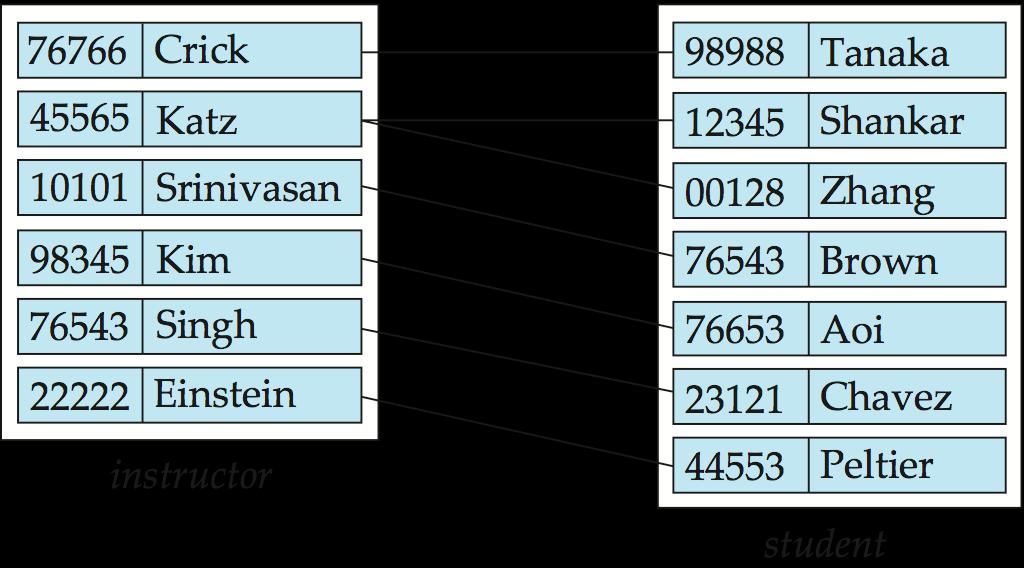
6 Relationship Set advisor 7.6
 An attribute can also be property of a relationship set.")

7 Relationship Sets (Cont.) An attribute can also be property of a relationship set. For instance, the advisor relationship set between entity sets instructor and student may have the attribute date which tracks when the student started being associated with the advisor 7.7
8 Degree of a Relationship Set binary relationship involve two entity sets (or degree two). most relationship sets in a database system are binary. Relationships between more than two entity sets are rare. Most relationships are binary. (More on this later.) Example: students work on research projects under the guidance of an instructor. relationship proj_guide is a ternary relationship between instructor, student, and project 7.8
9 Attributes An entity is represented by a set of attributes, that is descriptive properties possessed by all members of an entity set. Example: instructor = (ID, name, street, city, salary ) course= (course_id, title, credits) Domain the set of permitted values for each attribute Attribute types: Simple and composite attributes. Single-valued and multivalued attributes Example: multivalued attribute: phone_numbers Derived attributes Can be computed from other attributes Example: age, given date_of_birth 7.9

10 Composite Attributes 7.10
11 Mapping Cardinality Constraints Express the number of entities to which another entity can be associated via a relationship set. Most useful in describing binary relationship sets. For a binary relationship set the mapping cardinality must be one of the following types: One to one One to many Many to one Many to many 7.11
12 Mapping Cardinalities One to one One to many Note: Some elements in A and B may not be mapped to any elements in the other set 7.12
13 Mapping Cardinalities Many to one Many to many Note: Some elements in A and B may not be mapped to any elements in the other set 7.13
14 Keys A super key of an entity set is a set of one or more attributes whose values uniquely determine each entity. A candidate key of an entity set is a minimal super key ID is candidate key of instructor course_id is candidate key of course Although several candidate keys may exist, one of the candidate keys is selected to be the primary key. 7.14
15 Keys for Relationship Sets The combination of primary keys of the participating entity sets forms a super key of a relationship set. (s_id, i_id) is the super key of advisor NOTE: this means a pair of entity sets can have at most one relationship in a particular relationship set. Example: if we wish to track multiple meeting dates between a student and her advisor, we cannot assume a relationship for each meeting. We can use a multivalued attribute though Must consider the mapping cardinality of the relationship set when deciding what are the candidate keys Need to consider semantics of relationship set in selecting the primary key in case of more than one candidate key 7.15
16 Redundant Attributes Suppose we have entity sets instructor, with attributes including dept_name department and a relationship inst_dept relating instructor and department Attribute dept_name in entity instructor is redundant since there is an explicit relationship inst_dept which relates instructors to departments The attribute replicates information present in the relationship, and should be removed from instructor BUT: when converting back to tables, in some cases the attribute gets reintroduced, as we will see. 7.16
17 E-R Diagrams Rectangles represent entity sets. Diamonds represent relationship sets. Attributes listed inside entity rectangle Underline indicates primary key attributes 7.17
18 Entity With Composite, Multivalued, and Derived Attributes 7.18

19 Relationship Sets with Attributes 7.19


20 Roles Entity sets of a relationship need not be distinct Each occurrence of an entity set plays a role in the relationship The labels course_id and prereq_id are called roles. 7.20
21 Cardinality Constraints We express cardinality constraints by drawing either a directed line ( ), signifying one, or an undirected line ( ), signifying many, between the relationship set and the entity set. One-to-one relationship: A student is associated with at most one instructor via the relationship advisor A student is associated with at most one department via stud_dept 7.21

22 One-to-One Relationship one-to-one relationship between an instructor and a student an instructor is associated with at most one student via advisor and a student is associated with at most one instructor via advisor 7.22


23 One-to-Many Relationship one-to-many relationship between an instructor and a student an instructor is associated with several (including 0) students via advisor a student is associated with at most one instructor via advisor, 7.23
 instructors via advisor 7.")
24 Many-to-One Relationships In a many-to-one relationship between an instructor and a student, an instructor is associated with at most one student via advisor, and a student is associated with several (including 0) instructors via advisor 7.24
25 Many-to-Many Relationship An instructor is associated with several (possibly 0) students via advisor A student is associated with several (possibly 0) instructors via advisor 7.25
26 Participation of an Entity Set in a Relationship Set Total participation (indicated by double line): every entity in the entity set participates in at least one relationship in the relationship set E.g., participation of section in sec_course is total every section must have an associated course Partial participation: some entities may not participate in any relationship in the relationship set Example: participation of instructor in advisor is partial 7.26

27 Alternative Notation for Cardinality Limits Cardinality limits can also express participation constraints 7.27

28 E-R Diagram with a Ternary Relationship 7.28
29 Cardinality Constraints on Ternary Relationship We allow at most one arrow out of a ternary (or greater degree) relationship to indicate a cardinality constraint E.g., an arrow from proj_guide to instructor indicates each student has at most one guide for a project If there is more than one arrow, there are two ways of defining the meaning. E.g., a ternary relationship R between A, B and C with arrows to B and C could mean 1. each A entity is associated with a unique entity from B and C or 2. each pair of entities from (A, B) is associated with a unique C entity, and each pair (A, C) is associated with a unique B Each alternative has been used in different formalisms To avoid confusion we outlaw more than one arrow 7.29
30 How about doing an ER design interactively on the board? Suggest an application to be modeled. Database System Concepts, 6 th Ed. See for conditions on re-use
31 Weak Entity Sets An entity set that does not have a primary key is referred to as a weak entity set. The existence of a weak entity set depends on the existence of a identifying entity set It must relate to the identifying entity set via a total, one-to-many relationship set from the identifying to the weak entity set Identifying relationship depicted using a double diamond The discriminator (or partial key) of a weak entity set is the set of attributes that distinguishes among all the entities of a weak entity set. The primary key of a weak entity set is formed by the primary key of the strong entity set on which the weak entity set is existence dependent, plus the weak entity set s discriminator. 7.31
32 Weak Entity Sets (Cont.) We underline the discriminator of a weak entity set with a dashed line. We put the identifying relationship of a weak entity in a double diamond. Primary key for section (course_id, sec_id, semester, year) 7.32
33 Weak Entity Sets (Cont.) Note: the primary key of the strong entity set is not explicitly stored with the weak entity set, since it is implicit in the identifying relationship. If course_id were explicitly stored, section could be made a strong entity, but then the relationship between section and course would be duplicated by an implicit relationship defined by the attribute course_id common to course and section 7.33

34 E-R Diagram for a University Enterprise 7.34
35 Reduction to Relational Schemas 7.35
36 Reduction to Relation Schemas Entity sets and relationship sets can be expressed uniformly as relation schemas that represent the contents of the database. A database which conforms to an E-R diagram can be represented by a collection of schemas. For each entity set and relationship set there is a unique schema that is assigned the name of the corresponding entity set or relationship set. Each schema has a number of columns (generally corresponding to attributes), which have unique names. 7.36
37 Representing Entity Sets With Simple Attributes A strong entity set reduces to a schema with the same attributes student(id, name, tot_cred) A weak entity set becomes a table that includes a column for the primary key of the identifying strong entity set section ( course_id, sec_id, sem, year ) 7.37
38 Representing Relationship Sets A many-to-many relationship set is represented as a schema with attributes for the primary keys of the two participating entity sets, and any descriptive attributes of the relationship set. Example: schema for relationship set advisor advisor = (s_id, i_id) 7.38

39 Redundancy of Schemas Many-to-one and one-to-many relationship sets that are total on the many-side can be represented by adding an extra attribute to the many side, containing the primary key of the one side Example: Instead of creating a schema for relationship set inst_dept, add an attribute dept_name to the schema arising from entity set instructor 7.39
40 Redundancy of Schemas (Cont.) For one-to-one relationship sets, either side can be chosen to act as the many side That is, extra attribute can be added to either of the tables corresponding to the two entity sets If participation is partial on the many side, replacing a schema by an extra attribute in the schema corresponding to the many side could result in null values The schema corresponding to a relationship set linking a weak entity set to its identifying strong entity set is redundant. Example: The section schema already contains the attributes that would appear in the sec_course schema 7.40
41 Composite and Multivalued Attributes Composite attributes are flattened out by creating a separate attribute for each component attribute Example: given entity set instructor with composite attribute name with component attributes first_name and last_name the schema corresponding to the entity set has two attributes name_first_name and name_last_name Prefix omitted if there is no ambiguity Ignoring multivalued attributes, extended instructor schema is instructor(id, first_name, middle_initial, last_name, street_number, street_name, apt_number, city, state, zip_code, date_of_birth) 7.41
42 Composite and Multivalued Attributes A multivalued attribute M of an entity E is represented by a separate schema EM Schema EM has attributes corresponding to the primary key of E and an attribute corresponding to multivalued attribute M Example: Multivalued attribute phone_number of instructor is represented by a schema: inst_phone= ( ID, phone_number) Each value of the multivalued attribute maps to a separate tuple of the relation on schema EM For example, an instructor entity with primary key and phone numbers and maps to two tuples: (22222, ) and (22222, ) 7.42
 Special case:entity time_slot has only one attribute other than the primary-key attribute, and that attribute is multivalued Optimization: Don t create the relation corresponding to the entity,")
43 Multivalued Attributes (Cont.) Special case:entity time_slot has only one attribute other than the primary-key attribute, and that attribute is multivalued Optimization: Don t create the relation corresponding to the entity, just create the one corresponding to the multivalued attribute time_slot(time_slot_id, day, start_time, end_time) Caveat: time_slot attribute of section (from sec_time_slot) cannot be a foreign key due to this optimization 7.43

")
44 Design Issues Use of entity sets vs. attributes Use of phone as an entity allows extra information about phone numbers (plus multiple phone numbers) 7.44

45 Design Issues Use of entity sets vs. relationship sets Possible guideline is to designate a relationship set to describe an action that occurs between entities 7.45
46 Design Issues Binary versus n-ary relationship sets Although it is possible to replace any nonbinary (n-ary, for n > 2) relationship set by a number of distinct binary relationship sets, a n-ary relationship set shows more clearly that several entities participate in a single relationship. Placement of relationship attributes e.g., attribute date as attribute of advisor or as attribute of student 7.46
47 Binary Vs. Non-Binary Relationships Some relationships that appear to be non-binary may be better represented using binary relationships E.g., A ternary relationship parents, relating a child to his/her father and mother, is best replaced by two binary relationships, father and mother Using two binary relationships allows partial information (e.g., only mother being know) But there are some relationships that are naturally non-binary Example: proj_guide 7.47

48 Converting Non-Binary Relationships to Binary Form In general, any non-binary relationship can be represented using binary relationships by creating an artificial entity set. Replace R between entity sets A, B and C by an entity set E, and three relationship sets: 1. R A, relating E and A 2. R B, relating E and B 3. R C, relating E and C Create a special identifying attribute for E Add any attributes of R to E For each relationship (a i, b i, c i ) in R, create 1. a new entity e i in the entity set E 2. add (e i, a i ) to R A 3. add (e i, b i ) to R B 4. add (e i, c i ) to R C 7.48
 Also need to translate constraints Translating all constraints may not be possible There may be instances in the translated schema that cannot correspond to any instance of R Exercise: add")
49 Converting Non-Binary Relationships (Cont.) Also need to translate constraints Translating all constraints may not be possible There may be instances in the translated schema that cannot correspond to any instance of R Exercise: add constraints to the relationships R A, R B and R C to ensure that a newly created entity corresponds to exactly one entity in each of entity sets A, B and C We can avoid creating an identifying attribute by making E a weak entity set (described shortly) identified by the three relationship sets 7.49
50 Extended ER Features 7.50
51 Extended E-R Features: Specialization Top-down design process; we designate subgroupings within an entity set that are distinctive from other entities in the set. These subgroupings become lower-level entity sets that have attributes or participate in relationships that do not apply to the higher-level entity set. Depicted by a triangle component labeled ISA (E.g., instructor is a person). Attribute inheritance a lower-level entity set inherits all the attributes and relationship participation of the higher-level entity set to which it is linked. 7.51

52 Specialization Example 7.52
53 Extended ER Features: Generalization A bottom-up design process combine a number of entity sets that share the same features into a higher-level entity set. Specialization and generalization are simple inversions of each other; they are represented in an E-R diagram in the same way. The terms specialization and generalization are used interchangeably. 7.53
54 Specialization and Generalization (Cont.) Can have multiple specializations of an entity set based on different features. E.g., permanent_employee vs. temporary_employee, in addition to instructor vs. secretary Each particular employee would be a member of one of permanent_employee or temporary_employee, and also a member of one of instructor, secretary The ISA relationship also referred to as superclass - subclass relationship 7.54
55 Design Constraints on a Specialization/Generalization Constraint on which entities can be members of a given lower-level entity set. condition-defined Example: all customers over 65 years are members of seniorcitizen entity set; senior-citizen ISA person. user-defined Constraint on whether or not entities may belong to more than one lowerlevel entity set within a single generalization. Disjoint an entity can belong to only one lower-level entity set Noted in E-R diagram by having multiple lower-level entity sets link to the same triangle Overlapping an entity can belong to more than one lower-level entity set 7.55
56 Design Constraints on a Specialization/Generalization (Cont.) Completeness constraint -- specifies whether or not an entity in the higher-level entity set must belong to at least one of the lowerlevel entity sets within a generalization. total: an entity must belong to one of the lower-level entity sets partial: an entity need not belong to one of the lower-level entity sets 7.56

57 Aggregation Consider the ternary relationship proj_guide, which we saw earlier Suppose we want to record evaluations of a student by a guide on a project 7.57
58 Aggregation (Cont.) Relationship sets eval_for and proj_guide represent overlapping information Every eval_for relationship corresponds to a proj_guide relationship However, some proj_guide relationships may not correspond to any eval_for relationships So we can t discard the proj_guide relationship Eliminate this redundancy via aggregation Treat relationship as an abstract entity Allows relationships between relationships Abstraction of relationship into new entity 7.58
59 Aggregation (Cont.) Without introducing redundancy, the following diagram represents: A student is guided by a particular instructor on a particular project A student, instructor, project combination may have an associated evaluation 7.59
60 Representing Specialization via Schemas Method 1: Form a schema for the higher-level entity Form a schema for each lower-level entity set, include primary key of higher-level entity set and local attributes schema person student employee attributes ID, name, street, city ID, tot_cred ID, salary Drawback: getting information about, an employee requires accessing two relations, the one corresponding to the low-level schema and the one corresponding to the high-level schema 7.60
61 Representing Specialization as Schemas (Cont.) Method 2: Form a schema for each entity set with all local and inherited attributes schema attributes person ID, name, street, city student ID, name, street, city, tot_cred employee ID, name, street, city, salary If specialization is total, the schema for the generalized entity set (person) not required to store information Can be defined as a view relation containing union of specialization relations But explicit schema may still be needed for foreign key constraints Drawback: name, street and city may be stored redundantly for people who are both students and employees 7.61
62 Schemas Corresponding to Aggregation To represent aggregation, create a schema containing primary key of the aggregated relationship, the primary key of the associated entity set any descriptive attributes 7.62
63 Schemas Corresponding to Aggregation (Cont.) For example, to represent aggregation manages between relationship works_on and entity set manager, create a schema eval_for (s_id, project_id, i_id, evaluation_id) Schema proj_guide is redundant provided we are willing to store null values for attribute manager_name in relation on schema manages 7.63
64 E-R Design Decisions The use of an attribute or entity set to represent an object. Whether a real-world concept is best expressed by an entity set or a relationship set. The use of a ternary relationship versus a pair of binary relationships. The use of a strong or weak entity set. The use of specialization/generalization contributes to modularity in the design. The use of aggregation can treat the aggregate entity set as a single unit without concern for the details of its internal structure. 7.64
65 How about doing another ER design interactively on the board? Database System Concepts, 6 th Ed. See for conditions on re-use

66 Summary of Symbols Used in E-R Notation 7.66
 7.")
67 Symbols Used in E-R Notation (Cont.) 7.67

68 Alternative ER Notations Chen, IDE1FX, 7.68
 7.")
69 Alternative ER Notations Chen IDE1FX (Crows feet notation) 7.69
70 UML UML: Unified Modeling Language UML has many components to graphically model different aspects of an entire software system UML Class Diagrams correspond to E-R Diagram, but several differences. 7.70

71 ER vs. UML Class Diagrams *Note reversal of position in cardinality constraint depiction 7.71

72 ER vs. UML Class Diagrams ER Diagram Notation Equivalent in UML *Generalization can use merged or separate arrows independent of disjoint/overlapping 7.72
73 UML Class Diagrams (Cont.) Binary relationship sets are represented in UML by just drawing a line connecting the entity sets. The relationship set name is written adjacent to the line. The role played by an entity set in a relationship set may also be specified by writing the role name on the line, adjacent to the entity set. The relationship set name may alternatively be written in a box, along with attributes of the relationship set, and the box is connected, using a dotted line, to the line depicting the relationship set. 7.73
74 Homework 7.15, 7.17, 7.26 DB_ 学号 _ 姓名 _ 章.docx 7.74
75 End of Chapter 7 Database System Concepts, 6 th Ed. See for conditions on re-use
Chapter 7: Entity-Relationship Model
 Chapter 7: Entity-Relationship Model Database System Concepts, 6 th Ed. See www.db-book.com for conditions on re-use Chapter 7: Entity-Relationship Model Design Process Modeling Constraints E-R Diagram
Chapter 7: Entity-Relationship Model
 Chapter 7: Entity-Relationship Model Database System Concepts, 6 th Ed. See www.db-book.com for conditions on re-use Chapter 7: Entity-Relationship Model Design Process Modeling Constraints E-R Diagram
Roadmap of This Lecture. Weak Entity Sets Extended E-R Features Reduction to Relation Schemas Database Design UML*
 E-R Model (II) 1 Roadmap of This Lecture Weak Entity Sets Extended E-R Features Reduction to Relation Schemas Database Design UML* 2 Weak Entity Sets An entity set that does not have a primary key is referred
Chapter 7: Entity-Relationship Model
 Chapter 7: Entity-Relationship Model, 7th Ed. See www.db-book.com for conditions on re-use Chapter 7: Entity-Relationship Model Design Process Modeling Constraints E-R Diagram Design Issues Weak Entity
The En'ty Rela'onship Model
 The En'ty Rela'onship Model Debapriyo Majumdar DBMS Fall 2016 Indian Statistical Institute Kolkata Slides re-used, with minor modification, from Silberschatz, Korth and Sudarshan www.db-book.com Outline
Chapter 7: Entity-Relationship Model. Chapter 7: Entity-Relationship Model
 Chapter 7: Entity-Relationship Model Database System Concepts, 6 th Ed. See www.db-book.com for conditions on re-use Chapter 7: Entity-Relationship Model Design Process Modeling Constraints E-R Diagram
Unit1: Introduction. Database System Concepts, 6 th Ed. Silberschatz, Korth and Sudarshan See for conditions on re-use
 Unit1: Introduction Database System Concepts, 6 th Ed. See www.db-book.com for conditions on re-use Outline Introduction to Database Management Systems, Purpose of Database Systems, Database-System Applications,
Chapter 6: Entity-Relationship Model
 Chapter 6: Entity-Relationship Model Database System Concepts, 5th Ed. See www.db-book.com for conditions on re-use Chapter 6: Entity-Relationship Model Design Process Modeling Constraints E-R Diagram
Chapter 2: Entity-Relationship Model
 Chapter 2: Entity-Relationship Model! Entity Sets! Relationship Sets! Design Issues! Mapping Constraints! Keys! E-R Diagram! Extended E-R Features! Design of an E-R Database Schema! Reduction of an E-R
Chapter 6: Entity-Relationship Model
 Chapter 6: Entity-Relationship Model Database System Concepts, 5th Ed. See www.db-book.com for conditions on re-use Chapter 6: Entity-Relationship Model Design Process Modeling Constraints E-R Diagram
Unit I. By Prof.Sushila Aghav MIT
 Unit I By Prof.Sushila Aghav MIT Introduction The Need for Databases Data Models Relational Databases Database Design Storage Manager Query Processing Transaction Manager DBMS Applications DBMS contains
Lecture 10 - Chapter 7 Entity Relationship Model
 CMSC 461, Database Management Systems Spring 2018 Lecture 10 - Chapter 7 Entity Relationship Model These slides are based on Database System Concepts 6th edition book and are a modified version of the
CS425 Fall 2013 Boris Glavic Chapter 7: Entity-Relationship Model!
 CS425 Fall 2013 Boris Glavic Chapter 7: Entity-Relationship Model! Partially taken from! Klaus R. Dittrich! modified from:! Database System Concepts, 6 th Ed.! Silberschatz, Korth and Sudarshan See www.db-book.com
Chapter 6: Entity-Relationship Model
 Chapter 6: Entity-Relationship Model Database System Concepts, 5th Ed. See www.db-book.com for conditions on re-use Chapter 6: Entity-Relationship Model Design Process Modeling Constraints E-R Diagram
Entity-Relationship Model
 Entity-Relationship Model Data Models High-level or conceptual data models provide concepts that are close to the way many users perceive data, whereas low-level or physical data models provide concepts
Other Relational Languages
 Other Relational Languages 1 Tuple Relational Calculus A nonprocedural query language, where each query is of the form {t P (t ) } It is the set of all tuples t such that predicate P is true for t t is
Chapter 2: Entity-Relationship Model. Entity Sets. Entity Sets customer and loan. Attributes. Relationship Sets. A database can be modeled as:
 Chapter 2: Entity-Relationship Model Entity Sets Entity Sets Relationship Sets Design Issues Mapping Constraints Keys E-R Diagram Extended E-R Features Design of an E-R Database Schema Reduction of an
Chapter 6: Entity-Relationship Model
 Chapter 6: Entity-Relationship Model Database System Concepts, 5th Ed. See www.db-book.com for conditions on re-use Chapter 6: Entity-Relationship Model Design Process Modeling Constraints E-R Diagram
Database Design and the E-R Model (7.4, )
") CSL 451 Introduction to Database Systems Database Design and the E-R Model (7.4, 7.6-7.8) Department of Computer Science and Engineering Indian Institute of Technology Ropar Narayanan (CK) Chatapuram Krishnan!
CSL 451 Introduction to Database Systems Database Design and the E-R Model (7.4, 7.6-7.8) Department of Computer Science and Engineering Indian Institute of Technology Ropar Narayanan (CK) Chatapuram Krishnan!
Chapter 7: Entity-Relationship Model. CS425 Fall 2016 Boris Glavic. Chapter 7: Entity-Relationship Model. Database Design.
 Chapter 7: ntity-elationship Model Design Process CS425 Fall 2013 Boris Glavic Chapter 7: ntity-elationship Model Modeling Constraints - Diagram Design Issues Weak ntity Sets xtended - Features Design
ER to Relational Model. Professor Jessica Lin
 ER to Relational Model Professor Jessica Lin 1 Reduction to Relation Schemas Entity sets and relationship sets can be expressed uniformly as relation schemas that represent the contents of the database.
Chapter 6: Entity-Relationship Model. E-R Diagrams
 Chapter 6: Entity-Relationship Model A database can be modeled as: a collection of entities, relationship among entities. An entity is an object that exists and is distinguishable from other objects. Example:
Chapter 6: Entity-Relationship Model. The Next Step: Designing DB Schema. Identifying Entities and their Attributes. The E-R Model.
 Chapter 6: Entity-Relationship Model The Next Step: Designing DB Schema Our Story So Far: Relational Tables Databases are structured collections of organized data The Relational model is the most common
The Next Step: Designing DB Schema. Chapter 6: Entity-Relationship Model. The E-R Model. Identifying Entities and their Attributes.
 Chapter 6: Entity-Relationship Model Our Story So Far: Relational Tables Databases are structured collections of organized data The Relational model is the most common data organization model The Relational
A database can be modeled as: + a collection of entities, + a set of relationships among entities.
 The Relational Model Lecture 2 The Entity-Relationship Model and its Translation to the Relational Model Entity-Relationship (ER) Model + Entity Sets + Relationship Sets + Database Design Issues + Mapping
Lecture 14 of 42. E-R Diagrams, UML Notes: PS3 Notes, E-R Design. Thursday, 15 Feb 2007
 Lecture 14 of 42 E-R Diagrams, UML Notes: PS3 Notes, E-R Design Thursday, 15 February 2007 William H. Hsu Department of Computing and Information Sciences, KSU KSOL course page: http://snipurl.com/va60
6.1 RELATIONSHIP CONCEPTS
 1 SYLLABUS 6.1 Basic Entity Relationship Concepts: Entities, Relationship, Attributes 6.2 E R Diagram symbols 6.3 Conversion of Entity Relationship Model into Relations 6.4 Problems with Enitty Relationship
Intro to DB CHAPTER 6
 Intro to DB CHAPTER 6 DATABASE DESIGN &THEER E-R MODEL Chapter 6. Entity Relationship Model Design Process Modeling Constraints E-R Diagram Design Issues Weak Entity Sets Extended E-R Features Design of
Design Process Modeling Constraints E-R Diagram Design Issues Weak Entity Sets Extended E-R Features Design of the Bank Database Reduction to
 Design Process Modeling Constraints E-R Diagram Design Issues Weak Entity Sets Extended E-R Features Design of the Bank Database Reduction to Relation Schemas Database Design UML A database can be modeled
Entity-Relationship Modelling. Entities Attributes Relationships Mapping Cardinality Keys Reduction of an E-R Diagram to Tables
 Entity-Relationship Modelling Entities Attributes Relationships Mapping Cardinality Keys Reduction of an E-R Diagram to Tables 1 Entity Sets A enterprise can be modeled as a collection of: entities, and
Unit I. Introduction to Database. Prepared By: Prof.Sushila Aghav. Ref.Database Concepts by Korth
 Unit I Introduction to Database Prepared By: Prof.Sushila Aghav Ref.Database Concepts by Korth Contents Database Concepts Data Models & Types Relational Database-R Model(Table) ER Modeling Concepts of
2. E-R Model. Entity Sets Relationship Sets Attributes
 3. E R Model 2. E-R Model Entity-Relationship Model Graphical Representation of Database Equivalent to Flow-Chart in Programming It makes easy to understand Database Prior Step to implement Actual Database
Example: specific person, company, event, plant
 A database can be modeled as: a collection of entities, relationship among entities. An entity is an object that exists and is distinguishable from other objects. Example: specific person, company, event,
UNIT II A. ENTITY RELATIONSHIP MODEL
 UNIT II A. ENTITY RELATIONSHIP MODEL Agenda En0ty & En0ty Sets A6ributes Rela0onship & Rela0onship Sets Constraints Mapping Cardinali0es, Par0cipa0on Constraints, Keys E-R Diagrams & Design of Database
CSIT5300: Advanced Database Systems
 CSIT5300: Advanced Database Systems L01: Entity Relationship (ER) Model Dr. Kenneth LEUNG Department of Computer Science and Engineering The Hong Kong University of Science and Technology Hong Kong SAR,
COMP Instructor: Dimitris Papadias WWW page:
 COMP 5311 Instructor: Dimitris Papadias WWW page: http://www.cse.ust.hk/~dimitris/5311/5311.html Textbook Database System Concepts, A. Silberschatz, H. Korth, and S. Sudarshan. Reference Database Management
VARDHAMAN COLLEGE OF ENGINEERING Shamshabad , Hyderabad B.Tech. CSE IV Semester (VCE - R11) T P C 3+1* -- 4 (A1511) DATABASE MANAGEMENT SYSTEMS
 T P C 3+1* -- 4 (A1511) DATABASE MANAGEMENT SYSTEMS") 1 VARDHAMAN COLLEGE OF ENGINEERING Shamshabad 501 218, Hyderabad B.Tech. CSE IV Semester (VCE - R11) T P C 3+1* -- 4 (A1511) DATABASE MANAGEMENT SYSTEMS UNIT - I INTRODUCTION: History of database systems,
1 VARDHAMAN COLLEGE OF ENGINEERING Shamshabad 501 218, Hyderabad B.Tech. CSE IV Semester (VCE - R11) T P C 3+1* -- 4 (A1511) DATABASE MANAGEMENT SYSTEMS UNIT - I INTRODUCTION: History of database systems,
Chapter 9: Relational DB Design byer/eer to Relational Mapping Relational Database Design Using ER-to- Relational Mapping Mapping EER Model
 Chapter 9: Relational DB Design byer/eer to Relational Mapping Relational Database Design Using ER-to- Relational Mapping Mapping EER Model Constructs to Relations Relational Database Design by ER- and
CMPT 354 Database Systems I
 CMPT 354 Database Systems I Chapter 2 Entity Relationship Data Modeling Data models A data model is the specifications for designing data organization in a system. Specify database schema using a data
ER to Relational Mapping
 ER to Relational Mapping 1 / 19 ER to Relational Mapping Step 1: Strong Entities Step 2: Weak Entities Step 3: Binary 1:1 Relationships Step 4: Binary 1:N Relationships Step 5: Binary M:N Relationships
MIS Database Systems Entity-Relationship Model.
 MIS 335 - Database Systems Entity-Relationship Model http://www.mis.boun.edu.tr/durahim/ Ahmet Onur Durahim Learning Objectives Database Design Main concepts in the ER model? ER Diagrams Database Design
CS425 Fall 2016 Boris Glavic Chapter 2: Intro to Relational Model
 CS425 Fall 2016 Boris Glavic Chapter 2: Intro to Relational Model Modifies from: Database System Concepts, 6 th Ed. See www.db-book.com for conditions on re-use Textbook: Chapter 2 2.2 Example of a Relation
Chapter 2 ENTITY RELATIONSHIP MODEL
 INTRODUCTION Chapter 2 ENTITY RELATIONSHIP MODEL Data model is used to describe data, data relationship and constraints on data. A number of different data models have proposed. They can broadly be classified
Database Systems. Lecture2:E-R model. Juan Huo( 霍娟 )
") Database Systems Lecture2:E-R model Juan Huo( 霍娟 ) Reference slides: http://www.cs.wisc.edu/ dbbook Berkeley, Professor Eben Haber,Professor Mary Roth Review: Benefits of a DBMS 1. Data independence applications
Database Systems Lecture2:E-R model Juan Huo( 霍娟 ) Reference slides: http://www.cs.wisc.edu/ dbbook Berkeley, Professor Eben Haber,Professor Mary Roth Review: Benefits of a DBMS 1. Data independence applications
Major components of ER diagram Practices
 Major components of ER diagram Practices 1 1976 proposed by Peter Chen ER diagram is widely used in database design Represent conceptual level of a database system Describe things and their relationships
 0. Database Systems 1.1 Introduction to DBMS Information is one of the most valuable resources in this information age! How do we effectively and efficiently manage this information? - How does Wal-Mart
Overview of Database Design Process Example Database Application (COMPANY) ER Model Concepts
 ER Model Concepts") Chapter Outline Overview of Database Design Process Example Database Application (COMPANY) ER Model Concepts Entities and Attributes Entity Types, Value Sets, and Key Attributes Relationships and Relationship
Chapter Outline Overview of Database Design Process Example Database Application (COMPANY) ER Model Concepts Entities and Attributes Entity Types, Value Sets, and Key Attributes Relationships and Relationship
Using High-Level Conceptual Data Models for Database Design A Sample Database Application Entity Types, Entity Sets, Attributes, and Keys
 Chapter 7: Data Modeling Using the Entity- Relationship (ER) Model Using High-Level Conceptual Data Models for Database Design A Sample Database Application Entity Types, Entity Sets, Attributes, and Keys
Chapter Outline. Note 1. Overview of Database Design Process Example Database Application (COMPANY) ER Model Concepts
 ER Model Concepts") Chapter Outline Overview of Database Design Process Example Database Application (COMPANY) ER Model Concepts Entities and Attributes Entity Types, Value Sets, and Key Attributes Relationships and Relationship
Chapter Outline Overview of Database Design Process Example Database Application (COMPANY) ER Model Concepts Entities and Attributes Entity Types, Value Sets, and Key Attributes Relationships and Relationship
The Entity-Relationship Model. Steps in Database Design
 The Entity-Relationship Model Steps in Database Design 1) Requirement Analysis Identify the data that needs to be stored data requirements Identify the operations that need to be executed on the data functional
Module 2 : Entity-Relationship Model 15
 Module 2 : Entity-Relationship Model 15 Module-02 Entity Relationship Data Model 2.1 Motivation Data modeling is an essential step in the process of creating any Database Application. It helps Database
Topic 5: Mapping of EER Diagrams to Relations
 Topic 5: Mapping of EER Diagrams to Relations Olaf Hartig olaf.hartig@liu.se Recall: DB Design Process 2 Running Example 3 Algorithm for Mapping from the ER Model to the Relational Model Step 1: Map Regular
Entity Relationship Data Model. Slides by: Shree Jaswal
 Entity Relationship Data Model Slides by: Shree Jaswal Topics: Conceptual Modeling of a database, The Entity-Relationship (ER) Model, Entity Types, Entity Sets, Attributes, and Keys, Relationship Types,
Conceptual Data Models for Database Design
 Conceptual Data Models for Database Design Entity Relationship (ER) Model The most popular high-level conceptual data model is the ER model. It is frequently used for the conceptual design of database
Conceptual Data Modeling
 Conceptual Data odeling A data model is a way to describe the structure of the data. In models that are implemented it includes a set of operations that manipulate the data. A Data odel is a combination
E-R Model. Hi! Here in this lecture we are going to discuss about the E-R Model.
 E-R Model Hi! Here in this lecture we are going to discuss about the E-R Model. What is Entity-Relationship Model? The entity-relationship model is useful because, as we will soon see, it facilitates communication
Chapter (4) Enhanced Entity-Relationship and Object Modeling
 Enhanced Entity-Relationship and Object Modeling") Chapter (4) Enhanced Entity-Relationship and Object Modeling Objectives Concepts of subclass and superclass and the related concepts of specialization and generalization. Concept of category, which is
Chapter (4) Enhanced Entity-Relationship and Object Modeling Objectives Concepts of subclass and superclass and the related concepts of specialization and generalization. Concept of category, which is
Database Management Systems LECTURE NOTES 2
 Database Management Systems LECTURE NOTES 2 Relation: A table; Tuple: A row in a table; Attribute: A column in a table Degree: number of attributes; Cardinality: number of tuples Entity and Entity Sets:
CSIT5300: Advanced Database Systems
 CSIT5300: Advanced Database Systems L02: Relational Data Model Dr. Kenneth LEUNG Department of Computer Science and Engineering The Hong Kong University of Science and Technology Hong Kong SAR, China kwtleung@cse.ust.hk
Chapter 8: Enhanced ER Model
 Chapter 8: Enhanced ER Model Subclasses, Superclasses, and Inheritance Specialization and Generalization Constraints and Characteristics of Specialization and Generalization Hierarchies Modeling of UNION
LELCTURE 4: ENHANCED ENTITY-RELATIONSHIP MODELING (EER)
") LELCTURE 4: ENHANCED ENTITY-RELATIONSHIP MODELING (EER) Ref. Chapter12 from Database Systems: A Practical Approach to Design, Implementation and Management. Thomas Connolly, Carolyn Begg. IS220 : D at
LELCTURE 4: ENHANCED ENTITY-RELATIONSHIP MODELING (EER) Ref. Chapter12 from Database Systems: A Practical Approach to Design, Implementation and Management. Thomas Connolly, Carolyn Begg. IS220 : D at
FINAL EXAM REVIEW. CS121: Introduction to Relational Database Systems Fall 2018 Lecture 27
 FINAL EXAM REVIEW CS121: Introduction to Relational Database Systems Fall 2018 Lecture 27 Final Exam Overview 2 Unlimited time, multiple sittings Open book, notes, MySQL database, etc. (the usual) Primary
Database Management System (15ECSC208) UNIT I: Chapter 2: Relational Data Model and Relational Algebra
 UNIT I: Chapter 2: Relational Data Model and Relational Algebra") Database Management System (15ECSC208) UNIT I: Chapter 2: Relational Data Model and Relational Algebra Relational Data Model and Relational Constraints Part 1 A simplified diagram to illustrate the main
Database Management System (15ECSC208) UNIT I: Chapter 2: Relational Data Model and Relational Algebra Relational Data Model and Relational Constraints Part 1 A simplified diagram to illustrate the main
Weak Entity Sets. A weak entity is an entity that cannot exist in a database unless another type of entity also exists in that database.
 Weak Entity Sets A weak entity is an entity that cannot exist in a database unless another type of entity also exists in that database. Weak entity meets two conditions Existence-dependent Cannot exist
Database Systems ER Model. A.R. Hurson 323 CS Building
 ER Model A.R. Hurson 323 CS Building Database Design Data model is a group of concepts that helps to specify the structure of a database and a set of associated operations allowing data retrieval and data
Conceptual Database Design. COSC 304 Introduction to Database Systems. Entity-Relationship Modeling. Entity-Relationship Modeling
 COSC 304 Introduction to Database Systems Entity-Relationship Modeling Dr. Ramon Lawrence University of British Columbia Okanagan ramon.lawrence@ubc.ca Conceptual Database Design Conceptual database design
Enhanced Entity- Relationship Models (EER)
") Enhanced Entity- Relationship Models (EER) LECTURE 3 Dr. Philipp Leitner philipp.leitner@chalmers.se @xleitix LECTURE 3 Covers Small part of Chapter 3 Chapter 4 Please read this up until next lecture!
Enhanced Entity- Relationship Models (EER) LECTURE 3 Dr. Philipp Leitner philipp.leitner@chalmers.se @xleitix LECTURE 3 Covers Small part of Chapter 3 Chapter 4 Please read this up until next lecture!
Database Principles: Fundamentals of Design, Implementation, and Management Tenth Edition. Chapter 7 Data Modeling with Entity Relationship Diagrams
 Database Principles: Fundamentals of Design, Implementation, and Management Tenth Edition Chapter 7 Data Modeling with Entity Relationship Diagrams Objectives In this chapter, students will learn: The
CSCC43H: Introduction to Databases
 CSCC43H: Introduction to Databases Lecture 2 Wael Aboulsaadat Acknowledgment: these slides are partially based on Prof. Garcia-Molina & Prof. Ullman slides accompanying the course s textbook. CSCC43: Introduction
A l Ain University Of Science and Technology
 A l Ain University Of Science and Technology 4 Handout(4) Database Management Principles and Applications The Entity Relationship (ER) Model http://alainauh.webs.com/ 1 In this chapter, you will learn:
More on the Chen Notation
 More on the Chen Notation Reference: http://www.vertabelo.com/blog/technical-articles/chen-erd-notation Peter Chen, who developed entity-relationship modeling and published his work in 1976, was one of
Chapter 8: Relational Database Design
 Chapter 8: Relational Database Design Database System Concepts, 6 th Ed. See www.db-book.com for conditions on re-use Chapter 8: Relational Database Design Features of Good Relational Design Atomic Domains
1/24/2012. Chapter 7 Outline. Chapter 7 Outline (cont d.) CS 440: Database Management Systems
 CS 440: Database Management Systems") CS 440: Database Management Systems Chapter 7 Outline Using High-Level Conceptual Data Models for Database Design A Sample Database Application Entity Types, Entity Sets, Attributes, and Keys Relationship
CS 440: Database Management Systems Chapter 7 Outline Using High-Level Conceptual Data Models for Database Design A Sample Database Application Entity Types, Entity Sets, Attributes, and Keys Relationship
Chapter 4. Enhanced Entity- Relationship Modeling. Enhanced-ER (EER) Model Concepts. Subclasses and Superclasses (1)
 Model Concepts. Subclasses and Superclasses (1)") Chapter 4 Enhanced Entity- Relationship Modeling Enhanced-ER (EER) Model Concepts Includes all modeling concepts of basic ER Additional concepts: subclasses/superclasses, specialization/generalization,
Chapter 4 Enhanced Entity- Relationship Modeling Enhanced-ER (EER) Model Concepts Includes all modeling concepts of basic ER Additional concepts: subclasses/superclasses, specialization/generalization,
Data Modeling Using the Entity-Relationship (ER) Model
 Model") CHAPTER 3 Data Modeling Using the Entity-Relationship (ER) Model Copyright 2017 Ramez Elmasri and Shamkant B. Navathe Slide 1-1 Chapter Outline Overview of Database Design Process Example Database Application
CHAPTER 3 Data Modeling Using the Entity-Relationship (ER) Model Copyright 2017 Ramez Elmasri and Shamkant B. Navathe Slide 1-1 Chapter Outline Overview of Database Design Process Example Database Application
DATABASE DESIGN I - 1DL300
 DATABASE DESIGN I - 1DL300 Fall 2009 An introductury course on database systems http://user.it.uu.se/~udbl/dbt1-ht2009/ alt. http://www.it.uu.se/edu/course/homepage/dbastekn/ht09/ Kjell Orsborn Uppsala
Copyright 2016 Ramez Elmasr and Shamkant B. Navathei
 CHAPTER 3 Data Modeling Using the Entity-Relationship (ER) Model Slide 1-2 Chapter Outline Overview of Database Design Process Example Database Application (COMPANY) ER Model Concepts Entities and Attributes
Database Design Process
 Database Design Process Real World Functional Requirements Requirements Analysis Database Requirements Functional Analysis Access Specifications Application Pgm Design E-R Modeling Choice of a DBMS Data
Database Management System 6 ER Modeling...
 Database Management System 6 School of Computer Engineering, KIIT University 6.1 A key allows us to identify a set of attributes that suffice to distinguish entities from each other A key is a property
Enhanced Entity-Relationship (EER) Modeling
 Modeling") CHAPTER 4 Enhanced Entity-Relationship (EER) Modeling Copyright 2017 Ramez Elmasri and Shamkant B. Navathe Slide 1-2 Chapter Outline EER stands for Enhanced ER or Extended ER EER Model Concepts Includes
CHAPTER 4 Enhanced Entity-Relationship (EER) Modeling Copyright 2017 Ramez Elmasri and Shamkant B. Navathe Slide 1-2 Chapter Outline EER stands for Enhanced ER or Extended ER EER Model Concepts Includes
Chapter 8 The Enhanced Entity- Relationship (EER) Model
 Model") Chapter 8 The Enhanced Entity- Relationship (EER) Model Copyright 2011 Pearson Education, Inc. Publishing as Pearson Addison-Wesley Chapter 8 Outline Subclasses, Superclasses, and Inheritance Specialization
Chapter 8 The Enhanced Entity- Relationship (EER) Model Copyright 2011 Pearson Education, Inc. Publishing as Pearson Addison-Wesley Chapter 8 Outline Subclasses, Superclasses, and Inheritance Specialization
LECTURE 3: ENTITY-RELATIONSHIP MODELING
 LECTURE 3: ENTITY-RELATIONSHIP MODELING Ref. Chapter11 + Appendix F from Database Systems: A Practical Approach to Design, Implementation and Management. Thomas Connolly, Carolyn Begg. 1 IS220 : D a t
II. Review/Expansion of Definitions - Ask class for definitions
 CS352 Lecture - The Entity-Relationship Model last revised July 25, 2008 Objectives: 1. To discuss using an ER model to think about a database at the conceptual design level. 2. To show how to convert
Chapter 2 Introduction to Relational Models
 CMSC 461, Database Management Systems Spring 2018 Chapter 2 Introduction to Relational Models These slides are based on Database System Concepts book and slides, 6th edition, and the 2009 CMSC 461 slides
Relational Model (cont d) & Entity Relational Model. Lecture 2
 & Entity Relational Model. Lecture 2") Relational Model (cont d) & Entity Relational Model Lecture 2 Relational Database Operators Relational algebra Defines theoretical way of manipulating table contents using relational operators: SELECT
Relational Model (cont d) & Entity Relational Model Lecture 2 Relational Database Operators Relational algebra Defines theoretical way of manipulating table contents using relational operators: SELECT
Relational DB Design by ER- and EER-to-Relational Mapping Design & Analysis of Database Systems
 Relational DB Design by ER- and EER-to-Relational Mapping 406.426 Design & Analysis of Database Systems Jonghun Park jonghun@snu.ac.kr Dept. of Industrial Engineering Seoul National University outline
CSCB20 Week 2. Introduction to Database and Web Application Programming. Anna Bretscher Winter 2017
 CSCB20 Week 2 Introduction to Database and Web Application Programming Anna Bretscher Winter 2017 This Week Quick Review of terminology Relational Model Continued Relational diagrams Relational operations
A l Ain University Of Science and Technology
 A l Ain University Of Science and Technology 4 Handout(4) Database Management Principles and Applications The Entity Relationship (ER) Model http://alainauh.webs.com/ http://www.comp.nus.edu.sg/~lingt
Conceptual Modeling in ER and UML
 Courses B0B36DBS, A7B36DBS: Database Systems Practical Classes 01 and 02: Conceptual Modeling in ER and UML Martin Svoboda 21. and 28. 2. 2017 Faculty of Electrical Engineering, Czech Technical University
Overview of db design Requirement analysis Data to be stored Applications to be built Operations (most frequent) subject to performance requirement
 subject to performance requirement") ITCS 3160 Data Base Design and Implementation Jing Yang 2010 Fall Class 12: Data Modeling Using the Entity-Relationship (ER) Model Overview of db design Requirement analysis Data to be stored Applications
ITCS 3160 Data Base Design and Implementation Jing Yang 2010 Fall Class 12: Data Modeling Using the Entity-Relationship (ER) Model Overview of db design Requirement analysis Data to be stored Applications
COSC 304 Introduction to Database Systems. Entity-Relationship Modeling
 COSC 304 Introduction to Database Systems Entity-Relationship Modeling Dr. Ramon Lawrence University of British Columbia Okanagan ramon.lawrence@ubc.ca Conceptual Database Design Conceptual database design
Mapping ER Diagrams to. Relations (Cont d) Mapping ER Diagrams to. Exercise. Relations. Mapping ER Diagrams to Relations (Cont d) Exercise
 Mapping ER Diagrams to. Exercise. Relations. Mapping ER Diagrams to Relations (Cont d) Exercise") CSC 74 Database Management Systems Topic #6: Database Design Weak Entity Type E Create a relation R Include all simple attributes and simple components of composite attributes. Include the primary key
CSC 74 Database Management Systems Topic #6: Database Design Weak Entity Type E Create a relation R Include all simple attributes and simple components of composite attributes. Include the primary key
The Entity Relationship Model
 The Entity Relationship Model CPS352: Database Systems Simon Miner Gordon College Last Revised: 2/4/15 Agenda Check-in Introduction to Course Database Environment (db2) SQL Group Exercises The Entity Relationship
ER-to-Relational Mapping
 Lecture 9 1 1. Context 2. The Algorithm Outline 2 Database Design and Implementation Process 3 Data Models 4 Example ERD 5 Resulting Relational Schema 6 Step 1: Regular Entity Types i. For each regular/strong
Database Management
 204320 - Database Management Chapter 9 Relational Database Design by ER and EERto-Relational Mapping Adapted for 204320 by Areerat Trongratsameethong Copyright 2011 Pearson Education, Inc. Publishing as
Data Modeling Using the Entity-Relationship Model
 3 Data Modeling Using the Entity-Relationship Model Conceptual modeling is a very important phase in designing a successful database application. Generally, the term database application refers to a particular
IS 263 Database Concepts
 IS 263 Database Concepts Lecture 1: Database Design Instructor: Henry Kalisti 1 Department of Computer Science and Engineering The Entity-Relationship Model? 2 Introduction to Data Modeling Semantic data
The Entity-Relationship (ER) Model 2
 Model 2") The Entity-Relationship (ER) Model 2 Week 2 Professor Jessica Lin Keys Differences between entities must be expressed in terms of attributes. A superkey is a set of one or more attributes which, taken
The Entity-Relationship (ER) Model 2 Week 2 Professor Jessica Lin Keys Differences between entities must be expressed in terms of attributes. A superkey is a set of one or more attributes which, taken
The DBMS accepts requests for data from the application program and instructs the operating system to transfer the appropriate data.
 Managing Data Data storage tool must provide the following features: Data definition (data structuring) Data entry (to add new data) Data editing (to change existing data) Querying (a means of extracting
Relational Model: History
 Relational Model: History Objectives of Relational Model: 1. Promote high degree of data independence 2. Eliminate redundancy, consistency, etc. problems 3. Enable proliferation of non-procedural DML s