VARDHAMAN COLLEGE OF ENGINEERING Shamshabad , Hyderabad B.Tech. CSE IV Semester (VCE - R11) T P C 3+1* -- 4 (A1511) DATABASE MANAGEMENT SYSTEMS
|
|
|
- Lily O’Connor’
- 5 years ago
- Views:
Transcription
1 1 VARDHAMAN COLLEGE OF ENGINEERING Shamshabad , Hyderabad B.Tech. CSE IV Semester (VCE - R11) T P C 3+1* -- 4 (A1511) DATABASE MANAGEMENT SYSTEMS UNIT - I INTRODUCTION: History of database systems, introduction to database management systems, database system applications, database systems versus file systems, view of data, data models, database languages- DDL & DML commands and examples of basic SQL queries, database users and administrators, transaction management, database system structure, application architectures. DATABASE DESIGN: Introduction to database design and E-R diagrams, entities, attributes and entity sets, relationships and relationship sets, additional features of the E-R model, conceptual design with the E-R model, conceptual design for large enterprises.
2 2 VARDHAMAN COLLEGE OF ENGINEERING Shamshabad , Hyderabad B.Tech. CSE IV Semester (VCE - R11) T P C 3+1* -- 4 (A1511) DATABASE MANAGEMENT SYSTEMS UNIT - II THE RELATIONAL MODEL: Introduction to the relational model, integrity constraints over relations, enforcing integrity constraints, querying relational data, logical database design: E-R to relational, introduction to views, destroying/altering tables and views. RELATIONAL ALGEBRA AND CALCULUS: Preliminaries, relational algebra operators, relational calculus - tuple and domain relational calculus, expressive power of algebra and calculus. SQL: Overview, the form of a basic SQL query, union, intersect and except operators, nested queries, aggregate operators, null values, complex integrity constraints in SQL, triggers and active databases, designing active databases.
3 3 VARDHAMAN COLLEGE OF ENGINEERING Shamshabad , Hyderabad B.Tech. CSE IV Semester (VCE - R11) T P C 3+1* -- 4 (A1511) DATABASE MANAGEMENT SYSTEMS UNIT - III SCHEMA REFINEMENT AND NORMAL FORMS: Introduction to schema refinement, functional dependencies, reasoning about FDs. Normal forms: 1NF, 2NF, 3NF, BCNF, properties of decompositions, normalization, schema refinement in database design, other kinds of dependencies: 4NF, 5NF, DKNF, case studies.
4 4 VARDHAMAN COLLEGE OF ENGINEERING Shamshabad , Hyderabad B.Tech. CSE IV Semester (VCE - R11) T P C 3+1* -- 4 (A1511) DATABASE MANAGEMENT SYSTEMS UNIT - IV TRANSACTIONS MANAGEMENT: Transaction concept, transaction state, implementation of atomicity and durability, concurrent executions, serializability, recoverability, implementation of isolation, transaction definition in SQL, testing for serializability. CONCURRENCY CONTROL AND RECOVERY SYSTEM: Concurrency control - lock based protocols, time-stamp based protocols, validation based protocols, multiple granularity, and deadlock handling. Recovery system - failure classification, storage structure, recovery and atomicity, log-based recovery, shadow paging, recovery with concurrent transactions, buffer management, failure with loss of non-volatile storage, advanced recovery techniques, remote backup systems.
5 5 VARDHAMAN COLLEGE OF ENGINEERING Shamshabad , Hyderabad B.Tech. CSE IV Semester (VCE - R11) T P C 3+1* -- 4 (A1511) DATABASE MANAGEMENT SYSTEMS UNIT - V OVERVIEW OF STORAGE AND INDEXING: Data on external storage, file organizations and indexing, index data structures, comparison of file organizations, indexes and performance tuning. Tree structured indexing - intuition for tree indexes, indexed sequential access method (ISAM), B+ Trees - a dynamic tree structure. IBM DB2 FUNDAMENTALS*: DB2 product family - versions and editions, DB2 database and its objects, DB2 pure XML, backup and recovery, concurrency and its isolation levels, working with SQL, DB2 programming fundamentals - UDF, stored procedures. * This topic is designed in collaboration with IBM India Private Limited.
6 6 VARDHAMAN COLLEGE OF ENGINEERING Shamshabad , Hyderabad B.Tech. CSE IV Semester (VCE - R11) T P C 3+1* -- 4 (A1511) DATABASE MANAGEMENT SYSTEMS TEXT BOOKS: 1. Raghurama Krishnan, Johannes Gehrke (2007), Database Management Systems, 3rd edition, Tata McGraw Hill, New Delhi, India. REFERENCE BOOKS: 1. Elmasri Navate (1994), Fundamentals of Database Systems, Pearson Education, India. 2. Abraham Silberschatz, Henry F. Korth, S. Sudarshan (2005), Database System Concepts, 5th edition, McGraw-Hill, New Delhi, India. 3. Peter Rob, Carlos Coronel (2009), Database Systems Design, Implementation and Management, 7th edition, India.
7 UNIT I (Part-2) 7 Database Design: Introduction to Database Design Entity - Relationship (E-R) Diagrams Additional Features of the E-R Model Conceptual design with the E-R Model Conceptual design for large enterprises
8 Databases Model the Real World 8 Data Model allows us to translate real world things into structures computers can store Many models: Relational, E-R, O-O, Network, Hierarchical, etc. Relational Rows & Columns Keys & Foreign Keys to link Relations Enrolled sid cid grade Carnatic101 C Reggae203 B Topology112 A History105 B Students sid name login age gpa Jones jones@cs Smith smith@eecs Smith smith@math
9 Steps in Database Design 9 Requirements Analysis user needs; what must database do? Conceptual Design high level description (often done with ER model) Logical Design translate ER into DBMS data model Schema Refinement consistency, normalization Physical Design - indexes, disk layout Security Design - who accesses what, and how
10 Conceptual Design 10 What are the entities and relationships in the enterprise? What information about these entities and relationships should we store in the database? What are the integrity constraints or business rules that hold? A database `schema in the ER Model can be represented pictorially (ER diagrams). Can map an ER diagram into a relational schema.
11 Entity - Relationship (E-R) Model Basics 11 A Conceptual Level Data Model Mainly for database design Provides the concepts of entities, relationships and attributes. Models an enterprise as a collection of entities and relationships Entity: a thing or object in the enterprise that is distinguishable from other objects Described by a set of attributes Relationship: an association among several entities
12 The Entity - Relationship Diagram (ERD) 12 Developing a database model based on the E-R diagram involves identifying the entities and the relationships between them. These are usually displayed in an E-R diagram. The ERD or Entity-Relationship Diagram marks a culmination in the process of database design. Once this is done, the database design can proceed with the process of actually creating the tables. ERDs graphically represent the entities, the attributes of an entity, and the relationships that exist between these entities.
13 The Entity - Relationship Diagram (ERD) 13 Case Study: Customer-Orders A customer places an order for several items. The Order- Processing Executive checks for the availability of the items and accordingly proceeds with processing the order. The nouns in the above-mentioned scenario form the entities. Therefore, we can say that Customer, Order, Order-Processing Executive and Item are the entities. The customer would have a Customer Code, a Name and perhaps a Phone No and Address. These comprise the attributes or properties of the entity Customer. Customer places an order is the relationship between the entities customer and order. Similarly, an order consist of Items.
14 The Entity - Relationship Diagram (ERD) 14 Case Study: Customer-Orders In our case study, Customer, Order and Item were entities. These entities along with their attributes are identified and listed, as shown below. Entity Customer Order Item Attributes Customer Code, Customer Name, Address, Phone No Order No, Order Data, Customer Code, Item Code, Qty Ordered Item Code, Item Name, Rate, Quantity On Hand, ReOrder Level Table: Entities and Attributes
15 The Entity - Relationship Diagram (ERD) 15 Case Study: Customer-Orders The Relationships that exist between the entities could be described as follows: A Customer places an Order An Order comprises of several Items Once we have this as an outline, we could proceed with creating an ERD that would look as shown in Figure.
16 The Entity - Relationship Diagram (ERD) 16 Figure: An Entity Relationship Diagram Customer Places Order Customer Name Customer Code Phone No. Address Order No. Order Date Qty Ordered Item Code Customer Code The relationship b/n customer & order is One to Many i.e. one customer can place many orders and an order can contain more than one item
17 The Entity - Relationship Diagram (ERD) 17 Case Study: Customer-Orders The symbols used in ERD are explained below: - Denote an Entity in an ERD - Represents an Attribute of an Entity - Denotes the relationship between Entities
18 The Entity - Relationship Diagram (ERD) 18 Case Study: Customer-Orders A customer could place more than one order, and an order can contain more than one item. In such a case it is said that the relationship between Customer and order is that of one to many, as one Customer can place many orders. On the other hand, the relationship between an Item and its Item Code is that of one to one, as one Item can have only one code. Similarly, the relationship between Order and Item can be considered to be a many to many relationship. In this case, one Order can have many Items, and a particular Item could be a part of several Orders.
19 The Entity - Relationship Diagram (ERD) 19 Relationship Types: One to One (represented in ERD as 1:1) One to Many (represented in ERD as 1:N) Many to One (represented in ERD as N:1) Many to Many (represented in ERD as M:N)
20 Relationship Types One to One Company 1 1 director Employee One to Many Company 1 N director Employee Many to Many Company M director N Employee
21 Entity, Entity Set 21 Entity: Real-world object, distinguishable from other objects. An entity is described using a set of attributes. Entity Set: A collection of similar entities that share the same properties. E.g., all employees, set of all persons, companies. All entities in an entity set have the same set of attributes. (Until we consider hierarchies, anyway!) Each entity set has a key (underlined). Each attribute has a domain. ssn name Employees lot


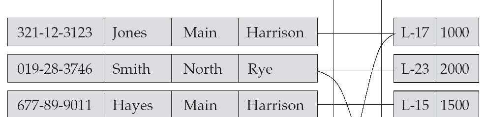
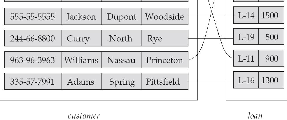
22 Entity Sets customer and loan 22 customer_id customer_ customer_ customer_ loan_ amount name street city number
23 Relationship, Relationship Set 23 name since dname ssn lot did budget Employees Works_In Departments Relationship: Association among two or more entities. E.g.,1. Attishoo works in Pharmacy department. 2. Hayes depositor A-102 customer entity relationship set account entity relationships can have their own attributes.
24 Relationship, Relationship Set 24 Relationship Set: Collection of similar relationships. An n-ary relationship set R relates n entity sets E 1... E n ; each relationship in R involves entities e 1 E 1,..., e n E n A relationship set is a mathematical relation among n 2 entities, each taken from entity sets {(e1, e2, en) e1 E1, e2 E2,, en En} where (e1, e2,, en) is a relationship Example: (Hayes, A-102) depositor
25 25 Relationship Set borrower

26 Relationship Set 26 An attribute can also be property of a relationship set. For instance, the depositor relationship set between entity sets customer and account may have the attribute access-date
27 Degree of a Relationship Set 27 Refers to number of entity sets that participate in a relationship set. Relationship sets that involve two entity sets are binary (or degree two). Generally, most relationship sets in a database system are binary. Relationship sets may involve more than two entity sets. Example: Suppose employees of a bank may have jobs (responsibilities) at multiple branches, with different jobs at different branches. Then there is a ternary relationship set between entity sets employee, job, and branch Relationships between more than two entity sets are rare. Most relationships are binary.
28 Relationship Set 28 name ssn lot did dname budget since supervisor Employees subordinate Departments Works_In Reports_To Same entity set can participate in different relationship sets, or in different roles in the same set.
29 Binary vs. Ternary Relationships 29 If each policy is owned by just 1 employee: Key constraint on Policies would mean policy can only cover 1 dependent! name ssn lot pname age Employees Bad design name ssn lot Employees Covers Dependents Policies policyid cost pname age Dependents Think through all the constraints in the 2nd diagram! Purchaser Better design Beneficiary Policies policyid cost
30 30 Binary vs. Ternary Relationships (Contd.) Previous example illustrated a case when two binary relationships were better than one ternary relationship. An example in the other direction: a ternary relation Contracts relates entity sets Parts, Departments and Suppliers, and has descriptive attribute qty. No combination of binary relationships is an adequate substitute.
31 31 Binary vs. Ternary Relationships (Contd.) qty Parts Contract Departments Suppliers VS. Parts needs Departments can-supply Suppliers deals-with S can-supply P, D needs P, and D deals-with S does not imply that D has agreed to buy P from S. How do we record qty?

32 32 The Entity - Relationship Diagram (ERD)
33 Attributes 33 An entity is represented by a set of attributes, that is descriptive properties possessed by all members of an entity set. Example: customer = (customer_id, customer_name, customer_street, customer_city ) loan = (loan_number, amount ) Domain the set of permitted values for each attribute Attribute types: Simple and composite attributes. Single-valued and multi-valued attributes Example: multivalued attribute: phone_numbers Derived attributes Can be computed from other attributes Example: age, given date_of_birth
34 34 Composite Attributes

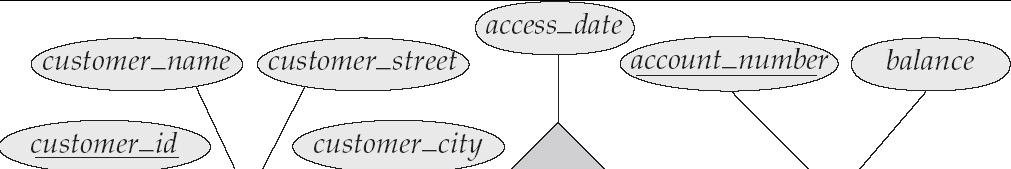
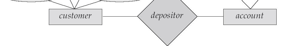
35 E-R Diagrams Rectangles represent entity sets. Diamonds represent relationship sets. Lines link attributes to entity sets and entity sets to relationship sets. Ellipses represent attributes Double ellipses represent multivalued attributes. Dashed ellipses denote derived attributes. Underline indicates primary key attributes


36 E-R Diagram With Composite, Multivalued, and Derived Attributes
37 Relationship Sets with Attributes
38 Mapping Cardinality Constraints 38 Express the number of entities to which another entity can be associated via a relationship set. Most useful in describing binary relationship sets. For a binary relationship set the mapping cardinality must be one of the following types: One to one One to many Many to one Many to many


39 Mapping Cardinalities 39 One to one One to many Note: Some elements in A and B may not be mapped to any elements in the other set

40 Mapping Cardinalities 40 Many to one Many to many Note: Some elements in A and B may not be mapped to any elements in the other set
41 Mapping Cardinalities 41 Relationship Types: One to One (represented in ERD as 1:1) One to Many (represented in ERD as 1:N) Many to One (represented in ERD as N:1) Many to Many (represented in ERD as M:N)
42 Relationship Types 42 One to One Company 1 1 director Employee One to Many Company 1 N director Employee Many to Many Company M director N Employee
43 Cardinality Constraints We express cardinality constraints by drawing either a directed line ( ), signifying one, or an undirected line ( ), signifying many, between the relationship set and the entity set. One-to-one relationship: A customer is associated with at most one loan via the relationship borrower A loan is associated with at most one customer via borrower
 loans via")
44 One-To-Many Relationship In the one-to-many relationship a loan is associated with at most one customer via borrower, a customer is associated with several (including 0) loans via borrower
 customers via borrower, a customer is associated with at most one loan via")
45 Many-To-One Relationships In a many-to-one relationship a loan is associated with several (including 0) customers via borrower, a customer is associated with at most one loan via borrower
 customers via borrower")
46 Many-To-Many Relationship A customer is associated with several (possibly 0) loans via borrower A loan is associated with several (possibly 0) customers via borrower

47 Alternative Notation for Cardinality Limits Cardinality limits can also express participation constraints
48 Keys 48 A super key of an entity set is a set of one or more attributes whose values uniquely determine each entity. A candidate key of an entity set is a minimal super key Customer_id is candidate key of customer account_number is candidate key of account Although several candidate keys may exist, one of the candidate keys is selected to be the primary key.
49 Keys for Relationship Set 49 The combination of primary keys of the participating entity sets forms a super key of a relationship set. (customer_id, account_number) is the super key of depositor NOTE: this means a pair of entity sets can have at most one relationship in a particular relationship set. Example: if we wish to track all access_dates to each account by each customer, we cannot assume a relationship for each access. We can use a multivalued attribute though Must consider the mapping cardinality of the relationship set when deciding what are the candidate keys Need to consider semantics of relationship set in selecting the primary key in case of more than one candidate key

50 Roles Entity sets of a relationship need not be distinct The labels manager and worker are called roles; they specify how employee entities interact via the works_for relationship set. Roles are indicated in E-R diagrams by labeling the lines that connect diamonds to rectangles. Role labels are optional, and are used to clarify semantics of the relationship

51 Participation of an Entity Set in a Relationship Set Total participation (indicated by double line): every entity in the entity set participates in at least one relationship in the relationship set E.g. participation of loan in borrower is total every loan must have a customer associated to it via borrower Partial participation: some entities may not participate in any relationship in the relationship set Example: participation of customer in borrower is partial
52 Participation Constraints 52 Does every employee work in a department? If so, this is a participation constraint the participation of Employees in Works_In is said to be total (vs. partial) What if every department has an employee working in it? Basically means at least one ssn name lot since did dname budget Employees Manages Departments Works_In since Means: exactly one

53 E-R Diagram with a Ternary Relationship
54 Cardinality Constraints on Ternary Relationship We allow at most one arrow out of a ternary (or greater degree) relationship to indicate a cardinality constraint E.g. an arrow from works_on to job indicates each employee works on at most one job at any branch. If there is more than one arrow, there are two ways of defining the meaning. E.g a ternary relationship R between A, B and C with arrows to B and C could mean 1. each A entity is associated with a unique entity from B and C or 2. each pair of entities from (A, B) is associated with a unique C entity, and each pair (A, C) is associated with a unique B Each alternative has been used in different formalisms To avoid confusion we outlaw more than one arrow
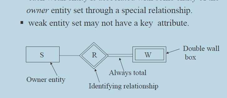
55 Weak Entities 55 A weak entity can be identified uniquely only by considering the primary key of another (owner) entity. Owner entity set and weak entity set must participate in a one-to-many relationship set (one owner, many weak entities). Weak entity set must have total participation in this identifying relationship set. name ssn lot cost pname age Employees Policy Dependents Weak entities have only a partial key (dashed underline)

56 56 Weak Entities

57 57 Weak Entities
58 Weak Entity Sets 58 An entity set that does not have a primary key is referred to as a weak entity set. The existence of a weak entity set depends on the existence of a identifying entity set it must relate to the identifying entity set via a total, one-tomany relationship set from the identifying to the weak entity set Identifying relationship depicted using a double diamond The discriminator (or partial key) of a weak entity set is the set of attributes that distinguishes among all the entities of a weak entity set. The primary key of a weak entity set is formed by the primary key of the strong entity set on which the weak entity set is existence dependent, plus the weak entity set s discriminator.

59 Weak Entity Sets (Cont.) 59 We depict a weak entity set by double rectangles. We underline the discriminator of a weak entity set with a dashed line. payment_number discriminator of the payment entity set Primary key for payment (loan_number, payment_number)
60 Weak Entity Sets (Cont.) 60 Note: the primary key of the strong entity set is not explicitly stored with the weak entity set, since it is implicit in the identifying relationship. If loan_number were explicitly stored, payment could be made a strong entity, but then the relationship between payment and loan would be duplicated by an implicit relationship defined by the attribute loan_number common to payment and loan
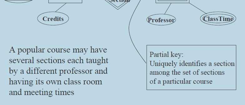
61 More Weak Entity Set Examples 61 In a university, a course is a strong entity and a course_offering can be modeled as a weak entity The discriminator of course_offering would be semester (including year) and section_number (if there is more than one section) If we model course_offering as a strong entity we would model course_number as an attribute. Then the relationship with course would be implicit in the course_number attribute
62 UNIT I (Part-2) 62 Database Design: Introduction to Database Design Entity - Relationship (E-R) Diagrams Additional Features of the E-R Model Conceptual design with the E-R Model Conceptual design for large enterprises
63 Additional or Extended E-R Features: Specialization 63 Top-down design process; we designate subgroupings within an entity set that are distinctive from other entities in the set. These subgroupings become lower-level entity sets that have attributes or participate in relationships that do not apply to the higher-level entity set. Depicted by a triangle component labeled ISA (E.g. customer is a person). Attribute inheritance a lower-level entity set inherits all the attributes and relationship participation of the higher-level entity set to which it is linked.
64 64 Specialization Example
65 Specialization Example
66 ISA (`is a ) Hierarchies ssn name lot 66 Employees hourly_wages hours_worked ISA contractid Hourly_Emps Contract_Emps As in C++, or other PLs, attributes are inherited. If we declare A ISA B, every A entity is also considered to be a B entity.
67 ISA (`is a ) Hierarchies 67 Overlap constraints: Can Simon be an Hourly_Emps as well as a Contract_Emps entity? (Allowed/disallowed) Covering constraints: Does every Employees entity also have to be an Hourly_Emps or a Contract_Emps entity? (Yes/no) Reasons for using ISA: To add descriptive attributes specific to a subclass. i.e. not appropriate for all entities in the superclass To identify entities that participate in a particular relationship i.e., not all superclass entities participate
68 Extended ER Features: Generalization 68 A bottom-up design process combine a number of entity sets that share the same features into a higher-level entity set. Specialization and generalization are simple inversions of each other; they are represented in an E-R diagram in the same way. The terms specialization and generalization are used interchangeably.
69 Specialization and Generalization (Cont.) 69 Can have multiple specializations of an entity set based on different features. E.g. permanent_employee vs. temporary_employee, in addition to officer vs. secretary vs. teller Each particular employee would be a member of one of permanent_employee or temporary_employee, and also a member of one of officer, secretary, or teller The ISA relationship also referred to as superclass - subclass relationship
70 70 Design Constraints on a Specialization/Generalization Constraint on which entities can be members of a given lowerlevel entity set. condition-defined Example: all customers over 65 years are members of senior-citizen entity set; senior-citizen ISA person. user-defined Constraint on whether or not entities may belong to more than one lower-level entity set within a single generalization.
71 71 Disjoint Design Constraints on a Specialization/Generalization an entity can belong to only one lower-level entity set Noted in E-R diagram by writing disjoint next to the ISA triangle Overlapping an entity can belong to more than one lower-level entity set
72 72 Design Constraints on a Specialization/Generalization (cont.) Completeness constraint -- specifies whether or not an entity in the higher-level entity set must belong to at least one of the lower-level entity sets within a generalization. total : an entity must belong to one of the lower-level entity sets partial: an entity need not belong to one of the lower-level entity sets
73 Aggregation 73 Consider the ternary relationship works_on, which we saw earlier Suppose we want to record managers for tasks performed by an employee at a branch
74 Aggregation ssn name lot 74 Used to model a relationship involving a relationship set. Allows us to treat a relationship set as an entity set for purposes of participation in (other) relationships. pid started_on Projects Employees Monitors pbudget since Sponsors did until dname Departments Aggregation vs. ternary relationship? Monitors is a distinct relationship, with a descriptive attribute. Also, can say that each sponsorship is monitored by at most one employee. budget
75 Aggregation (Cont.) 75 Relationship sets works_on and manages represent overlapping information Every manages relationship corresponds to a works_on relationship However, some works_on relationships may not correspond to any manages relationships So we can t discard the works_on relationship Eliminate this redundancy via aggregation Treat relationship as an abstract entity Allows relationships between relationships Abstraction of relationship into new entity Without introducing redundancy, the following diagram represents: An employee works on a particular job at a particular branch An employee, branch, job combination may have an associated manager
76 76 E-R Diagram With Aggregation
77 Aggregation 77 Consider the ternary relationship proj_guide Suppose we want to record evaluations of a student by a guide on a project
78 78 Aggregation
79 E-R Design Decisions 79 The use of an attribute or entity set to represent an object. Whether a real-world concept is best expressed by an entity set or a relationship set. The use of a ternary relationship versus a pair of binary relationships. The use of a strong or weak entity set. The use of specialization/generalization contributes to modularity in the design. The use of aggregation can treat the aggregate entity set as a single unit without concern for the details of its internal structure.


80 80 Complete Example for E - R Schema


81 81 Complete Example for E - R Schema


82 82 Complete Example for E - R Schema


83 83 Complete Example for E - R Schema
84 84 E-R Diagram for a Banking Enterprise
85 85 E-R Diagram for a University Enterprise
86 86 E-R Diagram for BANK MANAGEMENT SYSTEM

87 87 E-R Diagram for MOVIE DATABASE
88 88
89 89
90 90
91 91
92 92
93 93
94 94
95 95 Summary of Symbols Used in E-R Notation
96 96 Summary of Symbols (Cont.)
97 UNIT I (Part-2) 97 Database Design: Introduction to Database Design Entity - Relationship (E-R) Diagrams Additional Features of the E-R Model Conceptual design with the E-R Model Conceptual design for large enterprises
98 Conceptual Design Using the ER Model ER modeling can get tricky! Design choices: Should a concept be modeled as an entity or an attribute? Should a concept be modeled as an entity or a relationship? Identifying relationships: Binary or ternary? Aggregation? Note constraints of the ER Model: A lot of data semantics can (and should) be captured. But some constraints cannot be captured in ER diagrams. We ll refine things in our logical (relational) design
99 Entity vs. Attribute Should address be an attribute of Employees or an entity (related to Employees)? Depends upon how we want to use address information, and the semantics of the data: If we have several addresses per employee, address must be an entity (since attributes cannot be set-valued). If the structure (city, street, etc.) is important, address must be modeled as an entity (since attribute values are atomic). 99
100 Entity vs. Attribute (Cont.) 100 Works_In2 does not allow an employee to work in a department for two or more periods. Similar to the problem of wanting to record several addresses for an employee: we want to record several values of the descriptive attributes for each instance of this relationship. ssn name Employees ssn name lot Employees from lot from to Works_In2 Works_In3 Duration did did dname budget Departments to dname budget Departments
101 101 OK as long as a manager gets a separate discretionary budget (dbudget) for each dept. What if manager s dbudget covers all managed depts? (can repeat value, but such redundancy is problematic) Entity vs. Relationship name ssn Employees name ssn Employees since dbudget lot did Manages2 lot did dname budget Departments dname budget Departments is_manager managed_by since apptnum Mgr_Appts dbudget
102 Summary of Conceptual Design 102 Conceptual design follows requirements analysis, Yields a high-level description of data to be stored ER model popular for conceptual design Constructs are expressive, close to the way people think about their applications. Note: There are many variations on ER model Both graphically and conceptually Basic constructs: entities, relationships, and attributes (of entities and relationships). Some additional constructs: weak entities, ISA hierarchies, and aggregation.
103 UNIT I (Part-2) 103 Database Design: Introduction to Database Design Entity - Relationship (E-R) Diagrams Additional Features of the E-R Model Conceptual design with the E-R Model Conceptual design for large enterprises
104 Conceptual design for large enterprises 104 The process of conceptual design consists of more than just describing small fragments of the application in terms of ER diagrams. For a large enterprise, the design may require the efforts of more than one designer and span data and application code used by a number of user groups. An important aspect of the design process is the methodology used to structure the development of the overall design and to ensure that the design takes into account all user requirements and is consistent.
105 Conceptual design for large enterprises 105 The usual approach is that the requirements of various user groups are considered, any conflicting requirements are somehow resolved, and a single set of global requirements is generated at the end of the requirements analysis phase. An alternative approach is to develop separate conceptual schemas for different user groups and to then integrate these conceptual schemas. To integrate multiple conceptual schemas, we must establish correspondences between entities, relationships, and attributes, and we must resolve numerous kinds of conflicts.
106 END OF UNIT I (Part-2) 106 Database Design: Introduction to Database Design Entity - Relationship (E-R) Diagrams Additional Features of the E-R Model Conceptual design with the E-R Model Conceptual design for large enterprises
Chapter 6: Entity-Relationship Model
 Chapter 6: Entity-Relationship Model Database System Concepts, 5th Ed. See www.db-book.com for conditions on re-use Chapter 6: Entity-Relationship Model Design Process Modeling Constraints E-R Diagram
The Entity-Relationship Model
 The Entity-Relationship Model Chapter 2 Database Management Systems, R. Ramakrishnan and J. Gehrke 1 Overview of Database Design Conceptual design: (ER Model is used at this stage.) What are the entities
Chapter 6: Entity-Relationship Model
 Chapter 6: Entity-Relationship Model Database System Concepts, 5th Ed. See www.db-book.com for conditions on re-use Chapter 6: Entity-Relationship Model Design Process Modeling Constraints E-R Diagram
Database Systems. Lecture2:E-R model. Juan Huo( 霍娟 )
") Database Systems Lecture2:E-R model Juan Huo( 霍娟 ) Reference slides: http://www.cs.wisc.edu/ dbbook Berkeley, Professor Eben Haber,Professor Mary Roth Review: Benefits of a DBMS 1. Data independence applications
Database Systems Lecture2:E-R model Juan Huo( 霍娟 ) Reference slides: http://www.cs.wisc.edu/ dbbook Berkeley, Professor Eben Haber,Professor Mary Roth Review: Benefits of a DBMS 1. Data independence applications
The Entity-Relationship Model
 The Entity-Relationship Model Chapter 2 Database Management Systems 3ed, R. Ramakrishnan and J. Gehrke 1 Overview of Database Design Conceptual design: (ER Model is used at this stage.) What are the entities
Databases Model the Real World. The Entity- Relationship Model. Conceptual Design. Steps in Database Design. ER Model Basics. ER Model Basics (Contd.
 The Entity- Relationship Model CS 186 Fall 2002: Lecture 2 R &G - Chapter 2 A relationship, I think, is like a shark, you know? It has to constantly move forward or it dies. And I think what we got on
The Entity-Relationship Model. Overview of Database Design. ER Model Basics. (Ramakrishnan&Gehrke, Chapter 2)
") The Entity-Relationship Model (Ramakrishnan&Gehrke, Chapter 2) CS 432 Fall 2007 1 Overview of Database Design Conceptual design: (ER Model is used at this stage.) What are the entities and relationships
The Entity-Relationship Model (Ramakrishnan&Gehrke, Chapter 2) CS 432 Fall 2007 1 Overview of Database Design Conceptual design: (ER Model is used at this stage.) What are the entities and relationships
The Entity-Relationship (ER) Model
 Model") The Entity-Relationship (ER) Model (Study Cow book Chapter 2) Comp 521 Files and Databases Fall 2012 1 Overview of Database Design Conceptual design: (ER Model is used at this stage.) What are the entities
The Entity-Relationship (ER) Model (Study Cow book Chapter 2) Comp 521 Files and Databases Fall 2012 1 Overview of Database Design Conceptual design: (ER Model is used at this stage.) What are the entities
The Entity-Relationship Model. Overview of Database Design
 The Entity-Relationship Model Chapter 2, Chapter 3 (3.5 only) Database Management Systems 3ed, R. Ramakrishnan and J. Gehrke 1 Overview of Database Design Conceptual design: (ER Model is used at this stage.)
Introduction to Database Design. Dr. Kanda Runapongsa Dept of Computer Engineering Khon Kaen University
 Introduction to Database Design Dr. Kanda Runapongsa (krunapon@kku.ac.th) Dept of Computer Engineering Khon Kaen University Overview What are the steps in designing a database? Why is the ER model used
Contents. Database. Information Policy. C03. Entity Relationship Model WKU-IP-C03 Database / Entity Relationship Model
 Information Policy Database C03. Entity Relationship Model Code: 164323-03 Course: Information Policy Period: Spring 2013 Professor: Sync Sangwon Lee, Ph. D 1 Contents 01. Overview of Database Design 02.
Chapter 2: Entity-Relationship Model
 Chapter 2: Entity-Relationship Model! Entity Sets! Relationship Sets! Design Issues! Mapping Constraints! Keys! E-R Diagram! Extended E-R Features! Design of an E-R Database Schema! Reduction of an E-R
CIS 330: Web-driven Web Applications. Lecture 2: Introduction to ER Modeling
 CIS 330: Web-driven Web Applications Lecture 2: Introduction to ER Modeling 1 Goals of This Lecture Understand ER modeling 2 Last Lecture Why Store Data in a DBMS? Transactions (concurrent data access,
MIS Database Systems Entity-Relationship Model.
 MIS 335 - Database Systems Entity-Relationship Model http://www.mis.boun.edu.tr/durahim/ Ahmet Onur Durahim Learning Objectives Database Design Main concepts in the ER model? ER Diagrams Database Design
Databases Model the Real World. The Entity- Relationship Model. Conceptual Design. Steps in Database Design. ER Model Basics. ER Model Basics (Contd.
 The Entity- Relationship Model R &G - Chapter 2 A relationship, I think, is like a shark, you know? It has to constantly move forward or it dies. And I think what we got on our hands is a dead shark. Woody
Introduction to Database Design
 ICS 321 Fall 2009 Introduction to Database Design Asst. Prof. Lipyeow Lim Information & Computer Science Department University of Hawaii at Manoa 09/03/2009 Lipyeow Lim -- University of Hawaii at Manoa
Database Applications (15-415)
") Database Applications (15-415) The Entity Relationship Model Lecture 2, January 15, 2014 Mohammad Hammoud Today Last Session: Course overview and a brief introduction on databases and database systems
Database Applications (15-415) The Entity Relationship Model Lecture 2, January 15, 2014 Mohammad Hammoud Today Last Session: Course overview and a brief introduction on databases and database systems
Database Management Systems. Chapter 2 Part 2
 Database Management Systems Chapter 2 Part 2 Introduction to Database Design Database Management Systems 3ed, R. Ramakrishnan and J. Gehrke 1 Class Hierarchies Classify entities sets into Super-class and
CS/INFO 330 Entity-Relationship Modeling. Announcements. Goals of This Lecture. Mirek Riedewald
 CS/INFO 330 Entity-Relationship Modeling Mirek Riedewald mirek@cs.cornell.edu Announcements Office hour update (see class homepage) First homework assignment will be available from CMS later today Some
Chapter 6: Entity-Relationship Model
 Chapter 6: Entity-Relationship Model Database System Concepts, 5th Ed. See www.db-book.com for conditions on re-use Chapter 6: Entity-Relationship Model Design Process Modeling Constraints E-R Diagram
Design Process Modeling Constraints E-R Diagram Design Issues Weak Entity Sets Extended E-R Features Design of the Bank Database Reduction to
 Design Process Modeling Constraints E-R Diagram Design Issues Weak Entity Sets Extended E-R Features Design of the Bank Database Reduction to Relation Schemas Database Design UML A database can be modeled
6.1 RELATIONSHIP CONCEPTS
 1 SYLLABUS 6.1 Basic Entity Relationship Concepts: Entities, Relationship, Attributes 6.2 E R Diagram symbols 6.3 Conversion of Entity Relationship Model into Relations 6.4 Problems with Enitty Relationship
Example: specific person, company, event, plant
 A database can be modeled as: a collection of entities, relationship among entities. An entity is an object that exists and is distinguishable from other objects. Example: specific person, company, event,
COMP Instructor: Dimitris Papadias WWW page:
 COMP 5311 Instructor: Dimitris Papadias WWW page: http://www.cse.ust.hk/~dimitris/5311/5311.html Textbook Database System Concepts, A. Silberschatz, H. Korth, and S. Sudarshan. Reference Database Management
The Entity-Relationship (ER) Model 2
 Model 2") The Entity-Relationship (ER) Model 2 Week 2 Professor Jessica Lin Keys Differences between entities must be expressed in terms of attributes. A superkey is a set of one or more attributes which, taken
The Entity-Relationship (ER) Model 2 Week 2 Professor Jessica Lin Keys Differences between entities must be expressed in terms of attributes. A superkey is a set of one or more attributes which, taken
Overview of db design Requirement analysis Data to be stored Applications to be built Operations (most frequent) subject to performance requirement
 subject to performance requirement") ITCS 3160 Data Base Design and Implementation Jing Yang 2010 Fall Class 12: Data Modeling Using the Entity-Relationship (ER) Model Overview of db design Requirement analysis Data to be stored Applications
ITCS 3160 Data Base Design and Implementation Jing Yang 2010 Fall Class 12: Data Modeling Using the Entity-Relationship (ER) Model Overview of db design Requirement analysis Data to be stored Applications
Chapter 6: Entity-Relationship Model. The Next Step: Designing DB Schema. Identifying Entities and their Attributes. The E-R Model.
 Chapter 6: Entity-Relationship Model The Next Step: Designing DB Schema Our Story So Far: Relational Tables Databases are structured collections of organized data The Relational model is the most common
Database Applications (15-415)
") Database Applications (15-415) The Relational Model Lecture 3, January 18, 2015 Mohammad Hammoud Today Last Session: The entity relationship (ER) model Today s Session: ER model (Cont d): conceptual design
Database Applications (15-415) The Relational Model Lecture 3, January 18, 2015 Mohammad Hammoud Today Last Session: The entity relationship (ER) model Today s Session: ER model (Cont d): conceptual design
The Next Step: Designing DB Schema. Chapter 6: Entity-Relationship Model. The E-R Model. Identifying Entities and their Attributes.
 Chapter 6: Entity-Relationship Model Our Story So Far: Relational Tables Databases are structured collections of organized data The Relational model is the most common data organization model The Relational
Introduction to Data Management. Lecture #3 (Conceptual DB Design) Instructor: Chen Li
 Instructor: Chen Li") Introduction to Data Management Lecture #3 (Conceptual DB Design) Instructor: Chen Li 1 Announcements v HW #1 is now available v Today s plan Conceptual DB design, cont. Advanced ER concepts 2 Weak Entities
Introduction to Data Management Lecture #3 (Conceptual DB Design) Instructor: Chen Li 1 Announcements v HW #1 is now available v Today s plan Conceptual DB design, cont. Advanced ER concepts 2 Weak Entities
Chapter 6: Entity-Relationship Model. E-R Diagrams
 Chapter 6: Entity-Relationship Model A database can be modeled as: a collection of entities, relationship among entities. An entity is an object that exists and is distinguishable from other objects. Example:
OVERVIEW OF DATABASE DEVELOPMENT
 DATABASE SYSTEMS I WEEK 2: THE ENTITY-RELATIONSHIP MODEL OVERVIEW OF DATABASE DEVELOPMENT Requirements Analysis / Ideas High-Level Database Design Conceptual Database Design / Relational Database Schema
The Entity-Relationship Model. Steps in Database Design
 The Entity-Relationship Model Steps in Database Design 1) Requirement Analysis Identify the data that needs to be stored data requirements Identify the operations that need to be executed on the data functional
The Entity-Relationship Model
 The Entity-Relationship Model Chapter 2 Instructor: Vladimir Zadorozhny vladimir@sis.pitt.edu Information Science Program School of Information Sciences, University of Pittsburgh 1 Database: a Set of Relations
Lecture 14 of 42. E-R Diagrams, UML Notes: PS3 Notes, E-R Design. Thursday, 15 Feb 2007
 Lecture 14 of 42 E-R Diagrams, UML Notes: PS3 Notes, E-R Design Thursday, 15 February 2007 William H. Hsu Department of Computing and Information Sciences, KSU KSOL course page: http://snipurl.com/va60
CIS 330: Applied Database Systems
 1 CIS 330: Applied Database Systems Lecture 3: Introduction to ER Modeling The Relational Model Johannes Gehrke johannes@cs.cornell.edu http://www.cs.cornell.edu/johannes Announcements How many laptops
Data Modeling. Yanlei Diao UMass Amherst. Slides Courtesy of R. Ramakrishnan and J. Gehrke
 Data Modeling Yanlei Diao UMass Amherst Slides Courtesy of R. Ramakrishnan and J. Gehrke 1 Outline v Conceptual Design: ER Model v Relational Model v Logical Design: from ER to Relational 2 Conceptual
Chapter 7: Entity-Relationship Model
 Chapter 7: Entity-Relationship Model Database System Concepts, 6 th Ed. See www.db-book.com for conditions on re-use Chapter 7: Entity-Relationship Model Design Process Modeling Constraints E-R Diagram
Chapter 7: Entity-Relationship Model
 Chapter 7: Entity-Relationship Model Database System Concepts, 6 th Ed. See www.db-book.com for conditions on re-use Chapter 7: Entity-Relationship Model Design Process Modeling Constraints E-R Diagram
Chapter 2: Entity-Relationship Model. Entity Sets. Entity Sets customer and loan. Attributes. Relationship Sets. A database can be modeled as:
 Chapter 2: Entity-Relationship Model Entity Sets Entity Sets Relationship Sets Design Issues Mapping Constraints Keys E-R Diagram Extended E-R Features Design of an E-R Database Schema Reduction of an
Chapter 7: Entity-Relationship Model
 Chapter 7: Entity-Relationship Model Database System Concepts, 6 th Ed. See www.db-book.com for conditions on re-use Chapter 7: Entity-Relationship Model Design Process Modeling Constraints E-R Diagram
Modeling Your Data. Chapter 2. cs542 1
 Modeling Your Data Chapter 2 cs542 1 Part II Discussion of the Model: Good Design/ Bad Design cs542 2 Design : The Obvious Use meaningful and descriptive s (it s for the human after all) Keep as simple
Introduction to Database Design
 Introduction to Database Design UVic C SC 370 Daniel M German Introduction to Database Design (1.2.0) CSC 370 4/5/2005 14:52 p.1/33 Overview What are the steps in designing a database? What is the entity-relationship
Introduction to Data Management. Lecture #3 (Conceptual DB Design)
") Introduction to Data Management Lecture #3 (Conceptual DB Design) Instructor: Mike Carey mjcarey@ics.uci.edu Database Management Systems 3ed, R. Ramakrishnan and J. Gehrke 1 Announcements Today s plan:
Introduction to Data Management Lecture #3 (Conceptual DB Design) Instructor: Mike Carey mjcarey@ics.uci.edu Database Management Systems 3ed, R. Ramakrishnan and J. Gehrke 1 Announcements Today s plan:
The Relational Model. Chapter 3. Database Management Systems, R. Ramakrishnan and J. Gehrke 1
 The Relational Model Chapter 3 Database Management Systems, R. Ramakrishnan and J. Gehrke 1 Why Study the Relational Model? Most widely used model. Vendors: IBM, Informix, Microsoft, Oracle, Sybase, etc.
2. E-R Model. Entity Sets Relationship Sets Attributes
 3. E R Model 2. E-R Model Entity-Relationship Model Graphical Representation of Database Equivalent to Flow-Chart in Programming It makes easy to understand Database Prior Step to implement Actual Database
The Relational Model. Chapter 3
 The Relational Model Chapter 3 Why Study the Relational Model? Most widely used model. Systems: IBM DB2, Informix, Microsoft (Access and SQL Server), Oracle, Sybase, MySQL, etc. Legacy systems in older
CSIT5300: Advanced Database Systems
 CSIT5300: Advanced Database Systems L01: Entity Relationship (ER) Model Dr. Kenneth LEUNG Department of Computer Science and Engineering The Hong Kong University of Science and Technology Hong Kong SAR,
Database Design CENG 351
 Database Design Database Design Process Requirements analysis What data, what applica;ons, what most frequent opera;ons, Conceptual database design High level descrip;on of the data and the constraint
Introduction to Data Management. Lecture #3 (Conceptual DB Design)
") Introduction to Data Management Lecture #3 (Conceptual DB Design) Instructor: Mike Carey mjcarey@ics.uci.edu Database Management Systems 3ed, R. Ramakrishnan and J. Gehrke 1 Announcements Reminders: Sign
Introduction to Data Management Lecture #3 (Conceptual DB Design) Instructor: Mike Carey mjcarey@ics.uci.edu Database Management Systems 3ed, R. Ramakrishnan and J. Gehrke 1 Announcements Reminders: Sign
Introduction to Database Design
 Introduction to Database Design UVic C SC 370, Fall 2002 Daniel M. German Department of Computer Science University of Victoria 2 1 Introduction to Database Design CSC 370 dmgerman@uvic.ca Overview What
Entity-Relationship Diagrams
 Entity-Relationship Diagrams Fall 2017, Lecture 3 There is nothing worse than a sharp image of a fuzzy concept. Ansel Adams 1 Recall: Relational Database Management Relational DataBase Management Systems
Database Management Systems. Chapter 3 Part 2
 Database Management Systems Chapter 3 Part 2 The Relational Model Database Management Systems 3ed, R. Ramakrishnan and J. Gehrke 1 Logical DB Design: ER to Relational Entity sets to tables: CREATE TABLE
High Level Database Models
 ICS 321 Fall 2011 High Level Database Models Asst. Prof. Lipyeow Lim Information & Computer Science Department University of Hawaii at Manoa 9/21/2011 Lipyeow Lim -- University of Hawaii at Manoa 1 Database
ER Model Overview. The Entity-Relationship Model. Database Design Process. ER Model Basics
 ER Model Overview The Entity-Relationship Model Davood Rafiei Developed by Peter Chen in the mid 70 s Used for the design of conceptual schema. The world is described in terms of entities relationships
Database Applications (15-415)
") Database Applications (15-415) The Entity Relationship Model Lecture 2, January 12, 2016 Mohammad Hammoud Today Last Session: Course overview and a brief introduction on databases and database systems
Database Applications (15-415) The Entity Relationship Model Lecture 2, January 12, 2016 Mohammad Hammoud Today Last Session: Course overview and a brief introduction on databases and database systems
Introduction to Data Management. Lecture #3 (E-R Design, Cont d.)
") Introduction to Data Management Lecture #3 (E-R Design, Cont d.) Instructor: Mike Carey mjcarey@ics.uci.edu Database Management Systems 3ed, R. Ramakrishnan and J. Gehrke 1 Announcements Reminders: Sign
Introduction to Data Management Lecture #3 (E-R Design, Cont d.) Instructor: Mike Carey mjcarey@ics.uci.edu Database Management Systems 3ed, R. Ramakrishnan and J. Gehrke 1 Announcements Reminders: Sign
A database can be modeled as: + a collection of entities, + a set of relationships among entities.
 The Relational Model Lecture 2 The Entity-Relationship Model and its Translation to the Relational Model Entity-Relationship (ER) Model + Entity Sets + Relationship Sets + Database Design Issues + Mapping
CIS 330: Applied Database Systems. ER to Relational Relational Algebra
 CIS 330: Applied Database Systems ER to Relational Relational Algebra 1 Logical DB Design: ER to Relational Entity sets to tables: ssn name Employees lot CREATE TABLE Employees (ssn CHAR(11), name CHAR(20),
Database Management Systems. Syllabus. Instructor: Vinnie Costa
 Database Management Systems Syllabus Instructor: Vinnie Costa vcosta@optonline.net CSC056-Z1 Database Management Systems Vinnie Costa Hofstra University 1 Course Description This course is designed to
Relational Model. Topics. Relational Model. Why Study the Relational Model? Linda Wu (CMPT )
") Topics Relational Model Linda Wu Relational model SQL language Integrity constraints ER to relational Views (CMPT 354 2004-2) Chapter 3 CMPT 354 2004-2 2 Why Study the Relational Model? Most widely used
Topics Relational Model Linda Wu Relational model SQL language Integrity constraints ER to relational Views (CMPT 354 2004-2) Chapter 3 CMPT 354 2004-2 2 Why Study the Relational Model? Most widely used
Why Study the Relational Model? The Relational Model. Relational Database: Definitions. The SQL Query Language. Relational Query Languages
 Why Study the Relational Model? The Relational Model Most widely used model. Vendors: IBM, Informix, Microsoft, Oracle, Sybase, etc. Legacy systems in older models E.G., IBM s IMS Recent competitor: object-oriented
Chapter 7: Entity-Relationship Model
 Chapter 7: Entity-Relationship Model, 7th Ed. See www.db-book.com for conditions on re-use Chapter 7: Entity-Relationship Model Design Process Modeling Constraints E-R Diagram Design Issues Weak Entity
The Relational Model 2. Week 3
 The Relational Model 2 Week 3 1 We have seen how to create a database schema, how do we create an actual database on our computers? professor(pid : string, name : string) course(pid : string, number :
Entity-Relationship Model
 Entity-Relationship Model Data Models High-level or conceptual data models provide concepts that are close to the way many users perceive data, whereas low-level or physical data models provide concepts
The Relational Model. Why Study the Relational Model? Relational Database: Definitions
 The Relational Model Database Management Systems, R. Ramakrishnan and J. Gehrke 1 Why Study the Relational Model? Most widely used model. Vendors: IBM, Microsoft, Oracle, Sybase, etc. Legacy systems in
CSCC43H: Introduction to Databases
 CSCC43H: Introduction to Databases Lecture 2 Wael Aboulsaadat Acknowledgment: these slides are partially based on Prof. Garcia-Molina & Prof. Ullman slides accompanying the course s textbook. CSCC43: Introduction
Introduction to Data Management. Lecture #4 (E-R à Relational Design)
") Introduction to Data Management Lecture #4 (E-R à Relational Design) Instructor: Mike Carey mjcarey@ics.uci.edu Database Management Systems 3ed, R. Ramakrishnan and J. Gehrke 1 Announcements v Reminders:
Introduction to Data Management Lecture #4 (E-R à Relational Design) Instructor: Mike Carey mjcarey@ics.uci.edu Database Management Systems 3ed, R. Ramakrishnan and J. Gehrke 1 Announcements v Reminders:
Introduction to Data Management. Lecture #4 E-R Model, Still Going
 Introduction to Data Management Lecture #4 E-R Model, Still Going Instructor: Mike Carey mjcarey@ics.uci.edu Database Management Systems 3ed, R. Ramakrishnan and J. Gehrke Today s Reminders Continue to
SYLLABUS ADMIN DATABASE SYSTEMS I WEEK 2 THE ENTITY-RELATIONSHIP MODEL. Assignment #2 changed. A2Q1 moved to A3Q1
 DATABASE SYSTEMS I WEEK 2 THE ENTITY-RELATIONSHIP MODEL Class Time and Location: Tue 14:30-16:20 AQ3005 Thu 14:30-15:20 AQ3003 Course Website: http://www.cs.sfu.ca/cc/354/rfrank/ Instructor: Richard Frank,
The Relational Model. Chapter 3. Comp 521 Files and Databases Fall
 The Relational Model Chapter 3 Comp 521 Files and Databases Fall 2014 1 Why the Relational Model? Most widely used model by industry. IBM, Informix, Microsoft, Oracle, Sybase, MySQL, Postgres, Sqlite,
Relational Databases BORROWED WITH MINOR ADAPTATION FROM PROF. CHRISTOS FALOUTSOS, CMU /615
 Relational Databases BORROWED WITH MINOR ADAPTATION FROM PROF. CHRISTOS FALOUTSOS, CMU 15-415/615 Roadmap 3 Introduction Integrity constraints (IC) Enforcing IC Querying Relational Data ER to tables Intro
Intro to DB CHAPTER 6
 Intro to DB CHAPTER 6 DATABASE DESIGN &THEER E-R MODEL Chapter 6. Entity Relationship Model Design Process Modeling Constraints E-R Diagram Design Issues Weak Entity Sets Extended E-R Features Design of
Roadmap of This Lecture. Weak Entity Sets Extended E-R Features Reduction to Relation Schemas Database Design UML*
 E-R Model (II) 1 Roadmap of This Lecture Weak Entity Sets Extended E-R Features Reduction to Relation Schemas Database Design UML* 2 Weak Entity Sets An entity set that does not have a primary key is referred
Entity-Relationship Modelling. Entities Attributes Relationships Mapping Cardinality Keys Reduction of an E-R Diagram to Tables
 Entity-Relationship Modelling Entities Attributes Relationships Mapping Cardinality Keys Reduction of an E-R Diagram to Tables 1 Entity Sets A enterprise can be modeled as a collection of: entities, and
Database Systems ( 資料庫系統 )
") Database Systems ( 資料庫系統 ) 9.28.2011 Lecture #3 1 Course Administration Please download HW #1 from course homepage It is due 10/12/2011. This lecture: R&G Chapter 3 Next week reading: R&G Chapter 41~ 4.1
Database Systems ( 資料庫系統 ) 9.28.2011 Lecture #3 1 Course Administration Please download HW #1 from course homepage It is due 10/12/2011. This lecture: R&G Chapter 3 Next week reading: R&G Chapter 41~ 4.1
Chapter 7: Entity-Relationship Model. Chapter 7: Entity-Relationship Model
 Chapter 7: Entity-Relationship Model Database System Concepts, 6 th Ed. See www.db-book.com for conditions on re-use Chapter 7: Entity-Relationship Model Design Process Modeling Constraints E-R Diagram
Overview of Database Design Process Example Database Application (COMPANY) ER Model Concepts
 ER Model Concepts") Chapter Outline Overview of Database Design Process Example Database Application (COMPANY) ER Model Concepts Entities and Attributes Entity Types, Value Sets, and Key Attributes Relationships and Relationship
Chapter Outline Overview of Database Design Process Example Database Application (COMPANY) ER Model Concepts Entities and Attributes Entity Types, Value Sets, and Key Attributes Relationships and Relationship
Database Design. ER Model. Overview. Introduction to Database Design. UVic C SC 370. Database design can be divided in six major steps:
 Database Design Database design can be divided in six major steps: Requirements analysis Conceptual Database design (mostly done using the ER model) Logical Database design Schema refinement Physical Database
Entity Relationship Data Model. Slides by: Shree Jaswal
 Entity Relationship Data Model Slides by: Shree Jaswal Topics: Conceptual Modeling of a database, The Entity-Relationship (ER) Model, Entity Types, Entity Sets, Attributes, and Keys, Relationship Types,
Database Systems. Course Administration
 Database Systems ( ) September 20, 2004 Lecture #2 By Hao-hua Chu ( ) 1 Course Administration Can everyone get the textbook? HW #1 is out on the course homepage It is due one week from today. Next week
Unit1: Introduction. Database System Concepts, 6 th Ed. Silberschatz, Korth and Sudarshan See for conditions on re-use
 Unit1: Introduction Database System Concepts, 6 th Ed. See www.db-book.com for conditions on re-use Outline Introduction to Database Management Systems, Purpose of Database Systems, Database-System Applications,
The Relational Model. Chapter 3. Comp 521 Files and Databases Fall
 The Relational Model Chapter 3 Comp 521 Files and Databases Fall 2012 1 Why Study the Relational Model? Most widely used model by industry. IBM, Informix, Microsoft, Oracle, Sybase, etc. It is simple,
The En'ty Rela'onship Model
 The En'ty Rela'onship Model Debapriyo Majumdar DBMS Fall 2016 Indian Statistical Institute Kolkata Slides re-used, with minor modification, from Silberschatz, Korth and Sudarshan www.db-book.com Outline
Overview. Introduction to Database Design. ER Model. Database Design
 Introduction to Database Design UVic C SC 370 Dr. Daniel M. German Department of Computer Science Overview What are the steps in designing a database? What is the entity-relationship (ER) model? How does
Database Applications (15-415)
") Database Applications (15-415) ER to Relational & Relational Algebra Lecture 4, January 20, 2015 Mohammad Hammoud Today Last Session: The relational model Today s Session: ER to relational Relational algebra
Database Applications (15-415) ER to Relational & Relational Algebra Lecture 4, January 20, 2015 Mohammad Hammoud Today Last Session: The relational model Today s Session: ER to relational Relational algebra
The Relational Model (ii)
") ICS 321 Fall 2009 The Relational Model (ii) Asst. Prof. Lipyeow Lim Information and Computer Science Department University of Hawaii at Manoa 1 Internet Book Store Example Isbn title author qty price year
ICS 321 Fall 2009 The Relational Model (ii) Asst. Prof. Lipyeow Lim Information and Computer Science Department University of Hawaii at Manoa 1 Internet Book Store Example Isbn title author qty price year
High-Level Database Models (ii)
") ICS 321 Spring 2011 High-Level Database Models (ii) Asst. Prof. Lipyeow Lim Information & Computer Science Department University of Hawaii at Manoa 1 Logical DB Design: ER to Relational Entity sets to
ICS 321 Spring 2011 High-Level Database Models (ii) Asst. Prof. Lipyeow Lim Information & Computer Science Department University of Hawaii at Manoa 1 Logical DB Design: ER to Relational Entity sets to
CSE 530A. ER Model. Washington University Fall 2013
 CSE 530A ER Model Washington University Fall 2013 Database Design Requirements Analysis Conceptual Database Design Creates an abstract model Logical Database Design Converts abstract model to concrete
The Relational Model. Outline. Why Study the Relational Model? Faloutsos SCS object-relational model
 The Relational Model CMU SCS 15-415 C. Faloutsos Lecture #3 R & G, Chap. 3 Outline Introduction Integrity constraints (IC) Enforcing IC Querying Relational Data ER to tables Intro to Views Destroying/altering
From ER to Relational Model. Book Chapter 3 (part 2 )
") From ER to Relational Model Book Chapter 3 (part 2 ) Logical DB Design: ER to Relational Translate Entity sets to tables: ssn name Employees lot CREATE TABLE Employees (ssn CHAR(11), name CHAR(20), lot
From ER to Relational Model Book Chapter 3 (part 2 ) Logical DB Design: ER to Relational Translate Entity sets to tables: ssn name Employees lot CREATE TABLE Employees (ssn CHAR(11), name CHAR(20), lot
The Relational Model. Roadmap. Relational Database: Definitions. Why Study the Relational Model? Relational database: a set of relations
 The Relational Model CMU SCS 15-415/615 C. Faloutsos A. Pavlo Lecture #3 R & G, Chap. 3 Roadmap Introduction Integrity constraints (IC) Enforcing IC Querying Relational Data ER to tables Intro to Views
Conceptual Design. The Entity-Relationship (ER) Model
 Model") Conceptual Design. The Entity-Relationship (ER) Model CS430/630 Lecture 12 Slides based on Database Management Systems 3 rd ed, Ramakrishnan and Gehrke Database Design Overview Conceptual design The Entity-Relationship
Conceptual Design. The Entity-Relationship (ER) Model CS430/630 Lecture 12 Slides based on Database Management Systems 3 rd ed, Ramakrishnan and Gehrke Database Design Overview Conceptual design The Entity-Relationship
DATABASE MANAGEMENT SYSTEMS
 www..com Code No: N0321/R07 Set No. 1 1. a) What is a Superkey? With an example, describe the difference between a candidate key and the primary key for a given relation? b) With an example, briefly describe
Chapter Outline. Note 1. Overview of Database Design Process Example Database Application (COMPANY) ER Model Concepts
 ER Model Concepts") Chapter Outline Overview of Database Design Process Example Database Application (COMPANY) ER Model Concepts Entities and Attributes Entity Types, Value Sets, and Key Attributes Relationships and Relationship
Chapter Outline Overview of Database Design Process Example Database Application (COMPANY) ER Model Concepts Entities and Attributes Entity Types, Value Sets, and Key Attributes Relationships and Relationship
CONCEPTUAL DESIGN: ER TO RELATIONAL TO SQL
 RELATIONAL MODEL TO Data Model CONCEPTUAL DESIGN: ER TO RELATIONAL TO How to represent Entity sets, Relationship sets, Attributes, Key and participation constraints, Subclasses, Weak entity sets...? 2
Unit I. By Prof.Sushila Aghav MIT
 Unit I By Prof.Sushila Aghav MIT Introduction The Need for Databases Data Models Relational Databases Database Design Storage Manager Query Processing Transaction Manager DBMS Applications DBMS contains
UNIT II A. ENTITY RELATIONSHIP MODEL
 UNIT II A. ENTITY RELATIONSHIP MODEL Agenda En0ty & En0ty Sets A6ributes Rela0onship & Rela0onship Sets Constraints Mapping Cardinali0es, Par0cipa0on Constraints, Keys E-R Diagrams & Design of Database
ER Model. CSC 343 Winter 2018 MICHAEL LIUT
 ER Model CSC 343 Winter 2018 MICHAEL LIUT (MICHAEL.LIUT@UTORONTO.CA) DEPARTMENT OF MATHEMATICAL AND COMPUTATIONAL SCIENCES UNIVERSITY OF TORONTO MISSISSAUGA Overview of Database Design Conceptual Designs
Introduction to Data Management. Lecture #5 (E-R Relational, Cont.)
") Introduction to Data Management Lecture #5 (E-R Relational, Cont.) Instructor: Mike Carey mjcarey@ics.uci.edu Database Management Systems 3ed, R. Ramakrishnan and J. Gehrke 1 Announcements v HW#1 is due
Introduction to Data Management Lecture #5 (E-R Relational, Cont.) Instructor: Mike Carey mjcarey@ics.uci.edu Database Management Systems 3ed, R. Ramakrishnan and J. Gehrke 1 Announcements v HW#1 is due