Logical Database Design. ICT285 Databases: Topic 06
|
|
|
- Dylan Park
- 6 years ago
- Views:
Transcription

1 Logical Database Design ICT285 Databases: Topic 06
2 1. What is Logical Database Design?
3 Why bother? Bad logical database design results in bad physical database design, and generally results in poor database performance. So, if it is your responsibility to design a database from scratch, be sure you take the necessary time and effort to get the logical database design right. Once the logical design is right, then you also need to take the time to get the physical design right. Both the logical and physical design must be right before you can expect to get good performance out of your database. If the logical design is not right before you begin the development of your application, it is too late after the application has been implemented to fix it. No amount of fast, expensive hardware can fix the poor performance caused by poor logical database design
4 What is logical database design? - (And how does it differ from conceptual database design?) - Recall from Topic 5:
5 So what then, is logical database design? - The aim of logical database design is to produce a global model of the enterprise s data requirements, in a particular data model but independent of any particular DBMS - Q. What advantages are there in separating the conceptual design from the logical design process?
6 The Relational Model? - For this lecture we will assume that we have decided to implement our design using the relational model. - We do this for several reasons, including: - The vast majority of new databases are implemented in DBMS based on the RM - You are relatively familiar with the RM. - However, the process through which we will work in this topic would be similar regardless of the target data model.
7 2. A Logical Database Design Methodology
8 Create a table for each entity - The objective of this step is to create a list of relations that can be implemented in a relational database - We must represent all the concepts of the E-R model (entities, attributes, cardinality, subclasses, etc) in relations (tables)
9 Converting Entities to Tables Converting Entities: - Create a table that includes all the attributes of the entity StudentNo Student DOB - The name of the entity becomes the name of the table FamName GivenNames - The key attribute(s) of the entity becomes the primary key of the table - If necessary, normalise the table further, normally to 3NF. (StudentNo, DOB, FamName, GivenNames) STUDENT (StudentNo, DOB, FamName, GivenNames) STUDENT (StudentNo, DOB, FamName, GivenNames)
10 Representing 1:M relationships - Represent each entity as a table - Include the primary key of the 1-side (parent) table as foreign key in the N- side (child) table - In a 1:M relationship involving a weak entity with a composite key, it may not be necessary to include the FK as it is already there Staff The entities: STAFF(StaffNo, Name, Position, ) PROPERTYFORRENT (PropertyNo, Address, Type, Rooms, ) Become the relations: Property For Rent STAFF (StaffNo, Name, Position, ) PROPERTYFORRENT (PropertyNo, Address, Type, Rooms,, StaffNo)
11 Creating table to represent a 1:M relationship - Representing 1:M relationships - It may be a good idea to create a third table to represent a 1:M relationship if: - There is a possibility that the business rules may change so that the relationship becomes M:N in the future - If the M side has optional participation this may result in a many side table with many nulls in the FK field (if, for example, a property might not be managed by a member of staff) - There are attributes that belong to the relationship, rather than to either entity
12 Example An example: In a library that maintains current loans information only Borrower borrows Book Copy Date Borrowed DateDue The following solution would work: BORROWER (Member#, Name ) BOOK COPY (Control#, Title, Member#, DateBorrowed, DateDue) But is it the most efficient solution?? Can you suggest a better solution?
13 Representing 1:1 Relationships 1:1 relationships Must decide where the FK will be placed Will depend largely on the nature of the relationship Mandatory on both sides of the relationship Mandatory on one side only of the relationship Optional on both sides of the relationship 1:1 Recursive Relationships
14 Mandatory on both sides of the relationship - In this case, we may be able to combine the entities into a single relation - In the example, IF each client must have one and only one address, then we would put the address attributes in the Client relation Client The entities: CLIENT(ClientNo, Name, Tel ) CLIENTADDRESS (Street, Suburb, City, ) Become the relation: CLIENT(ClientNo, Name, Tel, Street, Suburb, City ) Client Address
15 Mandatory on one side only of the relationship - In this case, we would put the FK value in the relation that has the optional participation - In this way, we remove the nulls that would result if we put the FK on the mandatory side Staff The entities: STAFF(StaffNo, Name, Position ) NEXT-OF-KIN (Name, Address, Telephone ) Become the relations: STAFF(StaffNo, Name, Position ) NEXT-OF-KIN (Name, Address, Telephone, StaffNo ) Next-of-Kin
16 Optional on both sides of the relationship - In this case, the positioning of the FK is arbitrary - As a rule of thumb, it would be placed on the side of the relationship where it would result in less nulls - In the example, we have chosen to put the FK in the CAR relation as the majority of cars are used by staff, but only a small number of staff will use a car Staff The entities: STAFF(StaffNo, Name, Position ) CAR (Registration, ) Become the relations: STAFF(StaffNo, Name, Position ) CAR (Registration, StaffNo, ) Car
17 One-to-one recursive relationships - For a 1:1 recursive relationship, follow the rules for participation for a 1:1 relationship - mandatory participation on both sides, represent the recursive relationship as a single relation with two copies of the primary key (one renamed). Staff Becomes the relation: Has partner STAFF (StaffNo, Name, Position, PartnerNo)
18 One-to-one (1:1) recursive relationships - For a 1:1 recursive relationship, follow the rules for participation for a 1:1 relationship. - mandatory participation on only one side, option to create a single relation with two copies of the primary key, or to create a new relation to represent the relationship. The new relation would only have two attributes, both copies of the primary key. As before, the copies of the primary keys act as foreign keys and have to be renamed to indicate the purpose of each in the relation - optional participation on both sides, again create a new relation as described above.
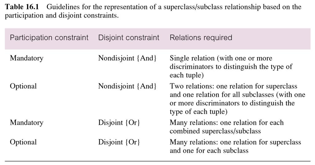
19 Representing subclasses in tables - There are various ways in which we can represent sub-classes - As for 1:1 relationships, the nature of the relationship will determine how we represent the entities as tables
20 Superclass:Subclass - Normally the key of the superclass and the key of the subclasses are the same - If it is appropriate for the subclass to have a different key, include the superclass key as a foreign key in the subclass table
21 suggested implementation
22 M:N Relationships - Replace with two 1:M relationships - This type of relationship cannot be represented as a M:N relationship in the relational model - Create a relation to represent the relationship and include any attributes that are part of the relationship Property For Rent The entities: Property For Rent Viewing Client PFR(PropertyNo, Address, Type ) CLIENT (ClientNo, Name, ) Become the relations: PFR(PropertyNo, Address, Type ) VIEWING (ClientNo,PropertyNo, Date, Comments) Client CLIENT (ClientNo, Name, )
23 Complex Relationships - A complex relationship is a relationship involving three or more entities Employee Customer Product - Should be resolved into n 1:M relationships and treated as per earlier discussion of 1:M relationships Employee Sale Customer Product
24 Multi-valued Attributes Student_ID - Any MVAs should be decomposed - A new entity and 1:M relationship should be created Student address address address Student Student address
25 Recursive Relationships - Decompose to identify an intermediate entity - If the relationship is M:N resolve as per other M:N relationships (e.g., person is related to many people) Supervised by Staff Staff Supervises Allocated_Staff Supervises
26 Relationships with Attributes - If there is a relationship with attributes in the conceptual model Student Studies Grade Unit - It should now be considered an entity Student Enrolment Grade Unit
27 Redundant Relationships - A relationship is redundant if the same information can be obtained via other relationships - Not ALL redundant relationships need to be removed, but it IS important to examine the meaning of all relationships Student Major School This relationship might be redundant
28 Validate model using normalisation - Recall from Topic 3 that normalisation is the process of grouping attributes together because there is a logical relationship between them - A normalised schema should be robust and avoid modification anomalies - 1NF: Removes repeating groups - 2NF: Removes partial functional dependencies - 3NF: Removes transitive functional dependencies - It is important at this stage to identify and review any relations that are part of our model that might not already in 3NF/BCNF.
29 Validate model against user transactions - If the final database is to be useful, it must support all of the transactions required by the users - The database itself and the application transactions are designed in parallel, and the database validated against the transactions at all stages - The ERD is amended if any problems are found
30 Validating the model against user transactions - Validating the ER model : - Can be done manually by tracing a path through the diagram - can the required entities be connected? - Validating the data model in this way can highlight problems (such as fan traps, or missing relationships) that mean the transaction can t be supported, or may reveal areas of the model that are never used by any transaction - An equivalent method is to look at the relations and give a detailed description of the operations required by the transaction - can the information be found? - Or try to formulate an SQL query that performs the operations required by the transaction
31 Examples: - How would you validate the following user transaction from the ERD on the next slide? - Produce a report listing the details of properties (including owner and responsible staff member) for rent at a given branch
32 Example Produce a report listing the details of properties for rent at a given branch Staff Property For Rent Branch Owner Q. Using a given branch, can we find the details of the property, staff and owner?
33 Define and check Integrity Constraints - Integrity refers to the validity and consistency of the stored data. - Integrity is expressed in terms of constraints, which are consistency rules that the database is not permitted to violate - In other words, in designing the database, we need to ensure that it correctly represents the system modelled, and remains consistent when data is added or deleted
34 Define and check Integrity Constraints - Recall the types of constraints from earlier topics - Required data - Domain constraints - Entity integrity - Referential integrity - Enterprise constraints/business rules - ALL CONSTRAINTS SHOULD BE DOCUMENTED AT THIS STAGE - we are not interested in whether the DBMS can support implementation of the constraints or not
35 Defining Constraints - Depending on the DBMS, constraints can be implemented: - Using data definition features of the DBMS - In SQL - In the application (through forms or in code) - As a general rule it is better to define a constraint with the database design - so it can be enforced consistently in every part of the application - However, often you can enforce more complex constraints, and have more flexibility in response, using forms or application code
36 Required data & attribute domain constraints - Required data some attributes must always hold a value ie they are not allowed to contain nulls. If so, this constraint must be documented. - Attribute domain constraints every attribute has a set of values that are legal. For example if the gender of a staff member can be only F or M. Then the domain of Gender is a single character string consisting of F or M. - What are enterprise constraints/business rules?
37 Entity integrity - The entity integrity constraint says that primary key values are unique and cannot be null. These are automatically enforced for a primary key you don t have to define them separately - Choosing a primary key - some principles: - Uniqueness must be guaranteed - Value is not likely to change - Domain should be big enough for expansion - Key names should be recognisable, eg. by using ID
38 Compound primary keys - So far we have used compound keys in weak entities (eg. OrderNo, ItemNo) or associative entities (RenterNo, PropertyNo) - However when you create the tables and define a primary key, you always have the choice of defining a separate, unique key instead surrogate key
39 Example - Suppose we have a holiday booking system. Clients can book many holidays in a year, and each holiday consists of several separate bookings at different places. - We could define tables as: - Client (ClientID, Name, Address) - OR - Holiday (ClientID, HolidayStartDate, ) - Booking (ClientID, HolidayStartDate, BookingDate, ) - Client (ClientID, Name, Address) - Holiday (HolidayID, ClientID, HolidayStartDate, ) - Booking (BookingID, HolidayID, BookingDate, ) Q. What are the pros and cons of each approach?
40 Natural vs Surrogate Key - There are arguments for both - Neither is necessarily the correct solution in ALL situations - It is important to note that all of the principles regarding candidate and primary keys still hold regardless
41 Referential integrity - The referential integrity constraint says that the value of a foreign key must reference an existing primary key, or be totally null - Referential integrity can be violated in a number of ways: - Inserting a new record with a foreign key that doesn't reference a primary key in another table - Solution: Disallow the insert
42 Violating RI - Referential integrity can also be violated by: - Deleting a record whose primary key is referenced by records in other tables - Solution: Disallow the delete - or Cascade the delete to delete all referencing records - or Set foreign keys to another, allowable value, then delete - Updating the primary key of a record that is referenced by records in other tables - Solution: Disallow the update - or Cascade the update to all foreign keys - change their values to match the primary key - or Set foreign keys to another, allowable value, then update
43 Choosing referential actions ( foreign key rules ) - The foreign key constraint clause specifies what should happen to the records containing the foreign key (the N-side or child table) if changes are made to the table with the primary key (the 1- side or parent table) - Inserts to the 1-side (parent) table: - Are no problem so long as the N-side is optional to the 1-side (so nothing needs to be specified in the constraint clause) - If the N-side is mandatory to the 1-side, must also add at least one record referencing it on the N-side - need to do this through the application - Updates to the primary key of the 1-side table: - Normally would cascade the update
44 Choosing referential actions ( foreign key rules ) - Deletes from the 1-side (parent) table: - If the N-side is from a weak entity or an associative entity (existence dependent) - cascade the delete - If the 1-side is mandatory to the N-side - disallow delete - or reassign N-side rows first then delete - If the 1-side is optional to the N-side - set foreign keys in N-side to null then delete - or reassign N-side rows first then delete
45 Review logical data model with user - At this stage the ERD should be complete and documented - Before moving on, the model and supporting documentation should be reviewed with the user
46 Merge local data models to create global model - If we have developed separate logical data models for different user views, they must be merged into a single global model - The activities in this step include: - Merge local logical data models into global model - Validate global logical data model - Review global logical data model with users.
47 Merge local logical data models into global model Tasks typically include: (1) Review the names and contents of entities/relations and their candidate keys. (2) Review the names and contents of relationships/foreign keys. (3) Merge entities/relations from the local data models (4) Include (without merging) entities/relations unique to each local data model (5) Merge relationships/foreign keys from the local data models. (6) Include (without merging) relationships/foreign keys unique to each local data model. (7) Check for missing entities/relations and relationships/foreign keys. (8) Check foreign keys. (9) Check Integrity Constraints. (10) Draw the global ER diagram (11) Update the documentation.
48 Check for future growth - Are there any foreseeable significant changes likely to happen? - If so, then our logical model needs to be able to accommodate these changes
49 Documenting the conceptual and logical database design process - The ERD and relational schema design needs to be supported by complete and consistent documentation - A data dictionary of all elements in the system should be maintained at all stages as the design is developed - this can be done by hand (eg. in a series of tables) or using a CASE tool
50 3. Documenting Logical Database Design
51 The Data Dictionary - The data dictionary should describe the following: - Entity types - entity name, description, aliases, likely number of occurrences based on how entity is used in the system - Attributes - attribute name, alias, owner entity, description, data type and size, required?, derived (and how computed)? domain (possible values), format, input mask ('picture') - Primary key and any alternate key - Relationships including cardinality and optionality - Relation schemas derived from ERD, including foreign keys and referential integrity constraints - Any additional constraints such as enterprise constraints that have not already been documented
52 CASE Tools - Useful tools in the Logical modelling stage - They can provide: - Diagramming - Data dictionary - Analysis of system consistency, syntax and completeness - Consistency between designers - Reverse engineering - Examples include VISIO, ERWin, Oracle Developer provides its own CASE tool - Remember: the tool is only as good as the person using it!
53 A short problem Dodgy Network Solutions (DNS) has a number of employees. DNS needs to store the following information about employees: Employee_ID (unique), Name, Address and Date of Birth. It also has several projects. DNS needs to store the following information about projects: Project_ID (unique), Project name, and start date. Each employee can be assigned to one, several, or no projects. A project must have at least one employee assigned to it, and may have many employees assigned. An employee s billing rate may vary by project, and DNS wishes to record the applicable billing rate for each employee when assigned to a particular project.
54 Dodgy Network Solutions (DNS) has a number of employees. DNS needs to store the following information about employees: Employee_ID (unique), Name, Address and Date of Birth. It also has several projects. DNS needs to store the following information about projects: Project_ID (unique), Project name, and start date. Each employee can be assigned to one, several, or no projects. A project must have at least one employee assigned to it, and may have many employees assigned. An employee s billing rate may vary by project, and DNS wishes to record the applicable billing rate for each employee when assigned to a particular project.
55 Dodgy Network Solutions (DNS) has a number of employees. DNS needs to store the following information about employees: Employee_ID (unique), Name, Address and Date of Birth. It also has several projects. DNS needs to store the following information about projects: Project_ID (unique), Project name, and start date. Each employee can be assigned to one, several, or no projects. A project must have at least one employee assigned to it, and may have many employees assigned. An employee s billing rate may vary by project, and DNS wishes to record the applicable billing rate for each employee when assigned to a particular project. EMPLOYEE
56 Dodgy Network Solutions (DNS) has a number of employees. DNS needs to store the following information about employees: Employee_ID (unique), Name, Address and Date of Birth. It also has several projects. DNS needs to store the following information about projects: Project_ID (unique), Project name, and start date. Each employee can be assigned to one, several, or no projects. A project must have at least one employee assigned to it, and may have many employees assigned. An employee s billing rate may vary by project, and DNS wishes to record the applicable billing rate for each employee when assigned to a particular project. EMPLOYEE PROJECT
57 Dodgy Network Solutions (DNS) has a number of employees. DNS needs to store the following information about employees: Employee_ID (unique), Name, Address and Date of Birth. It also has several projects. DNS needs to store the following information about projects: Project_ID (unique), Project name, and start date. Each employee can be assigned to one, several, or no projects. A project must have at least one employee assigned to it, and may have many employees assigned. An employee s billing rate may vary by project, and DNS wishes to record the applicable billing rate for each employee when assigned to a particular project. EMPLOYEE PROJECT
58 Dodgy Network Solutions (DNS) has a number of employees. DNS needs to store the following information about employees: Employee_ID (unique), Name, Address and Date of Birth. It also has several projects. DNS needs to store the following information about projects: Project_ID (unique), Project name, and start date. Each employee can be assigned to one, several, or no projects. A project must have at least one employee assigned to it, and may have many employees assigned. An employee s billing rate may vary by project, and DNS wishes to record the applicable billing rate for each employee when assigned to a particular project. EMPLOYEE 0< PROJECT
59 Dodgy Network Solutions (DNS) has a number of employees. DNS needs to store the following information about employees: Employee_ID (unique), Name, Address and Date of Birth. It also has several projects. DNS needs to store the following information about projects: Project_ID (unique), Project name, and start date. Each employee can be assigned to one, several, or no projects. A project must have at least one employee assigned to it, and may have many employees assigned. An employee s billing rate may vary by project, and DNS wishes to record the applicable billing rate for each employee when assigned to a particular project. EMPLOYEE 0< PROJECT
60 Dodgy Network Solutions (DNS) has a number of employees. DNS needs to store the following information about employees: Employee_ID (unique), Name, Address and Date of Birth. It also has several projects. DNS needs to store the following information about projects: Project_ID (unique), Project name, and start date. Each employee can be assigned to one, several, or no projects. A project must have at least one employee assigned to it, and may have many employees assigned. An employee s billing rate may vary by project, and DNS wishes to record the applicable billing rate for each employee when assigned to a particular project. EMPLOYEE > 0< PROJECT
61 Dodgy Network Solutions (DNS) has a number of employees. DNS needs to store the following information about employees: Employee_ID (unique), Name, Address and Date of Birth. It also has several projects. DNS needs to store the following information about projects: Project_ID (unique), Project name, and start date. Each employee can be assigned to one, several, or no projects. A project must have at least one employee assigned to it, and may have many employees assigned. An employee s billing rate may vary by project, and DNS wishes to record the applicable billing rate for each employee when assigned to a particular project. EMPLOYEE > 0< PROJECT
62 Dodgy Network Solutions (DNS) has a number of employees. DNS needs to store the following information about employees: Employee_ID (unique), Name, Address and Date of Birth. It also has several projects. DNS needs to store the following information about projects: Project_ID (unique), Project name, and start date. Each employee can be assigned to one, several, or no projects. A project must have at least one employee assigned to it, and may have many employees assigned. An employee s billing rate may vary by project, and DNS wishes to record the applicable billing rate for each employee when assigned to a particular project. EMPLOYEE > 0< PROJECT Billing Rate
63 Dodgy Network Solutions (DNS) has a number of employees. DNS needs to store the following information about employees: Employee_ID (unique), Name, Address and Date of Birth. It also has several projects. DNS needs to store the following information about projects: Project_ID (unique), Project name, and start date. Each employee can be assigned to one, several, or no projects. A project must have at least one employee assigned to it, and may have many employees assigned. An employee s billing rate may vary by project, and DNS wishes to record the applicable billing rate for each employee when assigned to a particular project. EMPLOYEE > EMPLOYEE PROJECT 0< PROJECT Billing Rate
64 Dodgy Network Solutions (DNS) has a number of employees. DNS needs to store the following information about employees: Employee_ID (unique), Name, Address and Date of Birth. It also has several projects. DNS needs to store the following information about projects: Project_ID (unique), Project name, and start date. Each employee can be assigned to one, several, or no projects. A project must have at least one employee assigned to it, and may have many employees assigned. An employee s billing rate may vary by project, and DNS wishes to record the applicable billing rate for each employee when assigned to a particular project. EMPLOYEE EMPLOYEE PROJECT > 0< PROJECT Billing Rate
65 Dodgy Network Solutions (DNS) has a number of employees. DNS needs to store the following information about employees: Employee_ID (unique), Name, Address and Date of Birth. It also has several projects. DNS needs to store the following information about projects: Project_ID (unique), Project name, and start date. Each employee can be assigned to one, several, or no projects. A project must have at least one employee assigned to it, and may have many employees assigned. An employee s billing rate may vary by project, and DNS wishes to record the applicable billing rate for each employee when assigned to a particular project. EMPLOYEE < EMPLOYEE PROJECT 0 > PROJECT Billing Rate
66 Dodgy Network Solutions (DNS) has a number of employees. DNS needs to store the following information about employees: Employee_ID (unique), Name, Address and Date of Birth. It also has several projects. DNS needs to store the following information about projects: Project_ID (unique), Project name, and start date. Each employee can be assigned to one, several, or no projects. A project must have at least one employee assigned to it, and may have many employees assigned. An employee s billing rate may vary by project, and DNS wishes to record the applicable billing rate for each employee when assigned to a particular project. EMPLOYEE < EMPLOYEE PROJECT 0 > PROJECT Billing Rate
67 Dodgy Network Solutions (DNS) has a number of employees. DNS needs to store the following information about employees: Employee_ID (unique), Name, Address and Date of Birth. It also has several projects. DNS needs to store the following information about projects: Project_ID (unique), Project name, and start date. Each employee can be assigned to one, several, or no projects. A project must have at least one employee assigned to it, and may have many employees assigned. An employee s billing rate may vary by project, and DNS wishes to record the applicable billing rate for each employee when assigned to a particular project. EMPLOYEE Employee_ID Name Address DateOfBirth < EMPLOYEE PROJECT 0 > Billing Rate PROJECT
68 Dodgy Network Solutions (DNS) has a number of employees. DNS needs to store the following information about employees: Employee_ID (unique), Name, Address and Date of Birth. It also has several projects. DNS needs to store the following information about projects: Project_ID (unique), Project name, and start date. Each employee can be assigned to one, several, or no projects. A project must have at least one employee assigned to it, and may have many employees assigned. An employee s billing rate may vary by project, and DNS wishes to record the applicable billing rate for each employee when assigned to a particular project. EMPLOYEE Employee_ID Name Address DateOfBirth < EMPLOYEE PROJECT 0 > Billing Rate PROJECT
69 Dodgy Network Solutions (DNS) has a number of employees. DNS needs to store the following information about employees: Employee_ID (unique), Name, Address and Date of Birth. It also has several projects. DNS needs to store the following information about projects: Project_ID (unique), Project name, and start date. Each employee can be assigned to one, several, or no projects. A project must have at least one employee assigned to it, and may have many employees assigned. An employee s billing rate may vary by project, and DNS wishes to record the applicable billing rate for each employee when assigned to a particular project. EMPLOYEE Employee_ID Name Address DateOfBirth < EMPLOYEE PROJECT 0 > Billing Rate PROJECT Project_ID Project_Name StartDate
70 Dodgy Network Solutions (DNS) has a number of employees. DNS needs to store the following information about employees: Employee_ID (unique), Name, Address and Date of Birth. It also has several projects. DNS needs to store the following information about projects: Project_ID (unique), Project name, and start date. Each employee can be assigned to one, several, or no projects. A project must have at least one employee assigned to it, and may have many employees assigned. An employee s billing rate may vary by project, and DNS wishes to record the applicable billing rate for each employee when assigned to a particular project. EMPLOYEE Employee_ID Name Address DateOfBirth < EMPLOYEE PROJECT 0 > Billing Rate PROJECT Project_ID Project_Name StartDate
71 Dodgy Network Solutions (DNS) has a number of employees. DNS needs to store the following information about employees: Employee_ID (unique), Name, Address and Date of Birth. It also has several projects. DNS needs to store the following information about projects: Project_ID (unique), Project name, and start date. Each employee can be assigned to one, several, or no projects. A project must have at least one employee assigned to it, and may have many employees assigned. An employee s billing rate may vary by project, and DNS wishes to record the applicable billing rate for each employee when assigned to a particular project. EMPLOYEE Employee_ID Name Address DateOfBirth < EMPLOYEE PROJECT 0 > Employee_ID Project_ID Billing_Rate PROJECT Project_ID Project_Name StartDate
72 Accident and Emergency Department Scenario Many hospitals have Accident and Emergency Departments (A&E Dept). These are either small casualty departments or major units handling ambulance cases. A hospital may have more than one A&E Dept though currently no hospital has more than four such department. Some hospitals do not have A&E departments. A hospital is sited in a District which may contain many hospitals. Each A&E Department may offer a number of A&E services such as outpatient clinics, minor surgery in an operating theatre associated with the department or a routine observation of patients in beds associated with the department. A patient may attend an A&E department or a particular service and they may attend several times for the same services. A senior NHS administrator has decided to carry out a survey of A&E departmental activity for one week. The administrator has prepared the form shown and as the quantity of data generated will be very large, wants a database designed to help handle and process the data. When records are transcribed from the paper form a unique patient number can be identified for each patient. Draw an ERD for this case Name DoB Doctor Name Date/Time Dept Hosp Dist Singh 12/05/1954 AX2W Jones 1/2/92, 1:00 SW12 H0123 Central (D2) Smith 5/08/1966 AX2W Jones 1/2/92, 1:35 SW12 H0123 Central (D2) Jenkins 5/08/1963 AQ1W Patel 1/2/92, 1:50 SW12 H0123 Central (D2) Singh 12/05/1954 AX2W Jones 3/2/92, 4:15 SW10 H0123 Central (D2) Smythe 12/05/1953 AQ1W Patel 3/2/92, 4:50 SW10 H0123 Central (D2)
73 Accident and Emergency Department Scenario Many hospitals have Accident and Emergency Departments (A&E Dept). These are either small casualty departments or major units handling ambulance cases. A hospital may have more than one A&E Dept though currently no hospital has more than four such department. Some hospitals do not have A&E departments. A hospital is sited in a District which may contain many hospitals. Each A&E Department may offer a number of A&E services such as outpatient clinics, minor surgery in an operating theatre associated with the department or a routine observation of patients in beds associated with the department. A patient may attend an A&E department or a particular service and they may attend several times for the same services. A senior NHS administrator has decided to carry out a survey of A&E departmental activity for one week. The administrator has prepared the form shown and as the quantity of data generated will be very large, wants a database designed to help handle and process the data. When records are transcribed from the paper form a unique patient number can be identified for each patient. Draw an ERD for this case
74 Accident and Emergency Department Scenario Many hospitals have Accident and Emergency Departments (A&E Dept). These are either small casualty departments or major units handling ambulance cases. A hospital may have more than one A&E Dept though currently no hospital has more than four such department. Some hospitals do not have A&E departments. A hospital is sited in a District which may contain many hospitals. Each A&E Department may offer a number of A&E services such as outpatient clinics, minor surgery in an operating theatre associated with the department or a routine observation of patients in beds associated with the department. A patient may attend an A&E department or a particular service and they may attend several times for the same services. A senior NHS administrator has decided to carry out a survey of A&E departmental activity for one week. The administrator has prepared the form shown and as the quantity of data generated will be very large, wants a database designed to help handle and process the data. When records are transcribed from the paper form a unique patient number can be identified for each patient. Draw an ERD for this case
75 Accident and Emergency Department Scenario Many hospitals have Accident and Emergency Departments (A&E Dept). These are either small casualty departments or major units handling ambulance cases. A hospital may have more than one A&E Dept though currently no hospital has more than four such department. Some hospitals do not have A&E departments. A hospital is sited in a District which may contain many hospitals. Each A&E Department may offer a number of A&E services such as outpatient clinics, minor surgery in an operating theatre associated with the department or a routine observation of patients in beds associated with the department. A patient may attend an A&E department or a particular service and they may attend several times for the same services. A senior NHS administrator has decided to carry out a survey of A&E departmental activity for one week. The administrator has prepared the form shown and as the quantity of data generated will be very large, wants a database designed to help handle and process the data. When records are transcribed from the paper form a unique patient number can be identified for each patient. PATIENT SERVICE DISTRICT HOSPITAL A&E DEPARTMENT
76 Accident and Emergency Department Scenario Many hospitals have Accident and Emergency Departments (A&E Dept). These are either small casualty departments or major units handling ambulance cases. A hospital may have more than one A&E Dept though currently no hospital has more than four such department. Some hospitals do not have A&E departments. A hospital is sited in a District which may contain many hospitals. Each A&E Department may offer a number of A&E services such as outpatient clinics, minor surgery in an operating theatre associated with the department or a routine observation of patients in beds associated with the department. A patient may attend an A&E department or a particular service and they may attend several times for the same services. A senior NHS administrator has decided to carry out a survey of A&E departmental activity for one week. The administrator has prepared the form shown and as the quantity of data generated will be very large, wants a database designed to help handle and process the data. When records are transcribed from the paper form a unique patient number can be identified for each patient. PATIENT SERVICE DISTRICT HOSPITAL A&E DEPARTMENT
77 Accident and Emergency Department Scenario Many hospitals have Accident and Emergency Departments (A&E Dept). These are either small casualty departments or major units handling ambulance cases. A hospital may have more than one A&E Dept though currently no hospital has more than four such department. Some hospitals do not have A&E departments. A hospital is sited in a District which may contain many hospitals. Each A&E Department may offer a number of A&E services such as outpatient clinics, minor surgery in an operating theatre associated with the department or a routine observation of patients in beds associated with the department. A patient may attend an A&E department or a particular service and they may attend several times for the same services. A senior NHS administrator has decided to carry out a survey of A&E departmental activity for one week. The administrator has prepared the form shown and as the quantity of data generated will be very large, wants a database designed to help handle and process the data. When records are transcribed from the paper form a unique patient number can be identified for each patient. PATIENT > < SERVICE > DISTRICT 0< HOSPITAL 0< A&E DEPARTMENT
78 Accident and Emergency Department Scenario Many hospitals have Accident and Emergency Departments (A&E Dept). These are either small casualty departments or major units handling ambulance cases. A hospital may have more than one A&E Dept though currently no hospital has more than four such department. Some hospitals do not have A&E departments. A hospital is sited in a District which may contain many hospitals. Each A&E Department may offer a number of A&E services such as outpatient clinics, minor surgery in an operating theatre associated with the department or a routine observation of patients in beds associated with the department. A patient may attend an A&E department or a particular service and they may attend several times for the same services. A senior NHS administrator has decided to carry out a survey of A&E departmental activity for one week. The administrator has prepared the form shown and as the quantity of data generated will be very large, wants a database designed to help handle and process the data. When records are transcribed from the paper form a unique patient number can be identified for each patient. PATIENT < >0 0 APPOINTMENT SERVICE > DISTRICT 0< HOSPITAL 0< A&E DEPARTMENT
79 Accident and Emergency Department Scenario Many hospitals have Accident and Emergency Departments (A&E Dept). These are either small casualty departments or major units handling ambulance cases. A hospital may have more than one A&E Dept though currently no hospital has more than four such department. Some hospitals do not have A&E departments. A hospital is sited in a District which may contain many hospitals. Each A&E Department may offer a number of A&E services such as outpatient clinics, minor surgery in an operating theatre associated with the department or a routine observation of patients in beds associated with the department. A patient may attend an A&E department or a particular service and they may attend several times for the same services. A senior NHS administrator has decided to carry out a survey of A&E departmental activity for one week. The administrator has prepared the form shown and as the quantity of data generated will be very large, wants a database designed to help handle and process the data. When records are transcribed from the paper form a unique patient number can be identified for each patient. PATIENT < >0 0 APPOINTMENT SERVICE > DISTRICT 0< HOSPITAL 0< A&E DEPARTMENT
80 Accident and Emergency Department Scenario Many hospitals have Accident and Emergency Departments (A&E Dept). These are either small casualty departments or major units handling ambulance cases. A hospital may have more than one A&E Dept though currently no hospital has more than four such department. Some hospitals do not have A&E departments. A hospital is sited in a District which may contain many hospitals. Each A&E Department may offer a number of A&E services such as outpatient clinics, minor surgery in an operating theatre associated with the department or a routine observation of patients in beds associated with the department. A patient may attend an A&E department or a particular service and they may attend several times for the same services. A senior NHS administrator has decided to carry out a survey of A&E departmental activity for one week. The administrator has prepared the form shown and as the quantity of data generated will be very large, wants a database designed to help handle and process the data. When records are transcribed from the paper form a unique patient number can be identified for each patient. PATIENT < APPOINTMENT SERVICE > 0 >0 DISTRICT 0< HOSPITAL 0< A&E DEPARTMENT Small Major
81 Accident and Emergency Department Scenario Many hospitals have Accident and Emergency Departments (A&E Dept). These are either small casualty departments or major units handling ambulance cases. A hospital may have more than one A&E Dept though currently no hospital has more than four such department. Some hospitals do not have A&E departments. A hospital is sited in a District which may contain many hospitals. Each A&E Department may offer a number of A&E services such as outpatient clinics, minor surgery in an operating theatre associated with the department or a routine observation of patients in beds associated with the department. A patient may attend an A&E department or a particular service and they may attend several times for the same services. A senior NHS administrator has decided to carry out a survey of A&E departmental activity for one week. The administrator has prepared the form shown and as the quantity of data generated will be very large, wants a database designed to help handle and process the data. When records are transcribed from the paper form a unique patient number can be identified for each patient. PATIENT < >0 0 APPOINTMENT SERVICE > DISTRICT 0< HOSPITAL 0< A&E DEPARTMENT Small X Z Major Y B
82 Accident and Emergency Department Scenario Many hospitals have Accident and Emergency Departments (A&E Dept). These are either small casualty departments or major units handling ambulance cases. A hospital may have more than one A&E Dept though currently no hospital has more than four such department. Some hospitals do not have A&E departments. A hospital is sited in a District which may contain many hospitals. Each A&E Department may offer a number of A&E services such as outpatient clinics, minor surgery in an operating theatre associated with the department or a routine observation of patients in beds associated with the department. A patient may attend an A&E department or a particular service and they may attend several times for the same services. 0< DOCTOR A senior NHS administrator has decided to carry out a survey of A&E departmental activity for one week. The administrator has prepared the form shown and as the quantity of data generated will be very large, wants a database designed to help handle and process the data. When records are transcribed from the paper form a unique patient number can be identified for each patient. 0< PATIENT < APPOINTMENT >0 0 SERVICE > DISTRICT 0< HOSPITAL 0< A&E DEPARTMENT Small X Z Major Y B
83 Accident and Emergency Department Scenario Many hospitals have Accident and Emergency Departments (A&E Dept). These are either small casualty departments or major units handling ambulance cases. A hospital may have more than one A&E Dept though currently no hospital has more than four such department. Some hospitals do not have A&E departments. A hospital is sited in a District which may contain many hospitals. Each A&E Department may offer a number of A&E services such as outpatient clinics, minor surgery in an operating theatre associated with the department or a routine observation of patients in beds associated with the department. A patient may attend an A&E department or a particular service and they may attend several times for the same services. 0< DOCTOR A senior NHS administrator has decided to carry out a survey of A&E departmental activity for one week. The administrator has prepared the form shown and as the quantity of data generated will be very large, wants a database designed to help handle and process the data. When records are transcribed from the paper form a unique patient number can be identified for each patient. 0< PATIENT < APPOINTMENT >0 0 SERVICE V DISTRICT 0< HOSPITAL 0< A&E DEPARTMENT Small X Z Major Y B
Chapter 17. Methodology Logical Database Design for the Relational Model
 Chapter 17 Methodology Logical Database Design for the Relational Model Chapter 17 - Objectives How to derive a set of relations from a conceptual data model. How to validate these relations using the
OBJECTIVES. How to derive a set of relations from a conceptual data model. How to validate these relations using the technique of normalization.
 7.5 逻辑数据库设计 OBJECTIVES How to derive a set of relations from a conceptual data model. How to validate these relations using the technique of normalization. 2 OBJECTIVES How to validate a logical data model
 0. Database Systems 1.1 Introduction to DBMS Information is one of the most valuable resources in this information age! How do we effectively and efficiently manage this information? - How does Wal-Mart
The DBMS accepts requests for data from the application program and instructs the operating system to transfer the appropriate data.
 Managing Data Data storage tool must provide the following features: Data definition (data structuring) Data entry (to add new data) Data editing (to change existing data) Querying (a means of extracting
3ISY402 DATABASE SYSTEMS
 3ISY402 DATABASE SYSTEMS - SQL: Data Definition 1 Leena Gulabivala Material from essential text: T CONNOLLY & C BEGG. Database Systems A Practical Approach to Design, Implementation and Management, 4th
THE COPPERBELT UNIVERSITY
 THE COPPERBELT UNIVERSITY SCHOOL OF INFORMATION AND COMMUNICATION TECHNOLOGY IT/IS DEPARTMENT MAY, 2018 SESSIONAL EXAMINATIONS CS235 DATABASE TECHNOLOGY TIME ALLOWED: THREE HOURS INSTRUCTIONS : Maximum
LECTURE 3: ENTITY-RELATIONSHIP MODELING
 LECTURE 3: ENTITY-RELATIONSHIP MODELING Ref. Chapter11 + Appendix F from Database Systems: A Practical Approach to Design, Implementation and Management. Thomas Connolly, Carolyn Begg. 1 IS220 : D a t
E-R Model. Hi! Here in this lecture we are going to discuss about the E-R Model.
 E-R Model Hi! Here in this lecture we are going to discuss about the E-R Model. What is Entity-Relationship Model? The entity-relationship model is useful because, as we will soon see, it facilitates communication
IS 263 Database Concepts
 IS 263 Database Concepts Lecture 1: Database Design Instructor: Henry Kalisti 1 Department of Computer Science and Engineering The Entity-Relationship Model? 2 Introduction to Data Modeling Semantic data
4. Entity Relationship Model
 4. Entity Relationship Model a) ER-Model: Used to construct conceptual data model, representing the structure and constraints of a database, which is not dependent on a software (like DBMS) or any data
Entity-Relationship Modelling. Entities Attributes Relationships Mapping Cardinality Keys Reduction of an E-R Diagram to Tables
 Entity-Relationship Modelling Entities Attributes Relationships Mapping Cardinality Keys Reduction of an E-R Diagram to Tables 1 Entity Sets A enterprise can be modeled as a collection of: entities, and
Database Principles: Fundamentals of Design, Implementation, and Management Tenth Edition. Chapter 7 Data Modeling with Entity Relationship Diagrams
 Database Principles: Fundamentals of Design, Implementation, and Management Tenth Edition Chapter 7 Data Modeling with Entity Relationship Diagrams Objectives In this chapter, students will learn: The
Objectives of logical design... Transforming the ERD diagram into relations. Relational database components. Mapping a composite attribute
 Logical database design and the relational model Objectives of logical design... Translate the conceptual design into a logical database design that can be implemented on a chosen DBMS Input: conceptual
Lecture4: Guidelines for good relational design Mapping ERD to Relation. Ref. Chapter3
 College of Computer and Information Sciences - Information Systems Dept. Lecture4: Guidelines for good relational design Mapping ERD to Relation. Ref. Chapter3 Prepared by L. Nouf Almujally & Aisha AlArfaj
Conceptual Database Design
 Conceptual Database Design Fall 2009 Yunmook Nah Department of Electronics and Computer Engineering Dankook University Conceptual Database Design Methodology Chapter 15, Connolly & Begg Steps to Build
Database Systems. Overview - important points. Lecture 5. Some introductory information ERD diagrams Normalization Other stuff 08/03/2015
 Lecture 5 Database Systems Instructor: M.Imran Khalil Imrankhalil3@gmail.com Resource:Imrankhalil3.wordpress.com University of Sargodha Canal Campus Lahore Overview - important points Some introductory
The Relational Model
 The Relational Model What is the Relational Model Relations Domain Constraints SQL Integrity Constraints Translating an ER diagram to the Relational Model and SQL Views A relational database consists
Lecture3: Data Modeling Using the Entity-Relationship Model.
 College of Computer and Information Sciences - Information Systems Dept. Lecture3: Data Modeling Using the Entity-Relationship Model. Ref. Chapter12 Prepared by L. Nouf Almujally & Aisha AlArfaj Rev. by
Conceptual Data Models for Database Design
 Conceptual Data Models for Database Design Entity Relationship (ER) Model The most popular high-level conceptual data model is the ER model. It is frequently used for the conceptual design of database
LECTURE 6: GUIDELINES FOR GOOD RELATIONAL DESIGN MAPPING ERD TO RELATIONS
 LECTURE 6: GUIDELINES FOR GOOD RELATIONAL DESIGN MAPPING ERD TO RELATIONS Ref. Chapter 16 Logical Database Design Methodology for the Relational Model 1 Objectives 2 How to derive a set of relations from
Data Modeling. Yanlei Diao UMass Amherst. Slides Courtesy of R. Ramakrishnan and J. Gehrke
 Data Modeling Yanlei Diao UMass Amherst Slides Courtesy of R. Ramakrishnan and J. Gehrke 1 Outline v Conceptual Design: ER Model v Relational Model v Logical Design: from ER to Relational 2 Conceptual
Detailed Data Modelling: Attribute Collection and Normalisation of Data
 Detailed Data Modelling IMS1002 /CSE1205 Systems Analysis and Design Detailed Data Modelling: Attribute Collection and Normalisation of Data The objective of detailed data modelling is to develop a detailed
Database Systems. A Practical Approach to Design, Implementation, and Management. Database Systems. Thomas Connolly Carolyn Begg
 Database Systems A Practical Approach to Design, Implementation, and Management For these Global Editions, the editorial team at Pearson has collaborated with educators across the world to address a wide
Relational Database Components
 Relational Database Components Chapter 2 Class 01: Relational Database Components 1 Class 01: Relational Database Components 2 Conceptual Database Design Components Class 01: Relational Database Components
IS 263 Database Concepts
 IS 263 Database Concepts Lecture 4: Normalization Instructor: Henry Kalisti 1 Department of Computer Science and Engineering Limitations of E- R Designs Provides a set of guidelines, does not result in
Objectives Definition iti of terms List five properties of relations State two properties of candidate keys Define first, second, and third normal for
 Chapter 5: Logical Database Design and the Relational Model Modern Database Management 9 th Edition Jeffrey A. Hoffer, Mary B. Prescott, Heikki Topi 2009 Pearson Education, Inc. Publishing as Prentice
Detailed Data Modelling. Detailed Data Modelling. Detailed Data Modelling. Identifying Attributes. Attributes
 IMS1002 /CSE1205 Systems Analysis and Design Detailed Data Modelling The objective of detailed data modelling is to develop a detailed data structure that: Detailed Data Modelling: Attribute Collection
1. Considering functional dependency, one in which removal from some attributes must affect dependency is called
 Q.1 Short Questions Marks 1. Considering functional dependency, one in which removal from some attributes must affect dependency is called 01 A. full functional dependency B. partial dependency C. prime
SUMMER EXAMINATIONS 2013
 SUMMER EXAMINATIONS 2013 CSY202913N MODULE TITLE Database Technology 1 LEVEL TIME ALLOWED Five Two Hours Instructions to students: Enter your student number not your name on all answer booklets. You are
COMP Instructor: Dimitris Papadias WWW page:
 COMP 5311 Instructor: Dimitris Papadias WWW page: http://www.cse.ust.hk/~dimitris/5311/5311.html Textbook Database System Concepts, A. Silberschatz, H. Korth, and S. Sudarshan. Reference Database Management
DATABASE MANAGEMENT SYSTEM
 DATABASE MANAGEMENT SYSTEM For COMPUTER SCIENCE DATABASE MANAGEMENT. SYSTEM SYLLABUS ER model. Relational model: relational algebra, tuple calculus, SQL. Integrity constraints, normal forms. File organization,
DATABASE DEVELOPMENT (H4)
") IMIS HIGHER DIPLOMA QUALIFICATIONS DATABASE DEVELOPMENT (H4) Friday 3 rd June 2016 10:00hrs 13:00hrs DURATION: 3 HOURS Candidates should answer ALL the questions in Part A and THREE of the five questions
IMIS HIGHER DIPLOMA QUALIFICATIONS DATABASE DEVELOPMENT (H4) Friday 3 rd June 2016 10:00hrs 13:00hrs DURATION: 3 HOURS Candidates should answer ALL the questions in Part A and THREE of the five questions
Chapter 1 SQL and Data
 Chapter 1 SQL and Data What is SQL? Structured Query Language An industry-standard language used to access & manipulate data stored in a relational database E. F. Codd, 1970 s IBM 2 What is Oracle? A relational
Chapter 2 ENTITY RELATIONSHIP MODEL
 INTRODUCTION Chapter 2 ENTITY RELATIONSHIP MODEL Data model is used to describe data, data relationship and constraints on data. A number of different data models have proposed. They can broadly be classified
The University of Nottingham
 The University of Nottingham SCHOOL OF COMPUTER SCIENCE AND INFORMATION TECHNOLOGY A LEVEL 1 MODULE, SPRING SEMESTER 2006-2007 DATABASE SYSTEMS Time allowed TWO hours Candidates must NOT start writing
Lecture 07. Spring 2018 Borough of Manhattan Community College
 Lecture 07 Spring 2018 Borough of Manhattan Community College 1 SQL Identifiers SQL identifiers are used to identify objects in the database, such as table names, view names, and columns. The ISO standard
Distributed Database Systems By Syed Bakhtawar Shah Abid Lecturer in Computer Science
 Distributed Database Systems By Syed Bakhtawar Shah Abid Lecturer in Computer Science 1 Distributed Database Systems Basic concepts and Definitions Data Collection of facts and figures concerning an object
Chapter 2: Entity-Relationship Model
 Chapter 2: Entity-Relationship Model! Entity Sets! Relationship Sets! Design Issues! Mapping Constraints! Keys! E-R Diagram! Extended E-R Features! Design of an E-R Database Schema! Reduction of an E-R
Lecture 03. Spring 2018 Borough of Manhattan Community College
 Lecture 03 Spring 2018 Borough of Manhattan Community College 1 2 Outline 1. Brief History of the Relational Model 2. Terminology 3. Integrity Constraints 4. Views 3 History of the Relational Model The
Entity Relationship Diagram (ERD) Dr. Moustafa Elazhary
 Dr. Moustafa Elazhary") Entity Relationship Diagram (ERD) Dr. Moustafa Elazhary Data Modeling Data modeling is a very vital as it is like creating a blueprint to build a house before the actual building takes place. It is built
Entity Relationship Diagram (ERD) Dr. Moustafa Elazhary Data Modeling Data modeling is a very vital as it is like creating a blueprint to build a house before the actual building takes place. It is built
Relational model continued. Understanding how to use the relational model. Summary of board example: with Copies as weak entity
 COS 597A: Principles of Database and Information Systems Relational model continued Understanding how to use the relational model 1 with as weak entity folded into folded into branches: (br_, librarian,
Database Technologies. Madalina CROITORU IUT Montpellier
 Database Technologies Madalina CROITORU croitoru@lirmm.fr IUT Montpellier Part 5 NORMAL FORMS AND NORMALISATION Database design In the database design one can follow a bottom up approach or a top down
namib I A U n IVERS I TY
 namib I A U n IVERS I TY OF SCIEnCE AnD TECH n 0 LOGY FACULTY OF COMPUTING AND INFORMATICS DEPARTMENT OF COMPUTER SCIENCE QUALIFICATION: BACHELOR OF COMPUTER SCIENCE QUALIFICATION CODE: 07BACS LEVEL: 5
Database Systems CSE Comprehensive Exam Spring 2005
 Database Systems CSE 5260 Spring 2005 Database Schema #1 Branch (Branch_Name, Branch_City, Assets) Customer (Customer_Name, SS#, Street, City, State, Zip_Code) Account (Account_Number, Branch_Name, Balance)
Database Logical Design
 Database Logical Design CIS 3730 Designing and Managing Data J.G. Zheng Fall 2010 1 Overview Relational model is a logical model Based on mathematical theories and rules Two ways to design a relational
Entity-Relationship Model &
 Entity-Relationship Model & IST 210 Diagram Todd S. Bacastow IST 210: Organization of data 2/1/2004 1 Design Principles Setting client has (possibly vague) idea of what he/she wants. YOUR task must design
Database Management Systems,
 Database Management Systems Database Design (2) 1 Topics Data Base Design Logical Design (Review) Physical Design Entity Relationship (ER) Model to Relational Model Entity Relationship Attributes Normalization
King Fahd University of Petroleum and Minerals
 Exam 1 March 16, 2008 Page 1 of 7 King Fahd University of Petroleum and Minerals Department of Information and Computer Science ICS 324: Database Systems Spring 2007-2008 Date: 16-March-2008 Major Exam
Full file at
 Modern Database Management, 10e (Hoffer/Ramesh/Topi) Chapter 2 Modeling Data in the Organization 1) Data modeling may be the most important part of the systems development process because: A) data characteristics
Represent entities and relations with diagrams
 LEARNING OBJECTIVES Define data modeling terms Describe E-R Model Identify entities and relations Represent entities and relations with diagrams WHAT IS DATA MODELING? A data model is a collection of concepts
Relational Model. Topics. Relational Model. Why Study the Relational Model? Linda Wu (CMPT )
") Topics Relational Model Linda Wu Relational model SQL language Integrity constraints ER to relational Views (CMPT 354 2004-2) Chapter 3 CMPT 354 2004-2 2 Why Study the Relational Model? Most widely used
Topics Relational Model Linda Wu Relational model SQL language Integrity constraints ER to relational Views (CMPT 354 2004-2) Chapter 3 CMPT 354 2004-2 2 Why Study the Relational Model? Most widely used
Fundamentals, Design, and Implementation, 9/e Copyright 2004 Database Processing: Fundamentals, Design, and Implementation, 9/e by David M.
 Chapter 5 Database Design Elements of Database Design Fundamentals, Design, and Implementation, 9/e Chapter 5/2 The Database Design Process Create tables and columns from entities and attributes Select
CS211 Lecture: Database Design
 CS211 Lecture: Database Design Objectives: last revised November 21, 2006 1. To introduce the anomalies that result from redundant storage of data 2. To introduce the notion of functional dependencies
Transforming ER to Relational Schema
 Transforming ER to Relational Schema Transformation of ER Diagrams to Relational Schema ER Diagrams Entities (Strong, Weak) Relationships Attributes (Multivalued, Derived,..) Generalization Relational
MIDTERM EXAMINATION Spring 2010 CS403- Database Management Systems (Session - 4) Ref No: Time: 60 min Marks: 38
 Ref No: Time: 60 min Marks: 38") Student Info StudentID: Center: ExamDate: MIDTERM EXAMINATION Spring 2010 CS403- Database Management Systems (Session - 4) Ref No: 1356458 Time: 60 min Marks: 38 BC080402322 OPKST 5/28/2010 12:00:00 AM
Student Info StudentID: Center: ExamDate: MIDTERM EXAMINATION Spring 2010 CS403- Database Management Systems (Session - 4) Ref No: 1356458 Time: 60 min Marks: 38 BC080402322 OPKST 5/28/2010 12:00:00 AM
A database can be modeled as: + a collection of entities, + a set of relationships among entities.
 The Relational Model Lecture 2 The Entity-Relationship Model and its Translation to the Relational Model Entity-Relationship (ER) Model + Entity Sets + Relationship Sets + Database Design Issues + Mapping
The Relational Model. Week 2
 The Relational Model Week 2 1 Relations A relation is a more concrete construction, of something we have seen before, the ER diagram. name S.S.N students street city A relation is (just!) a table! We will
A l Ain University Of Science and Technology
 A l Ain University Of Science and Technology 4 Handout(4) Database Management Principles and Applications The Entity Relationship (ER) Model http://alainauh.webs.com/ 1 In this chapter, you will learn:
Overview of db design Requirement analysis Data to be stored Applications to be built Operations (most frequent) subject to performance requirement
 subject to performance requirement") ITCS 3160 Data Base Design and Implementation Jing Yang 2010 Fall Class 12: Data Modeling Using the Entity-Relationship (ER) Model Overview of db design Requirement analysis Data to be stored Applications
ITCS 3160 Data Base Design and Implementation Jing Yang 2010 Fall Class 12: Data Modeling Using the Entity-Relationship (ER) Model Overview of db design Requirement analysis Data to be stored Applications
Conceptual Database Design. COSC 304 Introduction to Database Systems. Entity-Relationship Modeling. Entity-Relationship Modeling
 COSC 304 Introduction to Database Systems Entity-Relationship Modeling Dr. Ramon Lawrence University of British Columbia Okanagan ramon.lawrence@ubc.ca Conceptual Database Design Conceptual database design
The Relational Model. Chapter 3. Comp 521 Files and Databases Fall
 The Relational Model Chapter 3 Comp 521 Files and Databases Fall 2012 1 Why Study the Relational Model? Most widely used model by industry. IBM, Informix, Microsoft, Oracle, Sybase, etc. It is simple,
The Relational Model. Why Study the Relational Model? Relational Database: Definitions
 The Relational Model Database Management Systems, R. Ramakrishnan and J. Gehrke 1 Why Study the Relational Model? Most widely used model. Vendors: IBM, Microsoft, Oracle, Sybase, etc. Legacy systems in
ER-to-Relational Mapping
 Lecture 9 1 1. Context 2. The Algorithm Outline 2 Database Design and Implementation Process 3 Data Models 4 Example ERD 5 Resulting Relational Schema 6 Step 1: Regular Entity Types i. For each regular/strong
Relational Databases Overview
 Relational Databases Overview Full Description of the Relational Model Mapping ER diagrams to the Relational Model Integrity Constraints and the Relational Model Querying A Relational Database The Relational
Example 1 - Create Horizontal View. Example 2 - Create Vertical View. Views. Views
 Views Views RECALLS: View Dynamic result of one or more relational operations operating on the base relations to produce another relation. o Virtual relation that does not actually exist in the database
Advance Database Management System
 Advance Database Management System Conceptual Design Lecture- A simplified database design process Database Requirements UoD Requirements Collection and Analysis Functional Requirements A simplified database
Related download: Instructor Manual for Modern Database Management 12th Edition by Hoffer Venkataraman Topi (Case studies included)
") Modern Database Management Test Bank, 12e (Hoffer) Completed download: https://testbankarea.com/download/modern-database-management-12thedition-test-bank-hoffer-venkataraman-topi/ Related download: Instructor
Modern Database Management Test Bank, 12e (Hoffer) Completed download: https://testbankarea.com/download/modern-database-management-12thedition-test-bank-hoffer-venkataraman-topi/ Related download: Instructor
Step 2: Map ER Model to Tables
 Step 2: Map ER Model to Tables Asst. Prof. Dr. Kanda Runapongsa Saikaew (krunapon@kku.ac.th) Dept of Computer Engineering Khon Kaen University Overview How to map a set of tables from an ER model How to
Chapter 2: Entity-Relationship Model. Entity Sets. Entity Sets customer and loan. Attributes. Relationship Sets. A database can be modeled as:
 Chapter 2: Entity-Relationship Model Entity Sets Entity Sets Relationship Sets Design Issues Mapping Constraints Keys E-R Diagram Extended E-R Features Design of an E-R Database Schema Reduction of an
Database Design and Administration for OnBase WorkView Solutions. Mike Martel Senior Project Manager
 Database Design and Administration for OnBase WorkView Solutions Mike Martel Senior Project Manager 1. Solution Design vs. Database Design Agenda 2. Data Modeling/Design Concepts 3. ERD Diagramming Labs
The Entity-Relationship Model (ER Model) - Part 2
 - Part 2") Lecture 4 The Entity-Relationship Model (ER Model) - Part 2 By Michael Hahsler Based on slides for CS145 Introduction to Databases (Stanford) Lecture 4 > Section 2 What you will learn about in this section
Lecture 4 The Entity-Relationship Model (ER Model) - Part 2 By Michael Hahsler Based on slides for CS145 Introduction to Databases (Stanford) Lecture 4 > Section 2 What you will learn about in this section
1/24/2012. Chapter 7 Outline. Chapter 7 Outline (cont d.) CS 440: Database Management Systems
 CS 440: Database Management Systems") CS 440: Database Management Systems Chapter 7 Outline Using High-Level Conceptual Data Models for Database Design A Sample Database Application Entity Types, Entity Sets, Attributes, and Keys Relationship
CS 440: Database Management Systems Chapter 7 Outline Using High-Level Conceptual Data Models for Database Design A Sample Database Application Entity Types, Entity Sets, Attributes, and Keys Relationship
The Relational Model. Chapter 3. Comp 521 Files and Databases Fall
 The Relational Model Chapter 3 Comp 521 Files and Databases Fall 2014 1 Why the Relational Model? Most widely used model by industry. IBM, Informix, Microsoft, Oracle, Sybase, MySQL, Postgres, Sqlite,
Handout 6 Logical design: Translating ER diagrams into SQL CREATE statements
 06-13584 Fundamentals of Databases Spring Semester 2005 The University of Birmingham School of Computer Science Achim Jung February 16, 2005 Handout 6 Logical design: Translating ER diagrams into SQL CREATE
Database Applications (15-415)
") Database Applications (15-415) The Relational Model Lecture 3, January 18, 2015 Mohammad Hammoud Today Last Session: The entity relationship (ER) model Today s Session: ER model (Cont d): conceptual design
Database Applications (15-415) The Relational Model Lecture 3, January 18, 2015 Mohammad Hammoud Today Last Session: The entity relationship (ER) model Today s Session: ER model (Cont d): conceptual design
COSC 304 Introduction to Database Systems. Entity-Relationship Modeling
 COSC 304 Introduction to Database Systems Entity-Relationship Modeling Dr. Ramon Lawrence University of British Columbia Okanagan ramon.lawrence@ubc.ca Conceptual Database Design Conceptual database design
Comp 5311 Database Management Systems. 4b. Structured Query Language 3
 Comp 5311 Database Management Systems 4b. Structured Query Language 3 1 SQL as Data Definition Language Creates the Students relation. The type (domain) of each field is specified, and enforced by the
CS317 File and Database Systems
 CS317 File and Database Systems Lecture 9 Conceptual, Logical, and Physical DBMS Design http://dev.mysql.com/downloads/workbench October 22, 2017 Sam Siewert Reminders Assignment #4 Due Friday Assignment
Module 2 : Entity-Relationship Model 15
 Module 2 : Entity-Relationship Model 15 Module-02 Entity Relationship Data Model 2.1 Motivation Data modeling is an essential step in the process of creating any Database Application. It helps Database
ER Model. Objectives (2/2) Electricite Du Laos (EDL) Dr. Kanda Runapongsa Saikaew, Computer Engineering, KKU 1
 Electricite Du Laos (EDL) Dr. Kanda Runapongsa Saikaew, Computer Engineering, KKU 1") ER Model Asst. Prof. Dr. Kanda Runapongsa Saikaew (krunapon@kku.ac.th) Dept of Computer Engineering Khon Kaen University Objectives (1/2) Relational Data Model Terminology of relational data model How
ER Model Asst. Prof. Dr. Kanda Runapongsa Saikaew (krunapon@kku.ac.th) Dept of Computer Engineering Khon Kaen University Objectives (1/2) Relational Data Model Terminology of relational data model How
Chapter 12. Entity-Relationship Modeling
 Chapter 12 Entity-Relationship Modeling Chapter 12 - Objectives How to use Entity Relationship (ER) modeling in database design. Basic concepts associated with ER model. Diagrammatic technique for displaying
CMP-3440 Database Systems
 CMP-3440 Database Systems Database Architecture Lecture 02 zain 1 Database Design Process Application 1 Conceptual requirements Application 1 External Model Application 2 Application 3 Application 4 External
Relational Databases BORROWED WITH MINOR ADAPTATION FROM PROF. CHRISTOS FALOUTSOS, CMU /615
 Relational Databases BORROWED WITH MINOR ADAPTATION FROM PROF. CHRISTOS FALOUTSOS, CMU 15-415/615 Roadmap 3 Introduction Integrity constraints (IC) Enforcing IC Querying Relational Data ER to tables Intro
ER Modeling ER Diagram ID-Dependent and Weak Entities Pg 1
 ER Modeling ER Diagram ID-Dependent and Weak Entities Pg 1 ER Diagram ID-Dependent and Weak Entities Ray Lockwood Points: An ID-dependent entity is an entity whose identifier (key) includes the identifier
LAB 3 Notes. Codd proposed the relational model in 70 Main advantage of Relational Model : Simple representation (relationstables(row,
 LAB 3 Notes The Relational Model Chapter 3 In the previous lab we discussed the Conceptual Database Design Phase and the ER Diagram. Today we will mainly discuss how to convert an ER model into the Relational
Chapter 2 Conceptual Modeling. Objectives
 Chapter 2 Conceptual Modeling Basic Entity Relationship Diagrams 1 Objectives Definition of terms Importance of data modeling Write good names and definitions for entities, relationships, and attributes
Database Principles: Fundamentals of Design, Implementation, and Management Tenth Edition. Chapter 8 Data Modeling Advanced Concepts
 Database Principles: Fundamentals of Design, Implementation, and Management Tenth Edition Chapter 8 Data Modeling Advanced Concepts Objectives In this chapter, students will learn: About the extended entity
CMP-3440 Database Systems
 CMP-3440 Database Systems Logical Design Lecture 03 zain 1 Database Design Process Application 1 Conceptual requirements Application 1 External Model Application 2 Application 3 Application 4 External
2004 John Mylopoulos. The Entity-Relationship Model John Mylopoulos. The Entity-Relationship Model John Mylopoulos
 XVI. The Entity-Relationship Model The Entity Relationship Model The Entity-Relationship Model Entities, Relationships and Attributes Cardinalities, Identifiers and Generalization Documentation of E-R
The Relational Model. Chapter 3
 The Relational Model Chapter 3 Why Study the Relational Model? Most widely used model. Systems: IBM DB2, Informix, Microsoft (Access and SQL Server), Oracle, Sybase, MySQL, etc. Legacy systems in older
Chapter 6: Entity-Relationship Model. The Next Step: Designing DB Schema. Identifying Entities and their Attributes. The E-R Model.
 Chapter 6: Entity-Relationship Model The Next Step: Designing DB Schema Our Story So Far: Relational Tables Databases are structured collections of organized data The Relational model is the most common
The Relational Model. Chapter 3. Database Management Systems, R. Ramakrishnan and J. Gehrke 1
 The Relational Model Chapter 3 Database Management Systems, R. Ramakrishnan and J. Gehrke 1 Why Study the Relational Model? Most widely used model. Vendors: IBM, Informix, Microsoft, Oracle, Sybase, etc.
Lecture 03. Fall 2017 Borough of Manhattan Community College
 Lecture 03 Fall 2017 Borough of Manhattan Community College 1 2 Outline 1 Brief History of the Relational Model 2 Terminology 3 Integrity Constraints 4 Views 3 History of the Relational Model The Relational
The Relational Model. Roadmap. Relational Database: Definitions. Why Study the Relational Model? Relational database: a set of relations
 The Relational Model CMU SCS 15-415/615 C. Faloutsos A. Pavlo Lecture #3 R & G, Chap. 3 Roadmap Introduction Integrity constraints (IC) Enforcing IC Querying Relational Data ER to tables Intro to Views
A Flat file database. Problems with a flat file database (data redundancy)
") Data capture Before you can create a database, you need to collect data. This is known as data capture. One of the most common ways is to use and optical mark reader (OMR). An OMR sensor is used for marking
Data capture Before you can create a database, you need to collect data. This is known as data capture. One of the most common ways is to use and optical mark reader (OMR). An OMR sensor is used for marking
Entity Relationship Modeling
 Chapter 12 Entity Relationship Modeling Chapter Objectives In this chapter you will learn: How to use Entity Relationship (ER) modeling in database design. The basic concepts associated with the ER model:
DataBase Lab Lab # 7 ER Using ERWin
 In the name of Allah Islamic University of Gaza Faculty of Engineering Computer Engineering Department ECOM 4113 DataBase Lab Lab # 7 ER Using ERWin El-masry 2013 Objective To be familiar with Entity Relationship
Chapter 11 Database Concepts
 Chapter 11 Database Concepts INTRODUCTION Database is collection of interrelated data and database system is basically a computer based record keeping system. It contains the information about one particular
The Next Step: Designing DB Schema. Chapter 6: Entity-Relationship Model. The E-R Model. Identifying Entities and their Attributes.
 Chapter 6: Entity-Relationship Model Our Story So Far: Relational Tables Databases are structured collections of organized data The Relational model is the most common data organization model The Relational
Conceptual Database Design (ER modeling) Chapter Three
 Chapter Three") Conceptual Database Design (ER modeling) Chapter Three 1 Agenda (Chapter Three) Overview-database design Conceptual Design (E-R Modeling) Structural Constraints EER- Generalization and Specialization Reducing
Conceptual Database Design (ER modeling) Chapter Three 1 Agenda (Chapter Three) Overview-database design Conceptual Design (E-R Modeling) Structural Constraints EER- Generalization and Specialization Reducing