LECTURE 6: GUIDELINES FOR GOOD RELATIONAL DESIGN MAPPING ERD TO RELATIONS
|
|
|
- Frederick Shields
- 6 years ago
- Views:
Transcription


1 LECTURE 6: GUIDELINES FOR GOOD RELATIONAL DESIGN MAPPING ERD TO RELATIONS Ref. Chapter 16 Logical Database Design Methodology for the Relational Model 1
2 Objectives 2 How to derive a set of relations from a conceptual data model (Mapping ERD to Relations)
3 Derive relations for logical data model 3 In this step: We specify the name of the relation followed by a list of the relation s simple attributes enclosed in brackets. We then identify the primary key and foreign key(s) of the relation. Following the identification of a foreign key, the relation containing the referenced primary key is given Any derived attributes are also listed together with how each one is calculated For example: Staff (staffno, fname, lname, position, sex, DOB) Client (clientno, fname, lname, telno, preftype, maxrent, staffno) Foreign Key staffno references Staff(staffNo)
4 Derive relations for logical data model 4 The relationship that an entity has with another entity is represented by the primary key/foreign key mechanism. In deciding where to place the foreign key attribute(s), we must first identify the parent and child entities involved in the relationship. The parent entity refers to the entity that posts a copy of its primary key into the relation that represents the child entity, to act as the foreign key.
5 Derive relations for logical data model 5 We describe how relations are derived for the following structures that may occur in a conceptual data model: (1) strong entity types; (2) weak entity types; (3) composed / multi-valued / derived attributes; (4) binary relationship types; (5) recursive relationship types; (6) complex relationship types; (7) superclass/subclass relationship types;
6 Mapping Strong Entity types 6 For each strong entity in the data model, create a relation that includes all the simple attributes of that entity. If composite attributes exist, only their component simple attributes are needed. FName MName LName Name Employee EmpNo Employee ( EmpNo, FName, MName, LName ) Derived attributes are usually omitted.
7 Mapping Multi_valued Attributes 7 Create a new relation to represent multi-valued attribute and include primary key of the entity in the new relation, to act as a foreign key. The primary key of the new relation is the combination of the multi-valued attribute and the primary key of the entity. A multivalued attribute M of an entity E is represented by a separate table EM 1. Includes the multivalued attribute M in EM 2. Includes the PK of E as FK in EM 3. The PK of EM is the combination of the PK of E and the multivalued attribute M. EM ( M, EPK ) FK : EPK references E (EPK) E EPK M
8 Example of Multi-valued Attributes 8 BranchNo street city Branch telno postcode Branch( branchno, street, city, postcode) BranchTel (telno, branchno) FK: branchno references Branch(branchNo)
9 Example of Multi-valued Attributes 9 Branch BranchNo Street City PostCode telno B1 Brookline London B2 River drive Dubai B3 West river London Not allowed After Mapping: Branch BranchNo Street City PostCode B1 Brookline London 3310 B2 West End Glasgow 1320 B3 West River London 1100 Branch_Tel BranchNo telno B B B B
10 Mapping Weak Entities 10 Create a relation for each weak entity that includes all the simple attributes of that entity. A weak entity s key includes its key and the primary key of the owner entity as FK. The PK of the weak entity: is the combination of the two keys E1 M R N E2 B A Y X E1 ( A, B ) E2 (X, A, Y) FK : A references E1 (A)
11 Mapping Weak Entities - Example 11 1 M Employee has Dependents EmpNo Lname DepAge DepName Employee ( EmpNo, Lname) Dependents(EmpNo, DepName, DepAge) FK : EmpNo references Employee (EmpNo)
12 12 Mapping Binary Relationships One to many One to one Many to many
13 Mapping Binary Relationships 13 Identify one entity as parent and other entity as child As a general rule: PK of parent is added to child as FK Any attributes of the relationship are added to child relation
14 1. One-to-many (1:N) binary relationship 14 For each 1:* binary relationship, the entity on the one side of the relationship is designated as the parent entity and the entity on the many side is designated as the child entity To represent this relationship: Add a copy of the primary key attribute(s) of parent entity one side into the relation representing the child entity many side, to act as a foreign key. Add the attributes of the relationship into the relation. E1 1 N R E2 A E1-PK R1 B E2-PK E1 ( E1-PK, A) E2 ( E2-PK, B, E1_PK, R1 ) FK1 : E1-PK references E1 (E1-PK)
15 Example 1 15 The Department has Staff relationship is a 1:* relationship, A single department can has many staff members. Department is on the one side and represents the parent entity, and Staff is on the many side and represents the child entity. The relationship between these entities is established by placing a copy of the primary key of the Department (parent) entity, DeptNo, into the Staff (child) relation Department 1 N Has Staff DeptName DeptNo year sname scode Department (DeptNo, DeptName) Staff (scode, sname, DeptNo, year) FK: DeptNO references Department(DeptNo)
16 Example 1 Department DeptNo DeptName 140 Information System 160 Computer Science 171 Networks After Mapping: Department DeptNo DeptName 140 Information System 160 Computer Science 171 Networks Staff SID SName 1211 Nora 6550 Fatima 2250 Dena S Samar N Sara L Reem N. Staff SID SName DeptNo Year 1211 Nora Fatima Dena S Samar N Sara L Reem N
 Order")

17 Example 2 1 M CUSTOMER (Customer_ID, Customer_Name, Customer_Address) Order (Order_ID, Order_Date, Customer_ID) FK: Customer_ID references CUSTOMER (Customer_ID) Foreign key 17
18 2- One-to-one (1:1) binary relationship 18 Creating relations to represent a 1:1 relationship is slightly more complex as the cardinality cannot be used to help identify the parent and child entities in a relationship. The participation are used to help decide how to map the relationship. We consider how to create relations to represent the following participation constraints: (a) mandatory participation on both sides of 1:1 relationship (b) optional participation on both sides of 1:1 relationship (c) mandatory participation on one side of 1:1 relationship
19 2- One-to-one (1:1) binary relationship 19 A. Mandatory participation on both sides B. Optional on both sides Choose one entity and add its PK, and attributes of the relationship, to the other entity. E1 1 1 R E2 A E1-PK R1 B E2-PK E1 ( E1-PK, A) E2 ( E2-PK, B, E1-PK, R1 ) FK1 : E1-PK references E1 (E1-PK) E1 ( E1-PK, A, E2-PK, R1 ) FK1 : E2-PK references E2 (E2-PK) E2 ( E2-PK, B)
20 2- One-to-one (1:1) binary relationship 20 C. Mandatory participation on one side In this case we are able to identify the parent and child entities for the 1:1 relationship using the participation constraints. The entity that has optional participation in the relationship is designated as the parent entity, and the entity that has mandatory participation in the relationship is designated as the child entity To map this relation, Add the PK attributes of the optional side Parent, and attributes of the relationship, to the mandatory side Child. E1 1 1 R E2 A E1-PK R1 B E2-PK E1 ( E1-PK, A) E2 ( E2-PK, B, E1-PK, R1 ) FK1 : E1-PK references E1 (E1-PK)
21 1:1 relationship -Mandatory on both sides 24 Employee 1 1 has Office Emp_name Emp_id year officeno Office_Loc Employee( Emp_name, Emp_id ) Office (officeno, office_loc, Emp_id, year) FKs: Emp_id references Employee (Emp_id)
22 1:1 relationship - Mandatory on one sides 25 Employee 1 1 has Spouse Emp_name Emp_id year Spouse_id Spoude_name Employee( Emp_name, Emp_id ) Spouse(Spouse_id, Spouse_name, Emp_id, year) FKs: emp_id references employee (Emp_id)
23 1:1 relationship - Optional on both sides 26 Employee 1 1 use Car Emp_name Emp_id year Car_No Car_name Employee( Emp_name, Emp_id ) Car (Car_No, Car_name, Emp_id, year) FKs: Emp_id references Employee (Emp_id)
24 3. Many-to-many (M:N) binary relationship 27 Create a relation to represent the relationship and include any attributes that are part of the relationship. Add the primary key attribute(s) of the entities that participate in the relationship into the new relation, to act as foreign keys. These foreign keys will also form the primary key of the new relation, possibly in combination with some of the attributes of the relationship. E1 M R N E2 A E1-PK R1 B E2-PK E1 ( E1-PK, A) E2 ( E2-PK, B) R (E1-PK, E2-PK, R1 ) FK1 : E1-PK references E1 (E1-PK) FK2 : E2-PK references E2 (E2-PK)
25 Example 1 28 STUDENT M Enroll N SUBJECT stname stno date sname scode Student (stno, stname) Subject (scode, sname) Enroll (stno, scode, date) FKs: stno references Student(stNo) scode references Subject(sCode)
26 29 Student StNo StName Asma Nouf Noura Subject scode sname CS 110 Programming Language (1) IS 333 Project Management IS 220 Database Fundamentals Enroll SNO S_ID Date IS IS IS CS

27 Example 2 30 M M The Supplies relationship will need to become a separate relation
 31 QUOTE (Material_ID, Vendor_ID, Unit_price) FKs: Material_ID references RAW_MATERIALS (Material_ID) Vendor_ID references VENDOR")
28 Foreign key Composite primary key New relation Foreign key RAW_MATERIALS (Material_ID, Standard_cost, unit-of_measure) VENDOR (Vendor_ID, Vendor_Name, Vendor_Address) 31 QUOTE (Material_ID, Vendor_ID, Unit_price) FKs: Material_ID references RAW_MATERIALS (Material_ID) Vendor_ID references VENDOR (Vendor_ID)

29 32 Mapping Unary Relationships One to many One to one Many to many
30 Unary one-to-many (1:N) relationships 33 For a 1:N recursive relationship represent it as a single relation with two copies of the primary key ( one needs to be renamed and treated as the FK), plus attributes of the relationship.. A recursive foreign key is a foreign key in a relation that references the primary key values of that same relation. E1 1 M R A E1-PK R1 E1 ( E1-PK, A, E1_PK_Copy, R1 ) FK1 : E1_PK_Copy references E1 (E1-PK)
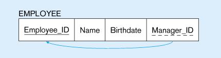

31 1 M Employee ( Employee_ID,Name,Birthdate,Manager_ID) FK : Manager_ID references Employee (Employee_ID) 34
32 Unary many-to-many (M:N) relationships 35 For a M:N recursive relationship, Two relations are created; One to represent the entity type in the relationship A new relation to represent the relationship. The new relation would includes two copies of the primary key, and attributes of the relationship. The copies of the primary keys act as foreign keys and have to be renamed to indicate the purpose of each in the relation. E1 ( E1-PK, A) M New_E ( E1-PK, E1_PK_copy, R1 ) FK1 : E1-PK references E1 (E1-PK) FK2 : E1_PK_copy references E1 (E1-PK) A E1 N E1-PK R R1

 FK2: Component_No references")
33 M M ITEM (Item_No, Name, Unit_Cost) COMPONENT (Item_No, Component_No, Quantity) FK1: Item_No references ITEM (Item_No) FK2: Component_No references ITEM (Item_No) 36
34 Unary one-to-one (1:1) 37 Mandatory participation on both sides Follow the rules of mapping 1:M unary relationship represent the recursive relationship as a single relation with two copies of the primary key. Optional on both sides Follow the rules of mapping M:N unary relationship create a new relation to represent the relationship. Mandatory on one side Follow either of the two methods above.
 FK1: Husband_SSN reference Person(SSN) FK2: Wife_SSN reference")
35 Unary one-to-one (1:1) 38 Person (SSN, Name) Marriage (Husband_SSN, Wife_SSN, Date) FK1: Husband_SSN reference Person(SSN) FK2: Wife_SSN reference Person(SSN)
36 39 Mapping Complex Relationships (n-ary)
37 Mapping Complex Relationships (n-ary) 40 For each complex n ary relationship R where n>2, create a new relation to represent the relationship and include any attributes that are part of the relationship. Add a copy of the primary key attribute(s) of the entities E1,E2.. En that participate in the complex relationship into the new relation, to act as foreign keys. However, this will change if the cardinality constraints on any of the participating entities in R is 1! Any foreign keys that represent a many relationship generally will form the primary key of this new relation, possibly in combination with some of the attributes of the relationship
38 Mapping Complex Relationships (n-ary) 41 A E3-PK E3 E1 R E2 A E1-PK R1 B E2-PK E1 ( E1-PK, A) E2 ( E2-PK, B) E3 ( E3-PK, A) R (E1-PK, E2-PK, E3-PK, R1 ) FK1 : E1-PK references E1 (E1-PK) FK2 : E2-PK references E2 (E2-PK) FK3: E3-PK references E3 (E3-PK)
39 Mapping Complex Relationships (n-ary) 42 Supplier (SName) Project (ProjName) Part (PartNo) Supply FKs : (SName, PartNo, ProjName, Quantity) SName references Supplier(SName) PartNo references Part(PartNo) ProjName references Project(ProjName)
40 43 Mapping Superclass/subclass relationship types
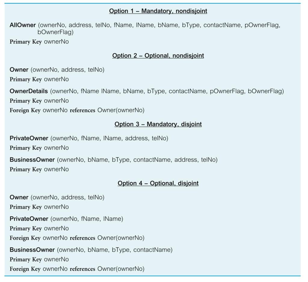
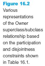
41 Mapping Superclass/subclass relationship types 44 Identify superclass entity as parent entity and subclass entity as the child entity. There are various options on how to represent such a relationship as one or more relations. The selection of the most appropriate option is dependent on a number of factors: Disjointness and participation constraints on the superclass/subclass relationship.

42 45 Mapping Superclass/subclass relationship types
43 Mapping Superclass/subclass relationship types 46 onwerno address telno Owner d fname bname lname name PrivateOwner BusinessOwner btype contactname How to map these entities?
44 47


45 48
46 Exercise 49 Convert the following ERD to relational tables, specify the primary key and foreign keys Fname Lname SSN Name Bdate sex Person Adress City Apt_no Street Rank Office d class Salary Faculty Student N Belong M M Major 1 Department
Lecture4: Guidelines for good relational design Mapping ERD to Relation. Ref. Chapter3
 College of Computer and Information Sciences - Information Systems Dept. Lecture4: Guidelines for good relational design Mapping ERD to Relation. Ref. Chapter3 Prepared by L. Nouf Almujally & Aisha AlArfaj
LECTURE 3: ENTITY-RELATIONSHIP MODELING
 LECTURE 3: ENTITY-RELATIONSHIP MODELING Ref. Chapter11 + Appendix F from Database Systems: A Practical Approach to Design, Implementation and Management. Thomas Connolly, Carolyn Begg. 1 IS220 : D a t
Lecture3: Data Modeling Using the Entity-Relationship Model.
 College of Computer and Information Sciences - Information Systems Dept. Lecture3: Data Modeling Using the Entity-Relationship Model. Ref. Chapter12 Prepared by L. Nouf Almujally & Aisha AlArfaj Rev. by
Chapter 17. Methodology Logical Database Design for the Relational Model
 Chapter 17 Methodology Logical Database Design for the Relational Model Chapter 17 - Objectives How to derive a set of relations from a conceptual data model. How to validate these relations using the
Objectives of logical design... Transforming the ERD diagram into relations. Relational database components. Mapping a composite attribute
 Logical database design and the relational model Objectives of logical design... Translate the conceptual design into a logical database design that can be implemented on a chosen DBMS Input: conceptual
Database Principles: Fundamentals of Design, Implementation, and Management Tenth Edition. Chapter 7 Data Modeling with Entity Relationship Diagrams
 Database Principles: Fundamentals of Design, Implementation, and Management Tenth Edition Chapter 7 Data Modeling with Entity Relationship Diagrams Objectives In this chapter, students will learn: The
Transforming ER to Relational Schema
 Transforming ER to Relational Schema Transformation of ER Diagrams to Relational Schema ER Diagrams Entities (Strong, Weak) Relationships Attributes (Multivalued, Derived,..) Generalization Relational
Elements of the E-R Model
 Chapter 3: The Entity Relationship Model Agenda Basic Concepts of the E-R model (Entities, Attributes, Relationships) Basic Notations of the E-R model ER Model 1 Elements of the E-R Model E-R model was
Ch 9: Mapping EER to Relational. Follow a seven-step algorithm to convert the basic ER model constructs into relations steps 1-7
 Ch 9: Mapping EER to Relational Follow a seven-step algorithm to convert the basic ER model constructs into relations steps 1-7 Additional steps for EER model for specialization/generalization steps 8a
MIT Database Management Systems Lesson 03: ER-to-Relational Mapping
 MIT 22033 Database Management Systems Lesson 03: ER-to-Relational Mapping By S. Sabraz Nawaz Senior Lecturer in MIT Department of Management and IT, SEUSL Chapter Outline ER-to-Relational Mapping Algorithm
Relational Model (cont d) & Entity Relational Model. Lecture 2
 & Entity Relational Model. Lecture 2") Relational Model (cont d) & Entity Relational Model Lecture 2 Relational Database Operators Relational algebra Defines theoretical way of manipulating table contents using relational operators: SELECT
Relational Model (cont d) & Entity Relational Model Lecture 2 Relational Database Operators Relational algebra Defines theoretical way of manipulating table contents using relational operators: SELECT
Conceptual Database Design
 Conceptual Database Design Fall 2009 Yunmook Nah Department of Electronics and Computer Engineering Dankook University Conceptual Database Design Methodology Chapter 15, Connolly & Begg Steps to Build
ER-to-Relational Mapping
 Lecture 9 1 1. Context 2. The Algorithm Outline 2 Database Design and Implementation Process 3 Data Models 4 Example ERD 5 Resulting Relational Schema 6 Step 1: Regular Entity Types i. For each regular/strong
Logical Database Design. ICT285 Databases: Topic 06
 Logical Database Design ICT285 Databases: Topic 06 1. What is Logical Database Design? Why bother? Bad logical database design results in bad physical database design, and generally results in poor database
Chapter 7 Relational Database Design by ER- and EERR-to-Relational Mapping
 Chapter 7 Relational Database Design by ER- and EERR-to-Relational Mapping Copyright 2004 Pearson Education, Inc. Chapter Outline ER-to-Relational Mapping Algorithm Step 1: Mapping of Regular Entity Types
Lecture 03. Spring 2018 Borough of Manhattan Community College
 Lecture 03 Spring 2018 Borough of Manhattan Community College 1 2 Outline 1. Brief History of the Relational Model 2. Terminology 3. Integrity Constraints 4. Views 3 History of the Relational Model The
Handout 4. Logical Database Modeling, Part 1: Relational Data Model. Transforming EER model to Relational.
 Handout 4 CS-605 Database Management and Modeling -Spring 18 Page 1 of 9 Handout 4 Logical Database Modeling, Part 1: Relational Data Model. Transforming EER model to Relational. Logical Database Design
Lecture 03. Fall 2017 Borough of Manhattan Community College
 Lecture 03 Fall 2017 Borough of Manhattan Community College 1 2 Outline 1 Brief History of the Relational Model 2 Terminology 3 Integrity Constraints 4 Views 3 History of the Relational Model The Relational
Lecture 10. Spring 2018 Borough of Manhattan Community College
 Lecture 10 Spring 2018 Borough of Manhattan Community College 1 Chapter Objectives In this lecture you will learn: The limitations of the basic concepts of the Entity-Relationship (ER) model and the requirements
More on the Chen Notation
 More on the Chen Notation Reference: http://www.vertabelo.com/blog/technical-articles/chen-erd-notation Peter Chen, who developed entity-relationship modeling and published his work in 1976, was one of
PES Institute of Technology Bangalore South Campus (1 K.M before Electronic City,Bangalore ) Department of MCA. Solution Set - Test-II
 Department of MCA. Solution Set - Test-II") PES Institute of Technology Bangalore South Campus (1 K.M before Electronic City,Bangalore 560100 ) Solution Set - Test-II Sub: Database Management Systems 16MCA23 Date: 04/04/2017 Sem & Section:II Duration:
PES Institute of Technology Bangalore South Campus (1 K.M before Electronic City,Bangalore 560100 ) Solution Set - Test-II Sub: Database Management Systems 16MCA23 Date: 04/04/2017 Sem & Section:II Duration:
Translation ER/EER to relational
 Database technology Lecture 4: Mapping of EER model to relations Jose M. Peña jose.m.pena@liu.se Translation ER/EER to relational Migrate from mini world model to a model understandable by a DBMS. 1 EER
Entity Relationship Data Model. Slides by: Shree Jaswal
 Entity Relationship Data Model Slides by: Shree Jaswal Topics: Conceptual Modeling of a database, The Entity-Relationship (ER) Model, Entity Types, Entity Sets, Attributes, and Keys, Relationship Types,
ER to Relational Mapping
 ER to Relational Mapping 1 / 19 ER to Relational Mapping Step 1: Strong Entities Step 2: Weak Entities Step 3: Binary 1:1 Relationships Step 4: Binary 1:N Relationships Step 5: Binary M:N Relationships
Entity Relationship Modeling. From Rob and Coronel (2004), Database Systems: Design, Implementation, and Management
, Database Systems: Design, Implementation, and Management") Entity Relationship Modeling Entity-Relationship Diagram (ERD) Components Entities: correspond to tables in the relational database Attributes: define the characteristics of entities Attributes have a
Entity Relationship Modeling Entity-Relationship Diagram (ERD) Components Entities: correspond to tables in the relational database Attributes: define the characteristics of entities Attributes have a
Database Systems ER Model. A.R. Hurson 323 CS Building
 ER Model A.R. Hurson 323 CS Building Database Design Data model is a group of concepts that helps to specify the structure of a database and a set of associated operations allowing data retrieval and data
Database Principles: Fundamentals of Design, Implementation, and Management Tenth Edition. Chapter 7 Data Modeling with Entity Relationship Diagrams
 Database Principles: Fundamentals of Design, Implementation, and Management Tenth Edition Chapter 7 Data Modeling with Entity Relationship Diagrams Objectives In this chapter, students will learn: The
OBJECTIVES. How to derive a set of relations from a conceptual data model. How to validate these relations using the technique of normalization.
 7.5 逻辑数据库设计 OBJECTIVES How to derive a set of relations from a conceptual data model. How to validate these relations using the technique of normalization. 2 OBJECTIVES How to validate a logical data model
CMP-3440 Database Systems
 CMP-3440 Database Systems Database Architecture Lecture 02 zain 1 Database Design Process Application 1 Conceptual requirements Application 1 External Model Application 2 Application 3 Application 4 External
Database Systems: Design, Implementation, and Management Tenth Edition. Chapter 4 Entity Relationship (ER) Modeling
 Modeling") Database Systems: Design, Implementation, and Management Tenth Edition Chapter 4 Entity Relationship (ER) Modeling 4.1 The Entity Relationship Model (ERM) ER model forms the basis of an ER diagram ERD
Database Systems: Design, Implementation, and Management Tenth Edition Chapter 4 Entity Relationship (ER) Modeling 4.1 The Entity Relationship Model (ERM) ER model forms the basis of an ER diagram ERD
Entity Relationship Modeling
 Chapter 12 Entity Relationship Modeling Chapter Objectives In this chapter you will learn: How to use Entity Relationship (ER) modeling in database design. The basic concepts associated with the ER model:
LELCTURE 4: ENHANCED ENTITY-RELATIONSHIP MODELING (EER)
") LELCTURE 4: ENHANCED ENTITY-RELATIONSHIP MODELING (EER) Ref. Chapter12 from Database Systems: A Practical Approach to Design, Implementation and Management. Thomas Connolly, Carolyn Begg. IS220 : D at
LELCTURE 4: ENHANCED ENTITY-RELATIONSHIP MODELING (EER) Ref. Chapter12 from Database Systems: A Practical Approach to Design, Implementation and Management. Thomas Connolly, Carolyn Begg. IS220 : D at
Database Systems: Design, Implementation, and Management Tenth Edition. Chapter 4 Entity Relationship (ER) Modeling
 Modeling") Database Systems: Design, Implementation, and Management Tenth Edition Chapter 4 Entity Relationship (ER) Modeling Objectives In this chapter, students will learn: The main characteristics of entity relationship
Database Systems: Design, Implementation, and Management Tenth Edition Chapter 4 Entity Relationship (ER) Modeling Objectives In this chapter, students will learn: The main characteristics of entity relationship
Translation of ER-diagram into Relational Schema. Dr. Sunnie S. Chung CIS430/530
 Translation of ER-diagram into Relational Schema Dr. Sunnie S. Chung CIS430/530 Learning Objectives Define each of the following database terms 9.2 Relation Primary key Foreign key Referential integrity
E-R Model. Hi! Here in this lecture we are going to discuss about the E-R Model.
 E-R Model Hi! Here in this lecture we are going to discuss about the E-R Model. What is Entity-Relationship Model? The entity-relationship model is useful because, as we will soon see, it facilitates communication
RELATIONAL DATA MODEL
 RELATIONAL DATA MODEL 3.1 Introduction The relational model of data was introduced by Codd (1970). It is based on a simple and uniform data structure - the relation - and has a solid theoretical and mathematical
Chapter 4. In this chapter, you will learn:
 Chapter Entity Relationship (ER) Modeling Database Systems: Design, Implementation, and Management, Seventh Edition, Rob and Coronel 1 In this chapter, you will learn: The main characteristics of entity
Advanced Databases (SE487) Prince Sultan University College of Computer and Information Sciences
 Prince Sultan University College of Computer and Information Sciences") Advanced Databases (SE487) Prince Sultan University College of Computer and Information Sciences ER to Relational Mapping Anis Koubaa Chapter 9 Outline } Relational Database Design Using ER-to-Relational
Advanced Databases (SE487) Prince Sultan University College of Computer and Information Sciences ER to Relational Mapping Anis Koubaa Chapter 9 Outline } Relational Database Design Using ER-to-Relational
Chapter 9: Relational DB Design byer/eer to Relational Mapping Relational Database Design Using ER-to- Relational Mapping Mapping EER Model
 Chapter 9: Relational DB Design byer/eer to Relational Mapping Relational Database Design Using ER-to- Relational Mapping Mapping EER Model Constructs to Relations Relational Database Design by ER- and
DATABASE SYSTEMS. Chapter 5 Entity Relationship (ER) Modelling DESIGN IMPLEMENTATION AND MANAGEMENT INTERNATIONAL EDITION ROB CORONEL CROCKETT
 Modelling DESIGN IMPLEMENTATION AND MANAGEMENT INTERNATIONAL EDITION ROB CORONEL CROCKETT") DATABASE SYSTEMS DESIGN IMPLEMENTATION AND MANAGEMENT INTERNATIONAL EDITION ROB CORONEL CROCKETT Chapter 5 Entity Relationship (ER) Modelling 1 Coronel & Crockett 978184480731) In this chapter, you will
DATABASE SYSTEMS DESIGN IMPLEMENTATION AND MANAGEMENT INTERNATIONAL EDITION ROB CORONEL CROCKETT Chapter 5 Entity Relationship (ER) Modelling 1 Coronel & Crockett 978184480731) In this chapter, you will
Database Logical Design
 Database Logical Design CIS 3730 Designing and Managing Data J.G. Zheng Fall 2010 1 Overview Relational model is a logical model Based on mathematical theories and rules Two ways to design a relational
Chapter 2 ENTITY RELATIONSHIP MODEL
 INTRODUCTION Chapter 2 ENTITY RELATIONSHIP MODEL Data model is used to describe data, data relationship and constraints on data. A number of different data models have proposed. They can broadly be classified
Objectives Definition iti of terms List five properties of relations State two properties of candidate keys Define first, second, and third normal for
 Chapter 5: Logical Database Design and the Relational Model Modern Database Management 9 th Edition Jeffrey A. Hoffer, Mary B. Prescott, Heikki Topi 2009 Pearson Education, Inc. Publishing as Prentice
Translation of ER-diagram into Relational Schema. Dr. Sunnie S. Chung CIS430/530
 Translation of ER-diagram into Relational Schema Dr. Sunnie S. Chung CIS430/530 Learning Objectives Define each of the following database terms 9.2 Relation Primary key Foreign key Referential integrity
Lecture7: SQL Overview, Oracle Data Type, DDL and Constraints Part #2
 IS220 : Database Fundamentals College of Computer and Information Sciences - Information Systems Dept. Lecture7: SQL Overview, Oracle Data Type, DDL and Constraints Part #2 Ref. Chapter6 Prepared by L.
Conceptual Database Design. COSC 304 Introduction to Database Systems. Entity-Relationship Modeling. Entity-Relationship Modeling
 COSC 304 Introduction to Database Systems Entity-Relationship Modeling Dr. Ramon Lawrence University of British Columbia Okanagan ramon.lawrence@ubc.ca Conceptual Database Design Conceptual database design
Database Logical Design
 Database Logical Design IT 5101 Introduction to Database Systems J.G. Zheng Fall 2011 Overview Relational model is a logical model Based on mathematical theories and rules Two ways to design a relational
CSIT5300: Advanced Database Systems
 CSIT5300: Advanced Database Systems L01: Entity Relationship (ER) Model Dr. Kenneth LEUNG Department of Computer Science and Engineering The Hong Kong University of Science and Technology Hong Kong SAR,
Relational DB Design by ER- and EER-to-Relational Mapping Design & Analysis of Database Systems
 Relational DB Design by ER- and EER-to-Relational Mapping 406.426 Design & Analysis of Database Systems Jonghun Park jonghun@snu.ac.kr Dept. of Industrial Engineering Seoul National University outline
Database Management Systems LECTURE NOTES 2
 Database Management Systems LECTURE NOTES 2 Relation: A table; Tuple: A row in a table; Attribute: A column in a table Degree: number of attributes; Cardinality: number of tuples Entity and Entity Sets:
COSC 304 Introduction to Database Systems. Entity-Relationship Modeling
 COSC 304 Introduction to Database Systems Entity-Relationship Modeling Dr. Ramon Lawrence University of British Columbia Okanagan ramon.lawrence@ubc.ca Conceptual Database Design Conceptual database design
CMP-3440 Database Systems
 CMP-3440 Database Systems Relational DB Languages SQL Lecture 06 zain 1 Purpose and Importance Database Language: To create the database and relation structures. To perform various operations. To handle
Outline. Note 1. CSIE30600 Database Systems ER/EER to Relational Mapping 2
 Outline ER-to-Relational Mapping Algorithm Step 1: Mapping of Regular Entity Types Step 2: Mapping of Weak Entity Types Step 3: Mapping of Binary 1:1 Relation Types Step 4: Mapping of Binary 1:N Relationship
4. Entity Relationship Model
 4. Entity Relationship Model a) ER-Model: Used to construct conceptual data model, representing the structure and constraints of a database, which is not dependent on a software (like DBMS) or any data
COMP102: Introduction to Databases, 13
 COMP102: Introduction to Databases, 13 Dr Muhammad Sulaiman Khan Department of Computer Science University of Liverpool U.K. 7 March, 2011 Logical Database Design: Enhanced ER Modeling Specific topics
Translation of ER-diagram into Relational Schema. Dr. Sunnie S. Chung CIS430/530
 Translation of ER-diagram into Relational Schema Dr. Sunnie S. Chung CIS430/530 Learning Objectives Define each of the following database terms Relation Primary key Foreign key Referential integrity Field
Chapter (4) Enhanced Entity-Relationship and Object Modeling
 Enhanced Entity-Relationship and Object Modeling") Chapter (4) Enhanced Entity-Relationship and Object Modeling Objectives Concepts of subclass and superclass and the related concepts of specialization and generalization. Concept of category, which is
Chapter (4) Enhanced Entity-Relationship and Object Modeling Objectives Concepts of subclass and superclass and the related concepts of specialization and generalization. Concept of category, which is
3ISY402 DATABASE SYSTEMS
 3ISY402 DATABASE SYSTEMS - SQL: Data Definition 1 Leena Gulabivala Material from essential text: T CONNOLLY & C BEGG. Database Systems A Practical Approach to Design, Implementation and Management, 4th
CS403- Database Management Systems Solved Objective Midterm Papers For Preparation of Midterm Exam
 CS403- Database Management Systems Solved Objective Midterm Papers For Preparation of Midterm Exam Question No: 1 ( Marks: 1 ) - Please choose one Which of the following is NOT a feature of Context DFD?
Non-overlappingoverlapping. Final outcome of the worked example On pages R&C pages R&C page 157 Fig 3.52
 Objectives Computer Science 202 Database Systems: Entity Relation Modelling To learn what a conceptual model is and what its purpose is. To learn the difference between internal models and external models.
Advance Database Management System
 Advance Database Management System Conceptual Design Lecture- A simplified database design process Database Requirements UoD Requirements Collection and Analysis Functional Requirements A simplified database
Database Management
 204320 - Database Management Chapter 9 Relational Database Design by ER and EERto-Relational Mapping Adapted for 204320 by Areerat Trongratsameethong Copyright 2011 Pearson Education, Inc. Publishing as
Chapter 4 Entity Relationship Modeling In this chapter, you will learn:
 Chapter Entity Relationship Modeling In this chapter, you will learn: What a conceptual model is and what its purpose is The difference between internal and external models How internal and external models
Lecture 09. Spring 2018 Borough of Manhattan Community College
 Lecture 09 Spring 2018 Borough of Manhattan Community College 1 Entity Relationship Modeling The Entity Relationship (ER) is a nontechnical communication model that describes the nature of the data and
Database Technologies. Madalina CROITORU IUT Montpellier
 Database Technologies Madalina CROITORU croitoru@lirmm.fr IUT Montpellier Part 2 RELATIONAL ALGEBRA Background notions I A database relation is a set. Sets can be refined: One can select a subset of elements
Database Principles: Fundamentals of Design, Implementation, and Management Tenth Edition. Chapter 8 Data Modeling Advanced Concepts
 Database Principles: Fundamentals of Design, Implementation, and Management Tenth Edition Chapter 8 Data Modeling Advanced Concepts Objectives In this chapter, students will learn: About the extended entity
Objective. The goal is to review material covered in Chapters 1-5. Do the following questions from the book.
 CSCE 4523 Assignment 2 - Due Sunday, Feb. 19, 2017; 11:59pm on Blackboard This assignment may be done in pairs (undergrads only). Grad students must do the assignment individually. Objective The goal is
SOLUTIONS TO REVIEW QUESTIONS AND EXERCISES FOR PART 3 - DATABASE ANALYSIS AND DESIGN (CHAPTERS 10 15)
") Instant download and all chapters Solutions Manual Database Systems A Practical Approach to Design, Implementation, and Management 6th Edition Thomas Connolly https://testbankdata.com/download/solutions-manual-database-systems-practicalapproach-design-implementation-management-6th-edition-thomas-connolly/
Instant download and all chapters Solutions Manual Database Systems A Practical Approach to Design, Implementation, and Management 6th Edition Thomas Connolly https://testbankdata.com/download/solutions-manual-database-systems-practicalapproach-design-implementation-management-6th-edition-thomas-connolly/
Chapter 3 Database Modeling and Design II. Database Modeling
 Chapter 3 Database Modeling and Design II. Database Modeling Dr. Eng. Shady Aly 1 Data modeling تمثيل مجرد A data model is abstract representation of the data on which the IS application is to be based
Data Modeling with the Entity Relationship Model. CS157A Chris Pollett Sept. 7, 2005.
 Data Modeling with the Entity Relationship Model CS157A Chris Pollett Sept. 7, 2005. Outline Conceptual Data Models and Database Design An Example Application Entity Types, Sets, Attributes and Keys Relationship
Conceptual Modeling in ER and UML
 Courses B0B36DBS, A7B36DBS: Database Systems Practical Classes 01 and 02: Conceptual Modeling in ER and UML Martin Svoboda 21. and 28. 2. 2017 Faculty of Electrical Engineering, Czech Technical University
Chapter 6: Entity-Relationship Model
 Chapter 6: Entity-Relationship Model Database System Concepts, 5th Ed. See www.db-book.com for conditions on re-use Chapter 6: Entity-Relationship Model Design Process Modeling Constraints E-R Diagram
1/24/2012. Chapter 7 Outline. Chapter 7 Outline (cont d.) CS 440: Database Management Systems
 CS 440: Database Management Systems") CS 440: Database Management Systems Chapter 7 Outline Using High-Level Conceptual Data Models for Database Design A Sample Database Application Entity Types, Entity Sets, Attributes, and Keys Relationship
CS 440: Database Management Systems Chapter 7 Outline Using High-Level Conceptual Data Models for Database Design A Sample Database Application Entity Types, Entity Sets, Attributes, and Keys Relationship
COMP102: Introduction to Databases, 9.1
 COMP102: Introduction to Databases, 9.1 Dr Muhammad Sulaiman Khan Department of Computer Science University of Liverpool U.K. 21/22 February, 2011 Database Analysis and Design Techniques: Entity-Relationship
Represent entities and relations with diagrams
 LEARNING OBJECTIVES Define data modeling terms Describe E-R Model Identify entities and relations Represent entities and relations with diagrams WHAT IS DATA MODELING? A data model is a collection of concepts
Chapter # 4 Entity Relationship (ER) Modeling
 Modeling") Chapter # 4 Entity Relationship (ER) Modeling Entity Relationship (ER) Modeling ER model forms the basis of an ER diagram ERD represents conceptual database as viewed by end user ERDs depict database s
Chapter # 4 Entity Relationship (ER) Modeling Entity Relationship (ER) Modeling ER model forms the basis of an ER diagram ERD represents conceptual database as viewed by end user ERDs depict database s
course 3 Levels of Database Design CSCI 403 Database Management Mines Courses ERD Attributes Entities title 9/26/2018
 3 Levels of Database Design CSCI 403 Database Management 13 Database Modeling with Entity-Relationship Diagrams Conceptual (this lecture) Understand data entities & relationships between them Communication
Database Management System (15ECSC208) UNIT I: Chapter 1: Introduction to DBMS and ER-Model
 UNIT I: Chapter 1: Introduction to DBMS and ER-Model") Database Management System (15ECSC208) UNIT I: Chapter 1: Introduction to DBMS and ER-Model Data Modeling Using the Entity Relationship Model Part 3 Review Conceptual Schema Outcome of the high-level
Database Management System (15ECSC208) UNIT I: Chapter 1: Introduction to DBMS and ER-Model Data Modeling Using the Entity Relationship Model Part 3 Review Conceptual Schema Outcome of the high-level
Mapping ER Diagrams to. Relations (Cont d) Mapping ER Diagrams to. Exercise. Relations. Mapping ER Diagrams to Relations (Cont d) Exercise
 Mapping ER Diagrams to. Exercise. Relations. Mapping ER Diagrams to Relations (Cont d) Exercise") CSC 74 Database Management Systems Topic #6: Database Design Weak Entity Type E Create a relation R Include all simple attributes and simple components of composite attributes. Include the primary key
CSC 74 Database Management Systems Topic #6: Database Design Weak Entity Type E Create a relation R Include all simple attributes and simple components of composite attributes. Include the primary key
The Entity-Relationship Model. The Entity-Relationship model. The ER model. The Entity-Relationship model. E-R Model Constructs. E-R Model Constructs
 The Entity-Relationship Model Conceptual Data Modeling The Entity-Relationship model The E-R model is a detailed, logical representation of the data for an organisation or business area It should be understandable
L12: ER modeling 5. CS3200 Database design (sp18 s2) 2/22/2018
 2/22/2018") L12: ER modeling 5 CS3200 Database design (sp18 s2) https://course.ccs.neu.edu/cs3200sp18s2/ 2/22/2018 200 Announcements! Keep bringing your name plates J Exam 1 discussion: questions on grading: Piazza,
L12: ER modeling 5 CS3200 Database design (sp18 s2) https://course.ccs.neu.edu/cs3200sp18s2/ 2/22/2018 200 Announcements! Keep bringing your name plates J Exam 1 discussion: questions on grading: Piazza,
Lecture7: SQL Overview, Oracle Data Type, DDL and Constraints Part #2
 Lecture7: SQL Overview, Oracle Data Type, DDL and Constraints Part #2 Ref. Chapter6 Prepared by L. Nouf Almujally & Aisha AlArfaj& L.Fatima Alhayan Colleg Comp Informa Scien Informa Syst D 1 IS220 : Database
CMP-3440 Database Systems
 CMP-3440 Database Systems Advanced SQL Lecture 07 zain 1 Select Statement - Aggregates ISO standard defines five aggregate functions: COUNT returns number of values in specified column. SUM returns sum
Roadmap of This Lecture. Weak Entity Sets Extended E-R Features Reduction to Relation Schemas Database Design UML*
 E-R Model (II) 1 Roadmap of This Lecture Weak Entity Sets Extended E-R Features Reduction to Relation Schemas Database Design UML* 2 Weak Entity Sets An entity set that does not have a primary key is referred
COSC344 Database Theory and Applications. σ a= c (P) S. Lecture 4 Relational algebra. π A, P X Q. COSC344 Lecture 4 1
 S. Lecture 4 Relational algebra. π A, P X Q. COSC344 Lecture 4 1") COSC344 Database Theory and Applications σ a= c (P) S π A, C (H) P P X Q Lecture 4 Relational algebra COSC344 Lecture 4 1 Overview Last Lecture Relational Model This Lecture ER to Relational mapping Relational
COSC344 Database Theory and Applications σ a= c (P) S π A, C (H) P P X Q Lecture 4 Relational algebra COSC344 Lecture 4 1 Overview Last Lecture Relational Model This Lecture ER to Relational mapping Relational
Database Design Process
 Database Design Process Real World Functional Requirements Requirements Analysis Database Requirements Functional Analysis Access Specifications Application Pgm Design E-R Modeling Choice of a DBMS Data
2.2.2.Relational Database concept
 Foreign key:- is a field (or collection of fields) in one table that uniquely identifies a row of another table. In simpler words, the foreign key is defined in a second table, but it refers to the primary
Database Management System (15ECSC208) UNIT I: Chapter 2: Relational Data Model and Relational Algebra
 UNIT I: Chapter 2: Relational Data Model and Relational Algebra") Database Management System (15ECSC208) UNIT I: Chapter 2: Relational Data Model and Relational Algebra Relational Data Model and Relational Constraints Part 1 A simplified diagram to illustrate the main
Database Management System (15ECSC208) UNIT I: Chapter 2: Relational Data Model and Relational Algebra Relational Data Model and Relational Constraints Part 1 A simplified diagram to illustrate the main
Distributed Database Systems By Syed Bakhtawar Shah Abid Lecturer in Computer Science
 Distributed Database Systems By Syed Bakhtawar Shah Abid Lecturer in Computer Science 1 Distributed Database Systems Basic concepts and Definitions Data Collection of facts and figures concerning an object
The DBMS accepts requests for data from the application program and instructs the operating system to transfer the appropriate data.
 Managing Data Data storage tool must provide the following features: Data definition (data structuring) Data entry (to add new data) Data editing (to change existing data) Querying (a means of extracting
CS403- Database Management Systems Solved MCQS From Midterm Papers. CS403- Database Management Systems MIDTERM EXAMINATION - Spring 2010
 CS403- Database Management Systems Solved MCQS From Midterm Papers April 29,2012 MC100401285 Moaaz.pk@gmail.com Mc100401285@gmail.com PSMD01 CS403- Database Management Systems MIDTERM EXAMINATION - Spring
Data Analysis 3. Chapter 2.3 V3.0. Napier University Dr Gordon Russell
 Data Analysis 3 Chapter 2.3 V3.0 Copyright @ Napier University Dr Gordon Russell Mapping ER Models into Relations Overview map 1:1 relationships into relations map 1:m relationships into relations map
This chapter discusses how to design a relational
 9 chapter Relational Database Design by ER- and EER-to-Relational Mapping This chapter discusses how to design a relational database schema based on a conceptual schema design. Figure 7.1 presented a high-level
Unit 2 - Data Modeling. Pratian Technologies (India) Pvt. Ltd.
 Pvt. Ltd.") Unit 2 - Data Modeling Pratian Technologies (India) Pvt. Ltd. Topics Information Engineering Approaches to IS Developments SDLC Prototyping ER Modeling Why Data Modeling? Definition Information Engineering
Unit 2 - Data Modeling Pratian Technologies (India) Pvt. Ltd. Topics Information Engineering Approaches to IS Developments SDLC Prototyping ER Modeling Why Data Modeling? Definition Information Engineering
Full file at
 Modern Database Management, 10e (Hoffer/Ramesh/Topi) Chapter 2 Modeling Data in the Organization 1) Data modeling may be the most important part of the systems development process because: A) data characteristics
Chapter 6: Entity-Relationship Model
 Chapter 6: Entity-Relationship Model Database System Concepts, 5th Ed. See www.db-book.com for conditions on re-use Chapter 6: Entity-Relationship Model Design Process Modeling Constraints E-R Diagram
Data Analysis 3. SET08104 Database Systems. Napier University
 Data Analysis 3 SET08104 Database Systems Copyright @ Napier University Mapping ER Models into Relations Overview map 1:1 relationships into relations map 1:m relationships into relations map m:n relationships
CMSC 424 Database design Lecture 3: Entity-Relationship Model. Book: Chap. 1 and 6. Mihai Pop
 CMSC 424 Database design Lecture 3: Entity-Relationship Model Book: Chap. 1 and 6 Mihai Pop Database Design Steps Entity-relationship Model Typically used for conceptual database design info Conceptual
Essentials of Database Management (Hoffer et al.) Chapter 2 Modeling Data in the Organization
 Chapter 2 Modeling Data in the Organization") Essentials of Database Management (Hoffer et al.) Chapter 2 Modeling Data in the Organization 1) The logical representation of an organization's data is called a(n): A) database model. B) entity-relationship
Essentials of Database Management (Hoffer et al.) Chapter 2 Modeling Data in the Organization 1) The logical representation of an organization's data is called a(n): A) database model. B) entity-relationship
Conceptual Database Design (ER modeling) Chapter Four
 Chapter Four") Conceptual Database Design (ER modeling) Chapter Four Agenda (Chapter four) Overview-database design Conceptual Design (E-R Modeling) Structural Constraints EER- Generalization and Specialization Reducing
Conceptual Database Design (ER modeling) Chapter Four Agenda (Chapter four) Overview-database design Conceptual Design (E-R Modeling) Structural Constraints EER- Generalization and Specialization Reducing