Translation of ER-diagram into Relational Schema. Dr. Sunnie S. Chung CIS430/530
|
|
|
- Marcia Holland
- 5 years ago
- Views:
Transcription
1 Translation of ER-diagram into Relational Schema Dr. Sunnie S. Chung CIS430/530
2 Learning Objectives Define each of the following database terms 9.2 Relation Primary key Foreign key Referential integrity Field Data type Null value Discuss the role of designing databases in the analysis and design of an information system Learn how to transform an entity-relationship (ER) Diagram into an equivalent set of well-structured relations
3
4 9.4
5

6 Process of Database Design Logical Design Based upon the conceptual data model Four key steps 1. Develop a logical data model for each known user interface for the application using normalization principles. 2. Combine normalized data requirements from all user interfaces into one consolidated logical database model 3. Translate the conceptual E-R data model for the application into normalized data requirements Compare the consolidated logical database design with the translated E-R model and produce one final logical database model for the application
7 9.7
8 Relational Database Model Data represented as a set of related tables or relations Relation A named, two-dimensional table of data. Each relation consists of a set of named columns and an arbitrary number of unnamed rows Properties Entries in cells are simple Entries in columns are from the same set of values Each row is unique The sequence of columns can be interchanged without changing the meaning or use of the relation 9.8 The rows may be interchanged or stored in any sequence

9 Relational Database Model Well-Structured Relation A relation that contains a minimum amount of redundancy and allows users to insert, modify and delete the rows without errors or inconsistencies 9.9
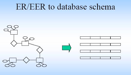
10 Transforming E-R Diagrams into Relations It is useful to transform the conceptual data model into a set of normalized relations Steps 1. Represent entities 2. Represent relationships 3. Normalize the relations 4. Merge the relations 9.10
11 Refining the ER Design for the COMPANY Database Change attributes that represent relationships into relationship types Determine cardinality ratio and participation constraint of each relationship type
12 ER Diagrams, Naming Conventions, and Design Issues
13
14 Design Choices for ER Conceptual Design Model concept first as an attribute Refined into a relationship if attribute is a reference to another entity type Attribute that exists in several entity types may be elevated to an independent entity type Can also be applied in the inverse
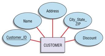
15 Attributes An entity is represented by a set of attributes, that is descriptive properties possessed by all members of an entity set. Example: Customer = (customer-id, customer-name, customer-street, customer-city) Loan = (loan-number, amount) Domain the set of permitted values for each attribute
16 Attributes Composite Key (identifier): Primary key composed of more than one attribute Composite attribute: Attribute that can be subdivided to yield additional attributes Simple attribute: Attribute that cannot be subdivided Single-valued attribute: Attribute that has only a single value Multivalued attributes: Attributes that have many values 16
17 Attributes Multivalued (Set Valued) attributes: Attributes that have many values and require creating: Several new attributes, one for each component of the original multivalued attribute A new entity composed of the original multivalued attribute s components Derived attribute: Attribute whose value is calculated from other attributes Derived using an algorithm 17

18 Figure Depiction of a Derived Attribute 18
19 Attribute types: Simple and Composite attributes. Single-valued and Multi-valued attributes E.g. multivalued attribute: phone-numbers Derived attributes Can be computed from other attributes E.g. age, given date of birth
20 Multivalued Attributes Normalization Required to First Nomal Form A multivalued attribute M of an entity E is represented by a separate table EM Table EM has attributes corresponding to the primary key of E and an attribute corresponding to multivalued attribute M Eg: Create Dept_Location table from Department table Dept_Location( Dnumber, Dlocation)
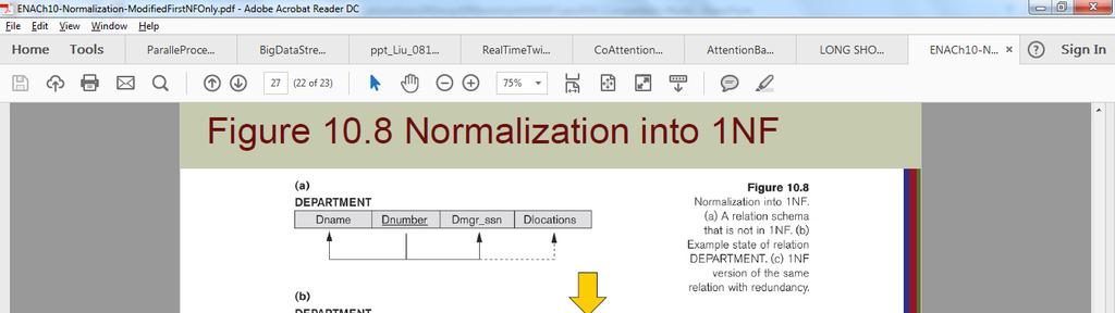

21 Multivalued Attribute: DLocations
22 Normalized in First Normal Form Department and Dept_Location DEPARTMENT DNAME DNUMBER MGRSSN MGRSTARTDAT E Headquarters Jun-71 Administration Jan-85 Research May-78 Automation Oct-05 DEPT_LOCATIONS DNUMBER DLOCATION 1 Houston 4 Stafford 5 Bellaire 5 Sugarland 5 Houston
23 Composite Attributes
24 Three Ways in Transforming Composite Attribute 1. Flatten the Structure to One Attribute eg: Address of Employee Table 2. Flatten the Structure to Multiple Attributes eg: Name Lname, MI, Fname of Employee Table 3. Making the Composite attribute to a Separate Table
25 Flatten the Structure to Transform Composite Attribute EMPLOYEE FNAME MINIT LNAME SSN BDATE ADDRESS S E X John B Smith Franklin T Wong Joyce A English Ramesh K Narayan James E Borg Jennife r S Wallace Ahmad V Jabbar Alicia J Zelaya SALARY SUPERSSN DNO 09-Jan Fondren, Houston, TX M Dec Voss, Houston, TX M Jul Rice, Houston, TX F Sep Fire Oak, Humble, TX M Nov Stone, Houston, TX M Jun Berry, Bellaire, TX F Mar Dallas, Houston, TX M Jul Castle, SPring, TX F
26 Option 3:Transforming Composite Attribute to a Table Option 3: Make a Composite Attribute into Separate Table Customer_Address Customer_Address (Customer_Id, Street_Number, Street_Name, Apt_Num, City, State, Zip, Country) More Query Power for Data Analytic on Address No Need to Access Big Customer Table for Address Analytics Required Join with Address Table and Customer Table for other Customer Information
27 Transforming Composite and Multivalued Attribute Make the Composite and Multi Valued Attribute to a Separate Table Customer_Address (Customer_Id, Street_Number, Street_Name, Apt_Num, City, State, Zip, Country)
28 Alternative Notations for ER Diagrams Specify structural constraints on Relationships Replaces Cardinality ratio (1:1, 1:N, M:N) and single/double line notation for Participation constraints Associate a pair of integer numbers (min, max) with each participation of an entity type E in a relationship type R, where 0 min max and max 1
29 Cardinality Ratio (1:1, 1:N, M:N) 1:N :Each dept has at most one manager on ssn name lot since did dname budget Manages. Employees Manages Departments Translation to relational model? 1-to-1 1-to Many Many-to-1 Many-to-Many
30
31 Transforming E-R Diagrams into Relations The primary key must satisfy the following two conditions 9.31 a. The value of the key must uniquely identify every row in the relation b. The key should be nonredundant
32 9.32
33 Transforming E-R Diagrams into Relations Represent Relationships Binary 1:N Relationships Add the Primary key attribute (or attributes) of the entity on the one side of the relationship as a Foreign key in the relation on the other (N) side The one side migrates to the many side 9.33
34 Constraints on Binary Relationship Types Cardinality ratio for a binary relationship Specifies maximum number of relationship instances that entity can participate in Participation Constraint Specifies whether existence of entity depends on its being related to another entity Types: total and partial
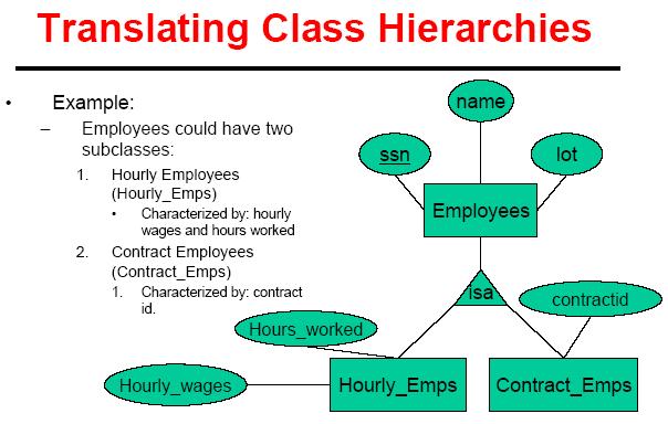
35 Attributes of Relationship Types Attributes of 1:1 or 1:N relationship types can be migrated to one entity type For a 1:N relationship type Relationship attribute can be migrated only to entity type on N-side of relationship For M:N relationship types Some attributes may be determined by combination of participating entities Must be specified as relationship attributes
36 Weak Entity Types Do not have key attributes of their own Identified by being related to specific entities from another entity type Identifying relationship Relates a weak entity type to its owner Always has a total participation constraint
37 9.37
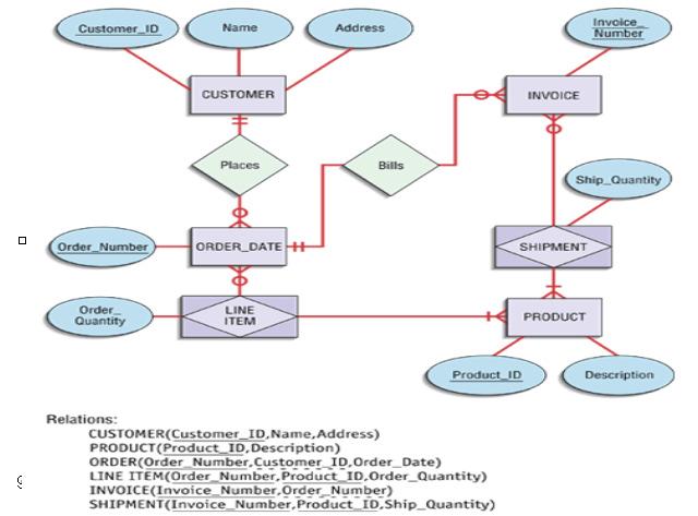
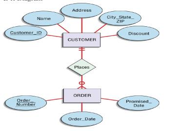
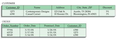
38 Transforming Binary 1:N Relationships into Relations Relationship: CUSTOMER Places ORDER(s) ORDER Table BEFORE Relationship: (Order_Number, Order_Date, Promised_Date) ORDER Table AFTER Relationship: (Order_Number, Order_Date, Promised_Date, Customer_ID) CREATE TABLE ORDER( Order_Number CHAR(1), Order_Date DATE, Promised_Date DATE, Customer_ID CHAR(1), PRIMARY KEY (Order_Number), FOREIGN KEY (Customer_ID) REFERENCES CUSTOMER(Customer_ID));
39 Transforming E-R Diagrams into Relations Binary or Unary 1:1 Three possible options a.add the primary key of A as a foreign key of B b.add the primary key of B as a foreign key of A c.both 9.39
40 Binary 1 To 1 Relationship Employee(Manager) MANAGES Department EMPLOYEE FNAME MINI LNAME SSN BDATE ADDRESS SEX SALARY SUPERSSN DNO T John B Smith Jan Fondren, Houston, M TX Frankli T Wong Dec Voss, Houston, TX M n Joyce A English Jul Rice, Houston, TX F Ramesh K Naraya Sep Fire Oak, Humble, M n TX James E Borg Nov Stone, Houston, TX M Jennife S Wallace Jun Berry, Bellaire, TX F r Ahmad V Jabbar Mar Dallas, Houston, TX M Alicia J Zelaya Jul Castle, SPring, TX F DEPARTMENT DNAME DNUMBER MGRSSN MGRSTARTD ATE Headquarters Jun-71 Administration Jan-85 Research May-78 Automation Oct-05
41 Transforming E-R Diagrams into Relations Represent Relationships Binary and higher M:N relationships Create another relation and include primary keys of all relations as primary key of new relation 9.41
42 9.42
43 Association Class to Table ORDER LINE Order_ Number Product_ ID Quantity_ Ordered M A A R R149 2
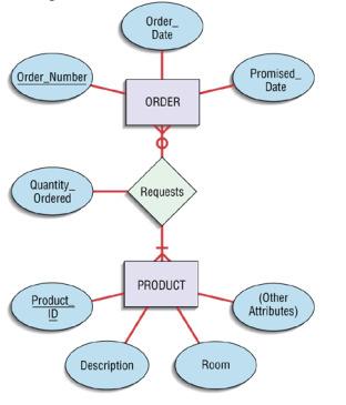
44 Transforming Binary M:N Relationships into Relations Relationship Requests: Order Requests Products 1. Create Table ORDERLINE for Relationship Requests 2. Add PK of each side of Tables ( Order_Number, Product_ID) as Foreign Keys 3. Make composite of both attributes as Primary Key of the Table ORDERLINE : ORDERLINE(Order_Number, Product_ID, Quantity_Ordered) CREATE TABLE ORDERLINE ( Order_Number CHAR(10), Product_ID Quantity_Ordered CHAR(10), Integer, PRIMARY KEY (Order_Number, Product_ID), FOREIGN KEY (Order_Numer) REFERENCES ORDER(Order_Number), FOREIGN KEY (Product_ID) REFERENCES PRODUCT(Product_ID));
45 Transforming E-R Diagrams into Relations Unary 1:N Relationships Relationship between instances of a single entity type Utilize a recursive foreign key A foreign key in a relation that references the primary key values of that same relation Unary M:N Relationships Create a separate relation Primary key of new relation is a composite of two attributes that both take their values from the same primary key 9.45
46 9.46
47 Unary 1 to M to Table: MANAGES Emp_ID Name Mgr_ID Birthdate John Smith / Jane Doe / Anne Hana / Nick Shaw / Ron Birkman 07/20
48 Transforming Unary 1:N Relationships into Relations Relationship: EMPLOYEE (as Manager) Manages EMPLOYEE EMPLOYEE Table BEFORE Relationship: (Emp_ID, Name, Birthday) EMPLOYEE Table AFTER Relationship: (Emp_ID, Name, Birthday, Mgr_ID) CREATE TABLE EMPLOYEE( Emp_ID CHAR(1), Name Varchar(30), Birthday DATE, Mgr_ID CHAR(1), PRIMARY KEY (Emp_ID), FOREIGN KEY (Mgr_ID) REFERENCES EMPLOYEE (Emp_ID));
49 Unary Association Class to Table: CONTAINS Item_ Number Containig Item_ Number Name Contained Item_ Number Cost A261 Nail AAA M128 Screw BBB CCC M A A R R149 2 Quantity
50 Transforming Unary M:N Relationships into Relations Relationship CONTAINS: ITEM Contains ITEM 1. Create Table for Relationship CONTAINS 2. Add PK of each side of Tables ( Containing_Item_Numer, Contained_Item_Numer) as Foreign Keys 3. Make composite of both attributes as Primary Key of the Table CONTAINS: CONTAINS (Containing_Item_Number, Contained_Item_Number, CREATE TABLE CONTAINS ( Containing_Item_Number CHAR(10), Contained_Item_Number CHAR(10), Quantity PRIMARY KEY (Containing_Item_Numer, Contained_Item_Numer), FOREIGN KEY (Containing_Item_Number) REFERENCES ITEM(Item_Number), FOREIGN KEY (Contained_Item_Number) REFERENCES ITEM(Item_Number)); Integer,
51 9.51
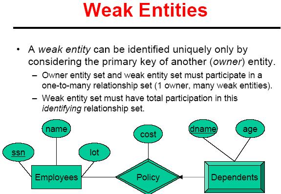
52 Review: Weak Entities A Weak Entity can be identified uniquely only by considering the primary key of another (owner) entity. Owner Entity set and Weak Entity set must participate in a one-to-many relationship set (1 owner, many weak entities). Weak entity set must have total participation in this identifying relationship set. ssn name lot cost dname age Employees Policy Dependents
53
54 Translating Weak Entity Sets Weak entity set and identifying relationship set are translated into a single table. When the owner entity is deleted, all owned weak entities must also be deleted. CREATE TABLE Dep_Policy ( dname CHAR(20), age INTEGER, cost REAL, ssn CHAR(11) NOT NULL, PRIMARY KEY (pname, ssn), FOREIGN KEY (ssn) REFERENCES Employees, ON DELETE CASCADE)
55

56
57 Primary Key Constraints A set of fields is a key for a relation if : 1. No two distinct tuples can have same values in all key fields, and 2. This is not true for any subset of the key. Key is minimal. However, 2 does not hold (so false) for superkey which is not minimal. If there s more than one keys for a relation, one of the keys is chosen (by DBA) to be the primary key. E.g., customer_id is a key for Customer. (What about name?) The set {customer_id, name} could be a superkey. Primary key can not have null value
58 Domain Constraint The value of each Attribute A with Domain Type D(A i ) must be a atomic value from the domain type D(A i ).
59 Definitions of Keys and Attributes Participating in Keys A superkey of a relation schema R = {A1, A2,..., An} is a set of attributes S, subset-of R, with the property that No two tuples t1 and t2 in any legal relation state r of R will have t1[s] = t2[s]. That is, for any given two tuples t1, t2 in data (extensions) of Relation schema R, t1[s] is not identical to t2[s]. A key K is a superkey with the additional property that removal of any attribute from K will cause K not to be a superkey any more; Key is minimal.
60 Definitions of Keys and Attributes Participating in Keys If a relation schema has more than one key, each is called a candidate key. One of the candidate keys is arbitrarily designated to be the primary key, and the others are called secondary keys. A Prime attribute must be a member of any (candidate) key A Nonprime attribute is not a prime attribute that is, it is not a member of any (candidate) key.
61 Foreign Keys, Referential Integrity Foreign key : Set of fields in one relation that is used to `refer to a tuple in another relation. (Must correspond to primary key of the second relation.) Like a `logical pointer. E.g. customer_id in Order is a foreign key referring to Customer: Order (order_number, order_date, promised_date, customer_id)
62 Foreign Keys, Referential Integrity If all foreign key constraints are enforced, referential integrity is achieved; all foreign key values should refer to existing values, i.e., no dangling references. Can you name a data model w/o referential integrity? Links in HTML!
63 Enforcing Referential Integrity Consider Students(sid, name, gpa) and Enrolled (rid, semester, sid); sid in Enrolled is a foreign key that references Students. What should be done if an Enrolled tuple with a non-existent student id is inserted? Reject it! What should be done if a Students tuple is deleted? Also delete all Enrolled tuples that refer to it. Disallow deletion of a Students tuple that is referred to. Set sid in Enrolled tuples that refer to it to a default sid. (In SQL, also: Set sid in Enrolled tuples that refer to it to a special value null, denoting `unknown or `inapplicable.) Similar if primary key of Students tuple is updated.
64 Logical DB Design: ER to Relational Entity sets to tables. ssn name lot Employees CREATE TABLE Employees (ssn CHAR(11), name CHAR(20), lot INTEGER, PRIMARY KEY (ssn))
65 Review: Key Constraints Each dept has at most one manager, according ssn name lot since did dname budget to the key constraint on Manages. Employees Manages Departments Translation to relational model? 1-to-1 1-to Many Many-to-1 Many-to-Many
66 Transforming 1:N, M:N Relationships with Key Constraints ER Diagram: ssn name lot since did dname budget Employees Manages Departments Works_In since
67 Translating ER Diagrams with Key Constraints Map relationship to a table: Note that did is the key here! Separate tables for Employees and Departments. Since each department has a unique manager, we could instead combine Manages and Departments. CREATE TABLE Manages( ssn CHAR(11), did INTEGER, since DATE, PRIMARY KEY (did), FOREIGN KEY (ssn) REFERENCES Employees, FOREIGN KEY (did) REFERENCES Departments) CREATE TABLE Dept_Mgr( did INTEGER, dname CHAR(20), budget REAL, ssn CHAR(11), since DATE, PRIMARY KEY (did), FOREIGN KEY (ssn) REFERENCES Employees)
68 Transforming Realtionship to Tables Example E-R diagram: ssn name lot since did dname budget Employees Manages Departments Works_In since
69 Relationship Sets to Tables In translating a relationship Works_In (M-N) to a relation, attributes of the relation must include: Keys for each participating entity set (as foreign keys). CREATE TABLE Works_In( ssn CHAR(1), did INTEGER, since DATE, PRIMARY KEY (ssn, did), FOREIGN KEY (ssn) REFERENCES Employees, FOREIGN KEY (did) REFERENCES Departments) This set of attributes forms a superkey for the relation. All descriptive attributes.
70 Review: Participation Constraints Does every department have a manager? If so, this is a participation constraint: the participation of Departments in Manages is said to be total (vs. partial). Every did value in Departments table must appear in a row of the Manages table (with a non-null ssn value!) ssn name lot since did dname budget Employees Manages Departments Works_In since
71 Participation Constraints in SQL We can capture participation constraints involving one entity set in a binary relationship, but little else (without resorting to CHECK constraints). CREATE TABLE Dept_Mgr( did INTEGER, dname CHAR(20), budget REAL, ssn CHAR(11) NOT NULL, since DATE, PRIMARY KEY (did), FOREIGN KEY (ssn) REFERENCES Employees, ON DELETE NO ACTION)
72 Review: Binary vs. Ternary Relationships ssn name lot dname age If each policy is owned by just 1 employee: Employees Bad design Covers Policies Dependents Key constraint on Policies would mean policy can only cover 1 dependent! What are the additional constraints in the 2nd diagram? name ssn Employees policyid cost dname age lot Dependents Purchaser Better design Beneficiary Policies policyid cost
73 The key constraints allow us to combine Binary vs. Ternary Relationships (Contd.) Purchaser with Policies and Beneficiary with Dependents. Participation constraints lead to NOT NULL constraints. What if Policies is a weak entity set? PK of Policies: (policyid, ssn) PK of Dependents: (dname, policyid, ssn) CREATE TABLE Policies ( policyid INTEGER, cost REAL, ssn CHAR(11) NOT NULL, PRIMARY KEY (policyid). FOREIGN KEY (ssn) REFERENCES Employees, ON DELETE CASCADE); CREATE TABLE Dependents ( dname CHAR(20), age INTEGER, policyid INTEGER, PRIMARY KEY (dname, policyid). FOREIGN KEY (policyid) REFERENCES Policies ON DELETE CASCADE);
74 An Example CREATE TABLE Student ( ID NUMBER, Fname VARCHAR2(20), Lname VARCHAR2(20), );
75 Constraints in Create Table Adding constraints to a table enables the database system to enforce data integrity. Different types of constraints: * Not Null * Default Values * Unique * Primary Key * Foreign Key * Check Condition
76 Not Null Constraint CREATE TABLE Student ( ID NUMBER, Fname VARCHAR2(20) NOT NULL, Lname VARCHAR2(20) NOT NULL, );
77 Primary Key Constraint CREATE TABLE Student ( ID NUMBER PRIMARY KEY, Fname VARCHAR2(20) NOT NULL, Lname VARCHAR2(20) NOT NULL, ); Primary Key implies: * NOT NULL * UNIQUE. There can only be one primary key.
78 Primary Key Constraint (Syntax 2) CREATE TABLE Students ( ID NUMBER, Fname VARCHAR2(20) NOT NULL, Lname VARCHAR2(20) NOT NULL, PRIMARY KEY(ID) ); Needed when the primary key is made up of two or more attributes (fields)
79 Foreign Key Constraint CREATE TABLE Studies( Course NUMBER, Student NUMBER, FOREIGN KEY (Student) REFERENCES Students(ID) ); NOTE: ID must be unique (or primary key) in Students table
Translation of ER-diagram into Relational Schema. Dr. Sunnie S. Chung CIS430/530
 Translation of ER-diagram into Relational Schema Dr. Sunnie S. Chung CIS430/530 Learning Objectives Define each of the following database terms 9.2 Relation Primary key Foreign key Referential integrity
Translation of ER-diagram into Relational Schema. Dr. Sunnie S. Chung CIS430/530
 Translation of ER-diagram into Relational Schema Dr. Sunnie S. Chung CIS430/530 Learning Objectives Define each of the following database terms Relation Primary key Foreign key Referential integrity Field
Part 1 on Table Function
 CIS611 Lab Assignment 1 SS Chung 1. Write Table Functions 2. Automatic Creation and Maintenance of Database from Web Interface 3. Transforming a SQL Query into an Execution Plan in Relational Algebra for
CIS611 Lab Assignment 1 SS Chung
 CIS611 Lab Assignment 1 SS Chung 1. Creating a Relational Database Schema from ER Diagram, Populating the Database and Querying Over the database with SQL 2. Automatic Creation and Maintenance of Database
Database design process
 Database technology Lecture 2: Relational databases and SQL Jose M. Peña jose.m.pena@liu.se Database design process 1 Relational model concepts... Attributes... EMPLOYEE FNAME M LNAME SSN BDATE ADDRESS
Dr. Anis Koubaa. Advanced Databases SE487. Prince Sultan University
 Advanced Databases Prince Sultan University College of Computer and Information Sciences Fall 2013 Chapter 15 Basics of Functional Dependencies and Normalization for Relational Databases Anis Koubaa SE487
The Relational Model. Chapter 3. Comp 521 Files and Databases Fall
 The Relational Model Chapter 3 Comp 521 Files and Databases Fall 2012 1 Why Study the Relational Model? Most widely used model by industry. IBM, Informix, Microsoft, Oracle, Sybase, etc. It is simple,
COSC344 Database Theory and Applications. σ a= c (P) S. Lecture 4 Relational algebra. π A, P X Q. COSC344 Lecture 4 1
 S. Lecture 4 Relational algebra. π A, P X Q. COSC344 Lecture 4 1") COSC344 Database Theory and Applications σ a= c (P) S π A, C (H) P P X Q Lecture 4 Relational algebra COSC344 Lecture 4 1 Overview Last Lecture Relational Model This Lecture ER to Relational mapping Relational
COSC344 Database Theory and Applications σ a= c (P) S π A, C (H) P P X Q Lecture 4 Relational algebra COSC344 Lecture 4 1 Overview Last Lecture Relational Model This Lecture ER to Relational mapping Relational
The Relational Model. Chapter 3
 The Relational Model Chapter 3 Why Study the Relational Model? Most widely used model. Systems: IBM DB2, Informix, Microsoft (Access and SQL Server), Oracle, Sybase, MySQL, etc. Legacy systems in older
The Relational Model. Chapter 3. Database Management Systems, R. Ramakrishnan and J. Gehrke 1
 The Relational Model Chapter 3 Database Management Systems, R. Ramakrishnan and J. Gehrke 1 Why Study the Relational Model? Most widely used model. Vendors: IBM, Informix, Microsoft, Oracle, Sybase, etc.
Session Active Databases (2+3 of 3)
") INFO-H-415 - Advanced Databes Session 2+3 - Active Databes (2+3 of 3) Consider the following databe schema: DeptLocation DNumber DLocation Employee FName MInit LName SSN BDate Address Sex Salary SuperSSN
INFO-H-415 - Advanced Databes Session 2+3 - Active Databes (2+3 of 3) Consider the following databe schema: DeptLocation DNumber DLocation Employee FName MInit LName SSN BDate Address Sex Salary SuperSSN
The Relational Model 2. Week 3
 The Relational Model 2 Week 3 1 We have seen how to create a database schema, how do we create an actual database on our computers? professor(pid : string, name : string) course(pid : string, number :
The Relational Model. Chapter 3. Comp 521 Files and Databases Fall
 The Relational Model Chapter 3 Comp 521 Files and Databases Fall 2014 1 Why the Relational Model? Most widely used model by industry. IBM, Informix, Microsoft, Oracle, Sybase, MySQL, Postgres, Sqlite,
COSC Assignment 2
 COSC 344 Overview In this assignment, you will turn your miniworld into a set of Oracle tables, normalize your design, and populate your database. Due date for assignment 2 Friday, 25 August 2017 at 4
Overview Relational data model
 Thanks to José and Vaida for most of the slides. Relational databases and MySQL Juha Takkinen juhta@ida.liu.se Outline 1. Introduction: Relational data model and SQL 2. Creating tables in Mysql 3. Simple
Database Technology. Topic 2: Relational Databases and SQL. Olaf Hartig.
 Topic 2: Relational Databases and SQL Olaf Hartig olaf.hartig@liu.se Relational Data Model Recall: DB Design Process 3 Relational Model Concepts Relational database: represent data as a collection of relations
The Relational Model. Why Study the Relational Model? Relational Database: Definitions
 The Relational Model Database Management Systems, R. Ramakrishnan and J. Gehrke 1 Why Study the Relational Model? Most widely used model. Vendors: IBM, Microsoft, Oracle, Sybase, etc. Legacy systems in
Some different database system architectures. (a) Shared nothing architecture.
 Shared nothing architecture.") Figure.1 Some different database system architectures. (a) Shared nothing architecture. Computer System 1 Computer System CPU DB CPU DB MEMORY MEMORY Switch Computer System n CPU DB MEMORY Figure.1 continued.
Figure.1 Some different database system architectures. (a) Shared nothing architecture. Computer System 1 Computer System CPU DB CPU DB MEMORY MEMORY Switch Computer System n CPU DB MEMORY Figure.1 continued.
In Chapters 3 through 6, we presented various aspects
 15 chapter Basics of Functional Dependencies and Normalization for Relational Databases In Chapters 3 through 6, we presented various aspects of the relational model and the languages associated with it.
Database Technology. Topic 3: SQL. Olaf Hartig.
 Olaf Hartig olaf.hartig@liu.se Structured Query Language Declarative language (what data to get, not how) Considered one of the major reasons for the commercial success of relational databases Statements
Querying a Relational Database COMPANY database For Lab4, you use the Company database that you built in Lab2 and used for Lab3
 CIS30/530 Lab Assignment SS Chung Querying a Relational Database COMPANY database For Lab, you use the Company database that you built in Lab2 and used for Lab3 1. Update the following new changes into
Data Modeling. Yanlei Diao UMass Amherst. Slides Courtesy of R. Ramakrishnan and J. Gehrke
 Data Modeling Yanlei Diao UMass Amherst Slides Courtesy of R. Ramakrishnan and J. Gehrke 1 Outline v Conceptual Design: ER Model v Relational Model v Logical Design: from ER to Relational 2 Conceptual
Database Applications (15-415)
") Database Applications (15-415) The Relational Model Lecture 3, January 18, 2015 Mohammad Hammoud Today Last Session: The entity relationship (ER) model Today s Session: ER model (Cont d): conceptual design
Database Applications (15-415) The Relational Model Lecture 3, January 18, 2015 Mohammad Hammoud Today Last Session: The entity relationship (ER) model Today s Session: ER model (Cont d): conceptual design
High Level Database Models
 ICS 321 Fall 2011 High Level Database Models Asst. Prof. Lipyeow Lim Information & Computer Science Department University of Hawaii at Manoa 9/21/2011 Lipyeow Lim -- University of Hawaii at Manoa 1 Database
The Relational Model. Outline. Why Study the Relational Model? Faloutsos SCS object-relational model
 The Relational Model CMU SCS 15-415 C. Faloutsos Lecture #3 R & G, Chap. 3 Outline Introduction Integrity constraints (IC) Enforcing IC Querying Relational Data ER to tables Intro to Views Destroying/altering
Introduction to Data Management. Lecture #4 (E-R Relational Translation)
") Introduction to Data Management Lecture #4 (E-R Relational Translation) Instructor: Mike Carey mjcarey@ics.uci.edu Database Management Systems 3ed, R. Ramakrishnan and J. Gehrke 1 Announcements v Today
Introduction to Data Management Lecture #4 (E-R Relational Translation) Instructor: Mike Carey mjcarey@ics.uci.edu Database Management Systems 3ed, R. Ramakrishnan and J. Gehrke 1 Announcements v Today
The Entity-Relationship Model. Overview of Database Design
 The Entity-Relationship Model Chapter 2, Chapter 3 (3.5 only) Database Management Systems 3ed, R. Ramakrishnan and J. Gehrke 1 Overview of Database Design Conceptual design: (ER Model is used at this stage.)
Advanced Databases. Winter Term 2012/13. Prof. Dr. Dietmar Seipel University of Würzburg. Advanced Databases Winter Term 2012/13
 Advanced Databases Winter Term 2012/13 Prof. Dr. Dietmar Seipel University of Würzburg Prof. Dr. Dietmar Seipel Minit FName LName Sex Adress Salary N WORKS_FOR 1 Name Number Locations Name SSN EMPLOYEE
Query 2: Pnumber Dnum Lname Address Bdate 10 4 Wallace 291 Berry, Bellaire, TX Wallace 291 Berry, Bellaire, TX
 5.11 No violation, integrity is retained. Dnum = 2 does not exist. This can be solved by adding a foreign key referencing the department table, so the operation does not execute. Dnum = 4 already exists,
Database Systems. Lecture2:E-R model. Juan Huo( 霍娟 )
") Database Systems Lecture2:E-R model Juan Huo( 霍娟 ) Reference slides: http://www.cs.wisc.edu/ dbbook Berkeley, Professor Eben Haber,Professor Mary Roth Review: Benefits of a DBMS 1. Data independence applications
Database Systems Lecture2:E-R model Juan Huo( 霍娟 ) Reference slides: http://www.cs.wisc.edu/ dbbook Berkeley, Professor Eben Haber,Professor Mary Roth Review: Benefits of a DBMS 1. Data independence applications
Why Study the Relational Model? The Relational Model. Relational Database: Definitions. The SQL Query Language. Relational Query Languages
 Why Study the Relational Model? The Relational Model Most widely used model. Vendors: IBM, Informix, Microsoft, Oracle, Sybase, etc. Legacy systems in older models E.G., IBM s IMS Recent competitor: object-oriented
The Relational Model (ii)
") ICS 321 Fall 2009 The Relational Model (ii) Asst. Prof. Lipyeow Lim Information and Computer Science Department University of Hawaii at Manoa 1 Internet Book Store Example Isbn title author qty price year
ICS 321 Fall 2009 The Relational Model (ii) Asst. Prof. Lipyeow Lim Information and Computer Science Department University of Hawaii at Manoa 1 Internet Book Store Example Isbn title author qty price year
ECE 650 Systems Programming & Engineering. Spring 2018
 ECE 650 Systems Programming & Engineering Spring 2018 Relational Databases: Tuples, Tables, Schemas, Relational Algebra Tyler Bletsch Duke University Slides are adapted from Brian Rogers (Duke) Overview
PES Institute of Technology Bangalore South Campus (1 K.M before Electronic City,Bangalore ) Department of MCA. Solution Set - Test-II
 Department of MCA. Solution Set - Test-II") PES Institute of Technology Bangalore South Campus (1 K.M before Electronic City,Bangalore 560100 ) Solution Set - Test-II Sub: Database Management Systems 16MCA23 Date: 04/04/2017 Sem & Section:II Duration:
PES Institute of Technology Bangalore South Campus (1 K.M before Electronic City,Bangalore 560100 ) Solution Set - Test-II Sub: Database Management Systems 16MCA23 Date: 04/04/2017 Sem & Section:II Duration:
Overview of Database Design Process Example Database Application (COMPANY) ER Model Concepts
 ER Model Concepts") Chapter Outline Overview of Database Design Process Example Database Application (COMPANY) ER Model Concepts Entities and Attributes Entity Types, Value Sets, and Key Attributes Relationships and Relationship
Chapter Outline Overview of Database Design Process Example Database Application (COMPANY) ER Model Concepts Entities and Attributes Entity Types, Value Sets, and Key Attributes Relationships and Relationship
CONCEPTUAL DESIGN: ER TO RELATIONAL TO SQL
 RELATIONAL MODEL TO Data Model CONCEPTUAL DESIGN: ER TO RELATIONAL TO How to represent Entity sets, Relationship sets, Attributes, Key and participation constraints, Subclasses, Weak entity sets...? 2
CIS 330: Applied Database Systems. ER to Relational Relational Algebra
 CIS 330: Applied Database Systems ER to Relational Relational Algebra 1 Logical DB Design: ER to Relational Entity sets to tables: ssn name Employees lot CREATE TABLE Employees (ssn CHAR(11), name CHAR(20),
Relational Model. CS 377: Database Systems
 Relational Model CS 377: Database Systems ER Model: Recap Recap: Conceptual Models A high-level description of the database Sufficiently precise that technical people can understand it But, not so precise
The Relational Model. Roadmap. Relational Database: Definitions. Why Study the Relational Model? Relational database: a set of relations
 The Relational Model CMU SCS 15-415/615 C. Faloutsos A. Pavlo Lecture #3 R & G, Chap. 3 Roadmap Introduction Integrity constraints (IC) Enforcing IC Querying Relational Data ER to tables Intro to Views
Introduction to Data Management. Lecture #5 Relational Model (Cont.) & E-Rà Relational Mapping
 & E-Rà Relational Mapping") Introduction to Data Management Lecture #5 Relational Model (Cont.) & E-Rà Relational Mapping Instructor: Mike Carey mjcarey@ics.uci.edu Database Management Systems 3ed, R. Ramakrishnan and J. Gehrke 1
Introduction to Data Management Lecture #5 Relational Model (Cont.) & E-Rà Relational Mapping Instructor: Mike Carey mjcarey@ics.uci.edu Database Management Systems 3ed, R. Ramakrishnan and J. Gehrke 1
High-Level Database Models (ii)
") ICS 321 Spring 2011 High-Level Database Models (ii) Asst. Prof. Lipyeow Lim Information & Computer Science Department University of Hawaii at Manoa 1 Logical DB Design: ER to Relational Entity sets to
ICS 321 Spring 2011 High-Level Database Models (ii) Asst. Prof. Lipyeow Lim Information & Computer Science Department University of Hawaii at Manoa 1 Logical DB Design: ER to Relational Entity sets to
Relational Databases BORROWED WITH MINOR ADAPTATION FROM PROF. CHRISTOS FALOUTSOS, CMU /615
 Relational Databases BORROWED WITH MINOR ADAPTATION FROM PROF. CHRISTOS FALOUTSOS, CMU 15-415/615 Roadmap 3 Introduction Integrity constraints (IC) Enforcing IC Querying Relational Data ER to tables Intro
Relational Model. Topics. Relational Model. Why Study the Relational Model? Linda Wu (CMPT )
") Topics Relational Model Linda Wu Relational model SQL language Integrity constraints ER to relational Views (CMPT 354 2004-2) Chapter 3 CMPT 354 2004-2 2 Why Study the Relational Model? Most widely used
Topics Relational Model Linda Wu Relational model SQL language Integrity constraints ER to relational Views (CMPT 354 2004-2) Chapter 3 CMPT 354 2004-2 2 Why Study the Relational Model? Most widely used
Database Systems ( 資料庫系統 )
") Database Systems ( 資料庫系統 ) 9.28.2011 Lecture #3 1 Course Administration Please download HW #1 from course homepage It is due 10/12/2011. This lecture: R&G Chapter 3 Next week reading: R&G Chapter 41~ 4.1
Database Systems ( 資料庫系統 ) 9.28.2011 Lecture #3 1 Course Administration Please download HW #1 from course homepage It is due 10/12/2011. This lecture: R&G Chapter 3 Next week reading: R&G Chapter 41~ 4.1
EGCI 321: Database Systems. Dr. Tanasanee Phienthrakul
 1 EGCI 321: Database Systems Dr. Tanasanee Phienthrakul 2 Chapter 10 Data Definition Language (DDL) 3 Basic SQL SQL language Considered one of the major reasons for the commercial success of relational
Guides for Installing MS SQL Server and Creating Your First Database. Please see more guidelines on installing procedure on the class webpage
 Guides for Installing MS SQL Server and Creating Your First Database Installing process Please see more guidelines on installing procedure on the class webpage 1. Make sure that you install a server with
Using High-Level Conceptual Data Models for Database Design A Sample Database Application Entity Types, Entity Sets, Attributes, and Keys
 Chapter 7: Data Modeling Using the Entity- Relationship (ER) Model Using High-Level Conceptual Data Models for Database Design A Sample Database Application Entity Types, Entity Sets, Attributes, and Keys
Introduction to Data Management. Lecture #4 (E-R à Relational Design)
") Introduction to Data Management Lecture #4 (E-R à Relational Design) Instructor: Mike Carey mjcarey@ics.uci.edu Database Management Systems 3ed, R. Ramakrishnan and J. Gehrke 1 Announcements v Reminders:
Introduction to Data Management Lecture #4 (E-R à Relational Design) Instructor: Mike Carey mjcarey@ics.uci.edu Database Management Systems 3ed, R. Ramakrishnan and J. Gehrke 1 Announcements v Reminders:
Chapter Outline. Note 1. Overview of Database Design Process Example Database Application (COMPANY) ER Model Concepts
 ER Model Concepts") Chapter Outline Overview of Database Design Process Example Database Application (COMPANY) ER Model Concepts Entities and Attributes Entity Types, Value Sets, and Key Attributes Relationships and Relationship
Chapter Outline Overview of Database Design Process Example Database Application (COMPANY) ER Model Concepts Entities and Attributes Entity Types, Value Sets, and Key Attributes Relationships and Relationship
The Relational Model
 The Relational Model UVic C SC 370, Fall 2002 Daniel M. German Department of Computer Science University of Victoria 3 1 The Relational Model CSC 370 dmgerman@uvic.ca Overview How is data represented in
Relational Database Systems Part 01. Karine Reis Ferreira
 Relational Database Systems Part 01 Karine Reis Ferreira karine@dpi.inpe.br Aula da disciplina Computação Aplicada I (CAP 241) 2016 Database System Database: is a collection of related data. represents
Database Management System (15ECSC208) UNIT I: Chapter 2: Relational Data Model and Relational Algebra
 UNIT I: Chapter 2: Relational Data Model and Relational Algebra") Database Management System (15ECSC208) UNIT I: Chapter 2: Relational Data Model and Relational Algebra Relational Data Model and Relational Constraints Part 1 A simplified diagram to illustrate the main
Database Management System (15ECSC208) UNIT I: Chapter 2: Relational Data Model and Relational Algebra Relational Data Model and Relational Constraints Part 1 A simplified diagram to illustrate the main
Conceptual Design. The Entity-Relationship (ER) Model
 Model") Conceptual Design. The Entity-Relationship (ER) Model CS430/630 Lecture 12 Slides based on Database Management Systems 3 rd ed, Ramakrishnan and Gehrke Database Design Overview Conceptual design The Entity-Relationship
Conceptual Design. The Entity-Relationship (ER) Model CS430/630 Lecture 12 Slides based on Database Management Systems 3 rd ed, Ramakrishnan and Gehrke Database Design Overview Conceptual design The Entity-Relationship
Database Management Systems. Chapter 3 Part 2
 Database Management Systems Chapter 3 Part 2 The Relational Model Database Management Systems 3ed, R. Ramakrishnan and J. Gehrke 1 Logical DB Design: ER to Relational Entity sets to tables: CREATE TABLE
Chapter 6: RELATIONAL DATA MODEL AND RELATIONAL ALGEBRA
 Chapter 6: Relational Data Model and Relational Algebra 1 Chapter 6: RELATIONAL DATA MODEL AND RELATIONAL ALGEBRA RELATIONAL MODEL CONCEPTS The relational model represents the database as a collection
A database can be modeled as: + a collection of entities, + a set of relationships among entities.
 The Relational Model Lecture 2 The Entity-Relationship Model and its Translation to the Relational Model Entity-Relationship (ER) Model + Entity Sets + Relationship Sets + Database Design Issues + Mapping
Data Modeling Using the Entity-Relationship (ER) Model
 Model") CHAPTER 3 Data Modeling Using the Entity-Relationship (ER) Model Copyright 2017 Ramez Elmasri and Shamkant B. Navathe Slide 1-1 Chapter Outline Overview of Database Design Process Example Database Application
CHAPTER 3 Data Modeling Using the Entity-Relationship (ER) Model Copyright 2017 Ramez Elmasri and Shamkant B. Navathe Slide 1-1 Chapter Outline Overview of Database Design Process Example Database Application
RELATIONAL DATA MODEL
 RELATIONAL DATA MODEL 3.1 Introduction The relational model of data was introduced by Codd (1970). It is based on a simple and uniform data structure - the relation - and has a solid theoretical and mathematical
Database Systems ER Model. A.R. Hurson 323 CS Building
 ER Model A.R. Hurson 323 CS Building Database Design Data model is a group of concepts that helps to specify the structure of a database and a set of associated operations allowing data retrieval and data
Data Modeling with the Entity Relationship Model. CS157A Chris Pollett Sept. 7, 2005.
 Data Modeling with the Entity Relationship Model CS157A Chris Pollett Sept. 7, 2005. Outline Conceptual Data Models and Database Design An Example Application Entity Types, Sets, Attributes and Keys Relationship
The Entity-Relationship Model
 The Entity-Relationship Model Chapter 2 Instructor: Vladimir Zadorozhny vladimir@sis.pitt.edu Information Science Program School of Information Sciences, University of Pittsburgh 1 Database: a Set of Relations
L12: ER modeling 5. CS3200 Database design (sp18 s2) 2/22/2018
 2/22/2018") L12: ER modeling 5 CS3200 Database design (sp18 s2) https://course.ccs.neu.edu/cs3200sp18s2/ 2/22/2018 200 Announcements! Keep bringing your name plates J Exam 1 discussion: questions on grading: Piazza,
L12: ER modeling 5 CS3200 Database design (sp18 s2) https://course.ccs.neu.edu/cs3200sp18s2/ 2/22/2018 200 Announcements! Keep bringing your name plates J Exam 1 discussion: questions on grading: Piazza,
MIS Database Systems Entity-Relationship Model.
 MIS 335 - Database Systems Entity-Relationship Model http://www.mis.boun.edu.tr/durahim/ Ahmet Onur Durahim Learning Objectives Database Design Main concepts in the ER model? ER Diagrams Database Design
Entity Relationship Data Model. Slides by: Shree Jaswal
 Entity Relationship Data Model Slides by: Shree Jaswal Topics: Conceptual Modeling of a database, The Entity-Relationship (ER) Model, Entity Types, Entity Sets, Attributes, and Keys, Relationship Types,
CS 405G: Introduction to Database Systems
 CS 405G: Introduction to Database Systems Entity Relationship Model Jinze Liu 9/11/2014 1 CS685 : Special The UNIVERSITY Topics in Data of Mining, KENTUCKY UKY Review A database is a large collection of
EECS 647: Introduction to Database Systems
 EECS 647: Introduction to Database Systems Instructor: Luke Huan Spring 2009 Administrative I have communicated with KU Bookstore inquring about the text book status. Take home background survey is due
1/24/2012. Chapter 7 Outline. Chapter 7 Outline (cont d.) CS 440: Database Management Systems
 CS 440: Database Management Systems") CS 440: Database Management Systems Chapter 7 Outline Using High-Level Conceptual Data Models for Database Design A Sample Database Application Entity Types, Entity Sets, Attributes, and Keys Relationship
CS 440: Database Management Systems Chapter 7 Outline Using High-Level Conceptual Data Models for Database Design A Sample Database Application Entity Types, Entity Sets, Attributes, and Keys Relationship
From ER to Relational Model. Book Chapter 3 (part 2 )
") From ER to Relational Model Book Chapter 3 (part 2 ) Logical DB Design: ER to Relational Translate Entity sets to tables: ssn name Employees lot CREATE TABLE Employees (ssn CHAR(11), name CHAR(20), lot
From ER to Relational Model Book Chapter 3 (part 2 ) Logical DB Design: ER to Relational Translate Entity sets to tables: ssn name Employees lot CREATE TABLE Employees (ssn CHAR(11), name CHAR(20), lot
Database Systems. Course Administration
 Database Systems ( ) September 20, 2004 Lecture #2 By Hao-hua Chu ( ) 1 Course Administration Can everyone get the textbook? HW #1 is out on the course homepage It is due one week from today. Next week
The Relational Model. Week 2
 The Relational Model Week 2 1 Relations A relation is a more concrete construction, of something we have seen before, the ER diagram. name S.S.N students street city A relation is (just!) a table! We will
CIS 330: Applied Database Systems
 1 CIS 330: Applied Database Systems Lecture 3: Introduction to ER Modeling The Relational Model Johannes Gehrke johannes@cs.cornell.edu http://www.cs.cornell.edu/johannes Announcements How many laptops
Databases Model the Real World. The Entity- Relationship Model. Conceptual Design. Steps in Database Design. ER Model Basics. ER Model Basics (Contd.
 The Entity- Relationship Model R &G - Chapter 2 A relationship, I think, is like a shark, you know? It has to constantly move forward or it dies. And I think what we got on our hands is a dead shark. Woody
COSC 304 Introduction to Database Systems. Entity-Relationship Modeling
 COSC 304 Introduction to Database Systems Entity-Relationship Modeling Dr. Ramon Lawrence University of British Columbia Okanagan ramon.lawrence@ubc.ca Conceptual Database Design Conceptual database design
Relational Algebra Part I. CS 377: Database Systems
 Relational Algebra Part I CS 377: Database Systems Recap of Last Week ER Model: Design good conceptual models to store information Relational Model: Table representation with structures and constraints
We shall represent a relation as a table with columns and rows. Each column of the table has a name, or attribute. Each row is called a tuple.
 Logical Database design Earlier we saw how to convert an unorganized text description of information requirements into a conceptual design, by the use of ER diagrams. The advantage of ER diagrams is that
Introduction to Data Management. Lecture #5 (E-R Relational, Cont.)
") Introduction to Data Management Lecture #5 (E-R Relational, Cont.) Instructor: Mike Carey mjcarey@ics.uci.edu Database Management Systems 3ed, R. Ramakrishnan and J. Gehrke 1 Announcements v HW#1 is due
Introduction to Data Management Lecture #5 (E-R Relational, Cont.) Instructor: Mike Carey mjcarey@ics.uci.edu Database Management Systems 3ed, R. Ramakrishnan and J. Gehrke 1 Announcements v HW#1 is due
Modeling Your Data. Chapter 2. cs542 1
 Modeling Your Data Chapter 2 cs542 1 Part II Discussion of the Model: Good Design/ Bad Design cs542 2 Design : The Obvious Use meaningful and descriptive s (it s for the human after all) Keep as simple
Overview of Database Design Process. Data Modeling Using the Entity- Relationship (ER) Model. Two main activities:
 Model. Two main activities:") 1 / 14 Overview of Database Design Process Example Database Application (COMPANY) ER Model Concepts Entities and Attributes Entity Types, Value Sets, and Key Attributes Relationships and Relationship Types
1 / 14 Overview of Database Design Process Example Database Application (COMPANY) ER Model Concepts Entities and Attributes Entity Types, Value Sets, and Key Attributes Relationships and Relationship Types
THE ENTITY- RELATIONSHIP (ER) MODEL CHAPTER 7 (6/E) CHAPTER 3 (5/E)
 MODEL CHAPTER 7 (6/E) CHAPTER 3 (5/E)") THE ENTITY- RELATIONSHIP (ER) MODEL CHAPTER 7 (6/E) CHAPTER 3 (5/E) 2 CHAPTER 7 OUTLINE Using High-Level, Conceptual Data Models for Database Design Entity-Relationship (ER) model Popular high-level conceptual
THE ENTITY- RELATIONSHIP (ER) MODEL CHAPTER 7 (6/E) CHAPTER 3 (5/E) 2 CHAPTER 7 OUTLINE Using High-Level, Conceptual Data Models for Database Design Entity-Relationship (ER) model Popular high-level conceptual
ER Model. Objectives (2/2) Electricite Du Laos (EDL) Dr. Kanda Runapongsa Saikaew, Computer Engineering, KKU 1
 Electricite Du Laos (EDL) Dr. Kanda Runapongsa Saikaew, Computer Engineering, KKU 1") ER Model Asst. Prof. Dr. Kanda Runapongsa Saikaew (krunapon@kku.ac.th) Dept of Computer Engineering Khon Kaen University Objectives (1/2) Relational Data Model Terminology of relational data model How
ER Model Asst. Prof. Dr. Kanda Runapongsa Saikaew (krunapon@kku.ac.th) Dept of Computer Engineering Khon Kaen University Objectives (1/2) Relational Data Model Terminology of relational data model How
OVERVIEW OF DATABASE DEVELOPMENT
 DATABASE SYSTEMS I WEEK 2: THE ENTITY-RELATIONSHIP MODEL OVERVIEW OF DATABASE DEVELOPMENT Requirements Analysis / Ideas High-Level Database Design Conceptual Database Design / Relational Database Schema
Advance Database Management System
 Advance Database Management System Conceptual Design Lecture- A simplified database design process Database Requirements UoD Requirements Collection and Analysis Functional Requirements A simplified database
The DBMS accepts requests for data from the application program and instructs the operating system to transfer the appropriate data.
 Managing Data Data storage tool must provide the following features: Data definition (data structuring) Data entry (to add new data) Data editing (to change existing data) Querying (a means of extracting
Relational data model
 Relational data model Iztok Savnik FAMNIT, 18/19 Why Study the Relational Model? Most widely used model. Vendors: IBM, Informix, Microsoft, Oracle, Sybase, etc. Legacy systems in older models E.G., IBM
Introduction to Data Management. Lecture #6 E-Rà Relational Mapping (Cont.)
") Introduction to Data Management Lecture #6 E-Rà Relational Mapping (Cont.) Instructor: Mike Carey mjcarey@ics.uci.edu Database Management Systems 3ed, R. Ramakrishnan and J. Gehrke 1 It s time again for...
Introduction to Data Management Lecture #6 E-Rà Relational Mapping (Cont.) Instructor: Mike Carey mjcarey@ics.uci.edu Database Management Systems 3ed, R. Ramakrishnan and J. Gehrke 1 It s time again for...
Advanced Databases (SE487) Prince Sultan University College of Computer and Information Sciences
 Prince Sultan University College of Computer and Information Sciences") Advanced Databases (SE487) Prince Sultan University College of Computer and Information Sciences ER to Relational Mapping Anis Koubaa Chapter 9 Outline } Relational Database Design Using ER-to-Relational
Advanced Databases (SE487) Prince Sultan University College of Computer and Information Sciences ER to Relational Mapping Anis Koubaa Chapter 9 Outline } Relational Database Design Using ER-to-Relational
Translating an ER Diagram to a Relational Schema
 Translating an ER Diagram to a Relational Schema CS386/586 Introduction to Database Systems, Lois Delcambre 1999-2009 Slide 1 Translate each entity set into a table, with keys. Entity set: represented
Introduction to SQL. ECE 650 Systems Programming & Engineering Duke University, Spring 2018
 Introduction to SQL ECE 650 Systems Programming & Engineering Duke University, Spring 2018 SQL Structured Query Language Major reason for commercial success of relational DBs Became a standard for relational
Copyright 2016 Ramez Elmasr and Shamkant B. Navathei
 CHAPTER 3 Data Modeling Using the Entity-Relationship (ER) Model Slide 1-2 Chapter Outline Overview of Database Design Process Example Database Application (COMPANY) ER Model Concepts Entities and Attributes
The Relational Data Model and Relational Database Constraints
 The Relational Data Model and Relational Database Constraints First introduced by Ted Codd from IBM Research in 1970, seminal paper, which introduced the Relational Model of Data representation. It is
Lecture4: Guidelines for good relational design Mapping ERD to Relation. Ref. Chapter3
 College of Computer and Information Sciences - Information Systems Dept. Lecture4: Guidelines for good relational design Mapping ERD to Relation. Ref. Chapter3 Prepared by L. Nouf Almujally & Aisha AlArfaj
The Relational Model
 The Relational Model UVic C SC 370, Fall 2002 Daniel M. German Department of Computer Science University of Victoria September 25, 2002 Version: 1.03 3 1 The Relational Model (1.03) CSC 370 dmgerman@uvic.ca
NOTE: DO NOT REMOVE THIS EXAM PAPER FROM THE EXAM VENUE
 Exams, Awards & Graduations NOTE: DO NOT REMOVE THIS EXAM PAPER FROM THE EXAM VENUE EXAM COVER SHEET EXAMINATION DETAILS Course Code/s: ISYS1055/1057 Course Name/s: Database Concepts Date of Exam: Sample
Relational Design 1 / 34
 Relational Design 1 / 34 Relational Design Basic design approaches. What makes a good design better than a bad design? How do we tell we have a "good" design? How to we go about creating a good design?
DEPARTMENT DNAME DNUMBER MGRNAME MGRSTARTDATE
 Figure D.1 A hierarchical schema. DEPARTMENT DNAME DNUMBER MGRNAME MGRSTARTDATE NAME SSN BDATE ADDRESS PNAME PNUMBER PLOCATION Figure D.2 Occurrences of Parent-Child Relationships. (a) Two occurrences
The Relational Model of Data (ii)
") ICS 321 Fall 2013 The Relational Model of Data (ii) Asst. Prof. Lipyeow Lim Information & Computer Science Department University of Hawaii at Manoa 1 Defining Relational Schema in SQL Two aspects: Data
ICS 321 Fall 2013 The Relational Model of Data (ii) Asst. Prof. Lipyeow Lim Information & Computer Science Department University of Hawaii at Manoa 1 Defining Relational Schema in SQL Two aspects: Data
DBMS. Relational Model. Module Title?
 Relational Model Why Study the Relational Model? Most widely used model currently. DB2,, MySQL, Oracle, PostgreSQL, SQLServer, Note: some Legacy systems use older models e.g., IBM s IMS Object-oriented
CS403- Database Management Systems Solved Objective Midterm Papers For Preparation of Midterm Exam
 CS403- Database Management Systems Solved Objective Midterm Papers For Preparation of Midterm Exam Question No: 1 ( Marks: 1 ) - Please choose one Which of the following is NOT a feature of Context DFD?
The Entity-Relationship (ER) Model 2
 Model 2") The Entity-Relationship (ER) Model 2 Week 2 Professor Jessica Lin Keys Differences between entities must be expressed in terms of attributes. A superkey is a set of one or more attributes which, taken
The Entity-Relationship (ER) Model 2 Week 2 Professor Jessica Lin Keys Differences between entities must be expressed in terms of attributes. A superkey is a set of one or more attributes which, taken
Course Notes on From Entity-Relationship Schemas to Relational Schemas
 Course Notes on From Entity-Relationship Schemas to Relational Schemas The chapter deals with practical database design: the construction of a relational schema from an E-R schema this stage of database