COMMUNICATION PROTOCOLS
|
|
|
- Philomena Beatrice Horn
- 5 years ago
- Views:
Transcription


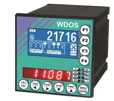
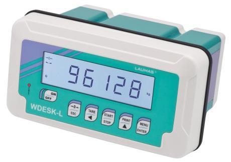
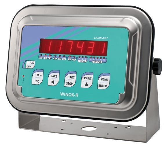
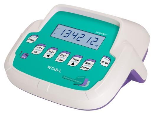
1 ENGLISH ENGLISH ENGLISH ENGLISH User Manual version 1.07 COMMUNICATION PROTOCOLS for weight indicators SERIES W (programs: BASE LOAD UNLOAD 3/6/14 PRODUCTS)
2 KEY TO SYMBOLS Below are the symbols used in the manual to draw the reader's attention: Caution! High Voltage. Caution! This operation must be performed by skilled workers. Read the following indications carefully. Further information.
3 TABLE OF CONTENTS CONTINUOUS FAST WEIGHT TRANSMISSION PROTOCOL - Only for BASE program... 1 CONTINUOUS WEIGHT TRANSMISSION TO REMOTE DISPLAYS PROTOCOL... 2 ASCII BIDIRECTIONAL PROTOCOL - Only for BASE program SETPOINT PROGRAMMING SELECTING THE CLASS OF SETPOINT (E/EC OPTION*) TO BE PROGRAMMED READING THE SELECTED CLASS OF SETPOINT (E/EC OPTION*) TO BE PROGRAMMED SETTING SETPOINT VALUES CURRENTLY IN USE SETPOINT STORAGE IN EEPROM MEMORY READING THE CLASS OF SETPOINT (E/EC OPTION*) CURRENTLY IN USE READING WEIGHT, SETPOINT AND PEAK (IF PRESENT) FROM PC SEMI-AUTOMATIC ZERO (WEIGHT ZERO-SETTING FOR SMALL VARIATIONS) SWITCHING FROM GROSS TO NET WEIGHT SWITCHING FROM NET TO GROSS WEIGHT READING OF DECIMALS AND DIVISION NUMBER TARE ZERO-SETTING REAL CALIBRATION (WITH SAMPLE WEIGHT) KEYPAD LOCK (BLOCK THE ACCESS TO THE INSTRUMENT) KEYPAD UNLOCK DISPLAY AND KEYPAD LOCK CHECK-SUM CALCULATION... 9 MODBUS-RTU PROTOCOL FUNCTIONS SUPPORTED IN MODBUS COMMUNICATION ERROR MANAGEMENT LIST OF AVAILABLE REGISTERS SPECIAL REGISTERS INPUTS AND OUTPUTS REGISTERS DIVISIONS AND UNITS OF MEASURE REGISTER (40014) POSSIBLE COMMANDS TO BE SENT TO THE COMMAND REGISTER (40006) REAL CALIBRATION COMMANDS (WITH SAMPLE WEIGHTS) ANALOG OUTPUT SETTING ONLY FOR BASE PROGRAM SETPOINT PROGRAMMING SETPOINT READING ONLY FOR BATCHING PROGRAMS (LOAD UNLOAD 3/6/14 PRODUCTS) CONSTANTS AND FORMULAS READING AND WRITING FORMULAS WRITING FORMULAS READING... 24
4 BATCHING START AND STOP BATCHING DATA READING BATCHING DATA ALARMS (40055; 40056) COMMUNICATION EXAMPLES CANOPEN TECHNICAL SPECIFICATIONS AND CONNECTIONS INSTRUMENT SETUP PC/PLC SETUP POSSIBLE COMMANDS TO BE SENT TO THE COMMAND REGISTER REAL CALIBRATION COMMANDS (WITH SAMPLE WEIGHTS) DEVICENET TECHNICAL SPECIFICATIONS AND CONNECTIONS INSTRUMENT SETUP PC/PLC SETUP POSSIBLE COMMANDS TO BE SENT TO THE COMMAND REGISTER REAL CALIBRATION COMMANDS (WITH SAMPLE WEIGHTS) ETHERNET TCP/IP TECHNICAL SPECIFICATIONS INSTRUMENT SETUP PC SETUP DIAGNOSTIC WEBSITE ETHERNET/IP TECHNICAL SPECIFICATIONS INSTRUMENT SETUP PC/PLC SETUP POSSIBLE COMMANDS TO BE SENT TO THE COMMAND REGISTER REAL CALIBRATION COMMANDS (WITH SAMPLE WEIGHTS) MODBUS/TCP TECHNICAL SPECIFICATIONS PC/PLC SETUP IP ADDRESS SETTING PROFIBUS TECHNICAL SPECIFICATIONS AND CONNECTIONS INSTRUMENT SETUP PC/PLC SETUP POSSIBLE COMMANDS TO BE SENT TO THE COMMAND REGISTER CONSTANTS AND FORMULAS READING AND WRITING FORMULAS WRITING... 65
5 FORMULAS READING BATCHING START AND STOP BATCHING DATA READING BATCHING DATA ALARMS (5; 6) REAL CALIBRATION COMMANDS (WITH SAMPLE WEIGHTS) PROFINET-IO TECHNICAL SPECIFICATIONS INSTRUMENT SETUP PC/PLC SETUP POSSIBLE COMMANDS TO BE SENT TO THE COMMAND REGISTER REAL CALIBRATION COMMANDS (WITH SAMPLE WEIGHTS) OUTPUTS AND INPUTS CONFIGURATION... 75
6 CONTINUOUS FAST WEIGHT TRANSMISSION PROTOCOL - Only for BASE program This protocol allows the continuous transmission of the weight at high update frequencies. Up to 300 strings per second are transmitted with a minimum transmission rate of baud. Following communication modes availables (see SERIAL COMMUNICATION SETTINGS section in instrument manual): : communication compatible with TX RS485 instruments : communication compatible with TD RS485 instruments If is set, the following string is transmitted to PC/PLC: xxxxxxcrlf where: xxxxxx... 6 characters of gross weight (48 57 ASCII) CR... 1 character return to the start (13 ASCII) LF... 1 character on new line (10 ASCII) In case of negative weight, the first character from the left of the weight characters takes on the value - (minus sign - ASCII 45). In case of error or alarm, the 6 characters of the weight are substituted by the messages found in the table of the ALARMS section (see the instrument manual). If is set, the following string is transmitted to PC/PLC: &TzzzzzzPzzzzzz\ckckCR where: &... 1 initial string character (38 ASCII) T... 1 character of gross weight identification P... 1 character of gross weight identification zzzzzz... 6 characters of gross weight (48 57 ASCII) \... 1 character of separation (92 ASCII) ckck... 2 ASCII control characters or calculated considering the characters included between & and \ excluded. The control value is obtained executing the XOR operation (exclusive OR) for the 8 bit ASCII codes of the characters considered. Therefore, a character expressed in hexadecimal is obtained with 2 numbers that may assume values from 0 to 9 and from A to F. ckck is the ASCII code of the two hexadecimal digits CR... 1 character of end string (13 ASCII) In case of negative weight, the first character from the left of the weight characters takes on the value - (minus sign - ASCII 45). In case of error or alarm, the 6 characters of the gross weight are substituted by the messages found in the table of the ALARMS section (see the instrument manual). FAST TRANSMISSION VIA EXTERNAL CONTACT: it s possible to transmit the weight, just once, even closing an input for no more than a second (see OUTPUTS AND INPUTS CONFIGURATION and SERIAL COMMUNICATION SETTINGS sections in instrument manual)
7 CONTINUOUS WEIGHT TRANSMISSION TO REMOTE DISPLAYS PROTOCOL This protocol allows the continuous weight transmission to remote displays. The communication string is transmitted 10 times per second. Following communication modes availables (see SERIAL COMMUNICATION SETTINGS section in instrument manual): - : communication with RIP5/20/60, RIP50SHA, RIPLED series remote displays; the remote display shows the net weight or gross weight according to its settings - : communication with RIP675, RIP6125C series remote displays; the remote display shows the net weight or gross weight according to its settings - : communication with RIP675, RIP6125C series remote displays The instrument sends the following string to the remote display: &NxxxxxxLyyyyyy\ckckCR where: &... 1 initial string character (38 ASCII) N... 1 character of net weight identification (78 ASCII) xxxxxx... 6 characters of net weight or PEAK if present (48 57 ASCII) L... 1 character of gross weight identification (76 ASCII) yyyyyy... 6 characters of gross weight (48 57 ASCII) \... 1 character of separation (92 ASCII) ckck... 2 ASCII checksum characters calculated considering the characters between & and \ excluded. The checksum value is obtained from the calculation of XOR (exclusive OR) of the 8-bit ASCII codes of the characters considered. This obtains a character expressed in hexadecimals with two digits that can have the values from 0 to 9 and from A to F. ckck is the ASCII code of the two hexadecimal digits CR... 1 character of end string (13 ASCII) In case of negative weight, the first character from the left of the weight characters takes on the value - (minus sign - ASCII 45). If has been set, the decimal point at the position shown on the instrument's display can also be transmitted. In this case, if the value exceeds 5 digits, only the 5 most significant digits are transmitted, while if the value is negative, no more than the 4 most significant digits are transmitted. In both cases, however, the decimal point shifts consistently with the value to display. If has been set, in addition to what stated in protocol, the instrument transmits the prompt every 4 seconds in the gross weight field, if on the instrument, it has been carried out a net operation (see SEMI-AUTOMATIC TARE (NET/GROSS) section in instrument manual). In case of weight value is under , the minus sign - is sent alternated with the most significant figure. In case of error or alarm, the 6 characters of the gross weight and net weight are substituted by the messages found in the table of the ALARMS section (see the instrument manual)
8 ASCII BIDIRECTIONAL PROTOCOL - Only for BASE program The instrument replies to the requests sent from a PC/PLC. It is possible to set a waiting time for the instrument before it transmits a response (see parameter in the SERIAL COMMUNICATION SETTINGS section in the instrument manual). Following communication modes availables (see SERIAL COMMUNICATION SETTINGS section in instrument manual): - : communication compatible with instruments series W60000, WL60 Base, WT60 Base, TLA600 Base - : communication compatible with TD RS485 instruments Captions: $... Beginning of a request string (36 ASCII) & or &&... Beginning of a response string (38 ASCII) aa... 2 characters of instrument address (48 57 ASCII)!... 1 character to indicate the correct reception (33 ASCII)?... 1 character to indicate a reception error (63 ASCII) #... 1 character to indicate an error in the command execution (23 ASCII) ckck:... 2 ASCII characters of Check-Sum (for further information, see CHECK-SUM CALCULATION section) CR... 1 character for string end (13 ASCII) \... 1 character of separation (92 ASCII) 1. SETPOINT PROGRAMMING The programming of setpoint depends on the presence of E/EC option on the instrument: Without E/EC option With E/EC option Selecting the class of setpoint to be programmed Setting setpoint values Setting setpoint values Storage of the setpoint in the EEPROM memory Storage of the setpoint in the EEPROM memory 1.1. SELECTING THE CLASS OF SETPOINT (E/EC OPTION*) TO BE PROGRAMMED *) Only for instruments provided with E/EC option. The PC transmits the ASCII string: $aafffckckcr where: F... command of selection of the class to be programmed ff... number of the setpoint class (from 01 to 12) - 3 -
9 Possible instrument responses: - correct reception: &&aa!\ckckcr - incorrect reception: &&aa?\ckckcr - ff exceeds the maximum allowable: &aa#\ckckcr Example: to select the class no. 11 to program for the instrument no. 01, the PC must transmit the following command: $01F1147(Cr) READING THE SELECTED CLASS OF SETPOINT (E/EC OPTION*) TO BE PROGRAMMED *) Only for instruments provided with E/EC option. The PC transmits the ASCII string: $aafckckcr where: f... command of reading of the selected class to be programmed Possible instrument responses: - correct reception: &aaff\ckckcr - incorrect reception: &&aa?\ckckcr where: ff... setpoint class (from 01 to 12) 1.3. SETTING SETPOINT VALUES CURRENTLY IN USE Warning: if the E/EC option is not present on the instrument, the new values of setpoint are active immediately, but if the E/EC option is present, the new values are active only if the class to be programmed coincides with the class currently in use. The PC transmits the ASCII string: $aaxxxxxxyckckcr where: xxxxxx... 6 characters to indicate the setpoint value (48 57 ASCII) y = A... set the value in the setpoint 1 y = B... set the value in the setpoint 2 y = C... set the value in the setpoint 3 y = D... set the value in the setpoint 4 y = E... set the value in the setpoint 5 Possible instrument responses: - correct reception: &&aa!\ckckcr - incorrect reception: &&aa?\ckckcr - ff exceeds the maximum allowable: &aa#\ckckcr Example: to set 500 in the setpoint no. 4, the PC must transmit the following command: $ D70(Cr) - 4 -
10 1.4. SETPOINT STORAGE IN EEPROM MEMORY The setpoint are stored in the RAM memory and lost upon instrument power off. It is necessary to send a special command to save them permanently in the EEPROM memory. Please note that the writing number allowed in the EEPROM memory is limited (about ). The PC transmits the ASCII string: $aamemckckcr Possible instrument responses: - correct reception: &&aa!\ckckcr - incorrect reception: &&aa?\ckckcr 1.5. READING THE CLASS OF SETPOINT (E/EC OPTION*) CURRENTLY IN USE *) Only for instruments provided with E/EC option. The PC transmits the ASCII string: $aagckckcr where: g... command of reading of the class currently in use Possible instrument responses: - correct reception: &aaff\ckckcr - incorrect reception: &&aa?\ckckcr where: ff... setpoint class (from 01 to 12) 2. READING WEIGHT, SETPOINT AND PEAK (IF PRESENT) FROM PC The PC transmits the ASCII string: $aajckckcr where: j = a... to read setpoint 1 j = b... to read setpoint 2 j = c... to read setpoint 3 j = d... to read setpoint 4 j = e... to read setpoint 5 j = t... to read gross weight j = n... to read net weight j = p... to read the gross weight peak if the parameter is set as ; if, instead, the parameter is set on the gross weight will be read. To read the points, set the parameter equal to
11 Possible instrument responses: - correct reception: &aaxxxxxxj\ckckcr - incorrect reception: &&aa?\ckckcr - In case of peak not configured: &aa#cr where: xxxxxx... 6 characters of the required weight value Notes: in case of negative weight, the first character from the left of the weight characters takes on the value - (minus sign - ASCII 45). In case of weight value is under , the minus sign - is sent alternated with the most significant figure. Error messages: in case of an instrument alarm for exceeding 110% of the full scale or 9 divisions above the value of the parameter, the instrument sends the string: &aasso-lst\ckck in case of faulty connection of the load cells or of another alarm, the instrument sends: &aasso-fst\ckck where: s... 1 separator character (32 ASCII space) Generally refer to the ALARMS section (see the instrument manual). 3. SEMI-AUTOMATIC ZERO (WEIGHT ZERO-SETTING FOR SMALL VARIATIONS) The PC transmits the ASCII string: $aazerockckcr Possible instrument responses: - correct reception: &&aa!\ckckcr - incorrect reception: &&aa?\ckckcr - the current weight is over the maximum resettable value: &aa#cr 4. SWITCHING FROM GROSS TO NET WEIGHT The PC transmits the ASCII string: $aanetckckcr Possible instrument responses: - correct reception: &&aa!\ckckcr - incorrect reception: &&aa?\ckckcr - 6 -
12 5. SWITCHING FROM NET TO GROSS WEIGHT The PC transmits the ASCII string: $aagrossckckcr Possible instrument responses: - correct reception: &&aa!\ckckcr - incorrect reception: &&aa?\ckckcr 6. READING OF DECIMALS AND DIVISION NUMBER The PC transmits the ASCII string: $aadckckcr Possible instrument responses: - correct reception: &aaxy\ckckcr - incorrect reception: &&aa?\ckckcr where: x... number of decimals y = 3... for division value = 1 y = 4... for division value = 2 y = 5... for division value = 5 y = 6... for division value = 10 y = 7... for division value = 20 y = 8... for division value = 50 y = 9... for division value = TARE ZERO-SETTING The PC transmits the ASCII string: $aazckckcr where: z... command of weight zero-setting (122 ASCII) Possible instrument responses: - correct reception: &aaxxxxxxt\ckckcr - incorrect reception: &&aa?\ckckcr - the gross weight is not displayed on the instrument: &aa#cr where: xxxxxx... 6 characters to indicate the required weight value t... character to indicate the weight (116 ASCII) - 7 -
13 Example: zeroing the weight of the instrument with address 2 For the calibration you have to make sure that the system is unloaded or that the instrument measures a signal equal to the mv in the same condition: query: $02z78(Cr) response: & t\76(Cr) If the zeroing works correctly the instrument sends the zeroed weight value ( ). The calibration values are stored permanently in the EEPROM memory and the number of allowed writings is limited (about ). 8. REAL CALIBRATION (WITH SAMPLE WEIGHT) After the tare zero-setting, this function allow the operator to check the calibration obtained by using sample weights and correct automatically any change between the displayed value and the actual one. Load onto the weighing system a sample weight, which must be at least 50% of the Full Scale, or make so that that the instrument measures a corresponding mv signal. The PC transmits the ASCII string: $aasxxxxxxckckcr where: s... calibration command (115 ASCII) xxxxxx... 6 characters to indicate the value of sample weight Possible instrument responses: - correct reception: &aaxxxxxxt\ckckcr - incorrect reception or full scale equal to zero: &&aa?\ckckcr where: t... character of gross weight identification (116 ASCII) xxxxxx... 6 characters to indicate the value of current weight In case of correct reception, the read value has to be equal to the sample weight. Example: calibration of the instrument no. 1 with a sample weight of kg: query: $01s (Cr) response: & t\77(Cr) In case of correct calibration, the read value has to be
14 9. KEYPAD LOCK (BLOCK THE ACCESS TO THE INSTRUMENT) The PC transmits the ASCII string: $aakeyckckcr Possible instrument responses: - correct reception: &&aa!\ckckcr - incorrect reception: &&aa?\ckckcr 10. KEYPAD UNLOCK The PC transmits the ASCII string: $aafreckckcr Possible instrument responses: - correct reception: &&aa!\ckckcr - incorrect reception: &&aa?\ckckcr 11. DISPLAY AND KEYPAD LOCK The PC transmits the ASCII string: $aakdisckckcr Possible instrument responses: - correct reception: &&aa!\ckckcr - incorrect reception: &&aa?\ckckcr 12. CHECK-SUM CALCULATION The two ASCII characters (ckck) are the representation of a hexadecimal digit in ASCII characters. The check digit is calculated by executing the operation of XOR (exclusive OR) of 8-bit ASCII codes of only the string underlined. The procedure to perform the calculation of check-sum is the following: - Consider only the string characters highlighted with underlining - Calculate the exclusive OR (XOR) of 8-bit ASCII codes of the characters Example: character decimal ASCII code hexadecimal ASCII code binary ASCII code 0 1 t XOR = The result of the XOR operation expressed in hexadecimal notation is made up of 2 hexadecimal digit (that is, numbers from 0 to 9 and/or letters from A to F). In this case the hexadecimal code is 0x
15 - The checksum is made up of the 2 characters that represent the result of the XOR operation in hexadecimal notation (in our example the character "7" and the character "5"). MODBUS-RTU PROTOCOL The MODBUS-RTU protocol allows the management of the reading and writing of the following registries according to the specifications found on the reference document for this Modicon PI- MBUS-300 standard. To select the MODBUS-RTU communication see SERIAL COMMUNICATION SETTINGS section in instrument manual. Check if the Master MODBUS-RTU in use (or the development tool) requires the disclosure of registers based on or 0. In the first case the registers numbering corresponds to the one in the table; in the second case the register must be determined as the value in the table minus E.g.: the register shall be reported as 27 (= ). Certain data, when specifically indicated, will be written directly in the EEPROM type memory. This memory has a limited number of writing operations (100000), therefore it is necessary to pay particular attention to not execute useless operations on said locations. The instrument in any case makes sure that no writing occurs if the value to be memorised is equal to the value in memory. The numerical data found below are expressed in decimal notation; if the prefix 0x is entered the notation will be hexadecimal. MODBUS-RTU DATA FORMAT The data received and transmitted by way of the MODBUS-RTU protocol have the following characteristics: - 1 start bit - 8 bit of data, least significant bit sent first - Settable parity bit - Settable stop bit
16 FUNCTIONS SUPPORTED IN MODBUS Among the commands available in the MODBUS-RTU protocol, only the following are utilised for management of communication with the instruments; other commands could be incorrectly interpreted and generate errors or blocks of the system: FUNCTIONS DESCRIPTION 03 (0x03) READ HOLDING REGISTER (READ PROGRAMMABLE REGISTERS) 16 (0x10) PRESET MULTIPLE REGISTERS (WRITE MULTIPLE REGISTERS) Interrogation frequency is linked to the communication speed set (the instrument stands by for at least 3 bytes before starting calculations an eventual response to the interrogation query). The parameter present in the SERIAL COMMUNICATION SETTING section in the instrument manual, allows the instrument to respond with a further delay and this directly influences the number of interrogations possible in the unit of time. For additional information on this protocol refer to the general technical specifications PI_MBUS_300. In general queries and answers toward and from one slave instrument are composed as follows: FUNCTION 3: Read holding registers (READ PROGRAMMABLE REGISTERS) QUERY Address Function 1st register address No. registers 2 byte A 0x03 0x0000 0x0002 CRC Tot. byte = 8 RESPONSE Address Function No. bytes 1st register 2nd register 2 byte A 0x03 0x04 0x0064 0x00C8 CRC Tot. byte = 3+2*No. registers+2 where: No. registers... number of Modbus registers to write beginning from the address no. 1 No. byte... number of bytes of the following data
17 FUNCTION 16: Preset multiple registers (WRITE MULTIPLE REGISTERS) QUERY Address Function 1st reg. add. No. reg. No. bytes Val.reg.1 Val.reg.2 2 byte A 0x10 0x0000 0x0002 0x04 0x0000 0x0000 CRC Tot. byte = 7+2*No. registers+2 RESPONSE Address Function 1st reg. address No. reg. 2 byte A 0x10 0x0000 0x0002 CRC Tot. byte = 8 where: No. registers... number of Modbus registers to read beginning from the address no. 1 No. byte... number of bytes of the following data Val.reg.1... contents of the register beginning from the first The response contains the number of registers modified beginning from the address no. 1. COMMUNICATION ERROR MANAGEMENT The communication strings are controlled by way of the CRC (Cyclical Redundancy Check). In case of communication error the slave will not respond with any string. The master must consider a time-out for reception of the answer. If it does not receive an answer it deduces that there has been a communication error. In the case of the string received correctly but not executable, the slave responds with an EXCEPTIONAL RESPONSE. The "Function" field is transmitted with the msb at 1. EXCEPTIONAL RESPONSE Address Function Code 2 byte A Funct + 0x80 CRC CODE DESCRIPTION 1 ILLEGAL FUNCTION (the function is not valid or is not supported) 2 ILLEGAL DATA ADDRESS (the specified data address is not available) 3 ILLEGAL DATA VALUE (the data received has an invalid value)
18 LIST OF AVAILABLE REGISTERS The MODBUS-RTU protocol implemented on this instrument can manage a maximum of 32 registers read and written in a single query or response. R... the register may only be read W... the register may only be written R/W... the register may be both read and written H... high half of the DOUBLE WORD containing the number L... low half of the DOUBLE WORD containing the number Register Description Saving in EEPROM Access Firmware Version - R Instrument type - R Year of manufacture - R Serial Number - R Program type - R COMMAND REGISTER NO R/W STATUS REGISTER - R GROSS WEIGHT H - R GROSS WEIGHT L - R NET WEIGHT H - R NET WEIGHT L - R PEAK WEIGHT H - R PEAK WEIGHT L - R Divisions and Units of measure - R Coefficient H (only for BASE program) - R Coefficient L (only for BASE program) - R INPUTS - R OUTPUTS NO R/W SETPOINT 1 H (only for BASE program) R/W SETPOINT 1 L (only for BASE program) R/W SETPOINT 2 H (only for BASE program) R/W SETPOINT 2 L (only for BASE program) R/W Only after command SETPOINT 3 H (only for BASE program) R/W of the Command SETPOINT 3 L (only for BASE program) R/W Register SETPOINT 4 H (only for BASE program) R/W SETPOINT 4 L (only for BASE program) R/W SETPOINT 5 H (only for BASE program) R/W SETPOINT 5 L (only for BASE program) R/W Setpoint class selected by E/EC option (only for BASE program equipped with E/EC option) - R
19 40038 Setpoint class to be set and read (only for BASE program equipped with E/EC option) NO R/W HYSTERESIS 1 H (only for BASE program) R/W HYSTERESIS 1 L (only for BASE program) R/W HYSTERESIS 2 H (only for BASE program) R/W HYSTERESIS 2 L (only for BASE program) R/W HYSTERESIS 3 H (only for BASE program) R/W YES HYSTERESIS 3 L (only for BASE program) R/W HYSTERESIS 4 H (only for BASE program) R/W HYSTERESIS 4 L (only for BASE program) R/W HYSTERESIS 5 H (only for BASE program) R/W HYSTERESIS 5 L (only for BASE program) R/W INSTRUMENT STATUS - R REGISTER 1 NO R/W REGISTER 2 NO R/W REGISTER 3 NO R/W REGISTER 4 NO R/W REGISTER 5 NO R/W REGISTER 6 NO R/W REGISTER 7 NO R/W REGISTER 8 NO R/W REGISTER 9 NO R/W REGISTER 10 NO R/W Totalized weight H (only for WDOS with TOTALS program) - R Totalized weight L (only for WDOS with TOTALS program) - R Number of pieces H (only for WDESK-L\R, WDESK-LIGHT, WINOX-L\R and WTAB-L/R - R with counting function activated) Number of pieces L (only for WDESK-L\R, WDESK-LIGHT, WINOX-L\R and WTAB-L/R with counting function activated) - R Sample weight for instrument calibration H Use with command 101 R/W of the Command Sample weight for instrument calibration L Register R/W Weight value corresponding to ZERO of the analog output H R/W Weight value corresponding to ZERO of the R/W analog output L YES Weight value corresponding to the Full Scale R/W of the analog output H Weight value corresponding to the Full Scale of the analog output L R/W
20 40073 Preset Tare H Use with command 130 R/W of the Command Preset Tare L Register R/W WARNING: at the time of writing the setpoint values are saved to RAM (they will be lost upon the next power-off); to store them permanently to EEPROM so that they are maintained at power-on, the 99 command of the Command Register must be sent. SPECIAL REGISTERS STATUS REGISTER (40007) Bit 0 Load cell error Bit 1 AD convertor malfunction Bit 2 Maximum weight exceeded by 9 divisions Bit 3 Gross weight higher than 110% of full scale Bit 4 Gross weight beyond or less than Bit 5 Net weight beyond or less than Bit 6 Bit 7 Gross weight negative sign Bit 8 Net weight negative sign Bit 9 Peak weight negative sign Bit 10 Net display mode Bit 11 Weight stability Bit 12 Weight within ±¼ of a division around ZERO Bit 13 Bit 14 Bit 15 INSTRUMENT STATUS REGISTER (40050) 0 Instrument in sleep condition (weight displaying) 1 Formulas displaying (only for BATCHING programs) 2 Batching constants displaying (only for BATCHING programs) 3 Consumption displaying (only for BATCHING programs) 4 System parameters displaying 5 Setting of formula number and cycles to batch (only for BATCHING programs) 6 Instrument in batching condition (only for BATCHING programs) 7 alarm (only for BATCHING programs) 8 alarm (not available for UNLOAD program) 9 alarm (only for BATCHING programs) 10 alarm (only for BATCHING programs) - alarm (only for LOAD and 3/6/14 PRODUCTS programs) 11 - alarm (only for UNLOAD program)
21 - LOAD/UNLOAD programs: phase elapsing between the opening of the SET and the 12 closing of the CYCLE END PRODUCTS programs: phase elapsing between the opening of batched product contact and the next product or closing of the CYCLE END 13 Batching pause (only for BATCHING programs) 14 Cycle end (only for BATCHING programs) 15 alarm (only for LOAD and 3/6/14 PRODUCTS programs) 16 alarm (only for BATCHING programs) alarm (only for BATCHING programs) alarm (only for UNLOAD program) 25 alarm (only for BATCHING programs) 26 Instrument waits for the printing to complete 27 Operating menu displaying (only for BATCHING programs) 28 Setpoint class displaying (only for BASE program) 29 AUTOMATIC LOADING phase (only for UNLOAD program) 30 alarm (only if OPZWUSBW option is present) 31 alarm (only for WDOS series instruments) 32 alarm (only for WDOS series instruments) 33 alarm (only for BATCHING programs) 34 alarm (only if OPZWUSBW or OPZWDATIPC options are present) 35 alarm (only if OPZWUSBW or OPZWDATIPC options are present) 36 Partial unloading at cycle end phase (only for 3/6/14 PRODUCTS and OPZWSCARI programs) 37 Waiting for confirmation by the operator to run the partial unloading at cycle end (only for 3/6/14 PRODUCTS and OPZWSCARP programs) 38 The operator is starting an automatic batching (only for BATCHING programs) 39 The operator is starting a manual batching (only for BATCHING programs) 40 alarm (only for BATCHING programs) 41 Partial unloading at cycle end phase (only for 3/6/14 PRODUCTS and OPZWSCARP programs)
22 INPUTS REGISTER (40017) (reading only) INPUTS AND OUTPUTS REGISTERS OUTPUTS REGISTER (40018) (reading only *) * BASE program: reading and writing Bit 0 INPUT 1 status Bit 0 OUTPUT 1 status Bit 1 INPUT 2 status Bit 1 OUTPUT 2 status Bit 2 INPUT 3 status Bit 2 OUTPUT 3 status Bit 3 Bit 3 OUTPUT 4 status Bit 4 Bit 4 OUTPUT 5 status Bit 5 Bit 5 Bit 6 Bit 6 Bit 7 Bit 7 Bit 8 Bit 8 Bit 9 Bit 9 Bit 10 Bit 10 Bit 11 Bit 11 Bit 12 Bit 12 Bit 13 Bit 13 Bit 14 Bit 14 Bit 15 Bit 15 Only for BASE program: The output status can be read at any time but can be set (written) only if the output has been set as (see OUTPUTS AND INPUTS CONFIGURATION section); otherwise, the outputs will be managed according to the current weight status with respect to the relevant setpoint
23 DIVISIONS AND UNITS OF MEASURE REGISTER (40014) This register contains the current setting of the divisions (parameter ) and of the units of measure (parameter ). H Byte Unit of measure L Byte Division Use this register together with the Coefficient registers to calculate the value displayed by the instrument. Least significant byte (L Byte) Most significant byte (H Byte) Division value Divisor Decimals Unit of measure value Unit of measure description Kilograms No effect Grams No effect Tons No effect Pounds No effect Newton Multiplies Litres Divides Bar Multiplies Atmospheres Multiplies Pieces Divides Newton Metres Multiplies Kilogram Metres Multiplies Other Multiplies Coefficient effect on the read gross weight
24 POSSIBLE COMMANDS TO BE SENT TO THE COMMAND REGISTER (40006) 0 No command SEMI-AUTOMATIC TARE enabling (net weight displaying) 8 SEMI-AUTOMATIC ZERO 9 SEMI-AUTOMATIC TARE disabling (gross weight displaying) Keypad lock 22 Keypad and display unlock 23 Keypad and display lock Save data in EEPROM Only for BASE program: saving the setpoint in EEPROM into class set in the register TARE WEIGHT ZERO SETTING for calibration 101 Sample weight storage for calibration 130 Preset Tare enabling 131 Reserved 132** PTARE1 reading*** 133** PTARE1 writing*** 134** PTARE2 reading*** 135** PTARE2 writing*** 136** PTARE3 reading*** 137** PTARE3 writing*** 138** PTARE4 reading*** 139** PTARE4 writing*** 140** PTARE5 reading*** 141** PTARE5 writing*** 142** PTARE6 reading*** 143** PTARE6 writing*** 144** PTARE7 reading*** 145** PTARE7 writing*** 146** PTARE8 reading*** 147** PTARE8 writing*** 148** PTARE9 reading*** 149** PTARE9 writing*** Batching: START 202 Batching: PAUSE 203 Batching: RESUMES from PAUSE 204 Batching: STOP 205^^ Batching: accepts alarm and stop Batching: ignores the alarm (not 206^^ available for UNLOAD program) 207^^ Batching: ignores the alarm 208 Interruption of the AUTOMATIC LOADING (only for UNLOAD program) Confirmation of batching data reading ^ See note Batching: continues when the message appears or if STATUS REGISTER=12 (only if = ) **) The instrument features Exchange Registers, which must be used together with the Command Register in order to access these values. These are the procedures to follow: - READING: send the desired datum reading command (e.g.: 132 for PTARE1 reading ) to the Command Register and read the content of and Exchange Registers. - WRITING: write the value that you want to set in and Exchange Registers and send the desired datum writing command (e.g.: 135 for PTARE2 writing ) to the Command Register. ***) Only for WTAB-L/R. ^) For commands from 2000 to 2999 refer to CONSTANTS AND FORMULAS READING AND WRITING section.
25 ^^) In case of alarm signals during the batching, send the command 205 to accept the alarm and stop the batching; in the particular case of alarm, it is possible to ignore the alarm and continue the batching by sending the command 207; for the alarm it is possible to ignore the alarm and continue the batching by sending the command 206. If it is necessary to execute the same command twice consecutively, send command 0 between the first command and the following one. REAL CALIBRATION COMMANDS (WITH SAMPLE WEIGHTS) - Unload the system and reset to zero the displayed weight value with the command 100 TARE WEIGHT ZERO SETTING for calibration of the Command Register. - Load a sample weight on the system and send its value to the registers To save the value send the command 101 Sample weight storage for calibration to the Command Register. If the operation is successfully completed, the two sample weight registers are set to zero. In order to correctly set the sample weight, consider the value of the Division register (40014). Example: to set the sample weight to 100 kg and the division is 0.001, then the value to enter is (100 / = ). ANALOG OUTPUT SETTING Write the weight into registers Weight value corresponding to the Full Scale of the analog output H (40069) and Weight value corresponding to the Full Scale of the analog output L (40070), otherwise write the weight into registers Weight value corresponding to ZERO of the analog output H (40067) and Weight value corresponding to ZERO of the analog output L (40068). ONLY FOR BASE PROGRAM SETPOINT PROGRAMMING Warning: if the E/EC option is not present, the new values of the setpoint are active immediately; but if the E/EC option is present, the new values of the setpoint are active only if the class to be programmed coincides with the class currently in use. - Write the number of class to be programmed in the register (only for instruments provided with E/EC option); - Write the setpoint values to be programmed in the registers ;
26 SETPOINT READING - Write the number of class to be read in the register (only for instruments provided with E/EC option); - Read the setpoint values in the registers Legend: ONLY FOR BATCHING PROGRAMS (LOAD UNLOAD 3/6/14 PRODUCTS) CONSTANTS AND FORMULAS READING AND WRITING CMD R: reading command. CMD W: writing command. H: high half of the DOUBLE WORD containing the number. L: low half of the DOUBLE WORD containing the number. For the exchange of values by using the following commands, use the Exchange Registers from to together with the Command Register. To perform a read command you need to set the values highlighted in bold. Example: command In the register set the formula number (No. Formula) for which you want to read the total set; - Send the command 2002 to the Command Register (40006); - Read continuously register until you find the command echo (in this case 2002) which indicates data ready or 0xFFFF indicates that error in the command ; - Read the values present in registers and use them according to the following table. FORMULAS PROGRAMMING VARIABLE for 3/6/14 PRODUCTS program for LOAD and UNLOAD programs CMD R CMD W REGISTER DESCRIPTION Quantity H Quantity L Product No Step No Formula No Quantity H Quantity L = Set 2 = Preset = Set 2 = Preset Formula No
27 TOTAL SET BY FORMULA TOTALS MANAGEMENT OPZWQMC option: for 3/6/14 PRODUCTS and LOAD programs OPZFORPERC option: for 3/6/14 PRODUCTS program for W200, W200BOX, WDESK-L\R, WINOX-L\R only for 3/6/14 PRODUCTS program for W200, W200BOX, WDESK-L\R, WINOX-L\R only for LOAD and UNLOAD programs for WDOS (Consumption & Stocks) for WDOS (Production) * 2020 TOTALS DELETION DATE & TIME Quantity H Quantity L Formula No Quantity H Quantity L Product No = Consumption Quantity H Quantity L Formula No = Consumption Quantity H Quantity L Product No. 1 = Consumption 4 = Total Stocks = Add Stocks 6 = Subtract Stocks 7 = Minimum Stocks Quantity H Quantity L Formula No = Production (Quantity) 3 = Production (Cycles No.) Day Month Year Hours Minutes Seconds 1 = Consumption = Production (only for WDOS)
28 40051 Formula No. FORMULA No. AND CYCLES No.TO RUN Cycles H Cycles L Cycle H Cycle L Step H CURRENT CYCLE Step L Product H Product L Set H Set L BATCHING DATA READING 2100 See examples in the related section *) WARNING: = 4 (total stocks): the value sent is substituted for the currently total stocks = 5 (added stocks): the value sent is added to the currently total stocks = 6 (subtract stocks): the value sent is subtracted to the currently total stocks. FORMULAS WRITING For 3/6/14 PRODUCTS program - Write in and registers the quantity to be batched. - Write in the register the product number. - Write in the register the step number (only if = ) otherwise 1. - Write in the register the formula number. For LOAD and UNLOAD program - Write in and registers the quantity to be batched. - Write in the register the value 1 to set the SET, 2 to set the PRESET. - Write in the register the value 1 to set the SET, 2 to set the PRESET. - Write in the register the formula number. Send the command 2001 to the COMMAND REGISTER (40006);
29 FORMULAS READING For 3/6/14 PRODUCTS program - Write in the register the product number. - Write in the register the step number (only if = ) otherwise 1. - Write in the register the formula number. For LOAD and UNLOAD program - Write in the register the value 1 to set the SET, 2 to set the PRESET. - Write in the register the value 1 to set the SET, 2 to set the PRESET. - Write in the register the formula number. Send the command 2000 to the COMMAND REGISTER (40006); Read continuously the register until it is different from 2000 (command echo) or 0xFFFF (command error). After reading the command echo, read and registers to obtain the quantity defined in the formula. BATCHING START AND STOP To start the batching: - Write in register the formula and cycles number to be executed; send the command 2031 to the COMMAND REGISTER to set this values; - Send the command 201 to the COMMAND REGISTER to start the batching. To stop the batching: - Send the command 204 to the COMMAND REGISTER. BATCHING DATA READING At the end of the batching, the instrument makes the data available; to verify that they are ready, send the command 1114 to the COMMAND REGISTER, read the register to verify that it is 1 (1 = data ready to be read); WARNING: unlike other commands, this is the only command that doesn't use a different system to provide the execution echo. In this case, wait for the bit 7 of the register to be equal to 1. Send one of the following queries to the COMMAND REGISTER and read the corresponding values in the exchange registers ( ):
30 Query: BATCHING STEP VARIABLE CMD R CMD W STEP No. Note: for LOAD and UNLOAD programs STEP NO. = 1 Response: VARIABLE CMD R CMD W REAL BATCHED H REAL BATCHED L THEORIC. BATCHED H THEORIC. BATCHED L ALARM H ALARM L ALIBI ID H ALIBI ID L PRODUCT NUMBER Note: Negative value bit of the Value detail refers only to double word REAL BATCHED. Query: INITIAL TARE VARIABLE CMD CMD R W Value detail Response: VARIABLE CMD R CMD W VALUE H VALUE L ALARM H ALARM L Value detail Query: FINAL GROSS WEIGHT (for 3/6/14 PRODUCTS program) VARIABLE CMD CMD R W Response: VARIABLE CMD R CMD W VALUE H VALUE L ALARM H ALARM L ALIBI ID H ALIBI ID L Value detail After the reading of batching data, report it has been read by sending the command 250 to the COMMAND REGISTER. In this case the instrument accepts the alarm and continues the sequence of batching. Content of the register Detail value: Bit 0 Negative value Bit 1 Bit 2 Bit 3 Bit 4 Bit 5 Bit 6 Bit 7 Data ready
31 BATCHING DATA ALARMS (40055; 40056) An alarm take up one byte, if more than one alarm is present, up to four bytes will be sent in chronological order; up to 4 byte (up to 4 alarms). 0 no alarm 1 general alarm (not available for UNLOAD program) (for LOAD and 3/6/14 PRODUCTS programs) - (for UNLOAD program) 9 (only for LOAD and 3/6/14 PRODUCTS programs) Batching STOP (only for UNLOAD program) 23 : AUTOMATIC LOADING function (only for UNLOAD program) 24 (OPZWQMC option) 25 (only for WDOS series instruments) 26 (only for WDOS series instruments) 27 (only for OPZWUSBW_ option) 28 (only for OPZWUSBW_ and OPZWDATIPC options) 29 (only for OPZWUSBW_ and OPZWDATIPC options)
32 COMMUNICATION EXAMPLES The numerical data below are expressed in hexadecimal notation with prefix h. EXAMPLE 1 Command for multiple writing of registers (command 16, h10 hexadecimal): Assuming that we wish to write the value 0 to the register and the value 2000 to the register 40020, the string to generate must be: h01 h10 h00 h12 h00 h02 h04 h00 h00 h07 hd0 h70 hd6 The instrument will respond with the string: h01 h10 h00 h12 h00 h02 he1 hcd Query field name hex Response field name hex Instrument address h01 Instrument address h01 Function h10 Function h10 Address of the first register H h00 Address of the first register H h00 Address of the first register L h12 Address of the first register L h12 Number of registers H h00 Number of registers H h00 Number of registers L h02 Number of registers L h02 Byte count h04 CRC16 L he1 Datum 1 H h00 CRC16 H hcd Datum 1 L h00 Datum 2 H h07 Datum 2 L hd0 CRC16 L h70 CRC16 H hd6-27 -
33 EXAMPLE 2 Command for multiple writing of registers (command 16, h10 hexadecimal): Assuming that we wish to write two setpoint values on the instrument, at 2000 (setpoint 1: ) and 3000 (setpoint 2: ) respectively, the string must be sent: h01 h10 h00 h12 h00 h04 h08 h00 h00 h07 hd0 h00 h00 h0b hb8 h49 h65 The instrument will respond with the string: h01 h10 h00 h12 h00 h04 h61 hcf Query field name hex Response field name hex Instrument address h01 Instrument address h01 Function h10 Function h10 Address of the first register H h00 Address of the first register H h00 Address of the first register L h12 Address of the first register L h12 Number of registers H h00 Number of registers H h00 Number of registers L h04 Number of registers L h04 Byte count h08 CRC16 L h61 Datum 1 H h00 CRC16 H hcf Datum 1 L h00 Datum 2 H h07 Datum 2 L hd0 Datum 3 H h00 Datum 3 L h00 Datum 4 H h0b Datum 4 L hb8 CRC16 L h49 CRC16 H h
34 EXAMPLE 3 Multiple commands reading for registers (command 3, h03 hexadecimal): Assuming that we wish to read the gross weight value (in the example 4000) and net weight value (in the example 3000), reading from address to address must be performed by sending the following string: h01 h03 h00 h07 h00 h04 hf5 hc8 The instrument will respond with the string: h01 h03 h00 h07 h00 h00 h0f ha0 h00 h00 h0b hb8 h37 h11 Query field name hex Response field name hex Instrument address h01 Instrument address h01 Function h03 Function h03 Address of the first register H h00 Address of the first register H h00 Address of the first register L h07 Address of the first register L h07 Number of registers H h00 Datum 1 H h00 Number of registers L h04 Datum 1 L h00 CRC16 L hf5 Datum 2 H h0f CRC16 H hc8 Datum 2 L ha0 Datum 3 H h00 Datum 3 L h00 Datum 4 H h0b Datum 4 L hb8 CRC16 L h37 CRC16 H h11 For additional examples regarding the generation of correct control characters (CRC16) refer to the manual Modicon PI-MBUS
35 CANOPEN TECHNICAL SPECIFICATIONS AND CONNECTIONS - L S H + CAN - CAN L CAN SHIELD CAN H CAN + For instruments: W200/W200BOX, WDOS, WDESK-P, WDESK-X, WINOX-P, WINOX-X D-SUB 9P FEMALE 2 = CAN L 3 = CAN 5 = CAN SHIELD 7 = CAN H For instruments: WDESK-D WINOX-D WTAB TERMINAL 2 = CAN SHIELD 3 = CAN L 4 = CAN 5 = CAN H For instruments: WDESK-Q WINOX-Q terminal and jumper for W200/W200BOX and WDOS instruments terminal and jumper for WDESK-P/X and WINOX-P/X instruments It is necessary to activate the termination resistance on the two devices located at the ends of the network, closing the jumper shown in the photo. For WDESK-D/Q, WINOX-D/Q and WTAB instruments: connect a 120 ohm terminating resistor between CAN H and CAN L signals. The instrument features a CANopen port that allows to exchange the weight and the main parameters with a CANopen master. ENTER + ESC INSTRUMENT SETUP - (from 1 to 99; default: 1): set the instrument address in the CANopen network - (10, 20, 25, 50, 100, 125, 250, 500, 800, 1000 kb/s; default: 10 kb/s): set the instrument baud rate in the CANopen network - (default: ): it allows to select the reading/writing of the byte in LITTLE-ENDIAN or BIG- ENDIAN mode - : BIG ENDIAN - : LITTLE ENDIAN In order to apply the changes, turn the instrument off, wait for 10 seconds and turn it back on
36 PC/PLC SETUP The instrument works as slave in a synchronous CANopen network (activate the SYNC object on the network master). Load the eds file attached to the instrument to the CANopen master development system. When configuring CANopen Guard Time and Lifetime Factor, set values 100 ms and 4. The data exchanged by the instrument are: Output Data from instrument (Reading) Index Sub-Index Data type Addresses Gross Weight [4 byte] UNSIGNED32 0x0000-0x0003 Net Weight [4byte] UNSIGNED32 0x0004-0x0007 Exchange Register [4 byte] UNSIGNED32 0x0008-0x000B Status Register [2 byte] UNSIGNED16 0x000C-0x000D Digital Inputs status [1 byte] UNSIGNED8 0x000E Digital Outputs status [1 byte] UNSIGNED8 0x000F Input Data to instrument (Writing) Index Sub-Index Data type Addresses Command Register [2 byte] UNSIGNED16 0x0000-0x0001 Digital Outputs Command [2 byte] UNSIGNED16 0x0002-0x0003 Exchange Register [4 byte] UNSIGNED32 0x0004-0x0007 GROSS WEIGHT, NET WEIGHT: the weight values are expressed as positive integer numbers, including decimal figures, but without decimal point. Read the Status Register to obtain information about sign and possible errors on the weight. DIGITAL INPUTS STATUS DIGITAL OUTPUTS STATUS Bit 0 INPUT 1 status Bit 0 OUTPUT 1 status Bit 1 INPUT 2 status Bit 1 OUTPUT 2 status Bit 2 INPUT 3 status Bit 2 OUTPUT 3 status Bit 3 Bit 3 OUTPUT 4 status Bit 4 Bit 4 OUTPUT 5 status Bit 5 Bit 5 Bit 6 Bit 6 Bit 7 Bit 7 Bit = 1: high input; Bit = 0: low input
37 DIGITAL OUTPUTS COMMAND It allows to control the outputs set to mode (see OUTPUTS AND INPUTS CONFIGURATION section): Bit 0 OUTPUT 1 status Bit 8 Bit 1 OUTPUT 2 status Bit 9 Bit 2 OUTPUT 3 status Bit 10 Bit 3 OUTPUT 4 status Bit 11 Bit 4 OUTPUT 5 status Bit 12 Bit 5 Bit 13 Bit 6 Bit 14 Bit 7 Bit 15 Force outputs Bit = 1: output is closed; Bit = 0: output is open Setting bit 15 to 1 on the PLC, the master takes control of all the outputs, whatever their setting. STATUS REGISTER Bit 0 Load cell error Bit 1 AD convertor malfunction Bit 2 Maximum weight exceeded by 9 divisions Bit 3 Gross weight higher than 110% of full scale Bit 4 Gross weight beyond or less than Bit 5 Net weight beyond or less than Bit 6 Bit 7 Gross weight negative sign Bit 8 Net weight negative sign Bit 9 Peak weight negative sign Bit 10 Net display mode Bit 11 Weight stability Bit 12 Weight within ±¼ of a division around ZERO Bit 13 Bit 14 Bit
38 POSSIBLE COMMANDS TO BE SENT TO THE COMMAND REGISTER 0 No command SEMI-AUTOMATIC TARE enabling (net weight displaying) 8 SEMI-AUTOMATIC ZERO 9 SEMI-AUTOMATIC TARE disabling (gross weight displaying) Keypad lock 22 Keypad and display unlock 23 Keypad and display lock 87** Preset Tare reading 88** Preset Tare writing 89 90** Setpoint 1 reading 91** Setpoint 2 reading 92** Setpoint 3 reading 93** Setpoint 1 writing 94** Setpoint 2 writing 95** Setpoint 3 writing Save data in EEPROM 100 TARE WEIGHT ZERO SETTING for calibration 101 Sample weight storage for calibration 102** Sample Weight reading 103** Sample Weight writing 130 Preset Tare enabling ** PTARE1 reading*** 133** PTARE1 writing*** 134** PTARE2 reading*** 135** PTARE2 writing*** 136** PTARE3 reading*** 137** PTARE3 writing*** 138** PTARE4 reading*** 139** PTARE4 writing*** 140** PTARE5 reading*** 141** PTARE5 writing*** 142** PTARE6 reading*** 143** PTARE6 writing*** 144** PTARE7 reading*** 145** PTARE7 writing*** 146** PTARE8 reading*** 147** PTARE8 writing*** 148** PTARE9 reading*** 149** PTARE9 writing*** 150** Setpoint 4 reading 151** Setpoint 5 reading 160** Setpoint 4 writing 161** Setpoint 5 writing **) The instrument features two Exchange Registers (one for reading and one for writing), which must be used together with the Command Register in order to access these values. These are the procedures to follow: - READING: send the desired datum reading command (e.g.: 90 for "Setpoint 1 reading") to the Command Register and read the content of the Exchange Register. - WRITING: write the value that you want to set in the Exchange Register and send the desired datum writing command (e.g.: 93 for "Setpoint 1 writing") to the Command Register. ***) Only for WTAB-L/R. If it is necessary to execute the same command twice consecutively, send command 0 between the first command and the following one
39 SETPOINT READING/WRITING: the setpoint are weight values expressed as positive integer numbers, include decimal figures but without decimal point. - READING: send to the Command Register the reading command of the required setpoint and read the content of the Exchange Register. - WRITING: write the value to be set in the Exchange Register and send to the Command Register the writing command in the required setpoint. Setpoint are stored to RAM and lost upon instrument power off; to save them in EEPROM, so that they are maintained upon instrument power on, it is necessary to send the command 99 Save data in EEPROM of the Command Register. REAL CALIBRATION COMMANDS (WITH SAMPLE WEIGHTS) - Unload the system and reset to zero the displayed weight value with the command 100 TARE WEIGHT ZERO SETTING for calibration of the Command Register. - Load a sample weight on the system, write its value into the Exchange Register and send the command 103 Sample Weight writing to the Command Register; - To save the value send the command 101 Sample weight storage for calibration to the Command Register. If the operation is successfully completed, the command 102 Sample Weight reading returns a value equal to zero


40 DEVICENET TECHNICAL SPECIFICATIONS AND CONNECTIONS - L S H + CAN - CAN L CAN SHIELD CAN H CAN + D-SUB 9P FEMALE 2 = CAN L 3 = CAN 5 = CAN SHIELD 7 = CAN H 9 = CAN + TERMINAL 2 = CAN SHIELD 3 = CAN L 4 = CAN 5 = CAN H 6 = CAN + For instruments: W200/W200BOX, WDOS, WDESK-P, WDESK-X, WINOX-P, WINOX-X For instruments: WDESK-D WINOX-D WTAB For instruments: WDESK-Q WINOX-Q terminal and jumper for W200/W200BOX and WDOS instruments terminal and jumper for WDESK-P/X and WINOX-P/X instruments It is necessary to activate the termination resistance on the two devices located at the ends of the network, closing the jumper shown in the photo. For WDESK-D/Q, WINOX-D/Q and WTAB instruments: connect a 120 ohm terminating resistor between CAN H and CAN L signals. The instrument features a DeviceNet port that allows to exchange the weight and the main parameters with a DeviceNet master. ENTER + ESC INSTRUMENT SETUP - (from 1 to 63; default: 1): set the instrument address in the DeviceNet network - (125, 250, 500 kb/s; default: 125 kb/s): set the instrument baud rate in the DeviceNet network - (default: ): it allows to select the reading/writing of the byte in LITTLE-ENDIAN or BIG- ENDIAN mode - : BIG ENDIAN - : LITTLE ENDIAN In order to apply the changes, turn the instrument off, wait for 10 seconds and turn it back on
41 PC/PLC SETUP The instrument works as slave in a DeviceNet network. Load the eds file attached to the instrument to the DeviceNet master development system. The data exchanged by the instrument are: Output Data from instrument (Reading) Gross Weight [4 byte] Net Weight [4byte] Exchange Register [4 byte] Status Register [2 byte] Digital Inputs status [1 byte] Digital Outputs status [1 byte] Input Data to instrument (Writing) Command Register [2 byte] Digital Outputs Command [2 byte] Exchange Register [4 byte] Addresses 0x0000-0x0003 0x0004-0x0007 0x0008-0x000B 0x000C-0x000D 0x000E 0x000F Addresses 0x0000-0x0001 0x0002-0x0003 0x0004-0x0007 GROSS WEIGHT, NET WEIGHT: the weight values are expressed as positive integer numbers, including decimal figures, but without decimal point. Read the Status Register to obtain information about sign and possible errors on the weight. DIGITAL INPUTS STATUS DIGITAL OUTPUTS STATUS Bit 0 INPUT 1 status Bit 0 OUTPUT 1 status Bit 1 INPUT 2 status Bit 1 OUTPUT 2 status Bit 2 INPUT 3 status Bit 2 OUTPUT 3 status Bit 3 Bit 3 OUTPUT 4 status Bit 4 Bit 4 OUTPUT 5 status Bit 5 Bit 5 Bit 6 Bit 6 Bit 7 Bit 7 Bit = 1: high input; Bit = 0: low input
42 DIGITAL OUTPUTS COMMAND It allows to control the outputs set to mode (see OUTPUTS AND INPUTS CONFIGURATION section): Bit 0 OUTPUT 1 status Bit 8 Bit 1 OUTPUT 2 status Bit 9 Bit 2 OUTPUT 3 status Bit 10 Bit 3 OUTPUT 4 status Bit 11 Bit 4 OUTPUT 5 status Bit 12 Bit 5 Bit 13 Bit 6 Bit 14 Bit 7 Bit 15 Force outputs Bit = 1: output is closed; Bit = 0: output is open Setting bit 15 to 1 on the PLC, the master takes control of all the outputs, whatever their setting. STATUS REGISTER Bit 0 Load cell error Bit 1 AD convertor malfunction Bit 2 Maximum weight exceeded by 9 divisions Bit 3 Gross weight higher than 110% of full scale Bit 4 Gross weight beyond or less than Bit 5 Net weight beyond or less than Bit 6 Bit 7 Gross weight negative sign Bit 8 Net weight negative sign Bit 9 Peak weight negative sign Bit 10 Net display mode Bit 11 Weight stability Bit 12 Weight within ±¼ of a division around ZERO Bit 13 Bit 14 Bit
43 POSSIBLE COMMANDS TO BE SENT TO THE COMMAND REGISTER 0 No command SEMI-AUTOMATIC TARE enabling (net weight displaying) 8 SEMI-AUTOMATIC ZERO 9 SEMI-AUTOMATIC TARE disabling (gross weight displaying) Keypad lock 22 Keypad and display unlock 23 Keypad and display lock 87** Preset Tare reading 88** Preset Tare writing 89 90** Setpoint 1 reading 91** Setpoint 2 reading 92** Setpoint 3 reading 93** Setpoint 1 writing 94** Setpoint 2 writing 95** Setpoint 3 writing Save data in EEPROM 100 TARE WEIGHT ZERO SETTING for calibration 101 Sample weight storage for calibration 102** Sample Weight reading 103** Sample Weight writing 130 Preset Tare enabling ** PTARE1 reading*** 133** PTARE1 writing*** 134** PTARE2 reading*** 135** PTARE2 writing*** 136** PTARE3 reading*** 137** PTARE3 writing*** 138** PTARE4 reading*** 139** PTARE4 writing*** 140** PTARE5 reading*** 141** PTARE5 writing*** 142** PTARE6 reading*** 143** PTARE6 writing*** 144** PTARE7 reading*** 145** PTARE7 writing*** 146** PTARE8 reading*** 147** PTARE8 writing*** 148** PTARE9 reading*** 149** PTARE9 writing*** 150** Setpoint 4 reading 151** Setpoint 5 reading 160** Setpoint 4 writing 161** Setpoint 5 writing **) The instrument features two Exchange Registers (one for reading and one for writing), which must be used together with the Command Register in order to access these values. These are the procedures to follow: - READING: send the desired datum reading command (e.g.: 90 for "Setpoint 1 reading") to the Command Register and read the content of the Exchange Register. - WRITING: write the value that you want to set in the Exchange Register and send the desired datum writing command (e.g.: 93 for "Setpoint 1 writing") to the Command Register. ***) Only for WTAB-L/R. If it is necessary to execute the same command twice consecutively, send command 0 between the first command and the following one
44 SETPOINT READING/WRITING: the setpoint are weight values expressed as positive integer numbers, include decimal figures but without decimal point. - READING: send to the Command Register the reading command of the required setpoint and read the content of the Exchange Register. - WRITING: write the value to be set in the Exchange Register and send to the Command Register the writing command in the required setpoint. Setpoint are stored to RAM and lost upon instrument power off; to save them in EEPROM, so that they are maintained upon instrument power on, it is necessary to send the command 99 Save data in EEPROM of the Command Register. REAL CALIBRATION COMMANDS (WITH SAMPLE WEIGHTS) - Unload the system and reset to zero the displayed weight value with the command 100 TARE WEIGHT ZERO SETTING for calibration of the Command Register. - Load a sample weight on the system, write its value into the Exchange Register and send the command 103 Sample Weight writing to the Command Register; - To save the value send the command 101 Sample weight storage for calibration to the Command Register. If the operation is successfully completed, the command 102 Sample Weight reading returns a value equal to zero
45 ETHERNET TCP/IP TECHNICAL SPECIFICATIONS Port Link led indications (RJ45 left side) Activity led indications (RJ45 right side) RJ45 10Base-T or 100Base-TX (auto-detect) off... no link amber Mb/s green Mb/s off... no activity amber... Half Duplex green... Full Duplex The instrument features an ethernet TCP/IP port that allows to exchange the weight and the main parameters in an ethernet network, for example with a PC. ENTER + ESC INSTRUMENT SETUP - (default: ): set instrument IP address - (default: ): set instrument Subnet Mask - (default: ): set Gateway address of Ethernet network - : select communication protocol. - : it disables any type of communication (default). - : MODBUS-RTU protocol; possible addresses: from 1 to : ASCII bidirectional protocol; possible addresses: from 1 to : continuous weight transmission protocol, at the frequency set in item (from 10 to 200) : continuous weight transmission protocol to RIP5/20/60, RIP50SHA, RIPLED series remote displays; the remote display shows the net weight or gross weight according to its settings. - : continuous weight transmission protocol to RIP675, RIP6125C series remote displays; the remote display shows the net weight or gross weight according to its settings. - : continuous weight transmission protocol to RIP675, RIP6125C series remote displays, when the remote display is set to gross weight: - if the instrument displays the gross weight, the remote display shows the gross weight. - if the instrument shows the net weight, the remote display shows the net weight alternated with the message
; to be set when the transmission protocol is selected.")
46 - : see WEBSITE section. - : instrument address (from 1 to 99; default: 1). - : maximum transmission frequency ( ; default: 10); to be set when the transmission protocol is selected. - : delay in milliseconds which elapses before the instrument replies (from 0 to 200 ms; default: 0). In order to apply the changes, turn the instrument off, wait for 10 seconds and turn it back on. PC SETUP A PC can be connected, by a virtual serial port, to the instrument via ethernet TCP/IP. To install the virtual COM port, use the CPR Manager included in the supply: run file CPR.exe on CD, add a serial port, set an IP address (host) and a TCP port (10001), then save. Use the just created virtual COM port to communicate with the instrument, using the protocol selected on it. Alternatively connect to the instrument using a socket (e.g.: Winsock) on port
47 DIAGNOSTIC To verify the ethernet configuration of the instrument, you can install the application Lantronix DeviceInstaller on a PC with Microsoft Windows operating system (run file DevInst.exe on CD). Connect PC and instrument via LAN (point-to-point or through hub/switch), run the application and click on Search:

48 Select the found device and click on Telnet Configuration tab; click on Connect, and then press Enter on keyboard. Press 0 to change server settings: change only the 4 fields of IP address and confirm the other parameters by pressing Enter. Set a static IP address


49 WEBSITE Set operation mode (into menu on the instrument) and restart the instrument to apply changes. Open your web browser and point to the instrument address to be monitored; it will open the following page: Enter the LAUMAS user name and the password supplied with the instrument in respective fields, then press Login to enter the status page: In case of incorrect parameter setting, the INSTRUMENT DATA READING ERROR message is displayed
; it also shows instrument status, including possible anomalies: ErCell:... load cell error ErAD:... instrument converter error >9div:... weight exceeds maximum weight by 9 divisions >110%.")
50 The instrument status page shows the gross and net weight read, the setpoint values set and allows you to send the main commands (Tare, Zero setting, E2PROM saving, etc.); it also shows instrument status, including possible anomalies: ErCell:... load cell error ErAD:... instrument converter error >9div:... weight exceeds maximum weight by 9 divisions >110%... weight exceeds 110% of full scale GrOver... gross weight over NetOver... net weight over Net... instrument shows the net weight Stab... weight is stable ZERO... weight is zero Number of decimals and unit of measure are read by the instrument; if outputs are set in PLC mode, click on related icons to do a remote status check. Click on Settings to enter the instrument configuration page: In the configuration page you can: - set language and page refresh time: by pressing SAVE SETTINGS data are saved on the instrument and will be used for subsequent accesses; - set setpoint: by pressing SAVE SETTINGS the new values are sent to the instrument and activated, but will be lost at instrument restart or power off; to permanently save setpoint values, press E2PROM Save in status page
51 ETHERNET/IP TECHNICAL SPECIFICATIONS Port Link led indications (RJ45 left side) Activity led indications (RJ45 right side) RJ45 10Base-T or 100Base-TX (auto-detect) off... no link amber Mb/s green Mb/s off... no activity amber... Half Duplex green... Full Duplex The instrument features an Ethernet/IP port that allows to exchange the weight and the main parameters with an Ethernet/IP scanner. ENTER + ESC INSTRUMENT SETUP - (default: ): it allows to select the reading/writing of the byte in LITTLE-ENDIAN or BIG- ENDIAN mode - : BIG ENDIAN - : LITTLE ENDIAN - (default: ): set instrument IP address - (default: ): set instrument Subnet Mask - (default: ): set Gateway address of Ethernet network In order to apply the changes, turn the instrument off, wait for 10 seconds and turn it back on
52 PC/PLC SETUP The instrument works as adapter in an Ethernet/IP network. Refer to one of the following procedures to configure the communication with the instrument: - load the eds file attached to the instrument to the Ethernet/IP scanner development system; - using a generic Ethernet/IP module, open a class 1 I/O connection with the following settings: Settings for class 1 communication Assembly Assembly Instance Size (16-bit) Input Output Configuration If explicit messages are used and PLC supports class 3 connections (with appropriate interface), insert the data shown on table Settings for class 1 communication. - If explicit messages are used and PLC needs data read/write messages to be constructed manually, see table Manual settings for communication. The arrays dimensions of exchanged data are the same as those reported on table Settings for class 1 communication (see size column, Assembly Input and Output rows). Manual settings for communication Field Read Write Service 0x0E 0x10 Class 0x04 0x04 Instance 0x65 0x66 Attribute 0x03 0x03 Data NO Byte array to be written The data exchanged by the instrument are: Output Data from instrument (Reading) Internal Status [2 byte] Gross Weight [4 byte] Net Weight [4 byte] Exchange Register [4 byte] Status Register [2 byte] Digital Inputs status [2 byte] Digital Outputs status [2 byte] Input Data to instrument (Writing) Write Enable [2 byte] Command Register [2 byte] Digital Outputs Command [2 byte] Exchange Register [4 byte] Addresses input assembly 0x0000-0x0001 0x0002-0x0005 0x0006-0x0009 0x000A-0x000D 0x000E-0x000F 0x0010-0x0011 0x0012-0x0013 Addresses output assembly 0x0000-0x0001 0x0002-0x0003 0x0004-0x0005 0x0006-0x
53 INTERNAL STATUS: if different from zero it indicates an internal error, so data from instrument are not reliable; if equal to zero, it indicates that the instrument works properly and data are reliable. GROSS WEIGHT, NET WEIGHT: the weight values are expressed as positive integer numbers, including decimal figures, but without decimal point. Read the Status Register to obtain information about sign and possible errors on the weight. WRITE ENABLE: write 0x0000 in this register to disable data writing on the instrument; write 0xFFFF to enable it. DIGITAL INPUTS STATUS DIGITAL OUTPUTS STATUS Bit 0 INPUT 1 status Bit 0 OUTPUT 1 status Bit 1 INPUT 2 status Bit 1 OUTPUT 2 status Bit 2 INPUT 3 status Bit 2 OUTPUT 3 status Bit 3 Bit 3 OUTPUT 4 status Bit 4 Bit 4 OUTPUT 5 status Bit 5 Bit 5 Bit 6 Bit 6 Bit 7 Bit 7 Bit = 1: high input; Bit = 0: low input DIGITAL OUTPUTS COMMAND It allows to control the outputs set to mode (see OUTPUTS AND INPUTS CONFIGURATION section): Bit 0 OUTPUT 1 status Bit 8 Bit 1 OUTPUT 2 status Bit 9 Bit 2 OUTPUT 3 status Bit 10 Bit 3 OUTPUT 4 status Bit 11 Bit 4 OUTPUT 5 status Bit 12 Bit 5 Bit 13 Bit 6 Bit 14 Bit 7 Bit 15 Force outputs Bit = 1: output is closed; Bit = 0: output is open Setting bit 15 to 1 on the PLC, the master takes control of all the outputs, whatever their setting
54 STATUS REGISTER Bit 0 Load cell error Bit 1 AD convertor malfunction Bit 2 Maximum weight exceeded by 9 divisions Bit 3 Gross weight higher than 110% of full scale Bit 4 Gross weight beyond or less than Bit 5 Net weight beyond or less than Bit 6 Bit 7 Gross weight negative sign Bit 8 Net weight negative sign Bit 9 Peak weight negative sign Bit 10 Net display mode Bit 11 Weight stability Bit 12 Weight within ±¼ of a division around ZERO Bit 13 Bit 14 Bit
55 POSSIBLE COMMANDS TO BE SENT TO THE COMMAND REGISTER 0 No command SEMI-AUTOMATIC TARE enabling (net weight displaying) 8 SEMI-AUTOMATIC ZERO 9 SEMI-AUTOMATIC TARE disabling (gross weight displaying) Keypad lock 22 Keypad and display unlock 23 Keypad and display lock 87** Preset Tare reading 88** Preset Tare writing 89 90** Setpoint 1 reading 91** Setpoint 2 reading 92** Setpoint 3 reading 93** Setpoint 1 writing 94** Setpoint 2 writing 95** Setpoint 3 writing Save data in EEPROM 100 TARE WEIGHT ZERO SETTING for calibration 101 Sample weight storage for calibration 102** Sample Weight reading 103** Sample Weight writing 130 Preset Tare enabling ** PTARE1 reading*** 133** PTARE1 writing*** 134** PTARE2 reading*** 135** PTARE2 writing*** 136** PTARE3 reading*** 137** PTARE3 writing*** 138** PTARE4 reading*** 139** PTARE4 writing*** 140** PTARE5 reading*** 141** PTARE5 writing*** 142** PTARE6 reading*** 143** PTARE6 writing*** 144** PTARE7 reading*** 145** PTARE7 writing*** 146** PTARE8 reading*** 147** PTARE8 writing*** 148** PTARE9 reading*** 149** PTARE9 writing*** 150** Setpoint 4 reading 151** Setpoint 5 reading 160** Setpoint 4 writing 161** Setpoint 5 writing **) The instrument features two Exchange Registers (one for reading and one for writing), which must be used together with the Command Register in order to access these values. These are the procedures to follow: - READING: send the desired datum reading command (e.g.: 90 for "Setpoint 1 reading") to the Command Register and read the content of the Exchange Register. - WRITING: write the value that you want to set in the Exchange Register and send the desired datum writing command (e.g.: 93 for "Setpoint 1 writing") to the Command Register. ***) Only for WTAB-L/R. If it is necessary to execute the same command twice consecutively, send command 0 between the first command and the following one
56 SETPOINT READING/WRITING: the setpoint are weight values expressed as positive integer numbers, include decimal figures but without decimal point. - READING: send to the Command Register the reading command of the required setpoint and read the content of the Exchange Register. - WRITING: write the value to be set in the Exchange Register and send to the Command Register the writing command in the required setpoint. Setpoint are stored to RAM and lost upon instrument power off; to save them in EEPROM, so that they are maintained upon instrument power on, it is necessary to send the command 99 Save data in EEPROM of the Command Register. REAL CALIBRATION COMMANDS (WITH SAMPLE WEIGHTS) - Unload the system and reset to zero the displayed weight value with the command 100 TARE WEIGHT ZERO SETTING for calibration of the Command Register. - Load a sample weight on the system, write its value into the Exchange Register and send the command 103 Sample Weight writing to the Command Register; - To save the value send the command 101 Sample weight storage for calibration to the Command Register. If the operation is successfully completed, the command 102 Sample Weight reading returns a value equal to zero

57 MODBUS/TCP TECHNICAL SPECIFICATIONS Port Link led indications (RJ45 left side) Activity led indications (RJ45 right side) RJ45 10Base-T or 100Base-TX (auto-detect) off... no link amber Mb/s green Mb/s off... no activity amber... Half Duplex green... Full Duplex The instrument features a Modbus/TCP port that allows to exchange the weight and the main parameters with a Modbus/TCP master. PC/PLC SETUP The instrument works as slave in a Modbus/TCP network. Use port 502 for the communication. IP ADDRESS SETTING Install the Lantronix DeviceInstaller application on a PC with Microsoft Windows operating system (run the DEVINST.exe file on the CD). Connect the PC to the instrument via LAN (point-to point or by hub/switch), run the application and click on Search:
.")
58 Select the device found and click on Assign IP. Select Assign a specific IP address, enter the desired values and click on Assign; wait for the procedure to complete (no need to restart the instrument). Modbus/TCP commands and registers are the same as ModbusRTU protocol: for details see MODBUS-RTU PROTOCOL section


59 PROFIBUS TECHNICAL SPECIFICATIONS AND CONNECTIONS connector and dip switch for W200/W200BOX and WDOS instrument terminal and dip switch for WDESK and WINOX instrument It is necessary to activate the termination resistance on the two devices located at the ends of the network, moving to ON the two dip switch shown in the photo. Name of the converter port pins for communication with PC or PLC. W200/W200BOX WDOS WDESK-D WINOX-D WTAB WDESK-P WDESK-X WINOX-P WINOX-X WDESK-Q WINOX-Q PROFIBUS D-SUB 9P FEMALE TERMINAL TERMINAL pin pin pin B_LINE 3 B 3 RTS 4 1 GND BUS V BUS 6 5 A_LINE 8 A 4 SHIELD S 2 The instrument features a Profibus-DP port that allows to exchange the weight and the main parameters with a Profibus-DP master. ENTER + ESC INSTRUMENT SETUP - (from 1 to 99; default: 1): set the instrument address in the Profibus network In order to apply the changes, turn the instrument off, wait for 10 seconds and turn it back on
60 PC/PLC SETUP The instrument works as slave in a Profibus-DP network. Load the gsd file attached to the instrument to the Profibus-DP development system. Insert and configure the instrument in an existing project. Do not use the "universal module" in hardware configuration. Usable software modules are: FOR BASE PROGRAM: [W BASE] NAME DESCRIPTION R/W SIZE W BASE Gross Weight Gross Weight R 4 byte W BASE Net Weight Net Weight R 4 byte W BASE Peak Weight Peak Weight R 4 byte W BASE Set-Point 1 Setpoint 1 R/W* 4 byte / 4 byte W BASE Set-Point 2 Setpoint 2 R/W* 4 byte / 4 byte W BASE Set-Point 3 Setpoint 3 R/W* 4 byte / 4 byte W BASE Set-Point 4 Setpoint 4 R/W* 4 byte / 4 byte W BASE Set-Point 5 Setpoint 5 R/W* 4 byte / 4 byte W BASE Hysteresis 1 Setpoint 1 Hysteresis R/W* 4 byte / 4 byte W BASE Hysteresis 2 Setpoint 2 Hysteresis R/W* 4 byte / 4 byte W BASE Hysteresis 3 Setpoint 3 Hysteresis R/W* 4 byte / 4 byte W BASE Hysteresis 4 Setpoint 4 Hysteresis R/W* 4 byte / 4 byte W BASE Hysteresis 5 Setpoint 5 Hysteresis R/W* 4 byte / 4 byte W BASE Division/Unit Divisions and Units of Measure R 2 byte W BASE VisualCoeff Display coefficient R 4 byte W BASE Inputs Inputs status R 2 byte W BASE Outputs Outputs status R/W 2 byte / 2 byte W BASE Status Reg Status register R 2 byte W BASE Command Reg Command register W 2 byte W BASE Sample Weight Sample weight R/W* 4 byte / 4 byte W BASE ZeroAn Weight Zero Weight-Analog Output R/W* 4 byte / 4 byte W BASE FSAn Weight Full Scale Weight-Analog Output R/W* 4 byte / 4 byte W BASE InstrStatus Instrument status register R 2 byte W BASE Preset Tare Preset Tare (Use with command 130 of the Command Register) R/W 4 byte / 4 byte *) 0x value in writing is ignored. To reset the value, write out 0x
61 FOR LOAD/UNLOAD PROGRAMS: [W BATCHING] NAME DESCRIPTION R/W SIZE W BATCHING Gross W Gross Weight R 4 byte W BATCHING Net W Net Weight R 4 byte W BATCHING Peak W Peak Weight R 4 byte W BATCHING Div/Unit Divisions and Units of Measure R 2 byte W BATCHING Inputs Inputs status R 2 byte W BATCHING Outputs Outputs status R/W 2 byte / 2 byte W BATCHING Status Status register R 2 byte W BATCHING Command Command register W 2 byte W BATCHING Sample W Sample weight R/W* 4 byte / 4 byte W BATCHING ZeroAn W Zero Weight-Analog Output R/W* 4 byte / 4 byte W BATCHING FSAn W Full Scale Weight-Analog Output R/W* 4 byte / 4 byte W BATCHING InstrStatus Instrument status R 2 byte W BATCHING 1-10 Exchange Registers R/W 2 byte / 2 byte W BATCHING WrEn Exchange Registers writing enable register W 2 byte W BATCHING Preset Tare Preset Tare (Use with command 130 of the Command Register) R/W 4 byte / 4 byte *) 0x value in writing is ignored. To reset the value, write out 0x GROSS WEIGHT, NET WEIGHT, PEAK WEIGHT: the weight values are expressed as positive integer numbers, including decimal figures, but without decimal point. Read the Status Register to obtain information about sign and possible errors on the weight. To find out the decimal figures use the Division module; example: if the read net weight is and the scale verification division (e) is 0.001, the real weight value is kg. SETPOINT, HYSTERESIS: the weight values are expressed as positive integer numbers, including decimal figures, but without decimal point. - to set 0, write the conventional hexadecimal value hex to the register (the most significant bit set to 1 and the other to 0). - to set the values correctly use the Division module; example: if you want to set a setpoint to 100 kg and the scale verification division (e) is 0.001, set the setpoint value to (weight value with three decimals but without decimal point). The setpoint are stored to RAM and lost upon instrument power off; to save them in EEPROM, so that they are maintained upon instrument power on, it is necessary to send the command 99 Save data in EEPROM of the Command Register
62 ZERO WEIGHT ANALOG OUTPUT: it s the weight value to which the zero of the analog output is associated. FULL SCALE WEIGHT ANALOG OUTPUT: it s the weight value to which the full scale of the analog output is associated. PRESET TARE - Set the desired value in the Preset Tare module. - Send command 130 Preset Tare enabling to the Command Register. DIVISION AND UNITS OF MEASURE MODULE This module contains the current setting of the divisions ( parameter) and of the units of measure ( parameter). H Byte Unit of measure L Byte Division Use this module together with the Display coefficient module to calculate the value displayed by the instrument
63 Least significant byte (L Byte) Most significant byte (H Byte) Division value Divisor Decimals Unit of measure value Unit of measure description Kilograms No effect Grams No effect Tons No effect Pounds No effect Newton Multiplies Litres Divides Bar Multiplies Atmospheres Multiplies Pieces Divides Newton Metres Multiplies Kilogram Metres Multiplies Other Multiplies Coefficient effect on the read gross weight DISPLAY COEFFICIENT: contains the parameter value expressed as integer number, with four decimal figures, but without decimal point. Example: if the module contains 12000, the parameter value is DIGITAL INPUTS STATUS (reading only) DIGITAL OUTPUTS STATUS (reading and writing) Bit 0 INPUT 1 status Bit 0 OUTPUT 1 status Bit 1 INPUT 2 status Bit 1 OUTPUT 2 status Bit 2 INPUT 3 status Bit 2 OUTPUT 3 status Bit 3 Bit 3 OUTPUT 4 status Bit 4 Bit 4 OUTPUT 5 status Bit 5 Bit 5 Bit 6 Bit 6 Bit 7 Bit 7 Bit = 1: high input; Bit = 0: low input
64 DIGITAL OUTPUTS COMMAND It allows to control the outputs set to mode (see OUTPUTS AND INPUTS CONFIGURATION section): Bit 0 OUTPUT 1 status Bit 8 Bit 1 OUTPUT 2 status Bit 9 Bit 2 OUTPUT 3 status Bit 10 Bit 3 OUTPUT 4 status Bit 11 Bit 4 OUTPUT 5 status Bit 12 Bit 5 Bit 13 Bit 6 Bit 14 Bit 7 Bit 15 Force outputs Bit = 1: output is closed; Bit = 0: output is open Setting bit 15 to 1 on the PLC, the master takes control of all the outputs, whatever their setting. STATUS REGISTER Bit 0 Load cell error Bit 1 AD convertor malfunction Bit 2 Maximum weight exceeded by 9 divisions Bit 3 Gross weight higher than 110% of full scale Bit 4 Gross weight beyond or less than Bit 5 Net weight beyond or less than Bit 6 Bit 7 Gross weight negative sign Bit 8 Net weight negative sign Bit 9 Peak weight negative sign Bit 10 Net display mode Bit 11 Weight stability Bit 12 Weight within ±¼ of a division around ZERO Bit 13 Bit 14 Bit
65 INSTRUMENT STATUS REGISTER 0 Instrument in sleep condition (weight displaying) 1 Formulas displaying (only for BATCHING programs) 2 Batching constants displaying (only for BATCHING programs) 3 Consumption displaying (only for BATCHING programs) 4 System parameters displaying 5 Setting of formula number and cycles to batch (only for BATCHING programs) 6 Instrument in batching condition (only for BATCHING programs) 7 alarm (only for BATCHING programs) 8 alarm (only for UNLOAD program) 9 alarm (only for BATCHING programs) 10 alarm (only for BATCHING programs) - alarm (only for LOAD and 3/6/14 PRODUCTS programs) alarm (only for UNLOAD program) - LOAD/UNLOAD programs: phase elapsing between the opening of the SET and the closing of the CYCLE END PRODUCTS programs: phase elapsing between the opening of batched product contact and the next product or closing of the CYCLE END 13 Batching pause (only for BATCHING programs) 14 Cycle end (only for BATCHING programs) 15 alarm (only for LOAD and 3/6/14 PRODUCTS programs) 16 alarm (only for BATCHING programs) alarm (only for BATCHING programs) alarm (only for UNLOAD program) 25 alarm (only for BATCHING programs) 26 Instrument waits for the printing to complete 27 Operating menu displaying (only for BATCHING programs) 28 Setpoint class displaying (only for BASE program) 29 AUTOMATIC LOADING phase (only for UNLOAD program) 30 alarm (only if OPZWUSBW option is present) 31 alarm (only for WDOS series instruments) 32 alarm (only for WDOS series instruments) 33 alarm (only for BATCHING programs) 34 alarm (only if OPZWUSBW or OPZWDATIPC options are present) 35 alarm (only if OPZWUSBW or OPZWDATIPC options are present) 36 Partial unloading at cycle end phase (only for 3/6/14 PRODUCTS and OPZWSCARI programs)
66 37 Waiting for confirmation by the operator to run the partial unloading at cycle end (only for 3/6/14 PRODUCTS and OPZWSCARP programs) 38 The operator is starting an automatic batching (only for BATCHING programs) 39 The operator is starting a manual batching (only for BATCHING programs) 40 alarm (only for BATCHING programs) 41 Partial unloading at cycle end phase (only for 3/6/14 PRODUCTS and OPZWSCARP programs) EXCHANGE REGISTERS: They correspond respectively to registers of ModbusRTU protocol and they can be used to set formulas, parameters, to read batched quantities. EXCHANGE REGISTERS WRITING ENABLE REGISTER: To enable writing on Exchange Registers, set corresponding bits in Exchange Registers writing enable register: Exchange Register Exchange Register Exchange Register Exchange Register Exchange Register Exchange Register Exchange Register Exchange Register Exchange Register Exchange Register 10 Note: when you want to read Exchange Registers, reset corresponding bits in the Exchange Registers writing enable register
67 POSSIBLE COMMANDS TO BE SENT TO THE COMMAND REGISTER 0 No command SEMI-AUTOMATIC TARE enabling (net weight displaying) 8 SEMI-AUTOMATIC ZERO 9 SEMI-AUTOMATIC TARE disabling (gross weight displaying) Keypad lock 22 Keypad and display unlock 23 Keypad and display lock Save data in EEPROM 100 TARE WEIGHT ZERO SETTING for calibration 101 Sample weight storage for calibration 130 Preset Tare enabling ** PTARE1 reading*** 133** PTARE1 writing*** 134** PTARE2 reading*** 135** PTARE2 writing*** 136** PTARE3 reading*** 137** PTARE3 writing*** 138** PTARE4 reading*** 139** PTARE4 writing*** 140** PTARE5 reading*** 141** PTARE5 writing*** 142** PTARE6 reading*** 143** PTARE6 writing*** 144** PTARE7 reading*** 145** PTARE7 writing*** 146** PTARE8 reading*** 147** PTARE8 writing*** 148** PTARE9 reading*** 149** PTARE9 writing*** Batching: START 202 Batching: PAUSE 203 Batching: RESUMES from PAUSE 204 Batching: STOP 205^^ Batching: accepts alarm and stop 206^^ 208 Batching: ignores the alarm (not available for UNLOAD program) Interruption of the AUTOMATIC LOADING (only for UNLOAD program) 207^^ Batching: ignores the alarm Confirmation of batching data reading ^ See note Batching: continues when the message appears or if STATUS REGISTER=12 (only if = ) **) The instrument features Exchange Registers, which must be used together with the Command Register in order to access these values. These are the procedures to follow: - READING: send the desired datum reading command (e.g.: 132 for PTARE1 reading ) to the Command Register and read the content of 1 and 2 Exchange Registers. - WRITING: write the value that you want to set in 1 and 2 Exchange Registers and send the desired datum writing command (e.g.: 135 for PTARE2 writing ) to the Command Register. ***) Only for WTAB-L/R. ^) For commands from 2000 to 2999 refer to CONSTANTS AND FORMULAS READING AND WRITING section
68 ^^) In case of alarm signals during the batching, send the command 205 to accept the alarm and stop the batching; in the particular case of alarm, it is possible to ignore the alarm and continue the batching by sending the command 207; for the alarm it is possible to ignore the alarm and continue the batching by sending the command 206. If it is necessary to execute the same command twice consecutively, send command 0 between the first command and the following one. CONSTANTS AND FORMULAS READING AND WRITING Legend: CMD R: reading command. CMD W: writing command. H: high half of the DOUBLE WORD containing the number. L: low half of the DOUBLE WORD containing the number. For the exchange of values by using the following commands, use the Exchange Registers from 1 to 10 together with the Command Register. To perform a read command you need to set the values highlighted in bold. Example: command In the 3 register set the formula number (Formula No.) for which you want to read the total set; - Send the command 2002 to the Command Register; - Read continuously 10 register until you find the command echo (in this case 2002) which indicates data ready or 0xFFFF indicates that error in the command. - Read the values present in 1 10 registers and use them according to the following table; FORMULAS PROGRAMMING VARIABLE for 3/6/14 PRODUCTS program for LOAD and UNLOAD programs CMD R CMD W REGISTER DESCRIPTION 1 Quantity H 2 Quantity L 3 Product No. 4 Step No. 5 Formula No. 1 Quantity H 2 Quantity L 3 1 = Set 2 = Preset 4 1 = Set 2 = Preset 5 Formula No
69 TOTAL SET BY FORMULA TOTALS MANAGEMENT OPZWQMC option: for 3/6/14 PRODUCTS and LOAD programs OPZFORPERC option: for 3/6/14 PRODUCTS program for W200, W200BOX, WDESK-L\R, WINOX-L\R only for 3/6/14 PRODUCTS program for W200, W200BOX, WDESK-L\R, WINOX-L\R only for LOAD and UNLOAD programs for WDOS (Consumption & Stocks) for WDOS (Production) * 2020 TOTALS DELETION DATE & TIME 2022 FORMULA No. AND CYCLES No.TO RUN Quantity H 2 Quantity L 3 Formula No. 1 Quantity H 2 Quantity L 3 Product No. 4 1 = Consumption 1 Quantity H 2 Quantity L 3 Formula No. 4 1 = Consumption 1 Quantity H 2 Quantity L 3 Product No. 1 = Consumption 4 = Total Stocks 4 5 = Add Stocks 6 = Subtract Stocks 7 = Minimum Stocks 1 Quantity H 2 Quantity L 3 Formula No. 2 = Production (Quantity) 4 3 = Production (Cycles No.) 1 Day 2 Month 3 Year 4 Hours 5 Minutes 6 Seconds 1 = Consumption 7 2 = Production (only for WDOS) 1 Formula No. 2 Cycles H 3 Cycles L
70 1 Cycle H 2 Cycle L 3 Step H CURRENT CYCLE Step L 5 Product H 6 Product L 7 Set H 8 Set L BATCHING DATA READING 2100 See examples in the related section *) WARNING: - 4 = 4 (total stocks): the value sent is substituted for the currently total stocks. - 4 = 5 (added stocks): the value sent is added to the currently total stocks. - 4 = 6 (subtract stocks): the value sent is subtracted to the currently total stocks. FORMULAS WRITING For 3/6/14 PRODUCTS program - Write in 1 e 2 registers the quantity to be batched. - Write in the 3 register the product number. - Write in the 4 register the step number (only if = ) otherwise 1. - Write in the 5 register the formula number. For LOAD and UNLOAD program - Write in 1 e 2 registers the quantity to be batched. - Write in the 3 register the value 1 to set the SET, 2 to set the PRESET. - Write in the 4 register the value 1 to set the SET, 2 to set the PRESET. - Write in the 5 register the formula number. Send the command 2001 to the COMMAND REGISTER; FORMULAS READING For 3/6/14 PRODUCTS program - Write in the 3 register the product number. - Write in the 4 register the step number (only if = ) otherwise 1. - Write in the 5 register the formula number. For LOAD and UNLOAD program - Write in the 3 register the value 1 to set the SET, 2 to set the PRESET. - Write in the 4 register the value 1 to set the SET, 2 to set the PRESET. - Write in the 5 register the formula number
71 Send the command 2000 to the COMMAND REGISTER; Read continuously the 10 register until it is different from 2000 (command echo) or 0xFFFF (command error). After reading the command echo, read 1 and 2 registers to obtain the quantity defined in the formula. BATCHING START AND STOP To start the batching: - Write in 1 3 register the formula and cycles number to be executed; send the command 2031 to the COMMAND REGISTER to set this values; - Send the command 201 to the COMMAND REGISTER to start the batching. To stop the batching: - Send the command 204 to the COMMAND REGISTER. BATCHING DATA READING At the end of the batching, the instrument makes the data available; to verify that they are ready, send the command 1114 to the COMMAND REGISTER, read the 1 register to verify that it is 1 (1 = data ready to be read); WARNING: unlike other commands, this is the only command that doesn't use a different system to provide the execution echo. In this case, wait for the bit 7 of the 10 register to be equal to 1. Send one of the following queries to the COMMAND REGISTER and read the corresponding values in the exchange registers (1-10): Query: BATCHING STEP VARIABLE CMD R CMD W STEP No. Note: for LOAD and UNLOAD programs STEP NO. = ExcRe g Response: VARIABLE CMD R CMD W 1 REAL BATCHED H 2 REAL BATCHED L 3 THEORIC. BATCHED H 4 THEORIC. BATCHED L 5 ALARM H 6 ALARM L 7 ALIBI ID H ExcRe g8 ALIBI ID L 9 PRODUCT NUMBER Note: Negative value bit of the Value detail refers only to double word REAL BATCHED. ExcRe g10 Value detail
72 Query: INITIAL TARE VARIABLE CMD CMD R W ExcRe g Response: VARIABLE CMD R CMD W 1 VALUE H 2 VALUE L ALARM H 6 ALARM L 7 ExcRe g8 9 ExcRe g10 Value detail Query: FINAL GROSS WEIGHT (for 3/6/14 PRODUCTS program) VARIABILE CMD CMD R W ExcRe g Response: VARIABILE CMD R CMD W 1 VALUE H 2 VALUE L ALARM H 6 ALARM L 7 ALIBI ID H ExcRe g8 ALIBI ID L 9 ExcRe g10 Value detail After the reading of batching data, report it has been read by sending the command 250 to the COMMAND REGISTER. In this case the instrument accepts the alarm and continues the sequence of batching. Content of the register Detail value: Bit 0 Negative value Bit 1 Bit 2 Bit 3 Bit 4 Bit 5 Bit 6 Bit 7 Data ready BATCHING DATA ALARMS (5; 6) An alarm take up one byte, if more than one alarm is present, up to four bytes will be sent in chronological order; up to 4 byte (up to 4 alarms). 0 no alarm 1 general alarm (not available for UNLOAD program)
73 - (for LOAD and 3/6/14 PRODUCTS programs) 8 - (for UNLOAD program) 9 (only for LOAD and 3/6/14 PRODUCTS programs) Batching STOP (only for UNLOAD program) 23 : AUTOMATIC LOADING function (only for UNLOAD program) 24 (OPZWQMC option) 25 (only for WDOS series instruments) 26 (only for WDOS series instruments) 27 (only for OPZWUSBW_ option) 28 (only for OPZWUSBW_ and OPZWDATIPC options) 29 (only for OPZWUSBW_ and OPZWDATIPC options) REAL CALIBRATION COMMANDS (WITH SAMPLE WEIGHTS) - Unload the system and reset to zero the displayed weight value with the command 100 TARE WEIGHT ZERO SETTING for calibration of the Command Register. - Load a sample weight on the system and send its value to the Sample weight module. - Send zero to the Sample weight module. - To save the value send the command 101 Sample weight storage for calibration to the Command Register. If the operation is successfully completed, the sample weight read is set to zero. Perform this operation in gross weight visualization or it twill not be executed. Perform the calibration with a number of read points, excluded the points at zero, equal to the maximum quantity that is to be weighed or at least the 50% of it. In this way every weight unit will correspond to at least one converter point
74 PROFINET-IO TECHNICAL SPECIFICATIONS Port Link led indications (RJ45 left side) Activity led indications (RJ45 right side) RJ45 10Base-T or 100Base-TX (auto-detect) off... no link amber Mb/s green Mb/s off... no activity amber... Half Duplex green... Full Duplex The instrument features a Profinet-IO port that allows to exchange the weight and the main parameters with a Profinet-IO controller. ENTER + ESC INSTRUMENT SETUP - (default: ): it allows to select the reading/writing of the byte in LITTLE-ENDIAN or BIG- ENDIAN mode - : LITTLE ENDIAN - : BIG ENDIAN - (default: ): set instrument IP address - (default: ): set instrument Subnet Mask - (default: ): set Gateway address of Ethernet network In order to apply the changes, turn the instrument off, wait for 10 seconds and turn it back on. PC/PLC SETUP The instrument works as device in a Profinet-IO network. Load the gsdml file attached to the instrument to the Profinet-IO controller development system. Insert and configure the instrument in an existing project. Assign a name to the device (function Assign Device Name) using the following characters: lower case letters (a-z), numbers (0-9), minus character (-). Set at least 8 ms as Profinet's I/O refresh time
![The data exchanged by the instrument are: Output Data from instrument (Reading) Internal Status [2 byte] Gross Weight [4 byte] Net Weight [4 byte] Exchange Register [4 byte] Status Register [2 byte]](/docs-images/95/126261394/images/75-0.jpg "Digital Inputs status [2 byte] Digital Outputs status [2 byte] Input Data to instrument (Writing) Write Enable [2 byte] Command Register [2 byte] Digital Outputs Command [2 byte] Exchange Register [4")
75 The data exchanged by the instrument are: Output Data from instrument (Reading) Internal Status [2 byte] Gross Weight [4 byte] Net Weight [4 byte] Exchange Register [4 byte] Status Register [2 byte] Digital Inputs status [2 byte] Digital Outputs status [2 byte] Input Data to instrument (Writing) Write Enable [2 byte] Command Register [2 byte] Digital Outputs Command [2 byte] Exchange Register [4 byte] Addresses 0x0000-0x0001 0x0002-0x0005 0x0006-0x0009 0x000A-0x000D 0x000E-0x000F 0x0010-0x0011 0x0012-0x0013 Addresses 0x0000-0x0001 0x0002-0x0003 0x0004-0x0005 0x0006-0x0009 INTERNAL STATUS: if different from zero it indicates an internal error, so data from instrument are not reliable; if equal to zero, it indicates that the instrument works properly and data are reliable. GROSS WEIGHT, NET WEIGHT: the weight values are expressed as positive integer numbers, including decimal figures, but without decimal point. Read the Status Register to obtain information about sign and possible errors on the weight. WRITE ENABLE: write 0x0000 in this register to disable data writing on the instrument; write 0xFFFF to enable it
User Manual version 1.04 TLM8 COMMUNICATION PROTOCOLS
 User Manual version 1.04 TLM8 COMMUNICATION PROTOCOLS Load Cell Systems reserves the right to change specifications without notice. 2018 Web: https://loadcellsys.com Email: sales@loadcellsys.com Phone:
ENGLISH ENGLISH ENGLISH ENGLISH
 ENGLISH ENGLISH ENGLISH ENGLISH User Manual version 1.03 TLM8 COMMUNICATION PROTOCOLS KEY TO SYMBOLS Below are the symbols used in the manual to draw the reader's attention: Caution! High Voltage. Caution!
ENGLISH ENGLISH ENGLISH ENGLISH
 ENGLISH ENGLISH ENGLISH ENGLISH User Manual version 1.03 TLB4 COMMUNICATION PROTOCOLS KEY TO SYMBOLS Below are the symbols used in the manual to draw the reader's attention: Caution! High Voltage. Caution!
T1 4-Channel Protocol Manual
 T1 4-Channel Protocol Manual Leerlooierstraat 8 Nr. 2018.12 Rev1 F: +31 76 50 39481 The Netherlands 1/84 http://www.top-sensors.com KEY TO SYMBOLS Below are the symbols used in the manual to draw the reader's
ENGLISH ENGLISH ENGLISH ENGLISH
 ENGLISH ENGLISH ENGLISH ENGLISH User Manual version 1.04 TLM8 COMMUNICATION PROTOCOLS Protocols for instruments CE-M APPROVED EN45501:2015-2014/31/UE-OIML R76:2006 KEY TO SYMBOLS Below are the symbols
Protocol Manual. Specifications and dimensions are subject to change without notice and do not constitute any liability whatsoever.
 T1 Protocol Manual The Netherlands 1/75 http://www.top-sensors.com KEY TO SYMBOLS Below are the symbols used in the manual to draw the reader's attention: Caution! High Voltage. Caution! This operation
ENGLISH ENGLISH ENGLISH ENGLISH
 ENGLISH ENGLISH ENGLISH ENGLISH User Manual version 1.07 OPTIONS for W SERIES weight indicators KEY TO SYMBOLS Below are the symbols used in the manual to draw the reader's attention: Caution! High Voltage.
T1-transmitter. 4-20mA 0-20mA 0-10V 0-5V +/-5V +/-10V 2014/30/EU EN55022:2010 EN :2005 EN :2007
 T1-transmitter 4-20mA 0-20mA 0-10V 0-5V +/-5V +/-10V 2014/30/EU EN55022:2010 EN61000-6-2 :2005 EN61000-6-4 :2007 The Netherlands 1/57 http://www.top-sensors.com KEY TO SYMBOLS Below are the symbols used
T1-CANopen 2014/30/EU EN55022:2010 EN :2005 EN :2007
 T1-CANopen 2014/30/EU EN55022:2010 EN61000-6-2:2005 EN61000-6-4:2007 The Netherlands 1/55 http://www.top-sensors.com KEY TO SYMBOLS Below are the symbols used in the manual to draw the reader's attention:
TLS. Installation and User Manual version mA 0-20mA 0-10V 0-5V +/-5V +/-10V 2004/108/EC EN55022 EN EN
 ENGLISH ENGLISH ENGLISH ENGLISH Installation and User Manual version 1.11 TLS 4-20mA 0-20mA 0-10V 0-5V +/-5V +/-10V 2004/108/EC EN55022 EN61000-6-2 EN61000-6-4 SYSTEM IDENTIFICATION KEY TO SYMBOLS Below
T1-Profinet-IO. 4-20mA 0-20mA 0-10V 0-5V +/-5V +/-10V 2014/30/EU EN55022:2010 EN :2005 EN :2007
 T1-Profinet-IO 4-20mA 0-20mA 0-10V 0-5V +/-5V +/-10V 2014/30/EU EN55022:2010 EN61000-6-2 :2005 EN61000-6-4 :2007 The Netherlands 1/59 http://www.top-sensors.com KEY TO SYMBOLS Below are the symbols used
T1 Weight transmitter PROFINET - IO
 Installation and User Manual version 1.02 T1 Weight transmitter PROFINET - IO 2004/108/EC EN55022 EN61000-6-2 EN61000-6-4 SYSTEM IDENTIFICATION Top Sensors products are sold by: Zemic Europe B.V. Tel:
1.03 TLB ETHERNET TCP/IP 2004/108/EC EN55022 EN EN SYSTEM IDENTIFICATION
 Microlectra bv. Hermanus Boerhaavestraat 6. 3261 ME Oud-Beijerland. Netherlands. Tel 31(0)186-616290 Fax 31(0)186-610349 www.microlectra.nl info@microlectra.nl Installation and User Manual version 1.03
Installation and User Manual version 1.04 TLM8 2014/30/UE EN55022:2010 EN :2005 EN :2007 SYSTEM IDENTIFICATION
 Installation and User Manual version 1.04 TLM8 2014/30/UE EN55022:2010 EN61000-6-2:2005 EN61000-6-4:2007 SYSTEM IDENTIFICATION Load Cell Systems reserves the right to change specifications without notice.
BASE LOAD UNLOAD 3 PRODUCTS 6 PRODUCTS 14 PRODUCTS Multiprogram
 PROGRAM BASE LOAD UNLOAD 3 PRODUCTS 6 PRODUCTS 14 PRODUCTS Multiprogram External 8-relay modules included W200 W200-C W200-S W200-3 W200-6 W200-14 ON REQUEST W200-MU CERTIFICATIONS OIML R76:2006, class
BASE LOAD UNLOAD 3 PRODUCTS 6 PRODUCTS 14 PRODUCTS Multiprogram
 ATEX/IECEx version (on request) PVC end-fittings for sheath (on request) PROGRAM BASE LOAD UNLOAD 3 PRODUCTS 6 PRODUCTS 14 PRODUCTS Multiprogram External 8-relay modules included. ON REQUEST -B -C -S -3-6
Presented By. NicolScales.com Contact Us
 Presented By Dallas Ft Worth Austin Houston NicolScales.com 800.225.8181 Contact Us Nicol Scales & Measurement is an ISO Accredited Calibration Company that has provided calibration, repair and sales of
PM290 POWERMETER. Communication Protocols ASCII & Modbus Reference Guide
 PM290 POWERMETER Communication Protocols ASCII & Modbus Reference Guide PM290 Communication Protocols Communication protocol is a method of transferring information between different devices (i.e., the
T1-transmitter. 4-20mA 0-20mA 0-10V 0-5V +/-5V +/-10V 2014/30/EU EN55022:2010 EN :2005 EN :2007
 T1-transmitter 4-20mA 0-20mA 0-10V 0-5V +/-5V +/-10V 2014/30/EU EN55022:2010 EN61000-6-2 :2005 EN61000-6-4 :2007 CE- APPROVED EN45501:2015-2014/31/EU-OIML R76:2006 The Netherlands 1/62 http://www.top-sensors.com
User Manual version 1.4 PROG DB. DATA STORAGE PROGRAM for W SERIES weight indicators (Options: OPZWUSB_ ; OPZWDATIPC)
") User Manual version 1.4 PROG DB DATA STORAGE PROGRAM for W SERIES weight indicators (Options: OPZWUSB_ ; OPZWDATIPC) Load Cell Central follows a policy of continuous improvement and reserves the right
User Manual version 1.4 PROG DB DATA STORAGE PROGRAM for W SERIES weight indicators (Options: OPZWUSB_ ; OPZWDATIPC) Load Cell Central follows a policy of continuous improvement and reserves the right
JUMO ctron 04/08/16. Compact controller with timer and ramp function. B Interface Description Modbus /
 JUMO ctron 04/08/16 Compact controller with timer and ramp function 702071 702072 702074 B 70.2070.2.0 Interface Description Modbus 2008-08-11/00492538 Contents 1 Introduction 5 1.1 Preface... 5 1.2 Typographical
SPM90 MODBUS PROTOCOL AND REGISTER LIST V1.0
 SPM90 MODBUS PROTOCOL AND REGISTER LIST V1.0 目 录 1. Introduction... 1 1.1 Purpose of the Communication Protocol... 1 1.2 Version of Communication Protocol... 1 2. Detailed Description of the SPM90 Modbus
IP67 VERSION BOX (on request) 8+3 PG9 cable glands-plugs. 8+3 PVC fittings for sheath
 8+3 PG9 cable glands-plugs. 8+3 PVC fittings for sheath") Digital/analog weight transmitter suitable for back panel mounting on Omega/DIN rail or junction box for field mounting (on request box versions). Weighing system with 8 independent reading channels with
Digital/analog weight transmitter suitable for back panel mounting on Omega/DIN rail or junction box for field mounting (on request box versions). Weighing system with 8 independent reading channels with
2. Terminal arrangement TEMPERATURE CONTROLLER KT2 COMMUNICATION INSTRUCTION MANUAL. (Fig. 2-1)
") COMMUNICATION INSTRUCTION MANUAL TEMPERATURE CONTROLLER No.KTC3E2 2006.08 To prevent accidents arising from the misuse of this controller, please ensure the operator receives this manual. For this product
COMMUNICATION INSTRUCTION MANUAL TEMPERATURE CONTROLLER No.KTC3E2 2006.08 To prevent accidents arising from the misuse of this controller, please ensure the operator receives this manual. For this product
JUMO Quantrol LC100/LC200/LC300
 JUMO Quantrol LC100/LC200/LC300 Universal PID Controller Series B 702030.2.0 Interface Description Modbus 2013-05-27/00600589 Content 1 Introduction................................................ 5 1.1
BCT SERIES CONTROLLERS (VERSION 3.0) RS-485 COMMUNICATION INSTRUCTION MANUAL MODBUS Protocol Reference Guide
 RS-485 COMMUNICATION INSTRUCTION MANUAL MODBUS Protocol Reference Guide") BCT SERIES CONTROLLERS (VERSION 3.0) RS-485 COMMUNICATION INSTRUCTION MANUAL MODBUS Protocol Reference Guide 1. COMMUNICATION FUNCTIONS 1.1 General -----------------------------------------------------------------------------------------
BCT SERIES CONTROLLERS (VERSION 3.0) RS-485 COMMUNICATION INSTRUCTION MANUAL MODBUS Protocol Reference Guide 1. COMMUNICATION FUNCTIONS 1.1 General -----------------------------------------------------------------------------------------
CURRENT PROTECTION RELAY SMPR-1
 CURRENT PROTECTION RELAY SMPR-1 1.- ORION ITALIA SERIES MODBUS PROTOCOL. The ORION ITALIA SERIES implement a subset of the AEG Modicon Modbus serial communication standard. Many devices support this protocol
JUMO di 308. Digital Indicator. B Interface Description Modbus 12.07/
 JUMO di 308 Digital Indicator B 70.1550.2.0 Interface Description Modbus 12.07/00485372 Contents 1 Introduction 5 1.1 Preface... 5 1.2 Typographical conventions... 6 1.2.1 Warning signs... 6 1.2.2 Note
Using the MODBUS Protocol with Athena Series C (1ZC, 16C, 18C, and 25C) Controllers
 Controllers") Using the MODBUS Protocol with Athena Series C (1ZC, 16C, 18C, and 25C) Controllers Athena and Multi-Comm are trademarks of Athena Controls, Inc. MODBUS is a trademark of AEG Schneider Automation, Inc.
Using the MODBUS Protocol with Athena Series C (1ZC, 16C, 18C, and 25C) Controllers Athena and Multi-Comm are trademarks of Athena Controls, Inc. MODBUS is a trademark of AEG Schneider Automation, Inc.
PM130 Powermeters Reference Guide Modbus Communications Protocol
 PM130 Powermeters Reference Guide Modbus Communications Protocol BG0310 Rev. A1 SERIES PM130 POWERMETERS COMMUNICATIONS Modbus Communications Protocol REFERENCE GUIDE Every effort has been made to ensure
Modbus on K45 asense. Table of contents:
 Modbus on K45 asense Table of contents: 1. General.... Byte transmission.... 3. Serial line frame and addressing.... 4 4. Bus timing.... 4 5. Modbus registers on sensor.... 5 6. Supported Modbus commands...
1.Eastron SDM530-Modbus Smart Meter Modbus Protocol Implementation V1.1
 1.Eastron SDM530-Modbus Smart Meter Modbus Protocol Implementation V1.1 1.1 Modbus Protocol Overview This section provides basic information for interfacing the Eastron Smart meter to a Modbus Protocol
TLB4 TLM8. ERDE-Elektronik AB - Spikgatan Vellinge TLM8den.
 Digital/analog weight transmitter suitable for back panel mounting on Omega/DIN rail or junction box for eld mounting (on request box versions). Weighing system with 8 independent reading channels with
Revision 1.2. July 24, COM Protocol Manual. for MDC and ADC N 11th St - San Jose CA
 Revision 1.2 July 24, 2017 COM Protocol Manual for MDC and ADC www.mountztorque.com - 1080 N 11th St - San Jose CA 95112-408.292.2214 1 1 Overview and Communication Specifications 1.1 Overview If the PC
PowerLogic ION6200 Serial Communications Protocol and ION / Modbus Register Map
 70022-05-XX PROTOCOL DOCUMENT 04/2007 PowerLogic ION6200 Serial Communications Protocol and ION / Modbus Register Map This document explains the Modbus protocol on the ION6200 meter. The ION6200 meter
COMMUNICATION MODBUS PROTOCOL MF96001 / 021 NEMO 96HD
 COMMUNICATION MODBUS PROTOCOL MF96001 / 021 NEMO 96HD PR106 20/10/2016 Pag. 1/31 Contents 1.0 ABSTRACT... 2 2.0 DATA MESSAGE DESCRIPTION... 3 2.1 Parameters description... 3 2.2 Data format... 4 2.3 Description
EM270 COMMUNICATION PROTOCOL. Version 1 Revision 0
 EM270 COMMUNICATION PROTOCOL Version 1 Revision 0 October 4 th, 2013 Index 1.1 Introduction... 3 1.2 MODBUS functions... 3 1.2.1 Function 03h (Read Holding Registers)... 3 1.2.2 Function 04h (Read Input
EM24-DIN PFA, PFB & X models
 EM24-DIN PFA, PFB & X models COMMUNICATION PROTOCOL Version 4 Revision 0 December 03 th, 2012 Index 1.1 Introduction...3 1.2 MODBUS functions...3 1.2.1 Function 03h (Read Holding Registers)...3 1.2.2 Function
EM271 COMMUNICATION PROTOCOL. Version 0 Revision 0
 EM271 COMMUNICATION PROTOCOL Version 0 Revision 0 May 12 th, 2014 Index 1.1 Introduction... 3 1.2 MODBUS functions... 3 1.2.1 Function 03h (Read Holding Registers)... 3 1.2.2 Function 04h (Read Input Registers)...
Communication protocols description of. Hx4xx and Hx3xx regulators with RS485 and RS232 communication interface
 Communication protocols description of Hx4xx and Hx3xx regulators with RS485 and RS232 communication interface Copyright: COMET System, Ltd. It is prohibited to copy and edit this manual and make any changes
Golander Peristaltic Pump MODBUS Communication Instruction
 Golander Peristaltic Pump MODBUS Communication Instruction 1 Introduction... 1 2 Modbus Protocol... 2 2.1 Modbus Protocol Model... 2 2.2 Byte Format... 2 2.3 MODBUS Message Timing... 2 2.4 Field... 3 2.5
Application Note: Using Modbus With the Conext CL Series. Important Safety Instructions
 : Using Modbus With the Conext CL Series 976-0317-01-01 Rev A Important Safety Instructions READ AND SAVE THESE INSTRUCTIONS - DO NOT DISCARD This document contains important safety instructions that must
INTELLIS. Modbus Direct Network Monitor
 INTELLIS Modbus Direct Network Monitor System Installation and Operation Manual Phone: (201) 794-7650 Fax: (201)794-0913 Chapter 1 Modbus Protocol Revision History Revision 1.0 30 April, 2002 Initial Version
The RS-485 user manual for B800 series communication
 The user manual of B800 Series Rs-485 The RS-485 user manual for B800 series RS-232 inbuilt inside the main board of B800 series frequency inverter, we can effect RS-485 through fitting board externally.
1.6 WT 60 BASE 2004/108/EC (EMC) - EN
 - EN") Microlectra bv. Hermanus Boerhaavestraat 6. 3261 ME Oud-Beijerland. Netherlands. Tel 31(0)186-616290 Fax 31(0)186-610349 www.microlectra.nl info@microlectra.nl Installation user s manual version 1.6 WT
Microlectra bv. Hermanus Boerhaavestraat 6. 3261 ME Oud-Beijerland. Netherlands. Tel 31(0)186-616290 Fax 31(0)186-610349 www.microlectra.nl info@microlectra.nl Installation user s manual version 1.6 WT
VD SERIES CONTROLLERS (VERSION4.0) RS-485 COMMUNICATION INSTRUCTION MANUAL MODBUS Protocol Reference Guide
 RS-485 COMMUNICATION INSTRUCTION MANUAL MODBUS Protocol Reference Guide") VD SERIES CONTROLLERS (VERSION4.0) RS-485 COMMUNICATION INSTRUCTION MANUAL MODBUS Protocol Reference Guide 1. COMMUNICATION FUNCTIONS 1.1 General -----------------------------------------------------------------------------------------1
VD SERIES CONTROLLERS (VERSION4.0) RS-485 COMMUNICATION INSTRUCTION MANUAL MODBUS Protocol Reference Guide 1. COMMUNICATION FUNCTIONS 1.1 General -----------------------------------------------------------------------------------------1
VERIS H8035 and H8036
 VERIS H8035 and H8036 MODBUS IMPLEMENTATION SPECIFICATION OVERVIEW This document describes the implementation of Modbus protocol used in the Veris H8035 and H8036 power meters. It is intended to assist
JUMO dtron 304/308/316 JUMO dtron 304/308/316 plast
 JUMO dtron 304/308/316 JUMO dtron 304/308/316 plast Compact Controller with program function Compact Controller for the plactics industry B 70.3041.2 Interface Description Modbus 2009-10-20/00442143 Contents
Chapter 5: Communications 5 1 SR55 Communications Overview 5 2
 Chapter 5 Table of Contents Chapter 5: Communications 5 1 SR55 Communications Overview 5 2 Modbus Serial Communications Overview 5 2 Modbus TCP Network Communications Overview 5 2 EtherNet/IP Network Communications
INTEGRA DL1 DUAL LOAD DIGITAL METER COMMUNICATIONS GUIDE DIGITAL ENERGY METER FOR MULTIPLE LOADS IN AN ELECTRICAL SYSTEM
 DL1 INTEGRA DL1 DUAL LOAD DIGITAL METER COMMUNICATIONS GUIDE DIGITAL ENERGY METER FOR MULTIPLE LOADS IN AN ELECTRICAL SYSTEM Contents 1 Dual Load Digital meters Modbus Protocol implementation 3 1.1 Modbus
Instruction Manual. Save These Instructions. Centrifugal Compressor Control System. Model Xe-145F Modbus. Instruction Manual
 80446685 Revision B April 2013 Centrifugal Compressor Control System Model Xe-145F Modbus Instruction Manual Instruction Manual Save These Instructions Contents OVERVIEW...................................................................................................
E2 Modbus RTU Register Map Revision History Version Comments Author Date 1.02 Previous version PAE 11/06/ Revised to new format PAE 09/03/09
 Application Note Title AN-ODE-01 E2 Modbus RTU Register Map Revision History Version Comments Author Date 1.02 Previous version PAE 11/06/08 1.03 Revised to new format PAE 09/03/09 General This document
C192PF8-RPR. Power Factor Manager & Reactive Power Regulator Reference Guide. Modbus. Communications Protocol. BG0348 Rev. A1
 C192PF8-RPR Power Factor Manager & Reactive Power Regulator Reference Guide Modbus Communications Protocol BG0348 Rev. A1 C192PF8-RPR POWER FACTOR MANAGER AND REACTIVE POWER REGULATOR COMMUNICATIONS Modbus
Interface design document MODBUS Protocol. Ab s t r a c t Description of the MODBUS implementation for the Modbus I/O board
 Interface design document 6-2011 MODBUS Protocol Ab s t r a c t Description of the MODBUS implementation for the Modbus I/O board 1 T a b l e o f c o n t e n t s 1 TABLE OF CONTENTS... 2 1.1 TABLES...
SMARTRAIL X100 Protocol
 Smart Process & Control Ltd 11 Totman Close Brook Road Industrial Estate Rayleigh, Essex SS6 7UZ Customer Service: 01268 773422 www.smartprocess.co.uk SMARTRAIL X100 Protocol 1. SMARTRAIL X100 Protocol
Automatic transfer switch
 Automatic transfer switch Modbus communication Protocol LINE 1 LINE 2 Q1 LOAD Q2 AUT RESET OFF _ OK MENU MENU AUT + MAN IR COM IEC 60947-6-1 Part. LE09507AA_EN-09/16-01 GF Automatic transfer switch EN
Operating Guide MODBUS (RTU) Communications Option IM/L150 MOD_2. Level Indicator L150 and L160
 Communications Option IM/L150 MOD_2. Level Indicator L150 and L160") Operating Guide MODBUS (RTU) Communications Option IM/L150 MOD_2 Level Indicator L150 and L160 Electrical Safety This equipment complies with the requirements of CEI/IEC 61010-1:2001-2 "Safety requirements
Operating Guide MODBUS (RTU) Communications Option IM/L150 MOD_2 Level Indicator L150 and L160 Electrical Safety This equipment complies with the requirements of CEI/IEC 61010-1:2001-2 "Safety requirements
REVO CL Serial Communication Manual
 USE S MANUAL ev. 09/2014 EVO CL Serial Communication Manual 00009 CD Automation S.r.l. Via Picasso 34/36-20025 Legnano (MI) ITALY Tel +39 0331 577479 Fax +39 0331 579479 E-Mail: info@cdautomation.com -
IF96017 MODBUS COMMUNICATION PROTOCOL
 CONTENTS 1.0 ABSTRACT 04/07/14 Pagina 1 di 9 MULTIFUNCTION FIRMWARE 1.00 COMMUNICATION PROTOCOL IF96017 MODBUS COMMUNICATION PROTOCOL 2.0 DATA MESSAGE DESCRIPTION 2.1 Parameters description 2.2 Data format
EM24-DIN COMMUNICATION PROTOCOL. Version 3 Revision 1
 EM24-DIN COMMUNICATION PROTOCOL Version 3 Revision 1 July 15 th, 2008 Index 1.1 Introduction... 3 1.2 MODBUS functions... 3 1.2.1 Function 03h (Read Holding Registers)...3 1.2.2 Function 04h (Read Input
Modbus Protocol For FTS/FTM 3x&8x
 [ 公司地址 ] Modbus Protocol For FTS/FTM 3x&8x V3.0 Introduction This document describes the protocol detail of Modbus for FTSXX Hardware interface - The interface on the sensor is RS-485. - Hardware named
GE MDS, LLC. NETio Series. Protocol Communications Supplement. March 2013 Part No A01, Rev. C
 GE MDS, LLC. NETio Series Protocol Communications Supplement March 2013 Part No. 05-4672A01, Rev. C Modbus Protocol NETio Architectural Implementation As described in detail below, the Modbus RTU protocol
EM100 Series and ET100 Series
 EM100 Series and ET100 Series COMMUNICATION PROTOCOL Version 2 Revision 6 Index 1.1 1.2 Introduction... 3 MODBUS functions... 3 1.2.1 Function 03h (Read Holding Registers)...3 1.2.2 Function 04h (Read
Lufkin Modbus Serial Driver Help Kepware Technologies
 Lufkin Modbus Serial Driver Help 2012 Kepware Technologies 2 Table of Contents Table of Contents 2 3 Overview 3 Channel Setup 4 Device Setup 5 Cable Diagram 5 Modem Setup 6 Block Sizes 6 Framing 7 Error
THERMO-CON. Model No. HECR002-A5. Keep available whenever necessary.
 HEC-OM-S008 Aug.2014 Communication Manual THERMO-CON Model No. HECR002-A5 Keep available whenever necessary. This manual is copyrighted and all rights are reserved by SMC Corporation, and may not, in whole
Interface Definition RISH EM 2340/1320/30/ _Rev. D - 8/2016
 Interface Definition RISH EM 2340/1320/30/40 1 2-60-006-00-00494_Rev. D - 8/2016 2 Section DIGITAL MULTIFUNCTION INSTRUMENT Contents 1. Introduction Programmable Multi-function Energy Meter Installation
G5 Weighing Instrument
 G5 Weighing Instrument Program version 1.4.X Fieldbus Option Manual PM and RM types CONTENTS 1. Introduction... 1-1 General... 1-1 Module installation... 1-2 Ordering information... 1-3 2. Modules...
MODBUS APPLICATION MANUAL DFC-0124
 MODBUS APPLICATION MANUAL DFC-0124-1 - COPYRIGHT NOTICE Any unauthorized use or copying of the contents or any part of this document is prohibited. This applies in particular to trademarks, model denominations,
EM24-DIN COMMUNICATION PROTOCOL. Version 3 Revision 0
 EM24-DIN COMMUNICATION PROTOCOL Version 3 Revision 0 March 25 th, 2008 Index 1.1 Introduction...3 1.2 MODBUS functions...3 1.2.1 Function 03h (Read Holding Registers)...3 1.2.2 Function 04h (Read Input
DataVU 5 - Interface Manual Modbus
 DataVU 5 - Interface Manual Modbus 59482 Contents 1 Introduction 5 1.1 Preface... 5 1.2 Typographical conventions... 6 1.2.1 Warning signs... 6 1.2.2 Note signs... 6 1.2.3 Representation modes... 6 2
DataVU 5 - Interface Manual Modbus
 DataVU 5 - Interface Manual Modbus 59482 Contents 1 Introduction 5 1.1 Preface... 5 1.2 Typographical conventions... 6 1.2.1 Warning signs... 6 1.2.2 Note signs... 6 1.2.3 Representation modes... 6 2
EM210 COMMUNICATION PROTOCOL. Version 3 Revision 1
 EM210 COMMUNICATION PROTOCOL Version 3 Revision 1 June 4 th, 2014 Index 1.1 Introduction...3 1.2 MODBUS functions...3 Function 03h (Read Holding Registers)...3 Function 04h (Read Input Registers)...4 Function
GNM3D Series COMMUNICATION PROTOCOL. Version 1 Revision 0
 GNM3D Series COMMUNICATION PROTOCOL Version 1 Revision 0 Index 1.1 1.2 Introduction... 3 MODBUS functions... 3 1.2.1 Function 03h (Read Holding Registers)... 3 1.2.2 Function 04h (Read Input Registers)...
EM210 COMMUNICATION PROTOCOL. Version 3 Revision 3
 EM210 COMMUNICATION PROTOCOL Version 3 Revision 3 November 13 th, 2015 Index 1.1 Introduction... 3 1.2 MODBUS functions... 3 Function 03h (Read Holding Registers)... 3 Function 04h (Read Input Registers)...
MPU-32 AND FPU-32 TIA-485 NETWORK
 3714 Kinnear Place Saskatoon, SK Canada S7P 0A6 Ph: (306) 373-5505 Fx: (306) 374-2245 www.littelfuse.com/protectionrelays MPU-32 AND FPU-32 TIA-485 NETWORK SEPTEMBER 5, 2006 PRELIMINARY Publication: MPU-32/FPU-32
1.Eastron SDM230Modbus Smart Meter Modbus Protocol Implementation V1.2
 1.Eastron SDM230Modbus Smart Meter Modbus Protocol Implementation V1.2 1.1 Modbus Protocol Overview This section provides basic information for interfacing the Eastron Smart meter to a Modbus Protocol
VPGate Manual PROFIBUS to serial
 VPGate Manual PROFIBUS to serial Important information Purpose of the Manual This user manual provides information how to work with the VPGate PROFIBUS to serial. Document Updates You can obtain constantly
VISY-Command. Technical Documentation. with Modbus Protocol. Edition: Version: 1 Art. no.:
 Technical Documentation with Modbus Procol Edition: 2017-04 Version: 1 Art. no.: 350253 FAFNIR GmbH Schnackenburgallee 149 c 22525 Hamburg Germany Tel.: +49 / 40 / 39 82 07-0 Fax: +49 / 40 / 390 63 39
LMV2 / LMV3... Modbus. User Documentation. Building Technologies Division
 LMV2 / LMV3... Modbus User Documentation The LMV2... / LMV3... burner management system and this User Documentation are intended for OEMs and system integrators which integrate the system in their products!
COMMUNICATION MODBUS PROTOCOL
 COMMUNICATION MODBUS PROTOCOL BOZZA_V04 Conto D6-Pd 05/12/2017 Pag. 1/15 CONTENTS 1.0 ABSTRACT... 2 2.0 DATA MESSAGE DESCRIPTION... 3 2.1 Parameters description... 3 2.2 Data format... 4 2.3 Description
E2 Modbus RTU Register Map
 Application Note AN ODE 01 E2 Modbus RTU Register Map Author: Peter Evans, Invertek Drives Ltd Revision: 1.02 11 June 2008 Software Version: 1.02 General This document details the Modbus RTU memory mapping
EM26-96 COMMUNICATION PROTOCOL. Version 1 Revision 0
 EM26-96 COMMUNICATION PROTOCOL Version 1 Revision 0 February 5 th, 2007 Index 1.1 Introduction...3 1.2 MODBUS functions...3 1.2.1 Function 03h (Read Holding Registers)... 3 1.2.2 Function 04h (Read Input
Real Time Clock with Temperature Sensor and RS485/Modbus Comunications
 Real Time Clock with Temperature Sensor and RS485/Modbus Comunications April 29, 2014 Power 8 20 VDC @ less than 100 MA. Battery connect jumper RS485 Bus Load Jumpers Model: RTC-TI2C Page 1 of 6 Features:
MODBUS Protocol for MiCOM P30 Series
 MODBUS Protocol for MiCOM P30 Series Substation Protocols Technical Documentation This document does not replace the Technical Manual Version: MiCOM P30, MODBUS Index: B Release: 08 / 2011 MODBUS Protocol
JDICON 1000 JDICON B Interface Description 3.99/ Universal Process Controller. Universal Profile Controller
 JDICON 1000 Universal Process Controller JDICON 1001 Universal Profile Controller B 70.3560.2 Interface Description 3.99/00316584 Contents 1 Introduction 1.1 Preliminary remarks... 3 1.2 Typographical
Protocol VIT5. Communications RS485. Version 1.0. Pg.Up ENTER. Pg.Up ENTER. Pg.Up ENTER. Pg.Up ENTER. Pg.Up ENTER. Pg.Up ENTER. Pg.Up ENTER. Pg.
 4.6.5. 0. 0. V 0. I. 2.0. 0. C 0. I. 2.0. 0. C 0. I. 2.0. 0. C 4.6.5. 0. 0. V 4.6.5. 0. 0. V 0. I. 2.0. 0. C 4.6.5. 0. 0. V 4.6.5. 0. 0. V VIT5 0. I. 2.0. 0. C Version 1.0 RS485 4.6.5. 0. 0. V Communications
8 data bits, least significant bit sent first 1 bit for even/odd parity (or no parity) 1 stop bit if parity is used; 1 or 2 bits if no parity
 1 stop bit if parity is used; 1 or 2 bits if no parity") 1 Eastron SDM630 Smart Meter Modbus Protocol Implementation V1.2 1.1 Modbus Protocol Overview This section provides basic information for interfacing the Eastron Smart meter to a Modbus Protocol network.
1 Eastron SDM630 Smart Meter Modbus Protocol Implementation V1.2 1.1 Modbus Protocol Overview This section provides basic information for interfacing the Eastron Smart meter to a Modbus Protocol network.
Manual 09/11 MN Z-EN. NZM-XATS-C Automatic Transfer Switch-Controller Modbus Communication Protocol
 Manual 09/11 MN01219007Z-EN NZM-XATS-C Automatic Transfer Switch-Controller Modbus Communication Protocol All brand and product names are trademarks or registered trademarks of the owner concerned. Emergency
Conto D2 COMMUNICATION PROTOCOL CONTENTS 1.0 INTRODUCTION
 PR 121 rev. 0 11/11/2011 Pagina 1 di 9 ELECTRICITY ENERGY METER FIRMWARE 1.6 Conto D2 COMMUNICATION PROTOCOL CONTENTS 1.0 INTRODUCTION 2.0 DATA MESSAGE DESCRIPTION 2.1 Data field description 2.2 Data format
B Interface description 12.01/
 B 95.3530.2 Interface description 12.01/00340396 Contents 1 Introduction 1.1 Preface... 3 1.2 Typographical conventions... 4 1.2.1 Warning signs... 4 1.2.2 Note signs... 4 1.2.3 Presentation... 4 2 Protocol
Model 3000 Fieldbus Transmitter
 Model 3000 Fieldbus Transmitter (for load cell based weighing systems) Installation & Operating Manual (Software Code PDT409 / Release 0.0) Modbus RTU / Profibus DP / DeviceNet Versions P.O. Box 775 -
APPLICATION NOTE #xx. Modbus Installation and Troubleshooting for AP9635/AP9635CH Network Management Card By Gary Ware.
 [ APPLICATION NOTE #168 ] APPLICATION NOTE #xx Modbus Installation and Troubleshooting for AP9635/AP9635CH By Gary Ware PROJECT AT A GLANCE Project Type Modbus installation Applications Data centers with
COMMUNICATION INSTRUCTION MANUAL Temperature Controller KT4R
 COMMUNICATION INSTRUCTION MANUAL Temperature Controller KT4R No. KT4RCE1 2015.06 This manual contains instructions for communication functions of the KT4R. To prevent accidents arising from the misuse
User Guide IM/C250 MOD_3. Modbus (RTU) Communications Option C250 and V250
 Communications Option C250 and V250") User Guide IM/C250 MOD_3 Modbus (RTU) Communications Option C250 and V250 Electrical Safety This instrument complies with the requirements of CEI/IEC 61010-1:2001-2 "Safety requirements for electrical
User Guide IM/C250 MOD_3 Modbus (RTU) Communications Option C250 and V250 Electrical Safety This instrument complies with the requirements of CEI/IEC 61010-1:2001-2 "Safety requirements for electrical
Modbus on SenseAir S8
 Gas and Air Sensors Engineering specification Modbus on SenseAir S8 Table of contents PRELIMINARY 1. Revision information... 3 2. General... 4 3. Byte transmission.... 5 4. Modbus registers on sensor....
DMTME Multimeters. Communication protocol. Technical specification V1.2 ABB
 DMTME Multimeters Communication protocol ABB 1 Setting up DMTME serial communication.3 1.1 Serial network ID programming...3 1.2 RS-485 communication interface...3 1.3 Serial line connection...3 2 Communication
CTT MODBUS-RTU COMMUNICATION PROTOCOL TEMPERATURE MONITOR DEVICE
 INSTRUCTION MANUAL IM149-U v0.92 CTT MODBUS-RTU COMMUNICATION PROTOCOL TEMPERATURE MONITOR DEVICE Firmware version: v3.0 or higher MODBUS PROTOCOL Modbus is a master-slave communication protocol able to
USER MANUAL Z-SG / Z-SG-L. Advanced Digital Strain gauge converter. Via Austria, PADOVA ITALY
 USER MANUAL Z-SG / Z-SG-L Advanced Digital Strain gauge converter SENECA s.r.l. Via Austria, 26 35127 PADOVA ITALY Tel. +39.049.8705355 8705359 Fax. +39.049.8706287 Web site: www.seneca.it Technical assistance:
RS485 MODBUS Module 8AO
 Version 1.3 12/02/2013 Manufactured for Thank you for choosing our product. This manual will help you with proper support and proper operation of the device. The information contained in this manual have
User Guide Supplement Modbus TM Serial Data Communications Option IM/C100 MOD_6. /8 DIN Process Indicators and Controllers C100, C150, C160 and V100
 User Guide Supplement Modbus TM Serial Data Communications Option IM/C100 MOD_6 1 /8 DIN Process Indicators and Controllers C100, C150, C160 and V100 Electrical Safety This equipment complies with the