BIPAC 5100/5100W (Wireless) ADSL Router
|
|
|
- Mitchell Pitts
- 6 years ago
- Views:
Transcription
 ADSL Router")
1 BIPAC 5100/5100W (Wireless) ADSL Router User s Manual
2 Table of Contents Chapter Introducing the BIPAC-5100/5100W Features of the BIPAC-5100/5100W Applications for the BIPAC-5100/5100W...9 Chapter Web Configurator Overview Accessing the BIPAC-5100/5100W Web Configurator Navigating the BIPAC-5100/5100W Web Configurator Configuring Password Resetting the BIPAC-5100/5100W...13 Chapter Wizard Setup Introduction Encapsulation Multiplexing VPI and VCI Wizard Setup Configuration: First Screen IP Address and Subnet Mask IP Address Assignment Nailed-Up Connection (PPP) NAT Wizard Setup Configuration: Second Screen DHCP Setup Wizard Setup Configuration: Third Screen Wizard Setup Configuration: Connection Tests Test Your Internet Connection...27 Chapter LAN Overview
3 4.2 DNS Server Address DNS Server Address Assignment LAN TCP/IP Configuring LAN...31 Chapter Wireless LAN Overview Levels of Security Data Encryption with WEP Configuring Wireless LAN Configuring MAC Filter...37 Chapter WAN Overview PPPoE Encapsulation PPTP Encapsulation Traffic Shaping Configuring WAN Setup...41 Chapter NAT Overview SUA (Single User Account) Versus NAT SUA Server Selecting the NAT Mode Configuring SUA Server Configuring Address Mapping Editing an Address Mapping Rule...53 Chapter Dynamic DNS DYNDNS Wildcard Configuring Dynamic DNS
4 Chapter Configuring Time Zone...57 Chapter Remote Management Overview Telnet FTP Web Configuring Remote Management...61 Chapter Universal Plug and Play Overview Cautions with UPnP Installing UPnP in Windows Example Using UPnP in Windows XP Example...67 Chapter Maintenance Overview System Status Screen DHCP Table Screen Wireless Screens Diagnostic Screens Firmware Screen...79 Appendix A.1 Using LEDs to Diagnose Problems...81 A.2 Console Port...82 A.3 Telnet...82 A.4 Web Configurator...83 A.5 Login Username and Password...83 A.6 LAN Interface...84 A.7 WAN Interface
5 A.8 Internet Access...85 A.9 Remote Management...85 A.10 Remote Node Connection
6 Chapter 1 Getting to Know the BIPAC-5100/5100W b is only supported for the BIPAC-5100W This chapter describes the key features and applications of BIPAC-5100/5100W. 1.1 Introducing the BIPAC-5100/5100W The BIPAC-5100/5100W integrates high-speed 10/100Mbps auto-negotiating LAN interface(s) and a high-speed ADSL port into a single package. The BIPAC-5100/5100W is ideal for high-speed Internet browsing and making LAN-to-LAN connections to remote networks. By integrating DSL and NAT, the BIPAC-5100/5100W provides super-fast Internet access to multiple users at minimum cost. The BIPAC-5100/5100W is a bridge/router and includes two models, one for ADSL over POTS (Plain Old Telephone System) and one for ADSL over ISDN (Integrated Synchronous Digital System). The BIPAC-5100/5100W provides a wireless LAN connectivity allowing users to enjoy the convenience and mobility of working anywhere within the coverage area. The web browser-based Graphical User Interface provides easy management and is totally independent of the operating system platform you use. 1.2 Features of the BIPAC-5100/5100W The following sections describe the features of the BIPAC-5100/5100W. Four-Port Switch A combination of switch and router makes the BIPAC-5100/5100W a cost-effective and viable network solution. You can connect up to four computers to the LAN ports on you BIPAC-5100/5100W without the cost of a hub. High Speed Internet Access The BIPAC-5100/5100W ADSL router can support downstream transmission rates of up to 8 Mbps and upstream transmission rates of 1 Mbps. IEEE b 11Mbps Wireless LAN 6
7 The 11 Mbps wireless LAN provides mobility and a fast network environment for small and home offices. Computers with wireless LAN Ethernet adapters can connect to the local area network without any wiring efforts and enjoy reliable high-speed connectivity. PPPoE Support (RFC2516) PPPoE (Point-to-Point Protocol over Ethernet) emulates a dial-up connection. It allows your ISP to use their existing network configuration with newer broadband technologies such as ADSL. The PPPoE driver on the BIPAC-5100/5100W is transparent to the computers on the LAN, which see only Ethernet and are not aware of PPPoE thus saving you from having to manage PPPoE clients on individual computers. Network Address Translation (NAT) Network Address Translation (NAT) allows the translation of an Internet protocol address used within one network (for example a private IP address used in a local network) to a different IP address known within another network (for example a public IP address used on the Internet). Universal Plug and Play (UPnP) Using the standard TCP/IP protocol, the BIPAC-5100/5100W and other UPnP enabled devices can dynamically join a network, obtain an IP address and convey its capabilities to other devices on the network. 10/100M Auto-negotiation Ethernet/Fast Ethernet Interface This auto-negotiation feature allows the BIPAC-5100/5100W to detect the speed of incoming transmissions and adjust appropriately without manual intervention. It allows data transfer of either 10 Mbps or 100 Mbps in either half-duplex or full-duplex mode depending on the Ethernet network. Dynamic DNS Support With Dynamic DNS support, you can have a static hostname alias for a dynamic IP address, allowing the host to be more easily accessible from various locations on the Internet. You must register for this service with a Dynamic DNS client. Multiple PVC (Permanent Virtual Circuits) Support The BIPAC-5100/5100W supports up to 8 PVC s. ADSL Standards Full-Rate (ANSI T1.413, Issue 2; G.dmt (G.992.1) with line rate support of up to 8 Mbps downstream and 1 Mbps upstream. G.lite (G.992.2) with line rate support of up to 1.5Mbps downstream and 512Kbps upstream. Supports Multi-Mode standard (ANSI T1.413, Issue 2; G.dmt (G.992.1); G and G (for ISDN only); G.991.1;G.lite (G992.2)). Supports OAM F4/F5 loop-back, AIS and RDI OAM cells. ATM Forum UNI 3.1/4.0 PVC. 7
8 Supports up to 8 PVCs (UBR, CBR, VBR). Multiple Protocols over AAL5 (RFC 1483). PPP over AAL5 (RFC 2364). PPP over Ethernet (RFC 2516). DHCP Support DHCP (Dynamic Host Configuration Protocol) allows individual clients (computers) to obtain TCP/IP configuration at start-up from a centralized DHCP server. The BIPAC-5100/5100W has built-in DHCP server capability enabled by default. It can assign IP addresses, an IP default gateway and DNS servers to DHCP clients. The BIPAC-5100/5100W can now also act as a surrogate DHCP server (DHCP Relay) where it relays IP address assignment from the actual real DHCP server to the clients. IP Alias IP Alias allows you to partition a physical network into logical networks over the same Ethernet interface. The BIPAC-5100/5100W supports three logical LAN interfaces via its single physical Ethernet interface with the BIPAC-5100/5100W itself as the gateway for each LAN network. IP Policy Routing (IPPR) Traditionally, routing is based on the destination address only and the router takes the shortest path to forward a packet. IP Policy Routing (IPPR) provides a mechanism to override the default routing behavior and alter the packet forwarding based on the policy defined by the network administrator. Protocol Support PPP (Point-to-Point Protocol) link layer protocol. - PPP over PAP (RFC 1334). - PPP over CHAP (RFC 1994). RIP I/RIP II IGMP Proxy ICMP support MIB II support (RFC 1213) PPPoE feature - PPPoE idle time out - PPPoE dial on demand Networking Compatibility The BIPAC-5100/5100W is compatible with major ADSL DSLAM (Digital Subscriber Line Access Multiplexer) providers. Multiplexing The BIPAC-5100/5100W supports VC-based and LLC-based multiplexing. Encapsulation The BIPAC-5100/5100W series supports PPPoA (RFC PPP over ATM Adaptation Layer 8
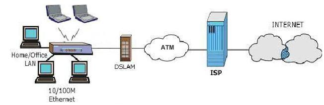
9 5), RFC 1483 encapsulation over ATM, MAC encapsulated routing (ENET Encapsulation) as well as PPP over Ethernet (RFC 2516). Network Management Embedded Web Configurator CLI (Command Line Interpreter) SNMP manageable DHCP Server/Client Built-in Diagnostic Tools Syslog TFTP/FTP server, firmware upgrade and configuration backup/support supported Diagnostics Capabilities The BIPAC-5100/5100W can perform self-diagnostic tests. These tests check the integrity of the following circuitry: - FLASH memory - ADSL circuitry - RAM - LAN port Filters The BIPAC-5100/5100W's packet filtering functions allows added network security and management. Ease of Installation The BIPAC-5100/5100W is designed for quick, intuitive and easy installation. Housing The BIPAC-5100/5100W's all new compact and ventilated housing minimizes space requirements making it easy to position anywhere in your busy office. 1.3 Applications for the BIPAC-5100/5100W The BIPAC-5100/5100W is the ideal high-speed Internet access solution. The BIPAC-5100/5100W supports the TCP/IP protocol, which the Internet uses exclusively. It is compatible with all major ADSL DSLAM (Digital Subscriber Line Access Multiplexer) providers. A DSLAM is a rack of ADSL line cards with data multiplexed into a backbone network interface/connection (for example, T1, OC3, DS3, ATM or Frame Relay). Think of it as the equivalent of a modem rack for ADSL. In addition, for BIPAC-5100/5100W, you can insert an optional wireless PCMICA card into the BIPAC-5100/5100W and allow wireless stations access to your network resources. A typical Internet access application is shown below. 9
10 10
11 Chapter 2 Introducing the Web Configurator b is only supported for the BIPAC-5100W This chapter describes how to access and navigate the web configurator. 2.1 Web Configurator Overview The embedded web configurator allows you to manage the BIPAC-5100/5100W from anywhere through a browser such as Microsoft Internet Explorer or Netscape Navigator. Use Internet Explorer 6.0 and later or Netscape Navigator 7.0 and later versions with JavaScript enabled. It is recommended that you set your screen resolution to 1024 by 768 pixels 2.2 Accessing the BIPAC-5100/5100W Web Configurator Step 1. Make sure your BIPAC-5100/5100W hardware is properly connected (refer to the Compact Guide or Read Me First). Step 2. Prepare your computer/computer network to connect to the BIPAC-5100/5100W (refer to the Compact Guide or Read Me First). Step 3. Launch your web browser. Step 4. Type " " as the URL. Step 5. An Enter Network Password window displays. Enter the user name ( admin is the default), password ( admin is the default) and click OK. 11


12 Step 6. You should now see the Site Map screen. 2.3 Navigating the BIPAC-5100/5100W Web Configurator The following summarizes how to navigate the web configurator from the Site Map screen. Screens vary slightly for different BIPAC-5100/5100W models. Click Wizard Setup to begin a series of screens to configure the BIPAC-5100/5100W for the first time. Click a link under Advanced Setup to configure advanced BIPAC-5100/5100W features. Click a link under Maintenance to see BIPAC-5100/5100W performance statistics, upload firmware and back up, restore or upload a configuration file. Click SITE MAP to go to the Site Map screen. Click Logout in the navigation panel when you have finished a BIPAC-5100/5100W management session. 12
13 2.4 Configuring Password It is highly recommended that you change the password for accessing the BIPAC-5100/5100W. To change the BIPAC-5100/5100W s password, click Advanced Setup and then Password. The screen appears as shown. The following table describes the labels in this screen. LABEL Old Password DESCRIPTION Type the default password or the existing password you use to access the system in this field. New Password Retype to Confirm Apply Cancel Type the new password in this field. Type the new password again in this field. Click Apply to save your changes back to the BIPAC-5100/5100W. Click Cancel to begin configuring this screen afresh. 2.5 Resetting the BIPAC-5100/5100W If you forget your password or cannot access the BIPAC-5100/5100W, you will need to reload the factory-default configuration file or use the RESET button the back of the BIPAC-5100/5100W. Uploading this configuration file replaces the current configuration file with the factory-default configuration file. This means that you will lose all configurations that you had previously and the speed of the console port will be reset to the default of 9600bps with 8 data bit, no parity, one stop bit and flow control set to none. The password will be reset to admin, also. 13

14 2.5.1 Using The Reset Button Step 1. Make sure the SYS LED is on (not blinking). Step 2. Press the RESET button for five seconds, and then release it. When the SYS LED begins to blink, the defaults have been restored and the BIPAC-5100/5100W restarts Uploading a Configuration File Via Console Port Download the default configuration file from the Billion FTP site, unzip it and save it in a folder. Step 1. Turn off the BIPAC-5100/5100W, begin a terminal emulation software session and turn on the BIPAC-5100/5100W again. When you see the message "Press Any key to enter Debug Mode within 3 seconds", press any key to enter debug mode. Step 2. Enter "atlc" after "Enter Debug Mode" message. Step 3. Wait for "Starting XMODEM upload" message before activating Xmodem upload on your terminal. This is an example Xmodem configuration upload using HyperTerminal. Step 4. Click Transfer, then Send File to display the following screen. Step 5. After successful firmware upload, enter "atgo" to restart the router. 14
15 Chapter 3 Wizard Setup b is only supported for the BIPAC-5100W This chapter provides information on the Wizard Setup screens in the web configurator. 3.1 Wizard Setup Introduction Use the Wizard Setup screens to configure your system for Internet access settings and fill in the fields with the information in the Internet Account Information table of the Compact Guide or Read Me First. Your ISP may have already configured some of the fields in the wizard screens for you. 3.2 Encapsulation Be sure to use the encapsulation method required by your ISP. The BIPAC-5100/5100W supports the following methods ENET ENCAP The MAC Encapsulated Routing Link Protocol (ENET ENCAP) is only implemented with the IP network protocol. IP packets are routed between the Ethernet interface and the WAN interface and then formatted so that they can be understood in a bridged environment. For instance, it encapsulates routed Ethernet frames into bridged ATM cells. ENET ENCAP requires that you specify a gateway IP address in the Ethernet Encapsulation Gateway field in the second wizard screen. You can get this information from your ISP PPP over Ethernet PPPoE provides access control and billing functionality in a manner similar to dial-up services using PPP. The BIPAC-5100/5100W bridges a PPP session over Ethernet (PPP over Ethernet, RFC 2516) from your computer to an ATM PVC (Permanent Virtual Circuit) which connects to ADSL Access Concentrator where the PPP session terminates. One PVC can support any number of PPP sessions from your LAN. For more information on PPPoE, see the appendix PPPoA PPPoA stands for Point to Point Protocol over ATM Adaptation Layer 5 (AAL5). It provides 15
16 access control and billing functionality in a manner similar to dial-up services using PPP. The BIPAC-5100/5100W encapsulates the PPP session based on RFC1483 and sends it through an ATM PVC (Permanent Virtual Circuit) to the Internet Service Provider's (ISP) DSLAM (digital access multiplexer). Please refer to RFC 2364 for more information on PPPoA. Refer to RFC 1661 for more information on PPP RFC 1483 RFC 1483 describes two methods for Multiprotocol Encapsulation over ATM Adaptation Layer 5 (AAL5). The first method allows multiplexing of multiple protocols over a single ATM virtual circuit (LLC-based multiplexing) and the second method assumes that each protocol is carried over a separate ATM virtual circuit (VC-based multiplexing). Please refer to the RFC for more detailed information. 3.3 Multiplexing There are two conventions to identify what protocols the virtual circuit (VC) is carrying. Be sure to use the multiplexing method required by your ISP VC-based Multiplexing In this case, by prior mutual agreement, each protocol is assigned to a specific virtual circuit; for example, VC1 carries IP, etc. VC-based multiplexing may be dominant in environments where dynamic creation of large numbers of ATM VCs is fast and economical LLC-based Multiplexing In this case one VC carries multiple protocols with protocol identifying information being contained in each packet header. Despite the extra bandwidth and processing overhead, this method may be advantageous if it is not practical to have a separate VC for each carried protocol, for example, if charging heavily depends on the number of simultaneous VCs. 3.4 VPI and VCI Be sure to use the correct Virtual Path Identifier (VPI) and Virtual Channel Identifier (VCI) numbers assigned to you. The valid range for the VPI is 0 to 255 and for the VCI is 32 to (0 to 31 is reserved for local management of ATM traffic). Please see the appendix for more information. 3.5 Wizard Setup Configuration: First Screen In the SITE MAP screen click Wizard Setup to display the first wizard screen. 16
17 The following table describes the labels in this screen. LABEL DESCRIPTION Mode From the Mode drop-down list box, select Routing (default) if your ISP allows multiple computers to share an Internet account. Otherwise select Bridge. Encapsulation Select the encapsulation type your ISP uses from the Encapsulation drop-down list box. Choices vary depending on what you select in the Mode field. If you select Bridge in the Mode field, select either PPPoA or RFC If you select Routing in the Mode field, select PPPoA, RFC 1483, ENET ENCAP or PPPoE. Multiplex Select the multiplexing method used by your ISP from the Multiplex drop-down list box either VC-based or LLC-based. Virtual Circuit ID VPI (Virtual Path Identifier) and VCI (Virtual Channel Identifier) define a virtual circuit. Refer to VPI VCI Next Enter the VPI assigned to you. This field may already be configured. Enter the VCI assigned to you. This field may already be configured. Click this button to go to the next wizard screen. The next wizard screen you see depends on what protocol you chose above. Click on the protocol link to see the next wizard screen for that protocol. 3.6 IP Address and Subnet Mask Similar to the way houses on a street share a common street name, so too do computers on a LAN share one common network number. 17
18 Where you obtain your network number depends on your particular situation. If the ISP or your network administrator assigns you a block of registered IP addresses, follow their instructions in selecting the IP addresses and the subnet mask. If the ISP did not explicitly give you an IP network number, then most likely you have a single user account and the ISP will assign you a dynamic IP address when the connection is established. If this is the case, it is recommended that you select a network number from to and you must enable the Network Address Translation (NAT) feature of the BIPAC-5100/5100W. The Internet Assigned Number Authority (IANA) reserved this block of addresses specifically for private use; please do not use any other number unless you are told otherwise. Let's say you select as the network number; which covers 254 individual addresses, from to (zero and 255 are reserved). In other words, the first three numbers specify the network number while the last number identifies an individual computer on that network. Once you have decided on the network number, pick an IP address that is easy to remember, for instance, , for your BIPAC-5100/5100W, but make sure that no other device on your network is using that IP address. The subnet mask specifies the network number portion of an IP address. Your BIPAC-5100/5100W will compute the subnet mask automatically based on the IP address that you entered. You don't need to change the subnet mask computed by the BIPAC-5100/5100W unless you are instructed to do otherwise. 3.7 IP Address Assignment A static IP is a fixed IP that your ISP gives you. A dynamic IP is not fixed; the ISP assigns you a different one each time. The Single User Account feature can be enabled or disabled if you have either a dynamic or static IP. However the encapsulation method assigned influences your choices for IP address and ENET ENCAP Gateway IP Assignment with PPPoA or PPPoE Encapsulation If you have a dynamic IP, then the IP Address and ENET ENCAP Gateway fields are not applicable (N/A). If you have a static IP, then you only need to fill in the IP Address field and not the ENET ENCAP Gateway field IP Assignment with RFC 1483 Encapsulation In this case the IP Address Assignment must be static with the same requirements for the IP Address and ENET ENCAP Gateway fields as stated above IP Assignment with ENET ENCAP Encapsulation In this case you can have either a static or dynamic IP. For a static IP you must fill in all the IP Address and ENET ENCAP Gateway fields as supplied by your ISP. However for a dynamic IP, the BIPAC-5100/5100W acts as a DHCP client on the WAN port and so the IP Address and 18
19 ENET ENCAP Gateway fields are not applicable (N/A) as the DHCP server assigns them to the BIPAC-5100/5100W Private IP Addresses Every machine on the Internet must have a unique address. If your networks are isolated from the Internet, for example, only between your two branch offices, you can assign any IP addresses to the hosts without problems. However, the Internet Assigned Numbers Authority (IANA) has reserved the following three blocks of IP addresses specifically for private networks: You can obtain your IP address from the IANA, from an ISP or it can be assigned from a private network. If you belong to a small organization and your Internet access is through an ISP, the ISP can provide you with the Internet addresses for your local networks. On the other hand, if you are part of a much larger organization, you should consult your network administrator for the appropriate IP addresses. 3.8 Nailed-Up Connection (PPP) A nailed-up connection is a dial-up line where the connection is always up regardless of traffic demand. The BIPAC-5100/5100W does two things when you specify a nailed-up connection. The first is that idle timeout is disabled. The second is that the BIPAC-5100/5100W will try to bring up the connection when turned on and whenever the connection is down. A nailed-up connection can be very expensive for obvious reasons. Do not specify a nailed-up connection unless your telephone company offers flat-rate service or you need a constant connection and the cost is of no concern 3.9 NAT NAT (Network Address Translation - NAT, RFC 1631) is the translation of the IP address of a host in a packet, for example, the source address of an outgoing packet, used within one network to a different IP address known within another network Wizard Setup Configuration: Second Screen The second wizard screen varies depending on what mode and encapsulation type you use. All screens shown are with routing mode. Configure the fields and click Next to continue. 19
20 PPPoE Select PPPoE from the Encapsulation drop-down list box in the first wizard screen to display the screen as shown. The following table describes the labels in this screen. LABEL Service Name User Name DESCRIPTION Type the name of your PPPoE service here. Configure User Name and Password fields for PPPoA and PPPoE encapsulation only. Enter the user name exactly as your ISP assigned. If assigned a name in the form user@domain where domain identifies a service name, then enter both components exactly as given. Password IP Address Enter the password associated with the user name above. A static IP address is a fixed IP that your ISP gives you. A dynamic IP address is not fixed; the ISP assigns you a different one each time you connect to the Internet. The Single User Account feature can be used with either a dynamic or static IP address. Select Obtain an IP Address Automatically if you have a dynamic IP address; otherwise select Static IP Address and type your ISP assigned IP address in the IP Address text box below. Connection Select Connect on Demand when you don't want the connection up all the time and specify an idle time-out (in seconds) in the Max. Idle Timeout field. The default setting selects Connection on Demand with 0 as the idle time-out, which means the Internet session will Select Nailed-Up Connection when you want your connection up all the time. The BIPAC-5100/5100W will try to bring up the connection automatically if it is disconnected. 20
21 Network Address Translation Back Select None, SUA Only or Full Feature from the drop-sown list box. Refer to the NAT chapter for more details. Click Back to go back to the first wizard screen. Next Click Next to continue to the next wizard screen RFC 1483 Select RFC 1483 from the Encapsulation drop-down list box in the first wizard screen to display the screen as shown. The following table describes the labels in this screen. LABEL IP Address DESCRIPTION This field is available if you select Routing in the Mode field. Type your ISP assigned IP address in this field. Network Address Translation Network Address Translation LABEL Back Select None, SUA Only or Full Feature from the drop-sown list box. Refer to the NAT chapter for more details. Select None, SUA Only or Full Feature from the drop-sown list box. Refer to the NAT chapter for more details. DESCRIPTION Click Back to go back to the first wizard screen. Next Click Next to continue to the next wizard screen ENET ENCAP Select ENET ENCAP from the Encapsulation drop-down list box in the first wizard screen to display the screen as shown. 21
22 The following table describes the labels in this screen. LABEL IP Address DESCRIPTION A static IP address is a fixed IP that your ISP gives you. A dynamic IP address is not fixed; the ISP assigns you a different one each time you connect to the Internet. The Single User Account feature can be used with either a dynamic or static IP address. Select Obtain an IP Address Automatically if you have a dynamic IP address; otherwise select Static IP Address and type your ISP assigned IP address in the IP Address text box below. Subnet Mask Enter a subnet mask in dotted decimal notation. Refer to the IP Subnetting appendix to calculate a subnet mask If you are implementing subnetting. ENET ENCAP Gateway Network Address Translation Back You must specify a gateway IP address (supplied by your ISP) when you use ENET ENCAP in the Encapsulation field in the previous screen. Select None, SUA Only or Full Feature from the drop-sown list box. Refer to the NAT chapter for more details. Click Back to go back to the first wizard screen. Next Click Next to continue to the next wizard screen PPPoA Select PPPoA from the Encapsulation drop-down list box in the first wizard screen to display the screen as shown. 22
23 The following table describes the labels in this screen. LABEL User Name DESCRIPTION Enter the user name exactly as your ISP assigned. If assigned a name in the form user@domain where domain identifies a service name, then enter both components exactly as given. Password IP Address Enter the password associated with the user name above. This option is available if you select Routing in the Mode field. A static IP address is a fixed IP that your ISP gives you. A dynamic IP address is not fixed; the ISP assigns you a different one each time you connect to the Internet. The Single User Account feature can be used with either a dynamic or static IP address. Click Obtain an IP Address Automatically if you have a dynamic IP address; otherwise click Static IP Address and type your ISP assigned IP address in the IP Address text box below Connection Select Connect on Demand when you don't want the connection up all the time and specify an idle time-out (in seconds) in the Max. Idle Timeout field. The default setting selects Connection on Demand with 0 as the idle time-out, which means the Internet session will not timeout Select Nailed-Up Connection when you want your connection up all the time. The BIPAC-5100/5100W will try to bring up the connection automatically if it is disconnected. 23
24 Network Address Translation This option is available if you select Routing in the Mode field. Select None, SUA Only or Full Feature from the drop-sown list box. Refer to the NAT chapter for more details. Back Next Click Back to go back to the first wizard screen. Click Next to continue to the next wizard screen DHCP Setup DHCP (Dynamic Host Configuration Protocol, RFC 2131 and RFC 2132) allows individual clients to obtain TCP/IP configuration at start-up from a server. You can configure the BIPAC-5100/5100W as a DHCP server or disable it. When configured as a server, the BIPAC-5100/5100W provides the TCP/IP configuration for the clients. If you turn DHCP service off, you must have another DHCP server on your LAN, or else the computer must be manually configured IP Pool Setup The BIPAC-5100/5100W is pre-configured with a pool of 100 IP addresses starting from to for the client machines Wizard Setup Configuration: Third Screen Verify the settings in the screen shown next. To change the LAN information on the BIPAC-5100/5100W, click Change LAN Configurations. Otherwise click Save Settings to save the configuration and skip to section
25 If you want to change your BIPAC-5100/5100W LAN settings, click Change LAN Configuration to display the screen as shown next. The following table describes the labels in this screen. LABEL DESCRIPTION 25
26 LAN IP Address Enter the IP address of your BIPAC-5100/5100W in dotted decimal notation, for example, (factory default). LAN Subnet Mask Enter a subnet mask in dotted decimal notation. DHCP DHCP Server From the DHCP Server drop-down list box, select On to allow your BIPAC-5100/5100W to assign IP addresses, an IP default gateway and DNS servers to computer systems that support the DHCP client. Select Off to disable DHCP server. When DHCP server is used, set the following items: Client IP Pool This field specifies the first of the contiguous addresses in the IP address pool. Starting Address Size of Client IP This field specifies the size or count of the IP address pool. Pool Primary DNS Server Secondary DNS Enter the IP addresses of the DNS servers. The DNS servers are passed to the DHCP clients along with the IP address and the subnet mask. As above. Server Back Finish Click Back to go back to the first wizard screen. Click Finish to save the settings and proceed to the next wizard screen Wizard Setup Configuration: Connection Tests The BIPAC-5100/5100W automatically tests the connection to the computer(s) connected to the LAN ports. To test the connection from the BIPAC-5100/5100W to the ISP, click Start Diagnose. Otherwise click Return to Main Menu to go back to the Site Map screen. 26
27 3.14 Test Your Internet Connection Launch your web browser and navigate to Internet access is just the beginning. Refer to the rest of this User s Guide for more detailed information on the complete range of BIPAC-5100/5100W features. If you cannot access the Internet, open the web configurator again to confirm that the Internet settings you configured in the Wizard Setup are correct. 27
28 Chapter 4 LAN Setup b is only supported for the BIPAC-5100W This chapter describes how to configure LAN settings. 4.1 LAN Overview A Local Area Network (LAN) is a shared communication system to which many computers are attached. A LAN is a computer network limited to the immediate area, usually the same building or floor of a building. The LAN screens can help you configure a LAN DHCP server and manage IP addresses LANs, WANs and the BIPAC-5100/5100W The actual physical connection determines whether the BIPAC-5100/5100W ports are LAN or WAN ports. There are two separate IP networks, one inside, the LAN network; the other outside: the WAN network as shown next: 4.2 DNS Server Address DNS (Domain Name System) is for mapping a domain name to its corresponding IP address 28
29 and vice versa, for example, the IP address of is The DNS server is extremely important because without it, you must know the IP address of a machine before you can access it. The DNS server addresses that you enter in the DHCP setup are passed to the client machines along with the assigned IP address and subnet mask. There are two ways that an ISP disseminates the DNS server addresses. The first is for an ISP to tell a customer the DNS server addresses, usually in the form of an information sheet, when s/he signs up. If your ISP gives you the DNS server addresses, enter them in the DNS Server fields in DHCP Setup, otherwise, leave them blank. Some ISP s choose to pass the DNS servers using the DNS server extensions of PPP IPCP (IP Control Protocol) after the connection is up. If your ISP did not give you explicit DNS servers, chances are the DNS servers are conveyed through IPCP negotiation. The BIPAC-5100/5100W supports the IPCP DNS server extensions through the DNS proxy feature. If the Primary and Secondary DNS Server fields in DHCP Setup are not specified, for instance, left as , the BIPAC-5100/5100W tells the DHCP clients that it itself is the DNS server. When a computer sends a DNS query to the BIPAC-5100/5100W, the BIPAC-5100/5100W forwards the query to the real DNS server learned through IPCP and relays the response back to the computer. Please note that DNS proxy works only when the ISP uses the IPCP DNS server extensions. It does not mean you can leave the DNS servers out of the DHCP setup under all circumstances. If your ISP gives you explicit DNS servers, make sure that you enter their IP addresses in the DHCP Setup menu. This way, the BIPAC-5100/5100W can pass the DNS servers to the computers and the computers can query the DNS server directly without the BIPAC-5100/5100W s intervention. 4.3 DNS Server Address Assignment Use DNS (Domain Name System) to map a domain name to its corresponding IP address and vice versa. The DNS server is extremely important because without it, you must know the IP address of a computer before you can access it. There are two ways that an ISP disseminates the DNS server addresses. 1. The ISP tells you the DNS server addresses, usually in the form of an information sheet, when you sign up. If your ISP gives you DNS server addresses, enter them in the DNS Server fields in DHCP Setup. 2. Leave the DNS Server fields in DHCP Setup blank (for example ). The BIPAC-5100/5100W acts as a DNS proxy when this field is blank. 29
30 4.4 LAN TCP/IP The BIPAC-5100/5100W has built-in DHCP server capability that assigns IP addresses and DNS servers to systems that support DHCP client capability Factory LAN Defaults The LAN parameters of the BIPAC-5100/5100W are preset in the factory with the following values: IP address of with subnet mask of (24 bits) DHCP server enabled with 100 client IP addresses starting from These parameters should work for the majority of installations. If your ISP gives you explicit DNS server address(es), read the embedded web configurator help regarding what fields need to be configured IP Address and Subnet Mask Refer to the IP Address and Subnet Mask section in the Wizard Setup chapter for this information RIP Setup RIP (Routing Information Protocol) allows a router to exchange routing information with other routers. The RIP Direction field controls the sending and receiving of RIP packets. When set to: 1. Both - the BIPAC-5100/5100W will broadcast its routing table periodically and incorporate the RIP information that it receives. 2. In Only - the BIPAC-5100/5100W will not send any RIP packets but will accept all RIP packets received. 3. Out Only - the BIPAC-5100/5100W will send out RIP packets but will not accept any RIP packets received. 4. None - the BIPAC-5100/5100W will not send any RIP packets and will ignore any RIP packets received. The Version field controls the format and the broadcasting method of the RIP packets that the BIPAC-5100/5100W sends (it recognizes both formats when receiving). RIP-1 is universally supported; but RIP-2 carries more information. RIP-1 is probably adequate for most networks, unless you have an unusual network topology. Both RIP-2B and RIP-2M sends the routing data in RIP-2 format; the difference being that RIP-2B uses subnet broadcasting while RIP-2M uses multicasting Multicast Traditionally, IP packets are transmitted in one of either two ways - Unicast (1 sender - 1 recipient) or Broadcast (1 sender - everybody on the network). Multicast delivers IP packets to a group of hosts on the network - not everybody and not just 1. 30
31 IGMP (Internet Group Multicast Protocol) is a network-layer protocol used to establish membership in a Multicast group - it is not used to carry user data. IGMP version 2 (RFC 2236) is an improvement over version 1 (RFC 1112) but IGMP version 1 is still in wide use. If you would like to read more detailed information about interoperability between IGMP version 2 and version 1, please see sections 4 and 5 of RFC The class D IP address is used to identify host groups and can be in the range to The address is not assigned to any group and is used by IP multicast computers. The address is used for query messages and is assigned to the permanent group of all IP hosts (including gateways). All hosts must join the group in order to participate in IGMP. The address is assigned to the multicast routers group. The BIPAC-5100/5100W supports both IGMP version 1 (IGMP-v1) and IGMP version 2 (IGMP-v2). At start up, the BIPAC-5100/5100W queries all directly connected networks to gather group membership. After that, the BIPAC-5100/5100W periodically updates this information. IP multicasting can be enabled/disabled on the BIPAC-5100/5100W LAN and/or WAN interfaces in the web configurator (LAN; WAN). Select None to disable IP multicasting on these interfaces. 4.5 Configuring LAN Click LAN to open the following screen. The following table describes the labels in this screen. 31
32 DHCP LABEL DESCRIPTION If set to Server, your BIPAC-5100/5100W can assign IP addresses, an IP default gateway and DNS servers to Windows 95, Windows NT and other systems that support the DHCP client. If set to None, the DHCP server will be disabled. If set to Relay, the BIPAC-5100/5100W acts as a surrogate DHCP server and relays DHCP requests and responses between the remote server and the clients. Enter the IP address of the actual, remote DHCP server in the Remote DHCP Server field in this case. When DHCP is used, the following items need to be set: LAN Subnet Mask Enter a subnet mask in dotted decimal notation. Client IP Pool This field specifies the first of the contiguous addresses in the IP address pool. Starting Address Size of Client IP This field specifies the size or count of the IP address pool. Pool Primary DNS Server Secondary DNS Enter the IP addresses of the DNS servers. The DNS servers are passed to the DHCP clients along with the IP address and the subnet mask. As above. Server Remote DHCP Server If Relay is selected in the DHCP field above then enter the IP address of the actual remote DHCP server here. TCP/IP IP Address Enter the IP address of your BIPAC-5100/5100W in dotted decimal notation, for example, (factory default). IP Subnet Mask RIP Direction RIP Version Multicast Type the subnet mask assigned to you by your ISP (if given). Select the RIP direction from None, Both, In Only and Out Only. Select the RIP version from RIP-1, RIP-2B and RIP-2M. IGMP (Internet Group Multicast Protocol) is a session-layer protocol used to establish membership in a multicast group. The BIPAC-5100/5100W supports both IGMP version 1 (IGMP-v1) and IGMP-v2. Select None to disable it. Apply Cancel Click this button to save these settings back to the BIPAC-5100/5100W. Click this button to reset the fields in this screen. 32
33 Chapter 5 Wireless LAN Setup b is only supported for the BIPAC-5100W This chapter discusses how to configure Wireless LAN on the BIPAC-5100/5100W. 5.1 Wireless LAN Overview This section introduces the wireless LAN and some basic configurations. Wireless LANs can be as simple as two computers with wireless LAN cards communicating in a peer-to-peer network or as complex as a number of computers with wireless LAN cards communicating through access points which bridge network traffic to the wired LAN Channel The range of radio frequencies used by IEEE b wireless devices is called a channel. Channels available depend on your geographical area. You may have a choice of channels (for your region) so you should use a different channel than an adjacent AP (access point) to reduce interference. Interference occurs when radio signals from different access points overlap causing interference and degrading performance. Adjacent channels partially overlap however. To avoid interference due to overlap, your AP should be on a channel at least five channels away from a channel that an adjacent AP is using. For example, if your region has 11 channels and an adjacent AP is using channel 1, then you need to select a channel between 6 or ESS ID An Extended Service Set (ESS) is a group of access points or wireless gateways connected to a wired LAN on the same subnet. An ESS ID uniquely identifies each set. All access points or wireless gateways and their associated wireless stations in the same set must have the same ESSID RTS/CTS A hidden node occurs when two stations are within range of the same access point, but are not within range of each other. The following figure illustrates a hidden node. Both stations (STA) are within range of the access point (AP) or wireless gateway, but out-of-range of each other, so they cannot hear each other, that is they do not know if the channel is currently being used. 33
34 Therefore, they are considered hidden from each other. When station A sends data to the BIPAC-5100/5100W, it might not know that the station B is already using the channel. If these two stations send data at the same time, collisions may occur when both sets of data arrive at the AP at the same time, resulting in a loss of messages for both stations. RTS/CTS is designed to prevent collisions due to hidden nodes. An RTS/CTS defines the biggest size data frame you can send before an RTS (Request To Send)/CTS (Clear to Send) handshake is invoked. When a data frame exceeds the RTS/CTS value you set (between 0 to 2432 bytes), the station that wants to transmit this frame must first send an RTS (Request To Send) message to the AP for permission to send it. The AP then responds with a CTS (Clear to Send) message to all other stations within its range to notify them to defer their transmission. It also reserves and confirms with the requesting station the time frame for the requested transmission. Stations can send frames smaller than the specified RTS/CTS directly to the AP without the RTS (Request To Send)/CTS (Clear to Send) handshake. You should only configure RTS/CTS if the possibility of hidden nodes exists on your network and the cost of resending large frames is more than the extra network overhead involved in the RTS (Request To Send)/CTS (Clear to Send) handshake. If the RTS/CTS value is greater than the Fragmentation Threshold value (see next), then the RTS (Request To Send)/CTS (Clear to Send) handshake will never occur as data frames will be fragmented before they reach RTS/CTS size Fragmentation Threshold A Fragmentation Threshold is the maximum data fragment size (between 256 and 2432 bytes) that can be sent in the wireless network before the BIPAC-5100/5100W will fragment the packet into smaller data frames. A large Fragmentation Threshold is recommended for networks not prone to interference while you should set a smaller threshold for busy networks or networks that are prone to interference. If the Fragmentation Threshold value is smaller than the RTS/CTS value (see previously) you set then the RTS (Request To Send)/CTS (Clear to Send) handshake will never occur as data frames will be fragmented before they reach RTS/CTS size. 34
35 5.2 Levels of Security Wireless security is vital to your network to protect wireless communication between wireless stations, access points and the wired network. The figure below shows the possible wireless security levels on your BIPAC-5100/5100W. The highest security level relies on EAP (Extensible Authentication Protocol) for authentication and utilizes dynamic WEP key exchange. It requires interaction with a RADIUS (Remote Authentication Dial-In User Service) server either on the WAN or your LAN to provide authentication service for wireless stations. If you do not enable any wireless security on your BIPAC-5100/5100W, your network is accessible to any wireless networking device that is within range. Use the BIPAC-5100/5100W web configurator to configurator to set up your wireless LAN security settings. Refer to the chapter on using the BIPAC-5100/5100W web configurator to see how to access the web configurator. 5.3 Data Encryption with WEP WEP encryption scrambles the data transmitted between the wireless stations and the access points to keep network communications private. It encrypts unicast and multicast communications in a network. Both the wireless stations and the access points must use the same WEP key for data encryption and decryption. Your BIPAC-5100/5100W allows you to configure up to four 64-bit or 128-bit WEP keys but only one key can be enabled at any one time. 5.4 Configuring Wireless LAN Click Wireless LAN, Wireless to open the Wireless screen. 35
36 The following table describes the labels in this screen. ESSID LABEL DESCRIPTION The ESSID (Extended Service Set Identification) is a unique name to identify the BIPAC-5100/5100W in the wireless LAN. Wireless stations associating to the BIPAC-5100/5100W must have the same ESSID. Enter a descriptive name (up to 32 characters). Hide ESSID Select Yes to hide the ESSID in so a station cannot obtain the ESSID through passive scanning. Select No to make the ESSID visible so a station can obtain the ESSID through passive scanning. Channel ID The range of radio frequencies used by IEEE b wireless devices is called a channel. Select a channel from the drop-down list box. RTS/CTS Threshold The RTS (Request To Send) threshold (number of bytes) for enabling RTS/CTS handshake. Data with its frame size larger than this value will perform the RTS/CTS handshake. Setting this attribute to be larger than the maximum MSDU (MAC service data unit) size turns off the RTS/CTS handshake. Setting this attribute to zero turns on the RTS/CTS handshake. Enter a value between 0 and Fragmentation The threshold (number of bytes) for the fragmentation boundary for directed 36
37 Threshold messages. It is the maximum data fragment size that can be sent. Enter a value between 256 and WEP Encryption WEP (Wired Equivalent Privacy) encrypts data frames before transmitting over the wireless network. Select Disable to allow all wireless computers to communicate with the access points without any data encryption. Select 64-bit WEP or 128-bit WEP to use data encryption. Key 1 to Key 4 The WEP keys are used to encrypt data. Both the BIPAC-5100/5100W and the wireless stations must use the same WEP key for data transmission. If you chose 64-bit WEP, then enter any 5 ASCII characters or 10 hexadecimal characters ("0-9", "A-F"). If you chose 128-bit WEP, then enter 13 ASCII characters or 26 hexadecimal characters ("0-9", "A-F"). You must configure all four keys, but only one key can be activated at any one time. The default key is key 1. IP Address Enter the IP address of your BIPAC-5100/5100W in dotted decimal notation, for example, (factory default). IP Subnet Mask RIP Direction RIP Version Multicast Type the subnet mask assigned to you by your ISP (if given). Select the RIP direction from None, Both, In Only and Out Only. Select the RIP version from RIP-1, RIP-2B and RIP-2M. IGMP (Internet Group Multicast Protocol) is a session-layer protocol used to establish membership in a multicast group. The BIPAC-5100/5100W supports both IGMP version 1 (IGMP-v1) and IGMP-v2. Select None to disable it. Back Apply Cancel Click Back to go to the main wireless LAN setup screen. Click Apply to save your changes back to the BIPAC-5100/5100W. Click Cancel to begin configuring this screen afresh. 5.5 Configuring MAC Filter The MAC filter screen allows you to configure the BIPAC-5100/5100W to give exclusive access to up to 32 devices (Allow Association) or exclude up to 32 devices from accessing the BIPAC-5100/5100W (Deny Association). Every Ethernet device has a unique MAC (Media Access Control) address. The MAC address is assigned at the factory and consists of six pairs of hexadecimal characters, for example, 00:AA:BB:00:00:02. You need to know the MAC address of the devices to configure this screen. To change your BIPAC-5100/5100W s MAC filter settings, click Wireless LAN, MAC Filter to open the MAC Filter screen. The screen appears as shown. 37
38 The following table describes the labels in this menu. LABEL DESCRIPTION Active Action Select Yes from the drop down list box to enable MAC address filtering. Define the filter action for the list of MAC addresses in the MAC address filter table. Select Deny Association to block access to the router, MAC addresses not listed will be allowed to access the router. Select Allow Association to permit access to the router, MAC addresses not listed will be denied access to the router. MAC Address Enter the MAC addresses (in XX:XX:XX:XX:XX:XX format) of the wireless station that are allowed or denied access to the BIPAC-5100/5100W in these address fields. Back Apply Cancel Click Back to go to the main wireless LAN setup screen. Click Apply to save your changes back to the BIPAC-5100/5100W. Click Cancel to begin configuring this screen afresh. 38
39 Chapter 6 WAN Setup b is only supported for the BIPAC-5100W This chapter describes how to configure WAN settings. 6.1 WAN Overview A WAN (Wide Area Network) is an outside connection to another network or the Internet. See the Wizard Setup chapter for more information on the fields in the WAN screens. 6.2 PPPoE Encapsulation The BIPAC-5100/5100W supports PPPoE (Point-to-Point Protocol over Ethernet). PPPoE is an IETF Draft standard (RFC 2516) specifying how a personal computer (PC) interacts with a broadband modem (DSL, cable, wireless, etc.) connection. The PPPoE option is for a dial-up connection using PPPoE. For the service provider, PPPoE offers an access and authentication method that works with existing access control systems (for example Radius). PPPoE provides a login and authentication method that the existing Microsoft Dial-Up Networking software can activate, and therefore requires no new learning or procedures for Windows users. One of the benefits of PPPoE is the ability to let you access one of multiple network services, a function known as dynamic service selection. This enables the service provider to easily create and offer new IP services for individuals. Operationally, PPPoE saves significant effort for both you and the ISP or carrier, as it requires no specific configuration of the broadband modem at the customer site. By implementing PPPoE directly on the BIPAC-5100/5100W (rather than individual computers), the computers on the LAN do not need PPPoE software installed, since the BIPAC-5100/5100W does that part of the task. Furthermore, with NAT, all of the LANs computers will have access. 39
40 6.3 PPTP Encapsulation Point-to-Point Tunneling Protocol (PPTP) is a network protocol that enables secure transfer of data from a remote client to a private server, creating a Virtual Private Network (VPN) using TCP/IP-based networks. PPTP supports on-demand, multi-protocol and virtual private networking over public networks, such as the Internet. 6.4 Traffic Shaping Traffic Shaping is an agreement between the carrier and the subscriber to regulate the average rate and burstiness or fluctuation of data transmission over an ATM network. This agreement helps eliminate congestion, which is important for transmission of real time data such as audio and video connections. Peak Cell Rate (PCR) is the maximum rate at which the sender can send cells. This parameter may be lower (but not higher) than the maximum line speed. 1 ATM cell is 53 bytes (424 bits), so a maximum speed of 1 Mbps gives a maximum PCR of 2415 cells/sec. This rate is not guaranteed because it is dependent on the line speed. Sustained Cell Rate (SCR) is the mean cell rate of a bursty, on-off traffic source that can be sent at the peak rate, and a parameter for burst-type traffic. SCR may not be greater than the PCR; the system default is 0 cells/sec. Maximum Burst Size (MBS) is the maximum number of cells that can be sent at the PCR. After MBS is reached, cell rates fall below SCR until cell rate averages to the SCR again. At this time, more cells (up to the MBS) can be sent at the PCR again. The following figure illustrates the relationship between PCR, SCR and MBS. 40

41 6.5 Configuring WAN Setup To change your BIPAC-5100/5100W s WAN remote node settings, click WAN. The screen differs by the encapsulation PPP Half Bridge When the PPP Half Bridge is enabled the BIPAC-5100/5100W becomes invisible. The DHCP server will duplicate the WAN IP address from the ISP to the local client PC. Only one PC is able to access the Internet using half bridge mode. Half bridge mode can only be used when a single IP address has been assigned by the ISP, it is not suitable for services that provide multiple IP addresses. Half bridge mode is used when the use of NAT or NAPT is not desired and there is a single computer attached to the BIPAC-5100/5100W ADSL Gateway When to use Half Bridge mode When using a separate firewall that will be protecting the network, half bridge mode will allow the firewall to appear on the internet using the publicly accessible IP address assigned by the ISP. This configuration will allow the dedicated firewall to have full control of the inbound and outbound traffic and is the intended purpose for this mode. Some applications that embed the IP address of the computer in the data are not compatible with NAT or NAPT and so the computer requires a real public IP address. However the number of applications that are not compatible with NAT/NAPT are reducing as developers address the 41
42 issues. Before deciding to use half bridge mode please check to see if the application can be made to work using the virtual server port forwarding feature on the BIPAC-5100/5100W. Using NAT/NAPT is preferable as it provides the first line of defence against attack from hackers/crackers and allows the connection of more than one computer. The following table describes the labels in this screen. LABEL DESCRIPTION 42
43 Name Enter the name of your Internet Service Provider, e.g., MyISP. This information is for identification purposes only. Mode Select Routing (default) from the drop-down list box if your ISP allows multiple computers to share an Internet account. Otherwise select Bridge. Encapsulation Select the method of encapsulation used by your ISP from the drop-down list box. Choices vary depending on the mode you select in the Mode field. If you select Bridge in the Mode field, select either PPPoA or RFC If you select Routing in the Mode field, select PPPoA, RFC 1483, ENET ENCAP or PPPoE. Multiplex Select the method of multiplexing used by your ISP from the drop-down list. Choices are VC or LLC. Virtual Circuit ID VPI (Virtual Path Identifier) and VCI (Virtual Channel Identifier) define a virtual circuit. Refer to the appendix for more information. VPI The valid range for the VPI is 0 to 255. Enter the VPI assigned to you. VCI The valid range for the VCI is 32 to (0 to 31 is reserved for local management of ATM traffic). Enter the VCI assigned to you. ATM QoS Type Select CBR (Continuous Bit Rate) to specify fixed (always-on) bandwidth for voice or data traffic. Select UBR (Unspecified Bit Rate) for applications that are non-time sensitive, such as . Select VBR (Variable Bit Rate) for bursty traffic and bandwidth sharing with other applications. VBR is not available on all models. Cell Rate Cell rate configuration often helps eliminate traffic congestion that slows transmission of real time data such as audio and video connections. Peak Cell Rate Divide the DSL line rate (bps) by 424 (the size of an ATM cell) to find the Peak Cell Rate (PCR). This is the maximum rate at which the sender can send cells. Type the PCR here. Sustain Cell Rate The Sustain Cell Rate (SCR) sets the average cell rate (long-term) that can be transmitted. Type the SCR, which must be less than the PCR. Maximum Burst Maximum Burst Size (MBS) refers to the maximum number of cells that can be sent at Size the peak rate. Type the MBS, which is less than Login Information (PPPoA and PPPoE encapsulation only) Service Name (PPPoE only) Type the name of your PPPoE service here. User Name Enter the user name exactly as your ISP assigned. If assigned a name in the form user@domain where domain identifies a service name, then enter both components exactly as given. Password A static IP address is a fixed IP that your ISP gives you. A dynamic IP address is not fixed; the ISP assigns you a different one each time you connect to the Internet. The Single User Account feature can be used with either a dynamic or static IP address. 43
44 Select Obtain an IP Address Automatically if you have a dynamic IP address; otherwise select Static IP Address and type your ISP assigned IP address in the IP Address field below. Connection The schedule rule(s) have priority over your Connection settings. (PPPoA and PPPoE encapsulation only) Nailed-Up Select Nailed-Up Connection when you want your connection up all the time. The Connection BIPAC-5100/5100W will try to bring up the connection automatically if it is disconnected. Connect on Select Connect on Demand when you don't want the connection up all the time and Demand specify an idle time-out in the Max Idle Timeout field. Max Idle Timeout Specify an idle time-out in the Max Idle Timeout field when you select Connect on Demand. The default setting is 0, which means the Internet session will not timeout. Subnet Mask (ENET ENCAP encapsulation only) ENET ENCAP Gateway (ENET Enter a subnet mask in dotted decimal notation. Refer to the Subnetting appendix in the to calculate a subnet mask If you are implementing subnetting. You must specify a gateway IP address (supplied by your ISP) when you select ENET ENCAP in the Encapsulation field. ENCAP encapsulation only) TCP MSS Option (PPPoA/PPPoE, Routing mode only) This will increase the current MSS limit to the number specified, hence the tweak test will report Max Packet Size as the specified number plus 40*. The catch is that every time your PPPoE disconnects and re-connects it will revert back to MSS limit of 1400 (Max packet size of 1440) and needs to be entered after PPPoE connects again. This function does not work before PPPoE connects. *Referring to RFC879, the MSS value = MTU - 40, so by limiting the MSS value, you will get limited MTU value. Back Apply Cancel Click Back to return to the previous screen. Click Apply to save the changes. Click Cancel to begin configuring this screen afresh. 44
45 Chapter 7 Network Address Translation (NAT) b is only supported for the BIPAC-5100W This chapter discusses how to configure NAT on the BIPAC-5100/5100W. 7.1 NAT Overview NAT (Network Address Translation - NAT, RFC 1631) is the translation of the IP address of a host in a packet, for example, the source address of an outgoing packet, used within one network to a different IP address known within another network NAT Definitions Inside/outside denotes where a host is located relative to the BIPAC-5100/5100W, for example, the computers of your subscribers are the inside hosts, while the web servers on the Internet are the outside hosts. Global/local denotes the IP address of a host in a packet as the packet traverses a router, for example, the local address refers to the IP address of a host when the packet is in the local network, while the global address refers to the IP address of the host when the same packet is traveling in the WAN side. Note that inside/outside refers to the location of a host, while global/local refers to the IP address of a host used in a packet. Thus, an inside local address (ILA) is the IP address of an inside host in a packet when the packet is still in the local network, while an inside global address (IGA) is the IP address of the same inside host when the packet is on the WAN side. The following table summarizes this information. ITEM DESCRIPTION Inside Outside Local This refers to the host on the LAN. This refers to the host on the WAN. This refers to the packet address (source or destination) as the packet travels on the LAN. Global This refers to the packet address (source or destination) as the packet travels on the 45
46 WAN What NAT Does In the simplest form, NAT changes the source IP address in a packet received from a subscriber (the inside local address) to another (the inside global address) before forwarding the packet to the WAN side. When the response comes back, NAT translates the destination address (the inside global address) back to the inside local address before forwarding it to the original inside host. Note that the IP address (either local or global) of an outside host is never changed. The global IP addresses for the inside hosts can be either static or dynamically assigned by the ISP. In addition, you can designate servers, for example, a web server and a telnet server, on your local network and make them accessible to the outside world. With no servers defined, your BIPAC-5100/5100W filters out all incoming inquiries, thus preventing intruders from probing your network. For more information on IP address translation, refer to RFC 1631, The IP Network Address Translator (NAT) How NAT Works Each packet has two addresses a source address and a destination address. For outgoing packets, the ILA (Inside Local Address) is the source address on the LAN, and the IGA (Inside Global Address) is the source address on the WAN. For incoming packets, the ILA is the destination address on the LAN, and the IGA is the destination address on the WAN. NAT maps private (local) IP addresses to globally unique ones required for communication with hosts on other networks. It replaces the original IP source address (and TCP or UDP source port numbers for Many-to-One and Many-to-Many Overload NAT mapping) in each packet and then forwards it to the Internet. The BIPAC-5100/5100W keeps track of the original addresses and port numbers so incoming reply packets can have their original values restored. The following figure illustrates this. 46
47 7.1.4 NAT Application The following figure illustrates a possible NAT application, where three inside LANs (logical LANs using IP Alias) behind the BIPAC-5100/5100W can communicate with three distinct WAN networks. More examples follow at the end of this chapter NAT Mapping Types NAT supports five types of IP/port mapping. They are: 1. One to One: In One-to-One mode, the BIPAC-5100/5100W maps one local IP address to one global IP address. 2. Many to One: In Many-to-One mode, the BIPAC-5100/5100W maps multiple local IP addresses to one global IP address. This is equivalent to SUA (for instance, PAT, port address translation), Billion s Single User Account feature that previous Billion routers supported (the SUA Only option in today s routers). 3. Many to Many Overload: In Many-to-Many Overload mode, the BIPAC-5100/5100W maps the multiple local IP addresses to shared global IP addresses. 4. Many-to-Many No Overload: In Many-to-Many No Overload mode, the BIPAC-5100/5100W maps each local IP address to a unique global IP address. 5. Server: This type allows you to specify inside servers of different services behind the NAT to be accessible to the outside world. The following table summarizes these types. TYPE IP MAPPING One-to-One ILA1 IGA1 Many-to-One (SUA/PAT) ILA1 IGA1 ILA2 IGA1 Many-to-Many Overload ILA1 IGA1 47
48 ILA2 ILA3 IGA2 IGA1 ILA4 IGA2 Many-to-Many No Overload ILA1 IGA1 ILA2 ILA3 IGA2 IGA3 Server Server 1 IP IGA1 Server 2 IP Server 3 IP IGA1 IGA1 7.2 SUA (Single User Account) Versus NAT SUA (Single User Account) is a implementation of a subset of NAT that supports two types of mapping, Many-to-One and Server. The BIPAC-5100/5100W also supports Full Feature NAT to map multiple global IP addresses to multiple private LAN IP addresses of clients or servers using mapping types as outlined in 7.3 SUA Server A SUA server set is a list of inside (behind NAT on the LAN) servers, for example, web or FTP, that you can make visible to the outside world even though SUA makes your whole inside network appear as a single computer to the outside world. You may enter a single port number or a range of port numbers to be forwarded, and the local IP address of the desired server. The port number identifies a service; for example, web service is on port 80 and FTP on port 21. In some cases, such as for unknown services or where one server can support more than one service (for example both FTP and web service), it might be better to specify a range of port numbers. You can allocate a server IP address that corresponds to a port or a range of ports. Many residential broadband ISP accounts do not allow you to run any server processes (such as a Web or FTP server) from your location. Your ISP may periodically check for servers and may suspend your account if it discovers any active services at your location. If you are unsure, refer to your ISP. Default Server IP Address In addition to the servers for specified services, NAT supports a default server IP address. A default server receives packets from ports that are not specified in this screen. 48
49 7.3.1 Port Forwarding: Services and Port Numbers A NAT server set is a list of inside (behind NAT on the LAN) servers, for example, web or FTP, that you can make accessible to the outside world even though NAT makes your whole inside network appear as a single machine to the outside world. Use the SUA Server page to forward incoming service requests to the server(s) on your local network. You may enter a single port number or a range of port numbers to be forwarded, and the local IP address of the desired server. The port number identifies a service; for example, web service is on port 80 and FTP on port 21. In some cases, such as for unknown services or where one server can support more than one service (for example both FTP and web service), it might be better to specify a range of port numbers. In addition to the servers for specified services, NAT supports a default server. A service request that does not have a server explicitly designated for it is forwarded to the default server. If the default is not defined, the service request is simply discarded. The most often used port numbers are shown in the following table. Please refer to RFC 1700 for further information about port numbers. SERVICES PORT NUMBER ECHO 7 FTP (File Transfer Protocol) 21 SMTP (Simple Mail Transfer Protocol) 25 DNS (Domain Name System) 53 Finger 79 HTTP (Hyper Text Transfer protocol or WWW, Web) 80 POP3 (Post Office Protocol) 110 NNTP (Network News Transport Protocol) 119 SNMP (Simple Network Management Protocol) 161 SNMP trap 162 PPTP (Point-to-Point Tunneling Protocol) Configuring Servers Behind SUA (Example) Let's say you want to assign ports to one server, port 80 to another and assign a default server IP address of as shown in the next figure. 49

50 7.4 Selecting the NAT Mode Click NAT to open the following screen. The following table describes the labels in this screen. LABEL DESCRIPTION None SUA Only Select this radio button to disable NAT. Select this radio button if you have just one public WAN IP address for your BIPAC-5100/5100W. The BIPAC-5100/5100W uses Address Mapping Set 1 in the NAT - Edit SUA/NAT Server Set screen. Edit Details Full Feature Click this link to go to the NAT - Edit SUA/NAT Server Set screen. Select this radio button if you have multiple public WAN IP addresses for your BIPAC-5100/5100W. Edit Details Apply Click this link to go to the NAT - Address Mapping Rules screen. Click Apply to save your configuration. 7.5 Configuring SUA Server Click NAT, Select SUA Only and click Edit Details to open the following screen. 50

51 The following table describes the labels in this screen. LABEL DESCRIPTION Start Port No. Enter a port number in this field. To forward only one port, enter the port number again in the End Port No. field. To forward a series of ports, enter the start port number here and the end port number in the End Port No. field. End Port No. Enter a port number in this field. To forward only one port, enter the port number again in the Start Port No. field above and then enter it again in this field. To forward a series of ports, enter the last port number in a series that begins with the port number in the Start Port No. field above. IP Address Save Cancel Enter your server IP address in this field. Click Save to save your changes back to the BIPAC-5100/5100W. Click Cancel to return to the previous configuration. 7.6 Configuring Address Mapping Ordering your rules is important because the BIPAC-5100/5100W applies the rules in the order 51

52 that you specify. When a rule matches the current packet, the BIPAC-5100/5100W takes the corresponding action and the remaining rules are ignored. If there are any empty rules before your new configured rule, your configured rule will be pushed up by that number of empty rules. For example, if you have already configured rules 1 to 6 in your current set and now you configure rule number 9. In the set summary screen, the new rule will be rule 7, not 9. Now if you delete rule 4, rules 5 to 7 will be pushed up by 1 rule, so old rules 5, 6 and 7 become new rules 4, 5 and 6. To change your BIPAC-5100/5100W s address mapping settings, click NAT, Select Full Feature and click Edit Details to open the following screen. The following table describes the labels in this screen. LABEL Local Start IP DESCRIPTION This is the starting Inside Local IP Address (ILA). Local IP addresses are N/A for Server port mapping. Local End IP This is the end Inside Local IP Address (ILA). If your rule is for all local IP addresses, then enter as the Local Start IP address and as the Local End IP address. This field is N/A for One-to-one and Server mapping types. Global Start IP This is the starting Inside Global IP Address (IGA). Enter here if you have a dynamic IP address from your ISP. You can only do this for Many-to-One and Server mapping types. Global End IP This is the ending Inside Global IP Address (IGA). This field is N/A for One-to-one, Many-to-One and Server mapping types. Type 1-1: One-to-one mode maps one local IP address to one global IP address. Note that port numbers do not change for the One-to-one NAT mapping type. M-1: Many-to-One mode maps multiple local IP addresses to one global IP address. 52
53 This is equivalent to SUA (i.e., PAT, port address translation), Billion's Single User Account feature that previous Billion routers supported only. M-M Ov (Overload): Many-to-Many Overload mode maps multiple local IP addresses to shared global IP addresses. MM No (No Overload): Many-to-Many No Overload mode maps each local IP address to unique global IP addresses. Server: This type allows you to specify inside servers of different services behind the NAT to be accessible to the outside world. Back Click Back to return to the NAT Mode screen. 7.7 Editing an Address Mapping Rule To edit an address mapping rule, click the rule s link in the NAT Address Mapping Rules screen to display the screen shown next. The following table describes the labels in this screen. LABEL DESCRIPTION Type Choose the port mapping type from one of the following. 1. One-to-One: One-to-One mode maps one local IP address to one global IP address. Note that port numbers do not change for One-to-one NAT mapping type. 2. Many-to-One: Many-to-One mode maps multiple local IP addresses to one global IP address. This is equivalent to SUA (i.e., PAT, port address translation), Billion's Single User Account feature that previous Billion routers supported only. 3. Many-to-Many Overload: Many-to-Many Overload mode maps multiple local IP addresses to shared global IP addresses. 4. Many-to-Many No Overload: Many-to-Many No Overload mode maps each 53
54 local IP address to unique global IP addresses. 5. Server: This type allows you to specify inside servers of different services behind the NAT to be accessible to the outside world. Local Start IP This is the starting Inside Local IP Address (ILA). Local IP addresses are N/A for Server port mapping. Local End IP This is the end Inside Local IP Address (ILA). If your rule is for all local IP addresses, then enter as the Local Start IP address and as the Local End IP address. This field is N/A for One-to-one and Server mapping types. Global Start IP This is the starting Inside Global IP Address (IGA). Enter here if you have a dynamic IP address from your ISP. Global End IP This is the ending Inside Global IP Address (IGA). This field is N/A for One-to-one, Many-to-One and Server mapping types. Server Mapping Set Only available when Type is set to Server. Select a number from 1 to 10 from the drop-down menu to choose a server set from the NAT - Address Mapping Rules screen. Edit Details Click this link to go to the NAT - Edit SUA/NAT Server Set screen to edit a server set that you have selected in the Server Mapping Set field. Apply Cancel Delete Click Apply to save your changes back to the BIPAC-5100/5100W. Click Cancel to return to the previously saved settings. Click Delete to exit this screen without saving 54
55 Chapter 8 Dynamic DNS Setup b is only supported for the BIPAC-5100W This chapter discusses how to configure your BIPAC-5100/5100W to use Dynamic DNS. 8.1 Dynamic DNS Dynamic DNS allows you to update your current dynamic IP address with one or many dynamic DNS services so that anyone can contact you (in NetMeeting, CU-SeeMe, etc.). You can also access your FTP server or Web site on your own computer using a DNS-like address (for instance myhost.dhs.org, where myhost is a name of your choice) that will never change instead of using an IP address that changes each time you reconnect. Your friends or relatives will always be able to call you even if they don't know your IP address. First of all, you need to have registered a dynamic DNS account with This is for people with a dynamic IP from their ISP or DHCP server that would still like to have a DNS name. The Dynamic DNS service provider will give you a password or key DYNDNS Wildcard Enabling the wildcard feature for your host causes *.yourhost.dyndns.org to be aliased to the same IP address as yourhost.dyndns.org. This feature is useful if you want to be able to use, for example, and still reach your hostname. 8.2 Configuring Dynamic DNS To change your BIPAC-5100/5100W s DDNS, click Dynamic DNS. The screen appears as shown. 55
56 The following table describes the labels in this screen. LABEL DESCRIPTION Active Service Provider Host Name Select this check box to use dynamic DNS. Select the name of your Dynamic DNS service provider. Type the domain name assigned to your BIPAC-5100/5100W by your Dynamic DNS provider. Address User Password Enable Wildcard Apply Cancel Type your address. Type your user name. Type the password assigned to you. Select this check box to enable DYNDNS Wildcard. Click Apply to save your changes back to the BIPAC-5100/5100W. Click Cancel to return to the previously saved settings. 56
57 Chapter 9 Time and Date Setup b is only supported for the BIPAC-5100W Use this screen to configure the BIPAC-5100/5100W s time and date settings. This chapter is not available on all models. 9.1 Configuring Time Zone To change your BIPAC-5100/5100W s time and date, click Time Zone. The screen appears as shown. Use this screen to configure the BIPAC-5100/5100W s time based on your local time zone. 57
58 The following table describes the labels in this screen. LABEL DESCRIPTION Time Server Use Time Server Select the time service protocol that your time server sends when you turn on the when Bootup BIPAC-5100/5100W. Not all time servers support all protocols, so you may have to check with your ISP/network administrator or use trial and error to find a protocol that works. The main difference between them is the format. Daytime (RFC 867) format is day/month/year/time zone of the server. Time (RFC 868) format displays a 4-byte integer giving the total number of seconds since 1970/1/1 at 0:0:0. The default, NTP (RFC 1305), is similar to Time (RFC 868). Select None to enter the time and date manually. Time Server IP Enter the IP address of your time server. Check with your ISP/network Address administrator if you are unsure of this information. Time Zone Choose the time zone of your location. This will set the time difference between your time zone and Greenwich Mean Time (GMT). Daylight Savings Select this option if you use daylight savings time. Daylight saving is a period from late spring to early fall when many countries set their clocks ahead of normal local time by one hour to give more daytime light in the evening. Start Date Enter the month and day that your daylight-savings time starts on if you selected Daylight Savings. End Date Enter the month and day that your daylight-savings time ends on if you selected Daylight Savings. Calibrate system Click this button to have your BIPAC-5100/5100W use the time server (that you clock with Time configured above) to set its internal system clock. Server now Please wait for up to 60 seconds while the BIPAC-5100/5100W locates the time server. If the BIPAC-5100/5100W cannot find the time server, please check the time server protocol and its IP address. If the IP address was entered correctly, try pinging it for example to test the connection. Date Current Date This field displays the date of your BIPAC-5100/5100W. Each time you reload this page, the BIPAC-5100/5100W synchronizes the time with the time server. New Date This field displays the last updated date from the time server. (yyyy-mm-dd) When you select None in the Use Time Server when Bootup field, enter the new date in this field and then click Apply. Time 58
59 Current Time This field displays the time of your BIPAC-5100/5100W. Each time you reload this page, the BIPAC-5100/5100W synchronizes the time with the time server. New Time This field displays the last updated time from the time server. When you select None in the Use Time Server when Bootup field, enter the new time in this field and then click Apply. Apply Cancel Click Apply to save your changes back to the BIPAC-5100/5100W. Click Cancel to return to the previously saved settings. 59
60 Chapter 10 Remote Management Configuration b is only supported for the BIPAC-5100W This chapter provides information on configuring remote management. Remote management is not available on all models 10.1 Remote Management Overview Remote management allows you to determine which services/protocols can access which BIPAC-5100/5100W interface (if any) from which computers. You may manage your BIPAC-5100/5100W from a remote location via: Internet (WAN only) LAN only ALL (LAN and WAN) Neither (Disable) To disable remote management of a service, select Disable in the corresponding Server Access field Remote Management Limitations Remote management over LAN or WAN will not work when: 1. A filter is applied to block a Telnet, FTP or Web service. 2. You have disabled that service in one of the remote management screens. 3. The IP address in the Secured Client IP field does not match the client IP address. If it does not 4. There is an console session running. 5. There is already another remote management session of the same type (web, FTP or Telnet) running. You may only have one remote management session of the same type running at one time. 6. There is a web remote management session running with a Telnet session. A Telnet session will be disconnected if you begin a web session; it will not begin if there already is a web session Remote Management and NAT When NAT is enabled: Use the BIPAC-5100/5100W s WAN IP address when configuring from the WAN. 60
61 Use the BIPAC-5100/5100W s LAN IP address when configuring from the LAN System Timeout There is a system timeout of five minutes (three hundred seconds) for either the console port or telnet/web/ftp connections. Your BIPAC-5100/5100W automatically logs you out if you do nothing in this timeout period, except when sys stdio has been changed on the command line Telnet You can configure your BIPAC-5100/5100W for remote Telnet access as shown next FTP You can upload and download BIPAC-5100/5100W firmware and configuration files using FTP. To use this feature, your computer must have an FTP client Web You can use the BIPAC-5100/5100W s embedded web configurator for configuration and file management. See the online help for details Configuring Remote Management Click Remote Management to open the following screen. 61

62 The following table describes the labels in this screen. LABEL Server Type DESCRIPTION Each of these labels denotes a service that you may use to remotely manage the BIPAC-5100/5100W. Access Status Port Select the access interface. Choices are All, LAN Only, WAN Only and Disable. This field shows the port number for the remote management service. You may change the port number for a service in this field, but you must use the same port umber to use that service for remote management. Secured Client IP The default allows any client to use this service to remotely manage the BIPAC-5100/5100W. Type an IP address to restrict access to a client with a matching IP address. Apply Cancel Click Apply to save your settings back to the BIPAC-5100/5100W. Click Cancel to begin configuring this screen afresh. 62
63 Chapter 11 Universal Plug-and-Play (UPnP) b is only supported for the BIPAC-5100W This chapter introduces the UPnP feature in the web configurator Universal Plug and Play Overview Universal Plug and Play (UPnP) is a distributed, open networking standard that uses TCP/IP for simple peer-to-peer network connectivity between devices. An UPnP device can dynamically join a network, obtain an IP address, convey its capabilities and learn about other devices on the network. In turn, a device can leave a network smoothly and automatically when it is no longer in use How do I know if I'm using UPnP? UPnP hardware is identified as an icon in the Network Connections folder (Windows XP). Each UPnP compatible device installed on your network will appear as a separate icon. Selecting the icon of a UPnP device will allow you to access the information and properties of that device NAT Traversal UPnP NAT traversal automates the process of allowing an application to operate through NAT. UPnP network devices can automatically configure network addressing, announce their presence in the network to other UPnP devices and enable exchange of simple product and service descriptions. NAT traversal allows the following: Dynamic port mapping Learning public IP addresses Assigning lease times to mappings Windows Messenger is an example of an application that supports NAT traversal and UPnP. See the Network Address Translation (NAT) chapter for further information about NAT Cautions with UPnP The automated nature of NAT traversal applications in establishing their own services may 63
64 present network security issues. Network information and configuration may also be obtained and modified by users in some network environments. All UPnP-enabled devices may communicate freely with each other without additional configuration. Disable UPnP if this is not your intention. UPnP broadcasts are only allowed on the LAN. See later sections for examples of installing UPnP in Windows XP and Windows Me as well as an example of using UPnP in Windows Configuring UPnP From the Site Map in the main menu, click UPnP under Advanced Setup to display the screen shown next. The following table describes the labels in this screen. LABEL Enable the Universal Plug and Play (UPnP) Service DESCRIPTION Select this checkbox to activate UPnP. Be aware that anyone could use a UPnP application to open the web configurator's login screen without entering the BIPAC-5100/5100W's IP address (although you must still enter the password to access the web configurator). Allow users to make Select this check box to allow UPnP-enabled applications to automatically configuration changes configure the BIPAC-5100/5100W so that they can communicate through the through UPnP BIPAC-5100/5100W, for example by using NAT traversal, UPnP applications automatically reserve a NAT forwarding port in order to communicate with another UPnP enabled device; this eliminates the need to manually configure port forwarding for the UPnP enabled application. Apply Cancel Click Apply to save your settings back to the BIPAC-5100/5100W. Click Cancel to return to the previously saved settings Installing UPnP in Windows Example This section shows how to install UPnP in Windows Me and Windows XP. 64


65 Installing UPnP in Windows Me Follow the steps below to install the UPnP in Windows Me. Step 1. Click Start and Control Panel. Double-click Add/Remove Programs. Step 2. Click on the Windows Setup tab and select Communication in the Components selection box. Click Details. Step 3. In the Communications window, select the Universal Plug and Play check box in the Components selection box. Step 4. Click OK to go back to the Add/Remove Programs Properties window and click Next. Step 5. Restart the computer when prompted Installing UPnP in Windows XP Follow the steps below to install the UPnP in Windows XP. Step 1. Click Start and Control Panel. Step 2. Double-click Network Connections. Step 3. In the Network Connections window, click Advanced in the main menu and select Optional Networking Components. 65


66 The Windows Optional Networking Components Wizard window displays. Step 4. Select Networking Service in the Components selection box and click Details. Step 5. In the Networking Services window, select the Universal Plug and Play check box. Step 6. Click OK to go back to the Windows Optional Networking Component Wizard window and click Next. 66


67 11.4 Using UPnP in Windows XP Example This section shows you how to use the UPnP feature in Windows XP. You must already have UPnP installed in Windows XP and UPnP activated on the BIPAC-5100/5100W. Make sure the computer is connected to a LAN port of the BIPAC-5100/5100W. Turn on your computer and the BIPAC-5100/5100W Auto-discover Your UPnP-enabled Network Device Step 1. Click start and Control Panel. Double-click Network Connections. An icon displays under Internet Gateway. Step 2. Right-click the icon and select Properties. Step 3. In the Internet Connection Properties window, click Settings to see the port mappings there were automatically created. Step 4. You may edit or delete the port mappings or click Add to manually add port mappings. 67


68 Step 5. Select Show icon in notification area when connected option and click OK. An icon displays in the system tray Step 6. Double-click on the icon to display your current Internet connection status Web Configurator Easy Access With UPnP, you can access the web-based configurator on the BIPAC-5100/5100W without finding out the IP address of the BIPAC-5100/5100W first. This comes helpful if you do not know the IP address of the BIPAC-5100/5100W. Follow the steps below to access the web configurator. Step 1. Click Start and then Control Panel. Step 2. Double-click Network Connections. Step 3. Select My Network Places under Other Places. 68

69 Step 4. An icon with the description for each UPnP-enabled device displays under Local Network. Step 5. Right-click on the icon for your BIPAC-5100/5100W and select Invoke. The web configurator login screen displays. Step 6. Right-click on the icon for your BIPAC-5100/5100W and select Properties. A properties window displays with basic information about the BIPAC-5100/5100W. 69
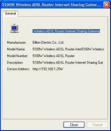
70 70
71 Chapter12 Maintenance b is only supported for the BIPAC-5100W This chapter displays system information such as Billion firmware, port IP addresses and port traffic statistics Maintenance Overview Use the maintenance screens to view system information, upload new firmware, manage configuration and restart your BIPAC-5100/5100W System Status Screen Click System Status, where you can use to monitor your BIPAC-5100/5100W. Note that these fields are READ-ONLY and are meant to be used for diagnostic purposes. 71

72 The following table describes the labels in this screen. LABEL DESCRIPTION System Status System Name This is the name of your BIPAC-5100/5100W. It is for identification purposes. RAS F/W Version This is the firmware version and the date created. DSL FW Version This is the DSL firmware version associated with your BIPAC-5100/5100W. Standard This is the standard that your BIPAC-5100/5100W is using. WAN Information IP Address This is the WAN port IP address. 72

73 IP Subnet Mask This is the WAN port IP subnet mask. Default Gateway This is the IP address of the default gateway, if applicable. VPI/VCI This is the Virtual Path Identifier and Virtual Channel Identifier that you entered in the first Wizard screen. LAN Information MAC Address This is the MAC (Media Access Control) or Ethernet address unique to your BIPAC-5100/5100W. IP Address This is the LAN port IP address. IP Subnet Mask This is the LAN port IP subnet mask. DHCP This is the WAN port DHCP role - Server, Relay (not all BIPAC-5100/5100W models) or None. DHCP Start IP This is the first of the contiguous addresses in the IP address pool. DHCP Pool Size This is the number of IP addresses in the IP address pool. Show Statistics Click Show Statistics to see router performance statistics such as number of System Statistics packets sent and number of packets received for each port. Click Show Statistics in the System Status screen to open the following screen. Read-only information here includes port status and packet specific statistics. Also provided are "system up time" and "poll interval(s)". The Poll Interval(s) field is configurable. 73
74 The following table describes the labels in this screen. LABEL System up Time CPU Load WAN Port Statistics Link Status Transfer Rate Upstream Speed Downstream Speed Node-Link DESCRIPTION This is the elapsed time the system has been up. This field specifies the percentage of CPU utilization. This is the WAN port. This is the status of your WAN link. This is the transfer rate in kbps. This is the upstream speed of your BIPAC-5100/5100W. This is the downstream speed of your BIPAC-5100/5100W. This field displays the remote node index number and link type. Link types are PPPoA, ENET, RFC 1483 and PPPoE. LAN Port Statistics Interface Status This is the LAN port. This field displays the type of port. For the WAN port, this displays the port speed and duplex setting if you're using Ethernet encapsulation and down (line is down), idle (line (ppp) idle), dial (starting to trigger a call) and drop (dropping a call) if you're using PPPoE encapsulation. For a LAN port, this shows the port speed and duplex setting. TxPkts RxPkts Errors Tx B/s Rx B/s Up Time Collisions Poll Interval(s) Set Interval This field displays the number of packets transmitted on this port. This field displays the number of packets received on this port. This field displays the number of error packets on this port. This field displays the number of bytes transmitted in the last second. This field displays the number of bytes received in the last second. This field displays the elapsed time this port has been up. This is the number of collisions on this port. Type the time interval for the browser to refresh system statistics. Click this button to apply the new poll interval you entered in the Poll Interval field above. Stop Click this button to halt the refreshing of the system statistics DHCP Table Screen DHCP (Dynamic Host Configuration Protocol, RFC 2131 and RFC 2132) allows individual clients to obtain TCP/IP configuration at start-up from a server. You can configure the BIPAC-5100/5100W as a DHCP server or disable it. When configured as a server, the BIPAC-5100/5100W provides the TCP/IP configuration for the clients. If set to None, DHCP service will be disabled and you must have another DHCP server on your LAN, or else the computer must be manually configured. Click MAINTENANCE, and then the DHCP Table tab. Read-only information here relates to 74


75 your DHCP status. The DHCP table shows current DHCP client information (including IP Address, Host Name and MAC Address) of all network clients using the DHCP server. The following table describes the labels in this screen. LABEL Host Name IP Address MAC Address DESCRIPTION This is the name of the host computer. This field displays the IP address relative to the Host Name field. This field displays the MAC (Media Access Control) address of the computer with the displayed host name. Every Ethernet device has a unique MAC address. The MAC address is assigned at the factory and consists of six pairs of hexadecimal characters, for example, 00:AA:BB:00:00: Wireless Screens These read-only screens display information about the BIPAC-5100/5100W s wireless LAN Association List This screen displays the MAC address(es) of the wireless clients that are currently logged in to the network. Click Wireless LAN and then Association List to open the screen shown next. The following table describes the labels in this screen. LABEL DESCRIPTION # This is the index number of an associated wireless client. 75
Prestige 660HW Series. Prestige 660H Series. Quick Start Guide
 Prestige 660HW Series ADSL 2+ 4-Port Gateway with 802.11g Wireless Prestige 660H Series ADSL 2+ 4-Port Gateway Quick Start Guide Version 3.40 01/2005 Table of Contents Introducing the Prestige... 3 1 Hardware
Content 1 OVERVIEW HARDWARE DESCRIPTION HARDWARE INSTALLATION PC CONFIGURATION GUIDE... 5 WEB-BASED MANAGEMENT GUIDE...
 Content 1 OVERVIEW...1 1.1FEATURES...1 1.2 PACKETCONTENTS...3 1.3 SYSTEM REQUIREMENTS... 1.4 FACTORY DEFAULTS...4 1.5 WARNINGS AND CAUTIONS...4 2 HARDWARE DESCRIPTION... 6 3 HARDWARE INSTALLATION...8 4
ADSL User Manual. Wireless-N BROADBAND ROUTER : Introduction
 ADSL User Manual 1 : Introduction The ADSL is a communication terminal, which integrates ADSL access, broadband SOHO router, WLAN and VoIP service. This device can provide high data transmission, downstream
IP806GA/GB Wireless ADSL Router
 IP806GA/GB Wireless ADSL Router 802.11g/802.11b Wireless Access Point ADSL Modem NAT Router 4-Port Switching Hub User's Guide Table of Contents CHAPTER 1 INTRODUCTION... 1 Wireless ADSL Router Features...
LevelOne. User Manual. 11g Wireless ADSL2+ Modem Router WBR Ver. 1.0
 LevelOne User Manual WBR-3601 11g Wireless ADSL2+ Modem Router Ver. 1.0 Table of Contents Product Overview... 3 Product Description... 3 Specification... 4 LED Meaning... 6 Back Panel Connectors... 7 Factory
FOUR-PORT ADSL ROUTER. KD319RI ADSL Router User Manual
 FOUR-PORT ADSL ROUTER KD319RI ADSL Router User Manual NOTICE This document contains proprietary information protected by copyright, and this Manual and all the accompanying hardware, software, and documentation
Horizons Model 1500WR Wireless 4-Port Router Quick Start Guide. REVISION: 1 VERSION: a DATE: March
 Horizons Model 1500WR Wireless 4-Port Router Quick Start Guide REVISION: 1 VERSION: 030904a DATE: March 2004 www.direct2data.com 2 Congratulations on your purchase of the ParkerVision 1500WR Wireless Router.
FOUR-PORT ADSL ROUTER. KD319EUI ADSL Router User Manual
 FOUR-PORT KD319EUI ADSL Router User Manual NOTICE This document contains proprietary information protected by copyright, and this Manual and all the accompanying hardware, software, and documentation are
FOUR-PORT ADSL ROUTER. KD319MUI ADSL Router User Manual
 FOUR-PORT ADSL ROUTER KD319MUI ADSL Router User Manual NOTICE This document contains proprietary information protected by copyright, and this Manual and all the accompanying hardware, software, and documentation
NBG-416N. Wireless N-lite Home Router. Default Login Details. IMPORTANT! READ CAREFULLY BEFORE USE.
 NBG-416N Wireless N-lite Home Router IMPORTANT! Default Login Details LAN IP https://192.168.1.1 Address User Name admin Password 1234 READ CAREFULLY BEFORE USE. KEEP THIS GUIDE FOR FUTURE REFERENCE. IMPORTANT!
BIPAC 5102 Series. (802.11g) ADSL2+ Modem/Router. User s Manual
 ADSL2+ Modem/Router. User s Manual") BIPAC 5102 Series (802.11g) ADSL2+ Modem/Router User s Manual Chapter 1... 1 1.1 Introducing the BIPAC 5102 Series... 1 1.2 Features of the BIPAC 5102 Series... 3 1.3 Applications for the BIPAC 5102 Series...
BIPAC 5102 Series (802.11g) ADSL2+ Modem/Router User s Manual Chapter 1... 1 1.1 Introducing the BIPAC 5102 Series... 1 1.2 Features of the BIPAC 5102 Series... 3 1.3 Applications for the BIPAC 5102 Series...
CHAPTER 7 ADVANCED ADMINISTRATION PC
 ii Table of Contents CHAPTER 1 INTRODUCTION... 1 Broadband ADSL Router Features... 1 Package Contents... 3 Physical Details... 4 CHAPTER 2 INSTALLATION... 6 Requirements... 6 Procedure... 6 CHAPTER 3 SETUP...
LevelOne FBR User s Manual. 1W, 4L 10/100 Mbps ADSL Router. Ver
 LevelOne FBR-1416 1W, 4L 10/100 Mbps ADSL Router User s Manual Ver 1.00-0510 Table of Contents CHAPTER 1 INTRODUCTION... 1 FBR-1416 Features... 1 Package Contents... 3 Physical Details... 3 CHAPTER 2
OV504R6. Quick Start Guide
 OV504R6 Quick Start Guide 1 Overview The router is a highly ADSL2/2+ Integrated Access Device and can support ADSL link with downstream up to 24 Mbps and upstream up to 1 Mbps. It is designed to provide
LevelOne WBR User s Manual. 11g Wireless ADSL VPN Router. Ver
 LevelOne WBR-3407 11g Wireless ADSL VPN Router User s Manual Ver 1.00-0510 Table of Contents CHAPTER 1 INTRODUCTION... 1 Wireless ADSL Router Features... 1 Package Contents... 5 Physical Details... 6 CHAPTER
802.11g Wireless Four Port Ethernet ADSL2+ Router. User s Manual
 802.11g Wireless Four Port Ethernet ADSL2+ Router User s Manual June 2006 Copyright Copyright 2006 by this company. All rights reserved. No part of this publication may be reproduced, transmitted, transcribed,
SOHOSpeed ADSL Ethernet/Wireless Gateway User s Manual
 SOHOSpeed ADSL Ethernet/Wireless Gateway User s Manual Revision 1.0 July 2004 SOHOSpeed ADSL Ethernet/Wireless Gateway User s Manual Table of Contents 1. INTRODUCTION...4 1.1 FEATURES...4 2. GATEWAY OVERVIEW...5
DVA-G3340S High-Speed 2.4 GHz Wireless ADSL VOIP Router. Manual
 DVA-G3340S High-Speed 2.4 GHz Wireless ADSL VOIP Router Manual Contents Package Contents...4 Introduction...5 Features...8 Using the Web Interface...9 Home > Wizard...9 Home > Wireless...10 Home > Wireless
User Manual. WLAN ADSL2+ Router
 User Manual WLAN ADSL2+ Router INDEX 1.0 About This Manual... 1 1.1 Document Objectives... 1 1.2 Product Overview... 1 1.3 Product Description... 1 2.0 Specification... 2 2.1 LED Meaning... 3 2.2 Back
Wireless-G Router User s Guide
 Wireless-G Router User s Guide 1 Table of Contents Chapter 1: Introduction Installing Your Router System Requirements Installation Instructions Chapter 2: Preparing Your Network Preparing Your Network
Prestige 660H Series. Prestige 660HW Series
 Prestige 660H Series ADSL 2+ 4-Port Gateway Prestige 660HW Series ADSL 2+ 4-Port Gateway with 802.11g Wireless Quick Start Guide Version 3.40 5/2005 Overview The Prestige 660H (P660H) and Prestige 660HW
P-660R-Tx v2. User s Guide. ADSL2+ Access Router. Version /2006 Edition 1
 P-660R-Tx v2 ADSL2+ Access Router User s Guide Version 3.40 12/2006 Edition 1 www.zyxel.com About This User's Guide About This User's Guide Intended Audience This manual is intended for people who want
I-Storm USB ADSL modem A01-AU1
 I-Storm USB ADSL modem A01-AU1 Manual for Linux and Mac OS 9/X A01-AU1_ME01 SOMMARIO Chapter 1...1 1.1 I-Storm USB ADSL Modem Features...1 1.2 Package Contents...1 1.3 The Front LEDs...2 1.4 Information
KD216 VDSL Router User Manual
 KD216 VDSL Router NOTICE This document contains proprietary information protected by copyright, and this Manual and all the accompanying hardware, software, and documentation are copyrighted. All rights
802.11g Wireless Four Port Ethernet ADSL2+ Modem Router
 WF200 802.11g Wireless Four Port Ethernet ADSL2+ Modem Router Manual Version 1.0 Contents 1. Introduction... 5 1.1 Introduction... 5 1.2 Product Features... 5 2. Hardware Installation... 7 2.1 System Requirements...
UIP1869V User Interface Guide
 UIP1869V User Interface Guide (Firmware version 0.1.8 and later) Table of Contents Opening the UIP1869V's Configuration Utility... 3 Connecting to Your Broadband Modem... 5 Setting up with DHCP... 5 Updating
NBG-418N. Wireless N Home Router. Default Login Details. IMPORTANT! READ CAREFULLY BEFORE USE. KEEP THIS GUIDE FOR FUTURE REFERENCE.
 NBG-418N Wireless N Home Router IMPORTANT! Default Login Details LAN IP http://192.168.1.1 Address User Name admin Password 1234 READ CAREFULLY BEFORE USE. KEEP THIS GUIDE FOR FUTURE REFERENCE. IMPORTANT!
Table of Contents. DSL-504T User s Manual. Table of Contents. Table of Contents...2. Package Contents...4. Installation Overview...
 Table of Contents Table of Contents Table of Contents...2 Package Contents...4 Installation Overview...5 Installation Requirements...6 Information you will need from your ADSL service provider...8 Information
User Manual. ADSL2+ Combo Router
 User Manual ADSL2+ Combo Router INDEX 1.0 About This Manual...1 1.1 Document Objectives...1 1.2 Product Overview...1 1.3 Product Description...1 2.0 Specification...2 2.1 LED Meaning...3 2.2 Back Panel
Web Interface User s Guide. ADSL Ethernet & USB Combo Router
 Web Interface User s Guide ADSL Ethernet & USB Combo Router 1. Introduction... 3 1.1 Features... 3 2. Your gateway at a glance... 5 2.1 Ports and buttons... 5 2.2 LED description... 5 3. Installing your
Atrie DB108-E ADSL MODEM. User Manual V1.1
 Atrie DB108-E ADSL MODEM User Manual V1.1 CONTENTS 1.OVERVIEW...4 1.1 ABOUT ADSL...4 1.2 ABOUT ADSL2/2+...4 1.3 FEATURES...4 2 SPECIFICATION...5 2.1 INTERFACE INTRODUCTION...5 2.1.1 Indicator and Interface...5
Broadband High-Speed DSL Modem User Manual
 Broadband High-Speed DSL Modem User Manual Model DM200 September 2017 202-11621-03 350 E. Plumeria Drive San Jose, CA 95134 USA Support Thank you for purchasing this NETGEAR product. You can visit www.netgear.com/support
MIMO Wireless Broadband Route r User s Manual 1
 MIMO Wireless Broadband Router User s Manual 1 Introduction...4 Features...4 Minimum Requirements...4 Package Content...4 Note...4 Get to know the Broadband Router...5 Back Panel...5 Front Panel...6 Setup
Wireless Broadband Router
 LW6005A-R2 Wireless Broadband Router Manual 1 Introduction... 4 Features... 4 Minimum Requirements... 4 Package Content... 4 Note... 4 Get to know the Broadband Router... 5 Back Panel... 5 Front Panel...
CHAPTER 7 ADVANCED ADMINISTRATION PC
 Table of Contents CHAPTER 1 INTRODUCTION... 1 54Mbps 802.11g ADSL Firewall Modem Router Features... 2 Package Contents... 4 Physical Details... 5 CHAPTER 2 INSTALLATION... 7 Requirements... 7 Procedure...
802.11N Wireless ADSL Router
 802.11N Wireless ADSL Router Pre-N Wireless Access Point ADSL Modem NAT Router WPS 4-Port Switching Hub User's Guide Table of Contents CHAPTER 1 INTRODUCTION...1 Wireless ADSL Router Features...1 Package
WL5041 Router User Manual
 TECOM WL5041 Router User Manual TECOM CO., LTD. March 2003 2003 by TECOM CO., LTD. All rights reserved. Printed in Taiwan Table of contents Package Contents--------------------------------------- 2 Installing
Introduction... 3 Features... 3 Minimum Requirements... 3 Package Content... 3 Note... 3 Get to know the Broadband Router... 4 Back Panel...
 Introduction... 3 Features... 3 Minimum Requirements... 3 Package Content... 3 Note... 3 Get to know the Broadband Router... 4 Back Panel... 4 Front Panel... 5 Setup Diagram... 6 Getting started... 7 Chapter
GHz 2, g. Wireless-G. User Guide. ADSL Home Gateway WIRELESS WAG200G (EU) Model No.
 Model No.") GHz 2,4 802.11g WIRELESS Wireless-G ADSL Home Gateway User Guide Model No. WAG200G (EU) Copyright and Trademarks Specifications are subject to change without notice. Linksys is a registered trademark or
GHz 2,4 802.11g WIRELESS Wireless-G ADSL Home Gateway User Guide Model No. WAG200G (EU) Copyright and Trademarks Specifications are subject to change without notice. Linksys is a registered trademark or
Starswitch. Web Interface User s Guide. ES1050 : ADSL 2/2+ Ready 4 Port Ethernet Router. Version 1.0
 Starswitch Web Interface User s Guide ES1050 : ADSL 2/2+ Ready 4 Port Ethernet Router Version 1.0 - 2-1. Introduction..........................................................................................................................................
Introduction... 3 Features... 3 Minimum Requirements... 3 Package Content... 3 Note... 3 Get to know the Broadband Router... 4 Back Panel...
 Introduction... 3 Features... 3 Minimum Requirements... 3 Package Content... 3 Note... 3 Get to know the Broadband Router... 4 Back Panel... 4 Front Panel... 5 Setup Diagram... 6 Getting started... 7 Chapter
Using the Command Line Interface
 CHAPTER 2 Using the Command Line Interface 2.1 Commonly Used Commands This section documents the Cisco Broadband Operating System (CBOS) commands and command arguments that manage the Cisco 67x. CBOS runs
IP819VGA g ADSL VoIP Gateway
 IP819VGA 802.11g ADSL VoIP Gateway 802.11g/802.11b Access Point ADSL Modem NAT Router VoIP Gateway User's Guide Table of Contents CHAPTER 1 INTRODUCTION... 1 802.11g ADSL VoIP Gateway Features... 1 Package
ADSL modem DC-214/216
 ADSL modem DC-214/216 full manual Please, visit www.sitecom.com for support, drivers and manualsi 1. INTRODUCTION... 3 1.2 Package Contents... 3 1.3 The DC214/216ADSL Modem Features... 3 1.4 PHYSICAL DETAILS...
P-660R-Tx v3s. User s Guide. ADSL2+ Access Router. DEFAULT LOGIN. Version /2010 Edition 1. Password 1234
 P-660R-Tx v3s ADSL2+ Access Router User s Guide Version 3.40 09/2010 Edition 1 DEFAULT LOGIN IP Address User Name http://192.168.1.1 admin Password 1234 www.zyxel.com About This User's Guide About This
User s Guide DSL-2401HN2-E1C
 User s Guide DSL-2401HN2-E1C 1st Edition, Mar,2017 IMPORTANT! READ CAREFULLY BEFORE USE. KEEP THIS GUIDE FOR FUTURE REFERENCE. Graphics in this book may differ slightly from the product due to differences
Chapter 5 Advanced Configuration
 Chapter 5 Advanced Configuration This chapter describes how to configure the advanced features of your DG834N RangeMax TM NEXT Wireless ADSL2+ Modem Router. Configuring Advanced Security The modem router
BIPAC-741 GE V2.0 ADSL Firewall Router with 4-port 10/100M switch
 BIPAC-741 GE V2.0 ADSL Firewall Router with 4-port 10/100M switch User s Manual Table of Contents CHAPTER 1... 1 INTRODUCTION... 1 1.1 An Overview of BIPAC-741 GE V2.0... 1 1.2 Package Contents... 2 1.3
I-Fly Wireless Router ADSL
 I-Fly Wireless Router ADSL Manual (V1.00) COPYRIGHT The Atlantis Land logo is a registered trademark of Atlants Land SpA. All other names mentioned mat be trademarks or registered trademarks of their
4-Ethernet Ports Router & WLAN (802.11n 1x1)ADSL2/2+
ADSL2/2+") IFICATION PRODUCT: 4-Ethernet Ports Router & WLAN (802.11n 1x1)ADSL2/2+ MODEL NO: i1-4pwifi-01 Copyright by i1. All rights reserved. 1 Contents 1 PRODUCT OVERVIEW... 3 1.1 INTRODUCTION... 3 1.2 PRODUCT
IFICATION PRODUCT: 4-Ethernet Ports Router & WLAN (802.11n 1x1)ADSL2/2+ MODEL NO: i1-4pwifi-01 Copyright by i1. All rights reserved. 1 Contents 1 PRODUCT OVERVIEW... 3 1.1 INTRODUCTION... 3 1.2 PRODUCT
WIRELESS ADSL2+ ROUTER
 WIRELESS ADSL2+ ROUTER USER MANUAL www.hamletcom.com Dear Customer, thanks for choosing an Hamlet product. Please carefully follow the instructions for its use and maintenance and, once this item has run
RX3041. User's Manual
 RX3041 User's Manual Table of Contents 1 Introduction... 2 1.1 Features and Benefits... 3 1.2 Package Contents... 3 1.3 Finding Your Way Around... 4 1.4 System Requirements... 6 1.5 Installation Instruction...
ZyWALL 10W. Internet Security Gateway. Quick Start Guide Version 3.62 December 2003
 Internet Security Gateway Quick Start Guide Version 3.62 December 2003 Introducing the ZyWALL The is the ideal secure gateway for all data passing between the Internet and the LAN. By integrating NAT,
IP806GA/GB Wireless ADSL Router
 IP806GA/GB Wireless ADSL Router 802.11g/802.11b Wireless Access Point ADSL Modem NAT Router 4-Port Switching Hub User's Guide DECLARATION OF CON FORMITY This device complies with Part 15 of the FCC Rules.
ALL500VDSL2. WLAN N VDSL Router. User s Manual
 ALL500VDSL2 WLAN N VDSL Router User s Manual NOTICE This document contains proprietary information protected by copyright, and this Manual and all the accompanying hardware, software, and documentation
User Manual. WLAN ADSL2+ Router
 User Manual WLAN ADSL2+ Router INDEX 1.0 About This Manual... 1 1.1 Document Objectives... 1 1.2 Product Overview... 1 1.3 Product Description... 1 2.0 Specification... 2 2.1 LED Meaning... 3 2.2 Connectors...
GHz 2, g. Home Wireless-G. Gateway WIRELESS. User Guide HG200. Model No. Downloaded from manuals search engine
 GHz 2,4 802.11g WIRELESS Home Wireless-G Gateway User Guide Model No. HG200 Copyright and Trademarks Specifications are subject to change without notice. Linksys is a registered trademark or trademark
802.11N Wireless Broadband Router
 802.11N Wireless Broadband Router Pre-N Wireless Access Point Broadband Internet Access WPS 4-Port Switching Hub User's Guide Table of Contents CHAPTER 1 INTRODUCTION... 1 Wireless Router Features... 1
BiPAC 7202 / 7202GR2. (802.11g) ADSL2+ Router. User s Manual
 ADSL2+ Router. User s Manual") BiPAC 7202 / 7202GR2 (802.11g) ADSL2+ Router User s Manual Chapter 1... 1 1.1 Introducing the BiPAC 7202 Series... 1 1.2 Features... 3 1.3 Applications of the BiPAC 7202 Series... 6 Chapter 2... 7 2.1
BiPAC 7202 / 7202GR2 (802.11g) ADSL2+ Router User s Manual Chapter 1... 1 1.1 Introducing the BiPAC 7202 Series... 1 1.2 Features... 3 1.3 Applications of the BiPAC 7202 Series... 6 Chapter 2... 7 2.1
DSL-X11. One Port ADSL Modem Router. User Manual
 DSL-X11 One Port ADSL Modem Router User Manual Contents 1 Introduction... 1 1.1 Features... 1 1.2 ADSL Standard Supports... 1 1.3 Encapsulation Supports... 1 1.4 System Requirements... 2 1.5 LED Status
Multi-Homing Broadband Router. User Manual
 Multi-Homing Broadband Router User Manual 1 Introduction... 4 Features... 4 Minimum Requirements... 4 Package Content... 4 Note... 4 Get to know the Broadband Router... 5 Back Panel... 5 Front Panel...
DG-BG1000. ADSL2+ Ethernet Broadband Router. User Manual
 DG-BG1000 ADSL2+ Ethernet Broadband Router User Manual V1.1 2012-12-12 As our product undergoes continuous development the specifications are subject to change without prior notice INDEX 1 Introduction...4
NWAR3600 ADSL 11n Gateway. User s Manual. Version 0.1
 NWAR3600 ADSL 11n Gateway User s Manual Version 0.1 Copyright 2008 Table of Contents 1. INTRODUCTION... 4 1.1 FEATURES... 4 1.2 SYSTEM REQUIREMENTS... 4 2. INSTALLATION... 5 FRONT PANEL... 5 REAR PANEL...
WRE2206. User s Guide. Quick Start Guide. Wireless N300 Range Extender. Default Details. Version 1.00 Edition 1, 01/2015
 WRE2206 Wireless N300 Range Extender Version 1.00 Edition 1, 01/2015 Quick Start Guide User s Guide Default Details Web Address http://zyxelsetup OR http://192.168.1.2 www.zyxel.com User Name admin Password
CE APPROVED.4 INTRODUCTION.5 PACKAGE CONTENTS. 6 PRE - INSTALLATION CHECKLIST. 6 SYSTEM REQUIREMENTS. 6 FEATURES AND BENEFITS.11 SETUP WIZARD.
 Web Edition Dec. 2002 Contents CE APPROVED...4 INTRODUCTION...5 PACKAGE CONTENTS... 6 PRE - INSTALLATION CHECKLIST... 6 SYSTEM REQUIREMENTS... 6 FEATURES AND BENEFITS... 7 4 - PORT CABLE/XDSL ROUTER...9
Web Interface User s Guide. ADSL 2/2+ Ready Wireless LAN g 4 Port Ethernet & USB Combo Router
 Web Interface User s Guide ADSL 2/2+ Ready Wireless LAN 802.11g 4 Port Ethernet & USB Combo Router 1 Tables Of Content 1. INTRODUCTION... 4 1.1 FEATURES... 4 2. YOUR GATEWAY AT A GLANCE... 6 2.1 PORTS
Gnet BB005x ADSL modem/router *Configuration and Installation Guide*
 Gnet BB005x ADSL modem/router *Configuration and Installation Guide* TABLE OF CONTENTS Chapter 1: Introduction...3 General...3 Features Overview...3 About this manual...3 Chapter 2: General Connectivity...5
BiPAC 8500/8520. BiPAC 8501/8521
 Billion BiPAC SHDSL/SHDSL.bis (VPN) Firewall Bridge/ Router BiPAC 8500/8520 SHDSL VPN Firewall Bridge/ Router BiPAC 8501/8521 SHDSL.bis (VPN) Firewall Bridge/Router User Manual Last revision 11-08-08 Billion
BEC 7800N n Dual WAN ADSL2+ Firewall Router. User Manual
 BEC 7800N 802.11n Dual WAN ADSL2+ Firewall Router User Manual Version released 1.02.dr7 Last revised date 5-12-2008 Table of Contents Chapter 1: Introduction... 1 Introduction to your Router... 1 Features...
FBR-1161 ADSL2+ Modem Router 1WAN 1LAN 1USB User Manual
 FBR-1161 ADSL2+ Modem Router 1WAN 1LAN 1USB User Manual V1.1 Table of Content 1. INTRODUCTION... 1 1.1. OVERVIEW... 1 1.2. FEATURES... 3 2. INSTALLATION... 6 2.1. IMPORTANT NOTE... 6 2.2. PACKAGE CONTENTS...
BIPAC 7402G g ADSL VPN Firewall Router. User s Manual
 BIPAC 7402G 802.11g ADSL VPN Firewall Router User s Manual Table of Contents CHAPTER 1: INTRODUCTION... 1 INTRODUCTION TO YOUR BIPAC 7402G ROUTER... 1 FEATURES... 1 BIPAC 7402G ADSL ROUTER APPLICATION...
BiPAC 7800(N) (802.11n) Dual WAN ADSL2+ Firewall Router. User Manual
 (802.11n) Dual WAN ADSL2+ Firewall Router. User Manual") BiPAC 7800(N) (802.11n) Dual WAN ADSL2+ Firewall Router User Manual Version released: 1.05 Last revised on September 1 2010 Table of Contents Chapter 1: Introduction...1 Introduction to your Router...1
BiPAC 7800(N) (802.11n) Dual WAN ADSL2+ Firewall Router User Manual Version released: 1.05 Last revised on September 1 2010 Table of Contents Chapter 1: Introduction...1 Introduction to your Router...1
Table of Contents. D-Link DSL-526B User Manual 1
 1 : Table of Contents PACKAGE CONTENTS... 2 SYSTEM REQUIREMENTS... 2 FEATURES... 3 HARDWARE OVERVIEW... 4 Connections... 4 LEDs... 5 INSTALLATION... 6 BEFORE YOU BEGIN... 6 INSTALLATION NOTES... 7
GHz g. Wireless-G. User Guide. ADSL Gateway with 2 Phone Ports WIRELESS WAG54GP2 (EU/LA) Model No.
 Model No.") GHz 2.4 802.11g WIRELESS Wireless-G ADSL Gateway with 2 Phone Ports User Guide Model No. WAG54GP2 (EU/LA) Copyright and Trademarks Specifications are subject to change without notice. Linksys is a registered
GHz 2.4 802.11g WIRELESS Wireless-G ADSL Gateway with 2 Phone Ports User Guide Model No. WAG54GP2 (EU/LA) Copyright and Trademarks Specifications are subject to change without notice. Linksys is a registered
KW5590 Wireless Router User Manual
 KW5590 Wireless Router NOTICE This document contains proprietary information protected by copyright, and this Manual and all the accompanying hardware, software, and documentation are copyrighted. All
ZXV10 W300 Wireless ADSL Router. Quick Installation Manual ZTE CORPORATION
 ZXV10 W300 Wireless ADSL Router Quick Installation Manual ZTE CORPORATION 1 ZXV10 W300 Wireless ADSL Router Quick Installation Manual Manual version 20060810-R1.0 Product version Copyright 2005 ZTE CORPORATION
GAN9.9T153A-B Product Specifications
 GAN9.9T153A-B Product All Rights Reserved. GAN9.9T153A-B Product Introduction The GAN9.9T153A-B is a high-performance wireless ADSL router, uplink rate up to 1 Mbps and downlink rate up to 24 Mbps. It
Service Managed Gateway TM. Configuring Dual ADSL PPP with Worker Standby or Load Share Mode
 Service Managed Gateway TM Configuring Dual ADSL PPP with Worker Standby or Load Share Mode Issue 1.3 Date 15 November 2011 Table of contents 1 Introduction... 3 1.1 Scope... 3 1.2 Readership... 3 1.3
ZyWALL 70. Internet Security Appliance. Quick Start Guide Version 3.62 December 2003
 ZyWALL 70 Internet Security Appliance Quick Start Guide Version 3.62 December 2003 Introducing the ZyWALL The ZyWALL 70 is the ideal secure gateway for all data passing between the Internet and the LAN.
BIPAC-7500G g ADSL VPN Firewall Router with 3DES Accelerator User s Manual Version Release 1.10e
 BIPAC-7500G 802.11g ADSL VPN Firewall Router with 3DES Accelerator User s Manual Version Release 1.10e Table of Contents CHAPTER 1: INTRODUCTION...1 INTRODUCTION TO YOUR BIPAC-7500G ROUTER... 1 FEATURES...
DG-BG4011N. 150Mbps Wireless ADSL Router. User Manual
 DG-BG4011N 150Mbps Wireless ADSL Router User Manual V1.1 2011-12-13 As our product undergoes continuous development the specifications are subject to change without prior notice Contents 1 Overview...4
M Introduction to Nokia M1122. ADSL Router User Manual C A
 M1122 ADSL Router User Manual C33906.21 A0 25.08.2000 1 Introduction to Nokia M1122 Nokia M1122 is an integrated ADSL (Asymmetric Digital Subscriber Line) bridge and router which enables high-speed Internet
DSL-2640B. D-Link. User Manual. Wireless ADSL2/2+ 4-port Ethernet Router (for ToT) RECYCLABLE 2007/06/25. Building Networks for People
 RECYCLABLE 2007/06/25. Building Networks for People") D-Link DSL-2640B Wireless ADSL2/2+ 4-port Ethernet Router (for ToT) User Manual Building Networks for People RECYCLABLE 2007/06/25 Table of Contents GENERAL INFORMATION... 3 Package Contents... 3 Important
D-Link DSL-2640B Wireless ADSL2/2+ 4-port Ethernet Router (for ToT) User Manual Building Networks for People RECYCLABLE 2007/06/25 Table of Contents GENERAL INFORMATION... 3 Package Contents... 3 Important
DSL-G804V Wireless ADSL Router User s Guide
 DSL-G804V Wireless ADSL Router User s Guide (March 2005) ii TABLE OF CONTENTS About This User s Guide... v Before You Start... v Installation Requirements... v INTRODUCTION... 1 Router Description and
User Guide TL-R470T+/TL-R480T REV9.0.2
 User Guide TL-R470T+/TL-R480T+ 1910012468 REV9.0.2 September 2018 CONTENTS About This Guide Intended Readers... 1 Conventions... 1 More Information... 1 Accessing the Router Overview... 3 Web Interface
User Manual NS WMR54M
 User Manual NS WMR54M Contents 1 Introduction...1 1.1 Packing List...1 1.2 Safety Precautions...1 1.3 LEDs and Interfaces...2 1.4 System Requirements... 4 1.5 Features...5 2 Hardware Installation...6 3
Conceptronic C100BRS4H Quick Installation Guide. Congratulations on the purchase of your Conceptronic 4-ports Broadband Router.
 Conceptronic C100BRS4H Quick Installation Guide Congratulations on the purchase of your Conceptronic 4-ports Broadband Router. The enclosed Hardware Installation Guide gives you a step-by-step explanation
OV504WN Parameters and Specifications
 OV504WN s and System Chipset BCM63281T+BCM43227+BCM6301 DDR SDRAM 64MB DDR2 Serial Flash 8 MB/16M Features and Technical RFC 2684 Multiprotocol Encapsulation over ATM Adaptation Layer 5 RFC1483 Multiprotocol
Table of Contents. D-Link DSL-2540U User Manual 1
 Table of Contents D-Link DSL-2540U User Manual 1 Table of Contents PACKAGE CONTENTS...3 SYSTEM REQUIREMENTS...3 FEATURES...4 HARDWARE OVERVIEW...6 Connections...6 LEDs...7 INSTALLATION...8 BEFORE YOU BEGIN...8
CWA-854HT 54 Mbps Wireless-G High Transmission Access Point User s Guide
 CWA-854HT 54 Mbps Wireless-G High Transmission Access Point User s Guide May 2006 Version 1.00 1 Table of Contents Table of Contents... 2 List of Figures... 4 List of Tables... 6 Chapter 1. Introduction...
ADSL2+ 4-Port Modem Router Quick Setup Guide RTA1335
 ADSL2+ 4-Port Modem Router Quick Setup Guide RTA1335 Important This Guide is intended to get you started quickly. We have made the factory default setting of this router suitable for New Zealand 1. All
KW5262 VDSL VOIP Gateway
 KW5262 VDSL VOIP Gateway Ultra-high Data Rate at Up to 100Mbps With up to 100Mbps* for downstream and upstream bandwidths, the KW5262 offers higher data transfer rates and provides higher bandwidth than
Network your computers and share your ADSL Internet access
 ADSL Modem with wireless Pre-N Router Network your computers and share your ADSL Internet access User Manual F5D8630-4A Table of Contents 1 Introduction........................................1 Benefits
BiPAC 7402G g ADSL2+ VPN Firewall Router User s Manual Version Release 5.07
 BiPAC 7402G 802.11g ADSL2+ VPN Firewall Router User s Manual Version Release 5.07 Last Revision Date: 11-13-2006 Table of Contents CHAPTER 1: INTRODUCTION... 3 INTRODUCTION TO YOUR ROUTER... 3 FEATURES...
Broadband Router. User s Manual
 Broadband Router User s Manual 1 Introduction... 4 Features... 4 Minimum Requirements... 4 Package Content... 4 Note... 4 Get to know the Broadband Router... 5 Back Panel... 5 Front Panel... 6 Setup Diagram...7
Hurricane 9000P. User's Manual. Version port ADSL Modem/Router
 Hurricane 9000P 4-port ADSL Modem/Router User's Manual Version 1.0 1 Contents Section One: Introduction... 4 1.1 System Requirements... 4 1.2 Features Summary... 4 Section Two: Connect the Modem/Router...
D810R ADSL2+ Router User Guide
 Copyright Statement is the registered trademark of Shenzhen Tenda Technology Co., Ltd. Other trademark or trade name mentioned herein are the trademark or registered trademark of the company. Copyright
BIPAC-8500/8520 SHDSL VPN
 BIPAC-8500/8520 SHDSL VPN Firewall Bridge / Router User s Manual Version Release 1.54c Table of Contents CHAPTER 1: INTRODUCTION...1 INTRODUCTION TO YOUR BIPAC-8500/8520 ROUTER... 1 FEATURES... 1 BIPAC-8500
Security SSID Selection: Broadcast SSID:
 69 Security SSID Selection: Broadcast SSID: WMM: Encryption: Select the SSID that the security settings will apply to. If Disabled, then the device will not be broadcasting the SSID. Therefore it will
Atrie DB108-WL WIRELESS ADSL MODEM USER MANUAL
 Atrie DB108-WL WIRELESS ADSL MODEM USER MANUAL (V3.0) CONTENTS 1 OVERVIEW...2 1.1 ABOUT ADSL...2 1.2 DEVICE INTRODUCTION...2 1.3 PROTOCOLS...3 1.4 FEATURES...3 2 INSTALLATION AND CONFIGURATION...4 2.1