Rekayasa Perangkat Lunak 2 (IN043): Pertemuan 6. Moving on to Design
|
|
|
- Christopher Fields
- 5 years ago
- Views:
Transcription

:")


1 Rekayasa Perangkat Lunak 2 (IN043): Pertemuan 6 Moving on to Design
2 Analysis versus Design The purpose of analysis is to figure out what the business needs are. To achieve this, the analysis activities ignored nonfunctional requirements such as performance and the system environment issues (e.g., distributed or centralized processing, user interface issues, and database issues). The purpose of design is to decide how to build the system. The primary purpose of the design models is to increase the likelihood of successfully delivering a system that implements the functional requirements in a manner that is affordable and easily maintainable. The goal of design is to create a blueprint for a system that makes sense to implement. Final design details in preparation for the implementation phase, and they ensure that programmers have sufficient information to build the right system efficiently. Design also includes activities such as designing the user interface, system inputs, and system outputs, which involve the ways that the user interacts with the system. In system design, it must address both the functional and nonfunctional requirements.
3 Verification and Validation of the Analysis Models Before evolve from analysis representations into design representations, it is a need to verify and validate the current set of analysis models to ensure that they faithfully represent the problem domain under consideration. This includes testing the fidelity of each model; for example, the activity diagram(s), use-case descriptions, and use-case diagrams all describe the same functional requirements, and between the models, for instance, transitions on a behavioral state machine are associated with operations contained in a class diagram.
4 Verification and Validation through Walkthrough A walkthrough is essentially a peer review of a product. The review typically is completed by a team of individuals that comes from the analysis team, the design team, and the client. The purpose of an analysis walkthrough is to thoroughly test the fidelity of the analysis models to the functional requirements and to ensure that the models are consistent. A walkthrough does not correct errors it simply identifies them. Error correction is to be accomplished by the analysis team after the walkthrough is completed.
5 Functional Model Verification and Validation (1) There are different representations for the functional model suggested: activity diagrams, use-case descriptions, and use-case diagrams. A set of rules that will test the consistency within the functional models: First, when comparing an activity diagram to a use-case description, there should be at least one event recorded in the normal flow of events, subflows, or alternate/exceptional flows of the usecase description for each activity or action that is included on an activity diagram, and each event should be associated with an activity or action. Second, all objects portrayed as an object node in an activity diagram must be mentioned in an event in the normal flow of events, subflows, or alternate/exceptional flows of the usecase description. Third, sequential order of the events in a use-case description should occur in the same sequential order of the activities contained in an activity diagram.
6 Functional Model Verification and Validation (2) Fourth, when comparing a use-case description to a use-case diagram, there must be one and only one use-case description for each use case, and vice versa. Fifth, all actors listed in a use case description must be portrayed on the use-case diagram. Furthermore, each one must have an association link that connects it to the use case and must be listed with the association relationships in the use-case description. Sixth, in some organizations, it should also included the stakeholders listed in the usecase description as actors in the use-case diagram. Seventh, all other relationships listed in a use-case description (include, extend, and generalization) must be portrayed on a use-case diagram. Finally, in an activity diagram a decision node can be connected to activity or action nodes only with a control flow, and for every decision node there should be a matching merge node.


7
8 Structural Model Verification and Validation (1) Three representations that could be used for structural modeling: CRC cards, class diagrams, and object diagrams. A set of rules that will test the consistency within the structural models: First, every CRC card should be associated with a class on the class diagram, and vice versa. Second, the responsibilities listed on the front of the CRC card must be included as operations in a class on a class diagram, and vice versa.
9 Structural Model Verification and Validation (2) Third, collaborators on the front of the CRC card imply some type of relationship on the back of the CRC card and some type of association that is connected to the associated class on the class diagram. Fourth, attributes listed on the back of the CRC card must be included as attributes in a class on a class diagram, and vice versa. Fifth, the object type of the attributes listed on the back of the CRC card and with the attributes in the attribute list of the class on a class diagram implies an association from the class to the class of the object type. Sixth, the relationships included on the back of the CRC card must be portrayed using the appropriate notation on the class diagram.
10 Structural Model Verification and Validation (3) Seventh, an association class, should be created only if there is indeed some unique characteristic (attribute, operation, or relationship) about the intersection of the connecting classes. If no unique characteristic exists, then the association class should be removed and only an association between the two connecting classes should be displayed. Eighth, there are times that subclasses contained in a class diagram are really nothing more than different states through which an instance of the superclass will go during the instance s lifetime. Finally, as in the functional models, there are specific representation rules that must be enforced. For example, a class cannot be a subclass of itself.
11 Behavioral Model Verification and Validation (1) Three different diagrams that could be used to represent the behavioral model: the sequence diagram, the communication diagram, and the behavioral state machine. A set of rules that will test the consistency within the behavioral models: First, every actor and object included on a sequence diagram must be included as an actor and an object on a communication diagram, and vice versa. Second, if there is a message on the sequence diagram, there must be an association on the communications diagram, and vice versa. Third, every message that is included on a sequence diagram must appear as a message on an association in the corresponding communication diagram, and vice versa.
12 Behavioral Model Verification and Validation (2) Fourth, if a guard condition appears on a message in the sequence diagram, there must be an equivalent guard condition on the corresponding communication diagram, and vice versa. Fifth, the sequence number included as part of a message label in a communications diagram implies the sequential order in which the message will be sent. As such, it must correspond to the top-down ordering of the messages being sent on the sequence diagram. Sixth, all transitions contained in a behavior state machine must be associated with a message being sent on a sequence and communication diagram, and it must be classified as a (C)reate, (U)pdate, or (D)elete message in a CRUD matrix. Finally, all entries in a CRUD matrix imply a message being sent from an actor or object to another actor or object. If the entry is a (C)reate, (U)pdate, or (D)elete, then there must be an associated transition in a behavioral state machine that represents the instances of the receiving class.
13 Balancing Functional and Structural Models (1) To balance the functional and structural models, we must ensure that the two sets of models are consistent with each other. That is, the activity diagrams, use-case descriptions, and use-case diagrams must agree with the CRC cards and class diagrams that represent the evolving model of the problem domain. Some rules balancing functional and structural models: First, each and every class on a class diagram and each and every CRC card must be associated with at least one use case, and vice versa. Second, every activity or action contained in an activity diagram and every event contained in a use-case description should be related to one or more responsibilities on a CRC card and one or more operations in a class on a class diagram and vice versa.
14 Balancing Functional and Structural Models (1) Objective: the activity diagrams, use-case descriptions, and use-case diagrams must agree with the CRC cards and class diagrams that represent the evolving model of the problem domain. Some rules balancing functional and structural models: First, each and every class on a class diagram and each and every CRC card must be associated with at least one use case, and vice versa. Second, every activity or action contained in an activity diagram and every event contained in a use-case description should be related to one or more responsibilities on a CRC card and one or more operations in a class on a class diagram and vice versa.
15 Balancing Functional and Structural Models (2) Third, every object node on an activity diagram must be associated with an instance of a class on a class diagram, (i.e., an object) and a CRC card, or an attribute contained in a class and on a CRC card. Fourth, every attribute and association/aggregation relationships contained on a CRC card (and connected to a class on a class diagram) should be related to the subject or object of an event in a use-case description.
16 Balancing Functional and Behavioral Models (1) Objective: the activity diagrams, use-case descriptions, and use-case diagrams must agree with the sequence diagrams, communication diagrams, behavioral state machines, and CRUD matrix. Some rules balancing functional and behavioral models: First, the sequence and communication diagrams must be associated with a use case on the use-case diagram and a use-case description. Second, actors on sequence diagrams, communication diagrams, and/or CRUD matrices must be associated with actors on the usecase diagram or referenced in the use-case description, and vice versa.
17 Balancing Functional and Behavioral Models (2) Third, messages on sequence and communication diagrams, transitions on behavioral state machines, and entries in a CRUD matrix must be related to activities and actions on an activity diagram and events listed in a use-case description, and vice versa. Fourth, all complex objects represented by an object node in an activity diagram must have a behavioral state machine that represents the object s lifecycle, and vice versa.
18 Balancing Structural and Behavioral Models (1) Objective: to discover the interrelationships among the structural and behavioral models. Some rules balancing structural and behavioral models: First, objects that appear in a CRUD matrix must be associated with classes that are represented by CRC cards and appear on the class diagram, and vice versa. Second, because behavioral state machines represent the life cycle of complex objects, they must be associated with instances (objects) of classes on a class diagram and with a CRC card that represent the class of the instance.
19 Balancing Structural and Behavioral Models (2) Third, communication and sequence diagrams contain objects that must be an instantiation of a class that is represented by a CRC card and is located on a class diagram. Fourth, messages contained on the sequence and communication diagrams, transitions on behavioral state machines, and cell entries on a CRUD matrix must be associated with responsibilities and associations on CRC cards and operations in classes and associations connected to the classes on class diagrams. Fifth, the states in a behavioral state machine must be associated with different values of an attribute or set of attributes that describe an object.
20 Evolving from Analysis to Design From an object-oriented perspective, system design models simply refine the system analysis models by adding system environment (or solution domain) details to them and refining the problem domain information already contained in the analysis models. When evolving the analysis model into the design model, it should first carefully review the use cases and the current set of classes (their operations and attributes, and the relationships between them). A way to evolve problem domain-oriented analysis models into optimal solution domain-oriented design models: Factoring, partitions and collaborations, and layers.
21 Factoring Factoring is the process of separating out a module into a stand-alone module in and of itself. The new module can be a new class or a new method. Abstraction and refinement are two processes closely related to factoring. Abstraction deals with the creation of a higher-level idea from a set of ideas. The refinement process is the opposite of the abstraction process.
22 Partitions and Collaborations Partitions: Based on all the factoring, refining, and abstracting that can take place to the evolving system, the sheer size of the system representation can overload both the user and the developer. At this point in the evolution of the system, it may make sense to split the representation into a set of partitions. A partition is the object-oriented equivalent of a subsystem, where a subsystem is a decomposition of a larger system into its component systems. From an object-oriented perspective, partitions are based on the pattern of activity (messages sent) among the objects in an object oriented system. Collaborations: One useful way to identify collaborations is to create a communication diagram for each use case. It can be an easy describe to model partitions and collaborations later with packages and package diagrams. Depending on the complexity of the merged collaboration, it may be useful in decomposing the collaboration into multiple partitions.
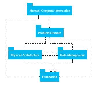
23 Layers (1) A layer represents an element of the software architecture of the evolving system. There should be a layer for each of the different elements of the system environment (e.g., data management, user interface, physical architecture). Like partitions and collaborations, layers also can be portrayed using packages and package diagrams
24
25 Layers (2) Foundation layer: It contains classes that are necessary for any object-oriented application to exist. They include classes that represent fundamental data types (e.g., integers, real numbers, characters, strings), classes that represent fundamental data structures, sometimes referred to as container classes (e.g., lists, trees, graphs, sets, stacks, queues), and classes that represent useful abstractions, sometimes referred to as utility classes (e.g., date, time, money). Problem domain layer: To further detail the classes so that it will be possible to implement them in an effective and efficient manner.
26 Layers (3) Data management layer: Addresses the issues involving the persistence of the objects contained in the system. The types of classes that appear in this layer deal with how objects can be stored and retrieved. Human computer interaction layer: Contains classes associated with the View and Controller idea. The primary purpose of this layer is to keep the specific user interface implementation separate from the problem domain classes. This increases the portability of the evolving system. Physical security layer: Addresses how the software will execute on specific computers and networks.
27 Package A package is a general construct that can be applied to any of the elements in UML models, for instance: To group use cases together to make the use-case diagrams easier to read and to keep the models at a reasonable level of complexity. To group classes and communication diagrams. To group packages.

28 Package Diagrams

29 Package Diagram of Package Diagram Layers for the Appointment System

30 Package Diagram of CD Selections Internet Sales System

31 Selecting a Design Strategy
32 Exercise Do s0me verification, validation, and balancing of your models built several weeks ago. Build a package diagram of your cases.

33
Rekayasa Perangkat Lunak 2 (IN043): Pertemuan 9. Human Computer Interaction Design and Physical Architecture Layer Design
: Pertemuan 9. Human Computer Interaction Design and Physical Architecture Layer Design") Rekayasa Perangkat Lunak 2 (IN043): Pertemuan 9 Human Computer Interaction Design and Physical Architecture Layer Design Principes of User Interface Design Layout The areas and information within areas
Rekayasa Perangkat Lunak 2 (IN043): Pertemuan 9 Human Computer Interaction Design and Physical Architecture Layer Design Principes of User Interface Design Layout The areas and information within areas
Object-Oriented Systems Analysis and Design Using UML
 10 Object-Oriented Systems Analysis and Design Using UML Systems Analysis and Design, 8e Kendall & Kendall Copyright 2011 Pearson Education, Inc. Publishing as Prentice Hall Learning Objectives Understand
Architectural Blueprint
 IMPORTANT NOTICE TO STUDENTS These slides are NOT to be used as a replacement for student notes. These slides are sometimes vague and incomplete on purpose to spark a class discussion Architectural Blueprint
SOFTWARE DESIGN COSC 4353 / Dr. Raj Singh
 SOFTWARE DESIGN COSC 4353 / 6353 Dr. Raj Singh UML - History 2 The Unified Modeling Language (UML) is a general purpose modeling language designed to provide a standard way to visualize the design of a
Software Service Engineering
 Software Service Engineering Lecture 4: Unified Modeling Language Doctor Guangyu Gao Some contents and notes selected from Fowler, M. UML Distilled, 3rd edition. Addison-Wesley Unified Modeling Language
13/11/2017. Meltem Özturan misprivate.boun.edu.tr/ozturan/mis515
 Meltem Özturan misprivate.boun.edu.tr/ozturan/mis515 2 1 Traditional Approach to Requirements Data Flow Diagram (DFD) A graphical system model that shows all of the main requirements for an information
Chapter 10. Object-Oriented Analysis and Modeling Using the UML. McGraw-Hill/Irwin
 Chapter 10 Object-Oriented Analysis and Modeling Using the UML McGraw-Hill/Irwin Copyright 2007 by The McGraw-Hill Companies, Inc. All rights reserved. Objectives 10-2 Define object modeling and explain
Rekayasa Perangkat Lunak 2 (IN043): Pertemuan 8. Data Management Layer Design
: Pertemuan 8. Data Management Layer Design") Rekayasa Perangkat Lunak 2 (IN043): Pertemuan 8 Data Management Layer Design Data Management Layer Focus on how to manage data are stored that can be handled by the programs that run the system, including:
Rekayasa Perangkat Lunak 2 (IN043): Pertemuan 8 Data Management Layer Design Data Management Layer Focus on how to manage data are stored that can be handled by the programs that run the system, including:
SE Assignment III. 1. List and explain primitive symbols used for constructing DFDs. Illustrate the use of these symbols with the help of an example.
 SE Assignment III 1. List and explain primitive symbols used for constructing DFDs. Illustrate the use of these symbols with the help of an example. There are essentially 5 different types of symbols used
Pattern for Structuring UML-Compatible Software Project Repositories
 Pattern for Structuring UML-Compatible Software Project Repositories Pavel Hruby Navision Software a/s Frydenlunds Allé 6 2950 Vedbaek, Denmark E-mail: ph@navision.com Web site: www.navision.com/services/methodology/default.asp
Patterns and Testing
 and Lecture # 7 Department of Computer Science and Technology University of Bedfordshire Written by David Goodwin, based on the lectures of Marc Conrad and Dayou Li and on the book Applying UML and (3
Object-Oriented Design and Modeling Using the UML
 Design Classes Object-Oriented Design and Modeling Using the UML Based on Chapter 18 of Whitten, Bentley, and Dittman: Systems Analysis and Design for the Global Enterprise (7th Ed). McGraw Hill. 2007
Software Development Methodologies
 Software Development Methodologies Lecturer: Raman Ramsin Lecture 3 Seminal Object-Oriented Methodologies: A Feature-Focused Review 1 Responsibility-Driven Design (RDD) Introduced in 1990; a UML-based
Chapter 2: The Object-Oriented Design Process
 Chapter 2: The Object-Oriented Design Process In this chapter, we will learn the development of software based on object-oriented design methodology. Chapter Topics From Problem to Code The Object and
FDD Process #1: Develop an Overall Model
 FDD Process #1: Develop an Overall Model A initial project-wide activity with domain and development members under the guidance of an experienced object modeller in the role of Chief Architect. A high-level
1 Executive Overview The Benefits and Objectives of BPDM
 1 Executive Overview The Benefits and Objectives of BPDM This is an excerpt from the Final Submission BPDM document posted to OMG members on November 13 th 2006. The full version of the specification will
For 100% Result Oriented IGNOU Coaching and Project Training Call CPD TM : ,
 Course Code : MCS-032 Course Title : Object Oriented Analysis and Design Assignment Number : MCA (3)/032/Assign/2014-15 Assignment Marks : 100 Weightage : 25% Last Dates for Submission : 15th October,
UML Fundamental. OutLine. NetFusion Tech. Co., Ltd. Jack Lee. Use-case diagram Class diagram Sequence diagram
 UML Fundamental NetFusion Tech. Co., Ltd. Jack Lee 2008/4/7 1 Use-case diagram Class diagram Sequence diagram OutLine Communication diagram State machine Activity diagram 2 1 What is UML? Unified Modeling
Introduction to Software Engineering
 Introduction to Software Engineering Gérald Monard Ecole GDR CORREL - April 16, 2013 www.monard.info Bibliography Software Engineering, 9th ed. (I. Sommerville, 2010, Pearson) Conduite de projets informatiques,
Chapter : Analysis Modeling
 Chapter : Analysis Modeling Requirements Analysis Requirements analysis Specifies software s operational characteristics Indicates software's interface with other system elements Establishes constraints
Chapter 1: Principles of Programming and Software Engineering
 Chapter 1: Principles of Programming and Software Engineering Data Abstraction & Problem Solving with C++ Fifth Edition by Frank M. Carrano Software Engineering and Object-Oriented Design Coding without
Object Model. Object Orientated Analysis and Design. Benjamin Kenwright
 Object Model Object Orientated Analysis and Design Benjamin Kenwright Outline Submissions/Quizzes Review Object Orientated Programming Concepts (e.g., encapsulation, data abstraction,..) What do we mean
Appendix A - Glossary(of OO software term s)
") Appendix A - Glossary(of OO software term s) Abstract Class A class that does not supply an implementation for its entire interface, and so consequently, cannot be instantiated. ActiveX Microsoft s component
Appendix A - Glossary(of OO software term s) Abstract Class A class that does not supply an implementation for its entire interface, and so consequently, cannot be instantiated. ActiveX Microsoft s component
Software Design Using CRC Cards
 By Harold Halbleib, Product Manager, Excel Software. Software Design Using CRC Cards Many notations, methods and books have been published in recent years regarding analysis and design of object-oriented
The requirements engineering process
 3 rd Stage Lecture time: 8:30-12:30 AM Instructor: Ali Kadhum AL-Quraby Lecture No. : 5 Subject: Software Engineering Class room no.: Department of computer science Process activities The four basic process
CHAPTER 9 DESIGN ENGINEERING. Overview
 CHAPTER 9 DESIGN ENGINEERING Overview A software design is a meaningful engineering representation of some software product that is to be built. Designers must strive to acquire a repertoire of alternative
5/9/2014. Recall the design process. Lecture 1. Establishing the overall structureof a software system. Topics covered
 Topics covered Chapter 6 Architectural Design Architectural design decisions Architectural views Architectural patterns Application architectures Lecture 1 1 2 Software architecture The design process
Fundamentals to Creating Architectures using ISO/IEC/IEEE Standards
 Fundamentals to Creating Architectures using ISO/IEC/IEEE Standards What to Architect? How to Architect? IEEE Goals and Objectives Chartered by IEEE Software Engineering Standards Committee to: Define
Presenter: Dong hyun Park
 Presenter: 200412325 Dong hyun Park Design as a life cycle activity bonds the requirements to construction Process of breaking down the system into components, defining interfaces and defining components
UNIT II Requirements Analysis and Specification & Software Design
 UNIT II Requirements Analysis and Specification & Software Design Requirements Analysis and Specification Many projects fail: because they start implementing the system: without determining whether they
Practical Database Design Methodology and Use of UML Diagrams Design & Analysis of Database Systems
 Practical Database Design Methodology and Use of UML Diagrams 406.426 Design & Analysis of Database Systems Jonghun Park jonghun@snu.ac.kr Dept. of Industrial Engineering Seoul National University chapter
Objectives. Explain the purpose and objectives of objectoriented. Develop design class diagrams
 Objectives Explain the purpose and objectives of objectoriented design Develop design class diagrams Develop interaction diagrams based on the principles of object responsibility and use case controllers
Meltem Özturan
 Meltem Özturan www.mis.boun.edu.tr/ozturan/samd 1 2 Modeling System Requirements Object Oriented Approach to Requirements OOA considers an IS as a set of objects that work together to carry out the function.
CS211 Lecture: Modeling Dynamic Behaviors of Systems; Interaction Diagrams and Statecharts Diagrams in UML
 CS211 Lecture: Modeling Dynamic Behaviors of Systems; Interaction Diagrams and Statecharts Diagrams in UML Objectives: 1. To introduce the notion of dynamic analysis 2. To show how to create and read Sequence
Basic Structural Modeling. Copyright Joey Paquet,
 Basic Structural Modeling Copyright Joey Paquet, 2000 1 Part I Classes Copyright Joey Paquet, 2000 2 Classes Description of a set of objects sharing the same attributes, operations and semantics Abstraction
Visualizing Verification. Adrian A. Marsh April 2004
 Visualizing Verification Adrian A. Marsh April 2004 Abstract This paper proposes extending UML modeling to system verification. Changing the utilization of the UML diagrams will increase the quality of
BridgePoint Modeling Exercises in Building Executable Models Mentor Graphics Corporation
 BridgePoint Modeling Exercises in Building Executable Models Mentor Graphics Corporation Published April 2013 Copyright 2006-2013 Mentor Graphics Corporation 1. Lab 1 1.1 Background BehindTheTimes Inc.
Examples. Object Orientated Analysis and Design. Benjamin Kenwright
 Examples Object Orientated Analysis and Design Benjamin Kenwright Outline Revision Questions Group Project Review Deliverables Example System Problem Case Studey Group Project Case-Study Example Vision
Interactions A link message
 Interactions An interaction is a behavior that is composed of a set of messages exchanged among a set of objects within a context to accomplish a purpose. A message specifies the communication between
Incremental development A.Y. 2018/2019
 Incremental development A.Y. 2018/2019 Incremental development Interleaves the activities of specification, development, and validation. The system is developed as a series of versions (increments), with
Object-Oriented Analysis and Design Using UML (OO-226)
") Object-Oriented Analysis and Design Using UML (OO-226) The Object-Oriented Analysis and Design Using UML course effectively combines instruction on the software development processes, objectoriented technologies,
Object-Oriented Analysis and Design Using UML (OO-226) The Object-Oriented Analysis and Design Using UML course effectively combines instruction on the software development processes, objectoriented technologies,
22/09/2012 INFO2110. Copyright Warning. Revision of class diagram. Overview. Purpose of class diagram. Generalization Relationship
 22/09/202 INFO20 Copyright Warning System Analysis and Modelling Semester 2, 202 Lecture 8, Structural Modelling (II) COMMONWEALTH OF AUSTRALIA Copyright Regulations 969 WARNING This material has been
Lecture 2 Arrays, Searching and Sorting (Arrays, multi-dimensional Arrays)
") Lecture 2 Arrays, Searching and Sorting (Arrays, multi-dimensional Arrays) In this lecture, you will: Learn about arrays Explore how to declare and manipulate data into arrays Understand the meaning of
Lecture 2 Arrays, Searching and Sorting (Arrays, multi-dimensional Arrays) In this lecture, you will: Learn about arrays Explore how to declare and manipulate data into arrays Understand the meaning of
Introduction to Software Engineering (2+1 SWS) Winter Term 2009 / 2010 Dr. Michael Eichberg Vertretungsprofessur Software Engineering Department of
 Winter Term 2009 / 2010 Dr. Michael Eichberg Vertretungsprofessur Software Engineering Department of") Introduction to Software Engineering (2+1 SWS) Winter Term 2009 / 2010 Dr. Michael Eichberg Vertretungsprofessur Software Engineering Department of Computer Science Technische Universität Darmstadt What
Introduction to Software Engineering (2+1 SWS) Winter Term 2009 / 2010 Dr. Michael Eichberg Vertretungsprofessur Software Engineering Department of Computer Science Technische Universität Darmstadt What
Chapter 6 Architectural Design. Chapter 6 Architectural design
 Chapter 6 Architectural Design 1 Topics covered Architectural design decisions Architectural views Architectural patterns Application architectures 2 Software architecture The design process for identifying
Lecture 1. Chapter 6 Architectural design
 Chapter 6 Architectural Design Lecture 1 1 Topics covered Architectural design decisions Architectural views Architectural patterns Application architectures 2 Software architecture The design process
Chapter 5: Structural Modeling
 Chapter 5: Structural Modeling Objectives Understand the rules and style guidelines for creating CRC cards, class diagrams, and object diagrams. Understand the processes used to create CRC cards, class
VANCOUVER Chapter Study Group. BABOK Chapter 9 Techniques
 VANCOUVER Chapter Study Group BABOK Chapter 9 Techniques May 27, 2015 David Ghotbi, CBAP Agenda Chapter 8 Review Pop Quiz Break Chapter 9 Review Pop Quiz Q & A 2 Chapter 9 Techniques Techniques: Alter
What is a Model? Copyright hebley & Associates
 Modeling Overview... as we know, there are known knowns; there are things we know we know. We also know there are known unknowns; that is to say we know there are some things we do not know. But there
Darshan Institute of Engineering & Technology for Diploma Studies
 REQUIREMENTS GATHERING AND ANALYSIS The analyst starts requirement gathering activity by collecting all information that could be useful to develop system. In practice it is very difficult to gather all
Designing Component-Based Architectures with Rational Rose RealTime
 Designing Component-Based Architectures with Rational Rose RealTime by Reedy Feggins Senior System Engineer Rational Software Rose RealTime is a comprehensive visual development environment that delivers
Object Oriented Analysis and Design - Part2(Design)
") Object Oriented Analysis and Design - Part2(Design) Exam A QUESTION 1 Which statement is true about elements within the subsystem and public visibility? A. Only the subset of elements that define the subsystems
Object Oriented Analysis and Design - Part2(Design) Exam A QUESTION 1 Which statement is true about elements within the subsystem and public visibility? A. Only the subset of elements that define the subsystems
Chapter 1: Programming Principles
 Chapter 1: Programming Principles Object Oriented Analysis and Design Abstraction and information hiding Object oriented programming principles Unified Modeling Language Software life-cycle models Key
Architectural Design
 Architectural Design Topics i. Architectural design decisions ii. Architectural views iii. Architectural patterns iv. Application architectures Chapter 6 Architectural design 2 PART 1 ARCHITECTURAL DESIGN
Architectural Design. Architectural Design. Software Architecture. Architectural Models
 Architectural Design Architectural Design Chapter 6 Architectural Design: -the design the desig process for identifying: - the subsystems making up a system and - the relationships between the subsystems
Abbreviated Systematica 4.0 Glossary Ordered by Concept Generic
 Term A collection of interacting Components. Terms for s Component Interact Sub-system Subject Environment Actor Logical Physical Interaction Role Sub-Interaction Feature Service Input-Output Architectural
SOFTWARE ENGINEERING AND PROJECT MAN AGEMENT
 SOFTWARE ENGINEERING AND PROJECT MAN AGEMENT Question: Difference between Verification and Validation? Answer: Verification ensures the product is designed to deliver all functionality to the customer;
Pertemuan 8. Object Oriented Modeling and Design
 Pertemuan 8 Object Oriented Modeling and Design References Rumbaugh, James et al., Object Oriented Modeling and Design, 1991, Prentice Hall, Inc., USA, ISBN: 0 13 629841 9 9 Coad, Peter and Yourdon, Edward,
Creating a Lattix Dependency Model The Process
 Creating a Lattix Dependency Model The Process Whitepaper January 2005 Copyright 2005-7 Lattix, Inc. All rights reserved The Lattix Dependency Model The Lattix LDM solution employs a unique and powerful
Enterprise Architecture Frameworks
 Enterprise Architecture Frameworks Learning Objective of Chapter 2 Topic: Enterprise Architecture Framework Content and structure of enterprise architecture descriptions This is necessary because Enterprises
UML Views of a System
 UML Views of a System The architecture of a system is the fundamental organization of the system as a whole. The five UML Views: Use Case View: focuses on scenarios Design View: focuses on the vocabulary
Credit where Credit is Due. Goals for this Lecture. Introduction to Design
 Credit where Credit is Due Lecture 17: Intro. to Design (Part 1) Kenneth M. Anderson Object-Oriented Analysis and Design CSCI 6448 - Spring Semester, 2002 Some material presented in this lecture is taken
Class diagrams. Modeling with UML Chapter 2, part 2. Class Diagrams: details. Class diagram for a simple watch
 Class diagrams Modeling with UML Chapter 2, part 2 CS 4354 Summer II 2015 Jill Seaman Used to describe the internal structure of the system. Also used to describe the application domain. They describe
SOFTWARE ARCHITECTURE & DESIGN INTRODUCTION
 SOFTWARE ARCHITECTURE & DESIGN INTRODUCTION http://www.tutorialspoint.com/software_architecture_design/introduction.htm Copyright tutorialspoint.com The architecture of a system describes its major components,
CS6100: Topics in Design and Analysis of Algorithms
 CS6100: Topics in Design and Analysis of Algorithms Guarding and Triangulating Polygons John Augustine CS6100 (Even 2012): Guarding and Triangulating Polygons The Art Gallery Problem A simple polygon is
Chapter 6 Architectural Design
 Chapter 6 Architectural Design Chapter 6 Architectural Design Slide 1 Topics covered The WHAT and WHY of architectural design Architectural design decisions Architectural views/perspectives Architectural
CS211 Lecture: Modeling Dynamic Behaviors of Systems; Interaction Diagrams in UML
 CS211 Lecture: Modeling Dynamic Behaviors of Systems; Interaction Diagrams in UML Objectives: 1. To introduce the notion of dynamic analysis 2. To show how to create and read Sequence Diagrams 3. To show
DATA STRUCTURES CHAPTER 1
 DATA STRUCTURES CHAPTER 1 FOUNDATIONAL OF DATA STRUCTURES This unit introduces some basic concepts that the student needs to be familiar with before attempting to develop any software. It describes data
UML- a Brief Look UML and the Process
 UML- a Brief Look UML grew out of great variety of ways Design and develop object-oriented models and designs By mid 1990s Number of credible approaches reduced to three Work further developed and refined
XIV. The Requirements Specification Document (RSD)
") XIV. The Requirements Specification Document (RSD) What is a RSD? What to include/not include in a RSD? Attributes of a Well-Written RSD Organization of a RSD Sample Table of Contents An Example 2002 John
XIV. The Requirements Specification Document (RSD) What is a RSD? What to include/not include in a RSD? Attributes of a Well-Written RSD Organization of a RSD Sample Table of Contents An Example 2002 John
Class diagrams. Modeling with UML Chapter 2, part 2. Class Diagrams: details. Class diagram for a simple watch
 Class diagrams Modeling with UML Chapter 2, part 2 CS 4354 Summer II 2014 Jill Seaman Used to describe the internal structure of the system. Also used to describe the application domain. They describe
MAHARASHTRA STATE BOARD OF TECHNICAL EDUCATION (Autonomous) (ISO/IEC Certified)
 (ISO/IEC Certified)") Subject Code: 17630 Model Answer Page No: 1 /32 Important Instructions to examiners: 1) The answers should be examined by keywords and not as word-to-word as given in the model answer scheme. 2) The model
Subject Code: 17630 Model Answer Page No: 1 /32 Important Instructions to examiners: 1) The answers should be examined by keywords and not as word-to-word as given in the model answer scheme. 2) The model
10조 이호진 이지 호
 10 조 200910045 이호진 200911415 이지호 According to the IEEE definition, design is.. The process of defining the architecture, components, interfaces, and other characteristics of a system or component 1.
UNIT 5 - UML STATE DIAGRAMS AND MODELING
 UNIT 5 - UML STATE DIAGRAMS AND MODELING UML state diagrams and modeling - Operation contracts- Mapping design to code UML deployment and component diagrams UML state diagrams: State diagrams are used
Chapter 6 Architectural Design. Lecture 1. Chapter 6 Architectural design
 Chapter 6 Architectural Design Lecture 1 1 Topics covered ² Architectural design decisions ² Architectural views ² Architectural patterns ² Application architectures 2 Software architecture ² The design
Use Case Model. Static Structure. Diagram. Collaboration. Collaboration. Diagram. Collaboration. Diagram. Diagram. Activity. Diagram.
 !"# $%&' !" #" $%%&&& ! Static Structure Diagram Collaboration Collaboration Diagram Collaboration Diagram Diagram Activity Diagram CRC Card CRC Card UML defines a standard notation for object-oriented
Object-Oriented and Classical Software Engineering DESIGN 11/12/2017. CET/CSC490 Software Engineering Design CHAPTER 14. Stephen R. Schach.
 Slide 14.1 CHAPTER 14 Slide 14.2 Object-Oriented and Classical Software Engineering DESIGN Eighth Edition, WCB/McGraw-Hill, 2011 Stephen R. Schach Overview Slide 14.3 Overview (contd) Slide 14.4 and abstraction
2.0.3 attributes: A named property of a class that describes the range of values that the class or its instances (i.e., objects) may hold.
 may hold.") T0/04-023 revision 2 Date: September 06, 2005 To: T0 Committee (SCSI) From: George Penokie (IBM/Tivoli) Subject: SAM-4: Converting to UML part Overview The current SCSI architecture follows no particular
T0/04-023 revision 2 Date: September 06, 2005 To: T0 Committee (SCSI) From: George Penokie (IBM/Tivoli) Subject: SAM-4: Converting to UML part Overview The current SCSI architecture follows no particular
Integrating TOGAF, Zachman and DoDAF Into A Common Process
 Integrating TOGAF, Zachman and DoDAF Into A Common Process Rolf Siegers Senior Principal Software Systems Engineer The Open Group Architecture Practitioner s Conference October 2003 Customer Success Is
Class object initialization block destructor Class object
 In this segment, I will review the Java statements and primitives that relate explicitly to Object Oriented Programming. I need to re-enforce Java s commitment to OOP. Unlike C++, there is no way to build
Software Development. Modular Design and Algorithm Analysis
 Software Development Modular Design and Algorithm Analysis Functional Decomposition Functional Decomposition in computer science, also known as factoring, refers to the process by which a complex problem
Chapter 7 Desain Rekayasa Perangkat Lunak Analysis Modeling. Software Engineering: A Practitioner s Approach by Roger S. Pressman
 Chapter 7 Desain Rekayasa Perangkat Lunak Analysis Modeling Software Engineering: A Practitioner s Approach by Roger S. Pressman Material Scenario-Based Modeling Flow Oriented Modeling Class-Bases Modeling
Software Design Patterns. Background 1. Background 2. Jonathan I. Maletic, Ph.D.
 Software Design Patterns Jonathan I. Maletic, Ph.D. Department of Computer Science Kent State University J. Maletic 1 Background 1 Search for recurring successful designs emergent designs from practice
Architectural Design. Topics covered. Architectural Design. Software architecture. Recall the design process
 Architectural Design Objectives To introduce architectural design and to discuss its importance To explain the architectural design decisions that have to be made To introduce three complementary architectural
Recalling the definition of design as set of models let's consider the modeling of some real software.
 Software Design and Architectures SE-2 / SE426 / CS446 / ECE426 Lecture 3 : Modeling Software Software uniquely combines abstract, purely mathematical stuff with physical representation. There are numerous
Rekayasa Perangkat Lunak
 Rekayasa Perangkat Lunak Untuk SISTEM KOMPUTER Kuliah 6: Arsitektur Perangkat Lunak Mohammad Iqbal Based-on slide Ivan Marsic Topik Desain Arsitektur Perangkat Lunak Keputusan Arsitektural & Key Concerns
(Traditional) Software Development Activities
 Software Development Activities") (Traditional) Software Development Activities Goals of the Unit A gentle and high-level introduction to software development activities Understanding what are the building blocks for producing software
(Traditional) Software Development Activities Goals of the Unit A gentle and high-level introduction to software development activities Understanding what are the building blocks for producing software
Analysis and Design with UML
 Analysis and Design with UML Page 1 Agenda Benefits of Visual Modeling History of the UML Visual Modeling with UML The Rational Iterative Development Process Page 2 What is Visual Modeling? Item Order
Lesson 3: Understanding General Software Development
 Lesson 3: Understanding General Software Development 1. Arrange the various activities of an application lifecycle in the order in which they are likely to occur. a) Requirements analysis, design, coding,
Abstraction. Design fundamentals in OO Systems. Fundamental Software Development Principles
 Abstraction Design fundamentals in OO Systems Tool for abstraction: object Object structure: properties and values for those properties operations to query and update those properties We refer to the collection
CS301 - Data Structures Glossary By
 CS301 - Data Structures Glossary By Abstract Data Type : A set of data values and associated operations that are precisely specified independent of any particular implementation. Also known as ADT Algorithm
20. Business Process Analysis (2)
") 20. Business Process Analysis (2) DE + IA (INFO 243) - 31 March 2008 Bob Glushko 1 of 38 3/31/2008 8:00 AM Plan for Today's Class Process Patterns at Different Levels in the "Abstraction Hierarchy" Control
20. Business Process Analysis (2) DE + IA (INFO 243) - 31 March 2008 Bob Glushko 1 of 38 3/31/2008 8:00 AM Plan for Today's Class Process Patterns at Different Levels in the "Abstraction Hierarchy" Control
Motivation State Machines
 Motivation State Machines Generating test cases for complex behaviour Textbook Reading: Chapter 7 We are interested in testing the behaviour of object-oriented software systems Behaviour: Interactions
Software Development Methodologies
 Software Development Methodologies Lecturer: Raman Ramsin Lecture 8 Agile Methodologies: XP 1 extreme Programming (XP) Developed by Beck in 1996. The first authentic XP book appeared in 1999, with a revised
Software Testing. Software Testing. in the textbook. Chapter 8. Verification and Validation. Verification and Validation: Goals
 Software Testing in the textbook Software Testing Chapter 8 Introduction (Verification and Validation) 8.1 Development testing 8.2 Test-driven development 8.3 Release testing 8.4 User testing 1 2 Verification
CS504-Softwere Engineering -1 Solved Objective Midterm Papers For Preparation of Midterm Exam
 CS504-Softwere Engineering -1 Solved Objective Midterm Papers For Preparation of Midterm Exam MIDTERM EXAMINATION 2010 Question No: 1 ( Marks: 1 ) - Please choose one By following modern system engineering
LABORATORY 1 REVISION
 UTCN Computer Science Department Software Design 2012/2013 LABORATORY 1 REVISION ================================================================== I. UML Revision This section focuses on reviewing the
Object Visibility: Making the Necessary Connections
 Object Visibility: Making the Necessary Connections Reprinted from the October 1991 issue of The Smalltalk Report Vol. 2, No. 2 By: Rebecca J. Wirfs-Brock An exploratory design is by no means complete.
Lecture Notes UML UNIT-II. Subject: OOAD Semester: 8TH Course No: CSE-802
 UNIT-II Lecture Notes On UML IMPORTANCE OF MODELING, BRIEF OVERVIEW OF OBJECT MODELING TECHNOLOGY (OMT) BY RAMBAUGH, BOOCH METHODOLOGY, USE CASE DRIVE APPROACH (OOSE) BY JACKOBSON. KHALID AMIN AKHOON 1
An Information Model for High-Integrity Real Time Systems
 An Information Model for High-Integrity Real Time Systems Alek Radjenovic, Richard Paige, Philippa Conmy, Malcolm Wallace, and John McDermid High-Integrity Systems Group, Department of Computer Science,