User Manual for X3 MDVR GUI. Mobile Digital Video Recorder
|
|
|
- Alexander Tucker
- 5 years ago
- Views:
Transcription


1 User Manual for X3 MDVR GUI Mobile Digital Video Recorder
2 NOTICE The information in this manual was current when published. The manufacturer reserves the right to revise and improve its products. All specifications are therefore subject to change without any notice. The purpose of this manual is to kindly aid the user for the operation for our MDVR (especially for GUI setting). The user should have a basic understanding of computer operation and basic knowledge of how to connect peripherals and make some settings. 2
3 1 PRODUCT CHARACTERISTICS AND OVERVIEW PRODUCT OVERVIEW VIDEO/AUDIO FERATURES AND CAPABILITIES REMOTE CONNECTION CAPABILITIES ACCESSORY MODULES FOR MDVR HANDHELD IR REMOTE CONTROL NUMERIC KEYPAD SETUP MENU NAVIGATION OTHER KEYS FUNCITONS PTZ FUNCTION KEYS MENUTREE SYSTEMSTARTUP SEARCH and PLAYBACK VIDEO FILE ALL FILES EVENT FILES SETUP SYSTEM DATA/TIME GENERAL REGISTER INFO FORMAT UPGRADE USER SECURITY CONFIG SYSTEM LOG GEO-FENCING RECORD OPTIONS OSD OVERLAY CAMERA SETTING RECORD SETTINGS SUB-STREAMING SCHEDULE OTHER SETTING NETWORK SERVER LOCAL NETWORK WIFI SETUP MOBILE NETWORK EVENT SENSOR SENSOR OUTPUT
4 6.4.3 SPEED ACCELERATION TEMPERATURE CAMERA VOLTAGE PERIPHERAL PTZ EXT.COM SETUP INFORMATION SYSTEM HISTORY MODULES
5 1 PRODUCT CHARACTERISTICS AND OVERVIEW 1.1 PRODUCT OVERVIEW SVT-MDVR-X3 is a cost-effective and functional Mobile Digital Video Recorder specially designed for vehicle surveillance and remote monitoring, combined with high-speed processor and embedded operating system. The advanced H.264 video compression and decompression, GPS location make it to be a very powerful and perfect solution for vehicles VIDEO/AUDIO FERATURES AND CAPABILITIES 4 channels for video and audio inputs, 2 channel real-time D1, 4CH D1 at 12fps/15fps continuous or priority video recording and live view display. Semi-transparent GUI makes setting for GUI and live display synchronously. Special file system NVRFSTM is very good for improving the security level of data, providing self-recovery function, self-check, self-backup for certain critical data and avoiding data fragment that affect system efficiency. Watermark prevents any modification in recorded file, which is part of the law enforcement. Better Compression rate at H.264 (50% less than MPEG4).Enhance recording storage rate in most efficiency way. 4 channels for high-fidelity, digitally recorded, synchronized audio matched to 4 video channels User friendly criteria to playback the events associated video only. Dual-Stream for wireless transmission depends on wide or narrow bandwidth. User-selectable settings for quality and audio record enable/disable for each video channel. 12v power supply for multiple devices such as cameras, sensors, relays and any other accessories. Selectable frame rate with event-triggered burst recording speeds up to 30FPS/camera. Multiple alarm inputs with selectable pre-alarm and post-alarm record timings REMOTE CONNECTION CAPABILITIES Handheld Infra-Red controller with OSD for quick access to recorded video and settings menu. PC-Based Client software for live viewing, playback video, playback events video and download capabilities Support CMS (Central Management System) for remote monitoring by 3G (HSDPA or EVDO) and WIFI, PAS (Playback Analysis Software) for video playback, meta-data analysis ACCESSORY MODULES FOR MDVR Video Interface Module including GPS location and speed. Control panel for driver s simply operation. Vehicle Motion Manager includes 3-axis Inertia Sensor to determine video-matched motion events. Wireless module GPRS /3G, WIFI for transferring data to CMS server for remote monitoring. 5


6 2 HANDHELD IR REMOTE CONTROL Numeric Input Keys Use the numbers to input Values in the system setup Screen or switch through the channels in live view. Navigation Arrows Use the ARROW keys to move between selections, input fields and icons. Press ENTER to select And EXIT to return. Next and previous is also used to increase or decrease volume when at live or search screens. Each MDVR includes a handheld Infra-Red (IR) controller that allows the user to transmit commands to recording module and display on screen control menu 6
7 2.1 NUMERIC KEYPAD [0-9] keys: During setup, number keys are used to input number values. In live view window, you can press 1, 2, 3 and 4 to switch to full screen, and press 0 to switch to quad view. During full screen view of each camera, you can press key to adjust contrast, luminance, color and saturation, and then press + and - to make the adjustments. Pressing will navigate through the color adjustment options. 2.2 SETUP MENU NAVIGATION, : Up, down directional keys: Move selection up and down in setup menu., : Left, Right directional keys: Move cursor left or right in setup menu. [ENTER] key: During setup, select and save the settings 2.3 OTHER KEYS FUNCITONS You can press LOGIN / LOCK or SETUP key to enter the GUI to setup. If LOGIN/ LOCK POWER password enabled, you have to input default Admin password: To reset the MDVR in to sleep mode (You can press power button again to let MDVR start up when it in sleep mode). Switch full screen of one channel to quad view. Brightness, contrast, color adjustment for per channel. Use [+] [-] button to change the values. You have to adjust the values for each channel individually. SETUP EXIT Stop Record PAUSE/STEP PLAY Login GUI to setup the parameters. Return to the previous menu. Used to stop the recording manually. Only valid when you setup the record mode as manual. Used to start the recording manually. Only valid when you setup the record mode as manual. Freezes playback to a single frame and can advance one frame at a time. To advance the frame press Pause / Step to move frame by frame. Press EXIT to return to normal playback speed. Starts/Resumes playback from any other mode (FF, RR, Frame by Frame etc). 7
8 SLOW Reduces playback speed to 1/2, 1/4, 1/8 modes. Press PLAY to return to normal playback speed. Quick search mode when you playback the record file in MDVR. Press GOTO GOTO button and input the desired time, and the select SURE to jump to the specific time you want to playback. NEXT Increase volume while playback (if audio is recorded). PREV Decrease volume while playback (if audio is recorded). REW Rewinds the video while playback. X2 and X 4 modes available. FWD Fast forward the video while playback. X2 and X4 modes available. CF No use at present. [F1] Export all the event record files of the day to USB by press F1 key. [F2],[F3],[F4] Reserved for future use. 2.4 PTZ FUNCTION KEYS While connect with PTZ camera and using the RS485 in DB26, following commands can control with PTZ camera with following function: [ZOOM IN +], [ZOOM OUT -] [IRIS +], [IRIS-] [FOCUS +], [FOCUS -] PTZ AUTO PRESET RECALL BRUSH ZOOM IN/OUT Brightness control Focus control Enable the PTZ function AutorunwiththePTZpattern Preset default position Recall the position that you have setup. Brush the glass screen Check battery in place of remote controller since no battery in the standard package 8
9 3 MENU TREE M-X3-V35 Menu structure tree 9
, connect the black wire to GND.")
10 M-X3-V35 4 SYSTEM START UP Install the HDD/SD card first and then lock it in front panel. For testing, just connect the red wire and yellow wire together to Power + (8~36V DC), connect the black wire to GND. If on vehicle, please connect red wire to power +, yellow wire to Ignition, black GND wire to power -. SYSTEM LOGIN FOR SETUP MDVR GUI is semi-transparent; you can see the live view when you make GUI configurations 10
11 M-X3-V35 When Password is set disable, press SETUP key on the handheld controller into the setup menu directly; When Password is set enable, press LOGIN/LOCK OR ENTER key on the handheld controller, the setup menu will appear: UNIT ID: The unit ID of MDVR. You make the ID setting in the GUI and then the NO. will display on screen automatically. PASSWORD: Enter the admin password or user password. User default password is , and Admin password is OPERATOR PASSWORD CORRECT indicates permission is limited to video, sensor menu. ADMIN PASSWORD CORRECT indicates full access to MDVR. SUPER PASSWORD CORRECT indicates full access to MDVR under the circumstance of losing the password and modifies the MAC address. Keyboard: Press ǏEnterǐto use keyboard to type device ID and password. 1 0~9, number key, pressǐenterǐto select the number : Input type shift key. (Number, capital, small letter) 3 Ǐĸǐdelete, Ǐ ǐexit. 11

12 5 SEARCH and PLAYBACK VIDEO FILE This part is for search and playback the video file on the MDVR directly. 5.1 ALL FILES You can search all the video files including normal files, alarm files by record time and file type. Please highlight the option ALL FILES and then enter into following screen. FILE SOURCE: User can choose to playback from the HDD or from the SD for mirror recording. FILE TYPE: The type of the file including all file, alarm file and normal file. CHANNEL: Select the channel you want to search. DATE: MDVR system will display the current day automatically. The day with record files will be indicated by 12

13 green. If the day with ALARM FILES, it will indicated by red. START TIME: The default setting is 00:00:00; this time is for the start time for recording. END TIME: The default setting is 23:59:59; this time is for the end time for recording. For example: If the date is 2011_04_14, the start time is 00:00:00 and end time is 23:59:59. it indicates you want to search the entire video file from 00:00:00 to 23:59:59 on 14 th, Apr, If the date is 2011_05_16, the start time is 12:56:00 and end time is 13:10:20, then it indicates you want to search all the files from 12:56:00 to 13:10:20 on 16 th,may,2011. Remark: the Green color means the record file of this day is normal record file, Red color means there is alarm files during this day. Please press SEARCH to enter into the next menu for listing out all the certain video files depends on the setting for the file type, date and time. SEL: For selecting the files for backup. Please press arrow key on remote control to select the file that need to back up and then will display. REV.: Press for selecting all the other files. For example, if you do not select any file for backup, then press REV., all the files are selected. If you select one file and then press REV., all other files are selected. (But the selected one will not be selected) Lock: L means this file is locked. U Means this file is unlocked. Lock means the alarm file is protected for the configured days to avoid being overwritten. Go to SETUP--EVENT, for each kinds of alarm, you can enable or disable the lock function in the setting interface. EXPORT: Export the selected file to external device by USB port in the front of MDVR. Please connect the external storage device with MDVR by USB port and then press EXPORT to backup. Then the following screen will pop up. 13

14 TOTAL: total quantity for the files that you selected for back up. No.: The file No. that is backing now. After successful backup, the following screen will pop up. If you do not connect external storage device or the storage device is defective, then the system will display NO THUMB DRIVE. If the MDVR current video type is different with the setting that the MDVR record last time, then the video file can not playback, for example, the video type of record files is NSTC, now the setting of video type is PAL, you can t playback the video file until you change the video type to NSTC. Another example: if you change the video type to NTSC, then after the MDVT reboot, you can't playback the previous video files recorded in PAL, as the following picture: 14
 on 4 channel MDVR. 5.2 EVENT FILES Search for all the event files LOG, not video file.")
15 M-X3-V35 Please enter into the OPTION GUI and change the video type to be PAL manually and then the video file can be playback, otherwise, can not. Also, if the HDD is used on 8-CH MDVR before, then you can't playback the video files(recorded on 8CH MDVR) on 4 channel MDVR. 5.2 EVENT FILES Search for all the event files LOG, not video file. FILE TYPE: The type of the alarm file including I&O / ACCELERATION/ SPPED/TEMP/ VL ALARM/MOTION DETECTION/BLIND and so on DATE: MDVR system will display the current date automatically. The date with alarm record files will be indicated by yellow. 15

16 Please press SEARCH to enter into the next menu to list out all the certain video files depends on File s type and date. SEL: For selecting the LOG for backup. Please arrow key on remote control to select the LOG file that need to back up and then will display. Please press REV. to select all the files for backup or not. EVENT NAME: The name for the alarm such as alarm for video loss, alarm for over speed, low speed or high temperature, sensors and so on. DATE: Display the date when the alarm occurred. TIME: The start time when the alarm occurred. REV.: Press for selecting all or not. For example, if you do not select any file for backup, then press REV., all the files are selected. EX LOG: Export the selected LOG to external device by USB port on the front of MDVR. EXPORT: Export the related video if the event has the record file. If no related video file, you will got a remark that no video file. It is just LOG file for event name, start time, not video file. If you want to see the alarm video, please search them in ALL FILES menu. 16
17 6 SETUP This part will show you how to setup the MDVR and how to check the working status. Please press SAVE to make all the setting valid and it will give you a remark when you save successful, and when you modify the settings for the network, it will restart automatically after you exit to live view. The MDVR will stop recording when enter into the MDVR configuration GUI. You can input the letters and characters by software keyboard. 6.1 SYSTEM Use ARROWS to select and press ENTER. The screen will show the menu as below: 17

18 6.1.1 DATA/TIME M-X3-V35 DATE FORMAT: Press ENTER to select different format MM/DD/YYYY, DD/MM/YYYY, YYYY-MM-DD TIME FORMAT: 12H or 24H, Press ENTER to select different format. TIME SYNC SOURCE: The system allow have the time synchronizing via by either GPS or NTP. A: While selecting the GPS, the device must have GPS connection and GPS signal must be have well reception signal. To set the sync time in this menu, and unit will record the time difference-gmt offset, when the system time arrive the sync time, unit will synchronize with GPS time once. B: While selecting the NTP (Network Time Protocol), the device must have network access connection and assign the NTP IP location; This process run at 6:30am local time while the system have network connection; TIME ZONE: Please choose the correct time zone where vehicle in. SYNC TIME: This is the time when the unit will sync the system time every day. The method depends on the setting on the TIME SYNC SOURCE option: NTP SERVER IP: Input the IP server which supports NTP protocol, in order to allow the system have time synchronization through the network. [Example: " ", " ", " ", " "] DST: Daylight Saving Time. Only when it set on, the following option will available. DST MODE: There are two modes: Auto / Manual. Auto: According to the international DST, i.e.: valid only between2amonsecondsuninmarchand2amonfirstsuninnov. While setting the DST, the former date must be earlier than the latter; if the two setting Date is the same, the DST will invalid. Scroll to SAVE to make the setting valid. 18
 IGNITION: for shut down delay function.")
 TIMER: It will start up automatically at the time you setup.")
19 6.1.2 GENERAL M-X3-V35 ON/OFF TYPE: There are IGNITION, TIMER and IGNITION OR TIMER three options. A) IGNITION: for shut down delay function. For example: If you setup the SHUT DOWN DELAY as 5 min, then MDVR will shut down after 5 min after the ignition off. B) TIMER: It will start up automatically at the time you setup. If you select TIMER, then the following screen will pop up. C) IGNITION OR TIMER: means include both conditions. 19

20 BOOT UP TIME: The exact time for MDVR starts to work every day. SHUT DOWN TIME: The exact time for MDVR shut down every day. BOOT UP IN RECORDING TIME: ON means record function linkage to timer start-up. For example, if the setting for BOOT UP TIME is 6:00:00, then when it is 6:00:00, MDVR will start to record even ignition is OFF. BUZZER SWITCH: ON means the built-in buzzer will beep when alarm happens, OFF means no audio when alarm happens. Beeping time depends on the ALARM TIME in SETUP-RECORD-OPTION IDLE TIME (SEC): The time for the operation interface switch to the live view. if the user does not make any operation for some time, the system will switch to the live view automatically. EVENT FILES AUTO-EXPORT (USB):When is switch is ON, you can back up all the alarm record files of today by press F1 on IR control in live view mode. For TIMER type, if the setting for boot up time is 6:00:00 and shut show time is 11:00:00. After the MDVR is OFF, reboot up the MDVR and MDVR will check the system for 5 min and then shut down again, you must enter into this menu to change the TYPE to be ignition. Anyway, if the time for reboot up the MDVR is not during 6:00:00 to 11:00:00, then MDVR will shutdown in 5 min. OUTPUT MODE: There are 4:3 and 9:6 two options, you can select the mode you want. TRANSPARENCY: Setup the brightness for the screen display as you want. Scroll to SAVE to make the setting valid 20
.")
21 6.1.3 REGISTER INFO M-X3-V35 UNIT S/N: The series Number for MDVR. One MDVR has only one S/N. This number is read from special encrypted chip. UNIT ID: Device ID. Use the NUMERIC keypad to enter the system ID from to This ID is used when logging in to the unit (if security is enabled). COMPANY NAME: The name of company, Press the arrow key on the remote control and highlight this Option and then input the name of the company. VEHICLE NO.: The number of the vehicles. DRIVER/ROUTE NAME: The driver s name and the route name DEVICE ID: This ID should be unique and it is very important for the message server of CMS, WCMS, and ADS. Only this number can be recognized by message server. Remark: when you connect MDVR to PC software, make sure vehicle NO and DEVICE ID is not blank, otherwise, it can t connect to message server. Scroll to SAVE to make the setting valid FORMAT Select the device you want to format, Video Storage, SD card or USB. 21

22 DEVICE: Please press ENTER to select the target device for format. There are 2 options: Video Storage/ SD/USB. Then choose format method, there are three methods optional: FAST FORMAT: MDVR would clear all the video data directly. SLOW FORMAT: MDVR would detect before format, if there are bad blocks, it would mark them out and would not record here next time. Detect Video Storage: MDVR just detect the video storage media, no format at all. After format success, it will restart UPGRADE Upgrade to new firmware or MCU. FIRMWARE: Upgrade the firmware. MCU: Upgrade MCU. HOW TO UPGRADE THE FIRMWARE: 1. Please create one folder named dvrupgrade in thumb drive and then copy the firmware upgrade file into this folder. 2. Insert the thumb drive into the USB port in the front panel of MDVR. 22
23 3. Please enter into this interface and press UPGRADE, MDVR will upgrade the firmware automatically. 4. During the firmware upgrade, then following screen will pop up. 5. After upgrade success, it will restart automatically, as follow: Please do not cut off the power for MDVR or remove the thumb drive during firmware upgrade. Please check the firmware version after the MDVR reboot up and make sure that the firmware upgrade is completely successful. If the firmware of the MDVR is the latest, then you can not upgrade the firmware again. And MDVR system will pop up one screen as following: 23

24 MCU UPGRADE: The step is the same as upgrade firmware. LOGO: update the starting interface. For our standard firmware, when the system starting up, you can see SYSTEM INITIALIZENG interface. With this function, you can change this interface to your own logo. The requirements are as following: 1) The picture must be JPEG format and generated by paint in windows OS, 2) Resolution: 720*576 3) File name: logome.jpg 4) File size: <100KB 5) Upgrade method: the same to upgrade firmware, put this file to dvrupgrade folder in root of USB drive. UPDATE: when you update the firmware, there is screen to show you UPDATING..., with this function, you can change this interface to your own logo. The method and requirements of this picture are the same as upgrade logo, but the file name should be update.jpg USER SECURITY Setup the password for user and admin. 24


25 PASSWORD ENABLE: To active this function or not. Selecting ON will require a password in order to access the setup menu. Selecting OFF will not require a password in order to access the setup menu. USER PASSWORD: User can only search, can t modify any parameters. ADMIN PASSWORD: An Administrator with full rights The default password for Admin is Re-enter must be same input as first password, otherwise the system would not accept the password setting when password does not match between the first and re-enter line. Then the following screen will pop up: Scroll to SAVE to make the setting valid CONFIG Restore the default setting and export and import the MDVR configuration. 25

 and then press IMPORT. The configuration will be imported to this MDVR automatically.")
26 EXPORT: Export all the configuration for the MDVR to another MDVR to make sure that two MDVR have the same setting. Please insert the external storage device to the USB port and then press EXPORT, Then the configuration file will backup to the external device. IMPORT: Import the MDVR configuration file to the current device, except MAC address, LOCAL IP, WIFI IP and register information. Please insert the external storage device to the USB port (Must have configuration file in the storage device) and then press IMPORT. The configuration will be imported to this MDVR automatically. RESTORE: Restore default settings SYSTEM LOG You can export or delete the system log in this interface, as following picture: Remark: The user log mainly include: start record time, event time, stop recording time, power on and power off time and so on. 26

27 6.1.9 GEO-FENCING M-X3-V35 EXPORT THE GEO-FENCING CONFIG FILE: Export all the GEO-Fencing configuration for the MDVR to another MDVR to make sure that two MDVRs have the same settings. Please insert the external storage device to the USB port and then press EXPORT, Then the configuration file will backup to the external device. IMPORT THE GEO-FENCING CONFIG FILE: Import the MDVR GEO-Fencing configuration file to the current device. Please insert the external storage device to the USB port (Must have configuration file in the storage device) and then press IMPORT. The configuration will be imported to this MDVR automatically. 6.2 RECORD Setup the related configuration for Record 27

28 6.2.1 OPTIONS M-X3-V35 Setup the basic parameters. VIDEO TYPE: PAL and NTSC optional. The default setting is NTSC RECORD MODE: Record mode, three modes as following: GENERAL: When MDVR is power on and start up, the MDVR will start to record automatically. TIMER: record according to schedule in SETUP--RECORD-SCHEDULE. EVENT: When event trigged, MDVR will start to record. NORMAL REC RATE: normal record rate, two option: NORMAL: MDVR will start to record according to the setup of RECORD SETTING. IFRAME:MDVR only record at one frame per second in order to take less space of hard drive. BUT when event is trigged, MDVR will record according to setup of RECORD SETTING. ALARM PRE-REC TIME 1-60 MIN: Pre-record time setting is from 1 to 60 minutes. For example: If the setting for pre-record is 30min, when alarm trigger at 10:30, then the record file start from 10:00 to 10:30 will pack as alarm record. (Make sure the Pre-recording switch is ON in next page when you want to use this function) ALARM DURATION 3-30 SEC: The alarm duration time, all the alarm for same type considered to be one alarm during the setting for alarm duration and MDVR reset the duration time automatically. For example, if the setting for alarm duration is 10 sec and during this 10 sec, anther same type alarm triggered and then MDVR system will consider them to be one alarm event. And the alarm start time will be reset based on the second time for alarm. ALARM POST REC SEC: Alarm post recording time. ALARM TIME: buzzer alarm duration time setup, when alarm triggered, the buzzer duration time. 28


29 MEDADATA CAPTURE: metadata information, it will create a black box file in HDD when you enable this switch. RECORD FILE TIME MIN : Recording file packing size, 15, 30, 45, 60 minutes optional. HDD/ SD OVERWRITE: To make the HDD or SD overwrite when there is only 2GB space in HDD. LOCKED FILE RETENTION (DAY): Locked recording file save time: 7, 10, 15, 20, 30, 45 days optional, during the save time, the locked recording file won t be deleted. Once pass lock time, the recording file LOCK identifier will be from L to U, and then can be deleted. PRE-RECORDING SWITCH: Only when this is sent as "ON" the pre-recording time is valid. SD CARD TYPE: Internal means the one in the SD card slot below the HDD case; External means the one in file-proof box. Mirror Rec. To SD CARD: For MDVR to backup recording files to SD card when backing up to hard disk OSD OVERLAY During Live view, press Enter on remote control to show MDVR working status on live view. 29

30 DATE/TIME: Display date and time on OSD. ALARM: Display Alarm information on OSD. FIXED means show the alarm information all the time on image. ACCEL DATA: Display the information for inertial sensor TEMPERATURE: Display the temperature on OSD FIRMWARE VER: Display the current firmware version GPS INFO: Display the GPS working status. TRIGGER means only when GPS is available, it will be shown. CHANNEL NAME: Display the channel name. VEHICLE NO.: Display the vehicle NO., SPEED: Display vehicle speed info. If all the options are ON, Then the following screen will pop up after you press Enter during live view. 30
 AUDIO: Active the audio record function LIVE: to")

31 6.2.3 CAMERA SETTING Setup enables record function and live view for each channel. ENABLE: Enable the record function. NAME: The name of the channel. For example, if you setup the name of CH1 is ABC, and you can see ABC three letters display on the live view (for channel 1) AUDIO: Active the audio record function LIVE: to display the live view ROUND: Means channel loop function, if you setup time as 5 second, which means the channel will change to full screen from channel 1 to 4. VOICE INTERCOM: it's a switch for talk function. It can only be initiated from the server side. The audio of 4 th channel is used for this function. So when there is voice intercom, the video file of this channel has no audio. 31


32 6.2.4 RECORD SETTINGS M-X3-V35 Make configuration for Resolution, frame rate, image quality parameter setting for each channel. RES: Resolution, D1, HD1, CIF optional. For example: D1 resolution is , HD1 resolution is , and CIF resolution is FPS: Frame rate, frames per second, 1~25 can adjust. QUANLITY: Image quality, 8 levels optional, Level 1 is the best. Normal quality is the quality for normal record, and alarm quality is for alarm record SUB-STREAMING This is used for video transmission to WCMS software which won't affect the recording on MDVR. There are two modes SUB-STREAM, mode 1 is for broad bandwidth, such as connect in LAN or WIFI, mode 2 is for wireless transmission like GPRS or 3G. When you selected MODE1, and then press SURE, you will enter into the interface as follow: 32


33 EN: Enable this channel or not. If it is OFF, then you can't get video from this channel. It shows black window in CMS client. RES: Resolution, CIF. FPS: Frame rate, frames per second, 1~25 adjustable. QUALITY: the quality of video transmission. Kbps: Means the decode rate of the video transmission. When you selected MODE2, and then press SURE, you will enter into the interface as follow: BAND WIDTH: Setup the band width for video transmission, for 3G, it can be 500~800. EN: Enable the channel or not. RES: Resolution, CIF. FPS: Frame rate, frames per second. SUB-STREAM MODE: adapt and fix two options, adapt means it will adjust the bit rate and frame according to the bandwidth of network, fix means it will transmit as the bit you setup, when the bandwidth is not enough, the video may not smoothly. 33
 **********: Choosing the asterisks will suspend the highlighted schedule Type:")
34 6.2.6 SCHEDULE M-X3-V35 Date: Press ENTER to change the period of time to control the recording schedule Single Day: Choose the name of a day to create a recording schedule Every Day: Choose Every to apply a schedule to every day of the week Weekday: Schedule will only apply Weekdays (weekday is from Monday to Friday) **********: Choosing the asterisks will suspend the highlighted schedule Type: Press ENTER to change the type of the recording mode: Normal: Continuous recording Alarm: Alarm recording B.D.: Blind detection recording M.D.: Motion detection recording Schedule 1 / 2: Press the RIGHT ARROW key to enter values using the NUMERIC keypad into any time field; Schedule 1 is the first of two possible ON/OFF cycles that apply to any day in the period chosen under Date. Schedule 2 is the second cycle for any day in the period. There is no need to overlap times of Schedule 1 and Schedule 2. Ending at 23:59 of one day and beginning with 00:00 of the next day will provide continuous recording without interruption (factory default setting) When same date/time, on the condition that the schedule set as NORMAL type, priority record also can be available. Then Sensor can trigger full frames recording. 34
 WATERMARK: This is a technical to protect original data from illegal modification, as long as you setup water mark,wewillfindthedifferencewhenweanalysistherecordfiles.")
35 6.2.7 OTHER SETTING M-X3-V35 A) INITIALIZE INTERFACE: LIVING is to show the live view image in LCD monitor; CP3 MENU is to show the CPS setting menu. B) WATERMARK: This is a technical to protect original data from illegal modification, as long as you setup water mark,wewillfindthedifferencewhenweanalysistherecordfiles. INTERCOM SENSOR: This is to set the intercom function of CP3. If you choose Sensor1, you must also set as follow: >>EVENT>>SENSOR ENABLE SENSOR 1>>ON NAME: INTERCOM or any other short name SET: choose HIGH C) EXPORT MINIPLAYER: Press ENTER to export MINIPLAYER to USB thumb drive. So when insert the USB to other computers, you can just run it to playback video file. 35
 software, require assigned the IP address to allow MDVR can sending")
.")
36 6.3 NETWORK M-X3-V SERVER The sever IP and port setting for CMS software. MESSAGE SERVER: While using the CMS (Center Management System) software, require assigned the IP address to allow MDVR can sending the video and data to this destination. This server IP must be the same with the server IP of CMS (the IP of the PC that installed message server). CMS is used in LAN by WIFI or local network, or via 3G wireless module. PORT: please use the default port 5556 here. MEDIA SERVER IP AND PORT: NO use at present. 36

37 Please refer to the detailed manual for CMS settings in this part LOCAL NETWORK Local IP is the IP setting for the MDVR to make sure that MDVR can go online Must enter a fixed IP address to use Network capabilities, please consult with local Internet Service Provider for the information. Use NUMERIC keypad to enter the TCP/IP address information: IP: Enter the static IP address SUB: Enter the subnet mask GATE: Enter the gateway that the MDVR through to network CLIENT PORT: can't be 0 for IE login WEB PORT: the port for IE login. That is input the MDVR's WIFI or Local IP on IE address bar to access the MDVR for live view/playback/setup or upgrade. For example: type is the web port. If you don't change this port, just enter the IP to access. MAC Address: MAC address is uniquely and cannot change it. 37


38 6.3.3 WIFI SETUP M-X3-V35 When choose ON, the following screen will pop up. GET IP TYPE: There are two options; STATIC IP means you have to arrange a static IP for WIFI sever, and AUTO IP means it will get a dynamic IP, and make sure the DHCP function is OK. IP: Enter the static IP address of built-in WIFI. SUB: Enter the subnet mask GATE; Enter the gateway that the MDVR through to network ESSID: The AP name of this WIFI server. PSSWORD ENABLE: if the WIFI server need password, you can input it here, and please make sure it less that 5 digitals MOBILE NETWORK This interface is the network setup for wireless modules, and SIM card, please select the corresponding mode for your SIM card, when you connect in LAN, please select NONE. 38
, here you must setup the type as WCDMA.")

39 1) MODULE TYPE Choose the module type here: GPRS/ CDMA/ EVDO/ WCDMA/ EDGE/ TD-WCDMA/ NONE. Note: this must be the same with your 3G module. For example, if you use WCDMA module, but you want to use GPRS network(our WCDMA module support GPRS network), here you must setup the type as WCDMA. 2) ACTIVE MODE You may choose the active mode to trigger 3G live view transmission: Always: 3G transmission keep connected after the MDVR power ON. Call/SMS: 3G transmission will be triggered when anyone of the 3 preset mobile phones calls or sends messages to the SIM card number in MDVR. Sensor: 3G transmission will be activated when related sensor is triggered.. 3) DIAL PARAMETER 39

 FTP SETTING The MDVR can work as a FTP server, so user can type the MDVR's IP address in IE")
40 Please check the setup as follow form, but the parameters should be different in different countries, so please check with your network carrier for the 4 parameters. 4) INTERCOM FUNCTION This is to open or close the intercom function in CP3. 5) FTP SETTING The MDVR can work as a FTP server, so user can type the MDVR's IP address in IE address bar to login the MDVR and copy the video files out. 40

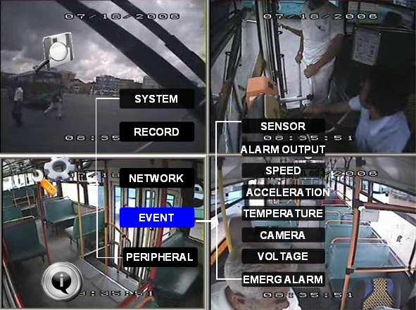
41 6.4 EVENT 41

42 6.4.1 SENSOR M-X3-V35 SVT 3 series MDVR can support 8 sensor inputs. EN: Enable, to active this sensor NAME: Press ENTER on the Name field to display the soft keyboard. Enter the text name to identify the source of each Sensor connected to the unit. OSD: Input the numbers and Characters, they will be shown on screen when alarms happen, and the alarm information will be embedded into the video file. Please press Enter into the soft keyboard. The label also identifies the type of event when doing a quick search using EVENT SEARCH option. SET: LOW (normal close) means low voltage can trigger alarm. HIGH (normal open) means high voltage can trigger alarm. ALARM: Press ENTER to select between OFF or ON: ON means when sensor triggered, alarm LED will flashing, until re-login the system with account, the flashing will disappear. LOCK: When LOCK is set ON, the video file will not be covered during the over-write process of hard disk; If switch/alarm/lock all set as ON, When sensor triggered, it will trigger alarm signal and event log, it will also trigger alarm recording and event recording. NEXT PAGE: Sensor trigger action means setup the alarm linkage for each sensor, for example, you setup the ch1 as the alarm linkage for sensor1, when sensor1 triggered, ch1 will change to full screen. And the device will response the trigger by PRI, sensor1 has the highest priority, sensor8 has the lowest priority. 42


43 6.4.2 SENSOR OUTPUT Our MDVR support 2 sensor outputs, two sensor outputs are on the I/O HUB. All the alarm inputs can trigger the three sensor output, such as sensor1~8, over speed, temperature, video loss and so on, please enter into GUI>>>>SETUP>>>EVENT>>>SENSOR OUTPUT, as follow: 43


44 ON means this input can trigger this out put, OFF means can t SPEED Setup the alarm for over speed and some other parameters. SOURCE: MDVR is capable of capturing vehicle speed via GPS antenna or Vehicle--speedometer. Browse between the settings of GPS or speedometer from the list. Please note that the GPS antenna should be connected to MDVR to receive satellite signals for speed. For more information on capturing speed from speedometer please contact local distributor for more technical support; CALIBRATE: Speed check is used to calibrate the offset speed when connected to the speedometer. That s to say, the check only available when speed source is vehicle. Input the first area with the vehicle speed, for example at 80 (in KM/H) 44
 set as first area data (80); OVER SPEED: If the vehicle exceeds the SPD, MDVR will trigger the alarm signal (when the following")
45 Start the vehicle and the second area will show the data from speedometer (in HZ) When the vehicle reach to 80 KM/H (shown in vehicle meter or dash board), and keep this speed at 30 seconds, then press the Check to make the system calibrate the second area (HZ) set as first area data (80); OVER SPEED: If the vehicle exceeds the SPD, MDVR will trigger the alarm signal (when the following option ALARM set as YES) until the driver slows down the speed LOW SPEED: If the vehicle exceeds the high speed limit, MDVR will trigger the alarm signal (when the following option ALARM set as YES) until the Admin password is entered to acknowledge the alarm. OSD: To name the event, for example we can name the over speed event as SPDH, and low speed as SPDL. Whenever the event triggers, SPDH or SPDL will show in OSD. EN: To enable the alarm when this kind of event triggers. Threshold: The threshold we define for the speed. For example, if we define 80MPH as low speed, once the speed equals or lower than this amount, it would be reckon as an alarm file. ALARM: To enable the flashing LED when the speed alarm is triggered. LOCK: To lock the speed alarm files so that it could be covered during the process of over-writing ACCELERATION There are 3 values for G force inertial sensor: X, Y, and Z. X indicate forward and backward. X, Y indicates left and right and Z indicated up and down. Threshold is the limitation for the value, if the value large than the setting in the menu, then MDVR will alarm. This function only can be active when the MDVR connected with inertial sensor. 45


46 6.4.5 TEMPERATURE M-X3-V35 Inspection for temperature, there are high and low two kinds temperature inspection. If the MDVR working temperature is higher than the threshold for HIGH TEMP, MDVRwillalarm. If the MDVR working temperature is lower than the threshold for LOW TEMP, MDVR will alarm. HDD heating is to enable the heating function so that MDVR could work normally under the temperature below CAMERA Display the alarm information from camera. MOTION DETECTION SETTING: This is to set the Channel which will be used for motion detection and the channel for blind detection, sensitivity, and sensitive area. OSD: This to name the alarms caused by different kinds of camera triggers. For example, MD for motion detection, BD for blind detection and VL for video loss. EN: To enable the switch for MD, BD and VL alarms. ALARM: This is to open the alarm trigger. Lock: To lock the alarm files caused by MD/ BD/ VL or not. 46


47 6.4.7 VOLTAGE M-X3-V35 LOW VOLTAGE PROTECTION: means when the voltage is in a low status, MDVR will disconnect to CMS or shut down automatically. ENABLE: setup the voltage protection switch, ON means enable, OFF means disable. LOW VOLTAGE: setup the low Voltage limited value for MDVR to shut down. VOLTAGE OF START: setup the voltage parameter for MDVR to reboot up. TIME FOR SHUTDOWN: means when MDVR in low voltage for so long time, device will shutdown automatically. INTERVAL TIME FOR CMS: means when MDVR in low voltage for such a period, device will disconnect to CMS server ALARM FOR PANIC BUTTON: This is to set the panic button alarm files. 47

48 6.5 PERIPHERAL M-X3-V PTZ CHANNEL: The channel of PTZ connected. PROTOCOL: select the protocol of different PTZ, there are two protocols to switch, and the default is Pelco-D BAUD RATE: select the different baud rate for your PTZ, there are 1200, 2400, 4800, and 9600 DATA BIT: there are 5,6,7,8 options to select, default setting is 8. STOP BIT: there are 1and 2 to select, the default setting is 1. VERIFY: there are None/Odd/Even/Mark/Space to select, the default setting is none. ADDRESS: Fill the code of respective PTZ 48


49 6.5.2 EXT.COM SETUP This interface is for external accessory connection, such as control pane, PTZ, Inertia sensor, LED screen, station announcement and so on. MODE: There are STANDARD and BUS MODE two options, when select standard mode, you can select each external port for each COM, when select Bus mode, COM1 is station announcement, COM2 is amplifier board, unchangeable, COM3 and COM4 is changeable. 49


50 7INFORMATION SYSTEM Display the MCU version, firmware version, hard disk information. 1, NONE HDD means No HDD installed or the HDD is defective and can not work. 2, NO FORMAT means HDD installed but not formatted. 3, showing the detailed information for HDD means HDD works fine. 50


51 7.1.2 HISTORY M-X3-V35 The data for history information Press CLEAR to delete all the current data MODULES Display the module information (GPS and WIFI) 51

52 52 M-X3-V35
User Manual Ness IQ-MDVR-4 GUI. Mobile Digital Video Recorder
 Ness IQ-MDVR-4 GUI Mobile Digital Video Recorder NOTICE The information in this manual was current when published. The manufacturer reserves the right to revise and improve its products. All specifications
User Manual Ness IQ-MDVR-8 GUI. Mobile Digital Video Recorder
 User Manual Ness IQ-MDVR-8 GUI Mobile Digital Video Recorder NOTICE The information in this manual was current when published. The manufacturer reserves the right to revise and improve its products. All
MVR-704 4CH Mobile DVR User s Manual
 MVR-704 4CH Mobile DVR User s Manual 2014 www.vipro.com.tw Mobile DVR MVR-704 NOTICE 2 NOTICE The purpose of this manual is to kindly aid the user for the operation for our MDVR (especially for GUI setting).
NOTICE. Copyright. More Information 1. ICS-MDVR-400 Series
 NOTICE The information in this manual was current when published. The manufacturer reserves the right to revise and improve its products. All specifications are therefore subject to change without any
NOTICE. Copyright. More Information 1. ICS-MDVR-800 Series
 NOTICE The information in this manual was current when published. The manufacturer reserves the right to revise and improve its products. All specifications are therefore subject to change without any
User Manual For DVR MOBILE MD805. Mobile Digital Video Recorder
 User Manual For DVR MOBILE MD805 Mobile Digital Video Recorder NOTICE The information in this manual was current when published. The manufacturer reserves the right to revise and improve its products.
Contents LOCAL MANAGEMENT LOGIN INTERFACE RECORD SEARCH: LOG SEARCH SYSTEM STATUS BASIC SETUP.
 User Manual For MD AHD MDVR Copyright 2013-2016, Howen Technology Co., Ltd All Rights Reserved 1-59 Contents 1. 2. LOCAL MANAGEMENT... 3 2.1. LOGIN INTERFACE... 3 2.2. RECORD SEARCH:...6 2.3. LOG SEARCH...
H.264 Network DVR. Quick Start. GUI Display with USB Mouse Control 336Z
 336Z H.264 Network DVR Quick Start GUI Display with USB Mouse Control Please read instructions thoroughly before operation and retain it for future reference. For the actual display & operation, please
4CH MOBILE DVR OPERATING INSTRUCTIONS
 4CH MOBILE DVR OPERATING INSTRUCTIONS Before operating this set, please read these instructions completely The DVR needs to use SD card from Brand SAN DISK, the reading and Writing speed needs to reach
H.264 Network DVR. Quick Start
 341Z H.264 Network DVR Quick Start GUI Display with USB Mouse Control Please read instructions thoroughly before operation and retain it for future reference. For the actual display & operation, please
H.264 Network DVR. Quick Start
 H.264 Network DVR Quick Start GUI Display with USB Mouse Control Please read instructions thoroughly before operation and retain it for future reference. For the actual display & operation, please refer
CONTENT. Part one -- 3G transmission MDVR setup Insert SIM card Register Info CHANNEL SETTINGS...
 CONTENT Part one -- 3G transmission... 1 1 MDVR setup... 1 1.1 Insert SIM card... 1 1.2 Register Info... 2 1.3 CHANNEL SETTINGS... 2 1.4 SUB-STREAM... 3 1.5 SERVER NETWORK... 5 1.6 MOBILE NETWORK... 6
DVR RANGE ENGINEER MANUAL
 INSPIRE DVR RANGE ENGINEER MANUAL Contents Hardware Inspire DVR range Connections Connecting a mouse Connecting keyboard Connecting PTZ cameras Connecting Keyboard/PTZ Alarm connections Using front panel
User s Manual of DVR ULTIMAX. Remote Client Software V wersja 2.40
 User s Manual of DVR ULTIMAX Remote Client Software V 4.0.1 ULTIMAX-304 ULTIMAX-308 ULTIMAX-316 ULTIMAX-504 ULTIMAX-508 ULTIMAX-516 ULTIMAX-704 ULTIMAX-708 ULTIMAX-716 wersja 2.40 Index 1 Software Install,
Chapter 1 Features FEATURES
 Chapter 1 Features Operation Playback, recording and network transmission simultaneously Real time full screen or quad screen display 2X digital zoom and Picture-in-picture display Easy operations by shuttle
VMS-A1 Client Software. User Manual
 VMS-A1 Client Software User Manual Contents Contents... 2 Chapter1. Overview... 4 1.1 Description... 4 1.2 Features & Functions... 4 Chapter2. Update Info... 6 Chapter3. Starting VMS-A1... 7 3.1 Installing
JVS-D7216 Standalone DVR User Manual
 Menu JVS-D7216 Standalone DVR User Manual JVS-D7216 Standalone DVR Instructions 1. Introduction..4 1.1 Product Description...4 1.2 Features..4 1.3 Specifications...4 2. Product Features....6 2.1 Panel
MOSS-DVR-810 Mobile Digital SD Recorder User Manual
 MOSS-DVR-810 Mobile Digital SD Recorder User Manual Before installing and using, be sure to read this Manual for best performance. ATTENTION This product is to be used within the vehicle interior. In order
Brand. E42 / E82 DVR System User Manual
 Brand E42 / E82 DVR System User Manual 1 Safety precautions Before using the product, please ensure that you read the safety precautions described below. Always ensure that the product is used correctly.
HLong Asia Industrial
 SDI DVR Stand alone digital video recorder HLong Asia Industrial Thank you for using the company's products! This manual describes only the host functions basic operation. Product design and specification
Lorex Client 7.0 & Lorex Message Master
 Lorex Client 7.0 & Lorex Message Master Software Manual English Version 1.0 MODELS: L19WD Series www.lorexcctv.com Includes L19WD800 & L19WD1600 Copyright 2008 Lorex Technology Inc. Table of Contents Table
QSD2308L/QSD2316L DVR User s Manual
 QSD2308L/QSD2316L DVR User s Manual NOTE: We use two different front panel designs on these models. They have the same function buttons but they are arranged differently. Please match the front panel on
USER MANUAL. Mac Version
 USER MANUAL Mac Version Contents 1 Software Introduction... 1 1.1 Summary... 1 1.2 Install and Uninstall... 1 1.2.1 Install the Software... 1 2 Login Software... 3 2.1 Login... 3 2.2 Control Panel Instruction...
Pro71600N3 NVR User Manual
 Pro71600N3 NVR User Manual User Information Admin User Name: Admin Password: IP Address: System Name: Table Of Contents 1. Menu Operation...4 1.1 Main Menu...4 2. Start & Shutdown System...5 2.1 Start
Mobile Digital Video Recorder with Advertisement/ Multimedia Playback Instruction Manual
 Mobile Digital Video Recorder with Advertisement/ Multimedia Playback Instruction Manual Copyright c 2005-2006 All Rights Reserved TABLE OF CONTENTS Section Page I. Product Components and Features 3 II.
CONTENTS Chapter 1: DVR Features... 4 Chapter 2: Overview... 5 Chapter 3: Starting the DVR... 8
 1 CONTENTS Chapter 1: DVR Features... 4 Chapter 2: Overview... 5 2.1 Front Panel... 5 2.2 Rear Panel... 6 2.3 Remote Control... 7 Chapter 3: Starting the DVR... 8 3.1 Firmware Version... 8 3.2 Detecting
4CH SD Card Mobile DVR Operation manual. Content
 DVR instruction 4CH SD Card Mobile DVR Operation manual Content Power connection--------------------------------------------------------------------------------------4 Remote controller instruction----------------------------------------------------------------------6
Pro7804N1 NVR User Manual
 Pro7804N1 NVR User Manual Pro7804N1 User Manual BW R6.indd 1 User Information Admin User Name: Admin Password: IP Address: System Name: Table Of Contents 1. Menu Operation...4 1.1 Main Menu...4 2. Start
DS-8100HMFI-TH Series Mobile DVR. Quick Operation Guide. Version 2.2.0
 DS-8100HMFI-TH Series Mobile DVR Quick Operation Guide Version 2.2.0 Quick Operation Guide of DS-8100HMFI-TH Series Mobile DVR i Thank you for purchasing our product. This manual applies to DS-8100HMFI-TH
NVMS User Manual
 NVMS-1000 User Manual Contents 1 Software Introduction...1 1.1 Summary... 1 1.2 Operation Environment... 1 1.3 Install and Uninstall... 2 1.3.1 Install the Software... 2 1.3.2 Uninstall the Software...
OBSERVER 4000 USER GUIDE
 OBSERVER 4000 USER GUIDE OBSERVER 4000 USER GUIDE Important Notices Title: Observer 4000 User Guide Document Version: 1.0 Firmware version: X01-4-T570721 Safety Vision attempts to provide information contained
Analog High Definition DVR. Stand alone digital video recorder. User Manual H.264 AHD DVR
 Analog High Definition DVR Stand alone digital video recorder User Manual H.264 AHD DVR WARNING To reduce the risk of fire or electric shock, do not expose this appliance to rain or moisture. All the safety
NVMS1000. User Manual
 NVMS1000 User Manual Contents 1 Software Introduction... 1 1.1 Summary... 1 1.2 Operation Environment... 1 1.3 Install and Uninstall... 2 1.3.1 Install the Software... 2 1.3.2 Uninstall the Software...
Quick Start. H.264 Network DVR 303Z
 303Z H.264 Network DVR Quick Start Please read instructions thoroughly before operation and retain it for future reference. The image shown above may differ from the actual product appearance. 792_Quick_V0.9
User Manual. For. CMS (WEB version)
") User Manual For CMS (WEB version) Contents 1 Preface...1 1.1 System requirements... 1 1.2 Main features... 2 2 Server Installation...3 2.1 System requirement... 3 2.2 Installation... 4 2.2.1 Complete...5
User Manual For CMS (WEB version) Contents 1 Preface...1 1.1 System requirements... 1 1.2 Main features... 2 2 Server Installation...3 2.1 System requirement... 3 2.2 Installation... 4 2.2.1 Complete...5
CAMERAS IP START SERIES
 CAMERAS IP START SERIES Contents 1. Login Interface... 3 2. Preview... 4 2.1 Open/Close Preview... 5 2.2 Full-screen Preview... 5 2.3 Electronic Zoom-in... 5 2.3 PTZ Control... 6 3. File Management...
SecureShot HC Quick Start Instruction Page
 SecureShot HC Quick Start Instruction Page Your new SecurShot HC has been factory pre-programmed and tested to fit most applications. It is ready-to-go right out of the box. An SD card is installed, and
Triplex MPEG-4 DVR. OSD Setup Guide
 Triplex MPEG-4 DVR OSD Setup Guide 00940A01 Version 1.1 00940A01 Table of Content Menu System Overview...5 ...5 Key Usage in OSD Menu...5 Key Usage in Virtual Keyboard...6 System Setup...8 ...8
PIVOT CMS CLIENT SOFTWARE USER MANUAL
 PIVOT CMS CLIENT SOFTWARE USER MANUAL 1 CMS USER GUIDE 1.1 PC REQUIREMENT Recommended PC Requirement OS CPU VGA RAM HDD Graphics Card OS CPU VGA RAM HDD Windows Vista, 7 or higher Intel Core2Quad Q9400
Configuring and Managing the IP Camera
 CHAPTER 3 The Cisco Video Surveillance IP Camera provides configuration windows that you use to configure and manage the IP camera. This chapter explains how to access the configuration windows, describes
Digital Video Recorder User Manual. DVR User Manual. For H channe/ 8-channel/16-channel Digital Video Recorder All rights reserved
 DVR User Manual For H.264-4-channe/ 8-channel/16-channel Digital Video Recorder All rights reserved i CAUTION Please read this user manual carefully to ensure that you can use the device correctly and
Stand Alone Type. Digital Video Recorder USER S MANUAL. XRS 1000 Series. This manual is written based on 1016
 Stand Alone Type Digital Video Recorder USER S MANUAL XRS 1000 Series This manual is written based on 1016 Index CHAPTER 1 Specification & System organization 1. Product Contents List --------------------------------------------------------
NVR User Manual. NVR User Manual For further help, please visit
 NVR User Manual NVR User Manual For further help, please visit www.zmodo.com Introduction This product series is a 4 channel embedded NVR with pentaplex functionality: the product will perform video audio
NVMS1000. User Manual
 NVMS1000 User Manual Contents 1 Software Introduction... 1 1.1 Summary... 1 1.2 Operation Environment... 1 1.3 Install and Uninstall... 2 1.3.1 Install the Software... 2 1.3.2 Uninstall the Software...
Motion Activated Hidden Video Recording System Manual Patent No. M P/N: F40072B01
 SleuthGear Recluse Contents Package Contains... 2 Quick Setup... 3 How to open Motion Activated Black Box... 3 Interface... 4 LED Indicator status... 4 Installation... 5 1. How to open battery cover...
4 Channel Digital Video Recorder / Camera Kit. Model No QV-3024 USER S MANUAL
 4 Channel Digital Video Recorder / Camera Kit Model No QV-3024 USER S MANUAL 1 Important Note: Please keep this manual in a safe location in case you need to refer to it at a later date. 1 INDEX CHAPTER
SPY-DVR4HYB & SPY-DVR8HYB SPY-DVR4HYB2ND & SPY-DVR8HYB2ND
 SPY-DVR4HYB & SPY-DVR8HYB SPY-DVR4HYB2ND & SPY-DVR8HYB2ND Instructions 1.0 INTRODUCTION 1.1 Main menu 2.0 SPLIT SCREEN 3.0 SYSTEM SETUP 3.1 General Setup 3.2 Time Setup 3.3 HDD Setup 3.4 Screen Setup 3.5
Mobile DVR (MDR) User Manual
 User Manual") Mobile DVR (MDR) User Manual 1 1. Overview 1.1 Introduction Mobile DVR adopt highly integrated H.264 ASIC, using the SD card or hard disk as a video storage medium. The system is with strong anti-vibration
Mobile DVR (MDR) User Manual 1 1. Overview 1.1 Introduction Mobile DVR adopt highly integrated H.264 ASIC, using the SD card or hard disk as a video storage medium. The system is with strong anti-vibration
NVMS User Manual
 NVMS-1000 User Manual Contents 1 Software Introduction...1 1.1 Summary... 1 1.2 Operation Environment... 1 1.3 Install and Uninstall... 2 1.3.1 Install the Software... 2 1.3.2 Uninstall the Software...
Ventra XDR-450/H Mobile DVR Software Manual
 Ventra XDR-450/H Mobile DVR Software Manual 5CH Hybrid Mobile DVR This manual is only for the XDR software. For Hardware manual, please refer to XDR User Guide Ventra Technology Inc www.ventrainc.com info@ventrainc.com
Error! Bookmark not defined.
 HD-NVR user manual Directory Part one Basic Operation... 3 1. Basic Installation... 3 1.1 Hard Disk Installation... 3 1.2 Mouse Connection... 3 2. Starting... 3 3.Turn Off... 3 4.Login... 4 5.Preview...
Pro7400H1 Hybrid DVR User Manual
 Pro7400H1 Hybrid DVR User Manual User Information Admin User Name: Admin Password: IP Address: System Name: Table Of Contents 1. Menu Operation... 4 1.1 Main Menu... 4 2. Start Up/Shutdown System... 5
NVMS User Manual. Version 2.1.0
 NVMS-1000 User Manual Version 2.1.0 Contents 1 Software Introduction... 1 1.1 Summary... 1 1.2 Operation Environment... 1 1.3 Install and Uninstall... 2 1.3.1 Install the Software... 2 1.3.2 Uninstall
4CH Real Time DVR. User Guide INFORMATION MAY CHANGE WITHOUT NOTICE. Digital Video Recorder
 User Guide INFORMATION MAY CHANGE WITHOUT NOTICE. Table of Contents Caution... 4 Package Contents... 4 Introduction... 5 1. Product Overview...5 2. Front Panel...5 3. Rear Panel...6 4. IR Remote Controller
BlackHawk for MAC Software User Guide
 BlackHawk for MAC Software User Guide Products: BLK-DH2 Series and BLK-HD Series DVRs Please read this manual before using your software, and always follow the instructions for safety and proper use. Save
NVR&IPCAM USER MANUAL V1.0 (USER MANUAL) V1.0. Thanks for choosing our products, please read this manual carefully before use!
 V1.0. Thanks for choosing our products, please read this manual carefully before use!") NVR&IPCAM (USER MANUAL) V1.0 Thanks for choosing our products, please read this manual carefully before use! NOTICE Installation condition 1) In order to ensure your rights, please read this manual carefully
NVR&IPCAM (USER MANUAL) V1.0 Thanks for choosing our products, please read this manual carefully before use! NOTICE Installation condition 1) In order to ensure your rights, please read this manual carefully
Digital Video Recorder User Manual. DVR User Manual. For H channel/ 8-channel/16-channel Digital Video Recorder All rights reserved
 DVR User Manual For H.264-4-channel/ 8-channel/16-channel Digital Video Recorder All rights reserved i CAUTION ii Please read this user manual carefully to ensure that you can use the device correctly
HD IPCameras User's Mannual
 Thank you for purchasing our products, if you have any questions or need, please feel free to contact us. This manual applies to IPC-XXX series of network cameras. This manual may contain technical inaccuracies
261Z. DR040_Quick_V1.0 PLAY RE C
 261Z MPEG4 4CH DVR Quick Guide REC PLAY PA USE ST OP REW FF HDD HD D Fu ll ALAR M TIMER PLAY RE C MENU ENTER LIST SLOW ZOOM SEQ Please read instructions thoroughly before operation and retain it for future
DVR User s Manual. For H FPS /8-channel digital video recorder All rights reserved. Rev
 QSDT8DP DVR User s Manual For H.264-240 FPS /8-channel digital video recorder All rights reserved Rev 120209 i QSDT8DP User s Manual CAUTION Please read this user manual carefully to ensure that you can
NEXT Mobile Video Tracking
 NEXT Mobile Video Tracking *Your vehicle picks up unwanted passengers from alongside the road * you can t view live footage while your vehicle going cross border *fuel is illegally siphoned from your vehicles
Tektronix Technology System LLC. Model no. Tk1001z Version no. V1.0. Specification. Revision History
 Document name Specification Document no. TK-11001Z Specification Product Name:HDD Mobile DVR Product Model:tk1001z Version:V1.0 Revision History Revision Date Revised by Version Revision Content Approved
Notice The information in this manual was current when published. The manufacturer reserves the right to revise and improve its products. All specific
 MDHB3204 User Manual Hybrid Mobile Digital Recorder Copyright 2016-2017, IOT Smart Solutions, LLC All Rights Reserved 1-70 Notice The information in this manual was current when published. The manufacturer
4 CH Vehicle Mobile DVR
 4 CH Vehicle Mobile DVR TAYPE A: Without 3G Module TAYPE B: 3G Module 2012 APR V1.1 TAYPE B OPTIONAL Index A. Features... 1 B. Specification... 2 C. Product Appearance... 3 D. Installation 2.5 HDD... 4
A. Features 1. Suitable for all personal vehicles, taxi, buses, trucks and etc. 2. Easy to install and compact size to prevent blocking the driver's
 Index A. Features... 1 B. Specifications... 2 C. Product Appearance... 3 D. Product Dimensions... 4 E. Installation Instructions... 5 F. Start / Stop Recording... 6 G. Playback... 8 1. Onsite Playback...
Client Software-4000(V ) User Manual
 User Manual") Client Software-4000(V2.00.02) User Manual Index Chapter 1 Welcome to Client Software-4000 (V2.0)... 1 1.1 Overview... 1 1.2 Computer Disposition Request... 1 1.3 Convention... 1 Chapter 2 Install & Uninstall...
Client Software-4000(V2.00.02) User Manual Index Chapter 1 Welcome to Client Software-4000 (V2.0)... 1 1.1 Overview... 1 1.2 Computer Disposition Request... 1 1.3 Convention... 1 Chapter 2 Install & Uninstall...
JZTEK DVR Operation Manual
 Dear Valued Client, JZTEK DVR Operation Manual Thank you for your trust about JZTEK! If you re satisfied with this JZTEK product, we would sincerely appreciate providing your positive review and feedback
4CH H.264 Multiplex DVR
 4CH H.264 Multiplex DVR User Manual VER.:1.0, P/N: R040199A This symbol is intended to alert the user to the presence of unprotected Dangerous voltage" within the product's enclosure that may be strong
errors, or places that do not match the product. If you have any unsolved please contact our technical support department.
 - 0 - Statement: This manual may contain several technical inaccuracies or typographical errors, or places that do not match the product. If you have any unsolved problems in the process of using product
Quick Start Guide 4/8/16-CH DVR.
 Quick Start Guide 4/8/16-CH DVR 1. Install Hard Drive &DVD Writer 1.1 Install Hard Drive Notice: 1. Support two SATA hard drives. Please use the hard drive the manufacturers recommend specially for security
Video Management Software
 Video Management Software User Manual Web: europesecurity.eu Mail: info@europesecurity.eu Tel.: 0541 352 952 User s Manual 2 Contents CHAPTER : XMS CENTRAL USER MANUAL 1 PC REQUIREMENT 3 2 INSTALL 3 3
DS-9000 Series Hybrid Net DVR
 DS-9000 Series Hybrid Net DVR Overview DS-9000 series net DVR is the Hybrid DVR of a new generation designed by HIKVISION. The product combines various patents, along with advanced IT technologies such
RemoteManager Software
 RMS RemoteManager Software User Manual Contents of this user manual are protected under copyrights and computer program laws. Functions or configurations are subject to be changed or modified without prior
DVR CH Digital Video Recorder SW242-LP4 / SW242-LPN
 DVR4-1100 4CH Digital Video Recorder SW242-LP4 / SW242-LPN User Manual INDEX 1. DVR Features... 1 2. Layout 2.1 Front Panel...1 2.2 Rear Panel...2 2.3 Remote Controller...2 3. Installation 3.1 Installing
ICOP PRO USER GUIDE. Important Notices. Title: ICOP PRO User Guide Document Version: 2.1. Firmware Version: X15-4-T521082
 ICOP PRO USER GUIDE ICOP PRO USER GUIDE Important Notices Title: ICOP PRO User Guide Document Version: 2.1 Firmware Version: X15-4-T521082 Safety Vision attempts to provide information contained in this
DVR User Manual. For H.264-4/8/16-channel digital video recorder All rights reserved
 DVR User Manual For H.264-4/8/16-channel digital video recorder All rights reserved CAUTION Please read this user manual carefully to ensure that you can use the device correctly and safely We do not warrant
ESS8 Mobile 8-Channel Digital Video Recorder
 ESS8 Mobile 8-Channel Digital Video Recorder USER GUIDE Copyright 2015-2016, Robotics Technologies, Inc. All rights reserved. Table of Contents 1.0 Introduction...3 1.1 Installation Environment...3 2.0
WEB GUI User manual Web Operation Guide ISSUE V2.0 DATE
 ZN8 Series WEB GUI User manual ISSUE V2.0 DATE 2016-02-22 About This Document About This Document Purpose This document describes how to use the web management system, including network access, network
QSTD2404/QSTD2408/QSTD2416 Digital Video Recorders User s Manual
 QSTD2400 Series DVR User s Manual QSTD2404/QSTD2408/QSTD2416 Digital Video Recorders User s Manual For H.264-4-channel/ 8-channel/16-channel Digital Video Recorders All rights reserved Rev 091708 i QSTD2400
IPC Online Operation Manual
 IPC Online Operation Manual 1 Overview An IP camera (hereinafter referred to as IPC) is a new product integrating network video technologies into a traditional camera. The IPC can realize simpler monitoring
DDNS UPNP
 PL-ADR0608/16-H2 PL-ADR0604-H2 Content 1 Product Introduction... 3 2 Installation... 3 2.1 Open-package Inspection... 3 2.2 Hard Disk Installation... 3 3. Local operation guide... 3 3.1 Boot operation...
Triplex MPEG-4 DVR. OSD Setup Guide
 Triplex MPEG-4 DVR OSD Setup Guide 79100A03 Version 1.3 79100A03 Table of Content Menu System Overview...5 ...5 Key Usage in OSD Menu...5 Key Usage in Virtual Keyboard...6 System Setup...7 ...7
Before Setting. GMS is an integrated security management system that provides a useful solution for central monitoring station operation.
 GMS MANUAL Before Setting What What is is GMS? GMS? GMS is an integrated security management system that provides a useful solution for central monitoring station operation. Minimum Minimum System System
DS-9000 Series Hybrid DVR
 DS-9000 Series Hybrid DVR Overview DS-9000 series DVR is the Hybrid DVR of a new generation designed by HIKVISION. The product combines various patents, along with advanced IT technologies such as video
SURVEILLANCE KIT USER MANUAL. All in One Series
 SURVEILLANCE KIT USER MANUAL All in One Series Contents Part one Basic Operation 1 1. Basic Installation 1 1. Hard Disk Installation 1 2. Mouse Connection 1 2. Starting 1 3. Turn Off 1 4. Login 2 5. Preview
DHE-04 DHE-08 DHE H H.264 DVR 4 / 8 / 16 CH. Quick Setup Guide PACKAGE CONTENTS A. B. C. D. E. F. G. H. Inside the DVR I.
 960H H.264 DVR 4 / 8 / 16 CH. Quick Setup Guide DHE-04 DHE-08 DHE-16 PACKAGE CONTENTS A. One (1) DHE-04 / DHE-08 / DHE-16 DVR B. One (1) Remote Controller C. Two (2) AAA Battery for Remote Controller D.
JZTEK DVR Operation Manual
 JZTEK DVR Operation Manual Dear Valued Client, Windows10 version Thank you for your trust about JZTEK! If you re satisfied with this JZTEK product, we would sincerely appreciate providing your positive
Downloaded from manuals search engine
 INDEX 1. DVR Features...1 2. Layout 2.1 Front Panel...1 2.2 Rear Panel...2 2.3 Remote Control...2 3. Installation 3.1 Installing the Hard Drive...3 3.2 Connecting Camera and Monitor...3 3.3 Connecting
Tektronix Technology System LLC Document name Specification Document no. TK-11002Z. Model no. Tk1002z Version no. V1.0.
 Document name Specification Document no. TK-11002Z Specification Product Name:HDD Mobile DVR Product Model -tk1002z Version:V1.0 Revision History Revision Date Revised by Version Revision Content Approved
Chapter 1: Introduction
 Contents Chapter 1 - Introduction... 2 1.1 General Description... 2 1.2 Technical Parameters... 2 1.3 Checking Before Use & HDD Installation... 2 Chapter 2 Front/Rear Panels and Remote Control... 3 2.1
DS-7204HVI-ST Series DVR. Technical Manual
 DS-7204HVI-ST Series DVR Technical Manual Notices The information in this documentation is subject to change without notice and does not represent any commitment on behalf of HIKVISION. HIKVISION disclaims
DS-1100KI Network Keyboard User Manual V 2.1.0
 DS-1100KI Network Keyboard User Manual V 2.1.0 (V2.0) Preventive and Cautionary Tips Before connecting and operating your keyboard, please be advised of the following tips: Ensure unit is placed in a well-ventilated,
DDR-08 DDR-16 Full D1 Realtime H.264 DVR 8 / 16 CH. Quick Setup Guide
 DDR-08 DDR-16 Full D1 Realtime H.264 DVR 8 / 16 CH. Quick Setup Guide PACKAGE CONTENTS A. One (1) DDR-08 / DDR-16 DVR B. One (1) Remote Controller C. Two (2) AAA Battery for Remote Controller D. One (1)
HD All-in-one DVR. User manual
 HD All-in-one DVR User manual Table of Contents 1. Product Introduction.. 2 1.1 Product Summary... 2 1.2 Parameters... 2 2. Product Outside Structure Introduction... 4 2.1 The Panel Instruction... 4 2.2
4CH/ 8CH/ 16CH Digital Video Recorder
 4CH/ 8CH/ 16CH Digital Video Recorder DVR204B/ 208B/ 216B INSTRUCTION MANUAL DIRECTORY CHAPTER 1 Hard Disk Installing (Standard shipping products include neither HDD or R/W)...2 CHAPTER 2 Panel Appearance...4
SNMP Web Management. User s Manual
 SNMP Web Management User s Manual Suitable Product: SNMP Web Card SNMP Web Box Management Software for Uninterruptible Power Supply Systems Table of Contents 1. Overview... 1 1.1 Introduction... 1 1.2
SDI Digital Video Recorder. Quick Operation Guide
 SDI Digital Video Recorder Quick Operation Guide Thank you for purchasing our product. If there is any question or request, please do not hesitate to contact dealer. This manual is applicable to HDDVRXXXX-SDI
DS-8100HCI-ST Series DVR. Technical Manual
 DS-8100HCI-ST Series DVR Technical Manual Notices The information in this documentation is subject to change without notice and does not represent any commitment on behalf of HIKVISION. HIKVISION disclaims
Specifications of Mobile DVR VP 5004
 Specifications of Mobile DVR VP 5004 Model Name Video Input VP-5004 Video BNC input x 4 *CHANGEABLE / CUSTOMIZED AVAILABLE* Note: VP-5004 also supports IP Camera over Cat5 cable. Please contact our sales
R4, R8, R16 Digital Video Recorders Quick Setup Guide
 R4, R8, R16 Digital Video Recorders Quick Setup Guide This guide provides instructions to initially setup the R16 (16 channel) digital video recorders (DVR). The DVR supports these advanced features: 2