ION. User Manual Rev
|
|
|
- Abigayle Smith
- 6 years ago
- Views:
Transcription


1 ION User Manual Rev
2 Document Revision History Rev Number Description Original document release Weather radar added Video playback functionality enhancements/additions Added audio setup recommendations and change tracking (black lines in margin) Page/ Section -- Sec 4 Sec 3 -- Date JAN 2016 JAN 2016 FEB 2016 JUN 2016 Churchill Navigation Support Phone: support@churchillnavigation.com 2
3 Table of Contents Introduction... 4 Section 1: Technical Characteristics & Specifications... 5 Section 2: Operation... 8 Section 3 Playback Section 4 Weather Radar Display Section 5 Camera Link Section 6 Setup Menu Section 7 Troubleshooting Churchill Navigation Support Phone: support@churchillnavigation.com 3
4 Introduction Thank you for purchasing the Churchill Navigation ION video recorder. With a flexible configuration and assortment of pre-programmed modules (plus the ability to develop your own), coupled with an easyto-use user interface, the ION is ready to solve any video-related challenge you may have. This manual provides detailed information on the technical specifications and characteristics as well as the operation of your ION video recorder.! Warning The information contained in this document is considered confidential and proprietary to Churchill Navigation. Neither the document nor the information contained therein should be disclosed or reproduced in whole or in part, without express written consent of Churchill Navigation. Changes or modifications not expressly approved by Churchill Navigation could void the user s authority to operate the equipment.! Caution The ION s display is coated with a special anti-reflective, NVIS-compatible coating that is very sensitive to waxes and abrasive cleaners. DO NOT USE CLEANERS CONTAINING AMMONIA. To correctly clean the display, use a clean, lint-free microfiber cloth and/or an avionics or eye-glass cleaning product that is safe for anti-reflective coatings. Non-Churchill Navigation part numbers referenced in this manual are not maintained by Churchill Navigation and may be subject to change without notice. Note All information including technical specifications and screenshots used in this guide are current at the time of publication. All information depicted in this guide, including hardware and software names, versions, and part numbers, is subject to change and may not be up to date. Hardware Warranty The Churchill Navigation ION video recorder is warranted to be free of defects in workmanship or performance for three (3) years from date of installation by a Churchill Navigation dealer or installer. This hardware warranty covers all materials and labor but is exclusive of any costs incurred to deliver the defective unit to and from Churchill Navigation or its designated repair center, or any labor to remove the defective unit from the aircraft. Units that have been damaged or exhibit wear beyond reasonable use will not be considered for warranty repair. Contact Churchill Navigation for any questions regarding this warranty and/or for a return authorization for your ION. Churchill Navigation Support Phone: support@churchillnavigation.com 4

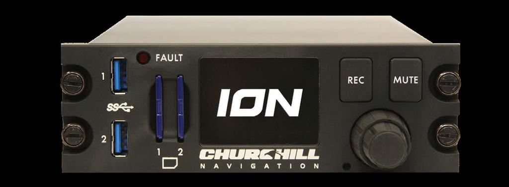
5 Section 1: Characteristics & Specifications Specifications 1.0 Description This section contains information concerning the physical characteristics and technical specifications of the Churchill Navigation ION video recorder. 1.1 Design Characteristics ION is a compact, solid-state DZUS mounted video recorder. ION offers simultaneous recording of two channels of HD-SDI video, one channel of analog video, audio and metadata along with a backlit, fullcolor LCD display. Video is recorded to removable USB or SD media for easy transport and hand-off. Users can also review recorded clips on the fly and perform playback while recording ) Backlit, full-color, 2.15 in [54.61 mm] diagonal LCD screen 2) REC button 3) Mute button 4) Control knob (inner knob, outer knob, and push-button operation) 5) SD media (2x) 6) USB 3.0 (2x) 7) Fault light Churchill Navigation Support Phone: support@churchillnavigation.com 5
6 1.2 Specifications Specifications Specification Product Designation/Description Churchill Navigation Part Number ION Video Recorder ION-xxxxxx Characteristic Physical Dimensions Weight Display type / dimensions / resolution Environmental Qualifications Operating Temperature Range Maximum Operating Altitude Power: Input Voltage Input Current Power consumption Circuit Breaker Requirement Connection Types, Protocols, and Standards Height at bezel: in [47.63 mm] Width at bezel: 5.75 in [ mm] Length (Enclosure depth): 7.0 in [177.8 mm] Overall depth, front knob to back of enclosure, excluding connectors: 8.32 in [ mm] 2.6 lbs ±.05 lbs [1.18 kg ±.02 kg] Backlit LCD, 2.15 in [54.61 mm] diagonal Native 320 x 240 pixel resolution NVIS Class A compliant / NVIS class B compatible DO-160 Qualified -20 C to +70 C +45,000 feet [+13,716m] 28VDC 4A on 28VDC (normal operating range) 112W (maximum) Minimum 7.5 amp rated LEMO (1x) J1 Power/GPIO LEMO (1x) J2 Ethernet LEMO (1x) J3 Misc. (USB, ARINC 429, Audio) LEMO (1x) J4 Serial port (RS232, RS422) BNC J5, J6, J7 HD-SDI 1 & HD-SDI 2 video in / HD-SDI video out BNC J8, J9, J10 Analog in Wi-Fi compatibility ac Churchill Navigation Support Phone: support@churchillnavigation.com 6
7 Video-in Support HD-SDI in channel 1 HD-SDI in channel 2 S-Video in Composite Video in (CVBS) Component Video in (YUV) Component Video in (RGB) Specifications Video-out Support Video-out Supported Resolutions Metadata Standard Video Recording Codec Audio-in Support Audio-out Support HD-SDI out 720p (50 fps) 720p (60 fps) 1080p (25 fps) 1080p (30 fps) 1080i (50 fps) 1080i (60 fps) KLV MISB/STANAG 4609 compliant H.264 (MPEG-4 AVC) H.265 (HEVC) MPEG-2 L/R channel in L/R channel out Churchill Navigation Support Phone: support@churchillnavigation.com 7


 during the recording.")
8 Section 2: Operation 2.0 Description This section contains instructions for the operation of the Churchill Navigation ION video recorder. 2.1 Powering the Unit On In most aircraft installations, the ION will be wired to a 28-volt DC aircraft power source and/or via a dedicated mission bus. In these cases, the ION will automatically start-up once power has been provided to the unit. Running the ION solely using aircraft battery power is not advised. Operation For non-aircraft installations, use the provided power cable connected to a standard 120 VAC outlet. The ION will start-up immediately once power is applied. If at any point in time the ION fails to properly boot or encounters a hardware error during the boot sequence, the fault light will illuminate. In this case, cycle power to the ION and attempt another restart. If, at that point in time, the ION still does not power-up and the fault light is still illuminated, please refer to the troubleshooting section of this manual. 2.2 Hardware The ION s hardware interface is streamlined for easy and intuitive operation. This eliminates navigating complex menus to perform basic tasks during time-critical missions. The ION features two hardwarebased buttons for quick access to recording and muting. Additionally, the dual concentric rotary encoder knob (referred to as control knob in this manual) provides access to all other internal menus, navigation within menus, and a center push-button for selection. Two hardware-based buttons provide the user with quick access to enable and disable recording (REC) and mute and un-mute audio (MUTE) during the recording. The control knob features an inner and outer section as well as a center push-button end. Typical operation uses the outer knob for coarse selection and navigation between major sections of the menu and the inner knob for fine selection within menus. To select an item, the user can press the pushbutton end of the knob as the enter command. [FIG 2.1] ION s hardware-based buttons: REC and MUTE buttons (top) and control knob with center push-button (bottom). Outer knob Inner knob Center pushbutton Churchill Navigation Support Phone: support@churchillnavigation.com 8

 with preferences for the type of encoder, video scaling, and metadata, plus global parameters like audio into a single entity.")
, the recorder s")
9 2.3 Basic Operation During basic operation, the outer control knob is used to select the desired recorder(s) from which video will be captured. By pressing the REC button, the user starts and stops the recording as desired. 2.4 Recorders In the ION, the term recorders is given to the recordable output made up of several different input parameters for any given video source. Recorders combine the video signal itself (analog or digital) with preferences for the type of encoder, video scaling, and metadata, plus global parameters like audio into a single entity. These settings and sources combine to become the HD-SDI-1, HD-SDI-2, and Analog recorders as shown below. Operation [FIG 2.2] Recorder selection screen In addition to the name, the recorder selection screen contains information about each recorder source including the status (recording / not recording), the recorder s assigned primary removable media location (SD 1, SD 2, USB 1, USB 2), and the amount of time remaining on the removable media Recorder Selection Screen The recorder selection screen displays an overview of the status of the recorders that have been setup in the ION. This screen is useful to get a general overview of the status of the recorder (either recording or not recording) and information about the removable media that has been assigned to each recorder. [FIG 2.3] Recorder selection screen detail The options available in the recorder selection screen will vary based on how the ION is configured and correspond to the various features the user may have purchased. Churchill Navigation Support Phone: support@churchillnavigation.com 9


 Expect to consume roughly 4GB per hour of recorded video SD Format as NTFS Class 4 (or better)")
![Expect to consume roughly 4GB per hour of recorded video [FIG 2.4] Removable media interfaces 2.5.](/docs-images/79/78842943/images/10-6.jpg "2 Recording HD-SDI Video When the ION is receiving either one or both HD-SDI recorder channels, use the outer")

10 2.5 Recording Video Removable Media Prior to recording, ensure that the ION has at least one available removable media device installed. Two USB and two SD ports are available for recording. Users can set the recording order preference for each recorder available in the ION. This option will also allow the ION to rollover to the next available drive when the current one becomes full. Operation Removable Media Recommendations: USB Format as NTFS USB 2.0 (or better) Expect to consume roughly 4GB per hour of recorded video SD Format as NTFS Class 4 (or better) Expect to consume roughly 4GB per hour of recorded video [FIG 2.4] Removable media interfaces Recording HD-SDI Video When the ION is receiving either one or both HD-SDI recorder channels, use the outer knob to select the desired recorder and press the REC button to start recording. Select the desired recorder with outer knob: HD-SDI 1 in this case. Press the REC button to start/stop the recording. [FIG 2.5] Recording operation Churchill Navigation Support Phone: support@churchillnavigation.com 10

11 Press the REC button once again to end the recording. Video files will be automatically saved to the recorder s preferred removable media location. The recorder selection screen will also provide an overview of any active recordings as well as the length of video that has been recorded. Operation [FIG 2.6] HD-SDI 1 recording in progress as viewed from the Recorder Selection Screen Recording Analog Video The ION s analog video recorder can be selected and recorded in an identical manner to the HD-SDI recorders operation. Use the outer knob to select the analog channel and press the REC button to start and stop the recording. [FIG 2.7] Hoist camera recording using analog video Note: Because the ION can accept several different types of analog video, setup is required for firsttime operation of a new ION. If you have connected analog video and still see a no signal screen or no analog channel is available, please refer to section 6.4.1(c) Analog video inputs and 7.2 Troubleshooting Analog Video. Churchill Navigation Support Phone: support@churchillnavigation.com 11


12 2.6 Audio Audio Setup For best audio quality, Churchill Navigation recommends that the ION audio input be connected to a balanced (chassis ground independent) output, with -15 dbv signal levels. It is also recommended to connect the ION audio input to a COM port, rather than a headset output. Please see the ION installation manual for addition setup detail. Operation The recommended ION audio setup has been tested on common aircraft audio control systems including the Eagle Copters USA (Geneva Aviation) G13000 Digital Audio Router and Technisonic A711 and A711X. If you have questions regarding the best audio setup for your installation, please contact Churchill Navigation. ION can be configured to record stereo audio as two separate channels; ICS as channel 1 and RX/TX (Comm) as channel 2, for example. See the installation manual for details Muting and Unmuting Audio The ION features a hardware-based mute button to allow users to quickly mute and un-mute the audio for recordings. When enabled, muted audio will be identified by a corresponding icon in the upper right of the ION s on-screen display, as shown below. The mute button mutes the audio for all recorders. [FIG 2.8] Audio recording is muted When the hardware-based mute button is activated, audio recording is muted for ALL recorders. 2.7 Firmware & Software Updates Firmware and software updates are designed to be easily installed by the user. When notified of a new version affecting your ION unit, simply download the update to an SD card or USB drive and restart the ION with the removable SD or USB drive inserted. The firmware or software will then be automatically loaded and the user will be prompted by the ION to install the latest version. [FIG 2.9] Available firmware update prompt Churchill Navigation Support Phone: support@churchillnavigation.com 12
13 2.7.1 Installing Updates Use the link provided by Churchill Navigation to download the update to a removable drive (SD card or USB). Insert the removable drive into the ION and boot the ION. The software or firmware update will be installed automatically. Once the update process is successful, the fault light will blink twice and the unit will reboot. Operation Churchill Navigation Support Phone: support@churchillnavigation.com 13
 file format. Transport Stream is a standard format specified in MPEG-2 for the transmission and storage of audio, video, and metadata.")


14 Section 3 Playback 3.0 Description This section contains information for playing back the video captured by the Churchill Navigation ION video recorder. 3.1 File Format The ION s video files will be saved in.ts (Transport Stream) file format. Transport Stream is a standard format specified in MPEG-2 for the transmission and storage of audio, video, and metadata. Recorded video files will be saved to the removable media (either USB or SD) based on user preferences. File names will generally be in the format of: [RecorderName]-yyyy-mm-dd-HHMMSS.TS Playback Because a.ts video file also captures metadata, video files can contain additional information including GPS lat/long position, aircraft heading/pitch/roll, etc. 3.2 On-Device Playback Use the ION s on-screen menu to access the playback option and select the video file you wish to play. Select Video Review from the menu. Select the desired video and press the center push button [FIG 3.1] On-device playback operation Churchill Navigation Support Phone: support@churchillnavigation.com 14
15 3.2.1 Playback controls: Select the desired video clip using the outer knob and press the center push button to select and to start/stop playback. The on-screen progress indicator at the bottom of the screen will show where you are in the clip. Turn the inner knob left or right to incrementally skip forward and backward. Alternatively, you can advance the clip one frame at a time by first pausing the playback, then pressing and turning the inner control knob. By default, on-device playback will take place at normal speed (1x). Playback speed can be adjusted while reviewing any clip downward to 1/8x normal speed or upward to 4x normal speed. To adjust playback speed, turn the inner control knob left or right while pressing the knob in. The playback speed will be indicated in the lower, right corner of the screen. To exit playback mode, rotate the outer knob to the left. Playback 3.3 Windows PC Playback For Microsoft Windows users, Churchill Navigation recommends using either Windows Media Player or the free VLC Player available from videolan.org. The following table is provided to determine Windows playback compatibility: Windows Version Windows Media Player VLC Player Windows 7 (32/64 bit) Supported* Supported Windows 8.1 Supported Supported Windows 10 Supported Supported * All Windows Updates must be current. 3.4 Macintosh Playback While some versions of Apple QuickTime Player can handle playback of.ts files, it is recommended that Macintosh users install the free VLC Player in order to view the.ts video files recorded by the ION. 3.5 Editing Recorded Video Files.TS files can be edited using the most current versions of Windows Movie Maker, Apple Final Cut, Adobe Premier, and others. Some software packages like Apple imovie may require transcoding from.ts file format into.mp4 (or another compatible format). Free products such as HandBrake ( or other video transcoding software will generally work well to perform this conversion. Users are encouraged to refer to the editing product s documentation or online references as a complete discussion on how to edit recorded video files is outside of the scope of this manual. Churchill Navigation Support Phone: support@churchillnavigation.com 15

![(www.ballardtech.com) [FIG 4.1] Ballard ARINC 708 to USB Converter 4.2 Accessing the Weather Radar Display Feature The weather radar function is available from the ION s Recorders Menu.](/docs-images/79/78842943/images/16-2.jpg "Simply select the option for WX Radar or select the WX Radar recorder by rotating the outer control knob until the option for WX Radar is on-screen. WX Radar [FIG 4.")
16 Section 4 Weather Radar Display 4.0 Description This section contains information for displaying weather radar on the Churchill Navigation ION video recorder. 4.1 Requirements The weather radar function of the ION takes ARINC 708- formatted data via USB and displays it on the ION screen as well as overlayed on a map via HD-SDI video out. Depending on installation, an ARINC 708 databus output to USB converter may be required. Churchill Navigation recommends the USB 708 Avionics Interface for Weather Radar from Ballard Technologies. ( [FIG 4.1] Ballard ARINC 708 to USB Converter 4.2 Accessing the Weather Radar Display Feature The weather radar function is available from the ION s Recorders Menu. Simply select the option for WX Radar or select the WX Radar recorder by rotating the outer control knob until the option for WX Radar is on-screen. WX Radar [FIG 4.2] Weather radar option in the recorder selection screen 4.3 Weather Radar Operation The ION s weather radar display receives data from the aircraft s on-board weather radar system and displays it via the on-screen display as well as the HD-SDI out channel. When position data is supplied via RS232A serial connection (using NMEA 0183 standards), the aircraft s position will also be displayed on a moving map via HD-SDI out. If no position data is received, the moving map is disabled and the HD-SDI out channel will mirror the ION s on-screen weather radar display. The ION does not send control commands to the onboard weather radar. Radar operation, i.e. range, gain, tilt, etc. are still controlled by the aircraft s on-board radar control unit. Churchill Navigation Support Phone: support@churchillnavigation.com 16
 Toggle background map type on HD-SDI out display only Zoom in/out moving map on HD-SDI out display only Toggle radar echo transparency (Off/50%")

17 The following control knob functions are available: Outer control knob Inner control knob Push and hold inner control knob Center push button Push center button while turning inner control knob Cycle recorder (HD-SDI 1/HD-SDI 2/Analog/WX Radar) Toggle background map type on HD-SDI out display only Zoom in/out moving map on HD-SDI out display only Toggle radar echo transparency (Off/50% transparent/opaque) on HD-SDI out display only Change zoom level on the moving map display. Note: This feature is only available when position data is being provided to the ION. 4.4 On-screen Display Radar echoes will display on the ION s on-screen display as shown below. Note that the ION s on-screen display does not feature a moving map. WX Radar [FIG 4.3] WX Radar displayed on-screen on the ION. 4.5 HD-SDI Out Display Radar echoes will be shown on the HD-SDI channel overlaid on a zoom-able moving map*. Echo transparency can be toggled using the center push button. Background imagery for the map can be toggled by rotating the inner control knob. Available imagery types are 1) Street map 2) Topographical Map 3) FAA Sectional**. Note: FAA sectional charts are not be available in all areas. [FIG 4.4] WX Radar displayed on a secondary monitor via HD-SDI out. * Moving map functionality requires NMEA position data supplied via RS232A serial connection. ** FAA sectional chart should not be used for navigation. Churchill Navigation Support Phone: support@churchillnavigation.com 17


18 Section 5 Camera Link 5.0 Description ION features full support for a wide range of Camera Link interface cameras. This allows operators to record SWIR, MWIR, LWIR, or high-resolution or high-frame rate video through the ION s Camera Link Interface Adapter, shown here mounted on top of an ION. 5.1 Requirements The Camera Link Adapter Board is a dedicated piece of hardware developed by Churchill Navigation specifically for use with the ION and Camera Link camera. As such, this hardware is required in order to interface a Camera Link camera with the ION. A B [FIG 5.1] ION with Camera Link Interface Adapter In order to operate, the front USB connector on the Camera Link Interface Adapter (FIG 5.1 A ) must be connected to one of the USB connections on the front of the ION (FIG 5.1 B ) using the supplied USB cable. Camera Link [FIG 5.2] Rear of Camera Link Interface Adapter Connect the Camera Link camera to the rear of the Camera Link Adapter Board. For most installations, you ll want to use the connection labeled BASE. ION will automatically recognize the presence of a Camera Link camera and all Camera Link-related options will be enabled via the ION s menu structure. Churchill Navigation Support Phone: support@churchillnavigation.com 18

19 5.2 Camera Link Operation When ION detects that a Camera Link camera has been connected to the system, menu options for configuring the Camera Link input will be enabled in the Recorders and Video Inputs menus, as well as elsewhere in the ION menu structure. Camera Link Churchill Navigation Support Phone: support@churchillnavigation.com 19

![1] Accessing the Setup menu. Using the On-Screen Keyboard The on-screen keyboard is utilized extensively by the setup menu.](/docs-images/79/78842943/images/20-2.jpg "This feature allows users to change text entries using only the functions of the control knob and push button without the need for an external keyboard.")
![The on-screen keyboard allows for entry of upper and lower case letters, numbers, and a predefined set of special characters. Setup [FIG 6.2] On-screen keyboard functional areas.](/docs-images/79/78842943/images/20-3.jpg "On-screen Keyboard Usage: 1) Use the inner control knob to select the desired character space in the text display area. The selected character space is shown surrounded by a bolded box.")
20 Section 6 Setup Menu 6.0 Description The ION is fully configurable to support most installation and setup scenarios. This section details the advanced setup options that are available to users. Accessing the Setup Menu The setup menu is accessed via the recorder selection screen. Use the inner control knob to select Setup and then press the control knob s center push button. [FIG 6.1] Accessing the Setup menu. Using the On-Screen Keyboard The on-screen keyboard is utilized extensively by the setup menu. This feature allows users to change text entries using only the functions of the control knob and push button without the need for an external keyboard. The on-screen keyboard allows for entry of upper and lower case letters, numbers, and a predefined set of special characters. Setup [FIG 6.2] On-screen keyboard functional areas. On-screen Keyboard Usage: 1) Use the inner control knob to select the desired character space in the text display area. The selected character space is shown surrounded by a bolded box. If no character is present in the text display area, the cursor will display as a bold vertical line. Churchill Navigation Support Phone: support@churchillnavigation.com 20
 Use the inner control knob to select the desired character from the character selection area. The selected character will be shown in real-time in the text display area.")
21 2) Once the desired character space is selected in the text display area, press the center push-button to enter the character selection area of the on-screen keyboard. 3) Use the inner control knob to select the desired character from the character selection area. The selected character will be shown in real-time in the text display area. 4) Finally, use the center push-button to select the desired character and move to the next character space. 5) The shift key ( ) will toggle between lowercase characters and upper case with special characters and numbers. The space character will insert a blank space. 6) The delete key ( ) will remove the selected character. 7) The enter key ( ) allows you to exit the character selection mode and return the cursor to the text display area. 6.1 Load and Save ION allows users to load, save, and export system configuration files known as graphs. This allows specific configurations based on different hardware setup. At any time, the configuration of an ION can be returned to the factory settings through this menu. Load: Allows the user to load any saved graph files (*.iog file format) as well as return the ION to the factory default settings. Setup Save As: Through this option, users can save their existing configuration as a new graph file (*.iog file format) to the ION s local hard drive. Export: The Export option provides users with a means to export their graph file (*.iog file format) to removable USB or SD media. Once you have configured recorders, inputs, outputs, ports and preferences to meet your requirements, use the Save As and/or Export menu options to save that configuration for future use. Churchill Navigation Support Phone: support@churchillnavigation.com 21

22 6.2 Recorders Through the recorders menu, users can configure all aspects of the available recorders; HD-SDI-1, HD- SDI-2, and Analog. Additional recorders may be present in this menu depending on hardware configuration and connected video sources Recorder Menu Options a) Name Available for all recorders: The entry used in the recorder name field will be prepended to the file name for all recordings from that source. To change the default entry, select the Name field and press the control knob s center push button. Once selected, the user will be presented with the onscreen keyboard. b) Trigger Available for all recorders: The trigger for recordings can be set to REC selected which will allow the REC button on the front of the ION to start and stop recording. Or, REC always which will enable the ION to continuously record from the selected recorder source regardless of REC button operation. c) Historical Available for all recorders: The historical setting determines the amount of pre-record buffer for the specified recorder. This is the amount of video in seconds that will be captured by a recording before the user physically pressed the REC button. This provides an extra margin so that a user doesn t miss any of the action. Settings range from 0 to 60 seconds in 15 second increments. Setup d) Media Priority Available for all recorders: The user can select the 1 st, 2 nd, 3 rd, and 4 th priority storage device. For example, if USB-1 is selected as the first priority for the given recorder and that drive is offline or the media is full, the ION will roll-over to the next lower priority drive. Churchill Navigation Support Phone: support@churchillnavigation.com 22

23 6.2.2 Scaler Menu Options a) Scaler: Output Available for all recorders: The user has the ability to change the scaler output type for the selected recorder. The default setting, PASSTHROUGH, does not modify outgoing video. However, if desired, the following options are available: OPTION DESCRIPTION PASSTHROUGH Does not modify video (default) 1080I50 50 fps interlaced 1080I fps interlaced 1080I60 60 fps interlaced 1080P24 24 fps progressive scan 1080P25 25 fps progressive scan 1080P fps progressive scan 1080P30 30 fps progressive scan 1080P60 60 fps progressive scan 720P fps progressive scan 720P30 30 fps progressive scan 720P50 50 fps progressive scan 720P fps progressive scan 720P60 60 fps progressive scan DOWNLINK px resolution for downlink DOWNLINK px resolution for downlink NTSC NTSC standard (30 fps) PAL PAL standard (25 fps) Setup. The output scaler settings are useful if you have video input that is in one resolution and you would like to down-scale it for applications such as a downlink. Churchill Navigation Support Phone: support@churchillnavigation.com 23

24 6.2.3 Encoder Menu Options a) Encoder: Configuration Available for all recorders: The user has the ability to change the recording codec presets used by the ION. These include the following options: ENCODER OPTIONS MPEG2_STANDARD MPEG2_LOW_LATENCY AVC_STANDARD AVC_LOW_LATENCY HEVC_STANDARD MANUAL If MANUAL is selected, the user will be able to manually control items such as the base Codec, AVC profile, AVC level, usage, GOP Pic size, etc. b) Encoder: Bitrate Available for all recorders: The desired encoder bitrate (in kbps) can be selected from the following options: BITRATE OPTIONS MINIMUM KBPS 256 KBPS 512 KBPS 1 MBPS 2 MBPS 4 MBPS 8 MBPS 10 MBPS 20 MBPS 50 MBPS Setup The MINIMUM option forces video encoding at the lowest possible bitrate for the selected codec. This will reduce recording quality. Churchill Navigation Support Phone: support@churchillnavigation.com 24


25 6.2.4 Metadata Menu Options. a) Metadata Available for all recorders: Metadata is information encoded into video recordings. In most configurations, metadata will be supplied to the ION by external components, GPS, AHRS, etc. In the metadata menu options section, users can override the metadata being provided by external devices with user-defined values. Metadata defined at the recorder level will also overwrite any global metadata as described in section 6.3. Because Metadata requirements vary by customer, please contact Churchill Navigation Support with questions or for help with changing these settings Annotation Menu Options. Setup a) Annotation The options included in the Annotation section allow the user to enable/disable the overlayed timestamp text in the recorder s captured video. Font face, font size, and timestamp position can be modified via the menu options in this section. This setting is useful for installations where IRIG-B timestamp information is required to be burned into the recorded video. Churchill Navigation Support Phone: support@churchillnavigation.com 25


26 6.3 Metadata Metadata Menu Options ION allows the user to change metadata associated with an individual recorder or globally within the ION unit itself. Section describes how to modify the metadata for each recorder; this menu option impacts the metadata associated globally within the ION, and subsequently what will be burned into all recorded video, unless overwritten at the recorder level. 6.4 Video Inputs Video Inputs Menu Options Setup a) Video HD-SDI1 (and HD-SDI 2) Each recorder can be enabled or disabled via this setting. Churchill Navigation Support Phone:
 Analog Input Signal Type By default, the analog input type is set to CVBS.")
27 b) VANC HD-SDI1 (and HD-SDI 2) Each recorders VANC channel can be enabled or disabled via this setting. If the input to the recorder you are using does not provide VANC, disable this setting. c) Analog Input Signal Type By default, the analog input type is set to CVBS. Because ION is compatible with many types of analog signals, exact configuration of this setting may not possible at time of manufacture. Analog signal type should be verified by the installer or operator based on installed configuration. Select the desired type of analog signal from the on-screen list. Options are: Disabled, CVBS (default), Y/C, Y/Pb/Pr interlaced, Y/Pb/Pr progressive, RGB interlaced, or RGB progressive. Disabling unused inputs will save CPU processing time which may increase the ION s performance. 6.5 Video Output Video Output Menu Options a) Resolution ION s HD-SDI output resolution, scanning method, and framerate can be configured to meet the requirements of nearly any external display. Users can select from the following options: OUTPUT RESOLUTION 720p p i50 720p p i60 b) Source Source of the video output can be configured to meet user preferences or installation requirements. Options include HD-SDI-1, HD-SDI-2, Analog, or Active Page, which allows the output source to be controlled by the corresponding selection of the desired video page on the ION itself. Video Server To use the ION as a video server, configuration of the following options is required. Setup Churchill Navigation Support Phone: support@churchillnavigation.com 27
 Description Use the on-screen keyboard to enter an additional description for the video server, if desired. 6.")
28 6.5.2 Video Server Menu Options a) Port Use the on-screen keyboard to specify the desired port. b) Name Use the on-screen keyboard to specify the desired server name. This is the name by which you ll be able to identify the ION on a network. c) Description Use the on-screen keyboard to enter an additional description for the video server, if desired. 6.6 Audio Audio Menu Options a) Playback The playback setting allows recorded audio to be played back while reviewing recorded video on the ION. Note that when enabled, the quality of recorded audio may be degraded. To ensure audio quality, it is recommended that users leave this setting set to Disabled. b) Input Gain Adjust the audio input gain via the controls included in this section. To change the input value, use the inner control knob to increase or decrease the level of input gain. Rotate the outer knob to save the setting and exit the menu. Setup c) Volume Gain Adjust the audio volume via the settings in this section. To change the input value, use the inner control knob to increase or decrease the volume level. Rotate the outer knob to save the setting and exit the menu. Churchill Navigation Support Phone: support@churchillnavigation.com 28


29 d) Channels In some installations, only one channel (left or right) is wired to the ION s audio input. In these cases, users should set the ION s audio channel setting to the wired channel to eliminate noise from the unused channel. ION will record in stereo by duplicating the left or right channel to the unused side. 6.7 GPIO ION supports up to two General Purpose Input / Output (GPIO) connections via connector J1. The type of GPIO input that ION can expect is set via the following GPIO menu options GPIO Menu Options The GPIO menu is dynamic based on connected hardware and the version of ION and allows the user to control various aspects of the GPIO. Since configuration varies by customer and connected hardware, please contact Churchill Navigation Support if you are unsure of the GPIO settings you should use. 6.8 Serial Ports Serial Port Menu Options The ION features several RS422 and RS232 standard compatible serial ports, each of which is fully configurable via the serial ports menu. Users can access the following configuration options: Setup a) Port The port that should be used. Select from COM1-COM9 Churchill Navigation Support Phone: support@churchillnavigation.com 29
30 b) Baud rate Set the baud rate of the selected serial port. Available options are: 1,200 9,600 28, ,200 2,400 14,400 38, ,800 4,800 19,200 57, c) Parity Set the parity setting for the selected serial port. Available options are: None, Odd, Even, Mark, or Space. d) Data Bits The data bit setting is selectable between 5, 6, 7, or 8. e) Stop Bits The stop bit setting can be configured to use 1, 1.5, or 2. f) Flow control Users can select between Request to Send/Clear to Send (RTS/CTS) or Data Terminal Ready/Data Set Ready (DTR/DSR). g) RX Enabled True/False setting to determine if the serial port will receive data. h) TX Enabled True/False setting to determine if the serial port will transmit data. 6.9 Panel Brightness The Panel Brightness menu section has three settings to control the brightness of the ION LCD display, fault light, and button backlighting Panel Brightness Menu Options a) Source: Cockpit Dimmer When the display brightness setting is set to the cockpit dimmer option, the ION will take brightness settings from cockpit lighting controls. After choosing the cockpit dimmer source option, use the dim adjust and bright adjust options to calibrate the brightness range as described in section D below. Setup b) Source: Light Sensor The light sensor source option uses the light sensor installed on the front panel of the ION, the small hole immediately below and to the left of the control knob. After choosing the light sensor source option, use the dim adjust and bright adjust options to calibrate the brightness range as described in section D below. Churchill Navigation Support Phone: support@churchillnavigation.com 30

31 c) Source: Manual When the panel brightness source is set to Manual, the user has direct control of the ION unit s brightness settings. After selecting manual as the source, select the Brightness menu option. Using the inner control knob, adjust the brightness to the desired level. Turn the outer control knob to the left to save the brightness setting and return to the previous menu. d) Brightness Calibration Dim Adjust set the cockpit brightness control to the lowest level and then use the inner control knob to dim the ION screen to the desired lowest level. Turn the outer control knob to the left to return to the previous screen and save the setting. If using the ION s light sensor as the source, using your finger, cover the light sensor to ensure no light enters the sensor. Bright Adjust set the cockpit brightness to the highest level and repeat the process by increasing the ION s screen brightness to the highest desired level. If using the ION s light sensor as the source, ensure that the light sensor is exposed to full daylight (you may wish to use a flashlight if full daylight is not possible) to ensure that the maximum amount of light enters the sensor Diagnostics About Menu Options The about menu provides detailed information about the firmware and software installed on your ION as well as any saved settings. The information presented in the about menu is as follows: Setup SW Currently installed ION software version and build information ION The ION s serial number VIB Current installed ION firmware version FX3 Current USB firmware version. STM Serial controller firmware version [FACTORY] indicates the ION is operating with the Factory settings Churchill Navigation Support Phone: support@churchillnavigation.com 31

32 Test Fault Light Select the Test Fault using the center push button to temporarily illuminate the fault light. To extinguish the fault light, press the center push button again. Under certain lighting conditions and especially with the use of NVIS/NVGs, the fault light can be extremely bright. Use caution when excerising this menu option under those conditions. Setup Churchill Navigation Support Phone:

 Recommended resolution: If a fault")
33 Section 7 Troubleshooting 7.0 Description The front panel of the ION features a fault light that will illuminate at any time a fault condition is encountered. Most often, fault light activation can be resolved by the operator by following the onscreen instructions. 7.1 Troubleshooting Fault Causes The ION will detect and alert the user to any fault conditions by way of the fault light. Fault conditions can occur because of the following: - No recordable media - All recordable media full - Boot failure or malfunction (contact Churchill Navigation) Recommended resolution: If a fault condition is encountered and it can t be cleared through user action, contact Churchill Navigation Support. 7.2 Troubleshooting Analog Video Due to the fact that the ION supports multiple types of analog video, the analog video recorder type is not defined by default and typically must be specified in the menu before analog recordings can be made. Until the user has specified the type of analog video, the ION will show a default green screen and be unable to record from that channel. To setup the analog signal type: 1) Enter the Setup menu 2) Select Video Inputs 3) Select Analog 4) Choose the type of analog signal 5) Exit the Setup menu [FIG 7.1] No analog recorder signal present. The different types of analog signaling standards supported by the ION: S-Video In Composite Video In (CVBS) Component Video In (YUV) Component Video In (RGB) Troubleshooting Churchill Navigation Support Phone: support@churchillnavigation.com 33
34 Once the user has specified the type of analog video that the ION should expect, the analog recorder channel can be viewed and recorded to the removable media. 7.3 Contacting Support In some cases, it may be necessary to contact Churchill Navigation Support. Please have your firmware and software version information available for the support representative. ION Support Phone: (720) ION Support Troubleshooting Churchill Navigation Support Phone:
700/702 INSTALLATION MANUAL
 700/702 INSTALLATION MANUAL 2 Table of Contents Features 03 Specifications 04 Quick Start..05 Remote Control.07 Capacitive Touch..10 Hardware Installation 11 700CSH / 702CSH / 700TSH / 702TSH / 700YH /
1020 / 1022 INSTALLATION MANUAL
 1020 / 1022 INSTALLATION MANUAL 2 Table of Contents Features...03 Specifications...04 Quick - Start...05 Remote Control...07 Hardware Installation...10 1020TSV, 1022TSV, 1020YV, 1022YV, 1020TSH, 1022TSH
Network Video Recorder
 Network Video Recorder Quick Operation Guide No. Name Function Description POWER Turns green when NVR is powered up. READY The LED is green when the device is running normally. The light is green when
Frequently Asked Questions
 Frequently Asked Questions FS-H70 / FS-H60 / FS-H50 v1.2 Inputs/Outputs 4 What are the inputs of each FS-Hxx Recorder? 4 Does the FS-Hxx Recorders support timecode? 4 Can the FS-H70 capture the embedded
User s Manual. Revision 1.0. Copyright 2016 Maretron, LLP All Rights Reserved
 MBB300C Vessel Monitoring and Control Black Box User s Manual Revision 1.0 Copyright 2016 Maretron, LLP All Rights Reserved Maretron, LLP 9014 N. 23 rd Ave #10 Phoenix, AZ 85021-7850 http://www.maretron.com
705 INSTALLATION MANUAL
 705 INSTALLATION MANUAL 2 Table of Contents Features...03 Specifications...04 Quick - Start...05 Remote Control...07 Hardware Installation...10 705 Models Additional Info...14 Owner s Record...15 3 Features
INTRODUCTION. i-tech Company LLC TOLL FREE: (888) WEB:
 WEB:") Table of Contents 1. Introduction 1 1.1. About the Product...1 1.2. Features...2 1.3. Notice...3 1.4. Check List...3 2. Playing System...5 2.1. Install Battery in the Remote Control...5 2.3. To Insert
Table of Contents 1. Introduction 1 1.1. About the Product...1 1.2. Features...2 1.3. Notice...3 1.4. Check List...3 2. Playing System...5 2.1. Install Battery in the Remote Control...5 2.3. To Insert
SecureShot HC Quick Start Instruction Page
 SecureShot HC Quick Start Instruction Page Your new SecurShot HC has been factory pre-programmed and tested to fit most applications. It is ready-to-go right out of the box. An SD card is installed, and
SeaViewer Cameras, Inc. DVR-SD. SD Digital Video Recorder. User s Manual
 SeaViewer Cameras, Inc. DVR-SD SD Digital Video Recorder User s Manual Please read this User s Manual carefully to ensure that you can use the device correctly and safely. The contents of this manual are
700TSU INSTALLATION MANUAL
 M 700TSU INSTALLATION MANUAL 2 Table of Contents Features...03 Specifications...04 Quick-Start...05 Remote Control...07 Hardware Installation...10 Software Installation...14 Touch Screen Driver Installation
SD CARD DVD/VCD/CD/MP3/DIVX/MPEG-4 XO1525 USB MOD D200P. User s Manual
 USB SD CARD DVD/VCD/CD/MP3/DIVX/MPEG-4 XO1525 MOD D200P User s Manual 9.1 Rear Panel Connections: 19 BEFORE USING: To ensure the safety of the products during transportation, The internal mechanism was
Legaltek Monarch HDX Technical Specifications
 Legaltek Monarch HDX Technical Specifications Inputs and Outputs Supported HDMI Video Input HDMI Video Output Supported SDI Video Input Progressive 1920x1080 @ 60/59.94/50/30/29.97/25/24/23.98 Frames per
Quick Start Guide. Published: March 14, 2013
 Quick Start Guide Published: March 14, 2013 Ki Pro Quad - Quick Start Guide Introduction This guide is intended as a basic overview of the AJA Ki Pro Quad setup and operation. A complete Installation and
USB HD Audio/Video Codec Model 2263 Hardware Manual Ver October 2013
 USB HD Audio/Video Codec Model 2263 Hardware Manual Ver.1.0.1 October 2013 Table of Contents LIMITED WARRANTY...3 SPECIAL HANDLING INSTRUCTIONS...4 INTRODUCTION...5 SYSTEM REQUIREMENTS...5 BLOCK DIAGRAM...6
DMP-200 Digital Media Player Installation Manual
 DMP-200 Digital Media Player Installation Manual Rev: C Date: 07 Dec 2006 Doc Number: DMP8012-00 AVIONICS INNOVATIONS, INC. 2450 Montecito Road Ramona, CA 92065 Phone (760) 788-2602 Fax (760) 789-7098
Mini DVR Module U S E R M A N U A L
 Mini DVR Module U S E R M A N U A L Contents 1. SAFETY PRECAUTIONS... 1 2. FEATURES... 2 3. PACKAGE CONTENT... 3 4. MINI DVR MODULE... 4 4.1 About the Mini DVR Module... 4 4.2 Mini DVR Module Layout...
MP75. HD Media Player
 INSTRUCTION MANUAL MP75 HD Media Player TABLE OF CONTENTS 1. Caution 2 2. Features and Specifications 3 3. Unit and Accessories 4 4. Functions of Buttons on the Remote Control 4 5. Media Player s Connections
SERIES 4600 Ethernet Visual-Pager Display INSTALLATION and SPECIFICATION GUIDE. Manual No. D Revision Date: 08/2016 Control: 1.
 SERIES 4600 Ethernet Visual-Pager Display INSTALLATION and SPECIFICATION GUIDE Manual No. D4600-7010 Revision Date: 08/2016 Control: 1.0 Microframe Corporation 604 South 12th Street Local: 918-258-4839
FDCCM1-MM-L & FDCCM1-MM-R
 Page 1 of 14 Installation and Operation Manual FDCCM1-MM-L & FDCCM1-MM-R MULTI-MENU CABIN CONTROL MODULE - WITH AUDIO (LEFT & RIHT) Page 2 of 14 FDCCM1-MM-L & FDCCM1-MM-R Multi-Menu Cabin Control Module
Quick Start Guide. Installation Summary
 Quick Start Guide Installation Summary These instructions can help you connect and operate the FS2 quickly. For additional details, please see the FS2 Installation and Operation Guide on the supplied DVD..
The Discrete DAC. User Guide. Check our website for the most recent user guides, firmware, and drivers:
 The Discrete DAC User Guide Check our website for the most recent user guides, firmware, and drivers: www.msbtechnology.com Technical support email is: techsupport@msbtech.com 05.21.18 Technical specifications
Nearus USB2.0 Camera Manual NU-350-USB2PTZ-B
 Nearus USB2.0 Camera Manual NU-350-USB2PTZ-B Safety Tips Please read this manual carefully before installing the camera. Keep the camera away from violent vibration, physical stress, moisture, extreme
IN5132/IN5142/IN5134/IN5134a IN5144/IN5144a/IN5135/IN5145 User's Manual (detailed) Instant Stack Guide
 Instant Stack Guide") Projector IN5132/IN5142/IN5134/IN5134a IN5144/IN5144a/IN5135/IN5145 User's Manual (detailed) Instant Stack Guide Thank you for purchasing this product. Features This projector can be used in conjunction
Projector IN5132/IN5142/IN5134/IN5134a IN5144/IN5144a/IN5135/IN5145 User's Manual (detailed) Instant Stack Guide Thank you for purchasing this product. Features This projector can be used in conjunction
1029 INSTALLATION MANUAL
 1029 INSTALLATION MANUAL 2 Table of Contents Features 03 Specifications 04 Quick Start..05 Remote Control.07 Capacitive Touch..10 Hardware Installation 11 1029CNH / 1029CNV / 1029TNH / 1029TNV Models Additional
GF-1. Introduction. 1 Features. +-10G Tilt Compensated dual range aviation G-force meter. Operating Manual English 1.00
 GF-1 +-10G Tilt Compensated dual range aviation G-force meter Operating Manual English 1.00 Introduction The GF-1 is a 2.25 G-force meter capable of measuring G-forces exerted in an aircraft up to +-10G.
USER MANUAL. DV-HAS HDMI Audio Separator LIT Bergen Boulevard, Woodland Park, NJ Tel FAX Web:
 USER MANUAL DV-HAS HDMI Audio Separator 244 Bergen Boulevard, Woodland Park, NJ 07424 Tel 973-785-4347 FAX 973-785-3318 Web: www.fsrinc.com LIT1460 Proprietary Information All information in this manual
Installation Manual. Alpha 4000 RGB Signs. Before you begin
 Installation Manual Alpha 4000 RGB Signs signs are indoor, two-line, full matrix LED displays. These signs can display both text and graphics and can be networked together. Before you begin 1. This manual
The Select DAC User Guide
 The Select DAC User Guide Check our website for the most recent user guides, firmware, and drivers: www.msbtechnology.com Technical support email is: techsupport@msbtech.com 04.13.17 Technical specifications
The Reference DAC. User Guide. Check our website for the most recent user guides, firmware, and drivers:
 The Reference DAC User Guide Check our website for the most recent user guides, firmware, and drivers: www.msbtechnology.com Technical support email is: techsupport@msbtech.com 05.29.18 Technical specifications
HD/SD H.264 Capture Device (H.264 Video Encoder + Decoder) User s Manual Model 2226 Rev.A March 2010
 User s Manual Model 2226 Rev.A March 2010") HD/SD H.264 Capture Device (H.264 Video Encoder + Decoder) User s Manual Model 2226 Rev.A March 2010 Table of Contents TABLE OF CONTENTS...2 LIMITED WARRANTY...4 SPECIAL HANDLING INSTRUCTIONS...5 INTRODUCTION...6
HD/SD H.264 Capture Device (H.264 Video Encoder + Decoder) User s Manual Model 2226 Rev.A March 2010 Table of Contents TABLE OF CONTENTS...2 LIMITED WARRANTY...4 SPECIAL HANDLING INSTRUCTIONS...5 INTRODUCTION...6
SDI Digital Video Recorder. Quick Operation Guide
 SDI Digital Video Recorder Quick Operation Guide Thank you for purchasing our product. If there is any question or request, please do not hesitate to contact dealer. This manual is applicable to HDDVRXXXX-SDI
2D Image Hands-Free Scanner
 8072 1 Revision History Changes to the original manual are listed below: Version Date Description of Version 1.0 03/24/2016 Initial release i Important Notice No warranty of any kind is made in regard
Inspiron Setup and Specifications
 Inspiron 15 5000 Setup and Specifications Computer Model: Inspiron 5566 Regulatory Model: P51F Regulatory Type: P51F006 Notes, cautions, and warnings NOTE: A NOTE indicates important information that helps
1x (IN A Loop) Reclocked, 10-bit SD, HD, 3 Gb/s HD, 2K switchable. 1x (IN B Loop) Reclocked, 10-bit SD, HD, 3 Gb/s HD, 2K switchable.
 Reclocked, 10-bit SD, HD, 3 Gb/s HD, 2K switchable. 1x (IN B Loop) Reclocked, 10-bit SD, HD, 3 Gb/s HD, 2K switchable.") Teranex 3D Processor Technical Specifications Description Get all the connections, processing and quality of the Teranex 2D model but with added dual link SD/HD and 3 Gb/s SDI and HDMI 3D inputs and outputs
Teranex 3D Processor Technical Specifications Description Get all the connections, processing and quality of the Teranex 2D model but with added dual link SD/HD and 3 Gb/s SDI and HDMI 3D inputs and outputs
Matrox MuraControl for Windows
 Matrox MuraControl for Windows User Guide (for software version 6.00) 20179-301-0600 2017.09.25 Contents About this user guide... 6 Using this guide... 6 More information... 6 Overview... 7 Supported Matrox
HD/SD H.264 Capture Device (SDI HD/SD H.264 Video Encoder) User s Manual Model 2224 Rev.0 September 2013
 User s Manual Model 2224 Rev.0 September 2013") HD/SD H.264 Capture Device (SDI HD/SD H.264 Video Encoder) User s Manual Model 2224 Rev.0 September 2013 Table of Contents TABLE OF CONTENTS...2 LIMITED WARRANTY...4 SPECIAL HANDLING INSTRUCTIONS...5 INTRODUCTION...6
HD/SD H.264 Capture Device (SDI HD/SD H.264 Video Encoder) User s Manual Model 2224 Rev.0 September 2013 Table of Contents TABLE OF CONTENTS...2 LIMITED WARRANTY...4 SPECIAL HANDLING INSTRUCTIONS...5 INTRODUCTION...6
FG-3000R Digital Force Gauge Operation Manual
 FG-3000R Digital Force Gauge Operation Manual Operators should wear protection such as a mask and gloves in case pieces or components break away from the unit under test. Whether the unit is ON or OFF,
The purpose of this document is to describe how to install and configure the Neets Control EcHo DK and EU models.
 Foreword: The purpose of this document is to describe how to install and configure the Neets Control EcHo DK and EU models. COPYRIGHT - All information contained in this manual is the intellectual property
The GF-2 is able to measure G-forces even if the instrument is not mounted exactly on the vertical axis of the aircraft.
 GF-2 +-10g Tilt Compensated dual range aviation G-force meter Operating Manual English 1.00 Introduction The GF-2 is a 3 1/8 G-force meter capable of measuring G-forces exerted in an aircraft up to +-10g.
Garrecht Avionik GmbH VT-02 Transponder User manual Dokument E. Secondary Surveillance Radar Transponder Mode-S.
 VT-02 Secondary Surveillance Radar Transponder Mode-S User manual Add this manual to the flight instruction manual of your aircraft 2007-2008 Garrecht Avionik GmbH, 55411 Bingen / Germany Revision: 1.1
AIR PATHWAYS AP340 OWNERS MANUAL
 AIR PATHWAYS VII WARRANTY/ SERVICE AIR PATHWAYS warrants this product to be free from defect in materials and workmanship for a period of two years from the date of installation to the original purchaser
FD141CV-C-1. Installation and Operation Manual. 14 Widescreen HD Display. Revision Date: 05/04/2017 Page 1 of 15. Rev: B
 Page 1 of 15 Installation and Operation Manual FD141CV-C-1 14 Widescreen HD Display Page 2 of 15 Table of Contents General Information...3 Front View...3 Additional Information...3 Specifications...4 Installation
PUB. DIE A. Canon XF Utility. Instruction Manual. Macintosh. Version 1.2
 PUB. DIE-0408-000A 1 C Y P O Canon XF Utility Instruction Manual Macintosh Version 1.2 Table of Contents 02 03 Introduction 03 About Canon XF Utility 03 Conventions in the Manual 04 Running XF Utility
2.4GHz Digital Wireless 7 LCD Surveillance Kit
 2.4GHz Digital Wireless 7 LCD Surveillance Kit User Manual QC-3762 Box Contents: 1 x 7 LCD Monitor 1 x Wireless Camera 2 x Mains Power Adaptors 1 x Camera Antenna 1 x Mounting Hardware Product Diagram:
What s in the Box? REAR VIEW SAFETY
 TM 1 What s in the Box? 1 Full HD Color Infra-red Weather Proof Camera 1 Full HD 7" TFT LCD Color Monitor w/monitor Mount 1 Power Harness 1 66 Camera Cable 1 Power Connection Wire 1 Screw Kit for installation
Quick Start Guide. Installation Summary
 Quick Start Guide Installation Summary These instructions can help you connect and operate the FS2 quickly. For additional details, please see the FS2 Installation and Operation Guide on the supplied DVD..
INSTALLATION & CONFIGURATION MANUAL. resi-linx RL-IP1000 HD IP Streaming Server
 INSTALLATION & CONFIGURATION MANUAL resi-linx RL-IP1000 HD IP Streaming Server TABLE OF CONTENTS SAFETY PRECAUTIONS...2 PACKAGE CONTENTS...2 PRODUCT DESCRIPTION...3 SPECIFICATIONS...4 INSTALLATION, UNPACKING
4CH Real Time DVR. User Guide INFORMATION MAY CHANGE WITHOUT NOTICE. Digital Video Recorder
 User Guide INFORMATION MAY CHANGE WITHOUT NOTICE. Table of Contents Caution... 4 Package Contents... 4 Introduction... 5 1. Product Overview...5 2. Front Panel...5 3. Rear Panel...6 4. IR Remote Controller
User Manual Digi-Sense 12-Channel Benchtop Data Logging Thermocouple Thermometer
 User Manual Digi-Sense 12-Channel Benchtop Data Logging Thermocouple Thermometer Model: 92000-01 THE STANDARD IN PRECISION MEASUREMENT Table of Contents Introduction... 3 Unpacking... 3 Initial Setup...3
MULTI-FUNCTION DISPLAYS A3416: 8 INCH / A3417: 13.3 INCH
 Multi-Function Displays (A3416 & A3417) - Overview, Configuration MULTI-FUNCTION DISPLAYS A3416: 8 INCH / A3417: 13.3 INCH The OctoPlex A3416/A3417, Multi-Function Displays allow for the users to control
2D Image Handheld Scanner
 1 Revision History Changes to the original manual are listed below: Version Date Description of Version 1.0 9/6/2018 Initial release i Important Notice No warranty of any kind is made in regard to this
Digital Video Recorder Quick Operation Guide
 Digital Video Recorder Quick Operation Guide UD.6L0202B1345A02 TABLE OF CONTENTS DVR Pre-Installation... 2 DVR Installation... 2 Hard Disk Installation... 2 Front Panels... 4 Rear Panels... 8 Peripheral
Table of Contents. 3.1 Front/Rear Panel and User Interface Front Panel Rear Panel User Interface...
 General Warranty OWON warrants that the product will be free from defects in materials and workmanship for a period of 2 years (1 year for accessories) from the date of purchase of the product by the original
Please read this manual carefully before you use the unit and save it for future reference.
 ANDROID STEREO RECEIVER Please read this manual carefully before you use the unit and save it for future reference. Installation Precaution: 1. This unit is designed for using a 12V negative ground system
Digital Video Recorder Quick Operation Guide
 Digital Video Recorder Quick Operation Guide UD.6L0202B0063A01 Thank you for purchasing our product. If there is any question or request, please do not hesitate to contact dealer. This manual is applicable
PerkinElmer s Force Multiplier Pilot Program
 PerkinElmer s Force Multiplier Pilot Program This document is intended to provide the first-time user with the needed information to conduct a Virtual Product Lab session using Connectivity s Advanced
HuddleCamHD 3XA with Audio USB 2.0 PTZ Camera w/ built-in Mic Array Installation and Operation Manual
 HuddleCamHD 3XA with Audio USB 2.0 PTZ Camera w/ built-in Mic Array Installation and Operation Manual Precautions Safety Tips Please be aware any deviation from these tips may void your warranty Please
Inspiron Setup and Specifications
 Inspiron 14 5000 Setup and Specifications Computer Model: Inspiron 14-5468 Regulatory Model: P64G Regulatory Type: P64G006 Notes, cautions, and warnings NOTE: A NOTE indicates important information that
PXR 1506 / WATT MIXER AMPLIFIER
 PXR 1506 / 1508 150-WATT MIXER AMPLIFIER Operating Manual www.peavey.com ENGLISH PXR 1506 / 1508 150-Watt, 8-Channel Mixer Amplifier Designed with the latest Peavey technology, the PXR 1506 / 1508 powered
ODES Zeus Touch Owner s Manual
 ODES Zeus Touch 2017 Owner s Manual 2016-09-15 1611997 We continually strive to bring you the highest quality, full-featured products. As a result, you may find that your actual display screens may be
FG-3000 Digital Force Gauge Operation Manual
 FG-3000 Digital Force Gauge Operation Manual Operators should wear protection such as a mask and gloves in case pieces or components break away from the unit under test. Whether the unit is ON or OFF,
3700 SERIES USER MANUAL
 SAFETY GUIDE This manual contains the precautions necessary to ensure your personal safety as well as for protection for the products and the connected equipment. These precautions are highlighted with
HD Recorders. Commander Recorder. Crusader Recorder. TourMaster Recorder HD VIDEO RECORDERS
 HD VIDEO RECORDERS HD Recorders Rugged Video High Definition Recorders The Rugged Video line of HD video recorders are designed for aerospace and defense applications. Commander Recorder 1080p HD Video
Roughneck V920D Series Camera Domes XX Quick Guide
 Quick Guide XX258-20-06 Roughneck V920D Series Camera Domes Vicon Industries Inc. Tel: 631-952-2288 Fax: 631-951-2288 Toll Free: 800-645-9116 24-Hour Technical Support: 800-34-VICON (800-348-4266) UK:
Please review this guide fully before use. For any questions not answered in this guide, please contact WARNING Battery warning
 Please review this guide fully before use. For any questions not answered in this guide, please contact Support@Komando.com WARNING THIS DEVICE SHOULD NOT BE ADJUSTED BY THE DRIVER WHILE DRIVING. Battery
ARS-700. Installation Manual Rev. 1.0
 ARS-700 Installation Manual Rev. 1.0 Rev Number Description Date 1.0 Original document release MAY 017 Churchill Navigation Support Phone: 70.744.3300 E-mail: support@churchillnavigation.com Table of Contents
b. Time Setting c. Volume Setting d. Backlight Setting e. Sleep Setting f. Pin Setting g. Joystick Calibration...
 0 Warnings and Precautions... 2 Warranty... 3 Disposal... 3 1. Product Overview... 4 2. Features... 4 3. Functions... 4 4. System Diagram... 7 5. Setting Menu... 9 6. Menu operation... 10 a. Camera Setting...
32 x 32 Modular Matrix Switch
 32 x 32 Modular Matrix Switch The Modular Matrix Switch offers advanced access and real-time control of multiple local and remote A/V input devices and displays from a single chassis. The allows users
Installation & Operation
 LED Readout Installation & Operation WARRANTY Accurate Technology, Inc. warrants the ProScale Systems against defective parts and workmanship for 1 year commencing from the date of original purchase. Upon
Broadcast A/V Division V-SG4K-3G. HDMI / SDI Portable Signal Generator. Operation Guide
 Broadcast A/V Division V-SG4K-3G HDMI / SDI Portable Signal Generator Operation Guide 1. Introduction Table of Contents Table of Contents 01 The V-SG4K-3G is a programmable SD/HD/3G-SDI and HDMI HD/UHD
Inspiron Gaming Setup and Specifications
 Inspiron 15 5000 Gaming Setup and Specifications Computer Model: Inspiron 15-5577 Regulatory Model: P57F Regulatory Type: P57F003 Notes, cautions, and warnings NOTE: A NOTE indicates important information
ARCHITECTURAL SPECIFICATIONS
 ARCHITECTURAL SPECIFICATIONS CORIOmaster Video wall processor CORIOmaster, CORIOmaster mini, and/or CORIOmaster micro (HDCP compliant - HDMI, DVI, VGA, Component, Composite, S-Video, SD-SDI, HD-SDI, 3G-
General Operating, Maintenance and Installation Manual
 General Operating, Maintenance and Installation Manual Hardware Platform for Protocol Converter Small Embedded Controller - SEC2-91056 Erlangen Telephone +49 9131 92076-0 Fax: +49 9131 92076-10 Internet:
IS35 Color Display. User Manual ENGLISH. simrad-yachting.com
 IS35 Color Display User Manual ENGLISH simrad-yachting.com Preface Navico is continuously improving this product, therefore we retain the right to make changes to the product at any time which may not
Enhanced Mini-Chansim Model VCS-232
 Enhanced Mini-Chansim Model VCS-232 Operations Manual ViaSat Inc. 6155 El Camino Real Carlsbad, CA 92009 http://www.viasat.com SAFETY WARNING Always observe standard safety precautions during installation,
Chapter 1 Introduction of the Camera 4. Chapter 2 Install Reolink App System Requirement Install the App 5
 Content Chapter 1 Introduction of the Camera 4 Chapter 2 Install Reolink App 5 2.1 System Requirement 5 2.2 Install the App 5 Chapter 3 Device Management 7 3.1 Add New Device 7 3.2 Modify Camera Login
XI104XUSB. HD+ Quad A/V USB3.0 Capture Box User s Guide. Rev /9/10
 XI104XUSB HD+ Quad A/V USB3.0 Capture Box User s Guide Rev 1.0 2012/9/10 Content 1. Preface... 4 2 Minimum Hardware Configuration... 4 3. Recommended Hardware Configuration... 4 4. Software Requirement...
MDVR-14 SOLID STATE MINI DVR User Guide
 MDVR-14 SOLID STATE MINI DVR User Guide 1 Contents 1. SAFETY PRECAUTIONS...3 2. FEATURES...4 3. PACKING LIST...4 4. MDVR DESCRIPTION... 5 5. BASIC CONFIGURATION...7 6. DISPLAY...8 7. OPERATION...9 8. MAIN
Energy Management System. Operation and Installation Manual
 Energy Management System Operation and Installation Manual AA Portable Power Corp 825 S 19 TH Street, Richmond, CA 94804 www.batteryspace.com Table of Contents 1 Introduction 3 2. Packing List 5 3. Specifications
MOSS-DVR-810 Mobile Digital SD Recorder User Manual
 MOSS-DVR-810 Mobile Digital SD Recorder User Manual Before installing and using, be sure to read this Manual for best performance. ATTENTION This product is to be used within the vehicle interior. In order
H.264 4/8/10/16-Channel High-Definition DVR Quick Start Guide
 H.264 4/8/10/16-Channel High-Definition DVR Quick Start Guide Products: BLK-HD4D, BLK-HD4E, BLK-HD8D, BLK-HD10D, BLK-HD16D BLK-HD4E (upper) BLK-HD4D and BLK-HD8D (middle) BLK-HD10D and BLK-HD16D (lower)
Matrox MuraControl for Windows
 Matrox MuraControl for Windows User Guide (for software version 7.00) 20179-301-0700 2018.06.12 Contents About this user guide... 6 Using this guide... 6 More information... 6 Overview... 7 Supported Matrox
Quick Start Installation Guide
 apc/l Quick Start Installation Guide Version A2 Document Part Number UM-201 May 2010 OVERVIEW The apc/l is an intelligent access control and alarm monitoring control panel which serves as a basic building
USER GUIDE STAND-ALONE. 4 channel MPEG-4 Triplex DVR V Stand-Alone DVR User Guide
 USER GUIDE STAND-ALONE 4 channel MPEG-4 Triplex DVR V. 1.4 This document contains preliminary information and subject to change without notice. SAFETY PRECAUTIONS EXPLANATION OF SYMBOLS This symbol is
INTELLICAM SYSTEMS GEN IV Series Embedded Net DVR
 GEN IV Series Embedded Net DVR G4-RTA Series H.264 Quick Reference User Guide Index HDD Installation & Format 2 Changing User Name & Password 3 Preview Screen 3, 4 Set Time & Date 4 Changing Camera Input
HuddleCamHD 3x USB 2.0 PTZ CAMERA INSTALLATION & OPERATION MANUAL
 HuddleCamHD 3x USB 2.0 PTZ CAMERA INSTALLATION & OPERATION MANUAL Precautions. Safety Tips. Please read this manual carefully before using the camera. Avoid damage from stress, violent vibration or liquid
GSMR30 OWNER S MANUAL
 GSMR30 OWNER S MANUAL Version 1.0 MP4/MP3/Photo Playback Gauge Series Marine Radio FEATURES 4 Channel Full Range, Class A/B 45W x 4 @ 4Ω IPX5 Water proof INPUTS AND OUTPUTS Bluetooth Audio Streaming Easy
User Guide. Model Temperature Datalogger Kit Model Temperature and Humidity Datalogger Kit Model SW276 Datalogging Software SW276
 User Guide Model 42265 Temperature Datalogger Kit Model 42275 Temperature and Humidity Datalogger Kit Model SW276 Datalogging Software SW276 Introduction Congratulations on your purchase of Extech Instrument
Quick Start Guide GV-VMS
 Quick Start Guide GV-VMS Thank you for purchasing GV-VMS. This guide is designed to assist the new user in getting immediate results from the GV-VMS. For advanced information on how to use the GV-VMS,
XMP-2200/2300/2400 Hardware User Manual
 XMP-2200/2300/2400 Hardware User Manual Notes about model variants The XMP-2300 and XMP-2400 models are based on XMP-2200 with the following differences: XMP-2200 Ethernet only 1 AV-out XMP-2300 Ethernet
Introduction. See page #6 for device requirements.
 W-FI CAMERA USER MANUAL Contents Introduction 4 Camera LED Indicators 5 Wi-Fi Requirements 6 Mobile Device Requirements 6 Download the Momentum App 7 Create an Account 8 Setup 10 Pairing 10 Connecting
Installation and Operation Manual
 Installation and Operation Manual Thank you for choosing the. This combination of a digital recorder, camera and microphone into one package is a breakthrough in size, cost and convenience. Totally solid-state,
SPECIAL SPECIFICATION 6518 IP Video Codec
 2004 Specifications CSJ 0922-33-098 SPECIAL SPECIFICATION 6518 IP Video Codec 1. Description. A. This Item governs the furnishing and installation of IP Video Codec in field location(s) as shown on the
LeopardBoard Hardware Guide Rev. 1.0
 LeopardBoard with VGA Camera Board LeopardBoard Hardware Guide Rev. 1.0 April 5, 2009 Page 1 LeopardBoard.org provides the enclosed product(s) under the following conditions: This evaluation kit is intended
FlashBack-3 with Ovation s i-conex miniature Connector System
 FlashBack-3 with Ovation s i-conex miniature Connector System FlashBack-3 DVR streamer with miniature connectors. Mating cable sets included for the FlashBack-3 Single and Dual. Interfaces to commonly
5.6" Multi-function Monitor
 5.6" Multi-function Monitor User s Manual Please read this Manual carefully before use of this product, and keep it handy for future reference. I. Packing List.. 2 II. Product Appearance... 3-5 III. Product
XI100XE HD Capture Adapter User s Guide
 XI100XE HD Capture Adapter User s Guide Rev 1.0 2011/11/03 http://www.magewell.com Content 1 Preface... 1 2 Minimum Hardware Configuration... 1 3 Recommended Hardware Configuration... 1 4 System Requirements...
Model DVS-2A 2-Port DVI Switch with Audio, Serial Control & Long Cable Equalization
 Hall Research Technologies, Inc. Model DVS-2A 2-Port DVI Switch with Audio, Serial Control & Long Cable Equalization UMA1127 Rev B Copyright 2007. Hall Research Technologies, Inc. All rights 1163 Warner
Blackmagic Video Assist
 Product Technical Specifications Blackmagic Video Assist Blackmagic Video Assist adds professional monitoring and high quality recording to any camera. SDI and HDMI inputs mean you can connect to any video
CalArts Film/Video Sound Quick Start for Sound Devices 744T Time Code Hard Drive Field Recorder:
 CalArts Film/Video Sound Quick Start for Sound Devices 744T Time Code Hard Drive Field Recorder: Front Panel Descriptions 1) Digital Input LEDs! Indicates the presence of digital signal on the respective