Garrecht Avionik GmbH VT-02 Transponder User manual Dokument E. Secondary Surveillance Radar Transponder Mode-S.
|
|
|
- Ashley Horn
- 5 years ago
- Views:
Transcription

1 VT-02 Secondary Surveillance Radar Transponder Mode-S User manual Add this manual to the flight instruction manual of your aircraft Garrecht Avionik GmbH, Bingen / Germany Revision:
2 Record of Revisions Always keep this page in front of this document. Date Revision Page(s) Description of Change all initial release JG all added: Features of UI FW-Rel JG Inserted by Revision:
3 Table of contents Record of Revisions... 2 Table of contents Preface On/Off key Flight-ID Key Mode-key Ident key Double shaft rotary encoder Switching on and off Normal Operation Selecting a Mode Setting up pilot specific data Flight id / aircraft registration / company callsign Display illumination and contrast Standard VFR-Code presetting multiple profiles (optional function) Ident function Selecting the reply code VFR Function Warnings / Error messages Failure messages Warnings Error codes Info menu Revision:
4 1. Preface This manual contains operating instructions for the Mode-S transponder VT-02. It should be read before installing your VT-02 transponder. Safety symbols: The following symbols and terms are used in this manual: Warning Warning statements identify conditions or practices that could result in injury or loss of life Caution Caution statements identify conditions or practices that could result in damage of this product or other property. Important note: Indicates important or usefull information. It is strongly recommended to read, understand and follow the statement. To prevent damages caused by overvoltage or voltage spikes, always switch off the system when starting or stopping the aircraft's engine. Damage caused by spikes or overvoltage can be determined by the manufacturer and are not covered by the manufacturer's warranty. Revision:
5
6 1.3. Mode-key Key 3 selects the following modes: SBY Standby - System is switched on, no replies or squitters will be sent. ON Selected reply code will be replied for Mode-A/C interrogations, altitude information is set to zero, squittering is enabled, Mode-S interrogations will be replied ALT Selected reply code will be replied for Mode-A/C interrogations, altitude information is set to indicated value, squittering is enabled, Mode-S interrogations will be replied 1.4. Ident key Pressing key 2 invokes the ident mode for 18 seconds. Use this function only when ATC requires to sqawk ident Double shaft rotary encoder Main input device for setting values is the double shaft rotary encoder. Rotating the outer knob selects the position to be modified. Rotating the inner knob changes the selected value. The edit mode will be started rotating the inner or outer knob of the double shaft encoder. Pushing the inner knob confirms the selected value and cancels the edit mode. Revision:
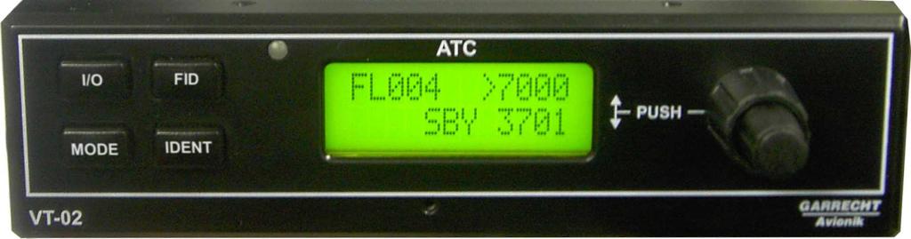
7 2. Switching on and off Press the On/Off key shortly to switch on the unit. After the system start, the screens shown below are displayed. If the system power is interrupted shortly (less than 10 seconds.), the unit restarts in a quick boot mode and continues operation within 1 second. In this case the screenshots shown below will be skipped automatically. Garrecht Start screen showing system name and manufacturer VT-02 SteeringUnit Softw.v 1.20 Mode-S Addr. 12AB34 hex Mode-S Addr. INVALID running in A/C mode FL045 >0021 SBY 0022 Next page: wait for 3 seconds or press any key Information about Steering unit (=CPNL) S/N = Serial number HW = Hardware release SW = Firmware release Entered Mode-S Adress (hex format) Note: If no Mode-S Adress has been entered, confirm the Messages below by pressing any key except ON/OFF This screen will be shown only, if no Mode-S address has been entered. Confirm it by pressing any key except ON/OFF. This screen will be shown only, if no Mode-S address has been entered. Confirm it by pressing any key except ON/OFF. Main screen of the operating system after performing self tests and showing all the screens above. When switched on manually or after power interruption greater than 10 seconds the system is set to the Standby (SBY) mode always. To switch off the system, press the on/off key and hold it for at least 3 seconds. When holding the key, the system counts down from 3 seconds to zero. When the screen is blank, release the key. Revision:
8 3. Normal Operation When in normal operation mode, the following screen is shown by the system: Altitude (FL) Current replycode FL045 >0021 R ALT 0022 Reply- Indicator Current mode Standby- Replycode The current pressure altitude (related to 1013,25 hpa) will be shown as Flightlevel (FL) in the upper left corner of the LCD screen. Replies are indicated by a blinking <R> in the lower left corner of the LCD screen Selecting a Mode The current mode is shown in the centre of the bottom line of the screen. Pressing the mode key circulates through the following modes: Screen Mode Description/function SBY Standby Standby - System is switched on, no replies or squitters will be sent. ON System operating, no alticode will be replied Selected reply code will be replied for Mode- A/C interrogations, altitude information is set to zero, squittering is enabled, Mode-S interrogations will be replied. Switch to this mode only if required by ATC. ALT System operating, alticode will be replied Selected reply code will be replied for Mode- A/C interrogations, altitude information is set to indicated value, squittering is enabled, Mode-S interrogations will be replied. Revision:
9 3.2. Setting up pilot specific data Flight id / aircraft registration / company callsign A Mode-S transponder broadcasts the flight id (FID, company callsign for commercial aircraft or the aircraft registration for smaller private operated aircraft). The flight id may be changed if required. Usually the FID is the callsign of your aircraft unless field 7 of the flight plan contains other data. Always check before each flight if your flight id has been set correctly. Follow these steps to set the flight id / aircraft registration: Set the unit to standby (SBY) mode Press the flight ID key The current flight id will be shown on the screen now. flight-id DABCD Flight-ID / aircraft registration To modify the flight id, press the inner knob of the double shaft rotary encoder. The underlined first digit of the flight id indicates the edit mode. Use the outer knob of the rotary encoder to select the position to be modified. Use the inner knob of the rotary encoder to modify the selected value. Do not enter dashes or blanks even when used in your aircraft registration or company callsign. The data must be entered left aligned. To finish editing the flight id press the inner knob of the rotary encoder. Exit the flight id page by pressing the FID key. Revision:
10 Display illumination and contrast Depending on pilot's preferences, the display and button illumination can be configured and the contrast can be adjusted. How to set up the illumination and adjust LCD contrast: Set unit to standby (SBY) mode Enter the installation set up by simultaneously pressing key 1 (power-on/off) and the push button of the rotary encoder. The LCD now shows password. Rotate the outer knob of the double shaft rotary encoder to select the menu illumination or LCD contrast Press the inner knob of the double shaft rotary encoder to invoke the edit mode. Rotate the inner knob double shaft rotary encoder to select the desired value. Leave the menu by pressing the <Mode> key. Password Use the outer knob of the double shaft rotary encoder to select the desired submenu. Possible values: on LCD backlight and button illumination on, automatic brightness control illumination on lcd contrast 140 off LCD backlight and button illumination always off. 30s Illumination will be switched off automatically 30 sec. after the last user input. Pressing a button or using the rotary encoder switches on the illumation again. Press the inner button of the double shaft rotary encoder and rotate it then to set up the desired values. Sets the basic value for the LCD contrast. Additionally, the system provides an automatic temperature dependent contrast control. Revision:
11 Standard VFR-Code presetting To simplify operation, the VT-02 provides a pre-programmable VFR code, which can be invoked by pressing the inner knob of the rotary encoder longer than 2sec. For modification of the VFR code, please follow the steps shown below: Set unit to standby (SBY) mode Enter the installation set up by simultaneously pressing key 1 (power-on/off) and the push button of the rotary encoder. The LCD now shows password. Rotate the outer knob of the double shaft rotary encoder to select the menu VFR-Preset contrast Press the inner knob of the double shaft rotary encoder to invoke the edit mode. Rotate the inner knob of the double shaft rotary encoder to modify the selected value. Use the outer knob of the double shaft rotary encoder to select the desired digit position. Leave the menu by pressing the <Mode> key. VFR-Preset 7000 Standard VFR-Codes (as of 1. January 2008): Europe: 7000 (default seeting) USA: 1200 To obtain VFR codes for other regions, please contact your national aviation authority Revision:
12 multiple profiles (optional function) The VT-02 offers a multiple profile feature optionally. Profiles allow to store five different sets of aircraft specific data, such as Mode-S Adress, Flight ID and other settings related to the aircraft. When moving the transponder to another aircraft (especially in the balloons), you can easily select the appropriate configuration for this aircraft, if entered before. Refer to the installation manual to learn more about setting up the profiles. In the standard configuration, only one profile is provided. This function needs to be purchased by the manufacturer or it's representative. How to select an entered profile: Set unit to standby (SBY) mode Enter the profile setup by simultaneously pressing key 1 (power-on/off) and the push button of the rotary encoder. The LCD now shows password. Press the inner knob of the double shaft rotary encoder to invoke the edit mode. Enter the following password: using the rotary encoder. Rotate the inner knob of the double shaft rotary encoder to modify the selected value. Use the outer knob of the double shaft rotary encoder to select the desired position in the string. After entering the password above, the system LCD shows: PR2:D0815 hex 3CFA4B The upper line shows the number of the selected profile and the flight ID / callsign. The lower line shows the Mode-S adress for this profile entered in the post installation setup. Rotating the inner or outer knob of the encoder selects the desired profile. Confirm your selection by pressing the inner knob of the rotary encoder or just wait for 10 sec. Modifications are not possible in this menu, except the Flight ID. For entering the data shown above, please refer to the installation manual. If you have not purchased for the multiple profiles feature, the system offers one profile only. Selecting another profile than profile-1 is not possible. Revision:
13 3.3. Ident function If required by ATC, press the IDENT key. Ident-Flag FL045 i0021 R ALT 0022 Pressing the ident key invokes the ident mode for 18 sec. Ident activity is shown by a i in the middle of the upper line on the LCD screen, which starts blinking after 4 sec. as long as ident is acitve. Press the ident key only if requested by ATC! Revision:

14 3.4. Selecting the reply code Use the double shaft rotary encoder to select or modify the standby reply code of your transponder. inner Knob outer Knob Select the position to be modified by rotating the outer knob. The selected position will be indicated by an underlined cursor Use the inner knob to set the required value. If all positions of the standby reply codes contain the required values, press the inner knob of the rotary encoder to activate the modified code. It will replace the code shown in the position of the active reply code. Active reply code FL045 >0021 R ALT 0022 Standbyreply code Sample: Mode-A reply code needs to be changed. Use the outer knob of the double shaft encoder to select the position of the code to be modified. A blinking cursor is indicating the selected position. Use the inner knob to modify the value at the selected position. When all changes are done, press the inner button to activate the modified standby code. Revision:
15 3.5. VFR Function To simplify operation, the VT-02 provides a pre-programmable VFR code, which can be invoked by pressing the inner knob of the rotary encoder longer than 2sec. The previous active reply code will then be moved to the bottom line (inactive area) and overwrites the existing value there. If the pre-programmed reply code is identical with the reply code in the bottom line, active and standby reply code will just be swapped. Revision:
16 4. Warnings / Error messages System failures will be detected by the internal self test function that is performed continuously. Failures are detected malfunctions, which can not be eliminated by the user. Warnings are conditions, which may be followed by a failure. Warnings can be eliminated by the user under several conditions. Failures and warnings will be indicated by a visual and audible signal. If restarting the unit continues to generate the same error, please contact your avionic shop or your dealer. In case of malfunction, error codes will be shown at the usual position, but more detailed. Please write down the error code shown on the screen to improve our service Failure messages Failure code!cntl! >FAIL W SBY FAIL Failure flag In case of failure, the system shows a W on the LCD screen. Additonally, a frequently repeated audible signal occurs. Both can be terminated by pressing the on/off key shortly. In case of detecting a severe failure, the system will be switched into Standby (SBY) mode. All system operating will be terminated to prevent damages to system components. In this case, the system screen will show FAIL instead of active and standby reply code. General: In case of failure or warning, an abbreviated failure message will be displayed alternating with the displayed alticode. Pressing the mode key to select mode on or alt, the system continues operating until a new failure is detected. If a system failure has been detected by the system, always inform ATC, if you are flying in a transponder mandatory zone or other airspace, where a transponder is required. Never try to find the reason for a system failure or warning during the flight!!! Revision:
17 4.2. Warnings The system warns the pilot if malfunctions have been detected that could lead to a severe failure. It is up to the pilot to eliminate these conditions. Warnings are indicated in case of undervoltage or operating the system out of the certified altitude range. Warning code!altc! >0021 RW ALT 0022 Warning indicator In case of warning, the system shows a W on the LCD screen. Additonally, a frequently repeated audible signal occurs. Both can be terminated by pressing the on/off key shortly. The system continues operation, but it may be limited. If an error of the alticoder unit is detected or the system is operated out of the certified altitide range, the replied alticode will be set to zero (same as mode ON) General: In case of failure or warning, an abbreviated failure message will be displayed alternating with the displayed alticode. Pressing the mode key to select mode on or alt, the system continues operating until a new failure is detected. If a system failure has been detected by the system, always inform ATC, if you are flying in a transponder mandatory zone or other SUA, where a transponder is required. Never try to find the reason for a system failure or warning during the flight!!! 4.3. Error codes The following table shows the meaning of displayed failure and warning codes. Failures marked with an * may be caused in the system installation. Other failure or warning codes are caused by internal malfunctions. In this case the system needs to be repaired by an authorised repair shop. Code Description Possible reason!squit! Malfunction in transmitter Squitter Error module!vsup! Supply voltage low Battery empty!ant! * Antenna failure Bad antenna or antenna cable!prss! Pressure sensor failure Internal malfunction!comm! * CAN bus communication error Short in CAN-bus or internal malfunction!txpl! Transmitter PLL failure Internal malfunction!fpga! FPGA checksum failure Internal malfunction Revision:

18 5. Info menu For maintenance and diagnostics, the firmware version can be read following the steps shown below: Press the on/off key and hold it. Then Press the ident key within 3 sec. The LCD screen shows Info. Press the inner knob of the rotary encoder to start displaying the following information. Info menu Garrecht VT-02 SteeringUnit Softw.v 1.20 Mode-S Addr. 12AB34 hex Central Unit Softw.v.1.60 Central Unit FPGA v.011 Key:C1943AF1 Revision:
Garrecht Avionik GmbH VT-02 Transponder User Manual Document E. Secondary Surveillance Radar Transponder Mode-S
 VT-2000 Secondary Surveillance Radar Transponder Mode-S User manual Add this manual to the flight instruction manual of your aircraft 2007-2012 - Garrecht Avionik GmbH, 55411 Bingen/Germany Revision: 1.2a
TRX Operation Manual Installation Manual. ADS-B Traffic Receiver Garrecht Avionik GmbH, Bingen/Germany
 TRX-1090 ADS-B Traffic Receiver Operation Manual Installation Manual 2011 - Garrecht Avionik GmbH, 55411 Bingen/Germany Revision: 1.0f 1 31 MAR 2011 Record of Revisions Always keep this page in front of
AFMS, Garmin G5 AML STC Rev. 1 FAA APPROVED Page 2 of 7
 LOG OF REVISIONS Date of Rev Page Description FAA Approval Approval 1 All Original Issue See Cover See Cover FAA APPROVED Page 2 of 7 TABLE OF CONTENTS SECTION 1. GENERAL... 4 SECTION 2. LIMITATIONS...
TRX User Manual Installation Manual. ADS-B Trafficmonitor Garrecht Avionik GmbH, Bingen/Germany
 TRX-2000 ADS-B Trafficmonitor User Manual Installation Manual 2011 - Garrecht Avionik GmbH, 55411 Bingen/Germany Revision: 1.0b 1 19 DEC 2011 Record of Revisions Always keep this page in front of this
The GF-2 is able to measure G-forces even if the instrument is not mounted exactly on the vertical axis of the aircraft.
 GF-2 +-10g Tilt Compensated dual range aviation G-force meter Operating Manual English 1.00 Introduction The GF-2 is a 3 1/8 G-force meter capable of measuring G-forces exerted in an aircraft up to +-10g.
AFMS, Garmin G5 AML STC Rev. 3 Page 2 of 10
 LOG OF REVISIONS Rev Page Description Date of Approval FAA Approval 1 All Original Issue 7/22/2016 Robert Murray ODA STC Unit Administrator 2 All Added information regarding G5 DG/HSI 4/28/2017 Robert
FlarmView and FlarmView57
 FlarmView and FlarmView57 Flarm collision avoidance display Version 1.01 LXNAV d.o.o. Kidričeva 24a, 3000 Celje, Slovenia tel +386 592 33 400 fax +386 599 33 522 info@lxnav.com www.lxnav.com 1 Important
GF-1. Introduction. 1 Features. +-10G Tilt Compensated dual range aviation G-force meter. Operating Manual English 1.00
 GF-1 +-10G Tilt Compensated dual range aviation G-force meter Operating Manual English 1.00 Introduction The GF-1 is a 2.25 G-force meter capable of measuring G-forces exerted in an aircraft up to +-10G.
Troubleshooting. Resetting the System. Problems Following Initial System Installation. First Steps Checklist CHAPTER
 CHAPTER 6 This chapter helps you identify and solve problems that might occur while you are using the Cisco CDE110. If you are unable to resolve your server problems on your own, contact Cisco Technical
用户手册. KT-LCD6 ebike Special Meter
 用户手册 User Manual KT-LCD6 ebike Special Meter WWW.SZKTDZ.COM Contents Preface... 4 Outlook and Size... 4 Meter Dimension 4 Button Box Dimension.. 4 Main Material and Color.... 5 Wiring Schematic.. 5 Installation
Swapping GTX 1 & GTX 2 (GTX 33ES) on Citation Mustang
 on Citation Mustang") Swapping GTX 1 & GTX 2 (GTX 33ES) on Citation Mustang Garmin G1000 Software Version 28 Note: Before starting the software or configuration loading process, certain items may be required to be recorded
Swapping GTX 1 & GTX 2 (GTX 33ES) on Citation Mustang Garmin G1000 Software Version 28 Note: Before starting the software or configuration loading process, certain items may be required to be recorded
DJI MATRICE 600 PRO Release Notes
 Date : 2017.10.24 Aircraft Firmware : V 1.0.1.65 DJI GO App : ios V 3.1.18, Android V 3.1.11 DJI Assistant 2 : V 1.1.6 Aircraft Firmware: Increased flight safety. Fixed issue of output error when F channel
XL-RAID-213SA User Manual
 XL-RAID-213SA User Manual Introduction English Thank you for purchasing our products. This manual will introduce the XL-RAID-213SA Series. Before using your XL-RAID-213SA, please read this manual thoroughly.
GTX 335 Setup Wizard Guide
 GTX 335 Setup Wizard Guide 190-01499-40 February, 2018 Revision E 2018 Garmin International, Inc. or its subsidiaries All Rights Reserved Except as expressly provided herein, no part of this manual may
ilevil 3 AW Wireless Integrated Avionics Module AD-AHRS, GPS, ADS-B 978 / 1090 MHz Receiver, Data recorder Instruction Manual
 ilevil 3 AW Wireless Integrated Avionics Module AD-AHRS, GPS, ADS-B 978 / 1090 MHz Receiver, Data recorder Instruction Manual ilevil 3 AW SD CARD PORT GPS ANTENNA ADS-B ANTENNA MINI USB PORT CHARGING LED
Installation and Operation Back-UPS BR1000G-IN / BR1500G-IN
 Installation and Operation Back-UPS BR1000G-IN / BR1500G-IN Important Safety Information Read the instructions carefully to become familiar with the equipment before trying to install, operate, service
广州谐同电子科技有限公司 Guangzhou Electrony Corporation 用户手册. User Manual. S-LCD3 ebike Special Meter
 广州谐同电子科技有限公司 Guangzhou Electrony Corporation 用户手册 User Manual S-LCD3 ebike Special Meter WWW.ELECTRONY.CN Contents Preface... 4 Outlook and Size... 4 MeterDimension 4 Button Box Dimension.. 4 Main Material
 ! o o o o o o o o o (Per the February 9, 2015 rule change to 14 CFR 91.225 (b)(1)(ii)) (A letter of authorization from the aircraft manufacturer is needed for installation in LSA aircraft) ± ! ADF
Review of. Boeing 737 COM, ATC, BRT & EFIS Modules. Manufactured by CPflight
 Review of Boeing 737 COM, ATC, BRT & EFIS Modules Manufactured by CPflight The ultimate upgrade to most flight simulation enthusiast s virtual experience is to build a complete home cockpit to gain the
Owner s Manual. Network Player
 G Network Player Owner s Manual This product is designed for use at home to enjoy listening to audio. Before using this product, read the safety instructions described in the supplied Quick Start Guide.
Game Mode...29 Settings Mode...30 Using the AVI Converter Software...36 Troubleshooting...40
 Contents Important Notice...3 Safety Instructions...4 Product feature...5 Front view...7 Minimum System Requirements...8 Connect USB...8 Get Started...9 Power ON / Power OFF...9 Set Key Lock...9 Music
Innovative concepts in SDP Facing new challenges in aircraft position tracking and prediction
 Surveillance Services Info Days Brussels, 6-7 December 2017 Innovative concepts in SDP Facing new challenges in aircraft position tracking and prediction Johannes De Haan SDDS Service Manager TLP: GREEN
Owner s Manual Digital Recording Systems GDS-R04A ASP AG
 Owner s Manual Digital Recording Systems GDS-R04A External Storage GDS-R04A.15.1.02.08.2011 ASP AG Content: 1. Introduction 1 2. Key Features of the GDS-R04A 2 3. Package Contents 2 4. Installation 3
FlarmView and FlarmView57
 FlarmView and FlarmView57 Flarm collision avoidance display Version 2.36 LXNAV d.o.o. Kidričeva 24a, 3000 Celje, Slovenia tel +386 592 33 400 fax +386 599 33 522 info@lxnav.com www.lxnav.com 1 Important
SD ENCODER AND MODULATOR YPbPr & CVBS TO DVB-T DIGITAL RF SD4250 USER MANUAL
 SD ENCODER AND MODULATOR YPbPr & CVBS TO DVB-T DIGITAL RF SD4250 USER MANUAL All-in-one encoder and modulator for dual SD source. Allows 4 sets of Audio/Video source to be extended throughout a traditional
Table of Contents. 3.1 Front/Rear Panel and User Interface Front Panel Rear Panel User Interface...
 General Warranty OWON warrants that the product will be free from defects in materials and workmanship for a period of 2 years (1 year for accessories) from the date of purchase of the product by the original
DJI MATRICE 600 Release Notes
 Date : 2018.04.17 Aircraft Firmware : V 1.0.1.66 DJI GO App : ios V 3.1.31, Android V 3.1.30 DJI Assistant 2 : V 1.1.7 Aircraft Firmware: Improved altitude measuring precision by lowering barometer drift
D-0005 BOM (Broadcasting Outer Module) Pilot s Guide LEVIL AVIATION 1704 KENNEDY POINT, SUITE 1124 OVIEDO, FL 32765
 Pilot s Guide LEVIL AVIATION 1704 KENNEDY POINT, SUITE 1124 OVIEDO, FL 32765") 2017 D-0005 BOM (Broadcasting Outer Module) Pilot s Guide LEVIL AVIATION 1704 KENNEDY POINT, SUITE 1124 OVIEDO, FL 32765 Effective Date 11/7/17 Page 1 of 12 This manual is the property of Levil Aviation.
2017 D-0005 BOM (Broadcasting Outer Module) Pilot s Guide LEVIL AVIATION 1704 KENNEDY POINT, SUITE 1124 OVIEDO, FL 32765 Effective Date 11/7/17 Page 1 of 12 This manual is the property of Levil Aviation.
GRUNDFOS INSTRUCTIONS. Control MPC. Installation and operating instructions
 GRUNDFOS INSTRUCTIONS Control MPC Installation and operating instructions English (GB) English (GB) Installation and operating instructions Original installation and operating instructions CONTENTS Page
SAS JBOD Installation Reference Guide Revision 1.0
 SAS JBOD 16-bay Rackmount Enclosure Installation Reference Guide Revision 1.0 P/N: PW0020000000281 Copyright No part of this publication may be reproduced, stored in a retrieval system, or transmitted
TABLE OF CONTENTS TABLE OF CONTENTS... 1 MANUAL REVISION HISTORY... 2 IMPORTANT SAFETY NOTICE...
 TABLE OF CONTENTS TABLE OF CONTENTS... 1 MANUAL REVISION HISTORY... 2 IMPORTANT SAFETY NOTICE... 3 1.0 General Information... 5 1.1 System Components... 5 1.2 Specifications... 5 1.2.1 Torque Ranges...
KA11AIR Receiver. PLL FM Stereo/Aircraft Synthesized Receiver. Operation Manual
 KA11AIR Receiver PLL FM Stereo/Aircraft Synthesized Receiver Operation Manual WARRANTY INFORMATION The KA11AIR receiver is warranted for one year from the date of purchase by Gleim Publications Inc. to
: EUROCONTROL Specification. Surveillance Data Exchange ASTERIX Part 12 Category 21 Appendix A Reserved Expansion Field
 EUROCONTROL Specification for Surveillance Data Exchange ASTERIX Part 12 Category 21 Appendix A Reserved Expansion Field DOCUMENT IDENTIFIER : Edition Number : 1.4 Edition Date : 08/03/2018 Status : Released
SI3300. user and installation manual. 4-20mA/DC-Digital Display
 SI3300 4-20mA/DC-Digital Display The SI3300 is a member of the SI3000 Readout Family. All members of the family are marked SI3000 on the front panel. This manual is specifically for the SI3300 Model with
Operating Instructions NEMCO Taskmaster 8-Channel & 16-Channel Programmable Timer
 Operating Instructions NEMCO Taskmaster 8-Channel 2550-8 & 16-Channel 2550-16 Programmable Timer NEMCO Food Equipment 301 Meuse Argonne Street Hicksville, OH 43526 419-542-7751 Designed for Today s Fast-Paced
用户手册. User Manual. S-LCD8 ebike Special Meter
 用户手册 User Manual S-LCD8 ebike Special Meter WWW.BMSBATTERY.COM Contents Preface... 4 Outlook and Size... 4 Meter Dimension 4 Button Box Dimension..5 Main Material and Color.... 5 Wiring Schematic.. 5 Installation
Helios user`s manual version 1.8
 Helios user`s manual version 1.8 Page 1 of 24 LX Helios Speed to fly variometer, final glide calculator and simple navigation system with internal backup battery. User s manual (version 1.8) Refers to
VSI200E Vertical Speed Indicator with Altitude Encoder
 VSI200E Vertical Speed Indicator with Altitude Encoder THIS IS A TRANSPORT CANADA APPROVED MANUAL The following checklist outlines the required articles for the VSI200E Vertical Speed Indicator. Documentation
BASIC IVAP FUNCTIONS FOR FS
 1. Introduction BASIC IVAP FUNCTIONS FOR FS In this document, you will be instructed how to use IvAp (IVAOs pilots tool) properly. This is just a short overview of the basics required for the PP exam.
Section 1: Aircraft Information
 Aircraft Spruce Panel Builder Website User Help To insure this site works correctly, make sure your computer supports Java & allows pop-ups. This site is can be broken down into five sections. Aircraft
MANUAL PELITT MINI 1
 MANUAL PELITT MINI 1 TABLE OF CONTENTS 1. Warnings 3 2. Getting Started 3 3. Your Phone 4 4. File Manager 4 5. Phone book 4 6. Fun&Games 4 7. Call center 4 8. Messaging 4 9. Multimedia 5 10. Organizer
LC-110/H. Reference Manual
 LC-110/H Reference Manual 1. Introduction...1 1.1 Customer Service...1 1.2 Standard Equipment...2 1.3 Safety information...2 2. Calibrator Interface and Operation...5 2.1 Milliamp Source...6 2.2 Milliamp
T E C H N O L O G I E S. User Guide. 1:1 HDD Duplicator PRO (HDUSI325)
") T E C H N O L O G I E S Duplicator Panel Power Switch Source Drive Bay Target Drive Bay User Guide 1:1 HDD Duplicator PRO (HDUSI325) www.addonics.com v3.1.11 Technical Support If you need any assistance
T E C H N O L O G I E S Duplicator Panel Power Switch Source Drive Bay Target Drive Bay User Guide 1:1 HDD Duplicator PRO (HDUSI325) www.addonics.com v3.1.11 Technical Support If you need any assistance
IGB Series. Operation Manual. Platform Scale. Kg/Lb Specification IMPORTANT
 Platform Scale IGX/ Kg/Lb Specification Operation Manual IMPORTANT Do not carry out installation, operation, service, or maintenance until thoroughly understanding the contents of this manual. Keep this
Contents. Product name and model... 1 Specifications... 1 Appearance and Size... 1 Function Summary and Button Definition... 2 Function Summary...
 Contents Product name and model... 1 Specifications... 1 Appearance and Size... 1 Function Summary and Button Definition... 2 Function Summary... 2 Button Definition... 2 Assembly... 2 Function Area Distribution...
AT01 AIRPLANE FLIGHT MANUAL
 1.0 General The airplane is equipped with a Bendix / King KMD 150 Multifunction Display / GPS Navigator herein referred as the Navigator. The KMD 150 is capable of providing VFR (IFR) enroute and terminal
TSS-7/TSS-10 7" and 10.1" Room Scheduling Touch Screens
 TSS-7/TSS-10 7" and 10.1" Room Scheduling Touch Screens Supplemental Guide Crestron Electronics, Inc. Crestron product development software is licensed to Crestron dealers and Crestron Service Providers
Replacing PFD 2 (GDU 1040A) on Citation CJ
 on Citation CJ") Replacing PFD 2 (GDU 1040A) on Citation CJ Garmin G1000 Software Version -02 Caution: Caution: Caution: Caution: Before starting the software or configuration loading process, certain items may be required
Replacing PFD 2 (GDU 1040A) on Citation CJ Garmin G1000 Software Version -02 Caution: Caution: Caution: Caution: Before starting the software or configuration loading process, certain items may be required
用户手册. User Manual. KT-LCD5 ebike Special Meter
 用户手册 User Manual KT-LCD5 ebike Special Meter WWW.SZKTDZ.COM Contents Preface... 3 Outlook and Size.. 3 Meter Dimension 3 Main Material and Color....... 3 Wiring Schematic. 3 Installation Instruction..
Firmware Update 3.0 MSA G1 SCBA
 Firmware Update 3.0 MSA G1 SCBA The MSA G1 SCBA was developed with the promise to provide continuous advancements in technology. Fulfilling that promise, MSA is pleased to announce the release of the G1
user and installation manual
 SI3500 SI3500 ORBIT Digital Display The SI3500 is a member of the SI3000 Readout Family. All members of the family are marked SI3000 on the front panel. This manual is specifically for the SI3500 Model
DEUTSCH ENGLISH NEDERLANDS FRANÇAIS NORSK ITALANIO ČEŠTINA Hersteller DAB650SI
 DEUTSCH NEDERLANDS NORSK ČEŠTINA ENGLISH FRANÇAIS ITALANIO Hersteller Wörlein GmbH Tel.: +49 9103/71670 Gewerbestrasse 12 Fax.: +49 9103/716712 D 90556 Cadolzburg Email. info@woerlein.com GERMANY Web:
List of Contents 1. INTRODUCTION DEFINITIONS AND ABBREVIATIONS REFERENCES TECHNICAL DATA GENERAL MODBUS RTU...
 MAGX2 RTU User Guide -0- V1.5 23-01-2018 List of Contents 1. INTRODUCTION... 2 1.1 DEFINITIONS AND ABBREVIATIONS... 2 1.2 REFERENCES... 2 2. TECHNICAL DATA... 3 2.1 GENERAL MODBUS RTU... 4 3. COMMISSIONING...
ARA FTS Flow Calibrator. Operation Manual August 1, 2016
 ARA FTS Flow Calibrator Operation Manual August 1, 2016 TABLE OF CONTENTS SECTION PAGE 1. INTRODUCTION 1 2. GETTING STARTED 1 2.1. Navigation 1 2.2. Charge Battery 1 2.3. Set Date and Time 2 2.4. Plug-In
DJI Ace One product release notes
 Date : 26 July 2012 Ace One firmware version : 4.02 Ace Assistant software version : 2.4 Low Voltage Warning Semi Auto Takeoff & Landing (Optional) Ground Station chargeable functions: View (optional)
TABLE OF CONTENTS TABLE OF CONTENTS... 1 IMPORTANT SAFETY NOTICE...
 TABLE OF CONTENTS TABLE OF CONTENTS... 1 IMPORTANT SAFETY NOTICE... 2 1.0 General Information... 3 1.1 System Components... 3 1.2 Specifications... 3 1.2.1 Torque Ranges... 3 1.2.2 Electrical Specifications...
Kanguru USB Duplicator Quick Start Guide
 Kanguru USB Duplicator Quick Start Guide Models: U2D This is a Quick Start Guide only. For detailed information about your Kanguru USB Duplicator, please refer to the User Guide. A digital copy of the
AS-i Safety Relay Output Module with Diagnostic Slave
 AS-i Safety Relay Output Module with Diagnostic Slave User Manual Revision date: 2013-01-30...supports the requirements for AS-i Safety up to SIL3 Subject to modifications without notice. Generally, this
Intelligent Operator Panel (IOP)
") Safety notes 1 Overview 2 SINAMICS SINAMICS G110D, SINAMICS G110M, SINAMICS G120, SINAMICS G120C, SINAMICS G120D Operating Instructions Installation 3 Wizards 4 Control 5 Menu 6 Options 7 Technical data
Safety notes 1 Overview 2 SINAMICS SINAMICS G110D, SINAMICS G110M, SINAMICS G120, SINAMICS G120C, SINAMICS G120D Operating Instructions Installation 3 Wizards 4 Control 5 Menu 6 Options 7 Technical data
Installation Manual RB-RWS20-E. Lite-Vision plus Remote Controller. Model name: English
 Model name: RB-RWS20-E Read this manual before using the RB-RWS20-E remote controller. Refer to the supplied with the indoor unit for any installation instructions other than operations of the remote controller.
Keypad LCD (software version 3.10) CA-10 plus
 CA-10 plus") PROGRAMMING AND INSTALLATION MANUAL Keypad LCD (software version 3.10) CA-10 plus GDAŃSK ca10plci_e 09/03 WARNING Due to safety reasons, alarm system should be installed by qualified personnel only. Because
PROGRAMMING AND INSTALLATION MANUAL Keypad LCD (software version 3.10) CA-10 plus GDAŃSK ca10plci_e 09/03 WARNING Due to safety reasons, alarm system should be installed by qualified personnel only. Because
SlimLine. Compliant to DO-160D. Document # Rev G. www. rosenaviation.com. www. rosenaviation.com
 6.5 Model DISPLAY SlimLine Number 6500 www. rosenaviation.com CORPORATE OFFICE 1020 Owen Loop South Eugene, OR 97402 1-888-668-4955 Fax (541) 342-4912 6500 www. rosenaviation.com Document # 9002751 Rev
Operating instructions. Standstill monitor A / / 2011
 Operating instructions Standstill monitor A300 UK 1 2 3 4 5 6 7 8 7390337 / 01 02 / 2011 1 2 3 4 5 6 7 8 switchpoint min max pulse/min power Made in Germany ifm electronic gmbh D 45127 Essen func. I II
1:5 Combo msata HDD Duplicator (MSHDUS5HS)
") 1:5 Combo msata HDD Duplicator (MSHDUS5HS) www.addonics.com Technical Support If you need any assistance to get your unit functioning properly, please have your product information ready and contact Addonics
1:5 Combo msata HDD Duplicator (MSHDUS5HS) www.addonics.com Technical Support If you need any assistance to get your unit functioning properly, please have your product information ready and contact Addonics
Handbook ASI-PRG-ADR. AS-Interface Addressing Device. Festo AG & Co de 0004a
 Handbook ASI-PRG-ADR AS-Interface Addressing Device Festo AG & Co. 360 039 de 0004a AS-Interface is a registered Trademark of the AS-International Association We recognise a duty to make a contribution
AG-NAV GUÍA LITE Differential GPS Guidance System. OPERATOR S HANDBOOK Version Sept. 2017
 AG-NAV GUÍA LITE Differential GPS Guidance System OPERATOR S HANDBOOK Version 1.1.5 Sept. 2017 INFORMATION AG-NAV INC. 30 Churchill Drive Barrie, Ontario L4N 8Z5 CANADA TOLL FREE: (800) 99-AGNAV TELEPHONE:
IPT Auto Configuration IPedge/VIPedge Feature Description 3/6/13
 IPT Auto Configuration IPedge/VIPedge Feature Description 3/6/13 OVERVIEW The IPT Auto Config feature automatically performs the IPT station configuration functions that would otherwise require programming
AC OPERATION BATTERY OPERATION RADIO OPERATION Note : FM STEREO INDICATOR ANTENNAS BASS BOOST AUXILIARY (AUX) MODE
 MODE") 1. FUNCTION SWITCH AUX/CD/TAPE (OFF)/RADIO 2. BAND SWITCH 3. FM ANTENNA 4. CD DOOR 5. TUNING KNOB 6. BASS BOOST BUTTON 7. CD SKIP/SEARCH FORWARD BUTTON 8. CD SKIP/SEARCH BACKWARD BUTTON 9. CD PROGRAM BUTTON
1. FUNCTION SWITCH AUX/CD/TAPE (OFF)/RADIO 2. BAND SWITCH 3. FM ANTENNA 4. CD DOOR 5. TUNING KNOB 6. BASS BOOST BUTTON 7. CD SKIP/SEARCH FORWARD BUTTON 8. CD SKIP/SEARCH BACKWARD BUTTON 9. CD PROGRAM BUTTON
AS-i Safety Relay Output Module with Diagnostic Slave
 AS-i Safety Relay Output Module with Diagnostic Slave User Manual...supports the requirements for AS-i Safety up to SIL3 Revision date: 2016-03-9 Subject to modifications without notice. Generally, this
Supplementary device manual EtherCAT interface in the AS-i controllere A AC1391 AC1392
 Supplementary device manual EtherCAT interface in the AS-i controllere A AC1391 AC139 firmware version RTS.x target from 15 for CoDeSys from version.3 English 739071_00_UK 01-0- Contents Revision: 16 December
GOLD SERIES DVD/CD Duplicator Manual
 GOLD SERIES DVD/CD Duplicator Manual User s Manual Version 3.0 0 TABLE OF CONTENTS Introduction 2 Setup 11 LCD Front Panel Overview 2 o Auto Start Time 11 Menu Overview 3-5 o Display Mode 12 Functions
Altair RU. Owner s Manual. Document name: AtrRU-EN Document version: 0.3 Release date: 25/03/2009
 Altair RU Owner s Manual Document name: AtrRU-EN Document version: 0.3 Release date: 25/03/2009 triadis engineering GmbH Eichholzstrasse 7 Postfach CH-3254 Messen Phone: +41 (0)31 768 15 15 Fax: +41 (0)31
model: 660 Quick Start Manual
 model: 660 Quick Start Manual Copyright 2016-2018 Garmin Ltd. or its subsidiaries. All rights reserved. This manual reflects the operation of System Software version 3.3 or later. Some differences in
EPM Programmer EEPM1RA
 EP01E - en EN Operating Instructions COPY epm001 EPM Programmer EEPM1RA 2004 Lenze gmbh & C0 KG No part of this documentation may be copied or made available to third parties without the explicit written
IS35 Color Display. User Manual ENGLISH. simrad-yachting.com
 IS35 Color Display User Manual ENGLISH simrad-yachting.com Preface Navico is continuously improving this product, therefore we retain the right to make changes to the product at any time which may not
LX Helios. Speed to fly variometer, final glide calculator and simple navigation system with internal backup battery. User s manual (version 1.
 LX Helios Speed to fly variometer, final glide calculator and simple navigation system with internal backup battery. User s manual (version 1.4) Refers to LX Helios FW version 1.4 Tkalska 10 SI 3000 Celje
The following documents are included with your Sony VAIO computer.
 Documentation The following documents are included with your Sony VAIO computer. Printed Documentation Quick Start Guide Describes the process from unpacking to starting up your VAIO. Troubleshooting and
CM-220 True RMS AC CLAMP METER INSTRUCTION MANUAL
 CM-220 True RMS AC CLAMP METER INSTRUCTION MANUAL Safety International Safety Symbols This symbol, adjacent to another symbol or terminal, indicates the user must refer to the manual for further information.
Troubleshooting. User Guide
 Troubleshooting User Guide Copyright 2006 Hewlett-Packard Development Company, L.P. Microsoft and Windows are U.S. registered trademarks of Microsoft Corporation. The information contained herein is subject
DV-4900 DV-4070 DVF-R9030 DVF-R7030
 DV-4900 DV-4070 DVF-R9030 DVF-R7030 Multiple DVD VCD CD B60-4715-00 00 CS (T,K,M,X) AP 0004 B60-4714-00 00 SC (T,K,M,X) AP 0004 2 Contents Chapter 1: Controls and indicators... 5 Front Panel... 6 Display...
Aeronautical Navigator USER MANUAL. Your Journey, Our Technology
 Aeronautical Navigator USER MANUAL Your Journey, Our Technology INDEX Navigatore Aeronautico AvMap EKPV 1. LEARN BEFORE USE 4 I. Safe temperature range 4 II. Battery and power source recommendations 4
A698HKBK9-E-I RFID Data Management Pro for Mobile Computers. Installation Guide. April 2017 Version 2.40
 A698HKBK9-E-I-0240 RFID Data Management Pro for Mobile Computers Installation Guide April 2017 Version 2.40 Preface This document explains the installation methods for the RFID Data Management Pro for
PME 700 Demolition Stability Monitor
 PME 700 Demolition Stability Monitor Operators Manual This guide describes operation of the PROLEC PME LIFTING AND MACHINE ENVELOPE SAFETY SYSTEM FOR CONSTRUCTION PLANT Model covered : PART No. MODEL
WRTU Client User Manual. Date: 29 May, 2014 Document Revision: 1.05
 WRTU Client User Manual Date: 29 May, 2014 Document Revision: 1.05 2014 by BiPOM Electronics, Inc. All rights reserved. WRTU Client User Manual. No part of this work may be reproduced in any manner without
3D CONTROLLER. User Manual. pdf version of the manual available for download: 11/2017
 3D CONTROLLER 11/2017 User Manual pdf version of the manual available for download: www.slidekamera.com On the margins you will find information, which complement the contents of the manual. They are not
NIDEC-SHIMPO INSTRUMENTS
 TTR Torque Tool Tester Operation Manual NIDEC-SHIMPO INSTRUMENTS 1) Overloading the transducer does not only damage the transducer but may break the transducer head and could result in injury! 2) Torque
Modbus Map: System Control Panel (SCP) Device
 Device") Modbus Map: System Control Panel (SCP) Device 503-0251-01-01 Revision A.1 UNINTENDED OPERATION WARNING The use of this product with Modbus communications requires expertise in the design, operation, and
Modbus Map: System Control Panel (SCP) Device 503-0251-01-01 Revision A.1 UNINTENDED OPERATION WARNING The use of this product with Modbus communications requires expertise in the design, operation, and
VBT-75 S2 VACUUM BOTTLE TESTER
 VBT-75 S2 VACUUM BOTTLE TESTER USER S MANUAL Vanguard Instruments Company, Inc. 1520 S. Hellman Ave. Ontario, California 91761, USA TEL: (909) 923-9390 FAX: (909) 923-9391 July 7, 2017 Revision 1 SAFETY
DIGITAL PUMP CONTROLLER. Model Version October 24, 2011
 DIGITAL PUMP CONTROLLER Model 9954-1 Version October 24, 2011 9954-1 Controller Interconnection Diagram PROGRAMMABLE VOLT-FREE CONTACT (10A 240vAC) (FACTORY FITTED OPTION) FOR REMOTE SIGNALLING CONTROL
 INTRODUCTION This controller is suitable for controlling up to twenty four (24) DMX-512 units of any type with maximum 32 channels respectively (scanner, moving head, strobe, etc). The controller s software
Microair Avionics Pty Ltd Airport Drive Bundaberg Queensland 4670 Australia Tel: Fax:
 Microair Avionics Pty Ltd Airport Drive Bundaberg Queensland 4670 Australia Tel: +61 7 41 553048 Fax: +61 7 41 553049 e-mail: support@microair.com.au About This Document This manual describes the various
RC T3000. Vario and navigation system. Manual version: 1.0. RC Electronic
 RC T3000 Vario and navigation system Manual version: 1.0 RC Electronic support@rc-electronics.org, http://www.rc-electronics.org Contents Introduction... 3 Power supply... 3 Controls... 3 USB Connector...
GAT Handheld Coder Pro+ User Manual
 GAT Handheld Coder Pro+ User Manual Rev 1.2 READ INSTRUCTION CAREFULLY BEFORE USE IF YOU HAVE ANY QUESTIONS ABOUT THE USE OF THIS DEVICE, CONTACT YOUR BIMMER RETROFIT REPRESENTATIVE BEFORE USE HANDHELD
DO NOT LEAVE THIS GUIDE WITH THE PATIENT
 Invacare Polaris EX CPAP with SoftX Assembly, Installation and Operating Instructions Model Number: ISP3000 DO NOT LEAVE THIS GUIDE WITH THE PATIENT NOTE: Check all parts for shipping damage. In case of
GPS Vehicle and personal location tracker
 Version Number Modified by Change Content Type Date V1.0 Amy create 2014.06.23 GPS Vehicle and personal location tracker User Manual GPS Vehicle and personal location tracker User Manual 1 Contents 1.
IN5132/IN5142/IN5134/IN5134a IN5144/IN5144a/IN5135/IN5145 User's Manual (detailed) Instant Stack Guide
 Instant Stack Guide") Projector IN5132/IN5142/IN5134/IN5134a IN5144/IN5144a/IN5135/IN5145 User's Manual (detailed) Instant Stack Guide Thank you for purchasing this product. Features This projector can be used in conjunction
Projector IN5132/IN5142/IN5134/IN5134a IN5144/IN5144a/IN5135/IN5145 User's Manual (detailed) Instant Stack Guide Thank you for purchasing this product. Features This projector can be used in conjunction
W Warning To avoid electrical shock, remove test leads and any input signals from the Model 707 Loop Calibrator before opening the case.
 Model 707 Loop Calibrator W Warning To avoid electrical shock, remove test leads and any input signals from the Model 707 Loop Calibrator before opening the case. WCaution The Model 707 Loop Calibrator
FHD Driving Recorder E272S/S272W. Quick Start Guide
 FHD Driving Recorder E272S/S272W Quick Start Guide 400-8401-030 www.polaroidcarcam.com 1 Introduction 1.1 Package Contents The package contains the following items. In case there is any missing or damaged
Software Guide Compaq Tablet PC TC1000 Series
 b Software Guide Compaq Tablet PC TC1000 Series Document Part Number: 280125-001 November 2002 This guide explains how to manage power and passwords; use the Q Menu and the Desktop Profile Manager, Setup,
ELECTRIC BICYCLE METER KT LCD3 Product User Manual. Contents
 Contents Preface... 4 Outlook and Size... 4 MeterDimension 4 Button Box Dimension.. 4 Main Material and Color.... 5 Wiring Schematic.. 5 Installation Instruction... 5 Φ 31.8 handlebar diameters install