WHG-311/315/401/505/515/707
|
|
|
- Ellen Kelly
- 5 years ago
- Views:
Transcription
1 LevelOne Secure WLAN Controller WHG-311/315/401/505/515/707 User Manual

2 Copyright The contents of this publication may not be reproduced in any part or as a whole, stored, transcribed in an information retrieval system, translated into any language, or transmitted in any form or by any means, mechanical, magnetic, electronic, optical, photocopying, manual, or otherwise, without the prior written permission of LevelOne, INC. Disclaimer LevelOne does not assume any liability arising out the application or use of any products, or software described herein. Neither does it convey any license under its parent rights not the parent rights of others. LevelOne further reserves the right to make changes in any products described herein without notice. The publication is subject to change without notice. Trademarks LevelOne is a registered trademark of Digital Data Communications Group. Other trademarks mentioned in this publication are used for identification purposes only and may be properties of their respective owners. About 4ipnet The LevelOne Secure WLAN Controller series is powered by 4ipnet. LevelOne is partnered with 4ipnet to deliver most feature-rich product yet simple deployment in wireless networking infrastructure solution. 4ipnet is a leading provider of wireless networking solution software design house for manageable, reliable, and secure wireless access. In an effort to meet changing market demands at the least possible cost, 4ipnet delivers a diverse array of turnkey, high-performance products and mission-critical applications to bring reliability and manageability to increasingly complex wireless networks. 4ipnet s complete WLAN infrastructure solution portfolio addresses the needs of different network operation environments ranging from the ISP to the SOHO, with an emphasis on simplified network deployment, centralized network management, and enhanced network performance.
3 FCC CAUTION WHG-311 This equipment has been tested and proven to comply with the limits for a class B digital device, pursuant to part 15 of the FCC Rules. These limits are designed to provide reasonable protection against harmful interference in a residential installation. This equipment generates uses and can radiate radio frequency energy and, if not installed and used in accordance with the instructions, may cause harmful interference to radio communications. However, there is no guarantee that interference will not occur in a particular installation. If this equipment does cause harmful interference to radio or television reception, which can be determined by turning the equipment off and on, the user is encouraged to try to correct the interference by one or more of the following measures: ---Reorient or relocate the receiving antenna. ---Increase the separation between the equipment and receiver. ---Connect the equipment into an outlet on a circuit different from that to which the receiver is connected. ---Consult the dealer or an experienced radio/tv technician for help. WHG-315, WHG-401, WHG-505, WHG-515, WHG-707 These equipments has been tested and found to comply with the limits for a Class A digital device, pursuant to Part 15 of the FCC Rules. These limits are designed to provide reasonable protection against harmful interference when the equipment is operated in a commercial environment. This equipment generates, uses and can radiate radio frequency energy and, if not installed and used in accordance with the instruction manual, may cause harmful interference to radio communications. Operation of this equipment in a residential area is likely to cause harmful interference in which case the user will be required to correct the interference at his own expense.
4 Table of Contents 1. Before You Start Preface Document Conventions WHG Controllers Installation Guide WHG Controller Capacity Table WHG Controller Hardware Overview WHG-311 Hardware WHG-315 Hardware WHG-401 Hardware WHG-505 Hardware WHG-515 Hardware WHG-707 Hardware Preparation before the Installation Unpacking & Installing WHG-311 Package & Installation WHG-315 Package & Installation WHG-401 Package & Installation WHG-505 Package & Installation WHG-515 Package & Installation WHG-707 Package & Installation System Overview System Concept Service Zone Concept AP Management Concept Getting Started Accessing Web Management Interface Home Page Setup Wizard Quick Links System Overview Main Menu Online Help Initial Network Setup Network Requirement Managing System Date & Time WAN1 & WAN2 Setup WAN Traffic Control LAN Port & Service Zone Mapping LAN Partition -- Service Zone Planning Your Internal Network Configure Service Zone Network WISPr Attributes in Service Zone IPv User Authentication and Grouping Overview of User Authentication Database Configuring On-demand Configuring RADIUS Configuring Local Configuring LDAP Configuring POP Configuring NT Domain Configuring SIP Choosing Your Networks Authentication method Users Group Assign users to a Group Permission in Service Zone QoS Traffic Class and Bandwidth Control... 93
5 6.3. User Login An Example of User Login Default Authentication Login with Postfix Policies and Access Control Policy Firewall Routing Schedule Session Limit User Access Control Session Limit & Session Log Users Login and Logout Before User Login Login with SSL Internal Domain Name with Certificate Walled Garden Walled Garden AD List Mail Message After User Login Portal Home Page Idle Timer Multiple Login Change Password Privilege Proxy Server Local Area AP Management Multiple Type of AP Configure AP Template AP Discovery AP Background Discovery Manually add AP AP with Service Zone AP Security Change managed AP settings AP Operations from AP List Reboot, Enable, Disable and Delete the AP Apply Template Apply Service Zone (Tag-Based Only) Firmware management and upgrade WDS Management Rogue AP Detection AP Load Balancing Wide Area AP Management AP Discovery Manually add AP Manage AP Lists Manage Third Party AP Map Register key from Google Create a Map Marking APs on your Map Operations from Map page AP Operations from AP List WDS List Backup Config Firmware management and upgrade CAPWAP Networking Features of a Gateway DMZ Virtual Server
6 11.3. Client Mobility DNS Cache Dynamic Domain Name Service Port and IP Forwarding Dynamic Route System Management and Utilities System Time NTP Manual Settings Management IP Access History IP SNMP Change Password Backup / Restore and Reset to Factory Default Firmware Upgrade Restart Network Utility Certificate Administrator Account Monitor IP Console Interface System Status and Reports View the Status System Status Interface Status HW Routing Table Online Users Non-Login Users Session List User Logs Local User Monthly Network Usage Logs DHCP Lease Notification SMTP Settings SYSLOG Settings FTP Settings Notification Settings System Report Virtual Private Network (VPN) Local VPN Remote VPN Site-to-Site VPN Customization of Portal Pages Customizable Pages Loading a Customized Login Page Using an External Login Page Load a Customized Logout Page How External Page Operates Disclaimer Page Payment Gateways Payments via Authorize.Net Payments via PayPal Payments via SecurePay Payments via WorldPay Additional Applications Upload / Download Local Users Accounts Backup / Restore and Upload New On-demand Users Accounts
7 17.3. Account Roaming Out Seamless Cross Gateway Roaming Appendix A. Certificate Settings for IE6 and IE Appendix B. Network Configuration on PC & User Login Appendix C. Policy Priority Appendix D. RADIUS Accounting Appendix E. VLAN Port Location Mapping and PMS Middleware
8 1. Before You Start 1.1. Preface This WHG Controller User Manual is for WLAN service providers or network administrators to set up a network environment using the WHG Controllers. It contains step-by-step procedures and graphic examples to guide MIS staff or individuals with basic network system knowledge to complete the installation. Besides this document, there is a Quick Installation Guide (QIG), which is for starting up WHG Controller quickly. It is recommended to start with the QIG, and then refer to this manual for further details. Some special topics are addressed separately in the Appendixes Document Conventions Indicates that clicking this button will apply all of your settings. Indicates that clicking this button will clear what you have set before the settings are applied. The red asterisk indicates that information in this field is compulsory. Log out the system. Access Online Help interface. Access Home interface. Represents essential steps, actions, or messages that should not be ignored. Note: Contains related information that corresponds to a topic. 8
9 2. WHG Controllers Installation Guide 2.1. WHG Controller Capacity Table Capacity WHG-311 WHG-315 WHG-401 WHG-505 WHG-515 WHG-707 Form Factor 13" Mini-book 19 (1U) 19 (1U) 19 (1U) 19 (1U) 19 (1U) WAN 2 x GbE 2 x GbE 2 x GbE 2 x GbE 2 x GbE 2 x GbE, 2 x Combo SFP LAN 8 x GbE 8 x GbE 2 x GbE 2 x GbE 4 x GbE 4 x GbE, 2 x SFP Local Accounts On-demand Accounts Managed AP Capacity (Local & Wide Combined) LevelOne AP Model EAP-110 EAP-200 EAP-300 EAP-110 EAP-200 EAP-300 EAP-110 EAP-200 EAP-300 OWL800 EAP-110 EAP-200 EAP-300 OWL800 EAP-110 EAP-200 EAP-300 OWL800 EAP-110 EAP-200 EAP-300 OWL800 Monitored IP Service Zones Default + 8 Default + 8 Default + 8 Default + 8 Default + 8 Default + 8 User Groups User Policies Global + 12 Global +12 Global + 24 Global + 40 Global + 40 Global

10 2.2. WHG Controller Hardware Overview WHG-311 Hardware Quick Buttons Reset: Press and hold the Reset button for over 3 seconds and status of LED on front panel will start to blink, release button at this stage to restarting the system. Press and hold the Reset button for more than 10 seconds and status of LED on the front panel will turn from blinking to off, release at this stage to reset the system to default configuration. Quick-Restore: This button is the firmware switch button. Press this button while system is powering up and release when the Quick-Restore LED lights up, the system will switch to the other firmware image and boot up with that firmware. Quick-VPN: Function reserved for future release. Quick-Offload: Function reserved for future release. 2 LED Displays Power: Power LED lights up as constant green when power supply is on. Status: Status LED is Blue. Blinking indicates that system OS is booting up, when lit up constantly indicates that the system is ready for operation. Quick-Restore: This is used to indicate that the system will now switch to the other F/W partition for operation. Quick-VPN: Function reserved for future release. Quick-Offload: Function reserved for future release. 3 WAN1/ WAN2 Two Gigabit WAN ports (10/100/1000 Base-T RJ-45) for uplink connections to the external network, such as the ADSL Router from your ISP (Internet Service Provider). 4 LAN1~ LAN8 Eight Gigabit LAN ports for servicing LAN traffic (10/100/1000 Base-T RJ-45). 5 SD Disk Used for system storage, please do not remove during operation. 6 USB Function Reserved for future use. 7 Console The system can be configured via a serial console port. The administrator can use a terminal emulation program such as Microsoft s Hyper Terminal to login to the configuration console interface to change admin password or monitor system status, etc. 10
11 WHG-315 Hardware LCD Display Allows network administrator to check important system settings such as network interface, SZ configurations, etc. The navigations buttons from left to right respectively are Sleep, Esc, Up, Down, and Enter. 2 Quick Buttons Reset: Press and hold the Reset button for over 3 seconds and status of LED on front panel will start to blink, release button at this stage to restarting the system. Press and hold the Reset button for more than 10 seconds and status of LED on the front panel will turn from blinking to off, release at this stage to reset the system to default configuration. Quick-Restore: This button is the firmware switch button. Press this button while system is powering up and release when the Quick-Restore LED lights up, the system will switch to the other firmware image and boot up with that firmware. Quick-VPN: Function reserved for future release. Quick-Offload: Function reserved for future release. 3 LED Displays Power: Power LED lights up as constant green when power supply is on. Status: Status LED is Blue. Blinking indicates that system OS is booting up, when lit up constantly indicates that the system is ready for operation. Quick-Restore: This is used to indicate that the system will now switch to the other F/W partition for operation. Quick-VPN: Function reserved for future release. Quick-Offload: Function reserved for future release. 4 WAN1/ WAN2 Two Gigabit WAN ports (10/100/1000 Base-T RJ-45) for uplink connections to the external network, such as the ADSL Router from your ISP (Internet Service Provider). 5 LAN1~ LAN8 Eight Gigabit LAN ports for servicing LAN traffic (10/100/1000 Base-T RJ-45). 6 SD Disk Used for system storage, please do not remove during operation. 7 USB Function Reserved for future use. 8 Console The system can be configured via a serial console port. The administrator can use a terminal emulation program such as Microsoft s Hyper Terminal to login to the configuration console interface to change admin password or monitor system status, etc. 11
12 WHG-401 Hardware LED Indicators There are three kinds of LED, Power, Status and Hard-disk, to indicate different status of the system. 2 LCD Display Allows network administrator to check important system settings such as network interface, SZ configurations, etc. The navigation buttons from left to right respectively are Esc, Up, Down, and Enter. 3 Console The system can be configured via a serial console port. The administrator can use a terminal emulation program such as Microsoft s Hyper Terminal to login to the configuration console interface to change admin password or monitor system status, etc. 4 Reset Press and hold the Reset button for about 5 seconds and status of LED on front panel will start to blink before restarting the system. Press and hold the Reset button for more than 10 seconds and status of LED on the front panel will start to speed up blinking before resetting the system to default configuration. 5 USB Reserved for future use. 6 Mgmt For management use only, it always will open WMI (Web Management Interface) homepage. 7 WAN1/ WAN2 Two Gigabit WAN ports (10/100/1000 Base-T RJ-45) for uplink connections to the external network, such as the ADSL Router from your ISP (Internet Service Provider). 8 LAN1/ LAN2 Two Gigabit LAN ports for servicing LAN traffic (10/100/1000 Base-T RJ-45). 1 Power Supply Socket Connecting the power cord to the built-in open-frame power supply (Input: 100~240 VAC, 50/60 Hz). 2 Power Switch Power-On ( ) & Power-Off ( O ). 3 Device Cooling Fan Don t block the cooling fans. Leave enough open space for ventilation. 12

13 WHG-505 Hardware LED Indicators There are three kinds of LED, Power, Status and Hard-disk, to indicate different status of the system. 2 LCD Display Allows network administrator to check important system settings such as network interface, SZ configurations, etc. The navigations buttons from left to right respectively are Esc, Up, Down, and Enter. 3 Console The system can be configured via a serial console port. The administrator can use a terminal emulation program such as Microsoft s Hyper Terminal to login to the configuration console interface to change admin password or monitor system status, etc. 4 Reset Press and hold the Reset button for about 5 seconds and status of LED on front panel will start to blink before restarting the system. Press and hold the Reset button for more than 10 seconds and status of LED on the front panel will start to speed up blinking before resetting the system to default configuration. 5 USB Reserved for future use. 6 Mgmt For management use only, it always will open WMI (Web Management Interface) homepage. 7 WAN1/ WAN2 Two Gigabit WAN ports (10/100/1000 Base-T RJ-45) for uplink connections to the external network, such as the ADSL Router from your ISP (Internet Service Provider). 8 LAN1/ LAN2 Two Gigabit LAN ports for servicing LAN traffic (10/100/1000 Base-T RJ-45). 1 Power Supply Socket Connecting the power cord to the built-in open-frame power supply (Input: 100~240 VAC, 50/60 Hz). 2 Power Switch Power-On ( ) & Power-Off ( O ). 3 Device Cooling Fan Don t block the cooling fans. Leave enough open space for ventilation. 13
14 WHG-515 Hardware LED Indicators There are three kinds of LED, Power, Status and Hard-disk, to indicate different status of the system. 2 LCD Display Allows network administrator to check important system settings such as network interface, SZ configurations, etc. The navigations buttons from left to right respectively are Esc, Up, Down, and Enter. 3 Reset Press and hold the Reset button for about 5 seconds and status of LED on front panel will start to blink before restarting the system. Press and hold the Reset button for more than 10 seconds and status of LED on the front panel will start to speed up blinking before resetting the system to default configuration. 4 Console The system can be configured via a serial console port. The administrator can use a terminal emulation program such as Microsoft s Hyper Terminal to login to the configuration console interface to change admin password or monitor system status, etc. 5 USB Reserved for future use. 6 Mgmt For management use only, it always will open WMI (Web Management Interface) homepage. 7 WAN1/ WAN2 Two Gigabit WAN ports (10/100/1000 Base-T RJ-45) for uplink connections to the external network, such as the ADSL Router from your ISP (Internet Service Provider). 8 LAN1 ~ LAN4 Four Gigabit LAN ports for servicing LAN traffic (10/100/1000 Base-T RJ-45). 1 Power Supply Socket Connecting the power cord to the built-in open-frame power supply (Input: 100~240 VAC, 50/60 Hz). 2 Device Cooling Fan Don t block the cooling fans. Leave enough open space for ventilation. 3 Power Switch Power-On ( ) & Power-Off ( O ). 14
 Client machines connect to WHG Controller via these LAN ports (SFP).")
15 WHG-707 Hardware WAN1/ WAN2 (SFP) Two combo WAN ports (SFP) are connected to the external network, such as the ADSL Router from your ISP (Internet Service Provider). 2 LAN5/ LAN6 (SFP) Client machines connect to WHG Controller via these LAN ports (SFP). 3 LED Indicators There are four kinds of LED, WAN1, WAN2, LAN4, and LAN5, to indicate the traffic status of the SFP ports. 4 WAN1/ WAN2 Two WAN ports (10/100/1000 Base-T RJ-45) are connected to the external network, such as the ADSL Router from your ISP (Internet Service Provider). 5 LAN1 ~ LAN4 Client machines connect to WHG Controller via these LAN ports (10/100/1000 Base-T RJ-45). 6 USB Reserved for future use. 7 Console The system can be configured via a serial console port. The administrator can use a terminal emulation program such as Microsoft s Hyper Terminal to login to the configuration console interface to change admin password or monitor system status, etc. 8 LED Indicators There are three kinds of LED, Power, Status and Hard-disk, to indicate different status of the system. 9 LCD Display Allows network administrator to check important system settings such as network interface, SZ configurations, etc. The navigations buttons from left to right respectively are Esc, Up, Down, and Enter. 1 Power Supply Socket Connecting the power cord to the built-in open-frame power supply (Input: 100~240 VAC, 50/60 Hz). 2 Power Switch Power-On ( ) & Power-Off ( O ). 3 Device Cooling Fan Don t block the cooling fans. Leave enough open space for ventilation. 15
16 2.3. Preparation before the Installation Before you start the installation by either following this User Manual or the Quick Installation Guide, below is a short preparation list to do. 1. Unpack the WHG Controller and go through the package checklist. 2. Review the front panel and the back panel and identify each control and network interface that is described in the Hardware & Specification section. 3. Prepare Ethernet cables with RJ-45 connectors. 4. Prepare a PC with Web browser for accessing the Web Management Interface. 5. Identify an upstream device for WHG Controller to connect to in your network, such as ADSL, CABLE modem or other edge devices. Collect the DNS server address provided by your ISP. If you are using WHG Controller product for the first time, it is recommended that you follow the Quick Installation Guide to start up the WHG Controller in a near default state with minimum configuration changes (such as WAN settings and admin password), then refer to this manual later when you want to configure the system for specific application needs. The recommended general steps for the configuration are: Set up system s Time Zone, NTP server, DNS server and WAN1 address Configure LAN address range for at least one Service Zone, and enable its authentication. The Default Service Zone is enabled to require authentication by the factory default. Create user accounts to test the login page via wire line in the enabled Service Zone. Try to generate on-demand user and test the account. Configure Wireless Settings of Service Zone, then add in AP. Configure more Service Zones base on your application. Set up Group and Policy (including Firewall rules and Session Limit). Customize the portal login page and add walled garden Advertisement links if needed. Set up Payment gateway if you want to use credit card for the on-demand accounts. Load SSL certificate for the Web Server before operation. Monitor the status pages and reports generated. Perform other advanced setting for your specific application. 16
17 2.4. Unpacking & Installing WHG-311 Package & Installation Package Checklist The standard package of WHG-311 includes: WHG-311 x 1 CD-ROM (with User s Manual and QIG) x 1 Quick Installation Guide (QIG) x 1 RS-232 DB9 Console Cable x 1 Ethernet Cable x 1 Power Adaptor (12VDC, 2A) x 1 It is highly recommended to use all the supplies in the package instead of substituting any components by other suppliers to guarantee best performance. Installation Connect the power adaptor to the power socket on the rear panel. The Power LED should be on to indicate a proper connection. Connect an Ethernet cable to the WAN1 Port on the front panel. Connect the other end of the Ethernet cable to an xdsl/cable modem, or a switch/hub of an internal network. The LED of this port should be on to indicate a proper connection. Connect an Ethernet cable to a LAN Port on the front panel. Connect the other end of the Ethernet cable to an administrator PC for configuring the system. Connect an Ethernet cable to the LAN1 or LAN2 Port on the front panel. Connect the other end of the Ethernet cable to an AP for extending wireless coverage; a switch for connecting more wired clients; or directly to a client PC. The LED of port should be on to indicate a proper connection WHG-315 Package & Installation Package Checklist The standard package of WHG-315 includes: WHG-315 x 1 CD-ROM (with User s Manual and QIG) x 1 Quick Installation Guide (QIG) x 1 RS-232 DB9 Console Cable x 1 Ethernet Cable x 1 Power Cord x 1 17
18 Rack Mounting Bracket (with Screws) x 1 It is highly recommended to use all the supplies in the package instead of substituting any components by other suppliers to guarantee best performance. Installation Connect the power cord to the power socket on the rear panel. Turn on ( ) the power switch on the rear panel. The Power LED should be on to indicate a proper connection. Connect an Ethernet cable to the WAN1 Port on the front panel. Connect the other end of the Ethernet cable to an xdsl/cable modem, or a switch/hub of an internal network. The LED of this port should be on to indicate a proper connection. Connect an Ethernet cable to a LAN Port on the front panel. Connect the other end of the Ethernet cable to an administrator PC for configuring the system. Connect an Ethernet cable to the LAN1 or LAN2 Port on the front panel. Connect the other end of the Ethernet cable to an AP for extending wireless coverage; a switch for connecting more wired clients; or directly to a client PC. The LED of port should be on to indicate a proper connection WHG-401 Package & Installation Package Checklist The standard package of WHG-401 includes: WHG-401 x 1 CD-ROM ( with User s Manual and QIG) x 1 Quick Installation Guide (QIG) x 1 RS-232 DB9 to RJ45 Console Cable x 1 Ethernet Cable x 1 Straight-through Ethernet Cable x 1 Power Cord x 1 Rack Mounting Bracket (with Screws) x 1 It is highly recommended to use all the supplies in the package instead of substituting any components by other suppliers to guarantee best performance. Installation Connect the power cord to the power socket on the rear panel. Turn on ( ) the power switch on the rear panel. The Power LED should be on to indicate a proper connection. Connect an Ethernet cable to the WAN1 Port on the front panel. Connect the other end of the Ethernet cable to an xdsl/cable modem, or a switch/hub of an internal network. The LED of this port should be on to indicate a proper connection. Connect an Ethernet cable to the Mgmt Port on the front panel. Connect the other end of the Ethernet cable to an administrator PC for configuring the system. Connect an Ethernet cable to the LAN1 or LAN2 Port on the front panel. Connect the other end of the Ethernet cable to an AP for extending wireless coverage; a switch for 18
19 connecting more wired clients; or directly to a client PC. The LED of port should be on to indicate a proper connection WHG-505 Package & Installation Package Checklist The standard package of WHG-505 includes: WHG-505 x 1 CD-ROM ( with User s Manual and QIG) x 1 Quick Installation Guide (QIG) x 1 RS-232 DB9 to RJ45 Console Cable x 1 Ethernet Cable x 1 Straight-through Ethernet Cable x 1 Power Cord x 1 Rack Mounting Bracket (with Screws) x 1 It is highly recommended to use all the supplies in the package instead of substituting any components by other suppliers to guarantee best performance. Installation 1. Connect the power cord to the power socket on the rear panel. 2. Turn on ( ) the power switch on the rear panel. The Power LED should be on to indicate a proper connection. 3. Connect an Ethernet cable to the WAN1 Port on the front panel. Connect the other end of the Ethernet cable to an xdsl/cable modem, or a switch/hub of an internal network. The LED of this port should be on to indicate a proper connection. 4. Connect an Ethernet cable to the Mgmt Port on the front panel. Connect the other end of the Ethernet cable to an administrator PC for configuring the system. Connect an Ethernet cable to the LAN1 or LAN2 Port on the front panel. Connect the other end of the Ethernet cable to an AP for extending wireless coverage; a switch for connecting more wired clients; or directly to a client PC. The LED of port should be on to indicate a proper connection WHG-515 Package & Installation Package Checklist The standard package of WHG-505 includes: WHG-515 x 1 CD-ROM ( with User s Manual and QIG) x 1 Quick Installation Guide (QIG) x 1 RS-232 DB9 to RJ45 Console Cable x 1 19
20 Ethernet Cable x 1 Straight-through Ethernet Cable x 1 Power Cord x 1 Rack Mounting Bracket (with Screws) x 1 It is highly recommended to use all the supplies in the package instead of substituting any components by other suppliers to guarantee best performance. Installation Connect the power cord to the power socket on the rear panel. Turn on ( ) the power switch on the rear panel. The Power LED should be on to indicate a proper connection. Connect an Ethernet cable to the WAN1 Port on the front panel. Connect the other end of the Ethernet cable to an xdsl/cable modem, or a switch/hub of an internal network. The LED of this port should be on to indicate a proper connection. Connect an Ethernet cable to the Mgmt Port on the front panel. Connect the other end of the Ethernet cable to an administrator PC for configuring the system. Connect an Ethernet cable to the LAN1 or LAN2 Port on the front panel. Connect the other end of the Ethernet cable to an AP for extending wireless coverage; a switch for connecting more wired clients; or directly to a client PC. The LED of port should be on to indicate a proper connection WHG-707 Package & Installation Package Checklist The standard package of WHG-707 includes: WHG-707 x 1 CD-ROM (with User s Manual and QIG) x 1 Quick Installation Guide (QIG) x 1 RS-232 DB9 Console Cable x 1 Ethernet Cable x 2 Power Cord x 1 Rack Mounting Bracket (with Screws) x 1 It is highly recommended to use all the supplies in the package instead of substituting any components by other suppliers to guarantee best performance. Installation 1. Connect the power cord to the power socket on the rear panel. 2. Turn on the power switch on the rear panel. 3. Connect an Ethernet cable to the WAN1 Port on the front panel. Connect the other end of the Ethernet cable to an xdsl/cable modem, or a switch/hub of an internal network. The LED of this port should be on to indicate a proper connection. 4. Connect an Ethernet cable to the LAN Ports on the front panel; connect the other end of the Ethernet cable 20
21 to an administrator PC for configuring the WHG Controller system. Connect an Ethernet cable to the LAN1 or LAN2 Port on the front panel; connect the other end of the Ethernet cable to an AP for extending wireless coverage, a switch for connecting more wired clients, or a client PC. The LED of this port should be on to indicate a proper connection. Start with this simple network topology to set up WHG Controller for the first time; it helps to plan a more sophisticated network topology to suits your specific application needs later. A simple network diagram for the initial setup 21
22 3. System Overview 3.1. System Concept If you have experienced other LevelOne WLAN WHG Controller products before and are familiar with its system concept, you may skip the concept description below. Please proceed to the next section on (Getting Started). WHG Controller is capable of managing user authentication, authorization and accounting (AAA). The user account information is stored in the local database or a specified external database server. Featured with user authentication and integrated with external payment gateway, WHG Controllers allows users to easily pay the fee and enjoy the Internet service using credit cards through Authorize.Net, PayPal, SecurePay, or WorldPay. With centralized AP management feature, the administrator does not need to worry about how to manage multiple wireless access point devices. WHG Controllers and LevelOne APs combined provides flexible network solution which supports overlay deployment where traffics from remote sites are tunnelled back and centrally controlled by WHG Controller. Furthermore, WHG Controller introduces the concept of Service Zones - multiple virtual networks, each with its own definable access control profiles. This is very useful for hotspot owners seeking to provide different customers or staff with different levels of network services. The following portion of this section explains the basic concepts of WHG Controller. With the understanding of these concepts, the administrator will be able to do more advanced network planning and to manipulate the configurations of WHG Controller to suit his own specific application. It is sufficient for most of administrators to use the default configuration with minor WAN/DNS address changes for simple deployments. Gateway is a network node where a small network attaches to a bigger network. WHG Controller is a kind of gateway in a network environment; hence it has those features a typical gateway has, such as NAT, DHCP, DMZ, Firewall and etc. Conventionally, the bigger network is referred as the gateway s WAN side or upstream network, while the small network is referred as the gateway s LAN side. The Ethernet ports leading to the WAN side network is called WAN ports. The Ethernet ports leading to the LAN side network is called LAN ports. Local User is a type of user with its account credential stored in a built-in database named Local within WHG Controller. The WHG Controller s Local database capacity varies with different model. A local user account does not have an expiration date once they are created. If administrator wishes to terminate the account, he must remove it manually from the database. A local database can be used as an external RADIUS database for another WHG Controller product for account roaming. On-demand User is a type of user with its account credential stored in a built-in database named On-demand within WHG Controller. The WHG Controller s On-demand database capacity varies with different model.. On-demand User is used for short term usage purpose; it has an expiration period. An on-demand account record will be recycled for creating new on-demand account if it has expired for over 15 days or has been deleted by the 22
23 Administrator/Manager manually. External Authentication Database is a user account database that is not built inside WHG Controller. Besides Local database and On-demand database, WHG Controller allows up to three additional External Authentication databases simultaneously. The types of external Authentication databases supported are RADIUS, POP3, LDAP (including Active Directory), and NTDomain (Win2K s NTDS). The database of another WHG Controller device can be used as an external RADIUS database. External Authentication Database is useful for implementing account roaming; for example, multiple WHG Controller devices in multiple campuses can share one common external database. A user needs only one account in the common database to access the network from different campuses. Service Zone is a logic partition of WHG Controller s LAN network. The concept of Service Zone is similar to the concept of virtual LAN (VLAN), which can be used to group the network traffic or network services for clients on the same VLAN segment, regardless of the clients physical locations. That is, several VLAN segments may be in service at one physical network location as well as devices belonging to one VLAN segment may spread across multiple physical locations. Each Service Zone can also be viewed a virtual machine of WHG Controller because each Service Zone can define its own customized login portal page, and its own gateway properties (such as LAN IP address, DHCP on/off and address range). The feature of Multiple Service Zone is also useful to service multiple hotspot franchises in shopping malls or airport terminals by a single WHG Controller. A Service Zone is uniquely defined by a VLAN tag id (under Tag-Based) and an associated SSID attribute. When a managed access point (MAP) is added to a Service Zone through WHG Controller s AP Management feature by the administrator, the associated SSID will be activated in the MAP along with the VLAN tag of the corresponding Service Zone. For example, in the following Figure 2, the administrator plans three logical Service Zones for an academic campus: The first Service Zone (with SSID= Student, and VLAN tag=1) is for students. The second (with SSID= Faculty and VLAN tag=2) for faculties. The third (SSID= Guest and VLAN tag=3) for guests. A Service Zone may or may not require client authentication, depending on how the administrator sets it up. If a Service Zone requires user authentication, the client will be prompted for the login in first before using the network services, no matter whether the client is connecting to its SSID wirelessly or a switch port via wired line,. Group is a group of user accounts sharing the same access privileges, QoS properties and network policies. Each client account belongs to a Group. Each Group may or may not be allowed to access a particular Service Zone, depending on the how the administrator define its access mapping. If the administrator does not assign a new account to any specific Group, the account belongs to a catch-all group named None by default. Policy is for defining rules, privileges or properties for managing users. Each user group is bound by a Policy within a given Service Zone. The same group may or may not be bound to the same policy in different Service zones. There are two tiers of Policies. The first tier is a policy named Global-Policy. The Global-Policy is a base policy which will be applied to all users if not applied with another policy. The second tier is called Group-Policy or simply 23

24 Policy, which can be chosen to bound the network behaviors of a Group. The administrator can define the Firewall Profile, Route Profile, Schedule Profile and Max Sessions in a Policy. The following Figure depicts an example relationship of Service Zone, Group and Policy. In this example, Students and faculties logging into Service Zone 1 will be governed by Policy-A. Guests only have the access of Service Zone 3, and will be bounded by Policy-C. Faculties have the access to both Service Zone 1 and Service Zone 2 under two different policies. Service Zone 1 Service Zone 2 Service Zone 3 Policy-A Policy-B Policy-C Group Student Group Faculty Group Guest An example relationship of Service Zone, Group and Policy The following Figure depicts an example using WHG Controller in managing network/internet access in an academic campus environment. Imagine the network administrator may wish to set different privileges and bandwidth limits for staff, students, and professors; he could use several Service Zones of WHG Controller one for staff, one for students, and one for the professors. He also uses one zone for some shared servers in the diagram. There traffic of students, professors, and guests can be segregated by thereby different VLAN segments. An example of managed network in a Campus environment 24


25 WHG Controller in a Business Headquarter WHG Controller in a Hotel Capable of integrating with DSLAM and PMS 25
26 3.2. Service Zone Concept LevelOne Service Zones are virtual machines that has its own network interface, DHCP server, authentication configuration, user pages as well as security and user policy settings. By associating a unique VLAN Tag and SSID with a Service Zone, administrators can separate wired network and wireless network into different logical networks isolated from one another. Users attempting to access the resources within the Service Zone will be controlled based on the access control profile of the Service Zone, such as authentication, security feature, wireless encryption method, traffic control, and etc. There are nine Service Zone profiles in total, Default Service Zone and Service Zones 1 ~ 8. Simple network environment For most simple internal network, such as there are just only two subnets. Using Port-Based model is an easy and better way. In Port-Based mode (configurable in Port Location Mapping tab page), each LAN port can only serve traffic from one Service Zone. An example of network application diagram is shown as below: one Service Zone for Employees and one for Guests. The switches deployed under Controller in Port-Based mode must be Layer 2 switches only. 26
27 Multi subnet network environment On the other hand, if the internal network is a Multi subnets network environment, Tag-Based model will satisfy to your conditions. In Tag-Based mode, each LAN port will serve traffics from different Service Zones; a VLAN switch or VLAN AP is required to take care of the VLAN tags carried within the message frames. An example of network application diagram is shown as below: more than two Service Zones for different departments. The switch deployed under Controller in Tag-Based mode must be a VLAN switch only. 27

28 3.3. AP Management Concept AP Management feature is designed not only for internal network AP deployment, but also overlay deployment at remote locations over the cloud. WHG Controllers can manage from 30 to 500 LevelOne Access Points depending on model. For overlay AP deployment, WHG Controllers establish a secure tunnel between the managed AP and Controller. Certain AP models with additional Ethernet ports can also provide wired network service. When managed remotely over the internet, the APs wired user traffic can be forwarded into the internet without having to be tunneled back and centrally forwarded by the AC. This feature is an example of Distributed Traffic Forwarding (DTF). 28
. Step 1.")
 please enter the mgmt port IP address 172.30.")
29 4. Getting Started 4.1. Accessing Web Management Interface When you have completed the hardware installation of your WHG Controller, system configurations can be performed via built-in Web Management Interface (WMI). Step 1. Connect your PC to any of the LAN ports of your WHG Controller. Step 2. Set the TCP/IP settings on your PC to Obtain an IP address automatically. Step 3. Launch a web browser and enter the WHG Controller s default LAN IP address If you are connected to a Mgmt port (WHG-401, WHG-505, WHG-515) please enter the mgmt port IP address Step4. Enter the default administrator account and password admin to login. Once logged into the WMI, the system s Home Page will be displayed. If your PC is connecting to the LAN port, and you can t get the Administrator s login screen, the reasons may be: (1) The PC is set incorrectly so that the PC can t obtain the IP address automatically from the built-in DHCP Server; (2) The IP address and the default gateway are not under the same network segment. Please use default IP address such as xx in your network and then try again. 29

30 After a successful login, a Home Page will appear on the screen. For the first time, if WHG Controller is not using a trusted SSL certificate, there will be a Certificate Error, because the browser treats WHG Controller as an illegal website. Please press Continue to this website to continue. The default user login page will then appear in the browser. 30
31 4.2. Home Page Home page lists four buttons Setup Wizard, Quick Links, System Overview and Main Menu respectively. Each button will be described in detail in the following section. 31

32 Setup Wizard Using the configuration wizard Configuration wizard provides a fast and easy way to configure the WHG Controller s system time, change Administrator password, WAN interfaces, as well as local user accounts. Follow the instructions given at each step to change the system admin password, select time zone, configure WAN1 interface, and create local user account (optional). Upon completing the Setup Wizard procedures, the system needs to be restarted to have the settings take effect. The system is ready for operation after restart with minimal configurations. Running the Wizard Click Setup Wizard button from the Home page and the Setup Wizard page will appear. Please read tips provided for each step to complete the configuration. 32

33 Quick Links The Quick Links provide eight shortcut links for administrators to directly access frequently used functions of the web management interface. The eight functional links are: System Status, Local User Management, Policy Management, AP Management, Online User List, On-demand Account Management, Authentication Configuration and Firmware Management. 33

34 System Overview This page displays important system related information that the administrator might need to be aware of at a glance, which includes General System settings, Network Interface and Online Users etc. A drop-down menu is available for selecting the information refresh rate for this page. 34
35 Main Menu This feature leads to all the detailed configuration pages on the Web Management Interface, allowing you to set various networking parameters, enable and customize network services, manage user accounts and monitor user status. Administration functions are separated into 6 categories: System, Users, Access Points, Network, Utilities and Status. 35
36 Online Help The Help button is at the upper right corner of the WHG Controller display screen. Click Help for the Online Help window, and then click the hyperlink of the relevant information required. Online Help Corner 36
37 5. Initial Network Setup 5.1. Network Requirement Typically, in a network environment, WHG Controller plays the role of a gateway. On a gateway device, a network port leading upstream to the Internet or the backbone network is called a WAN port or an uplink port, while a network port used for branching out to the service the clients downstream is referred as LAN port. WHG Controller consists of two WAN ports, which are normally linked up to different routers or modems leading to ISP. A gateway needs one WAN port only, but if you want dual-homing or dual -uplink to add reliability and throughput, the second WAN port lets you achieve that goal Managing System Date & Time Go to Main Menu > System > General page. The system time can be configured manually or calibrated automatically through external NTP Servers. Accurate system time is critical when it comes to billing and online payment. Calibrate system time using NTP servers, fill in at least one valid NTP server address and apply. Manually set system time and apply. 37

38 5.3. WAN1 & WAN2 Setup WHG Controllers are designed with 2 WAN ports for load balancing and failover support. To configure WAN port settings, go to Main Menu > System > WAN1 / WAN2. WAN1 WAN1 port supports four connection types: Static, Dynamic, PPPoE and PPTP. These connection types are enough to support most ISP. Depending on ISP or the upstream device the WAN port connects, you only need to select one connection type for the port. For example, if your ISP is Cable modem issuing Dynamic address, then you would select Dynamic connection when setting up the WAN ports. Static: Manually specifying the IP address of the WAN Port. The fields with red asterisks are required to be filled in. IP Address: The IP address of the WAN1 port. Subnet Mask: The subnet mask of the WAN1 port. Default Gateway: The gateway of the WAN1 port. Preferred DNS Server: Statically designate the primary DNS server to be used by the system. Alternate DNS Server: The substitute DNS server used by the system. This is an optional field. Dynamic: It is only applicable for the network environment where the DHCP server is available on the upstream network. Click the Renew button to get an IP address automatically. Learn DNS Server Address During Negotiation: When this check box is selected, the Controller will automatically learn the IP address of DNS server through DHCP messages received. Preferred DNS Server: Statically designate the primary DNS server to be used by the system. Alternate DNS Server: The substitute DNS server used by the system. This is an optional field. PPPoE: If your ISP provides PPPoE Dialup connection, then the ISP will issue you an account with a password. You would need to enter the account credential in the WAN configuration page for dialing up to the ISP. Username: The username issued by your ISP as dial-up account. Password: The dial-up password issued by your ISP. MTU: Maximum Transmission Unit of a PPPoE frame. The PPPoE protocol allows an Ethernet frame s size to be up to 1492 bytes, but some ISP s network equipments may support a smaller frame size of than 38

39 1492 bytes. In that case, you have to enter a smaller number MTU number to meet the ISP s networking requirement. Clamp MSS: Short for Maximum Segment Size for a TCP connection. An end-to-end TCP connection over PPPoE will consume additional overhead out of each packet. At least 40 bytes are used for the address. Hence, MSS must be smaller than MTU by at least 40. Dial on demand function under PPPoE. If this function is enabled, a Maximum Idle Time will be available for input a value. When the idle time is reached, the system will automatically disconnect itself. Learn DNS Server Address During Negotiation: When this check box is selected, the Controller will automatically learn the IP address of DNS server through DHCP messages received. Preferred DNS Server: Statically designate the primary DNS server to be used by the system. Alternate DNS Server: The substitute DNS server used by the system. This is an optional field. PPTP: Although not a popular method, PPTP protocol for dialup connections is adapted by some ISPs (in European Countries). Your PPTP ISP will issue you an account with a password as well as the PPTP server address. Type: Select Static or DHCP. Select Static to specify the IP address of the PPTP Client manually or select DHCP to get the IP address automatically. PPTP Server IP Address: Specify your ISP s PPTP server IP address. Username: The username issued by your ISP as dial-up account. Password: The dial-up password issued by your ISP. PPTP Connection ID: Dial on demand function under PPTP: If this function is enabled, a Maximum Idle Time will be available for input a value. When the idle time is reached, the system will automatically disconnect itself. WAN2 If you want to use a second Internet feed, select one of the three connection types for your WAN2 port: Static, Dynamic, and PPPoE. Please note that WAN load balancing and WAN failover features are only available when WAN2 is configured. Static: Manually specifying the IP address of the WAN Port. The fields with red asterisks are required to be filled in. IP Address: The IP address of the WAN1 port. Subnet Mask: The subnet mask of the WAN1 port. Default Gateway: The gateway of the WAN1 port. Preferred DNS Server: Statically designate the primary DNS server to be used by the system. Alternate DNS Server: The substitute DNS server used by the system. This is an optional field. Dynamic: It is only applicable for the network environment where the DHCP server is available on the upstream network. Click the Renew button to get an IP address automatically. 39

40 Learn DNS Server Address During Negotiation: When this check box is selected, the Controller will automatically learn the IP address of DNS server through DHCP messages received. Preferred DNS Server: Statically designate the primary DNS server to be used by the system. Alternate DNS Server: The substitute DNS server used by the system. This is an optional field. PPPoE: If your ISP provides PPPoE Dialup connection, then the ISP will issue you an account with a password. You would need to enter the account credential in the WAN configuration page for dialing up to the ISP. Username: The username issued by your ISP as dial-up account. Password: The dial-up password issued by your ISP. MTU: Maximum Transmission Unit of a PPPoE frame. The PPPoE protocol allows an Ethernet frame s size to be up to 1492 bytes, but some ISP s network equipments may support a smaller frame size of than 1492 bytes. In that case, you have to enter a smaller number MTU number to meet the ISP s networking requirement. Clamp MSS: Short for Maximum Segment Size for a TCP connection. An end-to-end TCP connection over PPPoE will consume additional overhead out of each packet. At least 40 bytes are used for the address. Hence, MSS must be smaller than MTU by at least 40. Dial on demand function under PPPoE. If this function is enabled, a Maximum Idle Time will be available for input a value. When the idle time is reached, the system will automatically disconnect itself. Learn DNS Server Address During Negotiation: When this check box is selected, the Controller will automatically learn the IP address of DNS server through DHCP messages received. Preferred DNS Server: Statically designate the primary DNS server to be used by the system. Alternate DNS Server: The substitute DNS server used by the system. This is an optional field WAN Traffic Control WAN Bandwidth The entire system s uplink and downlink bandwidth can be customized. Go to Main Menu > System > WAN Traffic The Uplink and Downlink bandwidth configured here is the combined bandwidth for WAN1 and WAN2. However, please note that the actual bandwidth is still bounded by the network speed of your ISP operator. For instance the network speed of your ISP is limited to 1Gbps, then the total throughput will not be greater than 1Gbps even if you configure 2Gbps on the Controller. WAN Failover & Load Balancing 40


41 When both WAN1 and WAN2 are properly configured with uplink to the internet, WAN failover and Load Balancing feature becomes available. Load Balancing: Administrator can spread the system traffic across WAN1 and WAN2 ports based on percentage load, calculated using session, bytes, or packets. WAN Failover: Once enabled, whenever WAN1 is down, WAN2 will service the traffics originally handled by WAN1 until WAN1 link is up again and vice versa. This feature is not available to be used concurrently with Load Balancing. WAN Connection Detection The system will periodically check to see if the Internet (uplink) connection is down by seeing if it can get responses from three target sites. Warning of Internet Disconnection: When check box is checked, the entered message will be displayed on clients web browser when outbound internet connection is down LAN Port & Service Zone Mapping WHG Controllers support 2 types of VLAN modes, Port-Based and Tag-Based. Go to Main Menu > System > LAN Port Mapping 41

42 In Port-Based mode each LAN port can be mapped to an enabled Service Zone or disabled, this means the maximum number of Service Zones available to provide service is determined by the number of LAN ports on the Controller. Trusted Port: When a LAN port is selected, clients under this port will not require authentication regardless of the settings in the corresponding Service Zone profile this LAN port maps to. In Tag-Based mode, Service Zones are mapped to VLAN tags. This means that each LAN port can service any service zone traffic. 42
43 Select the mode for Isolation: When enabled, network traffic will be isolated by VLAN tag, which means that inter-vlan devices are segregated from each other. Please note that this check option is not available for WHG-311 and WHG-315 and are always enabled. 43


44 5.6. LAN Partition -- Service Zone Configure Service Zone; go to: System >> Service Zones. A Service Zone is a logical network area to cover certain wired and wireless networks in an organization such as SMB or branch offices. By associating a unique VLAN Tag and SSID with a Service Zone, administrators can separate wired network and wireless network into different logical zones. Users attempting to access the resources within the Service Zone will be controlled based on the access control profile of the Service Zone, such as authentication, security feature, wireless encryption method, traffic control, and etc. There are up to nine Service Zones to be utilized; by default, they are named as: Default, SZ1~SZ8, as shown in the table below. Tag-Based Mode Port-Based Mode Service Zone Name: Mnemonic name of the Service Zone. SSID: The SSID that is associated with the Service Zone. WLAN Encryption: Data encryption method for wireless networks within the Service Zone. Applied Policy: The policy that is applied to the Service Zone. 44
45 Default Authen Option: Default authentication method/server that is used within the Service Zone. IP Address: The IPv4 address of this service zone interface. IPv6 Address: The IPv6 address of this service zone interface. Network Alias: Administrator may optionally set many alias network segments for a service zone. This feature can allow a single service zone to be seen as many service zones, also hide the IP address of a Service Zone s network interface and to some degree, provide protection from possible attacks from LAN clients. DHCP Pool: Displays the DHCP pool range configured for this service zone. VLAN Tag (Tag Base only): The VLAN tag number that is mapped to the Service Zone. LAN Port Mapping (Port Base only): The physical port that is mapped to this service zone, indicated by green light icon. Status: Each Service Zone can be enabled or disabled. Details: Configurable, detailed settings for each Service Zone. Click Configure button to configure each Service Zone: Basic Settings, SIP Interface Configuration, Authentication Settings, Wireless Settings, and Managed AP(s) in this Service Zone. 45
46 Planning Your Internal Network Simple network environment For most simple internal network, such as there are just only two subnets. Using Port-Based model is an easy and better way. In Port-Based mode, each LAN port can only serve traffic from one Service Zone. An example of network application diagram is shown as below: one Service Zone for Employees and one for Guests. The switches deployed under WHG Controller in Port-Based mode must be Layer 2 switches only. Multi subnet network environment On the other hand, if the internal network is a Multi subnets network environment, Tag-Based model will satisfy to your conditions. In Tag-Based mode, each LAN port will serve traffics from different Service Zones; a VLAN switch or VLAN AP is required to take care of the VLAN tags carried within the message frames. An example of network application diagram is shown as below: more than two Service Zones for different departments. The switch deployed under WHG Controller in Tag-Based mode must be a VLAN switch only. 46
47 Configure Service Zone Network Configure Service Zone; go to: System >> Service Zones >> Service Zone Configuration. Router Mode NAT Mode Service Zone Status: Each service zone can be enabled or disabled except for the default service zone. Service Zone Name: The name of service zone could be input here. Network Interface: o VLAN Tag (Tag Base Only): The VLAN tag number that is mapped to the Service Zone. o Inter LAN Port Isolation (Port Base Only): Select Enable, Auth Required or Disable. When the option is Enabled, clients under different LAN ports cannot ping each other. When the option is Disabled, clients under different LAN ports can ping each other. When the option is Auth Required, clients under different LAN ports cannot ping each other unless both of them has successfully authenticated. o Operation Mode: Contains NAT mode and Router mode. When NAT mode is chosen, service zone runs in NAT mode. When Router mode is chosen this service zone runs in Router mode. o IP Address: The IP Address of this service zone. o Subnet Mask: The subnet Mask of this service zone. 47

48 o o IPv6 Settings: The IPv6 Address and configuration of this service zone (When IPv6 enabled). Network Alias List: Administrator may optionally set many alias network segments for a service zone. This feature can allow a single service zone to be seen as many service zones, also hide the IP address of a Service Zone s network interface and to some degree, provide protection from possible attacks from LAN clients. Click the Configure button to enter the Network Alias List page. Fill in the desired alias IP address and select the preferred Subnet Mask, Operation mode, check the Enable box and click Apply button to activate the settings. DHCP Server: From the drop down menu, DHCP server for this particular service zone may be Disabled, Enabled or Relayed. Please note that when Enable DHCP Relay is enabled, fill in the IP address of the external DHCP Server, and the IP address of clients will be assigned by an external DHCP server. The system will only relay DHCP information from the external DHCP server to downstream clients of this service zone. Please note that Controller should be in the same subnet as the DHCP server. When Enable DHCP Server option is selected, click Configure button to enter settings page. 48
49 Item Description DHCP Server 1 Start IP Address / End IP Address Preferred DNS Server Alternate DNS Server Domain Name WINS Server Lease Time Ignore Client Name A range of IP addresses that built-in DHCP server will assign to clients. Note: please change the Management IP Address List accordingly (at System Configuration >> System Information >> Management IP Address List) to permit the administrator to access the WHG CONTROLLER admin page after the default IP address of the network interface is changed. The primary DNS server that is used by this Service Zone. The substitute DNS server that is used by this Service Zone. Enter the domain name for this service zone. The IP address of the WINS (Windows Internet Naming Service) server that if WINS server is applicable to this service zone. This is the time period that the IP addresses issued from the DHCP server are valid and available. When enabled the system will not record the name of the device requesting for an IP address. On the other hand, when disabled is selected, the system will record the device s name when issuing IP addresses. The devices name (Host Name) can be seen under DHCP Lease tab. DHCP Server 2 Enable/Disable When Enabled, an additional DHCP server can be configured to assign IP address to clients associated to the alias IP of this Service Zone. The configurable fields are the same as DHCP Server 1. Reserved IP Address List: Each service zone can reserve specific IP addresses from predefined DHCP range to prevent the system from issuing these IP addresses to downstream clients. Click the Configure button to edit the Reserved IP List. 49

50 The administrator can reserve a list of specific IP addresses for special device with certain MAC address. Fill a set of IP address and MAC address as reserve, additional information can be entered in the Description field. Click Apply to activate your settings. DHCP Lease Protection: When Enabled, whenever the Service Zone s built-in DHCP server receives a DHCP request, it will automatically bind the MAC address with an IP address permanently. This means that once all the IP address has been assigned once, it will be bound with the MAC address that first acquired this IP, subsequent devices with new MAC address will be unable to acquire an IP address. When Disabled DHCP server will operate as usual, assigning available IP addresses upon DHCP request. 50
51 WISPr Attributes in Service Zone WISPr or Wireless Internet Service Provider roaming - Pronounced "whisper," WISPr is a draft protocol submitted to the Wi-Fi Alliance that allows users to roam between wireless internet service providers, in a fashion similar to that used to allow cell phone users to roam between carriers. A RADIUS server is used to authenticate the subscriber's credentials. To configure WISPr attributes in Service Zone, go to: System >> Service Zones >> WISPr Configuration. If a RADIUS server has been configured, the WISPr attributes used during RADIUS authentication can be defined here in this Service Zone. WISPr Smart Client: Select Enable if you wish to allow customers with a roaming account from a WISPr agent (ipass, WiFi Skype, Boingo, and etc.) to access your internet. Make sure to Enable the HTTPS Protected Login field under System >> General in order for roaming software on the client s device to work properly. Smart Client Black List: Fill in the WISPr agent names and enable to block users from that particular WISPr roaming agent to access your internet. For example, if you fill in ipassconnect the ipass clients will be denied roaming access in your network. WISPr Location ID: These attributes, which enable wireless hotspot providers to customize their web portals, are based on the client device location and are RADIUS vendor-specific attributes (VSAs). WISPr Location Name: These attributes, which enable wireless hotspot providers to customize their web portals, are based on the client device location and are RADIUS vendor-specific attributes (VSAs). WISPr Billing Time: Set RADIUS account billing time. 51
52 5.7. IPv6 Configure Service Zone; go to: System >> IPv6. System implements IPv6 feature and supports operating in IPv6 networking environment. When IPv6 is enabled, administrator may assign IPv4 IP address as well as IPv6 address to each interface such as WAN1, WAN2, Default Service Zone, Service Zone1, etc. Status: Enable or Disable the use of IPv6 addressing standard. External Interface: Select the external interface of the device that will be configured with an IPv6 address. Type: Choose the desired way of your IPv6 connection. Static: Manually enter all the related IPv6 information. Red asterisk are mandatory fields. IPv6 Address: Enter the desired IPv6 IP address. Prefix Length: Set the desired length of your IPv6 mask. Default Gateway: The IPv6 default gateway of the selected interface. Preferred DNS Server: The primary DNS server used for this connection. Alternate DNS Server: The substitute DNS server used for this connection. 52
53 6to4: 6to4 is an Internet transition mechanism for migrating from IPv4 to IPv6, a system that allows IPv6 packets to be transmitted over an IPv4 network (generally the IPv4 internet) without the need to configure explicit tunnels. 6to4 option can only be chosen when the selected WAN interface was set with a static IPv4 address. Mode: Select Automatic if you do not have a specified default router, or choose Configured to assign a default router to forward packet from IPv6 network to IPv4 network. IPv6 Address: Enter the desired IPv6 IP address. Prefix Length: Set the desired length of your IPv6 mask. Default Router: The default router that routes packets from IPv6 to IPv4 network. Preferred DNS Server: The primary DNS server used for this connection. Alternate DNS Server: The substitute DNS server used for this connection. go6: go6 is a platform that connects the world to the new Internet with IPv6 products, community and services. You may choose this connection option if you have a registered account. Username: Username of your go 6 account. Password: Password of your go6 account. Server Address: The servicing go6 server address. Preferred DNS Server: The primary DNS server used for this connection. Alternate DNS Server: The substitute DNS server used for this connection. Assign Broker Address: Select Enable if you wish to use tunnel broker service. Broker Address: The address of your broker. 53


 and 4 SIP")
54 6. User Authentication and Grouping 6.1. Overview of User Authentication Database Built-in User Databases Local and On-demand are Controller s built-in user databases designed to house static and temporary accounts respectively. Local database is ideal for storing long term accounts for instance employee accounts while On-demand database is ideal for generating temporary accounts for guest usage. External User Database System supports 4 types of external user databases (POP3, RADIUS, LDAP, NT Domain) and 4 SIP (voice/video) servers. Note: Concurrently only one server is allowed to be set as Local or NTDOMAIN authentication method simultaneously. For example, you can set two RADIUS authentication servers simultaneously. Authentication Option Configuration 54

55 Go to Main Menu > Users > Authentication Click on the server name to set the configuration for that particular server. After completing and clicking Apply to save the settings. Then go back to System > Service Zones and enable or disable any server in each service zone as you prefer. For each Service Zone, one of the authentication servers can be set as default, users can log into the default authentication server without the postfix to allow faster login process. Server 1~4: There are 5 authentication databases, Local User, POP3, RADIUS, LDAP and NT Domain, to select from. Name: Set a name for the authentication option by using numbers (0~9), alphabets (a~z or A ~Z), dash (-), underline (_), space and dot (.) only. The length of this field is up to 40 characters. This name is used for the administrator to identify the authentication options easily such as HQ-RADIUS. Postfix: A postfix is used to inform the system which authentication option to be used for authenticating an account (e.g. bob@bostonldap or tim@taipeiradius) when multiple options are concurrently in use. One of authentication option can be assigned as default. For authentication assigned as default, the postfix can be omitted. For example, if "BostonLdap" is the postfix of the default option, Bob can login as "bob" without having to type in "bob@bostonldap. Set a postfix that is easy to distinguish (e.g. Local) and the server numbers (0~9), alphabets (a~z or A~Z), dash (-), underline (_) and dot (.) within a maximum of 40 characters. All other characters are not allowed. Black List: There are 10 sets of black lists provided by the system. A user account listed in the black list is not allowed to log into the system, the client's access will be denied. The administrator may select one (or None) black list from the drop-down menu and this black list will be applied to this specific authentication option. Authentication Database: Click Configure button to enter the configuration page. For example, select Local from the drop-down list box and then click Configure button to enter the Local User Database Settings. Then, click the hyperlink of Local User List. Group: Select one Group from the drop-down list box for this specific authentication option. 55

56 Configuring On-demand The administrator can enable and configure this authentication method to create on-demand user accounts. This function is designed for hotspot owners to provide temporary users with free or paid wireless Internet access in the hotspot environment. Major functions include accounts creation, users monitoring list, billing plan and external payment gateway support. 1) General Settings This is the common setting for the On-demand User authentication option. The generated on-demand users and all accounts related information such as postfix and unit will be shown in this list. Postfix: Postfix is used to inform the system which type of authentication database as account belongs to for authentication when multiple databases are concurrently in use. Enter the string to be used as postfix for on-demand users. Currency: Select the desired monetary unit or specify other unit in the input field. Group Name: Select the desired group for on-demand user. WLAN ESSID: The administrator can enter the defined wireless ESSID in this field and it will be printed on the receipt for on-demand users reference when accessing the Internet via wireless LAN service. The ESSID given here should be ESSID of Service Zones that has enabled On-demand database as an authentication server. Wireless Key: The administrator can enter the defined wireless key such as WEP or WPA in the field. The Wireless Key will be printed on the receipt for the on-demand users reference when accessing the Internet via wireless LAN service. Remaining Volume Sync Interval: While the on-demand user is still logged in, the system will update the billing notice of the login successful page by the time interval defined here. Terminal Server: Terminal Configuration is a list of serial-to-ethernet devices that communicate with the 56
57 system only; never get online and no need to go through authentication. NetTicketGen is an example of terminal server that is required to be configured here before it can operate with Controller. Expired Account Keep Days: When an Ondemand account expires, it will remain on the ondemand account list for a certain amount of time. The number of days to retain an expired ondemand account can be specified here. Delete All Expired Accounts: A click of the Delete button will delete all expired accounts on the Ondemand account list and recycle these accounts ready for new account generation. 2) Ticket Customization On-demand account ticket can be customized here and previewed on the screen. 57


58 Receipt Header: There are 3 receipt headers supported by the system. The entered content will be printed on the receipt. These headers are optional. Receipt Footer: The entered content will be printed on the receipt. This footer is optional. Background Image: You can choose to customize the ticket by uploading your own background image for the ticket, or choose the default image or none. Click Browse to select the image file and then click upload. The background image file size limit is 100 Kbytes. No limit for the dimensions of the image is set, but a 460x480 image is recommended. Twin Ticket: Enable this function to print duplicate receipts. Remark: Enter any additional information that will appear at the bottom of the receipt. Preview: Click Preview button, the ticket will be shown including the information of username and password with the selected background. Print the ticket here. 3) Billing Plans Billing plan profiles defines the terms and conditions of guest internet access. Click Edit button to enter the configuration page of a selected Billing Plan profile. Once you have finished configuring a billing plan profile, go back to the screen of Billing Plans, check the Enable checkbox and click Apply to activate. Plan: The number of the specific plan. Account Type: The account type chosen for this plan. Different account types have different properties. A suitable account type should be selected that will best meet guest usage requirements. Quota: The usage terms on how much or how long an On-demand users are allowed to access the 58

59 network. Price: The unit price of the respective billing plan. Enable: Check the checkbox to activate the plan. Deactivated billing plans cannot be used to generate ondemand guest accounts. Quick Account Creation: Check the checkbox to enable Quick Account Creation. Static users with Ondemand Account Privilege (an attribute in Group profile) enabled can see Quick Account Creation checked billing plans and can generate ondemand accounts. Group: Group assignment of on-demand users associated with the respective billing plan. Function: Click the button Edit to configure the respective billing plan profile. 4) Ondemand Account Types o Usage-time with Expiration Time: Can access internet as long as account valid with remaining quota (usable time). Need to activate the purchased account within a given time period by logging in for the first time. Ideal for short term usage. For example in coffee shops, airport terminals etc. Only deducts quota while using, however the count down to Expiration Time is continuous regardless of logging in or out. Account expires when Valid Period has been used up or quota depleted. Quota is the total period of time (xx days yy hrs zz mins), during which On-demand users are allowed to access the network. The total maximum quota is 364Days 23hrs 59mins 59secs even after redeeming. Account Activation is the time period for which the user must execute a first login. Failure to do so in the time period set in Account Activation, the account will expire. Valid Period is the valid time period for using. After this time period, even with remaining quota the account will still expire. Price is the unit price of this plan. Group will be the applied Group to users created from this plan. Reference field allows administrator to input additional information. 59
60 o Usage-time with No Expiration Time: Can access internet as long as account has remaining quota (usable time). Need to activate the purchased account within a given time period by logging in for the first time. Ideal for short term usage. For example in coffee shops, airport terminals etc. Only deducts quota while using. Account expires only when quota depleted. Quota is the total period of time (xx days yy hrs zz mins), during which On-demand users are allowed to access the network. The total maximum quota is 364Days 23hrs 59mins 59secs even after redeem. Account Activation is the time period for which the user must execute a first login. Failure to do so in the time period set in Account Activation, the account will expire. Price is the unit price of this plan. Group will be the applied Group to users created from this plan. Reference field allows administrator to input additional information. 60

61 61

62 Hotel Cut-off-time: Hotel Cut-off-time is the clock time (normally check-out time) at which the on-demand account is cut off (made expired) by the system on the following day or many days later. On the account creation UI of this plan, operator can enter a Unit value which is the number of days to Cut-off-time according to customer stay time. For example: Unit = 2 days, Cut-off Time = 13:00 then account will expire on 13:00 two days later. Grace Period is an additional, short period of time after the account is cut off that allows user to continue to use the on-demand account to access the Internet without paying additional fee. Unit Price is a daily price of this billing plan. Mainly used in hostel venues to provide internet service according to guests stay time. Group will be the applied Group to users created from this plan. Reference field allows administrator to input additional information. 62

63 o Volume: Can access internet as long as account valid with remaining quota (traffic volume). Account expires when Valid Period has been used up or quota depleted. Ideal for small quantity applications such as sending/receiving mail, transferring a file etc. Count down of Valid Period is continuous regardless of logging in or out. Quota is the total Mbytes (1~ ), during which On-demand users are allowed to access the network. Account Activation is the time period for which the user must execute a first login. Failure to do so in the time period set in Account Activation, the account will expire. Valid Period is the valid time period for using. After this time period, even with remaining quota the account will still expire. Price is the unit price of this plan. Group will be the applied Group to users created from this plan. Reference field allows administrator to input additional information. 63
64 o Duration-time with Elapsed Time: Account activated upon the account creation time. Count down begins immediately after account created and is continuous regardless of logging in or out. Account expires once the Elapsed Time has been reached. Ideal for providing internet service immediately after account creation throughout a specific period of time. Begin Time is the time that the account will be activated for use. It is set to account creation time. Elapsed Time is the time interval for which the account is valid for internet access (xx hrs yy mins). Price is the unit price of this plan. Group will be the applied Group to users created from this plan. Reference field allows administrator to input additional information. 64

65 o Duration-time with Cut-off Time: Cut-off Time is the clock time at which the on-demand account is cut off (made expired) by the system on that day. For example a shopping mall closing hour is 23:00; operators selling on-demand tickets can create use this plan to create ticket set to be Cut-off on 23:00. If an account of this kind is created after the Cut-off Time, the account will automatically expire. Begin Time is the time that the account will be activated for use. It is set to account creation time. Cut-off Time is the clock time when the account will expire. Price is the unit price of this plan. Group will be the applied Group to users created from this plan. Reference field allows administrator to input additional information. 65

66 o Duration-time with Begin-and End Time: Define explicitly the Begin Time and End Time of the account. Count down begins immediately after account activation and expires when the End Time has been reached. Ideal for providing internet service throughout a specific period of time. For example during exhibition events or large conventions such as Computex where each registered participant will get an internet account valid from 8:00 AM Jun 1 to 5:00 PM Jun 5 created in batch like coupons. Begin Time is the time that the account will be activated for use, defined explicitly by the operator. End Time is the time that the account will become expired and not able to use any more, defined explicitly by the operator. Price is the unit price of this plan. Group will be the applied Group to users created from this plan. Reference field allows administrator to input additional information. 66

67 67
68 5) External Payment Gateway This section is for merchants to set up an external payment gateway to accept payments in order to provide wireless access service to end customers who wish to pay for the service on-line. The four options are Authorize.Net, PayPal, SecurePay, WorldPay and Disable. 68


69 6) On-demand Account Creation After at least one plan is enabled, the administrator can generate on-demand user accounts here. Click on the Create button of the desired plan and an on-demand user account will be created. After the account is created, you can print the ticket with all of the necessary on-demand user s information, including the username and password. Note: If no Billing plan is enabled, accounts cannot be created by clicking Create button. Please goes back to Billing Plans to active at least one Billing plan by clicking Edit button and Apply the setting to activate the plan. The printer used by Print is a pre-configured printer connected to the administrator s computer. Plan: The number of the specific plan. Account Type: The account type chosen for this plan. Different account types have different properties. A suitable account type should be selected that will best meet guest usage requirements. Quota: The usage terms on how much or how long an On-demand users are allowed to access the network. Price: The unit price of the respective billing plan. Status: Show whether the billing plan is enabled or disabled. Function: Press Create button for the desired plan; an On-demand user account will be created, and then click Printout to print a receipt which will contain this on-demand user s information. 69


70 Network operator can also choose to create ondemand accounts in batch. Simply specify the number of account to be generated and click Create at the bottom of the page. The created accounts can be exported as a txt file or printed via pre-configures POS printer 7) On-demand Account List All created On-demand accounts are listed and related information is also provided. Search: Enter a keyword of a username, or reference, to be searched in the text filed and click this button to perform the search. All usernames, or reference, matching the keyword will be listed. Username: The login name of the account. Password: The login password of the account. Remaining Quota: The remaining time or volume, or the cut-off time until this account expires. Status: The status of the account. o Normal: the account is not currently in use and also does not exceed the quota limit. 70
71 o Online: the account is currently in use. o Expired: the account is not valid any more, even there is remaining quota to be used. o Out of Quota: the account has exceeded the quota limit. o Redeemed: the account has been applied for account renewal. Delete All: This will delete all ondemand accounts at once. Delete: This will delete the users individually. 71

72 Redeem On-demand Accounts For Time and Volume accounts, if they are almost out of quota, they can use redeem function to extend their quota. After the user has get, or buy, a new account, they just need to click the Redeem button in the login success page, input the new account Name and Password and then click Enter. This new account s quota will be extended to the original account. But Redeem function can only redeem to same type of account, Time account must redeem with Time account; Volume account must redeem with Volume account only. When the remaining quota is insufficient, the user can add up the quota by purchasing an additional account. Please enter the new username and password in the Redeem Page and click Enter button to merge the two accounts so that there will be more quota for the original account. Note: The maximum session time/data transfer is days/9,999,999 Mbytes. If the redeem amount exceeds this number, the system will automatically reject the redeem process. Note: Hotel Cut-off and Duration Time accounts do not support redeem function. 72
 is a networking protocol that provides centralized Authentication, Authorization, and Accounting (AAA) management for computers")
73 Configuring RADIUS Remote Authentication Dial In User Service (RADIUS) is a networking protocol that provides centralized Authentication, Authorization, and Accounting (AAA) management for computers to connect and use a network service. Choose RADIUS from the Authentication Database field. The Local VPN option can be enabled or disabled for the entire Authentication Database. Name: Configurable text string designated as the mnemonic name of this authentication option. Postfix: Is the text string entered as a postfix in the account field for notifying the Controller which authentication database this account belongs to. Black List: System has built-in black-list profiles where specific user accounts can be listed. When selected and applied here, it tells the Controller that the accounts on the selected black list should be denied authentication. Group: The Group profile that will govern the users authenticated via this authentication option. Enable Local VPN: When checked, users authenticating with this authentication option will have a VPN tunnel established automatically between the Controller and the user s client device. Authentication Database: Select the authentication database that will be used for account validation when an authentication request is received. Click the button of Configure for further configuration. The RADIUS server sets the external authentication server that houses user accounts. Enter the information for the primary server and/or the secondary server (the secondary server is not required). The fields with red asterisk are necessary information. These settings will become effective immediately after clicking the Apply button. 73
74 Item Description External RADIUS Server Related Settings 802.1X Authentication Enable /Disable 802.1X authentications for users authenticating through this 74

75 Username Format NAS Identifier NAS Port Type Accounting Delay Time Service Type Server. To support EAP-SIM authentication, please enable this feature and enter 802.1X Settings to configure the AP s that support associated clients to authenticate by EAP-SIM. Select the format which the user login information is sent to the external RADIUS Server. You may choose to send username in Complete (userid + Postfix), Only ID or Leave Unmodified. Please note that if Leave Unmodified option is selected, the system will send the username to Default Auth Server set in 802.1X configuration page for authentication. This attribute is the string identifying the NAS originating the access request. System will send this value to the external RADIUS server, if the external RADIUS server needs this. Indicates the type of physical port the network access server is using to authenticate the user. System will send this value to the external RADIUS server, if the external RADIUS server needs this. This attribute indicates how many seconds the client has been trying to send this record for, and can be subtracted from the time of arrival on the server to find the approximate time of the event generating this Accounting-Request. (Network transit time is ignored.) A RADIUS attribute with configurable range from 1 ~ 11. Each value represents different kinds of service. The administrator can set the kind of service preferred by users and notify the RADIUS server this way. 1 Login 2 Framed 3 Callback Login 4 Callback Framed 5 Outbound 6 Administrative 7 NAS Prompt 8 Authenticate Only 9 Callback NAS Prompt 10 Call Check 11 Callback Administrative This function is to assign a Group to a RADIUS class attribute sent from the RADIUS server. When the clients classified by RADIUS class attributes logs into the system via the RADIUS server, each client will be mapped to an assigned Group. Class-Group Mapping DM & CoA Settings Under some circumstances, it may be desirable for a network 75

76 administrator to make changes in session characteristics without requiring to access Controller WMI to initiate change. For example, a network administrator may need to terminate a session or change the authorization attributes associated with a session. This is possible through RADIUS DM & CoA messages. Administrator can specify the white list of devices that the Controller deem as authentic message source. Devices configured here with correct shared key are allowed to issue to Controller change of authorization (CoA) messages, which affect session authorization, or disconnect messages (DM), which cause a session to be terminated immediately. 76
77 The drop down selection list allows 3 options: Follow Server s Setting, Overwrite Server s Setting and Set if not presented. If Follow Server s Setting is selected, system will use the RADIUS attributes set in the remote RADIUS server. If Overwrite Server s Setting is selected, system will use the RADIUS attributes set below. If Set if not presented is selected, system will use the RADIUS attribute settings below if the configured remote RADIUS server presents no attributes. RADIUS Standard Attributes Session Time Out: Forced logout once timeout period reached. Idle Time Out: Implicitly logout when inactivity timeout period Attributes Priority reached. Acct Interim Interval: The time interval to send accounting updates. WISPr Vendor Specific Attributes Default from the drop-down menu is to follow external Server settings. If you select to overwrite or set if not present, the following attributes will be required. Redirection URL: URL of Start page. Billing Class Of Service: Text string used to indicate service used for the visitor access. Session Terminate on Billing Time: When enabled, the session will terminate in the Billing Time set. Session Terminate Time: Never. This means that RADIUS sessions will only terminate when a user logouts, gets kicked out, or session idled timeout. Bandwidth Setting: It will follow the Bandwidth settings of the Group profile set for this authentication server. Bandwidth Setting: The number of resends before Retransmission treating this transaction as fail. Settings Timeout: The time in seconds to wait for reply from RADIUS server, if no reply then resend the packet. Primary / Secondary RADIUS Server Authentication Enter the domain name or IP address of your RADIUS Server. Server Authentication Port Enter the Port number used for authentication Authentication Secret Key used for authentication Secret Key Authentication Select Challenge-Handshake Authentication Protocol (CHAP) or 77


78 Protocol Accounting Service Accounting Server Accounting Port Accounting Secret Key Password Authentication Protocol (PAP). Enable / Disable RADIUS accounting Enter the Accounting Server domain name or IP address. Enter the Port number used for accounting Secret Key used for accounting. Note: The Authentication Server and Accounting Service operates in sets, which means if the Authentication Server set under Primary RADIUS Server is unavailable then the system will refer to Secondary RADIUS Server setting without referencing the Accounting service settings under Primary Configuring Local Local is the Controller s built-in static user account database. The number of user account supported will be different for different models. Please refer to the specification details for capacity number of your WHG Controller model. Name: Configurable text string designated as the mnemonic name of this authentication option. Postfix: Is the text string entered as a postfix in the account field for notifying the Controller which authentication database this account belongs to. Black List: System has built-in black-list profiles where specific user accounts can be listed. When selected and applied here, it tells the Controller that the accounts on the selected black list should be denied authentication. Group: The Group profile that will govern the users authenticated via this authentication option. Authentication Database: Select the authentication database that will be used for account validation when an authentication request is received. Click the button Configure for further configuration. Local User List The link will redirect to Local User List page where all Local users on the Controller s built-in Local database will be displayed. The page has an Upload User button for importing a list of user account from a text file and a Download User button 78
79 for exporting all local user accounts into a text file. Clicking on each user account leads to a page for configuring the individual local account. Local user account can be assigned a Group and applied Local VPN individually. Search: Enter a keyword of a username to be searched in the text filed and click this button to perform the search. All usernames matching the keyword will be listed. Del All: Click on this button to delete all the users at once or click on Delete to delete the user individually. Edit User: If editing the content of individual user account is needed, click the username of the desired user account to enter the User Profile Interface for that particular user, and then modify or add any desired information such as Username, Password, MAC Address (optional), Applied Group (optional), Enable Local VPN (optional) and Remark (optional). Click Apply to complete the modification. Add User: Click this button to enter into the Adding User(s) to the List interface. Fill in the necessary information such as Username, Password, MAC Address, and Remark. Select a desired Group to apply to this local user account. Check to enable Local VPN in the Enable Local VPN column if you wish to establish a VPN link between the Controller and user device using this local account. Click Apply to complete adding the user(s). MAC address entered here means that a networking device can be bound with a local user as well. Therefore user must login to system with a networking device (PC) that has this MAC address, so this user can not login with other networking device Configuring LDAP The Lightweight Directory Access Protocol (LDAP) is an application protocol for reading and editing directories over an IP network. 79


80 Name: Configurable text string designated as the mnemonic name of this authentication option. Postfix: Is the text string entered as a postfix in the account field for notifying the Controller which authentication database this account belongs to. Black List: System has built-in black-list profiles where specific user accounts can be listed. When selected and applied here, it tells the Controller that the accounts on the selected black list should be denied authentication. Group: The Group profile that will govern the users authenticated via this authentication option. Enable Local VPN: When checked, users authenticating with this authentication option will have a VPN tunnel established automatically between the Controller and the user s client device. Authentication Database: Select the authentication database that will be used for account validation when an authentication request is received. Click the button Configure for further configuration. Enter the information for the primary server and/or the secondary server (the secondary server is not required). The blanks with red asterisk are necessary information which should be filled in. These settings will become effective immediately after clicking the Apply button. Server: The IP address of the external LDAP server. Port: The authentication port of the external LDAP server. Service Protocol: The protocol used to communicate with the external LDAP server can be LDAP, LDAPS, or LDAP+StartTLS depending on the protocol type supported on your LDAP server. Base DN: The Base DN (Distinguished Name) is the LDAP search base, telling which part of the external directory tree to search from. Think of the Base DN as the top of the directory for your LDAP users although it may not always be the top of the directory itself. The search base may be something equivalent 80


81 to the organization, group, or domain name (AD) of external directory. Binding Type: This specifies the binding type and search scope for LDAP authentication with 4 binding types available: User Account, Anonymous, Specified DN and Windows AD. Account Attribute: The attribute of LDAP accounts. Attribute-Group Mapping: The administrator can specify the mapping of specific LDAP attributes (name and value) to Group profiles. When enabled, users login into the network with an LDAP account will have his/her user group determined based on the LDAP attribute the account carries Configuring POP3 Choose POP3 from the Authentication Database field. Except Local authentication, the Local VPN option in other authentication option only can be enabled or disabled for the entire Authentication Database. Name: Configurable text string designated as the mnemonic name of this authentication option. Postfix: Is the text string entered as a postfix in the account field for notifying the Controller which authentication database this account belongs to. Black List: System has built-in black-list profiles where specific user accounts can be listed. When selected and applied here, it tells the Controller that the accounts on the selected black list should be denied authentication. Group: The Group profile that will govern the users authenticated via this authentication option. Enable Local VPN: When checked, users authenticating with this authentication option will have a VPN tunnel established automatically between the Controller and the user s client device. Authentication Database: Select the authentication database that will be used for account validation when an authentication request is received. Click the button of Configure for further configuration. Enter the information for the primary server and/or the secondary server (the secondary server is not required). The fields with red asterisk are necessary information. These settings will become effective immediately after clicking the Apply button. 81


82 Username Format: When Complete option is checked, both the username and postfix will be transferred to the server for authentication. When Only ID option is checked, only the username will be transferred to the external server for authentication. Server: The IP address of the external POP3 Server. Port: The authentication port of the external POP3 Server. SSL Connection: The system supports POP3S. Check the check box beside to Enable SSL Connection to POP Configuring NT Domain Choose NT Domain from the Authentication Database field. Except Local authentication, the Local VPN option in other authentication option only can be enabled or disabled for the entire Authentication Database. Name: Configurable text string designated as the mnemonic name of this authentication option. Postfix: Is the text string entered as a postfix in the account field for notifying the Controller which authentication database this account belongs to. Black List: System has built-in black-list profiles where specific user accounts can be listed. When selected and applied here, it tells the Controller that the accounts on the selected black list should be denied authentication. Group: The Group profile that will govern the users authenticated via this authentication option. Enable Local VPN: When checked, users authenticating with this authentication option will have a VPN tunnel established automatically between the Controller and the user s client device. Authentication Database: Select the authentication database that will be used for account validation when an authentication request is received. Click the button Configure for further configuration. Enter the server IP address and enable/disable the transparent 82

83 login function. These settings will become effective immediately after clicking the Apply button. Server: The IP address of the external NT Domain Server. Transparent Login: This function refers to Windows NT Domain single sign-on. When Transparent Login is enabled, clients will log into the system automatically after they have logged into the NT domain, which means that clients only need to log in once. o Enable Local VPN: Check the checkbox to enable local VPN under transparent login mode. When enabled, local VPN connection will be automatically created under transparent login mode. For the local VPN to work under transparent login mode, however, it requires support from Windows Server need to install additional logon script on Windows Server Configuring SIP SIP (Session Initiation Protocol) is a protocol for making real-time calls over IP network. Currently, most of the SIP extensions address audio communication. Controller can act like a SIP Proxy Server that forwards end point requests and responses. In other words, SIP Proxy server needs to log in the trusted registrar to verify identities of 2 clients. After enabling SIP proxy server, all SIP traffic pass through NAT with a selective but fixed WAN interface. In this example, client extension #301 is trying to call #303. Controller asks an external trusted SIP registrar to verify both identities. After SIP registrar responds with a YES, call is established through WHG


84 The system provides SIP proxy for SIP clients (devices or soft clients) pass through NAT. After enable SIP proxy server, all SIP traffic can pass through NAT with a selective but fixed WAN interface. If the SIP Registrar settings in SIP client is same as the system setting, when the client try to access the SIP Registrar, system will let this client login automatically and all SIP traffic can pass through. Configure Dynamic Domain Name Service, go to: Users >> Authentication >> SIP. SIP: SIP authentication supports 4 Trusted SIP Registrar. IP Address: The IP address of the Trusted SIP Registrar. Remark: The administrator can enter extra information in this field for remark. Group: A Group option can be applied to the clients who login with SIP Authentication. Be noted that the specific route of the applied Policy for the selected Group cannot conflict with the assigned WAN interface for SIP authentication. SIP Interface Configuration To configure Dynamic Domain Name Service, go to: System >> Service Zones >> Service Zone Configuration. 84
85 The system provides SIP proxy functionality, which allows SIP clients to pass through NAT. When enabled, all SIP traffic can pass through NAT via a fixed WAN interface. The policy route setting of SIP Authentication must be configured carefully because it must cooperate with the fixed WAN interface for SIP authentication. SIP Transparent Proxy can be activated in both NAT and Router mode. SIP Authentication must support in either mode. For users logging in through SIP authentication, a group can be chosen to govern SIP traffic. The policy s login schedule profile will be ignored for SIP authentication. Specific route and firewall rules of the chosen group will be applied to SIP traffic Choosing Your Networks Authentication method For each Service Zone, network administrator can choose to enable or disable the need for authentication for that Service Zone. Go to: Main Menu > System > Service Zones Disabling the need to authenticate means that all users accessing the network via this Service Zone will not need to be authenticated before gaining access to the internet, however this way means that all users under this Service Zone will not be able to be enforced with different policies. Enabling the need to authenticate means that any user accessing this Service Zone will need to be authenticated first before gaining access to the internet. The users Group will be determined depending on which type of authentication server this user belongs to and therefore different authentication server s users in the authentication required Service Zone can be bounded with different policies as set in Service Zone Group Mappings. Suspending a Service Zone s need to authenticate means that no newly connected users are allowed to access this Service Zone until it is configured back to either enabled or disabled by the network administrator. 85
86 A warning message can be customized at Main Menu > System > General page which will be displayed on the web browser of newly connected users when a Service Zone s authentication is under the Suspend status. The purpose of this feature is to prevent further loading to this Service Zone when network administrator needs to make changes to the Service Zone configurations. Once the configuration change is done and suspend is changed back to enable, currently online users of this service zone will be disconnected and request to re-authenticate. Once you have enabled the need to authenticate for a Service Zone, which types of authentication servers allowed can be configured in the same page. All of the pre-configured authentication servers can be seen here. Under the Enable column, check the authentication servers that you wish to allow access to this service zone. In other words if an authentication server is checked here, its users can access this service zone after a successful login. One authentication server can be selected as Default, this means that users of this authentication server can omit the postfix during login. 86
87 6.2. Users Group Group profiles are used to divide users based on role. A Group profile can be designated for differentiating a group of users with similar statuses e.g. Student, Staff, Guest, etc.; Network administrator can determine which Service Zones are accessible to a certain Group as well as the Policy that will govern the user. Therefore users belonging to a certain Group profile may be allowed to access many Service Zones and be govern by different policies under different Service Zone, depending on how the network administrator setup the Group Service Zone mapping. Configure Group settings; go to: Users >> Group. Screenshot above illustrates an example for Group 1. By checking the Enable check box of corresponding Service Zone, it means that users from Group 1 are allowed to access these Service Zones (allowed authentication). Policy that will be applied can also be selected here. 87


88 Assign users to a Group Configure Group settings; go to: Users >> Group. This section shows how to group users, how to rule each grouped user with different policy as he moves to different service zone. The following examples will help you better understand this section. 88

89 In this example, Group 1 users are allowed to access the internet in 5 places; Service Zone 0,1,4,6, and 8. They must follow policy 1 at Service Zone 1, 6 and 8. They are ruled by Policy 3 at Service Zone 1 and by Policy 8 at Service Zone 4. In each authentication option, you can assign a Group with each authentication option. All users login with same authentication server will belong to same Group. But there are some exceptions: In Local Authentication, each user can assign to different Group one by one. In RADIUS Authentication, the users can assign to different Group by Class-Group Mapping. In LDAP Authentication, the users can assign to different Group by Attribute-Group Mapping. 89

90 Permission in Service Zone Configure Group settings; go to: User Authentication >> Group. A Group can be allowed to access one Service Zone or multiple Service Zones. Moreover, a Group can be applied different Policies within different Service Zones. Remote VPN is considered as a zone, where clients log into the system via remote VPN. Zone Name: The name of Service Zones and Remote VPN. Enabled: Select Enabled to allow clients of this Group to log into the selected Service Zones. For example, the above figure shows that users in Group 1 can access network services via every Service Zone as well as Remote VPN under constraints of Policy 1. Policy: Select a Policy that the Group will be applied with when accessing respective Service Zones. To Group Permission Configuration: The relation between Group and Service Zone is many to many; every Group can access network services via more than one Service Zone, and meanwhile, each Service Zone can serve more than one Group. Click the hyperlink in the To Group Permission Configuration column to enter the Group Configuration interface, which is based on the role of Service Zone, to configure the relation between Group and Service Zone. 90


91 At Service Zone 1, Group 1 user is ruled by Policy 3. Group 2 is by Policy 9 and Group 3 is by Policy 11. Other Groups are not enabled to access Service Zone 1. 91

92 o o o o Group Option: The name of Group options available for selection. Enabled: Select Enabled to allow clients of the enabled Groups to log in to this Service Zone under constraints of the selected Policies. Check Enabled of each individual Group to assign it to the Service Zone listed. Policy: Select a Policy that the Group will be applied with when accessing this Service Zone. To Zone Permission Configuration: Click the hyperlink in the To Zone Permission Configuration column to enter Zone Permission Configuration & Policy Assignment interface, which is based on the role of Group, to configure the relation between Group and Zone. 92

93 QoS Traffic Class and Bandwidth Control Configure QoS; go to: Users >> Group >> QoS Profile. QoS Profile: Set parameters for traffic classification. o o o o o o o Traffic Class: A Traffic Class can be chosen for a Group of users. There are four traffic classes: Voice, Video, Best-Effort and Background. Voice and Video traffic will be placed in the high priority queue. When Best-Effort or Background is selected, more bandwidth management options such as Downlink and Uplink Bandwidth will appear. Group Total Downlink: Defines the maximum bandwidth allowed to be shared by clients within this Group. Individual Maximum Downlink: Defines the maximum downlink bandwidth allowed for an individual client belonging to this Group. The Individual Maximum Downlink cannot exceed the value of Group Total Downlink. Individual Request Downlink: Defines the guaranteed minimum downlink bandwidth allowed for an individual client belonging to this Group. The Individual Request Downlink cannot exceed the value of Group Total Downlink and Individual Maximum Downlink. Group Total Uplink: Defines the maximum uplink bandwidth allowed to be shared by clients within this Group. Individual Maximum Uplink: Defines the maximum uplink bandwidth allowed for an individual client belonging to this Group. The Individual Maximum Uplink cannot exceed the value of Group Total Uplink. Individual Request Uplink: Defines the guaranteed minimum bandwidth allowed for an individual client belonging to this Group. The Individual Request Uplink cannot exceed the value of Group Total Uplink and Individual Maximum Uplink. 93
94 6.3. User Login An Example of User Login Normally, users will be authenticated before they get network access through WHG Controller. This section presents the basic authentication flow for end users. Please make sure that the WHG Controller is configured properly and network related settings are done. 1. Open an Internet browser and try to connect to any website (in this example, we try to connect to a) For the first time, if the WHG Controller is not using a trusted SSL certificate, there will be a Certificate Error, because the browser treats WHG Controller as an illegal website. b) Please press Continue to this website to continue. c) The default user login page will appear in the browser. 2. Enter the username and password (for example, we use a local user account: test@local here) and then click Submit button. If the Remember Me check box is checked, the browser will remember this user s name and password so that he/she can just click Submit next time he/she wants to login. Check the Remember Me box to store the username and password on the current computer in order to automatically login to the system at next login. Then, click the Submit button. The Remaining button on the User Login Page is for on-demand users only, where they can check their 94


95 Remaining quota. 3. Successful! The Login Successful page appearing means you are connected to the network and Internet now! Note: When On-demand accounts are used, the system will display more information, as shown below. 95
96 Default Authentication In each Service Zone, there are different types of authentication database (LOCAL, POP3, RADIUS, LDAP, NTDOMAIN, ONDEMAND, and SIP) that are supported by the entire system. There are up to six authentication servers can be enabled, two of them constantly as Ondemand and SIP, and one of them can be set as the Default Authentication so that users do not have to type in the postfix string while entering username during login. A postfix is used to inform the system which authentication option to be used for authenticating an account (e.g. bob@bostonldap or tim@taipeiradius) when multiple options are concurrently in use. One of authentication option can be assigned as default. For authentication assigned as default, the postfix can be omitted. For example, if "BostonLdap" is the postfix of the default option, Bob can login as "bob" without having to type in "bob@bostonldap Login with Postfix Set a postfix that is easy to relate (e.g. Local) user login with which authentication server. The acceptable characters are numbers (0~9), alphabets (a~z or A~Z), dash (-), underline (_) and dot (.) within a maximum of 40 characters. All other characters are not allowed. Beside the Default Authentication, all other authentication server users need to key in postfix in username during login in order for the Controller to recognize which authentication server to authenticate against. 96

97 7. Policies and Access Control 7.1. Policy Configure Policy; go to: Users >> Policy. WHG Controller supports multiple Policies, including one Global Policy and individual Policies. Each Policy consists of access control profiles that can be configured respectively and applied to a certain Group of users. Global Policy is the system s universal policy and applied to all clients, while other individual Policy can be selected and defined to be applied to any Service Zone. The clients belonging to a Service Zone will be bound by an applied Policy. In addition, a Policy can be applied at a Group basis; a Group of users can be bound by a Policy. The same Group can be applied with different Policies within different Service Zones. When the type of authentication database is RADIUS, the Class-Group Mapping function will be available to allow the administrator to assign a Group for a RADIUS class attribute; therefore, a Policy applied to this Group will be mapped to a user Group of a RADIUS class attribute. When the type of authentication database is LDAP, the Attribute-Group Mapping function will be available to allow the administrator to assign a Group for LDAP attribute; therefore, a Policy applied to this Group will be mapped to a user Group of a LDAP attribute. When the type of database is Local, the Group selection function will be available to allow the administrator to assign a Group to each user one by one. Global Policy Global is the system s universal policy including Firewall Rules, Specific Routes Profile and Maximum Concurrent Session which will be applied to all users unless the user has been regulated and applied with another Policy. Select Policy: Select Global to set the Firewall Profile, Specific Route Profile and Maximum Concurrent Session. Firewall Profile: Global policy and each policy have a firewall service list and a set of firewall profile which is composed of firewall rules. Specific Route Profile: The default gateway of WAN1, WAN2, or a desired IP address can be defined in a policy. When Specific Default Route is enabled, all clients applied this policy will access the Internet through this gateway settings, include default gateway. Maximum Concurrent Sessions: Set the maximum concurrent sessions for each client. 97

98 Policy 1 ~ Policy n Beside Global Policy, there are Policy1 to Policy n (different models have different number of Policy), each Policy consists of access control profiles that can be configured respectively and applied to a certain Group of users. The clients belonging to a Service Zone will also be bound by an applied Policy. In addition, a Policy can be applied at a Group basis; a Group of users can be bound by a Policy. The same Group can be applied with different Policies within different Service Zones. Select Policy: Select Policy 1~Policy n to set the Firewall Profile, Specific Route Profile, Schedule Profile and Maximum Concurrent Sessions. Firewall Profile: Each Policy has a firewall service list and a set of firewall profile consisting of firewall rules. Specific Route Profile: The default gateway of WAN1, WAN2, or a desired IP address can be defined in a policy. When Specific Default Route is enabled, all clients applied this policy will access the Internet through this gateway settings, include default gateway. Schedule Profile: The Schedule table in a 7X24 format is used to control the clients login time. When Schedule is enabled, clients applied policies are only allowed to login the system at the time which is checked in the applied policy. Maximum Concurrent Sessions: Set the maximum concurrent sessions for each client. 98

: Click Setting for Firewall Profile.")
99 Firewall Firewall Profile (Global Policy): Click Setting for Firewall Profile. The Firewall Configuration will appear. Click Predefined and Custom Service Protocols to edit the protocol list. Click User Firewall Rules to edit the rules. Machine Firewall Rules Input is for editing firewall rules which will be enforced on traffics entering the WAN ports from the external network. Machine Firewall Rules Output is for editing firewall rules which will be enforced on outgoing traffics from the internal network passing WAN ports. DoS Protection allows the administrator to select which type of attack to block by clicking the Enable checkbox. Firewall Profile (Policy 1, Policy 2, and etc.): Click Setting for Firewall Profile. The Firewall Configuration will appear. Click Predefined and Custom Service Protocols to edit the protocol list. Click User Firewall Rules to edit the rules. Predefined Protocols Predefined and Custom Service Protocols: There are predefined service protocols available for firewall rules editing. The administrator is able to add new custom service protocols by clicking Add, and delete the added protocols with Select All and Delete operations. 99
; and then define the Source Port (range) and Destination Port (range); click Apply to save this")


100 The Predefined Service Protocols can not be deleted. Click Add to add a custom service protocol. The Protocol Type can be defined from a list of service by protocols (TCP/UDP/ICMP/IP); and then define the Source Port (range) and Destination Port (range); click Apply to save this protocol. If the Protocol Type is ICMP, it will need to define Type and Code. If the Protocol Type is IP, it will need to define Protocol Number. Rules After the custom protocol is defined or just use the Predefined Service Protocols, you will need to enable the Firewall Rule to apply these protocols. o Firewall Rules: Click the number of Filter Rule No. to edit individual rules and click Apply to save the settings. The rule status will show on the list. Check Active checkbox and click Apply to enable that rule. This link leads to the Firewall Rules page. Rule No.1 has the highest priority; Rule No.2 has the second priority and so on. Each firewall rule is defined by Source, Destination and Pass/Block action. Optionally, a Firewall Rule Schedule can be set to specify when the firewall rule is enforced. It can be set to Always, Recurring or One Time. 100


101 Selecting the Filter Rule Number 1 as an example: o o o o o o o o o Rule Number: This is the rule selected 1. Rule No. 1 has the highest priority; rule No. 2 has the second priority, and so on. Rule Name: The rule name can be changed here. Source/Destination Interface/Zone: There are choices of ALL, WAN1, WAN2, Default, and the named Service Zones to be applied for the traffic interface. Source/Destination IP Address/Domain Name: Enter the source and destination IP addresses. Domain Host filtering is supported but Domain name filtering is not. Source/Destination Subnet Mask: Select the source and destination subnet masks. Source- MAC Address: The MAC Address of the source IP address. This is for specific MAC address filter. Service Protocol: There are defined protocols in the service protocols list to be selected. Schedule: When schedule is selected, clients assigned with this policy are applied the firewall rule only within the time checked. There are three options, Always, Recurring and One Time. Recurring is set with the hours within a week. Action for Matched Packets: There are two options, Block and Pass. Block is to prevent packets from passing and Pass is to permit packets passing. 101

 This configuration page is for administrators to configure firewall rules")

102 Machine Firewall Rules Input (Global Policy Only) This configuration page is for administrators to configure firewall rules which will be enforced from the systems perspective to filter incoming traffics passing through WAN ports from external networks. Machine Firewall Rules Output (Global Policy Only) This configuration page is for administrators to configure firewall rules which will be enforced from the systems perspective to filter outgoing traffics passing through WAN ports from the internal network. DoS Protection (Global Policy Only) This configuration page is for administrators to configure which types of DoS attack to block. This feature is enforced from the systems perspective to block DoS attacks coming from the external network. 102
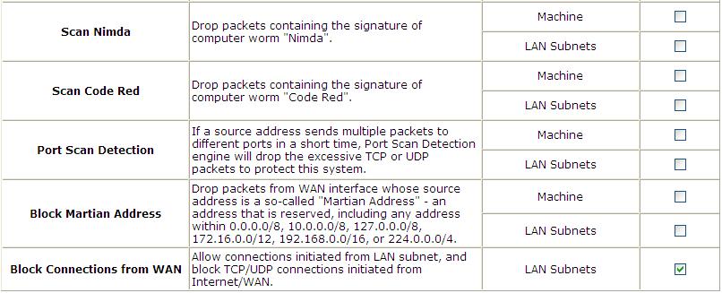
103 103

 if the destination is a single host.")
104 Routing Specific Route Profile: Click the button of Setting for Specific Route Profile, the Specific Route Profile list will appear Specific Route Specific Route Profile: The Specific Default Route is use to control clients to access some specific IP segment by the specified gateway. o o o Destination / IP Address: The destination network address or IP address of the destination host. Please note that, if applicable, the system will calculate and display the appropriate value based on the combination of Network/IP Address and Subnet Mask that are just entered and applied. Destination / Subnet Netmask: The subnet mask of the destination network. Select (/32) if the destination is a single host. Gateway / IP Address: The IP address of the gateway or next router to the destination Default Gateway Default Gateway: The default gateway of WAN1, WAN2, or a desired IP address can be defined in each Policy except Global Policy. When Specific Default Route is enabled, all clients applied with this Policy will access the Internet through this default gateway. o o Enable: Check Enable box to activate this function or uncheck to inactivate it. Default Gateway: It may be WAN1 Default Gateway, WAN2 Default Gateway or to specific an IP Address, if you select IP Address, you may need to fill the IP address of the gateway. 104

105 Schedule Schedule Profile: Click Setting of Schedule Profile to enter the configuration page. Select Enable to show the Permitted Login Hours list. This function is used to limit the time when clients can log in. Check the desired time slots checkbox and click Apply to save the settings. These settings will become effective immediately after clicking Apply. 105
106 Session Limit To prevent ill-behaved clients or malicious software from using up the system s connection resources, the administrator can restrict the number of concurrent sessions that a user can establish. The maximum number of concurrent sessions (TCP and UDP) for each user can be specified in the Global policy, which applies to authenticated users, users on a non-authenticated port, privileged users, and clients in DMZ zones. Also this can be specified in the other policies to apply to the authenticated users. When the number of a user s sessions reaches the session limit, the user will be implicitly suspended upon receipt of any new connection request. In this case, a record will be logged to a Syslog server. Since this basic protection mechanism may not be able to protect the system from all malicious DoS attacks, it is strongly recommended to build some immune capabilities (such as IDS or IPS solutions) in network deployment to maintain network operation. 106


107 7.2. User Access Control WHG Controller supports user access control per service zone, for the entire system, or per authentication server. MAC Access Control per Service Zone Go to Main Menu > System > Service Zones. Each Service Zone s Wireless Settings will be applied to APs that are mapped to this service zone. There is a MAC Access Control section where the administrator can specify up to 10 MAC addresses which can be allowed, denied to access this service zone wirelessly. Access Control Status: Disable means there is no limitation as to what MAC address are allowed or not allowed to access this service zone. Allowed means that only the MAC addresses listed are allowed to access this service zone wirelessly. Denied means that the MAC addresses listed are not allowed to access this service zone wirelessly. Each MAC entry can also be enabled or disabled on the list separately. MAC Access Control for the entire system Go to Main Menu > Users > Additional Control > MAC ACL. The administrator can enter multiple MAC address entries by clicking the Add MACs button. This MAC ACL list is enforced to the whole Controller. Allow means that only the MAC addresses listed are allowed to access the Controller s network. Deny means that the MAC addresses listed are not allowed to access the Controller s network. Disable means that this MAC ACL list is not enforced and that there is not restriction on MAC addresses on the whole system. Black List Go to Main Menu > Users > Black List. 107


108 There are multiple Black List profiles available. Administrator can select one and enforce this black list on the desired authentication server. Click Add User(s) button to fill in usernames (postfix not required). When enforced on an authentication server, accounts in the black list will be denied authentication and network access. Privilege Users Setup the Privilege IP Address List and Privilege MAC Address List. The clients in the list can access the network without any login. 108


109 Privilege IP Privilege IP/IPv6 Address List If there are workstations inside the managed network that need to access the network without authentication, enter the IP addresses of these workstations in the Granted Access by IP Address. The Remark field is not necessary but is useful to keep track. Controller allows 100 privilege IP addresses at most. These settings will become effective immediately after clicking Apply. In addition to granting privileges to just IP addresses, administrator could also specify IP and MAC address sets in this Privilege IP Address List. It is more secure to specify both the IP and MAC address of a privileged client that requires no authentication. Please note, the bandwidth of a client in the Privilege IP Address List will be bounded by the bandwidth limit in the configured QoS Profile. However, the bandwidth of a client in the Privilege MAC Address List will not be bounded at all. Permitting specific IP addresses to have network access rights without going through standard authentication process under service zone may cause security problems. 109

110 Privilege MAC Privilege MAC Address List In addition to the IP address, the MAC address of the workstations that need to access the network without authentication can also be set in the Granted Access by MAC Address. Controller allows specific privilege MAC addresses at most. When manually creating the list, enter the MAC address (the format is xx:xx:xx:xx:xx:xx) as well as the remark (not necessary). These settings will become effective immediately after clicking Apply. Permitting specific MAC addresses to have network access rights without going through standard authentication process under service zone may cause security problems 110
111 7.3. Session Limit & Session Log Session Limit To prevent ill-behaved clients or malicious software from using up system s connection resources, administrators will have to restrict the number of concurrent sessions that a user can establish. The maximum number of concurrent sessions (TCP and UDP) for each user can be specified in each Policy profile, which applies to authenticated users, users on a non-authenticated port, privileged users, and clients in DMZ zones will follow Global policies session limit. When the number of a user s sessions reaches the session limit (a choice of Unlimited, 10, 25, 50, 100, 200, 350, and 500), the user will be implicitly suspended upon receipt of any new connection request. In this case, a record will be logged to the SYSLOG server specified in the & SYSLOG. Since this basic protection mechanism may not be able to protect the system from all malicious DoS attacks, it is strongly recommended to build some immune capabilities (such as IDS or IPS solutions) in the network deployment to protect the network in daily operation. Session Log The system can record connection details of each user accessing the Internet called session log. The log data can be sent out to a specified SYSLOG Server, Box or FTP Server based on pre-defined interval time. The following table shows the fields of a session log record. Field Description Date and Time The date and time that the session is established Session Type [New]: This is the newly established session. [Blocked]: This session is blocked by a Firewall rule. Username The account name (with postfix) of the user; It shows N.A. if the user or device does not need to log in with a username. For example, the user or device is on a non-authenticated port or on the privileged MAC/IP list. Note: Only 31 characters are available for the combination of Session Type plus Username. Please change the account name accordingly, if the name is not identifiable in the record. Protocol The communication protocol of session: TCP or UDP MAC The MAC address of the user s computer or device SIP The source IP address of the user s computer or device SPort The source port number of the user s computer or device DIP The destination IP address of the user s computer or device DPort The destination port number of the user s computer or device 111
112 The following table shows an example of the session log data. Jul 20 12:35: TCP MAC=00:09:6b:cd:83:8c SIP= SPort=1626 DIP= DPort=80 Jul 20 12:35: TCP MAC=00:09:6b:cd:83:8c SIP= SPort=1627 DIP= DPort=80 Jul 20 12:35: TCP MAC=00:09:6b:cd:83:8c SIP= SPort=1628 DIP= DPort=80 Jul 20 12:35: TCP MAC=00:09:6b:cd:83:8c SIP= SPort=1629 DIP= DPort=80 Jul 20 12:35: TCP MAC=00:09:6b:cd:83:8c SIP= SPort=1630 DIP= DPort=80 Jul 20 12:35: TCP MAC=00:09:6b:cd:83:8c SIP= SPort=1631 DIP= DPort=80 Jul 20 12:35: TCP MAC=00:09:6b:cd:83:8c SIP= SPort=1632 DIP= DPort=80 112
113 8. Users Login and Logout 8.1. Before User Login Login with SSL Configure HTTPS; go to: System >> General. HTTPS (HTTP over SSL or HTTP Secure) by means of Secure Socket Layer (SSL) or Transport Layer Security (TLS) encrypts and decrypts user page requests as well as the pages that are returned by the Web server. This function will provide extra security upon client s login. Enable to activate https (encryption) or disable to activate http (non encryption) login page. 113
 standard.")
114 Internal Domain Name with Certificate Configure Internal Domain Name; go to: System >> General >> Internal Domain Name. Internal Domain Name is the domain name of the WHG CONTROLLER as seen on client machines connected under service zone. It must conform to FQDN (Fully-Qualified Domain Name) standard. A user on client machine can use this domain name to access WHG CONTROLLER instead of its IP address. In addition, when Use the name on the security certificate option is checked, the system will use the CN (Common Name) value of the uploaded SSL certificate as the domain name. Configure Certificate; go to: Users >> Additional Control >> Certificate Upload. Certificate: A data record used for authenticating network entities such as a server or a client. A certificate contains X.509 information pieces about its owner (called the subject) and the signing Certificate Authority (called the issuer), plus the owner's public key and the signature made by the CA. Network entities verify these signatures using CA certificates. You can apply for a SSL certificate at CAs such as VeriSign. After Create Root CA, please select Upload Certificate. Click Browse to select the file and upload it. Click Apply to complete the upload process. Without a valid certificate, users may encounter the following problem in IE7 when they try to open the login page. 114
115 Click Continue to this website to access the user login page. To Use Default Certificate: Click Use Default Certificate to use the default certificate and key. Click restart to validate the changes. 115
116 Walled Garden Configure Walled Garden; go to: Network >> Walled Garden. This function provides certain free services for users to access the websites listed here before login and authentication. Specific addresses or domain names of the websites can be defined in this list. Users without the network access right can still have a chance to experience the actual network service free of charge. Enter the website IP Address or Domain Name in the list and click Apply to save the settings. 116


117 Walled Garden AD List Configure Walled Garden AD List; go to: Network >> Walled Garden AD List. This function provides advertisement web pages for users to access free advertisement websites listed before login and authentication. Advertisement hyperlinks are displayed on the user s login page. Clients who click on it will be redirected to the listed advertisement websites. Edit: Click Edit to add a new item or make changes. Click Apply, the items will be added and shown in the list. Display: Choose Display to display advertisement hyperlinks on the login pages 117
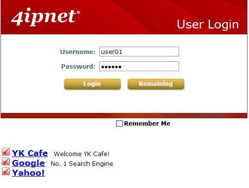
118 118
")
119 Mail Message Configure Mail Message, go to: System >> Service Zones. When enabled, the system will automatically send an to users if they attempt to send/receive their s using POP3 program (for example, Microsoft Outlook) before they are authenticated. Click Edit Mail Message to edit the message in HTML format. 119
120 8.2. After User Login Portal Home Page Configure Home Page Redirect; go to: System >> General. Portal URL function allows the network administrator to specify whether to redirect a user s web browser to a specific webpage or not. When Specific is checked, once a user logged in successfully, user s web browser will be redirected to the specified URL as set in the test box, such as regardless of the original homepage set in their computers. When Original is selected, once a user logged in successfully, user s web browser will be redirected to the homepage URL as set in his browser configurations. When None is selected, once a user logged in successfully, user s web browser will not be redirected to any URL. 120

121 Idle Timer Configure Idle Timer; go to: Users >> Additional Control. If a user has idled with no network activities, the system will automatically kick out the user. The logout timer can be set between 1~1440 minutes, and the default idle time is 10 minutes. 121
122 Multiple Login Configure Idle Timer, go to: Users >> Additional Control. When enabled, a user can log in from different computers with the same account. (This function doesn t support On-demand users and RADIUS authentication.) 122
123 Change Password Privilege Configure Local Users change password privilege; go to: Users >> Group >> Privilege. Privilege Profile: o Change Password Privilege: When Change Password Privilege is enabled, the authenticated users within this Group are allowed to change their password via the Login Success Page. This function is not applicable for on-demand users. 123
124 Proxy Server Configure Proxy Server; go to: Network >> Proxy Server. The system provides a Build-in Proxy Server and External Proxy Server function. After successful authentication, the clients will be redirected back to the desired proxy servers. Basically, a proxy server can help clients access the network resources more quickly. This section presents basic examples for configuring the proxy server settings of WHG CONTROLLER. Using Internet Proxy Server The first scenario is that a proxy server is placed outside the LAN environment or in the Internet. For example, the following diagram shows that a proxy server of an ISP will be used. Follow the following steps to complete the proxy configuration: Step 1. Log into the system by using the admin account. Step 2. Network >> Proxy Server >> External Proxy Servers page. Enable the Built-in Proxy Server. Click Apply to save the settings. 124
, which all users from the Intranet or the Internet are able to access.")


125 Using Extranet Proxy Server The second scenario is that a proxy server is placed in the Extranet (such as DMZ), which all users from the Intranet or the Internet are able to access. For example, the following diagram shows that a proxy server of an organization in the DMZ will be used. Follow the following steps to complete the proxy configuration: Step 1. Log in the system by using the admin account. Step 2. Network >> Proxy Server >> External Proxy Servers page. Select External for Proxy Server. Add the IP address and port number of the Proxy server into External Proxy Servers setting. Click Apply to save the settings. 125
126 9. Local Area AP Management All of the supported APs under management of the system will be shown in this table and listed by different AP type. 126

127 9.1. Multiple Type of AP Besides letting users being connected to the WHG Controller via wired Ethernet cable, you can connect AP to the WHG Controller to extent the network access by wireless. The WHG Controller can manage multiple type of AP, such as, EAP100, EAP-110, EAP-200, EAP-300, EAP700, OWL400, OWL410, OWL500 and OWL510. Almost all the settings of these Local Area APs can be configured from the WHG Controller s WMI. This is because apart from personal or home usage, most other environment typically needs more than one AP to service a lot of clients; places like franchised hotspots, multiple offices, school campuses etc. where in many of these environments it is required to cover both indoor and outdoor areas. Therefore, it is necessary to be able to manage multiple types of APs (Indoor and Outdoor) at the same time. View AP Overview; go to: Access Points >>Enter Local Area AP Management >> Overview. In the Overview page, all of the supported AP type will be listed here. Because the WHG Controller can manage many different models of access points, the easiest way to configure a lot of APs is by AP Template. You can configure one template for each AP model, and then apply this template to many managed APs at once. 127

128 9.2. Configure AP Template Configure AP Template; go to: Access Points >> Enter Local Area AP Management >> Templates. The system supports up to three templates which include configurations of APs. The administrator can configure the setting together in the template instead of logging the AP management interface to set the configurations one by one. Select the AP type (if available) and one of the three available templates, and then click Edit to have the Template Editing page. Input the template Name and Remark for easy reference and memorization. An easy way to configure a template is to copy the configuration of an already configured AP to the template. Select the desired AP from Copy Setting s From list and click apply to copy the selected AP s configuration to the template. If copy is not desired, please select NONE then click the button of Configure to proceed with manual template configuration. Template Editing: The administrator can set the template configuration manually or copy the configurations from a specific existing managed AP by Copy Settings From option. Click Configure button to have detailed configurations. Name: The name shown for this particular template. Copy Settings From: Select a pre-configured existing AP and click Apply to save its settings as the template settings. Remark: The remark or additional information for this template profile. Template Configuration To configure a template manually please click the Configure button. 128
129 General: In this section, revise the Subnet Mask and Default Gateway here if desired. Configure the NTP Servers and Time Zone. In addition, administrator can enable SYSLOG server to receive the log from AP and enable SNMP read/write ability. Wireless: SSID Broadcast: Select this option to enable the AP s SSID to broadcast in your network. It is suggested to disable SSID broadcast feature when you have an authentication disabled network intended for private use. Band: Depending on the AP model template you are editing there are different modes to select, a, b, g, a n, b g and g n. Data Rate: The default is set to Auto. Available range is from 1 to 54Mbps. The rate of data transmission should be set depending on the speed of the wireless network. Select from a range of transmission speed or keep the default setting, Auto, to allow the Access Point to automatically use the fastest rate possible. Preamble: The length of the CRC (Cyclic Redundancy Check) block for communication between the Access Point and roaming wireless adapters. Select either Short Preamble or Long Preamble. IAPP: Inter Access-Point Protocol is designed for the enforcement of unique association 129
130 throughout a ESS (Extended Service Set) and for secure exchange of station s security context between current access point (AP) and new AP during handoff period. Wireless Client Isolation: The default value is Disabled. When Enabled is selected, all the wireless clients will be isolated each other. Transmit Power: The default is Auto. Select from the range or keep the default setting, Auto, to allow the Access Point to automatically adjust transmit power based on AP s loading. Wireless QoS WMM: Select Enabled will allow the packets with QoS WMM processed with higher priority. Fragment Threshold: Breaking a packet into smaller units when transmitting over a network medium that cannot support the original size of the packet. Set the maximum packet size here, packets larger than the configured threshold will be fragmented before transmission. RTS Threshold: Request To Send. When a packet size has reached or exceeded the configured threshold, the computer will need to send a request to send message to the AP. The computer will wait for a CTS (Clear To Send) message before sending data. Beacon Interval (ms): Enter a value between 20 and 1000 msec. The default value is 100 milliseconds. The entered time means how often the beacon signal is transmitted between the access point and the wireless network. 130

131 9.3. AP Discovery Configure Discovery AP; go to: Access Points >> Enter Local Area AP Management >> Discovery. After AP template configuration is complete, use this function to detect and scan for all of the APs connected under the managed network. Note that in Local Area AP Management the WHG Controller can only manage APs that are connected to its LAN ports. Therefore, the AP discovery function is for adding locally connected APs to its management list. The administrator must know the local IP addresses of the APs he/she wishes to discover. Or the alternative is to reset the AP to default setting for discovery. To discover AP: AP Type: Choose the type of AP you wish to discover. Interface: Select which interface to scan. For example if Default is selected, all of the APs connected under default service zone matching the selected AP type will be scanned and listed. Admin Settings Used to Discover: Select Factory Default when the connected AP is under default settings. Select Manual and fill in the IP address range if the connected APs IP address has been modified. Click the Scan Now button and the APs matching the configured criteria will de displayed in the Discovery Results list below. 131


132 Discovery Results: The newly discovered APs will be listed here. When the system s Service Zone is set to Tag-based mode, service zones also can be assigned here. After clicking Add, the current management page is directed to AP List, where the newly added APs will show up in the AP List with a status of configuring. It may take a couple of minutes to see that the status of the newly added AP change from configuring to online or offline. AP Type: The model type of the discovered APs. IP Address: IP address of the specified AP. MAC Address: MAC address of the specific AP. AP Name: Mnemonic name of the specific AP, configurable. Admin Password: Password required for this AP, configurable. Template: Administrator can select a template profile which will be applied to the added AP. Channel: The selected channel will be applied to the added AP. Service Zone: The item is only available for selecting service zone when Tag-Based mode is selected. Add: The administrator can click Add button to register the APs to the List for management. Input the desired name and password for the AP. Select one template, preferred channel, check the Add checkbox and then click Add button to add it under the managed list. When the AP is added, it will show up in the list below and be given a new IP address (depending on which Service Zone it belongs to e.g.: ). 132

133 AP Background Discovery Configure AP Background Discovery; go to: AP Management >> Enter Local Area AP Management >> Discovery. Background AP Discovery: Click Configure to enter Background AP Discovery interface and proceed with related configuration. The configuration is the same as AP Discovery. When Background AP Discovery function is enabled, the system will scan once every 10 minutes or according to the time set by the administrator. If any AP is discovered and Auto Adding AP to the List is enabled, it will be assigned an available IP from the starting IP address set in checked Service Zone profile and applied with the selected template. You can also set the channel of the AP would use. The scanning process may take a long time if the IP range assigned to scan is too wide. 133
134 9.4. Manually add AP Add an AP Manually; go to: Access Points >> Enter Local Area AP Management >> Adding. The administrator can add supported APs into the List table manually here. Similar to the AP added after discovery, a manually added AP will show up with a status of "configuring" in the AP List initially. The system will attempt to configure the AP with the value specified. A couple of minutes later, the AP's status will become "online" or "offline" on the AP List. The AP can also be added manually without being online. Input the related data of the AP and select a Template. After clicking Add, the AP will be added to the managed list. AP Type: The model type of the AP for adding to the List. AP Name: Mnemonic name of the specific AP. Admin Password: Password required for this AP. IP Address: IP address of the specified AP. MAC Address: MAC address of the specific AP. Remark: Some extra information to be filled in for this AP if desired. Service Zone (Tag-Based only): This item is only shown when Tag-Based mode is selected in System Configuration >> LAN Port Mapping. Select the name of Service Zone such as Default, SZ7, etc. And it is only for Multi-VAP AP only. Template Applied: The template which will be applied to the added AP. Channel: The selected channel will be applied to the added AP. 134


135 9.5. AP with Service Zone Configure AP with Service Zone; go to: System >> Service Zones >> Service Zone Configuration. Service Zone Settings Assigned IP Address range for AP Management Under port-based service zone, each service zone can designate an IP segment for IP address assignment to the managed AP when the newly discovered AP is added into the service zone. Under tag-based service zone, only default service zone will designate an IP segment for IP address assignment to the managed AP when the newly discovered AP is added into the selected service zones. Service Zone Settings Managed AP in this Service Zone All managed APs that belong to this service zone are listed here for reference. Service Zone Settings SSID for Service Zone All managed APs that belong to this service zone will be set with the Service Zone s SSID. 135

136 Service Zone Settings Access Control for Service Zone All managed APs (VAP) that belong to this service zone have same ACL table. When the status is Allowed, only these clients whose MAC addresses are listed in this list can be allowed to connect to the AP; on the other hand, when the status is Denied, the clients whose MAC addresses are listed in the list will be denied to connect to the AP. When Disabled is selected, any clients can connect to the AP. The default is Disabled. o User Limit: Limit the number of users connected to an AP managed under this Service Zone. Not all AP types support this option. 136

137 9.6. AP Security Configure AP Security; go to: System >> Service Zones. Security: For each service zone, administrators can set up the wireless security profile, including Authentication and Encryption. Authentication: Including Open System, Share Key, WPA, WPA2 or WPA/WPA2 Mixed. Encryption: WEP: When Authentication is Open System or Share Key, WEP will be enabled. WPA: When Authentication is WPA, WPA-PSK or WPA-RADIUS will be the options of WPA. For WPA-PSK, it also can select Passphrase or HEX. WPA2: When Authentication is WPA, WPA-PSK or WPA-RADIUS will be the options of WPA. For WPA-PSK, it also can select Passphrase or HEX. WPA/WPA2 Mixed: When Authentication is WPA, WPA-PSK or WPA-RADIUS will be the options of WPA. For WPA-PSK, it also can select Passphrase or HEX. 137

138 9.7. Change managed AP settings Configure AP settings in AP List; go to: Access Points >> Enter Local Area AP Management >> List. All of the APs under the management of the WHG Controller will be shown in the list. The AP can be edited by clicking the hyperlink of AP Name and the AP status can be reviewed by clicking the hyperlink of Status. AP Name Click AP Name and enter the interface about related settings. There are four kinds of settings, General Settings, LAN Interface Setting and Wireless Interface Setting. Click the hyperlink to proceed with the configuration of that category. 138

139 General Setting: Click the link to enter the General Setting interface. Firmware information also can be observed here. LAN Setting: Click the link to enter the LAN Setting interface. Administrator can revise the AP s LAN IP settings including IP address, Subnet Mask and Default Gateway of AP. Wireless LAN: Click the link to enter the Wireless interface. Status After clicking the hyperlink in the Status column, there are two areas of information shown: AP Status Summary and AP Status Details. 139

140 AP Status Summary includes AP Name, AP Type, LAN Interface MAC address, Wireless Interface MAC address, Report Time, SSID, and Number of Associated Clients. AP Status Details include System Status, LAN Status, Wireless LAN Status, Associated Client Status and Local Log Status. 140
141 9.8. AP Operations from AP List Configure AP List; go to: Access Points >> Enter Local Area AP Management >> List Reboot, Enable, Disable and Delete the AP Select any AP by checking the checkbox and then click the button below to Reboot, Enable, Disable, Delete, Apply Template and Apply Service Zone (Tag-Based) the selected AP if desired. 141

142 Apply Template Select any AP by check the checkbox and then click Apply Template; select one template to apply to the AP. 142

143 Apply Service Zone (Tag-Based Only) Select any AP by the check the checkbox and then click Apply Service Zone to select which Service Zones this AP associates to. For example, if SZ3 and SZ5 are selected for this AP, then these two Service Zones will be available under this AP. This AP will have two VAPs with two SSIDs according to two Service Zones for clients to associate. If a user connected to one SSID (for example, SSID3) of this AP and wishing to access the Internet, then this user must log into Service Zones (SZ3) first. Check the checkbox to select the available Service Zones from the list. Click Apply to finish the settings. 1. This function only support in Tag-Base mode. 2. Not all AP types support this feature, only Multi-VAP-AP can Apply Service Zone in Tag-Based mode. 143


144 9.9. Firmware management and upgrade Configure Firmware management; go to: Access Points >> Enter Local Area AP Management >> Firmware. The system supports the firmware management of APs to upload new firmware, delete the existing firmware, and download the firmware to managed APs. Note that the AP's firmware version must be one that has been integrated. Firmware Upload displays the current version of the AP s firmware. New firmware can be uploaded here to update the current firmware. To upload, click Browse to select the file and then click Upload. Configure Firmware upgrade; go to: Access Points >> Enter Local Area AP Management >> Upgrade. List: The uploaded firmware will be listed here. File Name: The name of the AP firmware has been uploaded. Checksum: The automatically detected security identification of the firmware. AP Type: The AP type of the firmware. Version: The version of the firmware. Size: The file size of the firmware. Download: Click Download to save the selected firmware to a local disk. Delete: Click Delete to delete the selected firmware from the system. AP Upgrade: Select the APs which need to be upgraded and select the upgrade version of firmware, and click Upgrade to upgrade firmware. 144
 is a function used to connect APs (Access Points) wirelessly.")
145 9.10. WDS Management Configure WDS management; go to: Access Points >> Enter Local Area AP Management >> WDS Management. WDS Management (Wireless Distribution System) is a function used to connect APs (Access Points) wirelessly. The WDS management function of the system can help administrators to setup a Tree structure of WDS network. WDS Status: Status shows the added APs in the WDS Tree with the Security and Channel settings. The WDS could be set up more than one tree. Click the Edit is to change the WDS connection settings for the associated WDS Tree. WDS Update: Update the WDS connection with the following operations. Add: Add a new WDS connection with a Child AP not in the WDS and a Parent AP from the AP List. A new WDS Tree will be added if the selected Parent AP is not in any of the current WDS Trees. Click Edit is to change the WDS connection settings for the new added WDS Tree. Move: Update a WDS connection with a Child AP from WDS and a Parent AP which could be anymore from WDS, and the previous WDS connection of the Child AP to the previous Parent AP will be deleted. Delete: All the WDS connections of the selected AP will be deleted including the WDS connections to its Child APs, and the Child APs without wired connection will become unreachable. 145

146 9.11. Rogue AP Detection Configure Rough AP Detection; go to: Access Points >> Enter Local Area AP Management >> Rogue AP Detection. It is designed to detect the non-managed or possibly malicious AP in the deployed environment. It takes the managed APs as sensors to find out the non-managed AP even if the AP uses the same SSID with managed AP's. It shows the AP's BSSID, ESSID, Type, Channel, Encryption, and found time. 1. Setup the Detection Interval Configure Detection Interval; go to: Access Points >>Rogue AP Detection >>General Configuration. Input a Detection Interval, if you input 0, it will Disable this function, and system will not enable the Rogue AP Detection function. 2. Let the managed AP be the sensor Configure Rogue AP Sensor; go to: Access Points >>Rogue AP Detection >>Sensor List Configuration. Before setup the AP sensor, you must discovery the APs and apply template first. Note: For more detail of AP Management, please refer to the section of Managing Wireless Network. 146


147 Basically, all of the managed AP can become a Rogue AP sensor, but some earlier version AP will not support this function, they will list in the Sensor List, but they are not available for selection, so the Sensor List will list all of the managed AP. Select the APs and click Apply. 3. Add the non-managed AP to the Trust List Configure Trust AP List; go to: Access Points >>Rogue AP Detection >>Trusted AP Configuration. After the AP detection is finished. All of the non-managed AP will show in the List. If there are some APs that are trusted by administrator, or these APs are just temporary usage. So you can add these APs to the Trust List, and then system will ignore these APs and will not show in the Rogue AP List again. Also you can check which AP had added to trust list by the Trusted AP List. 147


148 9.12. AP Load Balancing Configure AP Load Balancing; go to: Access Points >> Enter Local Area AP Management >> AP Load Balancing. It is a function to prevent managed APs from overloading. When the system detects the occurrence of APs' associated-client numbers exceeding a predefined threshold at circumstances other APs in the same group are still below the threshold, the balancing function will be activated to decrease the overloading APs' transmit power and increase other available APs' transmit power; this will let other available APs have more chance to be associated. The system can divide the managed APs into groups; define the group threshold, and a time interval which will trigger the AP load balancing. AP Load Balancing Page Editing General Configuration Page Editing Group Configuration Page 148


149 1. Setup the Interval Configure Interval; go to: Access Points >>AP Load Balancing. Go to: Access Points >>AP Load Balancing >> Configuration. Input an Interval, if you input 0, it means Disabled, and system will not enable the AP Load Balancing function. 2. Configure the Loading of Threshold of each Group Configure Group Configuration; go to: Access Points >>AP Load Balancing >>Group Configuration. You can choose the Loading Threshold of each group. Also you can disable the AP group, if the group is disabled; this group of AP will not enable the Load Balancing function. 3. Add the AP to the Group Configure AP to the Group; go to: Access Points >>AP Load Balancing >>Device List. 149

150 Before setup the AP Load Balancing, you must discovery the APs and apply template first. Note: For more detail of AP Management, please refer to the section of Managing Wireless Network. All of the managed AP can join to any of the Load Balancing Group, so the Device List will list all of the managed AP. Select the APs, chose a Group and click Apply. The APs will join into this group. If the overloading is happened, you can check the Power Level from this List. It will record the changing process, such as, Highest to High ; Low to Medium. Note: It is strongly recommended that don t choose different type of AP to create the Load Balance Group. 150

151 10. Wide Area AP Management The WHG Controller supports the planning and monitoring of Access Points deployed over complicated network structures such as the internet. Integrated with Google Map API, Wide Area AP Management provides intuitive graphical tools for mapping APs at various physical locations and keeping track of these devices. Under Wide Area AP management, you can choose to simply monitor AP s status via SNMP or logically incorporate LevelOne APs into the WHG Controllers managed network via tunnels. AP models supported for Wide Area AP management include OWL800, EAP-200, EAP-110, EAP-300 and 3rd party AP. Please note that different WHG models may support different LevelOne AP models, please refer to datasheet for AP models supported. 151

152 10.1. AP Discovery Discover connected APs; go to: Access Points >> Enter Wide Area AP Management >> Discovery. With the Discovery feature, administrator can scan for APs regardless of their physical location as long as their IP address can be reached. After the discovery process, newly found AP s will be listed under Device Results allowing administrators to add it to the managed AP List. Start / End IP address: Administrator need to specify the IP address range for AP discovery, and the specified IP address can be external or internal network IP addresses. This is useful when scanning for multiple devices connected to the managed network. APs with an IP address that is not within the specified range will not be listed after discovery. Login ID / Password: Fill in the Login ID and Password of the target AP s management interface, this will allow the administrator to remotely configure the AP s SNMP community. Discover: When the administrator tries to discover a new AP, select the Device Type. Second, enter the current IP range of the APs, Login ID and Password. Then click Discover button. If the new AP has been discovered, it will appear in the following Discovery Results list. Device Results: The discovery new APs will be listed here. The administrator can click Add to register the APs to the List for management. When the discovery process is complete, the APs found will be listed under Device Results table. Here the administrator can specify the individual APs Device Name and SNMP Community string. Click the Add button and the discovered APs will be added into List. 152

153 10.2. Manually add AP Add an individual Access Points to the managed list; go to: Access Points >> Enter Wide Area AP Management >> Adding. Besides Discovery feature that can search and list multiple APs for adding to the management list, Adding page allows administrator to directly add a single Access Point to the management list. Simply configure the devices IP address, name and login credentials, set a SNMP community string and click the Add button. Device Type: The device type of Wide Area APs. Device IP: The IP address of the AP to add to the management list. Device Name: The mnemonic name given to this AP device. Login ID: The Device s management interface login name. Password: The Device s management interface login password. SNMP Community: The SNMP Read Community string used for status access. 153


154 10.3. Manage AP Lists Manage AP lists; go to: Access Points >> Enter Wide Area AP Management >> List. When an EAP-200 is discovered or added to the AP list, it can be logically deployed into the WHG Controller s managed network regardless of its physical location by tunnels. Initially when an AP has been successfully added to the List, it s Tunnel Status will show a red light indicating that no tunnel is established and that this AP is only being monitored via SNMP. If you wish to create a tunnel between this AP and the WHG Controller, click the Edit button to proceed with necessary configurations. In the AP s tunnel configuration page, check Enable, set a numerical authentications key between WHG Controller and AP. Click Apply to create tunnel. A new window will automatically open and display the tunnel settings on the AP side which is passed from the WHG Controller. Click the Reboot link to apply and activate the settings. Once the AP has completed the reboot process, the tunnel will be in effect as shown in the APs Status >> Overview page. 154


155 AP s tunnel settings can be checked at System >> Management page. On the WHG Controller side, the AP s Tunnel status will show green light indicating an active tunnel has been set up between WHG Controller and AP. Now the administrator can click Edit and re-enter the Tunnel Status page to assign a Service Zone to this tunnel managed AP. VAP status will display all the enabled VAP on the remote EAP-200 with their respective ESSID and VLAN ID. An enabled Service Zone can be applied to each VAP entry and users associated to ESSID of this VAP will be governed by the applied service zone as if under the WHG Controller s managed internal network. 155


156 10.4. Manage Third Party AP Add a third party AP; go to: Access Points >> Enter Wide Area AP Management >> List. Add third party AP by selecting THIRDAP from Device Type. Add to AP List manually by specifying third party AP s IP address, Name, and VLAN ID. Click Add to finish adding and check lists to List icon. Check and Manage List of third Party AP; go to: Access Points >> Enter Wide Area AP Management >> List. Manage this third party AP from the Type Lists. Edit its AP Attribute and Administration from the column. Go to Map icon. The added third party AP could be placed on Google Map feature and all map function. Create graphical reports for data traffics passing through this third party AP. Configure third party AP to maps; go to: Access Points >> Enter Wide Area AP Management >> Map. 156

157 10.5. Map Configure maps; go to: Access Points >> Enter Wide Area AP Management >> Map. The Map tab page is implemented with Google Map API version2 which allows administrators to view at a glance the whereabouts of all of the AP s under Wide Area AP Management. This feature is helpful when it comes to network planning and management. Once the administrator has added APs to the managed list, then these APs can be tagged or marked on the Google Map API to show its geographical location, as shown below: Procedure to create a Map: Step 1: Get a Public IP Address from your ISP and configure this address to WAN interface. Step 2: Apply for a Google Maps Registration key. Step 3: Click Add a New Map button on the Map page. Configure Map Name and registration key. Step 4: Discover APs and Add these AP to managed List. Step 5: From the List page, add some APs to the created Map. The necessary steps required to configure your map with AP information are described in the subsequent sections. 157


158 Register key from Google Before configuring your maps, you will need to register the WHG Controller s IP address at Google Maps and get a key from Google. Go to or search for Google Map API, to enter the Google code page. Click on Sign up for a Google Maps API key. Click the terms and condition check box and fill in your WHG Controller s WAN IP address. Google will generate an API key for your WHG Controller. 158


159 Create a Map Now, return to the Map tab page in WHG Controller s WMI and Scroll down to the bottom of the page, click on the Add a New Map button. An editing page will open for configuration, please fill in a Map Name for this map and its geographical location as defined by Longitude and Latitude, remember to also fill in the Key issued by Google. Finally choose the Zoom Level and Map Type and click the Save button. The above screenshot is an example showing Taipei City with Map Name as Taipei Bridge, Zoom Level of 14 and Normal Map Type. 159

160 Marking APs on your Map If you have several APs deployed and listed in List under Wide Area AP Management, their geographical location can be marked on a particular map. Firstly, go to the List tab page and click on the Edit button of the AP s that you wish to mark in the map. In the AP configuration page, set the coordinates (Latitude and Longitude) of this AP and the radius of signal coverage. Fill in the coordinates where you wish to mark this particular AP. Link 1 ~ Link 3 is for configuring a http link that will show up in the dialogue box on the map for referencing additional information related to this AP, for instance the IP address of a IP surveillance camera connected to this AP or the URL of the Venue Website where this AP is deployed. Administrator can upload customized thumbnail image shown in the map. After configuring all the necessary settings and uploading your images, click Save button and return to AP List page. Check the AP s that you wish to mark in the map and click the Add to Map button, choose the name of the map on which you wish to mark these APs and click OK button. 160


161 The selected APs will show up as marker images on the map at the physical coordinates configured, as shown below. You can click on the AP icon to see the dialogue box for additional information or links that you have configured. Click the more info link for information on AP status, Client List, WDS List and Links related to this AP. 161

162 AP status, Client List and WDS List information listed are collected from the remote AP via SNMP. 162
163 Operations from Map page Goto Map: When you have configured multiple map profiles, this function allows switching between different maps. Goto AP: This function is for administrator to select an AP on the list, and the map will shift to show the selected AP in the center of the map. Show Coverage: This button once pressed will display the signal coverage of all the APs on the map according the coverage radius set in each AP s profile under List tab page. Show Longitude and Latitude: This function when pressed will display in a pop up window the longitude and latitude of the map s current center point. Save Modification: This function is for saving the changes made to the map and overwriting the maps profile attributes. For instance if you have altered or panned the original map, clicking this button will save the changes made. List AP in this Map: Clicking this button will open a new page on your browser redirecting to the List tab page for displaying a list of APs in the Map. List WDS in this Map: Clicking this button will open a new page on your browser redirecting to the WDS List tab page for displaying a list of WDS links in the Map. Delete this Map: Delete the current map profile. Add a New Map: Click to add a new map profile. Edit this Map: Click to modify the current map s attribute settings. Customize Image: Administrator can upload desired images for each AP model that will be used as AP markers on the MAP. 163


164 10.6. AP Operations from AP List Perform operations on managed APs; go to: Access Points >> Enter Wide Area AP Management >> List. After adding APs to the managed List, the List page provides some operations for managing the listed AP s. Goto: The WHG Controller cannot directly configure Wide Area AP s settings remotely. However, the Goto button is a convenient link for accessing the remote AP s WMI. Please note that the Goto button will only become active when the listed AP s status is Online. The drop down list on the column header is for specifying which WMI page to go to. Edit (AP Attribute): Click this button to enter the AP s attribute editing page where administrator can specify the Device Name and SNMP community. If the AP is to be marked on a map, this page also allows administrator to configure the geographical location, coverage, related links and customize marker or icon images that will be displayed on the map. Edit (Tunnel Status): Only applicable to EAP-200 APs. Click this button to setup a secure tunnel between the WHG Controller and the listed EAP-200. Once the tunnel has been established, the AP can be seen as logically connected under the WHG Controllers managed network and can be applied a Service Zone. Delete: Remove the checked AP from the List. Add to Map: Clicking this button will open a popup window. Administrator can Mark the selected APs on the Map chosen from the drop down list. If no map profile has been configured, there will be no available map to choose in the drop down list. Backup Config: Clicking this button will open a popup window where administrator can backup the chosen AP s configuration settings into a.db file store in the WHG Controller s memory. The Backup up files are listed under Backup Config tab page for download or deletion. Restore Config: Clicking this button will open a popup window where administrator can restore the 164
165 chosen AP s configuration settings using a.db file store locally in administrator PC or in the WHG Controller s memory. Upgrade: Clicking this button will open a popup window where administrator can upgrade the chosen AP s firmware using a firmware file store locally in administrator PC or in the WHG Controller s memory (under Firmware tab page). 165

166 10.7. WDS List View the WDS link information established between APs in Wide Area AP Management; go to Access Points >> Enter Wide Area AP Management >> WDS List. The WDS link if established between APs listed in List will be listed here with related information such as the Band and Channel of the link, Security settings if any and the Transmit Power, Byte, Packets etc. 166
167 10.8. Backup Config View previously saved backup files for Wide Area APs; go to: Access Points >> Enter Wide Area AP Management >> Backup Config. Backed up Config files can be used to restore an AP s settings in List. When administrator backups an AP s configuration settings, all the backup files are listed at the Backup Config tab page and can be downloaded to a local storage device or deleted from WHG Controller s memory. 167

168 10.9. Firmware management and upgrade Upload or view the details of previously uploaded firmware for upgrading APs; go to: Access Points >> Enter Wide Area AP Management >> Firmware. The WHG Controller can store AP s firmware in its built-in memory. Under the Firmware tab page administrator can upload new AP firmware to the WHG Controller s memory allowing for easy remote AP upgrade and restore operations from the AP List page. The AP firmware listed under this page can be downloaded or deleted from WHG Controller memory if desired. 168

169 CAPWAP Enable CPAWAP auto-discovery feature for supported AP s; go to: Access Points >> Enter Wide Area AP Management >> CAPWAP. CAPWAP is a standard interoperable protocol that enables a WHG Controller to manage a collection of wireless access points. Status: The configuration status of CAPWAP function. Click Enable to open the Access WHG Controller to allow CAPWAP supported AP s to automatically add to the managed AP List. Restore Configuration: Currently EAP-200 and EAP-300 are the AP models that support the CAPWAP feature. Once an AP is added to the list and is manually configured, its configuration profile can be backed up in the AC memory and will be selectable in the drop down menu. When a configuration profile is selected here, whenever an AP of this model is automatically discovered and added to the managed List, that AP will be configured with the configuration profile selected here. Template: This configuration item allows the administrator to specify which of the VAP profiles on the AP are allowed DTF (Distributed Traffic Forwarding) once it is discovered and managed by the AC. It enables the administrator to statically assign which VAPs are to be tunneled back to AC and what SZ they service, unassigned VAPs will service by DTF where the client traffic will not be tunneled back to AC, but directly to the internet instead. Certificate: This configuration item allows the administrator to select which of the certificates will be used during CAPWAP negotiation between AC and AP. If the certificate selected is invalid, the negotiation will be unsuccessful and the AP will not be automatically added in the managed List. WHG Access Controller IP List: The AC can statically designate other CAPWAP supported ACs as backup AC for CAPWAP APs in case it can no longer provide service. The No. designates the priority of these backup ACs to the AP, in the event that the original AC is down, the AP will first attempt to join the No. 1 backup AC and so on. 169
 to External IP address (WAN) mapping in the Static Assignments.")
170 11. Networking Features of a Gateway DMZ Configure DMZ; go to: Network >> NAT >> DMZ (Demilitarized Zone). The system supports specific sets of Internal IP address (LAN) to External IP address (WAN) mapping in the Static Assignments. The External IP Address of the Automatic WAN IP Assignment is the IP address of External Interface (WAN1) that will change dynamically if WAN1 Interface is Dynamic. When Automatic WAN IP Assignments is enabled, the entered Internal IP Address of Automatic WAN IP Assignment will be bound with WAN1 interface. Each Static Assignment could be bound with the chosen External Interface, WAN1 or WAN2. There are specific sets of static Internal IP Address and External IP Address available. Enter Internal and External IP Addresses as a set. After the setup, accessing the WAN will be mapped to access the Internal IP Address. These settings will become effective immediately after clicking the Apply button. 170

171 11.2. Virtual Server Configure Virtual Server; go to: Network >> NAT >> Public Accessible Server. This function allows the administrator to set virtual servers, so that client devices outside the managed network can access these servers within the managed network. Different virtual servers can be configured for different sets of physical services, such as TCP and UDP services in general. Enter the External Service Port, Local Server IP Address and Local Server Port. Select TCP or UDP for the service s type. In the Enable column, check the desired server to enable. These settings will become effective immediately after clicking the Apply button. 171


172 11.3. Client Mobility Configure IP Plug and Play; go to: Network >> Client Mobility. WHG CONTROLLER supports IP PNP function: users can login and access network with any IP address setting. At the user end, a static IP address can be used to connect to the system. Regardless of what the IP address used at the user end, authentication can still be performed through WHG CONTROLLER. IP PNP: When IP PNP is enabled, a PC with a static IP address can still access the network even the system enables built-in DHCP server. No TCP/IP reconfiguration is needed. Cross Gateway Roaming: Configure this gateway to Master or Slave. In Master mode, you may also need to input the Slave IP and Secret Key. In Slave Mode, input Master IP and Key. Master Node: While configure Master Node, one master could active up to 15 Slave node setting. Slave Node: While configure Slave Node, enter its master node setting. 172

173 11.4. DNS Cache Configure DNS Cache; go to: Network >> DNS Cache. The administrator could statically assign Domain Name to IP mappings for all clients connected to the WHG Controller s LAN network. This feature can be used to redirect clients to preferred IP address for certain Domain Names. 173

174 11.5. Dynamic Domain Name Service Configure Dynamic Domain Name Service; go to: Network >> DDNS. Before activating this function, you must have your Dynamic DNS hostname registered with a Dynamic DNS provider. WHG CONTROLLER supports DNS function to alias the dynamic IP address for the WAN port to a static domain name, allowing the administrator to easily access WHG Controller s WAN. If the dynamic DHCP is activated at the WAN port, it will update the IP address of the DNS server periodically. These settings will become effective immediately after clicking Apply. DDNS: Enable or disable this function. Provider: Select the DNS provider. Host name: The IP address/domain name of the WAN port. Username/ The register ID (username or ) for the DNS provider. Password/Key: The register password for the DNS provider. Note: To apply for free Dynamic DNS service, you may go to 174

175 11.6. Port and IP Forwarding Configure Port and IP Redirect; go to: Network >> NAT >> Port and IP Forwarding. This function allows the administrator to set specific sets of the IP addresses at most for redirection purpose. When the user attempts to connect to a destination IP address listed here, the connection packet will be converted and redirected to the corresponding destination. Please enter the IP Address and Port of Destination, and the IP Address and Port of Translated to Destination. Select TCP or UDP for the service s type. These settings will become effective immediately after clicking Apply. 175


176 11.7. Dynamic Route Configure Dynamic Route; go to: Network >> Dynamic Route. The function supports three dynamic routing protocols: RIP, OSPF and IS-IS. RIP Configuration: It is a dynamic routing protocol used in local and wide area networks. You can configure each interface to be Passive, supportive version and authentication. Passive: RIP packets will not be sent from network interfaces that are checked as Passive. Version: Select the RIP version for this interface, RIPv1 uses broadcast to deliver RIP packets, RIPv2 uses Multicast to deliver RIP packets, both uses broadcast and multicast. AUTH: AUTH: Allows the authenticating of RIP neighbors. The authentication method "none" means that no authentication is used for RIP and it is the default method. The two modes of authentication on an interface for which RIP authentication is enabled: plain text authentication and MD5 authentication. Advertise I am Default Gateway: Inform neighboring nodes that this controller is the default gateway. Advertise Global Policy Route: Inform neighboring nodes the Global Policy route on this controller. Redistribute OSPF: Check this option to enable using RIP to distribute routing information acquired via OSPF. RIP Timer: Update timer: Specify the time in seconds when the system will request for immediate update in 176

177 routing information. Timeout Timer: Routes are only kept in the routing table for a limited amount of time. A special Timeout timer is started whenever a route is installed in the routing table. Whenever the router receives another RIP Response with information about that route, the route is considered refreshed and its Timeout timer is reset. When this timer expires, the route is marked as invalid. Garbage Collection Timer: Specify the time in seconds before erasing invalid route from the routing table. OSPF Configuration: It is an adaptive routing protocol for Internet Protocol (IP) networks. You can configure each interface Area, Stub and authentication. Area: An Area is a set of networks and hosts within a routing domain that have been administratively grouped together. Area 0, known as the backbone area, resides at the top level of the hierarchy and provides connectivity to the non-backbone areas (numbered 1, 2). Stub Area: Are areas through which or into which AS external advertisements are not flooded. AUTH: Allows the authenticating of OSPF neighbors. The authentication method "none" means that no authentication is used for OSPF and it is the default method. With MD5 authentication, enter the MD5 password, the password does not pass over the network. Advertise I am Default Gateway: Inform neighboring nodes that this controller is the default gateway. Advertise Global Policy Route: Inform neighboring nodes the Global Policy route on this controller. Redistribute RIP: Check this option to enable using OSPF to distribute routing information acquired via RIP. ISIS Configuration: It is a routing protocol designed to move information efficiently within a computer network, 177

178 a group of physically connected computers or similar devices. You can configure each interface Circuit Type to Level 1 or Level 2. Net ID: It is the ISO address Network Entity Title (NET). The NET is used just like an IP address to uniquely identify a router on the inter-network. Circuit Type: Level 1 systems route within an area; when the destination is outside an area, they route toward a Level 2 system. Level 2 intermediate systems route between areas and toward other routing domains. The level type of each network interface can be assigned. 178
179 12. System Management and Utilities System Time Configure System Time; go to: System >> General NTP NTP (Network Time Protocol) communication protocol can be used to synchronize the system time with remote time server. Please specify the local time zone and the IP address of at least one NTP server for adjusting the time automatically (Universal Time is Greenwich Mean Time, GMT). 179
180 Manual Settings The time can also be manually configured by selecting Manually set up and then entering the date and time in these fields. 180

181 12.2. Management IP Configure Management IP; go to: System >> General. Only PCs within this IP range on the list are allowed to access the system's web management interface. For example, /24 means that as long as an administrator is using a computer with the IP address range of /24, he or she can access the web management page. Another example is : if an administrator is using a computer with the IP address of , the user can access the web management page. The default value is / It means that the WMI can be accessed by any IP address, for security consideration; please change this value before the system provides service. 181


182 12.3. Access History IP Configure Access History IP; go to: System >> General. Specify an IP address of the administrator s computer or a billing system to get billing history information of WHG CONTROLLER with the predefined URLs. The file name format is yyyy-mm-dd. An example is provided as follows: Traffic History: On-demand History: 182

183 12.4. SNMP Configure SNMP; go to: System >> General. If this function is enabled, the SNMP Management IP and the Community can be assigned to access the SNMP Configuration List of the system. 183

184 12.5. Change Password Configure Change Password; go to: Utilities >> Password Change. There are three levels of authorities: admin, manager or operator. The default usernames and passwords are as follows: Admin: The administrator can access all configuration pages of WHG CONTROLLER. User Name: admin Password: admin Manager: The manager can only access the configuration pages under User Authentication to manage the user accounts, but without permission to change the settings of the profiles of Firewall, Specific Route and Schedule. User Name: manager Password: manager Operator: The operator can only access the configuration page of Create On-demand User to create new on-demand user accounts and print out the on-demand user account receipts. User Name: operator Password: operator The administrator can change the passwords here. Please enter the current password and then enter the new password twice to verify. Click Apply to activate this new password. Note: Only login with admin can change password. If the administrator s password is lost, the administrator s password still can be changed through the text mode management interface at the serial console port. 184


185 12.6. Backup / Restore and Reset to Factory Default Configure Backup / Restore and Reset to Factory Default; go to: Utilities >> Backup & Restore. This function is used to backup/restore the WHG CONTROLLER settings. Also, WHG CONTROLLER can be restored to the factory default settings here. Backup System Settings: Click Backup to create a.db database backup file and save it on disk. Restore System Settings: Click Browse to search for a.db database backup file created by WHG CONTROLLER and click Restore to restore to the same settings at the time when the backup file was saved. The option of Keep WAN1 setting and Management IP Address List can be selected to retain WAN1 setting for remote access. Reset to Factory Default: Click Reset to load the factory default settings of WHG CONTROLLER. 185

186 12.7. Firmware Upgrade Configure Firmware Upgrade; go to: Utilities >> System Upgrade. The administrator can download the latest firmware from website and upgrade the system here. Click Browse to search for the firmware file and click Apply for the firmware upgrade. It might take a few minutes before the upgrade process completes and the system needs to be restarted afterwards to activate the new firmware. FTP firmware upgrade is also an option, enter the FTP server IP address, FTP server port, and the FTP account name and password, and lastly specify the complete firmware filename stored on the FTP server that will be used to upgrade the system. 1. Firmware upgrade may cause the loss of some data. Please refer to the release notes for the limitation before upgrading. 2. Please restart the system after upgrading the firmware. Do not power on/off the system during the upgrade or restart process. It may damage the system and cause malfunction. 186
187 12.8. Restart Configure Restart; go to: Utilities >> Restart. This function allows the administrator to safely restart WHG CONTROLLER, and the process might take approximately three minutes. Click YES to restart WHG CONTROLLER; click NO to go back to the previous screen. If the power needs to be turned off, it is highly recommended to restart WHG CONTROLLER first and then turn off the power after completing the restart process. The connection of all online users of the system will be disconnected when system is in the process of restarting. 187
188 12.9. Network Utility Configure Network Utility; go to: Utilities >> Network Utilities. The system provides some network utilities to help administrators manage the network easily. 188
189 Item Description Wake-on-LAN It allows the system to remotely boot up a power-down computer with Wake-On-LAN feature enabled in its BIOS and it is connect to any service zone. Enter the MAC Address of the desired device and click Wake Up button to execute this function. IPv4 Ping: It allows administrator to detect a device using IP address or Host domain name to see if it is alive or not. Trace Route: It allows administrator to find out the real path of packets from the gateway to a destination using IP address or Host domain name. ARPing: Allows the administrator to send ARP request for a specific IP address or domain name. ARP Table: It allows administrator to view the IP-to-Physical address translation tables used by address resolution protocol (ARP). IPv6 Ping: It allows administrator to detect a device using IPv6 address or Host domain name to see if it is alive or not. Trace Route 6: It allows administrator to find out the real path of packets from the gateway to a destination using IPv6 address or Host domain name. Neighbor Discovery: The administrator can use this feature to learn about IPv6 Neighbor nodes that are on the same IP segment or domain name. Neighbor Cache: a node manages the information about its neighbors in the Neighbor Cache. This feature allows the administrator to view the information stored on system s neighbor cache. Sniff With this feature the administrator can listen for packets from selected Interfaces. The administrator can further filter the types of packets to capture by using tcpdump commands under the Expression field. Status When the administrator is executing any Network Utilities features, the status of the operation is displayed here. Result The operation result is displayed here. 189


190 Certificate Configure Certificate Utility; go to: Utility >> Certificate. AC can issue certificates to APs that it manages in its private network. Administrator can sign certificates issues by the system s root CA and load these certificates to managed APs. These APs will be used in verifying the identity and authenticity of CAPWAP discovery requests between AP and AC. Get CERT: Download Certificate, Get Key: Download Key. 190


191 Create System s Root CA Administrator can create a root CA for private use. The created root CA certificate can be downloaded and used to sign certificates generated by the system. The created root CA will be displayed in the table below. Signing Certificates with System Root CA When a root CA has been created, the Create Root CA option in the drop down list will become Signed by Root CA. Certificate information entered and Applied will be used to generate an issued certificate from root CA. 191

192 The generated certificate will be listed in the My Issue Certificate table. Certificate and key can be downloaded with Get Cert, Get key button. Uploading Certificate or Trusted CA Apart from self signed certificate and system s root CA, administrators can also upload other certificates signed by other CA entities or Trusted CAs into the system. Select Upload Certificate to browse and upload a selected Certificate and Key into the System. Select Upload Trust CA to browse and upload a trusted CA certificate into the System. 192
193 Administrator Account Configure operator accounts; go to: Utilities >> Administrator Account. WHG Controller has three kinds of permanent management account: admin, manager or operator. The default usernames and passwords show as follows: Admin: The administrator can access all configuration pages of WHG Controller and has all modification and access privilege. User Name: admin Password: admin Manager: The manager can only access the configuration pages under User Authentication to manage the user account, it does not have the permission to change the settings of the profiles of Firewall, Specific Route and Schedule. User Name: manager Password: manager Operator: The operator can only access the configuration page of Create On-demand User to create new on-demand user accounts and print out the on-demand user account receipts. User Name: operator Password: operator Note: To logout, simply click the Logout icon on the upper right corner of the interface to return to the login screen. Besides permanent Administrator, Manager, and Operator accounts, different operator accounts can be created with different levels of authority and access for managing the Service Zones and APs they are in charge of. 193


194 Create Admin Account Different operator accounts and their password can be specified here. Group here are authorization profiles that will be applied to this operator account, each Group profile can specify which SZ this account can access and the Maps that this operator can access. Administrator can enter the desired user account name and password, select an authorization Group profile and Apply. The created operator account, password, group and status will be shown in the Admin List below. 194


195 Configure operator Group profile Group allowed SZ and Map can be configured here. In this configuration page, administrator can specify which Service Zone and Map are allowed to be accessed by the operator that belongs to this Group. This feature allows the administrator to create multi-level privilege accounts with flexibility to meet the deployment and management needs. When an operator logs into the system with a created account, he will only be able to access the Service Zone profiles checked in the Group profile he belongs to and he can only see the Map and only the APs marked on the checked Maps in the managed AP list. 195

196 Monitor IP Configure Monitoring 3 rd Party IP; go to: Network >> Monitor IP. WHG CONTROLLER will send out a packet periodically to monitor the connection status of the IP addresses on the list. On each monitored item with a WEB server running, administrators may add a link for the easy access by entering the IP, select the Protocol to http or https and then click Create. After clicking Create button, the IP address will become a hyperlink, and administrators can easily access the host by clicking the hyperlink remotely. Click the Delete button to remove the setting. Monitoring 3 rd Party AP, go to: Network >> Monitor IP. If you are using 3 rd party AP, you can use Monitor IP function to monitor the AP connection status. Because WHG CONTROLLER can not manage these APs, Monitor IP is a better way to monitor the AP connection status. WHG CONTROLLER will send out a packet periodically to monitor the connection status of the IP addresses on the list. If the monitored IP address does not respond, the system will send an to notify the administrator that such destination is not reachable. After entering the necessary information, click Apply to save the settings. Click Monitor Now to check the current status of all the monitored IP. The system supports monitoring on 200 IP addresses listed in the Monitor IP List. 196


197 Console Interface Via this port to enter the console interface for the administrator to handle the problems and situations occurred during operation. 1. In order to connect to the console port of WHG CONTROLLER, a console, modem cable and a terminal simulation program, such as the Hyper Terminal are needed. 2. If a Hyper Terminal is used, please set the parameters as 9600, 8, None, 1, None. The main console is a menu-driven text interface with dialog boxes. Please use arrow keys on the keyboard to browse the menu and press the Enter key to make selection or confirm what you enter. 3. Once the console port of WHG CONTROLLER is connected properly, the console main screen will appear automatically. If the screen does not appear in the terminal simulation program automatically, please try to press the arrow keys, so that the terminal simulation program will send some messages to the system, where the welcome screen or main menu should appear. If the welcome screen or main menu of the console still does not pop up, please check the connection of the cables and the settings of the terminal simulation program. 197
: By sending ICMP echo request to a specified host and wait for the response to test the network status.")
198 Utilities for network debugging The console interface provides several utilities to assist the Administrator to check the system conditions and to debug any problems. The utilities are described as follows: Ping host (IP): By sending ICMP echo request to a specified host and wait for the response to test the network status. Trace routing path: Trace and inquire the routing path to a specific target. Display interface settings: It displays the information of each network interface setting including the MAC address, IP address, and Netmask. Display the routing table: The internal routing table of the system is displayed, which may help to confirm the Static Route settings. Display ARP table: The internal ARP table of the system is displayed. Display system up time: The system live time (time for system being turn on) is displayed. Check service status: Check and display the status of the system. Set device into safe mode : If the administrator is unable to use Web Management Interface via browser for the system failed inexplicitly. The administrator can choose this utility and set it into safe mode, which enables him to manage this device with browser again. Synchronize clock with NTP server: Immediately synchronize the clock through the NTP protocol and the specified network time server. Since this interface does not support manual setup for its internal clock, therefore we must reset the internal clock through the NTP. Print the kernel ring buffer: It is used to examine or control the kernel ring buffer. The program helps users to print out their boot-up messages instead of copying the messages by hand. Main menu: Go back to the main menu. Change admin password Besides supporting the use of console management interface through the connection of null modem, the system also supports the SSH online connection for the setup. When using a null modem to connect to the system console, we do not need to enter administrator s password to enter the console management interface. But connecting the system by SSH, we have to enter the username and password. 198
199 The username is admin and the default password is also admin, which is the same as for the web management interface. Password can also be changed here. If administrators forget the password and are unable to log in the management interface from the web or the remote end of the SSH, they can still use the null modem to connect the console management interface and set the administrator s password again. Although it does not require a username and password for the connection via the serial port, the same management interface can be accessed via SSH. Therefore, we recommend you to immediately change the WHG CONTROLLER Admin username and password after logging in the system for the first time. Reload factory default Choosing this option will reset the system configuration to the factory defaults. Restart WHG CONTROLLER Choosing this option will restart WHG CONTROLLER. 199

200 13. System Status and Reports View the Status This section includes System Status, Interface Status, Hardware, Routing Table, Online Users, Session List, User Logs, Logs, DHCP Lease, and & Syslog to provide system status information and online user status. 200
201 System Status View System Status; go to: Status >> System. This section provides an overview of the system for the administrator. 201
202 The description of the above-mentioned table is as follows: Item Firmware Version Build System Name Portal URL Syslog server- System Log Syslog server- On-demand Users Log Proxy Server Warning of Internet Disconnection WAN Failover Load Balancing Description The present firmware version of WHG CONTROLLER The current build number. The system name. The default is WHG CONTROLLER The page the users are directed to after initial login success. The IP address and port number of the external Syslog Server. N/A means that it is not configured. The IP address and port number of the external Syslog Server. N/A means that it is not configured. Enabled/disabled stands for that the system is currently using the proxy server or not. Enabled/Disabled stands for the connection at WAN is normal or abnormal (Internet Connection Detection) and all online users are allowed/disallowed to log in the network. Enabled/Disabled stands for the function currently being used or not. Enabled/Disabled stands for the function currently being used or not. SNMP User Logs System Time User Session Control DNS Retained Days Receiver Address (es) NTP Server Time Idle Time Out Multiple Login Preferred DNS Server Alternate DNS Server Enabled/disabled stands for the current status of the SNMP management function. The maximum number of days for the system to retain the users information. The address to which the traffic history or user s traffic history information will be sent. The network time server that the system is set to align. The system time is shown as the local time. The minutes allowed for the users to be inactive before their account expires automatically. Enabled/disabled stands for the current setting to allow/disallow multiple logins form the same account. IP address of the preferred DNS Server. IP address of the alternate DNS Server. 202
203 Interface Status View Interface Status; go to: Status >> Interface. This section provides an overview of the interface for the administrator including WAN1, WAN2, SZ Default, SZ1 ~ SZ8. 203
204 The description of the above-mentioned table is as follows: Item Description Select Interface From the drop-down menu, administrators can select which interface status to display. WAN1 Traffic Summary Traffic of the day Mode MAC Address IP Address Subnet Mask IPv6 Address IPv6 Prefix Operating mode of this interface. The MAC address of the WAN2 port. The IPv4 address of the WAN2 port. The Subnet Mask of the WAN2 port. The IPv6 address of the chosen interface The prefix of IPv6 address Displays daily, monthly and all time graphical summary of the TX and Rx rate for this interface. Displays traffic information of the day in a table. Traffic of the month Traffic of the top 10 Mode Service Zone MAC Address Default, SZ1~SZ8 IP Address Subnet Mask Status Service Zone WINS IP Address DHCP Server Start IP Address (Default, SZ1~SZ8) End IP address Lease Time Displays traffic information of the in a table. Shows the top 10 traffic of the day records. The operation mode of the default SZ. The MAC address of the default SZ. The IP address of the default SZ. The Subnet Mask of the default SZ. Enable/disable stands for status of the DHCP server in Default Service Zone The WINS server IP on DHCP server. N/A means that it is not configured. The start IP address of the DHCP IP range. The end IP address of the DHCP IP range. Minutes of the lease time of the IP address. 204

205 HW View Hardware Status; go to: Status >> HW. This tab page displays the system s hardware usage information. 205


206 Routing Table View Routing Table; go to: Status >> Routing Table >> IPv4/IPv6 Table. All the Policy Route rules and Global Policy Route rules will be listed here. Also it will show the System Route rules specified by each interface. IPv4 Routing Table IPv6 Routing Table Policy 1~n: Shows the information of the individual Policy from 1 to n. Global Policy: Shows the information of the Global Policy. System: Shows the information of the system administration. Destination: The destination IP address of the device. Subnet Mask: The Subnet Mask IP address of the port. Gateway: The Gateway IP address of the port. Interface: The choice of interface network, including WAN1, WAN2, Default, or the named Service Zones to be applied for the traffic interface. 206

207 Online Users View Online Users, go to: Status >> Online Users. In this page, all online users information is displayed. Administrators can force out a specific online user by clicking the hyperlink of Kick Out and check the user access AP status by clicking the hyperlink of the AP name for Access From. Click Refresh is to update the current users list or you can select the time interval for automatic refresh from the drop-down box in the lower right corner of this page. Item Username IP Address MAC Address Pkts In / Out Bytes In / Out SZ / VLAN Group / Policy Auth. Method Auth. Database Online (Sec.) Idle (Sec.) Access From Kick Out Description The user account name. The IP address of this user. The MAC address of this user. Number of packets received / sent by this user Number of Bytes received / sent by this user. Service Zone and VLAN which this user is associated to. The Group and Policy this user is applied to. The authentication method used by this user. The database used to authenticate this user. The number of seconds since user successfully login. The time period of which the user showed no network activity. The name of the managed AP which the user is connected to. Administrators can forcefully logout a user here. 207

208 Non-Login Users View Non-Login Users; go to: Status >> Non-Login Users. This page shows users that have acquired an IP address from the system s DHCP server but have not yet been authenticated. This feature is designed for administrators to keep track of systems resources from being exhausted. The list shows the client s MAC Address, IP Address and associated VLAN ID, Service Zone as well as Associated AP if the client uses wireless connection. 208

209 Session List View Session List; go to: Status >> Session List. This page allows the administrator to inspect sessions currently established between a client and the system. Each result displays the IP and Port values of the Source and Destination. You may define the filter conditions and display only the results you desire. 209
.")
210 User Logs View Traffic History, go to: Status >> Users Log. This page is used to check the traffic history of WHG CONTROLLER. The history of each day will be saved separately in the DRAM for at least 3 days (72 full hours). The system also keeps a cumulated record of the traffic data generated by each user in the latest 2 calendar months. Since the history is saved in the system for limited time frame, please manually copy and save the traffic history information for backup purpose. If the Receiver Address(es) has been entered under the Notification Configuration page, the system will automatically send out the history information to that specified address. Users Log All activities occur on the system within the nearest 72 hours are recorded; in date and time order. As shown in the following figure, each line is a traffic history record consisting of 9 fields, Date, Type, Name, IP, MAC, Pkts In, Bytes In, Pkts Out and Bytes Out of the user activities. 210
211 On-demand User Log As shown in the following figure, each line is a on-demand user log record consisting of 13 fields, Date, System Name, Type, Name, IP, MAC, Pkts In, Bytes In, Pkts Out, Bytes Out, 1st Login Expiration Time, Account Valid Through and Remark, of user activities. Roaming Out User Log As shown in the following figure, each line is a roaming out traffic history record consisting of 14 fields, Date, Type, Name, NSID, NASIP, NASPort, UserMAC, SessionID, SessionTime, Bytes in, Bytes Out, Pkts In, Pkts Out and Message, of user activities. Roaming In User Log As shown in the following figure, each line is a roaming in traffic history record consisting of 15 fields, Date, Type, Name, NSID, NASIP, NASPort, UserMAC, UserIP, SessionID, SessionTime, Bytes in, Bytes Out, Pkts In, Pkts Out and Message, of user activities. SIP Call Usage Log The log provides the login and logout activities of SIP clients (device and soft clients) such as Start Time, Caller, Callee and Duration (seconds) 211

212 Local User Monthly Network Usage View Local User Monthly Network Usage; go to: Status >> User Logs. Monthly Network Usage of Local User The system keeps a cumulated record of the traffic data generated by each Local user in the latest 2 calendar months. As shown in the following figure, each line in a monthly network usage of local user record consists of 6 fields, System Name, Connection Time Usage, Packets In, Bytes In, Packets Out and Bytes Out of user activities. o o o o Username: Username of the local user account. Connection Time Usage: The total time used by the user. Pkts In/ Pkts Out: The total number of packets received and sent by the user. Bytes In/ Bytes Out: The total number of bytes received and sent by the user. Download Monthly Network Usage of Local User: Click on the Download button for outputting the report manually to a local database. A warning message will then appear. Click Save to download the record into.txt format. 212

213 Logs View Logs; please go to: Status >> Logs. This page displays the system s local log information since system boot up. Administrators can examine the log entries of various events. However, since all these information are stored on volatile memory, they will be lost during a restart/reboot operation. Therefore if the log information needs to be documented, the administrator will need to make back up manually. System Log: This page displays system related logs for event tracing. Web Log: This page shows which of the web pages have been accessed on the Controllers built-in web server. UAMD Log: Displays the UAM related information output from the UAM daemon. CAPWAP Log: This page shows the CAPWAP message communicated between the Controller and CAPWAP enabled APs. RADIUS Server Log: This page displays the RADIUS messages that passes through the controller. WMI Configuration Log: This page shows the account, and IP of the person that has made changes to Controllers WMI configurations. 213


214 DHCP Lease View DHCP Lease; go to: Status >> DHCP Lease. The DHCP IP lease statistics can be viewed after clicking on Show Statistics List in this page. Statistics of offered list Valid lease counts of the Last 10 Minutes, Hours and Days are shown here. The header 1 ~ 10 are unit multiplier, for instance the number under column 2 indicates the lease count in the last 20 minutes/hours/days, the number under column 3 indicated the lease count in the last 30 minutes/hours/days and so on. Statistics of expired list IP leased to clients that have expired in the Last 10 Minutes, Hours and Days are shown here. The header 1 ~ 10 are unit multiplier, for instance the number under column 2 indicates the expired count in the last 20 minutes/hours/days, the number under column 3 indicated the expired count in the last 30 minutes/hours/days and so on. DHCP Lease List Valid IP addresses issued from the DHCP Server and related information of the client using this IP address is displayed here. 214
215 13.2. Notification Configure Notification; go to: Status >> Report & Notification. WHG CONTROLLER can automatically send various kinds of user and/or system related reports to configured addresses, SYSLOG Servers, or FTP Server. SMTP Settings: Allows the configuration of 5 recipient addresses and necessary mail server settings where various user related logs will be sent to. SYSLOG Settings: Allows the configuration of two external SYSLOG servers where selected users logs as well as system logs will be sent to. FTP Settings: Allows the configuration of an external FTP Server where selected users logs as well as system logs will be sent to. Notification Settings: Provides an overview of all the available user and system logs for selection. Selected logs can be sent to the chosen location ( , SYSLOG, FTP) on customizable time intervals. System Report: Provides a graphical display of system status and resources usage based on selected time intervals. 215

216 SMTP Settings Receiver Address (1 ~ 5): Up to 5 addresses can be set up here to receive notifications. Sender Address: The address of the administrator in charge of the monitoring. This will show up as the sender s . SMTP Server: Enter the IP address of the sender s SMTP server. SMTP Auth Method: The system provides four authentication methods, Plain, Login, CRAM-MD5 and NTLMv1, or None to use none of the above. Depending on which authentication method selected, enter the Account Name, Password and Domain. o NTLMv1 is not currently available for general use. o Plain and CRAM-MD5 are standardized authentication mechanisms while Login and NTLMv1 are Microsoft proprietary mechanisms. Only Plain and Login can use the UNIX login password. Netscape uses Plain. Outlook and Outlook express use Login as default, although they can be set to use NTLMv1. o Pegasus uses CRAM-MD5 or Login but which method to be used can not be configured. 216

217 SYSLOG Settings SYSLOG Destinations: Up to two external SYSLOG servers may be configured, please enter the IP address and port number of the external SYSLOG server. System Log: This controls the enabling/disabling of the SYSLOG logging feature. When enabled, the selected logs from Notification Settings will be sent to the SYSLOG server configured above. However, when disabled, no logs will be sent to the SYSLOG server configured above. 217

218 FTP Settings FTP Destination: Specify the IP address and port number of your FTP server. If your FTP needs authentication, enter the Username and Password. The Send Test Log radio button can be used to send a test log for testing your current FTP destination settings. 218
219 Notification Settings This configuration page allows the selection of log types to send, either to preconfigured , SYSLOG Servers or FTP Server based on the chosen time Interval. Sending Logs to The following log types can be sent to addresses configured in SMTP Settings : Monitor IP Report, Users Log, On-demand Users Log, Session Log. The numbers 1 to 5 represents the corresponding address configured in SMTP Settings, click the desired address profile (1 ~ 5) and select the time interval for sending report or log. 219


220 Detail: Clicking this radio button allows the configuration of the subject for the corresponding log. Send: Clicking this radio button sends a test log to the selected address. Sending Logs to SYSLOG The following log types can be sent to external SYSLOG servers configured in SYSLOG Settings : Users Log, On-demand Users Log, Session Log, Hardware Log, HTTP Web Log, and DHCP Server Log. Click the desired log type and select the time interval for sending log. Detail: Clicking this radio button allows the configuration SYSLOG attributes such as Tag, Severity and Facility which will be assigned to the corresponding log to meet the filtering requirements on the SYSLOG Server. Note: The System Log option needs to be enabled under SYSLOG Settings in order to send the selected logs to the configured SYSLOG Servers. 220

221 Sending Logs to FTP The following log types can be sent to external FTP servers configured in FTP Settings : Users Log, On-demand Users Log, Session Log, HTTP Web Log, DHCP Lease Log, and System Report. Click the desired log type and select the time interval for sending log. Detail: Clicking this radio button allows the specification of the FTP server folder where the logs sent will be stored on the FTP server. Note: The outputted log files to the FTP server will be named according to the format $Topic_$ExtraDesc_$SystemName_$Date_Time.txt. For example: HTTPWebLog_GW1_ _0800.txt 221

222 System Report The function provides the graphical statistics information of CPU Loading, CPU Temperature, Memory Usage and etc. This page displays system status and resource usages in a plotted graph. It can show the total DHCP Lease number of all Service Zone and each Service Zone. Item: Select the type of report you wish to see. Available report types are: CPU Loading, CPU Temperature, Memory Usage, Network Traffic, Online User, Successful Login, Session, DHCP Lease, and DNS Query. Time: For selecting the time scale of the displayed graph. The reports can be displayed on hourly, daily, weekly, monthly or yearly basis. 222
 and Windows 2000 operating systems, the system implements IPSec VPN tunneling technology between client s windows devices and")
223 14. Virtual Private Network (VPN) Local VPN The system is equipped with IPSec VPN feature. To utilize IPSec VPN supported by Microsoft Windows XP SP2 (with patch) and Windows 2000 operating systems, the system implements IPSec VPN tunneling technology between client s windows devices and the system itself regardless of wired or wireless network. By pushing down ActiveX to the client s Windows device from the system, no extra client software is required to be installed except ActiveX, in which a so-called clientless IPSec VPN setting is then configured automatically. At the end of this setup, a build-in IPSec VPN feature will be enabled and ready to serve once it is launched for setup. The goal of this design is to eliminate the configuration difficulty from IPSec VPN users. At the client side, the IPSec VPN implementation of the system is based on ActiveX and the built-in IPSec VPN client of Windows OS. ActiveX Component The ActiveX is a software component running inside Internet Explorer. The ActiveX component can be checked by the following windows. Windows Internet Explorer: From the Tools menu, click on Internet Options. Select the Programs tab and click Manage add-ons button to enter the Manage add-ons dialogue box, where you can see VPNClient.ipsec is enabled. During the first-time login to WHG CONTROLLER with Local VPN, Internet Explorer will ask clients to download an ActiveX component of IPSec VPN. Once this ActiveX component is downloaded, it will run in parallel with the Login Success Page after the page being brought up successfully. The ActiveX component helps set up individual IPSec VPN tunnels between clients and WHG CONTROLLER and check the validity of IPSec VPN 223

224 tunnels between them. If the connection is down, the ActiveX component will detect the broken link and decompose the IPSec tunnel. Once the IPSec VPN tunnel was built, all sent packets will be encrypted. Without connecting to the original IPSec VPN tunnel, a client has no alternative way to gain network connection beyond this. IPSec VPN feature supported by WHG CONTROLLER directly solves possible data security leak problem between clients and the system via either wireless or wired connections without extra hardware or client software installed. Limitations The limitation on the client side due to ActiveX and Windows OS includes: Internet Connection Firewall of Windows XP or Windows XP SP1 is not compatible with IPSec protocol. It shall be turned off to allow IPSec packets to pass through. Without patch, ICMP (Ping) and PORT command of FTP can not work in Windows XP SP2. The forced termination (through CTRL+ALT+DEL, Task Manager) of the Internet Explorer will stop the running of ActiveX. It causes that IPSec tunnel cannot be cleared properly at client device. A reboot of client device is needed to clear the IPSec tunnel. The crash of Windows Internet Explorer may cause the same result. Internet Connection Firewall In Windows XP and Windows XP SP1, the Internet Connection Firewall is not compatible with IPSec. Internet Connection Firewall will drop packets from tunneling of IPSec VPN. Please TURN OFF Internet Connection Firewall feature or upgrade the Windows OS into Windows XP SP2. ICMP and Active Mode FTP In Windows XP SP2 without patching by KB889527, it will drop ICMP packets from IPSec tunnel. This problem can be fixed by upgrading patch KB Before enabling IPSec VPN function on client devices, please access the patch from Microsoft s web at 224

225 This patch also fixes the problem of supporting active mode FTP inside IPSec VPN tunnel of Windows XP SP2. Please UPDATE clients Windows XP SP2 with this patch. The Termination of ActiveX The ActiveX component for IPSec VPN is running in parallel with the web page of Login Success. To ensure that the built-in IPSec VPN tunnel is always alive, unless clients decide to close the session and to disconnect from WHG CONTROLLER, the following conditions or behaviors, which may cause the Internet Explorer to stop the ActiveX, should be avoided. (1) The crash of Internet Explorer on running ActiveX. If it happens, please reboot the client computer. Once Windows service is resumed; go through the login process again. (2) Termination of the Internet Explorer Task from Windows Task Manager. Do NOT terminate this VPN task of Internet Explorer. (3) Execution of instructions given by the following Windows messages: Close the Windows Internet Explorer. Click Logout on Login Success page. Click Back or Refresh of the same Internet Explorer browser page. Enter a new URL in the same Internet Explorer browser page. Open a URL from the other application (e.g. of Outlook) that occupies this existing Internet Explorer. Click Cancel if you do not intend to stop the IPSec VPN connection. Non-supported OS and Browser Currently, Windows Internet Explorer is the only browser supported by the system. Windows XP and Windows 2000 are the only two supported OS along with this release. 225
226 FAQ (1) How to clean IPSec client? ANS: Open a command prompt window and type the commands as follows. C:\> cd %windir%\system32 C:\> Clean_IPSEC.bat or C:\> cd %windir%\system32 C:\> ipsec2k.exe stop (2) How to remove ActiveX component in client s computer? ANS: 1 Uninstall and delete ActiveX component 2 Close all Internet Explorer windows 3 Open a command prompt window and type the commands as follows C:\> cd %windir%\system32 C:\> regsvr32 /u VPNClient_1_5.ocx C:\> del VPNClient_1_5.ocx (3) What can I do if unable establish IPSec connection for Windows XP SP1? ANS: Disable Windows XP firewall 226

227 14.2. Remote VPN Configure Remote VPN; go to: Network >> VPN >> Remote VPN. WHG CONTROLLER support Remote VPN for user login to system from remote area. After the user is login to system from the outside network of WAN, the user will feel that it is look like login to WHG CONTROLLER under the service zone locally. They also can be applied Policy and are controlled by system to access the network. All settings are look like the settings in Service Zone. It also can setup the SIP WAN Interface, Authentication Options, Group Permission, Applied Policy and customizable Login Page. After Remote VPN is enabled, when you browse the home page with the WAN IP, you will get the Remote VPN login page, input the enabled authentication options username and password, then you will login success to system. After Remote VPN is enabled, the default home page will be the Remove VPN login page. If you want to access the WMI of WHG CONTROLLER, please input login.shtml after the WAN IP. For example, it may be: 227


228 14.3. Site-to-Site VPN Configure Site-to-Site VPN; go to: Network >> VPN >> Site-to-Site VPN. WHG CONTROLLER support Site-to-Site VPN for more than 2 WHG CONTROLLER create VPN tunnel to each other over the WAN network. For example, if there are 2 WHG CONTROLLER, you can create a VPN tunnel to let a subnet of one WHG CONTROLLER to access the subnet of another WHG CONTROLLER. First, you need to add a Remote Site with remote subnet. The IPSec settings in both sites must be same. And then create a Local Site with subnet for mapping to the remote site. 228

229 Such as /24 of WHG CONTROLLER_A >> /24 of WHG CONTROLLER_B, after the tunnel is created, the users within these two subnets can reach each other. You can create more than one VPN tunnel, but the IP segment mapping can not be overlap that same IP segment has more than one routing rule. 229
230 15. Customization of Portal Pages Customizable Pages Configure Customizable Pages; go to: System >> Service Zones. There are several users login and logout pages for each service zone that can be customized by administrators. Go to System Configuration >> Service Zone >> Configure >> Authentication Settings / Custom Pages. Click the button of Configure, the setup page will appear. Click the radio button of page selections to have further configuration. Now, let us discus two examples: Login Page and Logout Page 230
231 15.2. Loading a Customized Login Page Custom Pages >> Login Page The administrator can use the default login page or get the customized login page by setting the template page, uploading the page or downloading from a designated website. After finishing the setting, click Preview to see the login page. Custom Pages >> Login Page >> Default Page Choose Default Page to use the default login page. Custom Pages >> Login Page >> Template Page Choose Template Page to make a customized login page. Click Select to pick up a color and then fill in all of the blanks. You can also upload a background image file for your template. Click Preview to see the result first. 231


232 Custom Pages >> Login Page >> Uploaded Page Choose Uploaded Page and upload a login page to the built-in HTTP server. 232
233 The user-defined login page must include the following HTML codes to provide the necessary fields for user name and password. And if the user-defined login page includes an image file, the image file path in the HTML code must be the image file to be uploaded. Remote VPN : <img src=images/xx.jpg > Default Service Zone: <img src=images0/xx.jpg > Service Zone 1 : <img src=images1/xx.jpg > Service Zone 2 : <img src=images2/xx.jpg > Service Zone 3 : <img src=images3/xx.jpg > Service Zone 4 : <img src=images4/xx.jpg > Click the Browse button to select the file to upload. Then click Submit to complete the upload process. Next, enter or browse the filename of the images to upload in the Upload Images field on the Upload Images Files page and then click Submit. The system will show the used space and the maximum size of the image file of 512K. If the administrator wishes to restore the factory default of the login page, click the Use Default Page button to restore it to default. After the image file is uploaded, the file name will show on the Existing Image Files field. Check the file and click Delete to delete the file. After the upload process is completed and applied, the new login page can be previewed by clicking Preview button at the button. 233
234 15.3. Using an External Login Page Custom Pages >> Login Pages >> External Page Choose the External Page selection and get the login page from a designated website. In the External Page Setting, enter the URL of the external login page and then click Apply. After applying the setting, the new login page can be previewed by clicking Preview button at the bottom of this page. The user-defined logout page must include the following HTML codes to provide the necessary fields for username and password. 234

235 15.4. Load a Customized Logout Page Custom Pages >> Logout Page The administrator can apply their own logout page in the menu. As the process is similar to that of the Login Page, please refer to the Login Page >> Uploaded Page instructions for more details. Note: The different part is the HTML code of the user-defined logout interface must include the following HTML code that the user can enter the username and password. After the upload is completed, the customized logout page can be previewed by clicking Preview at the bottom of this page. If restore to factory default setting is needed for the logout interface, click the Use Default Page button. 235

236 15.5. How External Page Operates Choose External Page if you desire to use an external web page for your custom pages. Simply enter the URL of your external webpage, click Preview button to check if it is reachable, take a look at how your external webpage will be displayed, then click Apply button. Main Menu>System>Service Zone>Service Zone Configuration>Login Page When a user connects to this Service Zone, opens a web browser and attempts to access the internet, the system will redirect the user to the external login page configured. Gateway while redirecting users to the external web page will also send URL parameters required for the operation, for instance user authentication. Therefore, each self-defined external pages (Login, Logout, Login Success, Logout Success, etc.) requires codes to handle URL parameters to and from the Gateway. A simple example is illustrated below for Login Page, please refer to External Login Page Parameters for URL parameter relating to other pages such as Login Success Page... and etc. Therefore it is important that your external pages are designed by someone with good knowledge of URL parameter utilization. Diagram below explains how External Page operates using user login flow as illustration: 236
237 The URL parameters sent by the Gateway to the external login page are as follows: Field Value Description loginurl String (URL encoded) The URL which shall be submitted when user login. remainingurl String (URL encoded) The URL which shall be submitted when user want to get remaining quota. vlanid Integer (1 ~ 4094) VLAN ID gwip IP format Gateway activated WAN IP address client_ip IP format Client IP address umac MAC format (separated by ':') Client MAC address session String Encrypted session information, include: client IP address, MAC address, date, and return URL. You will need to parse the required parameters in your html code. The following HTML code segment is an example of parsing loginurl parameter with a self define javascrip function: 237
; </script> <INPUT type=\"text\" name=\"myusername\" size=\"25\"> <INPUT type=\"password\" name=\"mypassword\" size=\"25\"> <INPUT name=\"button_submit\" type=\"submit\" value=\"enter\"> <INPUT")
238 <FORM action="" method="post" name="form"> <script language="javascript"> form.action = getvarfromurl(window.location.href, 'loginurl'); </script> <INPUT type="text" name="myusername" size="25"> <INPUT type="password" name="mypassword" size="25"> <INPUT name="button_submit" type="submit" value="enter"> <INPUT name="button_clear" type="button" value="clear"> </FORM> The following shows the corresponding self-defined javascript function used to parse the loginurl parameter: function getvarfromurl(url, name) { if(name == "" url == "") { return ""; } name = name.replace(/[\[]/ "\\\[").replace(/[\]]/ "\\\]"); var regobj = new RegExp("[\\?&]"+name+"=([^&#]*)"); var result = regobj.exec(url); if(result == null) { return ""; } else { return decodeuricomponent(result[1]); } } An external page example that the user will see upon launching a browser, highlighted in red you can see the URL parameters sent from the system: 238
239 URL Variables from Gateway This section displays all the URL parameters that are sent from the Gateway to the various external pages. External Login Page: Variables: Field Value Description loginurl String (URL encoded) The URL which shall be submitted when user login. remainingurl String (URL encoded) The URL which shall be submitted when user want to get remaining quota. vlanid Integer (1 ~ 4094) VLAN ID gwip IP format Gateway activated WAN IP address client_ip IP format Client IP address umac MAC format (separated by ':') Client MAC address session String Encrypted session information, include: client IP address, MAC address, date, and return URL. External Login Successful Page: Variables: Field Value Description Uid String User ID (postfix is included) Utype String (LOCAL, RADIUS, ONDEMAND, POP3, LDAP, SIP, NT Domain) Authentication server name Umac MAC format (separated by ':') Client MAC address sessionlength Integer (Sec.) RADIUS user session length (Only available for RADIUS user) byteamount Integer (Bytes) RADIUS user volume limit (Only available for RADIUS user) idletimeout Integer (Sec.) Idle timeout acct-interim-interval Integer (Sec.) RADIUS accounting interim update interval (Only available for RADIUS user) logouturl String (URL encoded) The URL which shall be submitted when user want to logout. 239
240 Change_passwd_url String (URL encoded) The URL which shall be submitted when user want to change password. (Only available for LOCAL user) ondemand_creation_url String (URL encoded) The URL which shall be submitted when user want to create on-demand user. (Only available for LOCAL user) Vlanid Integer (1~4094) VLAN ID Gwip IP format Gateway activated WAN IP address client_ip IP format Client IP address Sz Integer Service Zone ID Group Integer Group index Policy Integer Policy index max_uplink Integer (b/s) Maximum up-link rate max_downlink Integer (b/s) Maximum down-link rate Req_uplink Integer (b/s) Minimum up-link rate Req_downlink Integer (b/s) Minimum down-link rate next_page String Client redirection URL CLASS String RADUIS CLASS attribute (Only available for RADIUS user) WISPR-SESSION-TERMINATE-TI ME WISPR-SESSION-TERMINATE-E ND-OF-DAY WISPR-BILLING-CLASS-OF-SER VICE String, format: YYYY-MM-DDThh:mm:ssTZD Integer (0/1) String WISPr Session-Terminate-Time attribute (Only available for RADIUS user) WISPr Session-Terminate-End-Of-Day attribute, 0 or 1 to indicate termination rule. (Only available for RADIUS user) WISPr Billing-Class-Of-Service attribute (Only available for RADIUS user) WISPR-LOCATION-ID String WISPr Location-ID attribute (Only available for RADIUS user) WISPR-LOCATION-NAME String WISPr Location-Name attribute 240
241 WISPR-BILLING-TIME String, format: HH:MM (Only available for RADIUS user) WISPr Billing-Time attribute (Only available for RADIUS user) session String Encrypted session information External Error Page: Variables: Field Value Description msg String, includes: Error message The system is busy. Please try again later. Cannot find session related information. <BR>Please enable the Cookie in the browser setting or open a website to get a Cookie. Invalid IP address. Please check the IP address and try again. Invalid MAC address. Please check the MAC address and try again. Sorry, your account is not usable, because the authentication option is currently disabled.<br> Please contact your network administrator. Sorry, your account is not usable, because the authentication option (associated with the postfix) is not found.<br>please contact your network administrator. Sorry, you are not allowed to log in, because your account is currently on the Black List. Sorry, you are not allowed to log in, 241
242 because it is currently not the service hour for your account. You have already logged in. Sorry, there is a system problem checking the information of your account (XXX).<BR>Please contact your network administrator. Invalid username or password.<br>please check your username and password and try again. Cannot identify the policy for your account.<br>please contact your network administrator. User of this device (the MAC address) is not allowed to use this account.<br>please contact your network administrator. Sorry, the external authentication server is currently unreachable. <BR>Please contact your network administrator. Sorry, you are not allowed to create a remote VPN connection. Vlanid Integer (1~4094) VLAN ID Gwip IP format Gateway activated IP address 242
243 External Logout Successful Page: Variables: Field Value Description Uid String User ID (postfix is included) Vlanid Integer (1~4094) VLAN ID Gwip IP format Gateway activated IP address External On-demand login successful page: Variables: Field Value Description Uid String User ID (postfix is included) Utype String (LOCAL, RADIUS, ONDEMAND, POP3, LDAP, SIP, NT Domain) Authentication server name Umac MAC format (separated by ':') Client MAC address sessionlength Integer (Sec.) On-demand user's quota of time type byteamount Integer (byte) On-demand user's quota of volume type idletimeout Integer (Sec.) Idle timeout logouturl String (URL encoded) Logout URL redeemurl String (URL encoded) Redeem URL Vlanid Integer (1~4094) VLAN ID Gwip IP format Gateway activated WAN IP address client_ip IP format Client IP address Sz Integer Service Zone ID Group Integer Group index Policy Integer Policy index next_page String Client redirection URL max_uplink Integer (b/s) Maximum up-link rate max_downlink Integer (b/s) Maximum down-link rate Req_uplink Integer (b/s) Minimum up-link rate Req_downlink Integer (b/s) Minimum down-link rate session String Encrypted session information 243
244 External Logout Fail Page: Variables: Field Value Description Uid String User ID Gwip IP format Gateway activated WAN IP address Vlanid Integer (1~4094) VLAN ID 244
245 1. URL Variables to Gateway This section presents the parameters that need to be sent back to the Gateway for the various external pages. Path: is the URL destination; Input: the parameters required to send back; Output: the feedback from system. User Login: Path: (LAN IP address or Internal Domain Name) /loginpages/userlogin.shtml Input: Field Required Value Description myusername Required String User ID mypassword Required String User password session Optional String Encoded string which contains some information of this session, default is taken from cookie. Output: No output, redirect user to login successful page. User Logout: Path: (LAN IP address or Internal Domain Name) /loginpages/logoff.shtml Input: Field Required Value Description Uid Optional String User ID, default is taken from cookie session Optional String Encoded string which contains some information of this session, default is taken from cookie Output: No output, redirect user to logout successful page. Remaining quota (Credit balance): Path: (LAN IP address or Internal Domain Name) /loginpages/reminder.shtml Input: 245
246 Field Required Value Description myusername Required String User name mypassword Required String Password ret_url Optional String (URL encoded) Returned URL, default is pop_reminder.shtml command Optional String getvalue: If command is set to getvalue, the return URL would be ignored, and the page would only print out the available quota. Output: If command is set to getvalue, the output is simply value.(secs. or bytes according to user type) If command is not set and there is no ret_url is presented, client would be redirected to pop_reminder.shtml page, which shows remaining quota in our UI style. If ret_url is presented, client would be redirected to ret_url, and gateway would add these four variables in URL. Field Value Description msg String, including: Error messages Sorry, this feature is available for on-demand user only. Sorry, this username: XXX is not found. Sorry, this username: XXX is out of quota. Sorry, this username: XXX is expired. Value Sorry, this username: XXX is redeemed. Integer (Sec. Or Byte) or error no. -1: Account not found. Remaining quota, if user is time type, the value is remaining seconds, if user is volume type, the value remaining bytes. 246
247 -2: Out of quota. -3: Expired. -4: Redeemed. Uname String User name Type String, includes: On-demand user billing type TIME: Time type DATA: Volume type CUTOFF: Cut-off type Change password (Local User): Path: (LAN IP address or Internal Domain Name) /loginpages/user_change_password.shtml Input: Field Required Value Description Save Required 1 (have to be 1) Opw Required String Old password Npw Required String New password Npwc Required String Confirmed new password ret_url Required String (URL encoded) Return URL Output: Client would be redirected to ret_url and gateway would add result in ret_url which indicates the result of changing password. Field Value Description Result String, including: Result and error messages Change password successfully User password is incorrect Invalid password format Redeem (On-demand user): Path: (LAN IP address or Internal Domain Name) /loginpages/redeemuserlogin.shtml 247
248 Input: Field Required Value Description Uid Optional String Current user ID (If not presented, user name stored in cookie is the default value) upassword Optional String Current user password (If not presented, password stored in cookie is the default value) myusername Required String Redeem user ID mypassword Required String Redeem user password ret_url Optional String (URL encoded) Return URL, login successful page is the default value Output: If no ret_url is presented, client would be redirected to login successful page, and in addition, a JavaScript window would pop-up and show the result. If ret_url is presented, client would be redirected to ret_url and gateway would add an additional variable rmsg to indicate redeem procedure result. Field Value Description rmsg String, including: Result and error messages Redeem process completed. Original user name can not be found from the database. Redeem user name can not be found from the database. Original user password is incorrect. Redeem user password is incorrect. Original user type and ondemand user type do not match. Original user has not login. 248
249 Redeem user login already. Had been redeemed before. User run out of quota. Maximum allowable time is exceeded. Maximum allowable memory space is exceeded. Wrong postfix please check it. This account is expired. On-demand account creation (Local User) Path: (LAN IP address or Internal Domain Name) /loginpages/userauthentication/ondemandrecept.shtml Input: Field Required Value Description buttonno Required Integer (1~10) Billing Plan No. random Optional Integer A random number, this number is to prevent quick-click issue in IE 6.0. ret_url Optional String (URL encoded) Return URL. Output: If no ret_url is presented, the client would be redirected to a ticket page in our UI style. If ret_url is presented, client would be redirected to ret_url and receive the result containing created on-demand account information. Field Value Description Result String, the format is: (separated by ',') username, password, expiretime, usage, If ret_url is presented, the client would be redirected to ret_url page and carry the result valuable. expiretime is account expiration time which is a Linux time stamp, and duration is account duration time and the unit is 'day', serial 249
250 price, duration, serial number number is account s/n. 250


251 15.6. Disclaimer Page Configure Disclaimer Page; go to: System >> Service Zone >> Service Zone Configuration >> Disclaimer Page. Before the configuration of the Disclaimer Page, Disclaimer Page must be enabled first; click on Enable Disclaimer Page to redirect to General Settings: System >> General >> Disclaimer Page. Go to: System >> Service Zone >> Service Zone Configuration >> Disclaimer Page. Disclaimer Pages >> Login Page The administrator can use the default disclaimer page or get the customized page by setting the template page, uploading the page or downloading from a designated website. After finishing the setting, click Preview to see the login page. Custom Pages >> Disclaimer Page >> Default Page Select the type of Disclaimer Page to use the default page. 251

252 252

253 16. Payment Gateways Payments via Authorize.Net Configure Payments via Authorize.Net; go to: User >> Authentication >> On-demand User >> External Payment Gateway >> Authorize.Net. Before setting up Authorize.Net, it is required that the merchant owners have a valid Authorize.Net account. Authorize.Net Payment Page Configuration Merchant ID: This is the Login ID that comes with the Authorize.Net account Merchant Transaction Key: The merchant transaction key is similar to a password and is used by Authorize.Net to authenticate transactions. Payment Gateway URL: This is the default website address to post all transaction data. Verify SSL Certificate: This is to help protect the system from accessing a website other than Authorize.Net. Test Mode: In this mode, merchants can post test transactions for free to check if the payment function works properly. MD5 Hash: If transaction responses need to be encrypted by the Payment Gateway, enter and confirm a MD5 Hash Value and select a reactive mode. The MD5 Hash security feature enables merchants to verify that the results of a transaction, or transaction response, received by their server were actually sent from the Authorize.Net. 253

254 Service Disclaimer Content/ Choose Billing Plan for Authorize.Net Payment Page/Client s Purchasing Record o o o o o o o o Service Disclaimer Content View service agreements and fees for the standard payment gateway services here as well as adding new or editing services disclaimer. Choose Billing Plan for Authorize.Net Payment Page These 10 plans are the plans configured in Billing Plans page, and all previously enabled plans can be further enabled or disabled here, as needed. Client s Purchasing Record Starting Invoice Number: An invoice number may be provided as additional information with a transaction. The number will be incremented automatically for each following transaction. Click the Change the Number checkbox to change it. Description (Item Name): This is the item information to describe the product (for example, Internet Access). Header: Enter the information that should appear in the header of the invoice. 254

255 Authorize.Net Payment Page Fields Configuration/ Authorize.Net Payment Page Remark Content Authorize.Net Payment Page Fields Configuration o Item: Check the box to show this item on the customer s payment interface. o Displayed Text: Enter what needs to be shown for this field. o Required: Check the box to indicate this item as a required field. o Credit Card Number: Credit card number of the customer. The Payment Gateway will only accept card numbers that correspond to the listed card types. o Credit Card Expiration Date: Month and year expiration date of the credit card. This should be entered in the format of MMYY. For example, an expiration date of July September 2009 should be entered as o Card Type: This value indicates the level of match between the Card Code entered on a transaction and the value that is on file with a customer s credit card company. A code and narrative description are provided indicating the results returned by the processor. o Card Code: The three- or four-digit code assigned to a customer s credit card number (found either on the front of the card at the end of the credit card number or on the back of the card). o An address may be provided along with the billing information of a transaction. This is the customer s address and should contain symbol. o Customer ID: This is an internal identifier for a customer that may be associated with the billing 255
256 o o o o o o o o o o information of a transaction. This field may contain any format of information. First Name: The first name of a customer associated with the billing or shipping address of a transaction. In the case when John Doe places an order, enter John in the First Name field indicating this customer s name. Last Name: The last name of a customer associated with the billing or shipping address of a transaction. In the case when John Doe places an order, enter Doe in the Last Name field indicating this customer s name. Company: The name of the company associated with the billing or shipping information entered on a given transaction. Address: The address entered either in the billing or shipping information of a given transaction. City: The city is associated with either the billing address or shipping address of a transaction. State: A state is associated with both the billing and shipping address of a transaction. This may be entered as either a two-character abbreviation or the full text name of the state. Zip: The ZIP code represents the five or nine digit postal code associated with the billing or shipping address of a transaction. This may be entered as five digits, nine digits, or five digits and four digits. Country: The country is associated with both the billing and shipping address of a transaction. This may be entered as either an abbreviation or full value. Phone: A phone number is associated with both a billing and shipping address of a transaction. Phone number information may be entered as all number or it may include parentheses or dashes to separate the area code and number. Fax: A fax number may be associated with the billing information of a transaction. This number may be entered as all number or contain parentheses and dashes to separate the area code and number. Authorizie.Net Payment Page Remark Content Enter additional details for the transaction such as Tax, Freight and Duty Amounts, Tax Exempt status, and a Purchase Order Number, if applicable. 256

257 16.2. Payments via PayPal Configure Payments via PayPal; go to: User >> Authentication >> On-demand User >> External Payment Gateway >> PayPal. Before setting up PayPal, it is required that the hotspot owners have a valid PayPal Business Account. After opening a PayPal Business Account, the hotspot owners should find the Identity Token of this PayPal account to continue PayPal Payment Page Configuration. External Payment Gateway / PayPal Payment Page Configuration Business Account: The Login ID (an address) that is associated with the PayPal Business Account. Payment Gateway URL: The default website address to post all transaction data. Identity Token: This is the key used by PayPal to validate all the transactions. Verify SSL Certificate: This is to help protect the system from accessing a website other than PayPal Currency: The currency to be used for the payment transactions. 257
 can be enabled.")
.")
258 Service Disclaimer Content / Billing Configuration for Payment Page Service Disclaimer Content: View the service agreement and fees for the standard payment gateway services as well as add or edit the service disclaimer content here. Choose Billing Plan for PayPal Payment Page: These 10 plans are the plans in Billing Configuration, and the desired plan(s) can be enabled. Client s Purchasing Record / PayPal Payment Page Remark Content Client s Purchasing Record: Invoice Number: An invoice number may be provided as additional information against a transaction. This is a reference field that may contain any kind of information. Description: Enter the product/service description (e.g. wireless access service). Title for Message to Seller: Enter the information that will appear in the header of the PayPal payment page. PayPal Payment Page Remark Content: The message content will be displayed as a special notice to end customers in the page of Rate Plan. For example, it can describe the cautions for making a payment via PayPal. 258


259 16.3. Payments via SecurePay Configure Payments via SecurePay; go to: User >> Authentication >> On-demand Users >> External Payment Gateway >> SecurePay. Before setting up SecurePay, it is required that the hotspot owners have a valid SecurePay Merchant Account from its official website. Payment Page Configuration Merchant ID: The ID that is associated with the Business Account. Password: This is the key used by Secure Pay to validate all the transactions. Payment Gateway URL: The default website address to post all transaction data. Verify SSL Certificate: This is to help protect the system from accessing a website other than Secure 259
260 Pay. Currency: The currency to be used for the payment transactions. Service Disclaimer Content View the service agreement and fees for the standard payment gateway services as well as add or edit the service disclaimer content here. SecurePay Payment Page Billing Configuration These 10 plans are the plans in Billing Configuration, and the desired plan(s) can be enabled. SecurePay Payment Page Remark Content The message content will be displayed as a special notice to end customers. 260

261 16.4. Payments via WorldPay Configure Payments via WorldPay; go to: User >> Authentication >> On-demand Users >> External Payment Gateway >> WorldPay. WorldPay Payment Page Configuration Installation ID: The ID of the associated Merchant Account. Payment Gateway URL: The default website of posting all transaction data. Currency: The currency to be used for the payment transactions. Service Disclaimer Content View the service agreement and fees for the standard payment gateway services as well as add or edit the service disclaimer content here. WorldPay Payment Page Billing Configuration These 10 plans are the plans in Billing Configuration, and the desired plan(s) can be enabled. WorldPay Payment Page Remark Content 261

262 The message content will be displayed as a special notice to end customers. Before setting up WorldPay, it is required that the hotspot owners have a valid WorldPay Merchant Account from its official website: RBS WorldPay: Merchant Services & Payment Processing, going to rbsworldpay.com >> support center >> account login. STEP1. Log in to the Merchant Interface. Login url: Select Business Gateway - Formerly WorldPay Click Merchant Interface Username: user2009 Password: user2009 STEP2. Select Installations from the left hand navigation STEP3. Choose an installation and select the Integration Setup button for the specific environment. Installation ID: 239xxx STEP4. Check the Enable Payment Response checkbox. STEP5. Enter the Payment Response URL. URL : <wpdisplay item=mc_callback> STEP6. Check the Enable the Shopper Response. 262


263 STEP7. Select the Save Changes button STEP8. Input Installation ID and Payment Gateway URL in gateway UI. Installation ID: 2009test URL : Note: The WAN IP of gateway must be real IP. 263

264 17. Additional Applications Upload / Download Local Users Accounts Configure Upload / Download Local Users Accounts; go to: User >> Authentication >> Option >>Local >> Local User List. Upload User: Click Upload User to enter the Upload User from File interface. Click the Browse button to select the text file for uploading user accounts, then click Upload to complete the upload process. When uploading a file, any format error or duplicated username will terminate the uploading process and no account will be uploaded. Please correct the format in the uploading file or delete the duplicated user account in the database, and then, try again. Download User: Use this function to create a.txt file with all built-in user account information and then save it on disk. 264
265 17.2. Backup / Restore and Upload New On-demand Users Accounts Configure Backup / Restore On-demand Users Accounts; go to: Users >> Authentication >> On-demand User >> On-demand Account List. Backup Current Accounts: Use this function to create a.txt file with all current user account information and then save it on disk. Restore Accounts: After the current user accounts have backup, you can restore all these accounts to another system. Click Restore Accounts to enter the Restore On-demand User Account interface. Click the Browse button to select the text file for restore the user accounts, and then click Submit to complete the restore process. 265


266 17.3. Account Roaming Out Configure Notification; go to: Users >> Authentication >> Local >> Configure. In sometime, WHG Controller s built in Local database can act as a RADIUS server for Roaming Out from other system. The Local User database will act as the RADIUS user database. Account Roaming Out & 802.1X Authentication: When Account Roaming Out is enabled; the link of this function will be available to define the authorized device with IP address, Subnet Mask, and Secret Key. Click the hyperlink Roaming Out & 802.1x Client Device Settings to enter the Roaming Out & 802.1x Client Device Settings interface. Choose Roaming Out and key in the Roaming Out client s IP address and network mask and then click Apply to complete the settings. In the other system, such as another WHG Controller, setup it s RADIUS server to this WHG Controller with same postfix, then the local user in this WHG Controller can login success from another WHG Controller by RADIUS authentication. 266

267 17.4. Seamless Cross Gateway Roaming Configure Notification; go to: Network >> Client Mobility >> Cross Gateway Roaming. WHG Controllers supports seamless inter-controller roaming with up to 15 other Controllers in a star like topology. The Master Node means that this Controller will be at the center of the roaming cluster, and its users can roan with all the Slave nodes. The Slave Node are Controllers that are connected to the Master node (Master AP), their users can only roam with the Master node. Master Node Master node can roam with many slave nodes. Contains 15 entries where network administrator can specify the slave nodes that will perform roaming with this master node. Fill in the IP address and common secret key. Check the Active check box and apply to enable roaming tunnel between the master node and slave node. Slave Node Slave node can only roam with the master node. Fill in master node s IP address and common shared secret to establish roaming tunnel between the master node and slave node. 267
268 268
269 Appendix A. Certificate Settings for IE6 and IE7 Certificate setting for the company with Certificate Authority Background information Any website or high-value Web Applications will require a client to access their websites via Secure Sockets Layer (SSL). The browser will automatically ask for a public SSL certificate from the website and check if it is valid. The public SSL Certificate consists of the public key and identity information which can be signed by any established certificate authority (e.g. VeriSign). The certificate authority guarantees that the public key belongs to the named entity. Usually, website s security certificate may encounter problem only if the security certificate presented to the browser has not been signed by any certificate authority which can be trusted. As long as the SSL function is enabled in the WHG CONTROLLER, there must be a public SSL certificate signed by an established certificate authority. To avoid the error message in the browser, a company should have its own Certificate Authority (CA). The IT department must therefore install the SSL certificate for each normal user when deploying the WHG CONTROLLER. Secure Certificate setting for both IE6 and IE7 For the company with its own Certificate Authority (CA), the certificate of the company should be trusted by all his employees computers, and the certificate should be delivered through a trusted media. For example, the MIS staff should install the CA certificate in each computer. The company CA will issue a certificate for the WHG CONTROLLER and export it to the WHG CONTROLLER. Note: If the WHG CONTROLLER is installed in a company, the administrator can create a certificate using software instead of purchasing a public trusted certificate. Certificate setting for the company without Certificate Authority For a company that does not have its own Certificate Authority (CA), the administrators should first apply for a trusted certificate, or create one by using certificate software. Second, the administrators should use some 269
270 trusted media to install this certificate (as trusted CA) in each employee s computer, and in the meantime export this certificate to the WHG CONTROLLER. In some circumstance, the company without Certificate Authority may follow the steps stated below to avoid error message. When in the LAN environment of the office instead of a wireless environment, administrators may already have recognized certificates in the system which the CA must be verified as secured. 270
 Open the IE7 browser, and you will be redirected to the default login page. If the certificate is not trusted, the following page will appear. Click Continue to this website.")
271 Certificate setting for Internet Explorer 7 For IE7, regarding certificate issues caused by certificate publisher not being trusted by IE7, the following steps may be taken to provide a workaround or to bypass the issue. (1) Open the IE7 browser, and you will be redirected to the default login page. If the certificate is not trusted, the following page will appear. Click Continue to this website. (2) The default User Login Page will appear and the users can then login normally. 271
 When the User Login page appears, click Certificate Error at the top. (2) Click View Certificate.")
272 For installing a trusted certificate to solve the IE7 certificate issue, please follow the instructions stated below. (1) When the User Login page appears, click Certificate Error at the top. (2) Click View Certificate. (3) Click Certification path. 272
 Click Install Certificate.")
273 (4) Select root certification, and then click View Certificate. (5) Click Install Certificate. 273
 Select Automatically select the certificate store based on")
274 (6) Click Next. (7) Select Automatically select the certificate store based on the type of certificate, and then click Next. 274

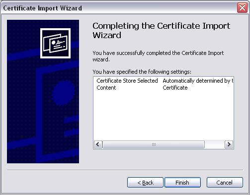
275 (8) Click Finish. 275
 Launch a new IE7")


276 (9) Click Yes. (10) Click OK. (11) Launch a new IE7 browser. The certificate is now trusted via IE7 according to the key symbol shown at top next to the address field. 276
 Open an IE6 browser, the Security Alert message will be appeared if the certificate is not trusted. Click Yes to proceed. (2) The User Login Page will appear. (3) The user can now login normally.")
277 Certificate setting for Internet Explorer 6 For issues relating to IE6 certificate error, the following information provides the step to take when the certificate publisher is not trusted by IE6. (1) Open an IE6 browser, the Security Alert message will be appeared if the certificate is not trusted. Click Yes to proceed. (2) The User Login Page will appear. (3) The user can now login normally. 277


278 Appendix B. Network Configuration on PC & User Login Network Configuration on PC After WHG CONTROLLER is installed, the following configurations must be set up on the PC: Internet Connection Setup and TCP/IP Network Setup. Internet Connection Setup Windows 9x/2000 1) Choose Start >> Control Panel >> Internet Options. 2) Choose the Connections tab, and then click Setup. 278
, and then click Next.")
 DO NOT choose any option in the following LAN window for Internet")
279 3) Choose I want to set up my Internet connection manually, or I want to connect through a local Area network (LAN), and then click Next. 4) Choose I connect through a local area network (LAN) and then click Next. 5) DO NOT choose any option in the following LAN window for Internet configuration, and just click Next. 279
 Finally, click Finish to exit")


280 6) Choose No and then click Next. 7) Finally, click Finish to exit the Internet Connection Wizard. Now, the set up is completed. Windows XP 1) Choose Start >> Control Panel >> Internet Option. 280


281 2) Choose the Connections tab, and then click Setup. 3) When the Welcome to the New Connection Wizard window appears, click Next. 4) Choose Connect to the Internet and then click Next. 281

")

282 5) Choose Set up my connection manually and then click Next. 6) Choose Connect using a broadband connection that is always on and then click Next. 7) Finally, click Finish to exit the Connection Wizard. Now, the setup is completed. 282

 Choose Start >> Control")
283 TCP/IP Network Setup If the operating system of the PC in use is Windows 95/98/ME/2000/XP, keep the default settings without any changes to directly start/restart the system. With the factory default settings, during the process of starting the system, WHG CONTROLLER with DHCP function will automatically assign an appropriate IP address and related information for each PC. If the Windows operating system is not a server version, the default settings of the TCP/IP will regard the PC as a DHCP client, and this function is called Obtain an IP address automatically. If checking the TCP/IP setup or using the static IP in the LAN1/LAN2 or LAN3/LAN4 section is desired, please follow these steps: Check the TCP/IP Setup of Window 9x/ME 1) Choose Start >> Control Panel >> Network. 2) Click on the Configuration tab and select TCP/IP >> AMD PCNET Family Ethernet Adapter (PCI-ISA), and then click Properties. Now, you can choose to use DHCP or a specific IP address. 283


284 3) Using DHCP: If you want to use DHCP, click on the IP Address tab and choose Obtain an IP address automatically, and then click OK. This is also the default setting of Windows. Then, reboot the PC to make sure an IP address is obtained from WHG CONTROLLER. 4) Using Specific IP Address: If you want to use a specific IP address, acquire the following information from the network administrator: the IP Address, Subnet Mask and DNS Server address provided by your ISP and the Gateway address of WHG CONTROLLER. If your PC has been set up completely, please inform the network administrator before proceeding to the following steps. 4.1) Click on the IP Address tab and choose Specify an IP address. Enter the IP Address, Subnet Mask and then click OK. 284


285 4.2) Click on the Gateway tab. Enter the gateway address of WHG CONTROLLER in the New gateway field and click Add. Then, click OK. 4.3) Click on DNS Configuration tab. If the DNS Server field is empty, select Enable DNS and enter DNS Server address. Click Add, and then click OK to complete the configuration. Check the TCP/IP Setup of Window ) Select Start >> Control Panel >> Network and Dial-up Connections. 285
 Select Internet Protocol (TCP/IP) and then click Properties.")
 Using DHCP: If you want to use DHCP, choose Obtain an IP address")

286 2) Right click on the Local Area Connection icon and select Properties. 3) Select Internet Protocol (TCP/IP) and then click Properties. Now, you can choose to use DHCP or a specific IP address. 4) Using DHCP: If you want to use DHCP, choose Obtain an IP address automatically, and then click OK. This is also the default setting of Windows. Then, reboot the PC to make sure an IP address is obtained from WHG CONTROLLER. 286

287 5) Using Specific IP Address: If you want to use a specific IP address, acquire the following information from the network administrator: the IP Address, Subnet Mask and DNS Server address provided by your ISP and the Gateway address of WHG CONTROLLER. If your PC has been set up completely, please inform the network administrator before proceeding to the following steps. 5.1) Choose Use the following IP address and enter the IP address, Subnet mask. If the DNS Server field is empty, select Using the following DNS server addresses and enter the DNS Server address. Then, click OK. 5.2) Click Advanced to enter the Advanced TCP/IP Settings window. 5.3) Click on the IP Settings tab and click Add below the Default gateways column and the TCP/IP Gateway Address window will appear. 287


288 5.4) Enter the gateway address of WHG CONTROLLER in the Gateway field, and then click Add. After back to the IP Settings tab, click OK to complete the configuration. Check the TCP/IP Setup of Window XP 1) Select Start >> Control Panel >> Network Connection. 2) Right click on the Local Area Connection icon and select Properties. 3) Click on the General tab and choose Internet Protocol (TCP/IP), and then click Properties. 288


289 Now, you can choose to use DHCP or a specific IP address. 4) Using DHCP: If you want to use DHCP, choose Obtain an IP address automatically and click OK. This is also the default setting of Windows. Then, reboot the PC to make sure an IP address is obtained from WHG CONTROLLER. 5) Using Specific IP Address: If you want to use a specific IP address, acquire the following information from the network administrator: the IP Address, Subnet Mask and DNS Server address provided by your ISP and the Gateway address of WHG CONTROLLER. If your PC has been set up completely, please inform the network administrator before proceeding to the following steps. 5.1) Choose Use the following IP address and enter the IP address, Subnet mask. If the DNS Server field is empty, select Using the following DNS server addresses and enter the DNS Server address. Then, click OK. 5.2) Click Advanced to enter the Advanced TCP/IP Settings window. 289


290 5.3) Click on the IP Settings tab and click Add below the Default gateways column and the TCP/IP Gateway Address window will appear. 5.4) Enter the gateway address of WHG CONTROLLER in the Gateway field, and then click Add. After back to the IP Settings tab, click OK to finish the configuration. 290
291 Appendix C. Policy Priority Global Policy, Service Zone Policy, Authentication Policy and User Policy WHG Controller supports multiple Policies, including one Global Policy and multiple individual Policy which can be assigned and bound to Group. Global Policy is the system s universal policy and applied to all clients, while other individual Policy can be selected and defined to be applied to any Service Zone. On the other hand, Service Zone also has a Default Policy. For some authentication, such as Local, RADIUS and LDP, user can assign to different Group individually. The clients belonging to a Service Zone will be bound by an applied Policy. In addition, a Policy can be applied at a Group basis; a Group of users can be bound by a Policy. So one user may be applied different policy at the same time. Which policy is actually applied to this user? The Policy Priority must be: User Policy >> Authentication Policy >> Service Zone Policy >> Global Policy Now, let us discus different user policy type: o For Local, RADIUS and LDAP, if these users are assigned to different Group individually, these users can be assigned to their Group. For example, a Local user, user01, is assigned to Group1 and the Local Authentication is assigned to Group2. If Group1 in Service Zone1 can be applied Policy1. Then user01 login to Service Zone1 will get Policy1. This is a common case for users that can assign Group individually. o For Local, RADIUS and LDAP, if these users do not assigned any Group individually, so they are same as other authentication server users that they can not assign to Group individually. For example, a POP3 user, pop01, the POP3 Authentication is assigned to Group1. If Group1 in Service Zone1 can be applied Policy1. Then pop01 login to Service Zone1 will get Policy1. This is another common case for users that can assign Group by authentication server. o If Authentication server also do not assign to a Group, then the user will applied the Service Zone Default Policy. For example, a Local user, user01, is assigned to Group None and the Local Authentication is also assigned to Group None. If the Default Policy of Service Zone1 is applied Policy1. Then user01 login to Service Zone1 will get Policy1. o If the Default Service Zone Policy is None. Authentication server does not assign to a Group and user Group is None too. For example, a Local user, user01, is assigned to Group None and the Local Authentication is also assigned to Group None. If the Default Policy of Service Zone1 is None. Then user01 login to Service Zone1 will apply the Global Policy. So, the Global Policy has the lowest policy priority; on the other hand, the User Policy will be the highest one. 291
292 Appendix D. RADIUS Accounting This section is trying to organize the basic configuration with RADIUS server to work with VSA. The aim is trying to control the maximum usage (upload; download or upload + download traffic) of clients in each session. This VSA will send from RADIUS server to gateway along with an Access-Accept packet. In other words, when the external RADIUS server accepts the request, it will not only reply with an Access-Accept and it will also carry a maximum value in bytes that each user is allowed to transfer. This value may be the maximum upload traffic; download traffic or the summation of each user s download plus upload traffic in bytes. Gateway will check this value every minute, if the user is reached this value, gateway will stop the session of this user and send a Stop to RADIUS server. 1. Description This Attribute is available to allow vendors to support their own extended Attributes not suitable for general usage. It MUST not affect the operation of the RADIUS protocol. The standard Attribute Type of VSA is 26. Also we need to know the Vendor ID, in this example; the Vendor ID of LevelOne is There must have other attribute to define the amount of traffic with Attribute Number and Attribute Value : Attribute Name Attribute Number Attribute Value LevelOne-Byte-Amount 10 To be defined by administrator for different user group LevelOne-MaxByteIn 11 To be defined by administrator for different user group LevelOne-MaxByteOut 12 To be defined by administrator for different user group LevelOne-Byte-Amount-4GB 20 To be defined by administrator for different user group LevelOne-MaxByteIn-4GB 21 To be defined by administrator for different user group LevelOne-MaxByteOut-4GB 22 To be defined by administrator for different user group If the amount of traffic is larger than 4 GB, then the attribute of XXXX-4GB is for the carry. For example, if the amount is 5 GB, you must set LevelOne-Byte-Amount = and LevelOne-Byte-Amount-4GB = 1. On the other hand, if administrator fills in all attributes, it means that if any condition is reached, the user will be kicked out from system. For example, if administrator set LevelOne-Byte-Amount = ; LevelOne- MaxByteIn = and LevelOne- MaxByteOut = It means that whatever the downlink or uplink or total traffic exceeded the limit, the user will be kicked out from system. 292

293 2. VSA configuration in RADIUS server (IAS Server) This section will guide you through a VSA configuration in your external RADIUS server. Before getting start, please access your external RADIUS server s desktop directly or remotely from other PC. Step 1 Assume there are already have users in RADIUS Server Assume there are already have Groups and assigned users to belong these Groups in RADIUS Server Assume there are already have Policies and assigned Groups to belong these Policies in RADIUS Server Step 2 Run Internet Authentication Server Open Remote Access Policies Select a Policy Right click and scroll down to its properties page 293

294 Step 3 Edit Profile Select the Advanced Tag Add a new attribute Add a new Vendor-specific attribute Step 4 Add a new attribute under Vendor-specific Set Vendor Code = Set it conforms to the RADIUS RFC Configure Attribute Set Vendor-assigned attribute number = 10 Set Attribute format = Hexadecimal Set Attribute Value =


295 Step 5 Confirm the Vendor-specific Attribute has been added success Step 6 Follow the same steps to create other Vendor-specific Attribute as you need. 295

296 3. VSA configuration in RADIUS server (FreeRADIUS) This section will guide you through a VSA configuration using the operating system Fedora FreeRADIUS version Before getting start, open the shell of RADIUS server, for example, use Putty to access the Linux Host: Step 1 Assume there are already have users in RADIUS Server Assume there are already have Groups and assigned users to belong these Groups in RADIUS Server Step 2 Login the Linux Host of the RADIUS server. Step 3 Create a file dictionary.levelone under the freeradius folder. Step 4 Edit and save the content of the file dictionary.levelone as the following: 296


297 Administrator also can add other attributes as the table stated in Section 2 with same format. Step 5 Edit the file dictionary under the folder freeradius. Step 6 Include dictionary.levelone in the dictionary of RADIUS server. Insert it in an incremental position that easy to find it again. Step 7 Open the radius database. 297

298 Step 8 Insert VSA into RADIUS respond. In this example, the maximum download and upload in bytes for group03 users is 1MBytes. Step 9 Restart RADIUS to get your settings activated. 298
299 Appendix E. VLAN Port Location Mapping and PMS Middleware This section introduces the Port Location Mapping feature. This feature is designed for creating multiple VLAN divisions (as if they were separate LAN ports) under a Service Zone and mapping these VLANs to different locations individually. This feature can be utilized to provide separate VLAN to separate clients in MTU/MDU deployments where a VLAN switch is deployed under the gateway to provide VLAN connection to individual rooms. The Port Location Mapping feature is also commonly used in hospitality venues to manage the internet service for their guest rooms and public areas. In addition it can operate in conjunction with third party hospitality applications and has been tested with the Net Retriever middleware which provides seamless integration between the gateway and the popular High Speed Internet Access (HSIA) hardware and Front Office System (FOS) software. Each Port Location Mapping entry can be configured to provide charged (single or multiple user), free or blocked internet service at the location corresponding to the entry s VLAN Tag. Please note that for charged service to work, it is required that least one or more On-demand Billing Plans are created, allowing the user to choose a desired plan to pay for their internet access. Note: For more detail of On-demand Billing Plan configuration, please refer to the section of On-demand Users. 1. Enabling Port Location Mapping The Port Location Mapping feature allows each Service Zone to own multiple VLANs (as if each VLAN is a port) in order to identify where the clients are coming from. Before the configuration of the PMS Middleware or adding VLANs to a Service Zone, the Port Mapping feature must be enabled first; go to: System >>Port Location Mapping. 299
 to a VLAN port of VLAN switch or a DSLAM device. Each Room is mapped to a VLAN Tag.")
300 2. Port Location Mapping Configure Port Location Mapping; go to: System >>Port Location Mapping>> Configure. Administrator could use Port Location Mapping feature to map a location (such as a hotel room) to a VLAN port of VLAN switch or a DSLAM device. Each Room is mapped to a VLAN Tag. And each Room can be assign to different Service Zone to get different policy. Furthermore, according to your application, you can configure the different rooms to different Port Type: Single User, Multiple User, Free or Block. Free, this port type means the user can access internet in this room without any charge. If you do not want to provide any internet access right in the rooms, you may change the Port type of the rooms to Block. If the user opens a browser and tries to access internet, it will pop up a Blocking message to notify the user. Single User port type is used mainly for hospitality application to charge a single user. If the user opens a browser and tries to access internet, a page with disclaimer and billing plan options will be displayed. User can select the desired plan and click confirm button to purchase an account. The account cost will be sent to the PMS and added to the hotel bill via the configured middleware. The room with this port type only allows one user at most to access the network within the room. 300
301 Multiple User is the port type used for rooms with many users for example dormitory applications. If the user opens a browser and tries to access internet, a user login page without billing plan options will be displayed. The user needs to buy accounts from the front dorm office in order to login. The room with this port type allows more than one user to access the network within the room. Now, let us begin to configure the Port Mapping. There are three main groups of operations that can be performed in this configuration page: Create Batch, Change All Port Type and Create One. You can create the Room Mapping by batch processing if you wish to create a contiguous VLAN Tag and Room number. Port Location Mapping Setup Create Batch From: Set the Physical LAN port on the gateway to provide Port Location Mapping Service. Port Type: The default state of the rooms, it may be: Free, Block, Single User, Multiple User. Service Zone: The service zone profile used to provide internet service to the corresponding room or location. VLAN ID Start: The starting VLAN ID. Number of VLAN: The total number of VLAN. Start Room Number / Location ID: The start room number. Room NUM / Location ID Prefix: The prefix of room number. Room NUM / Location ID Postfix: The postfix of room number. After you have created the VLAN Tag and Room number mapping, you can change the Port Type for all entries in a particular Service Zone. Port Location Mapping Setup Change All Port Type Port Type: The Port Type that will be applied to all of the mapping entries, it may be: Free, Block, Single User, Multiple User. Service Zone: Select to change the Port Type of which Service Zone. If you want to create the Room Mapping with noncontiguous VLAN Tag and Room number, then you can create them individually. 301

302 Port Location Mapping Setup Create One From: Set the Physical LAN port on the gateway to provide Port Location Mapping Service. Port Type: The default state of the rooms, it may be: Free, Block, Single User, Multiple User. Service Zone: The service zone profile used to provide internet service to this room. VLAN ID: The VLAN ID to be designated to this room. Room Number / Location ID: The room number mapping to this VLAN ID. Room Description / Location Name: Additional reference or remark information of this room. The VLAN Tags configured in Port Location Mapping must not conflict with any of the VLAN Tags that has been assigned to each Service Zone. When you have finished creating Port Location Mapping profiles, go back to the Port Location Mapping page, the Port Location Mapping List displays all the profile entries with information such as its VLAN ID, Room Num/Location ID, Port Type and Service Zone. 3. PMS Middleware (For hospitality application) Now, let us begin to configure the PMS Middleware (Net Retriever) connection: Configure Middleware Connection Setup; go to: Users >>Middleware >>Connection Setup. Middleware Configuration Event Log: Record all the Middleware Event Log. Middleware Connection Setup 302
 to test the authenticity of the link.")
303 Connection Setup: Enter the Secret, Interface Port, MI ID, AC ID, and Link Test Interval for Middleware connection. Secret: The secret key between Guest Service Device and PMS Middleware for challenge and response (MD5 Hash) to test the authenticity of the link. It should contain one or more lowercase letters, uppercase letters, numbers and symbols. It also should be between 8 ~ 16 characters. Interface Port: The port used by Net Retriever, the default is MI ID: The ID of the Middleware. AC ID: The ID of the Access WHG Controller (the gateway). Link Test Interval: The time interval for the gateway to perform Link Test, the default is 300 seconds. Now, the PMS Middleware connection is finished in the Access WHG Controller side. In the PMS Middleware (Net Retriever) side, it has to know the IP address of Access WHG Controller, Secret Key, AC ID and MD ID configured in Middleware Connection Setup in order for the two interfaces to communicate to each other. 4. Check or modify the Port Location Mapping profile If you want to check the room mapping information or you want to change any setting of the room mapping. To configure Port Location Mapping List, go to: System >> Port Location Mapping. The Port Location Mapping List displays all the profile entries with information such as its VLAN ID, Room Num/Location ID, Port Type and Service Zone. Clicking the Delete link can erase an individual Port Location Mapping profile. Clicking Delete All button will erase all of the Port Location Mapping profiles. 303
304 The Search field allows administrator to search for mapping entries according to VLAN ID, Room Num/Location ID or Service Zone. Click the VLAN ID link to enter the Port Mapping Profile page for that entry. You can change the Port Type or Service Zone of this room. You also can check the present user account information. 5. Accessing Internet from a room After planning your VLAN network and completing all the Port Location Mapping settings, you should verify whether the configurations are working properly. According to the Port Type set, when a user tries to access the internet from a VLAN mapped room, the pages or messages displayed are as follows: When a user tries to access internet from a Single User room, the browser will show the Login page with a list of available plans and service agreement. The Service Agreement body can be configured at the applied Service Zone s Custom Pages settings. User may chose a billing plan, click the Confirm button and the system 304


305 will display the generated account name and password. If you already have a user account, you can click the here link to login with the user account that you possess. When a user tries to access internet from a Multiple User room, the browser will show the Login page without billing plans options to select. The User will need to buy accounts from the front desk or reception to login. 305


306 When a user tries to access internet from a Free room, the browser will show service agreement page, simply by clicking CONFIRM and the user can access the internet. The Service Agreement body can be configured at the applied Service Zone s Custom Pages settings. When a user tries to access internet from a Block room, the browser will show service unavailable page. 6. View the Event Login After the user select a billing plan and buy it to access Internet. You can check the Middleware Event Log for information relating to users that have purchased accounts from VLAN mapped rooms. To View Net Retriever Event Log, go to: Users >>Middleware >>Event Log. 306
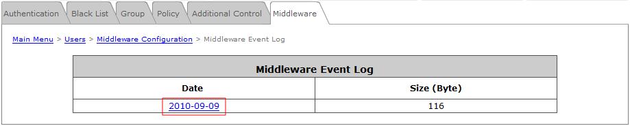
307 P/N: VWHG
WHG311 V1.03. Secure WLAN Controller
 WHG311 V1.03 Secure WLAN Controller Copyright Notice This document is protected by USA copyright laws and other laws and is the property of 4IPNET, INC. You may not copy, reproduce, distribute, publish,
WHG405 V2.10. Secure WLAN Controller
 WHG405 V2.10 Secure WLAN Controller Copyright Notice This document is protected by USA copyright laws and other laws and is the property of 4IPNET, INC. You may not copy, reproduce, distribute, publish,
WHG425 V3.20. Secure WLAN Controller
 WHG425 V3.20 Secure WLAN Controller Copyright Notice This document is protected by USA copyright laws and other laws and is the property of 4IPNET, INC. You may not copy, reproduce, distribute, publish,
WHG325 V3.30. Secure WLAN Controller
 WHG325 V3.30 Secure WLAN Controller Copyright Notice This document is protected by USA copyright laws and other laws and is the property of 4IPNET, INC. You may not copy, reproduce, distribute, publish,
WHG711 V3.20. Secure WLAN Controller
 WHG711 V3.20 Secure WLAN Controller Copyright Notice This document is protected by USA copyright laws and other laws and is the property of 4IPNET, INC. You may not copy, reproduce, distribute, publish,
WHG201 V1.00. Secure WLAN Controller
 WHG201 V1.00 Secure WLAN Controller Copyright Notice This document is protected by USA copyright laws and other laws and is the property of 4IPNET, INC. You may not copy, reproduce, distribute, publish,
User s Manual AMG-2102 Gigabit Access and AP Management Gateway Pro. AMG-2102 Gigabit Access and AP Management Gateway Pro User s Manual V1.
 AMG-2102 Gigabit Access and AP Management Gateway Pro V1.0 Table of Contents 1. Before You Start... 1 1.1 Preface... 1 1.2 Document Conventions... 1 1.3 Package Checklist... 2 2. System Overview and Getting
AMG-2001 Access and AP Management Gateway
 AMG-2001 Access and AP Management Gateway V1.0 Table of Contents 1. Before You Start...1 1.1 Preface...1 1.2 Document Conventions...1 1.3 Package Checklist...2 2. System Overview and Getting Start...3
4Gon Tel: +44 (0) Fax: +44 (0)
 Fax: +44 (0)") WHG401 V1. 21 Copyright N otic e This document is protected by USA copyright laws and other laws and is the property of 4 I P N E T, I N C. Y ou may not copy, reproduce, distribute, publish, display, perform,
WHG401 V1. 21 Copyright N otic e This document is protected by USA copyright laws and other laws and is the property of 4 I P N E T, I N C. Y ou may not copy, reproduce, distribute, publish, display, perform,
WHG713. Secure WLAN Controller
 WHG713 Secure WLAN Controller Copyright Notice This document is protected by USA copyright laws and other laws. Besides, the document is the property of 4IPNET, INC. You may not copy, reproduce, distribute,
LevelOne. Quick Installation Guide. WHG series Secure WLAN Controller. Introduction. Getting Started. Hardware Installation
 Introduction LevelOne WHG series Secure WLAN Controller LevelOne Secure WLAN Controller is the most advanced yet simple deployment and cost-effective wireless solution; it is an ideal security solution
EWS5207. Secure WLAN Controller
 EWS5207 Secure WLAN Controller Copyright Notice This document is protected by USA copyright laws and other laws and is the property of Edgecore Networks Corporation. You may not copy, reproduce, distribute,
4ipnet WHG311 Secure WLAN Controller
 Product Name: Manufacturer: 4ipnet Model Number: WHG311 Please Note: The 4ipnet WHG311 has been discontinued. For an alternative, we recommend the 4ipnet WHG321. The with built-in 3,000 local accounts,
LevelOne. AMG-2000 AP Management Gateway. User Manual. v
 LevelOne AP Management Gateway User Manual v2.0-0705 Table of Contents Chapter 1. Before You Start... 3 1.1 Preface... 3 1.2 Document Convention... 3 Chapter 2. System Overview... 4 2.1 Introduction of...
CE APPROVED.4 INTRODUCTION.5 PACKAGE CONTENTS. 6 PRE - INSTALLATION CHECKLIST. 6 SYSTEM REQUIREMENTS. 6 FEATURES AND BENEFITS.11 SETUP WIZARD.
 Web Edition Dec. 2002 Contents CE APPROVED...4 INTRODUCTION...5 PACKAGE CONTENTS... 6 PRE - INSTALLATION CHECKLIST... 6 SYSTEM REQUIREMENTS... 6 FEATURES AND BENEFITS... 7 4 - PORT CABLE/XDSL ROUTER...9
WHG711 Wireless LAN Controller
 WHG711 Wireless LAN Controller Wireless INTRODUCTION The WHG711 is an enterprise-grade wireless LAN controller that provides establishments such as hotels, universities, or even complete municipalities
IP806GA/GB Wireless ADSL Router
 IP806GA/GB Wireless ADSL Router 802.11g/802.11b Wireless Access Point ADSL Modem NAT Router 4-Port Switching Hub User's Guide Table of Contents CHAPTER 1 INTRODUCTION... 1 Wireless ADSL Router Features...
CHAPTER 7 ADVANCED ADMINISTRATION PC
 ii Table of Contents CHAPTER 1 INTRODUCTION... 1 Broadband ADSL Router Features... 1 Package Contents... 3 Physical Details... 4 CHAPTER 2 INSTALLATION... 6 Requirements... 6 Procedure... 6 CHAPTER 3 SETUP...
RANGER SERIES. 150Mbps Wireless Green Broadband Router DG-BR4000NG. 150 Mbps V
 RANGER SERIES 150Mbps Wireless Green Broadband Router DG-BR4000NG N 150 Mbps V1.2 2011-12-15 FCC warning: This equipment has been tested and found to comply with the limits for a class B digital device,
Security SSID Selection: Broadcast SSID:
 69 Security SSID Selection: Broadcast SSID: WMM: Encryption: Select the SSID that the security settings will apply to. If Disabled, then the device will not be broadcasting the SSID. Therefore it will
LevelOne FBR User s Manual. 1W, 4L 10/100 Mbps ADSL Router. Ver
 LevelOne FBR-1416 1W, 4L 10/100 Mbps ADSL Router User s Manual Ver 1.00-0510 Table of Contents CHAPTER 1 INTRODUCTION... 1 FBR-1416 Features... 1 Package Contents... 3 Physical Details... 3 CHAPTER 2
User s Manual V HSG326 Wireless Hotspot Gateway
 V1.00.00 HSG326 Wireless Hotspot Gateway Copyright The contents of this publication may not be reproduced in any part or as a whole, stored, transcribed in an information retrieval system, translated into
Light Mesh AP. User s Guide. 2009/2/20 v1.0 draft
 Light Mesh AP User s Guide 2009/2/20 v1.0 draft i FCC Certifications This equipment has been tested and found to comply with the limits for a Class B digital device, pursuant to Part 15 of the FCC Rules.
1. Package contents. 2. Connecting ADSL modem and wireless router
 1. Package contents WL-500W wireless router x 1 Power adapter x 1 Utility CD x 1 RJ45 cable x 1 Quick Start Guide x 1 2. Connecting ADSL modem and wireless router 1) Cable connection Wall power outlet
Wireless 11n Smart Repeater AP (1T1R)
") (1T1R) 2014 Table of Contents 1. Introduction...3 1.1 Package contents... 3 1.2 Product Features... 3 1.3 Front Panel Description... 4 1.4 Rear Panel Description... 5 2. Installation...6 2.1 Hardware Installation...
(1T1R) 2014 Table of Contents 1. Introduction...3 1.1 Package contents... 3 1.2 Product Features... 3 1.3 Front Panel Description... 4 1.4 Rear Panel Description... 5 2. Installation...6 2.1 Hardware Installation...
IP806GA/GB Wireless ADSL Router
 IP806GA/GB Wireless ADSL Router 802.11g/802.11b Wireless Access Point ADSL Modem NAT Router 4-Port Switching Hub User's Guide DECLARATION OF CON FORMITY This device complies with Part 15 of the FCC Rules.
LANPRO LP-NC1 User s Manual
 Version 1.00 Table of Contents Chapter 1. Before You Start...1 1.1 Preface...1 1.2 Document Convention...1 Chapter 2. System Overview...2 2.1 Introduction of...2 2.2 System Concept...2 2.3 Specification...3
AC1200M/MS. User Manual
 AC1200M/MS User Manual Table of Contents User Manual... 1 1 Preface... 1 2 LED Indicators and Connectors... 1 2.1 LED Indicators... 1 2.2 Hardware Installation... 2 3 Voice Prompt (AC1200MS)... 2 4 User
User Manual. AC ac Wireless Access Point/Router. Model WAC124. NETGEAR, Inc.
 AC2000 802.11ac Wireless Access Point/Router Model WAC124 December 2018 202-11885-02 NETGEAR, Inc. 350 E. Plumeria Drive San Jose, CA 95134, USA AC2000 802.11ac Support Thank you for purchasing this NETGEAR
ZyWALL 70. Internet Security Appliance. Quick Start Guide Version 3.62 December 2003
 ZyWALL 70 Internet Security Appliance Quick Start Guide Version 3.62 December 2003 Introducing the ZyWALL The ZyWALL 70 is the ideal secure gateway for all data passing between the Internet and the LAN.
User Manual Gemtek WiMAX Modem
 User Manual Gemtek WiMAX Modem WIXS-177 CONTENTS Chapter 1 Overview...1-1 1.1. Indoor CPE... 1-1 1.2. Outdoor CPE... 1-2 Chapter 2 WEB-GUI...2-3 2.1. System Configuration Login... 2-3 2.2. System Logout...
ZyWALL 10W. Internet Security Gateway. Quick Start Guide Version 3.62 December 2003
 Internet Security Gateway Quick Start Guide Version 3.62 December 2003 Introducing the ZyWALL The is the ideal secure gateway for all data passing between the Internet and the LAN. By integrating NAT,
The VWRT510&WRT500 High Speed Router User s Guide
 The VWRT510&WRT500 High Speed Router User s Guide The page 1 of 53 Table of Contents 1 Preface... 4 2 LED Indicators and Connectors... 5 2.1 LED Indicators... 6 2.2 Hardware Installation... 7 3 Voice Prompt...
Peplink Balance Multi-WAN Routers
 Peplink Balance Multi-WAN Routers Model 20/30/210/310/380/390/580/710/1350 User Manual Firmware 5.1 September 10 Copyright & Trademarks Specifications are subject to change without prior notice. Copyright
802.11a g Dual Band Wireless Access Point. User s Manual
 802.11a+802.11g Dual Band Wireless Access Point User s Manual 0 Chapter 1 Introduction 1.1 Feature Fully interoperable with IEEE 802.11b compliant products. High-Speed data transfer rate up to 11Mbps.
Contents Introduction to the Product Configuration CPE built-in Web Server Access CPE Setup on the web page Trouble Shooting Operating Information
 Contents Introduction to the Product Functional Features LED Information Rear Side Information Configuration Network Configuration Package Configuration PC Configuration(Windows XP) How to check your IP
LevelOne. User Manual. WAP Mbps PoE Wireless AP V3.0.0
 LevelOne WAP-0005 108Mbps PoE Wireless AP User Manual V3.0.0 i TABLE OF CONTENTS CHAPTER 1 INTRODUCTION... 1 FIGURE 1: WIRELESS ACCESS POINT... 1 FEATURES OF YOUR WIRELESS ACCESS POINT... 1 Security Features...
Package Contents. Preface. Front Panel. Rear Panel
 Quick Installation Guide V2. 0 0 Copyright N otic e This document is protected by USA copyright laws and other laws and is the property of 4 I P N E T, I N C. Y ou may not copy, reproduce, distribute,
FWRIII-2105 SERIES. 4 ports 10/100Mbps RJ-45; built-in IEEE802.11n WiFi and 1 port 100Mbps SFP slot uplink Residential Gateway. Residential Gateway
 FWRIII-2105 SERIES 4 ports 10/100Mbps RJ-45; built-in IEEE802.11n WiFi and 1 port 100Mbps SFP slot uplink Residential Gateway 4 ports 10/100Mbps RJ-45; built-in IEEE802.11n WiFi and 1 port 100Mbps SFP
Wireless Network Video Recorder
 LD2R/LD2R500 Wireless Network Video Recorder User Guide Version 1.0 PREFACE Thank you for purchasing the Wireless Network Video Recorder, an IP based device that installed on your network, which can be
LevelOne WBR User s Manual. 11g Wireless ADSL VPN Router. Ver
 LevelOne WBR-3407 11g Wireless ADSL VPN Router User s Manual Ver 1.00-0510 Table of Contents CHAPTER 1 INTRODUCTION... 1 Wireless ADSL Router Features... 1 Package Contents... 5 Physical Details... 6 CHAPTER
WISNETWORKS. WisOS 11ac V /3/21. Software version WisOS 11ac
 WISNETWORKS User Manual V1.1 2016/3/21 Software version 1.0.0021 Table of contents 1. Setup& WMI... 3 1.1 Hardware Setup... 3 1.2 Web Management Interface... 3 2. Status... 4 2.1 Overview... 4 2.1.1 System...
WRT300N-DD User Manual
 WRT300N-DD User Manual Contents Features... 3 Configuring the Router... 3 1 Operation Mode... 8 2 Internet Settings... 8 2.1 WAN... 9 2.2 LAN... 13 2.3 DHCP clients... 15 2.4 Advanced Routing... 15 2.5
Wireless Access Point
 802.11g / 802.11b / WPA Wireless Access Point User's Guide TABLE OF CONTENTS CHAPTER 1 INTRODUCTION... 1 Features of your Wireless Access Point... 1 Package Contents... 4 Physical Details... 4 CHAPTER
HES-3109 SERIES 9 PORTS 10/100/1000BASE-T MANAGEMENT ETHERNET SWITCH
 HES-3109 SERIES 9 PORTS 10/100/1000BASE-T MANAGEMENT ETHERNET SWITCH 8 PORTS 10/100/1000BASE-T MANAGEMENT ETHERNET SWITCH WITH 1 PORT 1000BASE-X UPLINK OR 1 PORT 100/1000BASE-X UPLINK 8 PORTS 10/100/1000BASE-T
WiFi-Repeater User Manual. Quick Installation Guide(Q.I.G.) REV.1.2
 REV.1.2") WiFi-Repeater User Manual Quick Installation Guide(Q.I.G.) REV.1.2 Introduction: The WiFi Repeater is a combined wired/wireless network connection device designed specifically for small business, office,
WiFi-Repeater User Manual Quick Installation Guide(Q.I.G.) REV.1.2 Introduction: The WiFi Repeater is a combined wired/wireless network connection device designed specifically for small business, office,
AirCruiser G Wireless Router GN-BR01G
 AirCruiser G Wireless Router GN-BR01G User s Guide i Contents Chapter 1 Introduction... 1 Overview...1 Features...1 Package Contents...2 AirCruiser G Wireless Router Rear Panel...2 AirCruiser G Wireless
User Manual. VDSL2 Router with 11n WiFi. Model:DV2211
 Model:DV2211 User Manual VDSL2 Router with 11n WiFi Model:DV2211 V33 User Manual 1 Model:DV2211 TABLE OF CONTENTS... 1 Device Installation... 4 Power on Router... 4 Factory Reset Button... 5 Network Connections...
Broadband Router DC-202. User's Guide
 Broadband Router DC-202 User's Guide Table of Contents CHAPTER 1 INTRODUCTION... 1 Broadband Router Features... 1 Package Contents... 3 Physical Details...3 CHAPTER 2 INSTALLATION... 5 Requirements...
300M Wireless-N Broadband Router User Manual
 300M Wireless-N Broadband Router Model No.: ib-wrb314n User Manual Ver.: 1.0.0 Contents...Error! Bookmark not defined. Chapter 1 Product Overview... 3 Package Contents 3 Conventions....4 Panel Overview...
802.11N Wireless Broadband Router
 802.11N Wireless Broadband Router Pre-N Wireless Access Point Broadband Internet Access WPS 4-Port Switching Hub User's Guide Table of Contents CHAPTER 1 INTRODUCTION... 1 Wireless Router Features... 1
COPYRIGHT. Linux Open Source Code Certain Edimax products include software codes developed by third parties, which are
 COPYRIGHT Copyright Edimax Technology Co., Ltd. all rights reserved. No part of this publication may be reproduced, transmitted, transcribed, stored in a retrieval system, or translated into any language
User Guide TL-R470T+/TL-R480T REV9.0.2
 User Guide TL-R470T+/TL-R480T+ 1910012468 REV9.0.2 September 2018 CONTENTS About This Guide Intended Readers... 1 Conventions... 1 More Information... 1 Accessing the Router Overview... 3 Web Interface
TD-8616 ADSL2/2+ Ethernet Modem
 TD-8616 ADSL2/2+ Ethernet Modem Rev: 1.0.1 1910010001 COPYRIGHT & TRADEMARKS Specifications are subject to change without notice. is a registered trademark of TP-LINK TECHNOLOGIES CO., LTD. Other brands
11g Wireless Broadband Router
 LevelOne WBR-3408 User Manual 11g Wireless Broadband Router (Roteador banda-larga sem fio- Wireless G) Ver. 3.000 Safety FCC WARNING This equipment may generate or use radio frequency energy. Changes or
NBG-416N. Wireless N-lite Home Router. Default Login Details. IMPORTANT! READ CAREFULLY BEFORE USE.
 NBG-416N Wireless N-lite Home Router IMPORTANT! Default Login Details LAN IP https://192.168.1.1 Address User Name admin Password 1234 READ CAREFULLY BEFORE USE. KEEP THIS GUIDE FOR FUTURE REFERENCE. IMPORTANT!
Broadband Router User s Manual. Broadband Router User s Manual
 Broadband Router User s Manual Table of Contents 1 Introduction... 1 1.1 Features... 1 1.2 Package Contents... 2 1.3 LEDs & Connectors of Broadband Router... 2 1.4 System Requirements... 2 1.5 Installation
Content 1 OVERVIEW HARDWARE DESCRIPTION HARDWARE INSTALLATION PC CONFIGURATION GUIDE... 5 WEB-BASED MANAGEMENT GUIDE...
 Content 1 OVERVIEW...1 1.1FEATURES...1 1.2 PACKETCONTENTS...3 1.3 SYSTEM REQUIREMENTS... 1.4 FACTORY DEFAULTS...4 1.5 WARNINGS AND CAUTIONS...4 2 HARDWARE DESCRIPTION... 6 3 HARDWARE INSTALLATION...8 4
G-4200 SMB PAC with built-in AAA
 G-4200 SMB PAC with built-in AAA 10 Mar. 2008 Browan, Inc. Version 1.1 Page 1 Production overview The G-4200 is a cost-effective platform designed for small to medium sized public access venues. AT-A-GLANCE:
FCC CAUTION SETTING... 9
 1 FCC CAUTION... 3 1 INTRODUCTION... 5 1.1 LED INDICATORS... 6 1.2 PRODUCT APPEARANCE... 7 2 INSTALLATION DIAGRAM... 7 3 SETTING... 9 3.1 USING LAPTOP... 9 3.2 USING IPHONE/IPAD... 13 3.3 USING ANDROID
LevelOne GES GE with 1 Combo SFP Web Smart Switch User Manual
 LevelOne GES-0852 8 GE with 1 Combo SFP Web Smart Switch User Manual Version 1.0-1109 1 FCC Certifications This Equipment has been tested and found to comply with the limits for a Class A digital device,
CTX 1000 VoIP Accelerator User Guide
 CTX 1000 Version 2.0 March 2007 Part #: 721-000410-00 Rev. A CTX 1000 VoIP Accelerator User Guide CTX 1000 VoIP Accelerator User Guide Version 2.0 Copyright 2007 by Converged Access Inc. Littleton, MA
UTM Content Security Gateway CS-2001
 UTM Content Security Gateway CS-2001 Quick Installation Guide Table of Contents 1. Package Contents... 3 2. Setup the UTM Content Security Gateway... 4 3. Hardware Installation... 5 4. Basic System Configuration...
BW1330. High Performance Hotspot Access Point
 BW1330 High Performance Hotspot Access Point 9 July 2008 Overview Hardware Introduction Product Specification Product Features Application Overview Overview The BW1330 Hotspot Access Point is a high-performance
RX3041. User's Manual
 RX3041 User's Manual Table of Contents 1 Introduction... 2 1.1 Features and Benefits... 3 1.2 Package Contents... 3 1.3 Finding Your Way Around... 4 1.4 System Requirements... 6 1.5 Installation Instruction...
Barracuda Link Balancer
 Barracuda Networks Technical Documentation Barracuda Link Balancer Administrator s Guide Version 2.3 RECLAIM YOUR NETWORK Copyright Notice Copyright 2004-2011, Barracuda Networks www.barracuda.com v2.3-111215-01-1215
EAP200 V2.00. Enterprise Access Point
 EAP200 V2.00 Enterprise Access Point Copyright & Disclaimer Copyright The contents of this publication may not be reproduced in any part or as a whole, stored, transcribed in an information retrieval system,
Quick Start Guide for Standalone EAP
 Quick Start Guide for Standalone EAP CHAPTERS 1. Determine the Management Method 2. Build the Network Topology 3. Log In to the EAP 4. Edit the SSID 5. Configure and Manage the EAP This guide applies to:
Broadband High-Speed DSL Modem User Manual
 Broadband High-Speed DSL Modem User Manual Model DM200 September 2017 202-11621-03 350 E. Plumeria Drive San Jose, CA 95134 USA Support Thank you for purchasing this NETGEAR product. You can visit www.netgear.com/support
Peplink SD Switch User Manual. Published on October 25th, 2018
 Peplink SD Switch User Manual Published on October 25th, 2018 1 Table of Contents Switch Layout 4 Specifications 5 Hardware Overview 6 Quick Start Functions 7 Reset Switch 7 Connect Ethernet 7 Connect
N150 WiFi DSL Modem Router Essentials Edition. N300 WiFi DSL Modem Router Essentials Edition
 N150 WiFi DSL Modem Router Essentials Edition Model D500 N300 WiFi DSL Modem Router Essentials Edition Model D1500 User Manual May 2018 202-11390-02 350 East Plumeria Drive San Jose, CA 95134 USA Support
AIRNET 54Mb b/g High Power USB Adapter. User s Manual
 AIRNET 54Mb 802.11b/g High Power USB Adapter User s Manual FCC Certifications Federal Communication Commission Interference Statement This equipment has been tested and found to comply with the limits
User Guide. DOCSIS 3.0 High Speed Cable Modem TC7650 REV
 User Guide DOCSIS 3.0 High Speed Cable Modem TC7650 REV1.1.0 1910011895 Contents About This Guide..................................................... 1 Chapter 1. Get to Know Your Modem................................
Grandstream Networks, Inc.
 Grandstream Networks, Inc. GWN7000 Enterprise Router & Access Point Manager COPYRIGHT 2016 Grandstream Networks, Inc. http://www.grandstream.com All rights reserved. Information in this document is subject
TL-R860 Cable/DSL Router
 TL-R860 Cable/DSL Router Rev: 1.1.0 19100100342 COPYRIGHT & TRADEMARKS Specifications are subject to change without notice. is a registered trademark of TP-LINK TECHNOLOGIES CO., LTD. Other brands and
Broadband Router DC 202
 Broadband Router DC 202 Full Manual Table of Contents DC-202 xdsl/cable Broadband router REQUIREMENTS...4 INTRODUCTION...4 DC-202 Features...4 Internet Access Features...4 Advanced Internet Functions...5
WNAP 3G MOBILE ROUTER. Quick Installation Guide
 WNAP 3G MOBILE ROUTER Quick Installation Guide To avoid users without access right through your WNAP 3G Mobile Router, it is suggested to change WLAN SSID and password and admin password for web configuration
Quick Installation Guide of Acer WLAN 11b Broadband Router
 Preparation 1 At lease one PC with IEEE802.11b WLAN client installed. 2 One straight-through Category 5 Ethernet cable, used to link WAN interface to xdsl or CM for Internet connection. 3 Acer WLAN 11b
Unified Office Gateway UMG Quick Installation Guide. Version: 1.0
 Unified ice Gateway UMG-2000 Quick Installation Guide Version: 1.0 Table of Contents 1. Package Contents... 3 2. Overview... 4 3. Hardware Installation... 6 3.1 Unpack the UMG-2000... 6 3.2 Choosing a
HW550-3G. 3G Mobile Broadband plus 4-Port Wireless-N Router
 HW550-3G 3G Mobile Broadband plus 4-Port Wireless-N Router Table of Contents About the Product...4 Features...5 Requirements...6 Package Content...7 Device Design...8 Getting Started...11 Plan Your Network...12
User Manual. Rev:
 Default Login Details Login Address: www.mykasda.com Login Password: Set up by users Default Wi-Fi SSID: Kasda xxxx KW6516 (Printed on product label) Default Wi-Fi Password: 12345678 www.kasdanet.com Rev:
HES-3106-PLUS SERIES
 HES-3106-PLUS SERIES 5 PORTS 10/100/1000BASE-T ETHERNET MANAGED SWITCH WITH 1 PORT 1000BASE-X or 100/1000BASE-X UPLINK User s Guide Version 0.92 Trademarks CTS is a registered trademark of Connection Technology
UTM Content Security Gigabit Gateway CS-950
 UTM Content Security Gigabit Gateway CS-950 Quick Installation Guide Table of Contents 1. Package Contents... 3 2. Hardware Introduction... 4 2.1 Hardware Interface... 4 2.2 Hardware Installation... 6
LevelOne User Manual WBR g Wireless ADSL2+ Router
 LevelOne User Manual WBR-3600 11g Wireless ADSL2+ Router V1.0.1-0809 1 FCC Statement This equipment has been tested and found to comply with the limits for a Class B digital device, pursuant to Part 15
Configuration Guide TL-ER5120/TL-ER6020/TL-ER REV3.0.0
 Configuration Guide TL-ER5120/TL-ER6020/TL-ER6120 1910012186 REV3.0.0 June 2017 CONTENTS About This Guide Intended Readers... 1 Conventions... 1 More Information... 1 Viewing Status Information... 2 System
Ethernet Powerline Adaptor. User Manual
 Ethernet Powerline Adaptor User Manual Copyright The contents of this publication may not be reproduced in any part or as a whole, stored, transcribed in an information retrieval system, translated into
BW1330. High Performance Hotspot Access Point. Browan Communications. 6 August 2007 Version 1.0
 BW1330 High Performance Hotspot Access Point Browan Communications 6 August 2007 Version 1.0 Overview Hardware Introduction Product Specification Product Features Application Customer Type Page 2 Overview
APC-100. IEEE g Wireless USB Adapter. User s Guide v1.0
 APC-100 IEEE 802.11g Wireless USB Adapter User s Guide v1.0 FCC Certifications Federal Communication Commission Interference Statement This equipment has been tested and found to comply with the limits
MIMO Wireless Broadband Route r User s Manual 1
 MIMO Wireless Broadband Router User s Manual 1 Introduction...4 Features...4 Minimum Requirements...4 Package Content...4 Note...4 Get to know the Broadband Router...5 Back Panel...5 Front Panel...6 Setup
WRE6606. User s Guide. Quick Start Guide. Dual-Band Wireless AC1300 Access Point. Default Login Details. Version 1.00 (ABDU.0) Edition 1, 10/2016
 Edition 1, 10/2016") WRE6606 Dual-Band Wireless AC1300 Access Point Version 1.00 (ABDU.0) Edition 1, 10/2016 Quick Start Guide User s Guide Default Login Details Web Address http://zyxelsetup http://dhcp-assigned IP www.zyxel.comhttp://192.168.1.2
WRE6606 Dual-Band Wireless AC1300 Access Point Version 1.00 (ABDU.0) Edition 1, 10/2016 Quick Start Guide User s Guide Default Login Details Web Address http://zyxelsetup http://dhcp-assigned IP www.zyxel.comhttp://192.168.1.2
WAP6405. User s Guide. Quick Start Guide. 5GHz AC1750 Gigabit Wireless Bridge. Default Login Details. Version 1.00 Edition 1, 06/2016
 WAP6405 5GHz AC1750 Gigabit Wireless Bridge Version 1.00 Edition 1, 06/2016 Quick Start Guide User s Guide Default Login Details LAN IP Address http://192.168.1.2 (AP Mode) http://192.168.1.5 (Repeater
Introduction... 3 Package Contents... 4 VPN100 LEDs... 5 Connecting your VPN Installing USB drivers... 7
 Contents Introduction... 3 Package Contents... 4 VPN100 LEDs... 5 Connecting your VPN100... 6 Installing USB drivers... 7 Configuring the VPN100... 9 Using the Web-based User Interface... 9 Choices when
FRG-3105 Series Residential Gateway
 FRG-3105 Series Residential Gateway User s Guide Version 0.90 Revision History Version Date Description 0.90 20170605 First Release 2 Trademarks Contents are subject to revision without prior notice. All
Wireless Broadband Router
 LW6005A-R2 Wireless Broadband Router Manual 1 Introduction... 4 Features... 4 Minimum Requirements... 4 Package Content... 4 Note... 4 Get to know the Broadband Router... 5 Back Panel... 5 Front Panel...
Conceptronic C100BRS4H Quick Installation Guide. Congratulations on the purchase of your Conceptronic 4-ports Broadband Router.
 Conceptronic C100BRS4H Quick Installation Guide Congratulations on the purchase of your Conceptronic 4-ports Broadband Router. The enclosed Hardware Installation Guide gives you a step-by-step explanation
Chapter 1 Introduction
 Copyright Statement is the registered trademark of Zonet Technology Inc. All the products and product names mentioned herein are the trademarks or registered trademarks of their respective holders. Copyright
Wireless LAN Device Series. ZW-2000-IA User Manual
 Wireless LAN Device Series WLAN Outdoor Bridge ZW-2000-IA User Manual Version. TABLE OF CONTENTS PREFACE...3 CH 1. ZW-2000 INSTALLATION...4 PACKING LIST...4 HARDWARE INSTALLATION...5 CH 2. FIRST TIME CONFIGURATION...8
The GN-BR401 User s Guide Table of Contents. 1. Product Introduction 1-1. About this Product 1-2. Accessories 1-3. Specifications 1-4.
 The GN-BR401 User s Guide Table of Contents 1. Product Introduction 1-1. About this Product 1-2. Accessories 1-3. Specifications 1-4. LED Status 2. System Connection & Installation 2-1. ADSL/Cable Modem
NBG-418N. Wireless N Home Router. Default Login Details. IMPORTANT! READ CAREFULLY BEFORE USE. KEEP THIS GUIDE FOR FUTURE REFERENCE.
 NBG-418N Wireless N Home Router IMPORTANT! Default Login Details LAN IP http://192.168.1.1 Address User Name admin Password 1234 READ CAREFULLY BEFORE USE. KEEP THIS GUIDE FOR FUTURE REFERENCE. IMPORTANT!
Notice according to GNU/GPL-Version 2
 Copyright by Edimax Technology Co, LTD. all rights reserved. No part of this publication may be reproduced, transmitted, transcribed, stored in a retrieval system, or translated into any language or computer