Inspiron Service Manual. 2-in-1. Computer Model: Inspiron Regulatory Model: P69G Regulatory Type: P69G001
|
|
|
- Ami Bryant
- 5 years ago
- Views:
Transcription
1 Inspiron in-1 Service Manual Computer Model: Inspiron Regulatory Model: P69G Regulatory Type: P69G001
2 Notes, cautions, and warnings NOTE: A NOTE indicates important information that helps you make better use of your computer. CAUTION: A CAUTION indicates either potential damage to hardware or loss of data and tells you how to avoid the problem. WARNING: A WARNING indicates a potential for property damage, personal injury, or death Dell Inc. All rights reserved. This product is protected by U.S. and international copyright and intellectual property laws. Dell and the Dell logo are trademarks of Dell Inc. in the United States and/or other jurisdictions. All other marks and names mentioned herein may be trademarks of their respective companies Rev. A00
3 Contents Before working inside your computer...12 Before you begin...12 Safety instructions...12 Recommended tools Screw list After working inside your computer...15 Removing the base cover...16 Procedure...16 Replacing the base cover Procedure...19 Removing the battery...20 Prerequisites Procedure Replacing the battery Procedure...22 Post-requisites Removing the memory modules Prerequisites...23 Procedure Replacing the memory modules Procedure Post-requisites
4 Removing the hard drive...29 Prerequisites...29 Procedure Replacing the hard drive Procedure...32 Post-requisites Removing the coin-cell battery...33 Prerequisites...33 Procedure...33 Replacing the coin-cell battery Procedure...35 Post-requisites Removing the wireless card Prerequisites...36 Procedure Replacing the wireless card...38 Procedure Post-requisites...39 Removing the keyboard daughter-board Prerequisites Procedure Replacing the keyboard daughter-board...42 Procedure Post-requisites
5 Removing the speakers Prerequisites...43 Procedure Replacing the speakers Procedure Post-requisites...45 Removing the fan Prerequisites Procedure Replacing the fan Procedure Post-requisites...48 Removing the heat sink...49 Prerequisites Procedure Replacing the heat sink Procedure...51 Post-requisites Removing the power and volume-buttons board Prerequisites...52 Procedure...52 Replacing the power and volume-buttons board Procedure Post-requisites
6 Removing the status-light board Prerequisites...55 Procedure...55 Replacing the status-light board...58 Procedure Post-requisites...58 Removing the touch pad...59 Prerequisites...59 Procedure Replacing the touch pad...63 Procedure Post-requisites...63 Removing the I/O board Prerequisites Procedure Replacing the I/O board...66 Procedure Post-requisites...66 Removing the display assembly...67 Prerequisites...67 Procedure...67 Replacing the display assembly Procedure Post-requisites
7 Removing the power-adapter port Prerequisites...72 Procedure...72 Replacing the power-adapter port Procedure...74 Post-requisites Removing the system board...75 Prerequisites...75 Procedure...75 Replacing the system board Procedure...79 Post-requisites Entering the Service Tag in the BIOS setup program Removing the palm rest and keyboard assembly...81 Prerequisites...81 Procedure...81 Replacing the palm rest and keyboard assembly...83 Procedure Post-requisites...83 Removing the display panel Prerequisites Procedure Replacing the display panel...87 Procedure...87 Post-requisites
8 Removing the display back-cover and antenna assembly Prerequisites Procedure Replacing the display back-cover and antenna assembly Procedure Post-requisites...90 Removing the camera...91 Prerequisites...91 Procedure...91 Replacing the camera...93 Procedure Post-requisites...93 Removing the display cable Prerequisites Procedure Replacing the display cable...96 Procedure Post-requisites...96 Removing the sensor board Prerequisites...97 Procedure...97 Replacing the sensor board Procedure Post-requisites
9 Flashing the BIOS Technology and components Audio Downloading the audio driver Identifying the audio controller Changing the audio settings Camera Identifying the webcam in device manager Starting the camera application Getting the Dell Webcam Central Display Adjusting the brightness Changing the screen resolution Rotating the display Cleaning the display HDMI Connecting to external display devices Graphics Downloading the graphics driver Identifying the display adapter Changing the display settings in Intel HD Graphics Control Panel Intel WiDi Downloading the WiDi application Setting up the wireless display USB Downloading the USB 3.0 driver Enabling or disabling the USB in BIOS setup program Fixing a no-boot issue caused by USB emulation Wi-Fi Turning on or off Wi-Fi Downloading the Wi-Fi driver
10 10 Configuring Wi-Fi Bluetooth Turning on or off Bluetooth Pairing the Bluetooth-enabled devices Removing the Bluetooth device Transferring files between devices using Bluetooth Hard drive Identifying the hard drive Identifying the hard drive in BIOS setup program Media-card reader Browsing a media card Downloading the media-card reader driver Keyboard Changing the keyboard language Keyboard shortcuts Touch pad Identifying the touch pad Touch pad gestures Power adapter Battery Chipset Downloading the chipset driver Identifying the chipset Memory Checking the system memory in Windows Verifying the system memory in BIOS setup program Testing memory using epsa Processors Identifying the processors in Windows Checking the processor usage in the task manager Operating System Service Tag location Device drivers Intel Dynamic Platform and Thermal Framework
11 Intel Chipset Software Installation Utility Intel HD Graphics driver Intel Serial IO Driver Intel Trusted Execution Engine Interface Intel Virtual Button driver Intel Wireless 3165 WiFi and Bluetooth drivers BIOS overview Entering the BIOS setup program Boot menu Boot menu enhancements Timing key sequences System diagnostic lights Getting help and contacting Dell Self-help resources Contacting Dell
12 Before working inside your computer NOTE: The images in this document may differ from your computer depending on the configuration you ordered. Before you begin 1 Save and close all open files and exit all open applications. 2 Shut down your computer. The shut-down instruction varies depending on the operating system installed on your computer. Windows 10: Click or tap Start Power Shut down. Windows 8.1: On the Start screen, click or tap the power icon Shut down. Windows 7: Click or tap Start Shut down. NOTE: If you are using a different operating system, see the documentation of your operating system for shut-down instructions. 3 Disconnect your computer and all attached devices from their electrical outlets. 4 Disconnect all cables such as telephone cables and network cables, from your computer. 5 Disconnect all attached devices and peripherals, such as keyboard, mouse, and monitor, from your computer. 6 Remove any media card and optical disc from your computer, if applicable. Safety instructions Use the following safety guidelines to protect your computer from potential damage and ensure your personal safety. 12
13 WARNING: Before working inside your computer, read the safety information that shipped with your computer. For more safety best practices, see the Regulatory Compliance home page at WARNING: Disconnect all power sources before opening the computer cover or panels. After you finish working inside the computer, replace all covers, panels, and screws before connecting to the electrical outlet. CAUTION: To avoid damaging the computer, ensure that the work surface is flat and clean. CAUTION: To avoid damaging the components and cards, handle them by their edges, and avoid touching pins and contacts. CAUTION: You should only perform troubleshooting and repairs as authorized or directed by the Dell technical assistance team. Damage due to servicing that is not authorized by Dell is not covered by your warranty. See the safety instructions that shipped with the product or at CAUTION: Before touching anything inside your computer, ground yourself by touching an unpainted metal surface, such as the metal at the back of the computer. While you work, periodically touch an unpainted metal surface to dissipate static electricity, which could harm internal components. CAUTION: When you disconnect a cable, pull on its connector or on its pull tab, not on the cable itself. Some cables have connectors with locking tabs or thumb-screws that you must disengage before disconnecting the cable. When disconnecting cables, keep them evenly aligned to avoid bending any connector pins. When connecting cables, ensure that the ports and connectors are correctly oriented and aligned. CAUTION: Press and eject any installed card from the media-card reader. Recommended tools The procedures in this document may require the following tools: Phillips screwdriver 13
14 Plastic scribe Screw list The following table provides the list of screws that are used for securing different components to the computer. Component Secured to Screw type Quantity Base cover Battery Hard-drive assembly Hard-drive bracket Wireless card bracket Fan Power and volume-buttons board Touch-pad bracket Touch pad I/O board Display assembly Power adapter port System board Palm-rest assembly Palm-rest assembly Palm-rest assembly M2.5x6 9 M2x3.0 4 M2x3.5 2 Hard drive M3x3 4 Palm-rest assembly Palm-rest assembly Palm-rest assembly Palm-rest assembly Palm-rest assembly Palm-rest assembly Palm-rest assembly Palm-rest assembly Palm-rest assembly M2x3.5 1 M2x3.5 2 M2x3.5 1 M2x2 4 M2x2.5 4 M2x3.5 2 M2.5x2.5 4 M2x3.5 1 M2x2 Big Head 3 Sensor board Display panel M2.5x
15 After working inside your computer CAUTION: Leaving stray or loose screws inside your computer may severely damage your computer. 1 Replace all screws and ensure that no stray screws remain inside your computer. 2 Connect any external devices, peripherals, or cables you removed before working on your computer. 3 Replace any media cards, discs, or any other parts that you removed before working on your computer. 4 Connect your computer and all attached devices to their electrical outlets. 5 Turn on your computer. 15
16 Removing the base cover WARNING: Before working inside your computer, read the safety information that shipped with your computer and follow the steps in Before working inside your computer. After working inside your computer, follow the instructions in After working inside your computer. For more safety best practices, see the Regulatory Compliance home page at Procedure 1 Close the display and turn the computer over. 16
17 2 Remove the screws that secure the base cover to the palm-rest assembly. 1 screws (9) 2 base cover 3 palm-rest assembly 17
18 3 Using a plastic scribe, release the tabs that secure the base cover to the palm-rest assembly and remove the base cover off the palm-rest assembly. 1 plastic scribe 2 palm-rest assembly 3 base cover 18
19 Replacing the base cover WARNING: Before working inside your computer, read the safety information that shipped with your computer and follow the steps in Before working inside your computer. After working inside your computer, follow the instructions in After working inside your computer. For more safety best practices, see the Regulatory Compliance home page at Procedure 1 Align the base cover with the palm-rest assembly and snap it into place. 2 Replace the screws that secure the base cover to the palm-rest assembly. 19
20 Removing the battery WARNING: Before working inside your computer, read the safety information that shipped with your computer and follow the steps in Before working inside your computer. After working inside your computer, follow the instructions in After working inside your computer. For more safety best practices, see the Regulatory Compliance home page at Prerequisites Remove the base cover. Procedure 1 Disconnect the battery cable from the system board. 2 Remove the screws that secure the battery to the palm-rest assembly. 20
 4 palm-rest assembly 5 battery 4 Press and hold the power")
21 3 Lift the battery off the palm-rest assembly. 1 system board 2 battery cable 3 screws (4) 4 palm-rest assembly 5 battery 4 Press and hold the power button for five seconds to ground the system board. 21
22 Replacing the battery WARNING: Before working inside your computer, read the safety information that shipped with your computer and follow the steps in Before working inside your computer. After working inside your computer, follow the instructions in After working inside your computer. For more safety best practices, see the Regulatory Compliance home page at Procedure 1 Align the screw holes on the battery with the screw holes on the palmrest assembly. 2 Replace the screws that secure the battery to the palm-rest assembly. 3 Connect the battery cable to the system board. Post-requisites Replace the base cover. 22
23 Removing the memory modules WARNING: Before working inside your computer, read the safety information that shipped with your computer and follow the steps in Before working inside your computer. After working inside your computer, follow the instructions in After working inside your computer. For more safety best practices, see the Regulatory Compliance home page at Prerequisites 1 Remove the base cover. 2 Remove the battery. 23

24 Procedure 1 Lift the Mylar to access the memory module. 1 memory module 2 Mylar 2 Use your fingertips to carefully spread apart the securing-clips on each end of the memory-module slot until the memory module pops up. 24
 2 memory module 3 memory-module slot")
25 3 Remove the memory module from the memory-module slot. 1 securing clips (2) 2 memory module 3 memory-module slot 25
26 Replacing the memory modules WARNING: Before working inside your computer, read the safety information that shipped with your computer and follow the steps in Before working inside your computer. After working inside your computer, follow the instructions in After working inside your computer. For more safety best practices, see the Regulatory Compliance home page at Procedure 1 Lift the Mylar to access the memory-module slot. 2 Align the notch on the memory module with the tab on the memorymodule slot. 26

27 3 Slide the memory module firmly into the slot at an angle and press the memory module down until it clicks into place. NOTE: If you do not hear the click, remove the memory module and reinstall it. 1 memory module 2 memory-module slot 3 notch 4 tab 5 Mylar Post-requisites 1 Replace the battery. 27
28 2 Replace the base cover. 28
29 Removing the hard drive WARNING: Before working inside your computer, read the safety information that shipped with your computer and follow the steps in Before working inside your computer. After working inside your computer, follow the instructions in After working inside your computer. For more safety best practices, see the Regulatory Compliance home page at CAUTION: Hard drives are fragile. Exercise care when handling the hard drive. CAUTION: To avoid data loss, do not remove the hard drive while the computer is in sleep or on state. Prerequisites 1 Remove the base cover. 2 Remove the battery. Procedure 1 Peel off the tape that secures the hard-drive cable to the palm-rest assembly. 2 Using the pull tab, disconnect the hard-drive cable from the system board. 3 Remove the screws that secure the hard-drive assembly to the palm-rest assembly. 29
30 4 Lift the hard-drive assembly, along with its cable, off the palm-rest assembly. 1 tape 2 hard-drive assembly 3 palm-rest assembly 4 screws (2) 5 system board 6 hard-drive cable 7 pull tab 30


31 5 Disconnect the interposer from the hard-drive assembly. 1 interposer 2 hard-drive assembly 6 Remove the screws that secure the hard-drive bracket to the hard drive. 7 Lift the hard-drive bracket off the hard drive. 1 screws (4) 2 hard-drive bracket 3 hard drive 31
32 Replacing the hard drive WARNING: Before working inside your computer, read the safety information that shipped with your computer and follow the steps in Before working inside your computer. After working inside your computer, follow the instructions in After working inside your computer. For more safety best practices, see the Regulatory Compliance home page at CAUTION: Hard drives are fragile. Exercise care when handling the hard drive. Procedure 1 Align the screw holes on the hard-drive bracket with the screw holes on the hard drive. 2 Replace the screws that secure the hard-drive bracket to the hard drive. 3 Connect the interposer to the hard-drive assembly. 4 Align the screw holes on the hard-drive assembly with the screw holes on the palm-rest assembly. 5 Replace the screws that secure the hard-drive assembly to the palm-rest assembly. 6 Connect the hard-drive cable to the system board. 7 Adhere the tape that secures the hard-drive cable to the palm-rest assembly. Post-requisites 1 Replace the battery. 2 Replace the base cover. 32
33 Removing the coin-cell battery WARNING: Before working inside your computer, read the safety information that shipped with your computer and follow the steps in Before working inside your computer. After working inside your computer, follow the instructions in After working inside your computer. For more safety best practices, see the Regulatory Compliance home page at CAUTION: Removing the coin-cell battery resets the BIOS setup program s settings to default. It is recommended that you note the BIOS setup program s settings before removing the coin-cell battery. Prerequisites 1 Remove the base cover. 2 Remove the battery. Procedure 1 Disconnect the coin-cell battery cable from the I/O board. 33

34 2 Peel the coin-cell battery off the palm-rest assembly. 1 I/O board 2 coin-cell battery cable 3 coin-cell battery 4 palm-rest assembly 34
35 Replacing the coin-cell battery WARNING: Before working inside your computer, read the safety information that shipped with your computer and follow the steps in Before working inside your computer. After working inside your computer, follow the instructions in After working inside your computer. For more safety best practices, see the Regulatory Compliance home page at Procedure 1 Adhere the coin-cell battery to the palm-rest assembly. 2 Connect the coin-cell battery cable to the I/O board. Post-requisites 1 Replace the battery. 2 Replace the base cover. 35
36 Removing the wireless card WARNING: Before working inside your computer, read the safety information that shipped with your computer and follow the steps in Before working inside your computer. After working inside your computer, follow the instructions in After working inside your computer. For more safety best practices, see the Regulatory Compliance home page at Prerequisites 1 Remove the base cover. 2 Remove the battery. Procedure 1 Remove the screw that secures the wireless-card bracket to the wireless card. 2 Disconnect the antenna cables from the wireless card. 36
37 3 Slide and remove the wireless card from the wireless-card slot. 1 screw 2 wireless-card bracket 3 wireless-card slot 4 wireless card 5 antenna cables (2) 37
38 Replacing the wireless card WARNING: Before working inside your computer, read the safety information that shipped with your computer and follow the steps in Before working inside your computer. After working inside your computer, follow the instructions in After working inside your computer. For more safety best practices, see the Regulatory Compliance home page at Procedure CAUTION: To avoid damage to the wireless card, do not place any cables under it. 1 Align the notch on the wireless card with the tab on the wireless-card slot. 2 Insert the wireless card at an angle into the wireless-card slot. 3 Connect the antenna cables to the wireless card. The following table provides the antenna-cable color scheme for the wireless card supported by your computer. Connectors on the wireless card Main (white triangle) Auxiliary (black triangle) Antenna-cable color White Black 4 Align the screw hole on the wireless card bracket with the screw hole on the wireless card. 38
 6 wireless card bracket 7 screw Post-requisites 1")
39 5 Replace the screw that secures the wireless card bracket to the wireless card. 1 tab 2 notch 3 wireless-card slot 4 wireless card 5 antenna cables (2) 6 wireless card bracket 7 screw Post-requisites 1 Replace the battery. 2 Replace the base cover. 39
40 Removing the keyboard daughter-board WARNING: Before working inside your computer, read the safety information that shipped with your computer and follow the steps in Before working inside your computer. After working inside your computer, follow the instructions in After working inside your computer. For more safety best practices, see the Regulatory Compliance home page at Prerequisites 1 Remove the base cover. 2 Remove the battery. Procedure 1 Open the latches and disconnect the keyboard cable, keyboard daughter-board cable, touch-pad cable, and status-light board-cable from the keyboard daughter-board. 40

41 2 Using a plastic scribe, pry the keyboard daughter-board off the palm-rest assembly. 1 keyboard cable 2 palm-rest assembly 3 touch-pad cable 4 keyboard daughter-board cable 5 latch 6 status-light board-cable 7 plastic scribe 8 keyboard daughter-board 41
42 Replacing the keyboard daughter-board WARNING: Before working inside your computer, read the safety information that shipped with your computer and follow the steps in Before working inside your computer. After working inside your computer, follow the instructions in After working inside your computer. For more safety best practices, see the Regulatory Compliance home page at Procedure 1 Adhere the keyboard daughter board on the palm-rest assembly. 2 Connect the keyboard cable, keyboard daughter-board cable, touch-pad cable, and status-light board-cable and close the latches to secure the cables. Post-requisites 1 Replace the battery. 2 Replace the base cover. 42
43 Removing the speakers WARNING: Before working inside your computer, read the safety information that shipped with your computer and follow the steps in Before working inside your computer. After working inside your computer, follow the instructions in After working inside your computer. For more safety best practices, see the Regulatory Compliance home page at Prerequisites 1 Remove the base cover. 2 Remove the battery. Procedure 1 Disconnect the speaker cable from the system board. 2 Peel off the pieces of tape that secure the speaker cable to the palm-rest assembly. 3 Remove the speaker cable from the routing guides on the palm-rest assembly. 4 Note the position of the rubber grommets before lifting the speaker. 43
 6 alignment posts 7 speakers (2) 8")
44 5 Remove the speakers from the alignment posts and lift the speakers off the palm-rest assembly. 1 system board 2 speaker cable 3 palm-rest assembly 4 routing guides 5 tape (3) 6 alignment posts 7 speakers (2) 8 rubber grommets (5) 44
45 Replacing the speakers WARNING: Before working inside your computer, read the safety information that shipped with your computer and follow the steps in Before working inside your computer. After working inside your computer, follow the instructions in After working inside your computer. For more safety best practices, see the Regulatory Compliance home page at Procedure NOTE: The rubber grommets may get pushed out while replacing the speaker. Ensure that the rubber grommets are in their position after placing the speaker on the palm-rest assembly. 1 Using the alignment posts, align and place the speakers on the palm-rest assembly. 2 Replace the rubber grommets if they are pushed up while replacing the speaker. 3 Route the speaker cable through the routing guides on the palm-rest assembly. 4 Adhere the pieces of tape that secure the speaker cable to the palm-rest assembly. 5 Connect the speaker cable to the system board. Post-requisites 1 Replace the battery. 2 Replace the base cover. 45
46 Removing the fan WARNING: Before working inside your computer, read the safety information that shipped with your computer and follow the steps in Before working inside your computer. After working inside your computer, follow the instructions in After working inside your computer. For more safety best practices, see the Regulatory Compliance home page at Prerequisites 1 Remove the base cover. 2 Remove the battery. Procedure 1 Remove the screws that secure the fan to the palm-rest assembly. 2 Disconnect the fan cable from the system board. 46
47 3 Lift the fan off the palm-rest assembly. 1 palm-rest assembly 2 fan 3 screws (2) 4 fan cable 5 system board 47
48 Replacing the fan WARNING: Before working inside your computer, read the safety information that shipped with your computer and follow the steps in Before working inside your computer. After working inside your computer, follow the instructions in After working inside your computer. For more safety best practices, see the Regulatory Compliance home page at Procedure 1 Align the screw holes on the fan with the screw holes on the palm-rest assembly. 2 Replace the screws that secure the fan to the palm-rest assembly. 3 Connect the fan cable to the system board. Post-requisites 1 Replace the battery. 2 Replace the base cover. 48
49 Removing the heat sink WARNING: Before working inside your computer, read the safety information that shipped with your computer and follow the steps in Before working inside your computer. After working inside your computer, follow the instructions in After working inside your computer. For more safety best practices, see the Regulatory Compliance home page at WARNING: The heat sink may become hot during normal operation. Allow sufficient time for the heat sink to cool before you touch it. CAUTION: For maximum cooling of the processor, do not touch the heat transfer areas on the heat sink. The oils in your skin can reduce the heat transfer capability of the thermal grease. Prerequisites 1 Remove the base cover. 2 Remove the battery. Procedure 1 In sequential order (as indicated on the heat sink), loosen the captive screws that secure the heat sink to the system board. 49
50 2 Lift the heat sink off the system board. 1 heat sink 2 captive screws (4) 3 system board 50
51 Replacing the heat sink WARNING: Before working inside your computer, read the safety information that shipped with your computer and follow the steps in Before working inside your computer. After working inside your computer, follow the instructions in After working inside your computer. For more safety best practices, see the Regulatory Compliance home page at CAUTION: Incorrect alignment of the heat sink can damage the system board and processor. NOTE: The original thermal grease can be reused if the original system board and heat sink are reinstalled together. If either the system board or the heat sink is replaced, use the thermal pad provided in the kit to ensure that thermal conductivity is achieved. Procedure 1 Place the heat sink on the system board. 2 Align the screw holes on the heat sink with the screw holes on the system board. 3 In sequential order (indicated on the heat sink), tighten the captive screws that secure the heat sink to the system board. Post-requisites 1 Replace the battery. 2 Replace the base cover. 51
52 Removing the power and volume-buttons board WARNING: Before working inside your computer, read the safety information that shipped with your computer and follow the steps in Before working inside your computer. After working inside your computer, follow the instructions in After working inside your computer. For more safety best practices, see the Regulatory Compliance home page at Prerequisites 1 Remove the base cover. 2 Remove the battery. 3 Remove the hard drive. Procedure 1 Peel off the tape that secures the power and volume-buttons boardcable to the palm-rest assembly. 2 Disconnect the power and volume-buttons board-cable from the I/O board. 3 Remove the power and volume-buttons board-cable from the routing guides on the palm-rest assembly. 4 Remove the screw that secures the power and volume-buttons board to the palm-rest assembly. 52
 4 power and volumebuttons board 5")
53 5 Lift the power and volume-buttons board off the palm-rest assembly. 1 tape 2 power and volumebuttons board-cable 3 routing guides (2) 4 power and volumebuttons board 5 screw 6 palm-rest assembly 53
54 Replacing the power and volume-buttons board WARNING: Before working inside your computer, read the safety information that shipped with your computer and follow the steps in Before working inside your computer. After working inside your computer, follow the instructions in After working inside your computer. For more safety best practices, see the Regulatory Compliance home page at Procedure 1 Align the screw hole on the power and volume-buttons board with the screw hole on the palm-rest assembly. 2 Replace the screw that secures the power and volume-buttons board to the palm-rest assembly. 3 Route the power and volume-buttons board-cable through the routing guides on the palm-rest assembly. 4 Connect the power and volume-buttons board-cable to the I/O board. 5 Adhere the tape that secure the power and volume-buttons board-cable to the palm-rest assembly. Post-requisites 1 Replace the hard drive. 2 Replace the battery. 3 Replace the base cover. 54
55 Removing the status-light board WARNING: Before working inside your computer, read the safety information that shipped with your computer and follow the steps in Before working inside your computer. After working inside your computer, follow the instructions in After working inside your computer. For more safety best practices, see the Regulatory Compliance home page at Prerequisites 1 Remove the base cover. 2 Remove the battery. Procedure 1 Peel off the pieces of tape securing the speaker cable to the palm-rest assembly. 2 Remove the speaker cable from the routing guides on the palm-rest assembly. 55
 2 speaker cable 3 routing guides 4 palm-rest assembly 4 Open the latch and disconnect the")
56 3 Lift the speaker cable off the status-light board. 1 tape (2) 2 speaker cable 3 routing guides 4 palm-rest assembly 4 Open the latch and disconnect the status-light board-cable from the keyboard daughter-board. 56

57 5 Lift the status-light board off the palm-rest assembly. 1 latch 2 status-light board-cable 3 keyboard daughter-board 4 status-light board 57
58 Replacing the status-light board WARNING: Before working inside your computer, read the safety information that shipped with your computer and follow the steps in Before working inside your computer. After working inside your computer, follow the instructions in After working inside your computer. For more safety best practices, see the Regulatory Compliance home page at Procedure 1 Align and place the status-light board in the slot on the palm-rest assembly. 2 Slide the status-light board-cable into the connector on the keyboard daughter-board and close the latch to secure the cable. 3 Adhere the pieces of tape securing the speaker cable to the palm-rest assembly. Post-requisites 1 Replace the battery. 2 Replace the base cover. 58
59 Removing the touch pad WARNING: Before working inside your computer, read the safety information that shipped with your computer and follow the steps in Before working inside your computer. After working inside your computer, follow the instructions in After working inside your computer. For more safety best practices, see the Regulatory Compliance home page at Prerequisites 1 Remove the base cover. 2 Remove the battery. 3 Remove the status-light board. Procedure 1 Open the latches and disconnect the keyboard daughter-board cable from the keyboard daughter-board and the system board. 59

60 2 Open the latches and disconnect the touch-pad cable from the touch pad and the keyboard daughter-board. 1 system board 2 keyboard daughter-board cable 3 latch 4 touch-pad cable 5 keyboard daughter-board 6 palm-rest assembly 3 Peel off the pieces of tape that secure the touch-pad to the palm-rest assembly. 4 Remove the screws that secure the touch-pad bracket to the palm-rest assembly. 60
61 5 Lift the touch-pad bracket off the palm-rest assembly. 1 screws (4) 2 palm-rest assembly 3 touch-pad bracket 4 tape (2) 6 Remove the screws that secure the touch pad to the palm-rest assembly. 61
62 7 Lift the touch pad off the palm-rest assembly. 1 screws (4) 2 palm-rest assembly 3 touch pad 62
63 Replacing the touch pad WARNING: Before working inside your computer, read the safety information that shipped with your computer and follow the steps in Before working inside your computer. After working inside your computer, follow the instructions in After working inside your computer. For more safety best practices, see the Regulatory Compliance home page at Procedure 1 Place the touch pad on the palm-rest assembly. 2 Align the screw holes on the touch pad with the screw holes on the palm-rest assembly. 3 Replace the screws that secure the touch pad to the palm-rest assembly. 4 Align the screw holes on the touch-pad bracket with the screw holes on the palm-rest assembly. 5 Replace the screws that secure the touch-pad bracket to the palm-rest assembly. 6 Adhere the pieces of tape that secure the touch pad to the palm-rest assembly. 7 Slide both ends of the touch-pad cable into their respective connectors on the touch pad and keyboard daughter-board and close the latches to secure the cable. 8 Slide the keyboard daughter-board cable into their respective connectors on the system board and keyboard daughter-board and close the latches to secure the cable. Post-requisites 1 Replace the status-light board. 2 Replace the battery. 3 Replace the base cover. 63
64 Removing the I/O board WARNING: Before working inside your computer, read the safety information that shipped with your computer and follow the steps in Before working inside your computer. After working inside your computer, follow the instructions in After working inside your computer. For more safety best practices, see the Regulatory Compliance home page at Prerequisites 1 Remove the base cover. 2 Remove the battery. 3 Remove the wireless card. Procedure 1 Peel off the tape that secures the I/O-board cable to the I/O board. 2 Disconnect the I/O-board cable from the I/O board. 3 Peel off the tape that secures the power and volume-buttons boardcable to the palm-rest assembly. 4 Disconnect the power and volume-buttons board-cable from the I/O board. 5 Disconnect the coin-cell battery-cable from the I/O board. 6 Remove the screws that secure the I/O board to the palm-rest assembly. 64
 5 latch 6 palm-rest assembly 7 coin-cell")
65 7 Lift the I/O board off the palm-rest assembly. 1 I/O board 2 tape 3 I/O-board cable 4 screws (2) 5 latch 6 palm-rest assembly 7 coin-cell battery-cable 8 tape 9 power and volume-buttons board-cable 65
66 Replacing the I/O board WARNING: Before working inside your computer, read the safety information that shipped with your computer and follow the steps in Before working inside your computer. After working inside your computer, follow the instructions in After working inside your computer. For more safety best practices, see the Regulatory Compliance home page at Procedure 1 Place the I/O board on the palm-rest assembly. 2 Align the screw hole on the I/O board with the screw hole on the palmrest assembly. 3 Replace the screw that secures the I/O board to the palm-rest assembly. 4 Connect the power and volume-buttons board-cable and coin-cell battery-cable to the I/O board. 5 Connect the I/O-board cable to the I/O board. 6 Adhere the tape that secures the power and volume-buttons board-cable to the palm-rest assembly. 7 Adhere the tape that secures the I/O-board cable to the I/O board. Post-requisites 1 Replace the wireless card. 2 Replace the battery. 3 Replace the base cover. 66
67 Removing the display assembly WARNING: Before working inside your computer, read the safety information that shipped with your computer and follow the steps in Before working inside your computer. After working inside your computer, follow the instructions in After working inside your computer. For more safety best practices, see the Regulatory Compliance home page at Prerequisites 1 Remove the base cover. 2 Remove the battery. 3 Remove the wireless card. Procedure 1 Peel off the pieces of tape that secure the display cable and touch-screen board-cable to the system board. 67
 2 display cable 3 touch-screen board-cable 4 latch 5 tape (2) 3 Turn the computer over and open the display as far as possible.")
68 2 Open the latches to disconnect the display cable and the touch-screen board-cable from the system board. 1 antenna cables (2) 2 display cable 3 touch-screen board-cable 4 latch 5 tape (2) 3 Turn the computer over and open the display as far as possible. CAUTION: Place the computer on a soft and clean surface to avoid scratching the display. 4 Place the computer face down on a flat surface. 68

69 5 Remove the screws that secure the display assembly to the palm-rest assembly. 1 display assembly 2 screws (4) 3 display hinges (2) 4 palm-rest assembly 69
70 6 Lift the display assembly off the palm-rest assembly. 1 display assembly 70
71 Replacing the display assembly WARNING: Before working inside your computer, read the safety information that shipped with your computer and follow the steps in Before working inside your computer. After working inside your computer, follow the instructions in After working inside your computer. For more safety best practices, see the Regulatory Compliance home page at Procedure CAUTION: Place the computer on a soft and clean surface to avoid scratching the display. 1 Place the display assembly face down on the palm-rest assembly. 2 Align the screw holes on the display hinges with the screw holes on the palm-rest assembly. 3 Replace the screws that secure the display assembly to the palm-rest assembly. 4 Close the display and turn the computer over. 5 Slide the display cable and the touch-screen board-cable into their respective connectors on the system board and close the latches to secure the cables. 6 Adhere the pieces of tape that secure the display cable and the touchscreen board-cable to their respective connectors on the system board. Post-requisites 1 Replace the wireless card. 2 Replace the battery. 3 Replace the base cover. 71
72 Removing the power-adapter port WARNING: Before working inside your computer, read the safety information that shipped with your computer and follow the steps in Before working inside your computer. After working inside your computer, follow the instructions in After working inside your computer. For more safety best practices, see the Regulatory Compliance home page at Prerequisites 1 Remove the base cover. 2 Remove the battery. 3 Remove the wireless card. 4 Remove the display assembly. Procedure 1 Disconnect the power-adapter port-cable from the system board. 2 Remove the screw that secures the power-adapter port to the palm-rest assembly. 72

73 3 Lift the power-adapter port off the palm-rest assembly. 1 power-adapter port-cable 2 screw 3 power adapter port 4 system board 5 palm-rest assembly 73
74 Replacing the power-adapter port WARNING: Before working inside your computer, read the safety information that shipped with your computer and follow the steps in Before working inside your computer. After working inside your computer, follow the instructions in After working inside your computer. For more safety best practices, see the Regulatory Compliance home page at Procedure 1 Place the power-adapter port into the slot on the palm-rest assembly. 2 Align the screw hole on the power-adapter port with the screw hole on the palm-rest assembly. 3 Replace the screw that secures the power-adapter port to the palm-rest assembly. 4 Connect the power-adapter port-cable to the system board. Post-requisites 1 Replace the display assembly. 2 Replace the wireless card. 3 Replace the battery. 4 Replace the base cover. 74
75 Removing the system board WARNING: Before working inside your computer, read the safety information that shipped with your computer and follow the steps in Before working inside your computer. After working inside your computer, follow the instructions in After working inside your computer. For more safety best practices, see the Regulatory Compliance home page at NOTE: Your computer s Service Tag is stored in the system board. You must enter the Service Tag in the BIOS setup program after you replace the system board. NOTE: Replacing the system board removes any changes you have made to the BIOS using the BIOS setup program. You must make the appropriate changes again after you replace the system board. NOTE: Before disconnecting the cables from the system board, note the location of the connectors so that you can reconnect the cables correctly after you replace the system board. Prerequisites 1 Remove the base cover. 2 Remove the battery. 3 Remove the memory modules. 4 Remove the fan. 5 Remove the heat sink. Procedure 1 Peel off the pieces of tape that secure the display cable and touch-screen board-cable to the system board. 75
76 2 Peel off the tape that secures the I/O-board cable to the system board. 1 I/O-board cable 2 display cable 3 tape (3) 4 touch-screen cable 5 system board 3 Open the latches to disconnect the display cable and the touch-screen board-cable from the system board. 4 Open the latch to disconnect the I/O-board cable from the system board. 5 Disconnect the power-adapter cable and the speaker cable from the system board. 6 Open the latch and disconnect the keyboard daughter-board cable from the system board. 76

77 7 Disconnect the hard-drive cable from the system board. 1 display cable 2 touch-screen cable 3 tape 4 power adapter port-cable 5 speaker cable 6 latch 7 keyboard daughter-board cable 9 I/O-board cable 10 tape 8 hard-drive cable 8 Remove the screws that secure the system board to the palm-rest assembly. 77
78 9 Lift the system board off the palm-rest assembly. 1 screw 2 system board 3 palm-rest assembly 78
79 Replacing the system board WARNING: Before working inside your computer, read the safety information that shipped with your computer and follow the steps in Before working inside your computer. After working inside your computer, follow the instructions in After working inside your computer. For more safety best practices, see the Regulatory Compliance home page at NOTE: Your computer s Service Tag is stored in the system board. You must enter the Service Tag in the BIOS setup program after you replace the system board. NOTE: Replacing the system board removes any changes you have made to the BIOS using the BIOS setup program. You must make the appropriate changes again after you replace the system board. Procedure 1 Align the screw holes on the system board with the screw holes on the palm-rest assembly. 2 Replace the screw that secures the system board to the palm-rest assembly. 3 Slide the I/O-board cable into the system-board connector close the latch to secure the cable. 4 Adhere the tape that secures the I/O-board cable to the system board. 5 Connect the power-adapter port-cable and the speaker cable to the system board. 6 Slide the keyboard daughter-board cable into the connector on the system board and close the latch to secure the cable. 7 Connect the hard-drive cable to the system board. 8 Slide the display cable and the touch-screen board-cable into their respective connectors and close the latches to secure the cables. 9 Adhere the pieces of tape that secure the display cable and touch-screen board-cable to the system board. Post-requisites 1 Replace the heat sink. 79
80 2 Replace the fan. 3 Replace the memory modules. 4 Replace the battery. 5 Replace the base cover. Entering the Service Tag in the BIOS setup program 1 Turn on or restart your computer. 2 Press F2 when the Dell logo is displayed to enter the BIOS setup program. 3 Navigate to the Main tab and enter the Service Tag in the Service Tag Input field. 80
81 Removing the palm rest and keyboard assembly WARNING: Before working inside your computer, read the safety information that shipped with your computer and follow the steps in Before working inside your computer. After working inside your computer, follow the instructions in After working inside your computer. For more safety best practices, see the Regulatory Compliance home page at Prerequisites 1 Remove the base cover. 2 Remove the battery. 3 Remove the memory modules. 4 Remove the coin-cell battery. 5 Remove the hard drive. 6 Remove the wireless card. 7 Remove the keyboard daughter-board. 8 Remove the touch pad. 9 Remove the fan. 10 Remove the heat sink. 11 Remove the I/O board. 12 Remove the power and volume-buttons board. 13 Remove the status-light board. 14 Remove the speakers. 15 Remove the display assembly. 16 Remove the power-adapter port. 17 Remove the system board. Procedure After performing the steps in prerequisites we are left with the palm-rest and keyboard assembly. 81
82 1 palm rest 82
83 Replacing the palm rest and keyboard assembly WARNING: Before working inside your computer, read the safety information that shipped with your computer and follow the steps in Before working inside your computer. After working inside your computer, follow the instructions in After working inside your computer. For more safety best practices, see the Regulatory Compliance home page at Procedure Place the palm-rest and keyboard assembly on a flat surface with the keyboard facing down. Post-requisites 1 Replace the system board. 2 Replace the power-adapter port. 3 Replace the display assembly. 4 Replace the speakers. 5 Replace the status-light board. 6 Replace the power and volume-buttons board. 7 Replace the I/O board. 8 Replace the heat sink. 9 Replace the fan. 10 Replace the touch pad. 11 Replace the keyboard daughter-board. 12 Replace the wireless card. 13 Replace the hard drive. 14 Replace the coin-cell battery. 15 Replace the memory modules. 16 Replace the battery. 17 Replace the base cover. 83
84 Removing the display panel WARNING: Before working inside your computer, read the safety information that shipped with your computer and follow the steps in Before working inside your computer. After working inside your computer, follow the instructions in After working inside your computer. For more safety best practices, see the Regulatory Compliance home page at Prerequisites 1 Remove the base cover. 2 Remove the battery. 3 Remove the display assembly. Procedure 1 Remove the display cable from the routing guides inside the hinge covers. 84

85 2 Using a plastic scribe, pry the display-panel assembly off the display back-cover and antenna assembly. 1 plastic scribe 2 display back-cover 3 routing guides 4 display cable 5 hinge covers 6 display panel 3 Turn over the display-panel assembly. 4 Remove the camera. 85

86 5 Remove the sensor board. After performing the above steps, we are left with the display panel. 1 display panel 86
87 Replacing the display panel WARNING: Before working inside your computer, read the safety information that shipped with your computer and follow the steps in Before working inside your computer. After working inside your computer, follow the instructions in After working inside your computer. For more safety best practices, see the Regulatory Compliance home page at Procedure 1 Place the display panel on a flat surface. 2 Replace the sensor board. 3 Replace the camera. 4 Turn over the display-panel assembly. 5 Route the display cable through the routing guides inside the hinge covers. 6 Align the display-panel assembly with the display back-cover and antenna assembly and gently snap the display-panel assembly into place. Post-requisites 1 Replace the display assembly. 2 Replace the battery. 3 Replace the base cover. 87
88 Removing the display backcover and antenna assembly WARNING: Before working inside your computer, read the safety information that shipped with your computer and follow the steps in Before working inside your computer. After working inside your computer, follow the instructions in After working inside your computer. For more safety best practices, see the Regulatory Compliance home page at Prerequisites 1 Remove the base cover. 2 Remove the battery. 3 Remove the display assembly. 4 Follow the procedure from step 1 to 2 in Removing the display panel. Procedure After performing the steps in prerequisites we are left with the display backcover and antenna assembly. 88
89 1 display back-cover and antenna assembly 2 antenna cables 89
90 Replacing the display backcover and antenna assembly WARNING: Before working inside your computer, read the safety information that shipped with your computer and follow the steps in Before working inside your computer. After working inside your computer, follow the instructions in After working inside your computer. For more safety best practices, see the Regulatory Compliance home page at Procedure Place the display back-cover and antenna assembly on a flat surface. Post-requisites 1 Replace the display panel. 2 Replace the display assembly. 3 Replace the battery. 4 Replace the base cover. 90
91 Removing the camera WARNING: Before working inside your computer, read the safety information that shipped with your computer and follow the steps in Before working inside your computer. After working inside your computer, follow the instructions in After working inside your computer. For more safety best practices, see the Regulatory Compliance home page at Prerequisites 1 Remove the base cover. 2 Remove the battery. 3 Remove the display assembly. 4 Follow the procedure from step 1 to step 3 in Removing the display panel. Procedure CAUTION: Place the display-panel assembly on a soft and clean surface to avoid scratching the display. 1 Using a plastic scribe, pry the camera module off the display panel. 91

92 2 Turn the camera over and peel off the tape to disconnect the camera cable from the camera module. 1 display panel 2 plastic scribe 3 camera module 4 camera cable 5 tape 92
93 Replacing the camera WARNING: Before working inside your computer, read the safety information that shipped with your computer and follow the steps in Before working inside your computer. After working inside your computer, follow the instructions in After working inside your computer. For more safety best practices, see the Regulatory Compliance home page at Procedure 1 Connect the camera cable to the camera module. 2 Adhere the tape that secures the camera cable to the camera module. 3 Using the alignment post place the camera module on the display panel and snap it into place. Post-requisites 1 Follow the procedure from step 4 to step 6 in Replacing the display panel. 2 Replace the display assembly. 3 Replace the battery. 4 Replace the base cover. 93
94 Removing the display cable WARNING: Before working inside your computer, read the safety information that shipped with your computer and follow the steps in Before working inside your computer. After working inside your computer, follow the instructions in After working inside your computer. For more safety best practices, see the Regulatory Compliance home page at Prerequisites 1 Remove the base cover. 2 Remove the battery. 3 Remove the display assembly. 4 Follow the procedure from step 1 to step 3 in Removing the display panel. 5 Remove the camera. Procedure 1 Peel off the tape and open the latch to disconnect the display cable from the display panel. 2 Peel off the sensor-board cable tape and disconnect the sensor-board cable. 3 Open the connector latch and disconnect the display cable. 4 Note the display cable routing and remove the display cable from the routing guides on the display panel. 94

95 5 Lift the display cable off the display panel. 1 tape 2 sensor-board cable tape 3 sensor-board cable 4 display cable 5 latch 6 display panel 95
96 Replacing the display cable WARNING: Before working inside your computer, read the safety information that shipped with your computer and follow the steps in Before working inside your computer. After working inside your computer, follow the instructions in After working inside your computer. For more safety best practices, see the Regulatory Compliance home page at Procedure 1 Route the display cable through the routing guides on the display panel. 2 Slide the display cable into the connector and press down the latch to secure the cable. 3 Slide the sensor-board cable into the connector on the sensor board and press down the latch to secure the cable. 4 Adhere the sensor-board cable tape. 5 Adhere the tape that secures the display cable to the display panel. Post-requisites 1 Follow the procedure from step 4 to step 6 in Replacing the display panel. 2 Replace the display assembly. 3 Replace the camera. 4 Replace the battery. 5 Replace the base cover. 96
97 Removing the sensor board WARNING: Before working inside your computer, read the safety information that shipped with your computer and follow the steps in Before working inside your computer. After working inside your computer, follow the instructions in After working inside your computer. For more safety best practices, see the Regulatory Compliance home page at Prerequisites 1 Remove the base cover. 2 Remove the battery. 3 Remove the display assembly. 4 Follow the procedure from step 1 to step 3 in Removing the display panel. Procedure CAUTION: Place the display-panel assembly on a soft and clean surface to avoid scratching the display. 1 Remove the screw that secures the sensor board to the display panel. 2 Peel off the tape and open the latch to disconnect the sensor-board cable from the sensor board. 97

98 3 Lift the sensor board off the display panel. 1 sensor board 2 screw 3 tape 4 sensor-board cable 5 latch 98
99 Replacing the sensor board WARNING: Before working inside your computer, read the safety information that shipped with your computer and follow the steps in Before working inside your computer. After working inside your computer, follow the instructions in After working inside your computer. For more safety best practices, see the Regulatory Compliance home page at Procedure 1 Align the screw hole on the sensor board to the display panel and snap the sensor board in place. 2 Slide the sensor-board cable into the slot on sensor board and press down the latch to secure the cable. 3 Adhere the tape on the sensor-board connector to secure the cable. 4 Replace the screw that secures the sensor board to the display panel. Post-requisites 1 Follow the procedure from step 4 to step 6 in Replacing the display panel. 2 Replace the display assembly. 3 Replace the battery. 4 Replace the base cover. 99
100 Flashing the BIOS You may need to flash (update) the BIOS when an update is available or when you replace the system board. To flash the BIOS: 1 Turn on your computer. 2 Go to 3 Click or tap Product support, enter the Service Tag of your computer, and then click or tap Submit. NOTE: If you do not have the Service Tag, use the auto-detect feature or manually browse for your computer model. 4 Click or tap Drivers & downloads Find it myself. 5 Select the operating system installed on your computer. 6 Scroll down the page and expand BIOS. 7 Click or tap Download to download the latest version of the BIOS for your computer. 8 After the download is complete, navigate to the folder where you saved the BIOS update file. 9 Double-click or double-tap the BIOS update file icon and follow the instructions on the screen. 100
101 Technology and components Audio The Inspiron-5378 is shipped with Realtek ALC3253 with Waves MaxxAudio Pro, which is the utility to adjust various audio settings. NOTE: The audio drivers are already installed when you receive your computer. Downloading the audio driver 1 Turn on your computer. 2 Go to 3 Click or tap Product support, enter the Service Tag of your computer and then click or tap Submit. NOTE: If you do not have the Service Tag, use the auto-detect feature or manually browse for your computer model. 4 Click or tap Drivers & downloads Find it myself. 5 Scroll down the page and expand Audio. 6 Click or tap Download to download the audio driver for your computer. 7 After the download is complete, navigate to the folder where you saved the audio driver file. 8 Double-click or double-tap the audio driver file icon and follow the instructions on the screen to install the driver. Identifying the audio controller 1 On the taskbar, click or tap the search box, and then type Device Manager. 2 Click or tap Device Manager. The Device Manager window is displayed. 101


102 3 Expand Sound, video and game controllers to view the audio controller. Before installation After installation Changing the audio settings 1 On the taskbar, click or tap the search box, and then type Dell Audio. 2 Click or tap Dell Audio and change the audio settings as required. Camera The Inspiron is shipped with an integrated 0.92 megapixel highspeed camera with a maximum of 1280 X 720 HD resolution at 30 FPS. The camera has built-in digital-array microphones. NOTE: You must replace the camera module if you encounter any issues with the built-in microphones. Infrared camera optional - Allows you to video chat, capture photos, and record videos. Depth-sensing feature of the camera enhances security when paired with Windows Hello. Identifying the webcam in device manager 1 On the taskbar, click or tap the search box, and then type Device Manager. 2 Click or tap Device Manager. The Device Manager window is displayed. 3 Expand Imaging Devices. Starting the camera application 1 On the taskbar, click or tap the search box, and then type Camera. 102

103 2 Click or tap Camera. Getting the Dell Webcam Central A CD is shipped along with your computer, which contains the Dell Webcam Central software. If you do not have the software, you can download it by registering through My Account on the Dell website. NOTE: The Dell Webcam Central is not available for download from the support site or the resource CD. 103

104 Display The Inspiron is shipped with the following display options: 13.3-inch HD WLED touch with 1366 X 768 resolution 13.3-inch FHD WLED touch screen with 1920 X 1080 resolution Adjusting the brightness 1 Right-click or touch and hold on your desktop and select Display settings. 2 Drag or swipe the Adjust brightness level slider to adjust the brightness. You can press F11 to decrease brightness and F12 to increase brightness. Changing the screen resolution 1 Right-click or touch and hold on your desktop and select Display settings. 2 Click or tap Advanced display settings. 3 Select the appropriate resolution from the drop-down list. 104

 Ctrl + Alt + Right arrow key (Rotate to 90 Degrees) Ctrl + Alt + Down arrow key (Rotate to 180 Degrees) Ctrl")
105 4 Click or tap Apply. Rotating the display 1 Right-click or touch and hold on your desktop. 2 Select Graphics Options Rotation and select from the following options: Rotate to 0 Degrees Rotate to 90 Degrees Rotate to 180 Degrees Rotate to 270 Degrees The display can also be rotated using the following key combinations: Ctrl + Alt + Up arrow key (Rotate to 0 Degrees) Ctrl + Alt + Right arrow key (Rotate to 90 Degrees) Ctrl + Alt + Down arrow key (Rotate to 180 Degrees) Ctrl + Alt + Left arrow key (Rotate to 270 Degrees) 105
106 Cleaning the display CAUTION: Do not use substances such as alcohol, chemicals, or household cleaners for cleaning the display. CAUTION: To avoid damaging the display, do not apply force when cleaning and wipe off any remaining liquid after cleaning. NOTE: A commercial display cleaning kit should be used for cleaning. If unavailable, use a soft, damp microfiber cloth lightly sprayed with distilled water. 1 Turn off your computer and display before cleaning. 2 Gently wipe the display in circular motions to remove any dust or dirt particles. 3 Let the display dry thoroughly before turning it on. HDMI The Inspiron supports HDMI to connect a TV or another HDMI-in enabled device. It provides video and audio output. The HDMI port is located on the left side of your computer. NOTE: Appropriate converters (sold separately) are required to connect standard DVI and DisplayPort devices. Connecting to external display devices 1 Connect the HDMI cable to your computer and the external display. 2 Press F8 to display the different modes. 106

107 3 Select one of the following display modes: PC screen only Duplicate Extend Second screen only NOTE: For more information, see the document that shipped with your display device. 107
108 Graphics The Inspiron is shipped with the following video controllers: Intel HD Graphics Intel Celeron and Pentium (Shared system memory) Intel HD Graphics Intel Core i3/i5/i7 (Shared system memory) Intel Iris Graphics Intel Core i7 (Shared system memory) Downloading the graphics driver 1 Turn on your computer. 2 Go to 3 Click or tap Product Support, enter the Service Tag of your computer and click or tap Submit. NOTE: If you do not have the Service Tag, use the auto-detect feature or manually browse for your computer model. 4 Click or tap Drivers & downloads Find it myself. 5 Scroll down the page and expand Video. 6 Click or tap Download to download the graphics driver for your computer. 7 After the download is complete, navigate to the folder where you saved the graphics driver file. 8 Double-click or double-tap the graphics driver file icon and follow the instructions on the screen to install the driver. Identifying the display adapter 1 On the taskbar, click or tap the search box, and then type Device Manager. 2 Click or tap Device Manager. The Device Manager window is displayed. 3 Expand Display adapters. 108

109 Changing the display settings in Intel HD Graphics Control Panel 1 Right-click or touch and hold on the desktop and select Graphics Properties to launch the Intel HD Graphics Control Panel. 2 Click or tap Display. 3 Change the display settings as required. Intel WiDi The wireless display feature allows you to share your computer display with a compatible TV without using cables. You must connect a wireless display adapter to your TV before setting up the wireless display. To check if your TV supports this feature, see the documentation that is shipped with the TV. The following table provides the basic system requirements for a wireless display. Processor Video Controller 2nd generation Intel Core i3, i5, i7 Intel HD Graphics WLAN card Intel 2230 or Intel
110 Operating System Driver Windows 7 or later Download and install the latest driver for Intel Wireless Display Connection Manager available at support Downloading the WiDi application 1 Turn on your computer. 2 Go to 3 Click or tap Product Support, enter the Service Tag of your computer and click or tap Submit. NOTE: If you do not have the Service Tag, use the auto-detect feature or manually browse for your computer model. 4 Click or tap Drivers & downloads Find it myself. 5 Scroll down the page and expand Video. 6 Click or tap Download to download the Intel WiDi application for your computer. 7 After the download is complete, navigate to the folder where you saved the WiDi application file. 8 Double-click or double-tap the application icon and follow the instructions on the screen to install the application. Setting up the wireless display 1 Turn on your computer. NOTE: Ensure that Wi-Fi is enabled. 2 Connect the wireless display adapter to the TV. 3 Turn on the TV and the wireless display adapter. 4 Select the appropriate video source for your TV, such as HDMI1, HDMI2, or S-Video. 5 Double-click or double-tap the Intel Wireless Display icon on the desktop. The Intel Wireless Display window is displayed. 6 Click or tap Scan for available displays. 7 Select your wireless display adapter from the Detected Wireless Displays list. 8 Enter the security code that appears on your TV. 110
111 USB The following table shows the USB ports available in Inspiron Ports USB 3.0 port USB 3.0 port with PowerShare USB 2.0 port Location Left side Left side Right side NOTE: USB 3.0 needs the driver to be installed before it can detect any USB devices. Downloading the USB 3.0 driver 1 Turn on your computer. 2 Go to 3 Click or tap Product Support, enter the Service Tag of your computer and click or tap Submit. NOTE: If you do not have the Service Tag, use the auto-detect feature or manually browse for your computer model. 4 Click or tap Drivers & Downloads Find it myself. 5 Scroll down the page and expand Chipset. 6 Click or tap Download to download the USB 3.0 driver for your computer. 7 After the download is complete, navigate to the folder where you saved USB 3.0 driver file. 8 Double-click or double-tap the USB 3.0 driver file icon and follow the instructions on screen to install the driver. Enabling or disabling the USB in BIOS setup program 1 Turn on or restart your computer. 2 Press F2 when the Dell logo is displayed on the screen to enter the BIOS setup program. The BIOS setup program is displayed. 3 On the left pane, select Settings System Configuration USB Configuration. The USB configuration is displayed on the right pane. 111
112 4 Select the Enable External USB Port check box to either enable or disable it respectively. 5 Save the system setup settings and exit. Fixing a no-boot issue caused by USB emulation Sometimes the computer does not boot to the operating system when USB devices are connected to the computer during startup. This behavior occurs because the computer is looking for bootable files in the USB devices. Follow these steps to fix the no-boot issue: 1 Turn on or restart your computer. 2 Press F2 when the Dell logo is displayed on the screen to enter the BIOS setup program. The BIOS setup program is displayed. 3 On the left pane, select Settings System Configuration USB Configuration. The USB configuration is displayed on the right pane. 4 Clear the Enable Boot Support check box to disable it. 5 Save the settings and exit. Wi-Fi The Inspiron is shipped with Wi-Fi ac. Turning on or off Wi-Fi NOTE: There is no physical switch to enable or disable Wi-Fi. It has to be done through computer settings. 1 Swipe-in from the right edge of the display, or click or tap the Action Center icon on the task bar to access the Action Center. 2 Click or tap Wi-Fi to turn Wi-Fi on or off. Downloading the Wi-Fi driver 1 Turn on your computer. 2 Go to 112
113 3 Click or tap Product Support, enter the Service Tag of your computer, and then click or tap Submit. NOTE: If you do not have the Service Tag, use the auto-detect feature or manually browse for your computer model. 4 Click or tap Drivers & downloads Find it myself. 5 Scroll down the page and expand Network. 6 Click or tap Download to download the Wi-Fi driver for your computer. 7 After the download is complete, navigate to the folder where you saved the Wi-Fi driver file. 8 Double-click or double-tap the driver file icon and follow the on-screen instructions to install the driver. Configuring Wi-Fi 1 Turn on Wi-Fi. For more information, see Turning on or off Wi-Fi. 2 Swipe-in from the right edge of the display, or click or tap the Action Center icon on the task bar to access the Action Center. 3 Right-click or touch and hold Wi-Fi, and then click or tap Go to settings. A list of available networks is displayed. 4 Select your network and click or tap Connect. Bluetooth NOTE: Type the network security key, if prompted. The Inspiron is shipped with Bluetooth 4.0 and Bluetooth 4.1 (optional). 113
114 Turning on or off Bluetooth NOTE: There is no physical switch to enable or disable Bluetooth. It has to be done through the computer settings. 1 Swipe-in from the right edge of the display, or click or tap the Action Center icon on the task bar to access the Action Center. 2 Click or tap Bluetooth to turn Bluetooth on or off. Pairing the Bluetooth-enabled devices 1 Turn on Bluetooth. For more information, see Turning on or off Bluetooth. 2 Swipe-in from the right edge of the display, or click or tap the Action Center icon on the task bar to access the Action Center. 3 Right-click or touch and hold Bluetooth, and then click or tap Go to settings. 4 Select the required Bluetooth device for pairing. 5 Click or tap Pair to pair the bluetooth devices. 114


115 6 Click or tap Yes to confirm the passcodes on both the devices. Removing the Bluetooth device 1 Swipe-in from the right edge of the display, or click or tap the Action Center icon on the task bar to access the Action Center. 2 Right-click or touch and hold Bluetooth, and then click or tap Go to settings. 3 Click or tap the device you want to remove, and click or tap Remove device. Transferring files between devices using Bluetooth 1 Swipe-in from the right edge of the display, or click or tap the Action Center icon on the task bar to access the Action Center. 115


116 2 Right-click or touch and hold Bluetooth, and then click or tap Go to settings. 3 Select your Bluetooth device. 4 Click or tap Send or receive files via Bluetooth. 5 In the Bluetooth File Transferwindow, click or tap Send files, and then select the file you want to transfer. Hard drive The following table shows the hard-drive options available in Inspiron Capacity HDD SSD Dimensions 2.5-inch drive 2.5-inch drive Identifying the hard drive 1 On the taskbar, click or tap the search box, and then type Device Manager. 2 Click or tap Device Manager. The Device Managerwindow is displayed. 3 Expand Disk drives. 116
117 Identifying the hard drive in BIOS setup program 1 Turn on or restart your computer. 2 Press F2 when the Dell logo is displayed on the screen to enter the BIOS setup program. A list of hard drives are displayed under the System Information in the General group. Media-card reader The Inspiron has one SD-card slot located on the right side of your computer. Browsing a media card 1 Insert the media card with the metal contacts facing down. The card will auto-play and a notification appears on the screen. 2 Follow the instructions on the screen. Downloading the media-card reader driver 1 Turn on your computer. 2 Go to 3 Click or tap Product Support, enter the Service Tag of your computer, and then click or tap Submit. NOTE: If you do not have the Service Tag, use the auto-detect feature or manually browse for your computer model. 4 Click or tap Drivers & Downloads Find it myself. 5 Scroll down the page and expand Chipset. 6 Click or tap Download to download the media-card reader driver for your computer. 7 After the download is complete, navigate to the folder where you saved the media-card reader driver file. 8 Double-click or double-tap the card-reader driver file icon and follow the instructions on the screen to install the driver. 117
118 Keyboard The Inspiron is shipped with a backlit keyboard. Changing the keyboard language 1 Click or tap Start. 2 Click or tap Settings. 3 Click or tap Time & language Region & language. 4 Click or tap Add a language. 5 Choose the language you want to add and select a country for the language. 6 Under Languages click or tap the language that you want to set as the default language. 7 Click or tap Set as default. Keyboard shortcuts Keys Description Mute audio Decrease volume Increase volume Play previous track/chapter Play/Pause Play next track/chapter Switch to external display Search Toggle keyboard backlight 118
119 Keys Description Decrease brightness Increase brightness Turn off/on wireless Pause/Break Sleep Toggle scroll lock Toggle between power and batterystatus light/hard-drive activity light System request Open application menu Toggle Fn-key lock End Home Page down Page up Touch pad The Inspiron is shipped with a Precision touch pad. A precision touch pad is a new class of input device that provides high precision pointer input and gesture functionality. Precision touch pads interact with the operating system directly without a driver. The operating system handles the overall functionality of the touch pad and there are no separate drivers available for download. 119
120 Identifying the touch pad 1 On the taskbar, click or tap the search box, and then type Device Manager. 2 Click or tap Device Manager. The Device Manager window is displayed. 3 Expand Mice and Other Pointing Devices. Touch pad gestures Gesture Procedure Result Tap to click Tap on the touch pad. Selects an item Tap, tap-slide to highlight or drag Slide to scroll Tap, tap-slide on the touch pad Place two fingers on the touch pad, and then slide. Highlights text, and drags and drops an item Scrolls the page. Pages can scroll left and right, up and down, or both. Pinch or stretch to zoom Place two fingers on the touch pad and move them toward each other or away from each other Zooms in (stretch) or zooms out (pinch) on the touch pad. Swipe for Action Center Swipe for adding new desktop Swipe in from the right edge Swipe in from the left edge Opens the Action Center. Swipe again to hide the Action Center. Click or tap New New desktop to add a new desktop Power adapter The Inspiron is shipped with a 45 W power adapter. 120
121 WARNING: When you disconnect the power adapter cable from the computer, pull on its connector, not the cable itself. When disconnecting cable, keep it evenly aligned to avoid bending any connector pins. When connecting the cable, ensure that the port and the connector are correctly oriented and aligned. WARNING: The power adapter works with electrical outlets worldwide. However, power connectors and power strips vary among countries. Using an incompatible cable or improperly connecting the cable to the power strip or electrical outlet may cause fire or equipment damage. NOTE: Depending on the region, two or three pin adapters are available. Please verify part numbers from SPMD before replacing the power adapter. Battery The Inspiron is shipped with 4-cell smart lithium-ion (56 WHr) battery. NOTE: Batteries are covered for a period of one year from the invoice date unless stated otherwise in the invoice. Chipset The chipset is virtually divided into two sections Northbridge and Southbridge. All computer components communicate with the CPU through the chipset. The Inspiron is shipped with the chipset that is integrated in the 7th generation Intel Core i3/i5/i7 processors. Downloading the chipset driver 1 Turn on your computer. 2 Go to 3 Click or tap Product Support, enter the Service Tag of your computer, and then click or tap Submit. NOTE: If you do not have the Service Tag, use the auto-detect feature or manually browse for your computer model. 4 Click or tap Drivers & downloads Find it myself. 5 Scroll down the page and expand Chipset. 121
122 6 Click or tap Download to download the appropriate chipset driver for your computer. 7 After the download is complete, navigate to the folder where you saved the chipset driver file. 8 Double-click or double-tap the chipset driver file icon and follow the instructions on the screen to install the driver. Identifying the chipset 1 On the taskbar, click or tap the search box, and then type Device Manager. 2 Click or tap Device Manager. The Device Manager window is displayed. 3 Expand System devices. 122
123 Memory The Inspiron has two SODIMM (RAM) slots, which are accessible by removing the base cover. Your computer supports 4 GB, 8 GB, 12 GB, and 16 GB dual-channel DDR4 memory of up to 2133 MHz. Checking the system memory in Windows 1 Click or tap Start. 2 Select Settings. 3 Click or tap System About. Verifying the system memory in BIOS setup program 1 Turn on or restart your computer. 2 Press F2 when the Dell logo is displayed on the screen to enter the BIOS setup program. 3 On the left pane, select Settings General System Information. The memory information is displayed on the right pane. Testing memory using epsa 1 Turn on or restart your computer. 2 Press F12 after the Dell logo is displayed on the screen to access the boot menu. 3 Use the arrow keys to highlight the Diagnostics menu option and press Enter. 4 Follow the instructions on the screen to complete the epsa Pre-boot System Assessment (PSA). NOTE: If the operating system logo appears, wait until you see the desktop. Turn off your computer and try again. Processors The Inspiron is available with the following processor options: 7th generation Intel Core i3/i5/i7 Intel Celeron Dual Core 123

124 Intel Pentium Dual Core Identifying the processors in Windows 1 On the taskbar, click or tap the search box, and then type Device Manager. 2 Click or tap Device Manager. The Device Manager window is displayed. 3 Expand Processors. Checking the processor usage in the task manager 1 Right-click or double-tap on the taskbar. 2 Click or tap Task Manager. The Task Manager window is displayed. 3 Click or tap Performance tab to display processor performance details. Operating System The Inspiron is shipped with the Windows 10 factory installation. 124

125 Service Tag location The service tag is a unique alphanumeric identifier that allows Dell service technicians to identify the hardware components in your computer and access warranty information. Device drivers Intel Dynamic Platform and Thermal Framework In the Device Manager, check if the Intel Dynamic Platform and Thermal Framework is installed. Install the driver updates from Intel Chipset Software Installation Utility In the Device Manager, check if the chipset driver is installed. Install the Intel chipset updates from 125
126 Intel HD Graphics driver In the Device Manager, check if the video driver is installed. Install the video driver updates from Intel Serial IO Driver In the Device Manager, check if the Intel Serial IO Driver is installed. Install the driver updates from 126
127 127

128 Intel Trusted Execution Engine Interface In the device manager, check if the Intel Trusted Execution Engine Interface driver is installed. Install the driver updates from 128
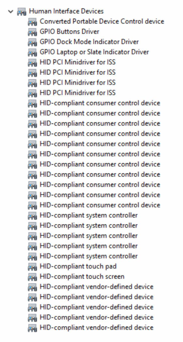
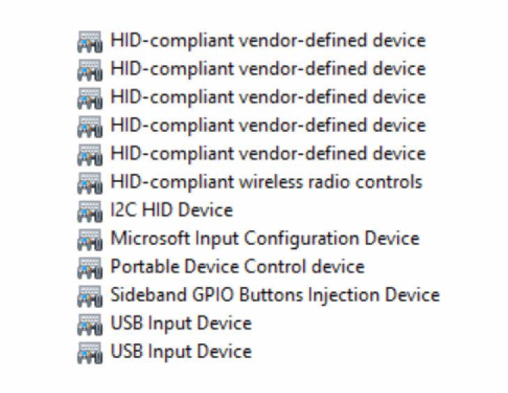
129 Intel Virtual Button driver Check if the Intel Virtual Button driver is installed by looking at Device Manager under System devices (shown below). Install the driver update from 129

130 Intel Wireless 3165 WiFi and Bluetooth drivers In the Device Manager, check if the network card driver is installed. Install the driver updates from In the Device Manager, check if the Bluetooth driver is installed. Install the driver updates from 130
Inspiron 22. Service Manual Series. Regulatory Model: W17B Regulatory Type: W17B001
 Inspiron 22 3000 Series Service Manual Regulatory Model: W17B Regulatory Type: W17B001 Notes, cautions, and warnings NOTE: A NOTE indicates important information that helps you make better use of your
XPS 15 2-in-1. Service Manual. Computer Model: XPS Regulatory Model: P73F Regulatory Type: P73F001
 XPS 15 2-in-1 Service Manual Computer Model: XPS 15-9575 Regulatory Model: P73F Regulatory Type: P73F001 Notes, cautions, and warnings NOTE: A NOTE indicates important information that helps you make better
Dell XPS 14z Owner s Manual
 Dell XPS 14z Owner s Manual Computer model: L412z Regulatory model: P24G series Regulatory type: P24G001 Notes, Cautions, and Warnings NOTE: A NOTE indicates important information that helps you make better
XPS 13 Convertible Service Manual
 XPS 13 Convertible Service Manual Computer Model: XPS 9365 Regulatory Model: P71G Regulatory Type: P71G001 Notes, cautions, and warnings NOTE: A NOTE indicates important information that helps you make
Dell XPS L702X Service Manual
 Dell XPS L702X Service Manual Regulatory model: P09E series Regulatory type: P09E002 Notes, Cautions, and Warnings NOTE: A NOTE indicates important information that helps you make better use of your computer.
Dell Inspiron N5110 Service Manual
 Dell Inspiron N5110 Service Manual Regulatory model: P17F Regulatory type: P17F001 Notes, Cautions, and Warnings NOTE: A NOTE indicates important information that helps you make better use of your computer.
Dell Edge Gateway. Service Manual Series
 Dell Edge Gateway 5000 Series Service Manual Computer Model: Dell Edge Gateway 5000/5100 Regulatory Model: N01G/N02G Regulatory Type: N01G001/N02G001 Notes, cautions, and warnings NOTE: A NOTE indicates
Service Manual - Memory Upgrade
 Inspiron 14 3000 Series Service Manual - Memory Upgrade Regulatory Model: P53G Regulatory Type: P53G002 Contents Before working inside your computer...3 Before you begin... 3 Safety instructions... 3 Recommended
Alienware Area-51 R5 Service Manual
 Alienware Area-51 R5 Service Manual Computer Model: Alienware Area-51 R5 Regulatory Model: D03X Regulatory Type: D03X002 Notes, cautions, and warnings NOTE: A NOTE indicates important information that
Dell Inspiron XPS and Inspiron 9100 Service Manual
 Dell Inspiron XPS and Inspiron 9100 Service Manual Dell Inspiron XPS and Inspiron 9100 Service Manual Before You Begin Memory Module, Mini PCI Card, and Devices System Components Subwoofer Bluetooth Card
Dell XPS M1530 Service Manual
 Dell XPS M1530 Service Manual Model PP28L www.dell.com support.dell.com Notes, Notices, and Cautions NOTE: A NOTE indicates important information that helps you make better use of your computer. NOTICE:
Alienware X51 Service Manual
 Alienware X51 Service Manual Computer Model: Alienware X51 R3 Regulatory Model: D05S Regulatory Type: D05S003 Notes, cautions, and warnings NOTE: A NOTE indicates important information that helps you make
Dell XPS M1730 Service Manual
 Dell XPS M1730 Service Manual Model PP06XA www.dell.com support.dell.com Notes, Notices, and Cautions NOTE: A NOTE indicates important information that helps you make better use of your computer. NOTICE:
Dell Alienware 13 R3 Heat-Sink Assembly
 Dell Alienware 13 R3 Heat-Sink Assembly Replacement In this guide, we will show you how to remove and replace the Heat-Sink Assembly. Written By: Teren Wallace ifixit CC BY-NC-SA www.ifixit.com Page 1
Thank you for purchasing this Factory Service Manual CD/DVD from servicemanuals4u.com.
 Thank you for purchasing this Factory Service Manual CD/DVD from servicemanuals4u.com. Please check out our ebay auctions for more great deals on Factory Service Manuals: servicemanuals4u Dell Inspiron
Thank you for purchasing this Factory Service Manual CD/DVD from servicemanuals4u.com.
 Thank you for purchasing this Factory Service Manual CD/DVD from servicemanuals4u.com. Please check out our ebay auctions for more great deals on Factory Service Manuals: servicemanuals4u Dell Latitude
Dell Latitude V710/V740 Service Manual
 Dell Latitude V710/V740 Service Manual Dell Latitude V710/V740 Service Manual Before You Begin Preparing to Work Inside the Computer Recommended Tools Computer Orientation Screw Identification System Components
Removing and Replacing Parts
 Removing and Replacing Parts Preparing to Work Inside the Computer Recommended Tools Screw Identification System Components Hard Drive Fixed Optical Drive Media Bay Devices Memory Modules Mini PCI Card
Dell Inspiron 660 Owner s Manual
 Dell Inspiron 660 Owner s Manual Computer model: Inspiron 660 Regulatory model: D11M Regulatory type: D11M002 Notes, Cautions, and Warnings NOTE: A NOTE indicates important information that helps you make
Thank you for purchasing this Factory Service Manual CD/DVD from servicemanuals4u.com.
 Thank you for purchasing this Factory Service Manual CD/DVD from servicemanuals4u.com. Please check out our ebay auctions for more great deals on Factory Service Manuals: servicemanuals4u Dell Inspiron
Dell Precision Owner's Manual. Regulatory Model: P60F Regulatory Type: P60F001
 Dell Precision 3520 Owner's Manual Regulatory Model: P60F Regulatory Type: P60F001 Notes, cautions, and warnings NOTE: A NOTE indicates important information that helps you make better use of your product.
Thank you for purchasing this Factory Service Manual CD/DVD from servicemanuals4u.com.
 Thank you for purchasing this Factory Service Manual CD/DVD from servicemanuals4u.com. Please check out our ebay auctions for more great deals on Factory Service Manuals: servicemanuals4u Dell Inspiron
Dell Precision M4600 Owner's Manual
 Dell Precision M4600 Owner's Manual Regulatory Model P13F Regulatory Type P13F001 Notes, Cautions, and Warnings NOTE: A NOTE indicates important information that helps you make better use of your computer.
ALIENWARE AURORA SERVICE MANUAL 01/
 ALIENWARE AURORA SERVICE MANUAL 01/ 01 Notes, Cautions, and Warnings NOTE: A NOTE indicates important information that helps you make better use of your computer. CAUTION: A CAUTION indicates either potential
Dell Latitude C800 Service Manual
 Dell Latitude C800 Service Manual Dell Latitude C800 Service Manual Before You Begin Preparing to Work Inside the Computer Recommended Tools Screw Identification Removing and Replacing Parts System Components
Dell Latitude Owner's Manual. Regulatory Model: P60F Regulatory Type: P60F001
 Dell Latitude 5580 Owner's Manual Regulatory Model: P60F Regulatory Type: P60F001 Notes, cautions, and warnings NOTE: A NOTE indicates important information that helps you make better use of your product.
Dell OptiPlex All-in-One. Stand Installation Guide
 Dell OptiPlex All-in-One Stand Installation Guide Notes, cautions, and warnings NOTE: A NOTE indicates important information that helps you make better use of your product. CAUTION: A CAUTION indicates
Written By: Teren Wallace
 In this guide, we will be showing you how to remove and replace the Touch Pad. Written By: Teren Wallace ifixit CC BY-NC-SA www.ifixit.com Page 1 of 26 INTRODUCTION In this guide, we will be showing you
Dell Latitude 14 Rugged 5414
 Dell Latitude 14 Rugged 5414 Owner's Manual Regulatory Model: P46G Regulatory Type: P46G002 Notes, cautions, and warnings NOTE: A NOTE indicates important information that helps you make better use of
Dell Latitude C800 SERVICE MANUAL. support.dell.com
 Dell Latitude C800 SERVICE MANUAL www.dell.com support.dell.com Dell Latitude C800 SERVICE MANUAL www.dell.com support.dell.com Notes, Notices, and Cautions NOTE: A NOTE indicates important information
Thank you for purchasing this Factory Service Manual CD/DVD from servicemanuals4u.com.
 Thank you for purchasing this Factory Service Manual CD/DVD from servicemanuals4u.com. Please check out our ebay auctions for more great deals on Factory Service Manuals: servicemanuals4u Dell Inspiron
Vostro Owner's Manual
 Vostro 14-5459 Owner's Manual Regulatory Model: P68G Regulatory Type: P68G001 Copyright 2015 Dell Inc. All rights reserved. This product is protected by U.S. and international copyright and intellectual
Dell Latitude 14 Rugged Extreme 7404 Owner's Manual
 Dell Latitude 14 Rugged Extreme 7404 Owner's Manual Regulatory Model: P45G Regulatory Type: P45G001 Notes, Cautions, and Warnings NOTE: A NOTE indicates important information that helps you make better
Dell Precision M2800 Owner's Manual
 Dell Precision M2800 Owner's Manual Regulatory Model: P29F Regulatory Type: P29F001 Notes, Cautions, and Warnings NOTE: A NOTE indicates important information that helps you make better use of your computer.
Dell Latitude Owner's Manual. Regulatory Model: P60F Regulatory Type: P60F001
 Dell Latitude 5580 Owner's Manual Regulatory Model: P60F Regulatory Type: P60F001 Notes, cautions, and warnings NOTE: A NOTE indicates important information that helps you make better use of your product.
Dell Latitude Owner's Manual. Regulatory Model: P27S Regulatory Type: P27S001
 Dell Latitude 5280 Owner's Manual Regulatory Model: P27S Regulatory Type: P27S001 Notes, cautions, and warnings NOTE: A NOTE indicates important information that helps you make better use of your product.
Dell Latitude Owner's Manual. Regulatory Model: P60F Regulatory Type: P60F001
 Dell Latitude 5580 Owner's Manual Regulatory Model: P60F Regulatory Type: P60F001 Notes, cautions, and warnings NOTE: A NOTE indicates important information that helps you make better use of your product.
Latitude Owner's Manual. Regulatory Model: P72G Regulatory Type: P72G003
 Latitude 5495 Owner's Manual Regulatory Model: P72G Regulatory Type: P72G003 Notes, cautions, and warnings NOTE: A NOTE indicates important information that helps you make better use of your product. CAUTION:
Dell Precision Owner's Manual. Regulatory Model: P60F Regulatory Type: P60F001
 Dell Precision 3520 Owner's Manual Regulatory Model: P60F Regulatory Type: P60F001 Notes, cautions, and warnings NOTE: A NOTE indicates important information that helps you make better use of your product.
Dell Latitude 5420/E5420/E5420m Owner's Manual
 Dell Latitude 5420/E5420/E5420m Owner's Manual Regulatory Model P15F Regulatory Type P15F001 Notes, Cautions, and Warnings NOTE: A NOTE indicates important information that helps you make better use of
SATADOM. for Dell PowerEdge R630, R730, and R730xd systems
 SATADOM for Dell PowerEdge R630, R730, and R730xd systems Notes, cautions, and warnings NOTE: A NOTE indicates important information that helps you make better use of your product. CAUTION: A CAUTION indicates
Dell Precision Mobile Workstation M6800 Owner's Manual
 Dell Precision Mobile Workstation M6800 Owner's Manual Regulatory Model: P30F Regulatory Type: P30F001 Copyright 2015 Dell Inc. All rights reserved. This product is protected by U.S. and international
Dell Latitude D500 Service Manual
 Dell Latitude D500 Service Manual Dell Latitude D500 Service Manual Before You Begin Preparing to Work Inside the Computer Recommended Tools Computer Orientation Screw Identification Memory Module, Mini
Dell Latitude 3560 Owner's Manual
 Dell Latitude 3560 Owner's Manual Regulatory Model: P50F Regulatory Type: P50F001 Notes, cautions, and warnings NOTE: A NOTE indicates important information that helps you make better use of your computer.
Hardware Replacement Guide Types 8099, 8116, 8155, 8156 Types 8157, 8158, 8159, 8160 Types 8215, 9210, 9211
 Hardware Replacement Guide Types 8099, 8116, 8155, 8156 Types 8157, 8158, 8159, 8160 Types 8215, 9210, 9211 Hardware Replacement Guide Types 8099, 8116, 8155, 8156 Types 8157, 8158, 8159, 8160 Types 8215,
Dell Vostro Owner's Manual. Regulatory Model: P63F Regulatory Type: P63F002
 Dell Vostro 15 3568 Owner's Manual Regulatory Model: P63F Regulatory Type: P63F002 Notes, cautions, and warnings NOTE: A NOTE indicates important information that helps you make better use of your product.
Dell Latitude E5540 Owner's Manual
 Dell Latitude E5540 Owner's Manual Regulatory Model: P44G Regulatory Type: P44G001 Notes, Cautions, and Warnings NOTE: A NOTE indicates important information that helps you make better use of your computer.
Dell Vostro Owner's Manual. Regulatory Model: P63F Regulatory Type: P63F002
 Dell Vostro 15 3568 Owner's Manual Regulatory Model: P63F Regulatory Type: P63F002 Notes, cautions, and warnings NOTE: A NOTE indicates important information that helps you make better use of your product.
Dell Latitude Owner's Manual. Regulatory Model: P63G Regulatory Type: P63G001
 Dell Latitude 3470 Owner's Manual Regulatory Model: P63G Regulatory Type: P63G001 Notes, cautions, and warnings NOTE: A NOTE indicates important information that helps you make better use of your computer.
Dell Precision Owner's Manual. Regulatory Model: P53F Regulatory Type: P53F002
 Dell Precision 7520 Owner's Manual Regulatory Model: P53F Regulatory Type: P53F002 Notes, cautions, and warnings NOTE: A NOTE indicates important information that helps you make better use of your product.
Dell Latitude Owner's Manual. Regulatory Model: P63G Regulatory Type: P63G001
 Dell Latitude 3460 Owner's Manual Regulatory Model: P63G Regulatory Type: P63G001 Notes, cautions, and warnings NOTE: A NOTE indicates important information that helps you make better use of your computer.
Dell Latitude E6430 / E6430 ATG Owner's Manual
 Dell Latitude E6430 / E6430 ATG Owner's Manual Regulatory Model: P25G Regulatory Type: P25G001, P25G002 Notes, Cautions, and Warnings NOTE: A NOTE indicates important information that helps you make better
Hardware Replacement Guide
 Hardware Replacement Guide Types 6491, 8013, 8702, 8706 Types 8716, 8970, 8972, 8976 Types 8980, 8982, 8986, 8992 Types 8994, 9266, 9276, 9278 Types 9282, 9286, 9288, 9374 Types 9378, 9380, 9384, 9628
Dell Latitude Owner's Manual. Regulatory Model: P73G Regulatory Type: P73G001
 Dell Latitude 7480 Owner's Manual Regulatory Model: P73G Regulatory Type: P73G001 Notes, cautions, and warnings NOTE: A NOTE indicates important information that helps you make better use of your product.
Vostro Owner's Manual. Regulatory Model: P75G Regulatory Type: P75G001
 Vostro 14-5468 Owner's Manual Regulatory Model: P75G Regulatory Type: P75G001 2016 2018 Dell Inc. or its subsidiaries. All rights reserved. Dell, EMC, and other trademarks are trademarks of Dell Inc. or
ThinkCentre Hardware Installation and Replacement Guide. Machine Types 6062, 6065, 6071, 6076, 6089, 7103, 9011, 9014, 9071, 9089, 9162, 9182, 9303
 ThinkCentre Hardware Installation and Replacement Guide Machine Types 6062, 6065, 6071, 6076, 6089, 7103, 9011, 9014, 9071, 9089, 9162, 9182, 9303 ThinkCentre Hardware Installation and Replacement Guide
Dell Latitude 3460 Owner's Manual
 Dell Latitude 3460 Owner's Manual Regulatory Model: P63G Regulatory Type: P63G001 Notes, cautions, and warnings NOTE: A NOTE indicates important information that helps you make better use of your computer.
Dell Latitude 3550 Owner's Manual
 Dell Latitude 3550 Owner's Manual Regulatory Model: P38F Regulatory Type: P38F001 Notes, cautions, and warnings NOTE: A NOTE indicates important information that helps you make better use of your computer.
To connect the AC adapter:
 Replacing the AC Adapter Replacing the AC Adapter 3 Plug the power cord into a wall outlet. The power indicator turns on. To connect the AC adapter: Connect the power cord to the AC adapter. Power indicator
Serial ATA Hot Swap Drive Cage Upgrade Kit for: Intel Server Chassis SC5200 Intel Server Chassis SC5250-E
 Serial ATA Hot Swap Drive Cage Upgrade Kit for: Intel Server Chassis SC5200 Intel Server Chassis SC5250-E A Guide for Technically Qualified Assemblers of Intel Identified Subassemblies/Products Order Number:
Dell Vostro 3252 Owner's Manual
 Dell Vostro 3252 Owner's Manual Regulatory Model: D14S Regulatory Type: D14S001 Notes, cautions, and warnings NOTE: A NOTE indicates important information that helps you make better use of your computer.
Upgrading and Servicing Guide
 Upgrading and Servicing Guide Copyright Information The only warranties for Hewlett-Packard products and services are set forth in the express statements accompanying such products and services. Nothing
Dell Latitude Owner's Manual. Regulatory Model: P73G Regulatory Type: P73G001
 Dell Latitude 7480 Owner's Manual Regulatory Model: P73G Regulatory Type: P73G001 Notes, cautions, and warnings NOTE: A NOTE indicates important information that helps you make better use of your product.
Dell Vostro Owner's Manual
 Dell Vostro 20 3052 Owner's Manual Regulatory Model: W15B Regulatory Type: W15B002 Notes, cautions, and warnings NOTE: A NOTE indicates important information that helps you make better use of your computer.
Intel NUC Kit DN2820FYKH User Guide. Intel NUC Kit DN2820FYKH User Guide
 Intel NUC Kit DN2820FYKH User Guide 1 Before You Begin CAUTIONS The procedures in this user guide assume familiarity with the general terminology associated with personal computers and with the safety
Intel NUC Kit DC53427HYE User Guide. Intel NUC Kit DC53427HYE
 Intel NUC Kit DC53427HYE User Guide 1 Before You Begin CAUTIONS The procedures in this user guide assume familiarity with the general terminology associated with personal computers and with the safety
Intel NUC Kit D54250WYKH & D34010WYKH User Guide. Intel NUC Kit D54250WYKH Intel NUC Kit D34010WYKH User Guide
 Intel NUC Kit D54250WYKH Intel NUC Kit D34010WYKH User Guide 1 Before You Begin CAUTIONS The procedures in this user guide assume familiarity with the general terminology associated with personal computers
Dell Precision 3510 Owner's Manual
 Dell Precision 3510 Owner's Manual Regulatory Model: P48F Regulatory Type: P48F001 Notes, cautions, and warnings NOTE: A NOTE indicates important information that helps you make better use of your computer.
Dell OptiPlex 7440 All-In-One Owner's Manual
 Dell OptiPlex 7440 All-In-One Owner's Manual Regulatory Model: W11C Regulatory Type: W11C001 Notes, cautions, and warnings NOTE: A NOTE indicates important information that helps you make better use of
Dell Inspiron System Board
 Dell Inspiron 17-5749 System Board Replacement This guide will instruct users on the procedure of removing/replacing the Dell Inspiron 17-5749 system board. Written By: Christopher Tran ifixit CC BY-NC-SA
Dell Precision Service Manual. Regulatory Model: P74F Regulatory Type: P74F001
 Dell Precision 7530 Service Manual Regulatory Model: P74F Regulatory Type: P74F001 Notes, cautions, and warnings NOTE: A NOTE indicates important information that helps you make better use of your product.
Installation Guide. Copyright 2005 MSI Computer Corp.
 Installation Guide Copyright 2005 MSI Computer Corp. Overview: 1013 is shipped out as a barebone. Some of the components are equipped while some are not. This installation guide provides you with the information
Dell Precision Workstation T7610 Owner's Manual
 Dell Precision Workstation T7610 Owner's Manual Regulatory Model: D02X Regulatory Type: D02X002 Notes, Cautions, and Warnings NOTE: A NOTE indicates important information that helps you make better use
Dell Latitude E5570 Owner's Manual
 Dell Latitude E5570 Owner's Manual Regulatory Model: P48F Regulatory Type: P48F001 Notes, cautions, and warnings NOTE: A NOTE indicates important information that helps you make better use of your computer.
Dell Precision M6400 Service Manual
 Dell Precision M6400 Service Manual Dell Precision M6400 Service Manual Troubleshooting Working on Your Computer Base Assembly Hard Drive Optical Drive WLAN/WiMax Card WWAN Card UWB WPAN Card and WPAN
Dell Precision 3430 Small Form Factor
 Dell Precision 3430 Small Form Factor USB Type-C card Installation Guide Regulatory Model: D11S Regulatory Type: D11S004 Notes, cautions, and warnings NOTE: A NOTE indicates important information that
Dell Vostro 3250 Owner's Manual
 Dell Vostro 3250 Owner's Manual Regulatory Model: D13S Regulatory Type: D13S001 Notes, cautions, and warnings NOTE: A NOTE indicates important information that helps you make better use of your computer.
H4 Series Hardware Replacement Guide
 Machine type: 10059/7723 10060/7724 10068/7752 10080/3099/1194 10091/2558/1196 H4 Series Hardware Replacement Guide Version 3.0 2011.08 31500379 Hardware Replacement Guide Copyright Lenovo 2011. All rights
Dell TM XFR D630. Fully Rugged Notebook. Service Manual
 Dell TM XFR D630 Fully Rugged Notebook Service Manual Notes, Notices, and Cautions NOTE: A NOTE indicates important information that helps you make better use of your computer. NOTICE: A NOTICE indicates
Intel NUC Kit NUC5i3MYHE & NUC5i5MYHE User Guide. Intel NUC Kit NUC5i3MYHE Intel NUC Kit NUC5i5MYHE User Guide
 Intel NUC Kit NUC5i3MYHE Intel NUC Kit NUC5i5MYHE User Guide 1 Before You Begin CAUTIONS The procedures in this user guide assume familiarity with the general terminology associated with personal computers
Dell Latitude E5470 Owner's Manual
 Dell Latitude E5470 Owner's Manual Regulatory Model: P62G Regulatory Type: P62G001 Notes, cautions, and warnings NOTE: A NOTE indicates important information that helps you make better use of your computer.
Installing System Board Options
 CHAPTER 8 Installing System Board Options This section describes how to install the following options: Expansion cards Memory modules Microprocessor This section also includes instructions for replacing
Dell Latitude E6420 XFR
 Dell Latitude E6420 XFR Service Manual www.dell.com support.dell.com Notes, Notices, and Cautions NOTE: A NOTE indicates important information that helps you make better use of your computer. NOTICE: A
Dell OptiPlex 7440 All-In-One Owner's Manual
 Dell OptiPlex 7440 All-In-One Owner's Manual Regulatory Model: W11C Regulatory Type: W11C001 Notes, cautions, and warnings NOTE: A NOTE indicates important information that helps you make better use of
Latitude in-1. Owner's Manual. Regulatory Model: P29S Regulatory Type: P29S001
 Latitude 5289 2-in-1 Owner's Manual Regulatory Model: P29S Regulatory Type: P29S001 Notes, cautions, and warnings NOTE: A NOTE indicates important information that helps you make better use of your product.
Dell Vostro 5480 Owner's Manual
 Dell Vostro 5480 Owner's Manual Regulatory Model: P41G Regulatory Type: P41G002 Notes, Cautions, and Warnings NOTE: A NOTE indicates important information that helps you make better use of your computer.
Dell Vostro 3250 Owner's Manual
 Dell Vostro 3250 Owner's Manual Regulatory Model: D13S Regulatory Type: D13S001 Notes, cautions, and warnings NOTE: A NOTE indicates important information that helps you make better use of your computer.
Dell Vostro Service Manual. Regulatory Model: P77F Regulatory Type: P77F001
 Dell Vostro 5581 Service Manual Regulatory Model: P77F Regulatory Type: P77F001 Notes, cautions, and warnings NOTE: A NOTE indicates important information that helps you make better use of your product.
Dell OptiPlex 7460 All-in-One. Intel Optane card installation guide
 Dell OptiPlex 7460 All-in-One Intel Optane card installation guide Notes, cautions, and warnings NOTE: A NOTE indicates important information that helps you make better use of your product. CAUTION: A
Upgrading and Servicing Guide
 Upgrading and Servicing Guide Copyright Information The only warranties for Hewlett-Packard products and services are set forth in the express statements accompanying such products and services. Nothing
Dell Vostro Owner's Manual
 Dell Vostro 24 5460 Owner's Manual Regulatory Model: W12C Regulatory Type: W12C007 Notes, cautions, and warnings NOTE: A NOTE indicates important information that helps you make better use of your computer.
Replacement Instructions
 apple PowerBook G4 Memory Replacement Instructions Be sure to follow the instructions in this sheet carefully. Failure to follow these instructions could result in damage to your equipment and may void
M710s. User Guide and Hardware Maintenance Manual. Overview. Specifications. Locking the computer. Replacing hardware. Replacing CRUs.
 M710s User Guide and Hardware Maintenance Manual Machine Type (MT): 10M7, 10M8, 10QT, 10R7 Energy Star MT: 10M7, 10M8, 10QT, 10R7 Overview Specifications Locking the computer Locations of indicators, connectors,
Dell Latitude Owner's Manual. Regulatory Model: P72G Regulatory Type: P72G001
 Dell Latitude 5480 Owner's Manual Regulatory Model: P72G Regulatory Type: P72G001 Notes, cautions, and warnings NOTE: A NOTE indicates important information that helps you make better use of your product.
Lenovo V330-20ICB AIO User Guide and Hardware Maintenance Manual
 Lenovo V330-20ICB AIO User Guide and Hardware Maintenance Manual Energy Star Machine Types: 10UK and 10UL Note: Before using this information and the product it supports, be sure to read and understand
V520S. User Guide and Hardware Maintenance Manual. Specifications. Overview. Computer locks. Replacing CRUs. Replacing FRUs.
 V520S User Guide and Hardware Maintenance Manual Machine Type (MT): 10NM, 10NN Energy Star MT: 10NM, 10NN Overview Specifications Computer locks Locations of indicators, connectors, and controls provided
Dell Latitude E5470. Owner's Manual. Regulatory Model: P62G Regulatory Type: P62G001
 Dell Latitude E5470 Owner's Manual Regulatory Model: P62G Regulatory Type: P62G001 Notes, cautions, and warnings NOTE: A NOTE indicates important information that helps you make better use of your product.
User Guide for NUC8i5BEK, NUC8i3BEK. Intel NUC Kit NUC8i5BEK Intel NUC Kit NUC8i3BEK. User Guide
 Intel NUC Kit NUC8i5BEK Intel NUC Kit NUC8i3BEK User Guide 1 Before You Begin CAUTIONS The steps in this guide assume you re familiar with computer terminology and with the safety practices and regulatory
apple Service Source PowerBook G4 Updated 8 July Apple Computer, Inc. All rights reserved.
 apple Service Source PowerBook G4 Updated 8 July 2003 2003 Apple Computer, Inc. All rights reserved. apple Service Source Take Apart PowerBook G4 2003 Apple Computer, Inc. All rights reserved. apple PowerBook
Machine Type (MT): Energy Star MT:
: Energy Star MT:") M70t User Guide and Hardware Maintenance Manual Machine Type (MT): 0M9, 0MA, 0QK, 0R8 Energy Star MT: 0M9, 0MA, 0QK, 0R8 Overview Specifications Locking the computer Locations of indicators, connectors,
M70t User Guide and Hardware Maintenance Manual Machine Type (MT): 0M9, 0MA, 0QK, 0R8 Energy Star MT: 0M9, 0MA, 0QK, 0R8 Overview Specifications Locking the computer Locations of indicators, connectors,