Dell Latitude 5420/E5420/E5420m Owner's Manual
|
|
|
- Joella Underwood
- 5 years ago
- Views:
Transcription
1 Dell Latitude 5420/E5420/E5420m Owner's Manual Regulatory Model P15F Regulatory Type P15F001
2 Notes, Cautions, and Warnings NOTE: A NOTE indicates important information that helps you make better use of your computer. CAUTION: A CAUTION indicates potential damage to hardware or loss of data if instructions are not followed. WARNING: A WARNING indicates a potential for property damage, personal injury, or death. Information in this publication is subject to change without notice Dell Inc. All rights reserved. Reproduction of these materials in any manner whatsoever without the written permission of Dell Inc. is strictly forbidden. Trademarks used in this text: Dell, the DELL logo, Dell Precision, Precision ON,ExpressCharge, Latitude, Latitude ON, OptiPlex, Vostro, and Wi-Fi Catcher are trademarks of Dell Inc. Intel, Pentium, Xeon, Core, Atom, Centrino, and Celeron are registered trademarks or trademarks of Intel Corporation in the U.S. and other countries. AMD is a registered trademark and AMD Opteron, AMD Phenom, AMD Sempron, AMD Athlon, ATI Radeon, and ATI FirePro are trademarks of Advanced Micro Devices, Inc. Microsoft, Windows, MS-DOS, Windows Vista, the Windows Vista start button, and Office Outlook are either trademarks or registered trademarks of Microsoft Corporation in the United States and/or other countries. Blu-ray Disc is a trademark owned by the Blu-ray Disc Association (BDA) and licensed for use on discs and players. The Bluetooth word mark is a registered trademark and owned by the Bluetooth SIG, Inc. and any use of such mark by Dell Inc. is under license. Wi-Fi is a registered trademark of Wireless Ethernet Compatibility Alliance, Inc. Other trademarks and trade names may be used in this publication to refer to either the entities claiming the marks and names or their products, Dell Inc. disclaims any proprietary interest in trademarks and trade names other than its own
3 Contents Notes, Cautions, and Warnings Working on Your Computer...9 Before Working Inside Your Computer...9 Recommended Tools...10 Turning Off Your Computer...11 After Working Inside Your Computer Battery...13 Removing the Battery...13 Installing the Battery PC Card...15 Removing the PC Card...15 Installing the PC Card Secure Digital (SD) Card...17 Removing The Secure Digital (SD) Card...17 Installing The Secure Digital (SD) Card Subscriber Identity Module (SIM) Card...19 Removing the Subscriber Identity Module (SIM) Card...19 Installing the Subscriber Identity Module (SIM) Card ExpressCard...21 Removing the ExpressCard...21 Installing the ExpressCard Back Panel...23 Removing the Back Panel...23
4 Installing the Back Panel Keyboard Trim...25 Removing the Keyboard Trim...25 Installing the Keyboard Trim Keyboard...27 Removing the Keyboard...27 Installing the Keyboard Optical Drive...35 Removing the Optical Drive...35 Installing the Optical Drive Hard Drive...37 Removing the Hard Drive...37 Installing the Hard Drive Wireless Local Area Network (WLAN) Card...41 Removing the Wireless Local Area Network (WLAN) Card...41 Installing The Wireless Local Area Network (WLAN) Card Wireless Wide Area Network (WWAN) Card...43 Removing the Wireless Wide Area Network (WWAN) Card...43 Installing The Wireless Wide Area Network (WWAN) Card Memory...45 Removing the Memory Module...45 Installing the Memory Module CPU Door...47 Removing the CPU Door...47 Installing the CPU Door...49
5 16 Heat Sink...51 Removing The Heat Sink...51 Installing the Heat Sink Processor...53 Removing the Processor...53 Installing the Processor Palm Rest...55 Removing the Palm Rest...55 Installing the Palm Rest LED Board...63 Removing the LED Board...63 Installing the LED Board ExpressCard/Smart Card/PCMCIA Module...69 Removing the ExpressCard/Smart Card/PCMCIA Module...69 Installing the ExpressCard/Smart Card/PCMCIA Module Bluetooth Card...75 Removing the Bluetooth Card...75 Installing the Bluetooth Card Display Assembly...81 Removing the Display Assembly...81 Installing the Display Assembly Brackets...89 Removing the Support Brackets...89 Installing the Support Brackets Modem Card...95 Removing the Modem Card...95
6 Installing the Modem Card Audio Board Removing the Audio Board Installing the Audio Board System Board Removing the System Board Installing the System Board Coin-Cell Battery Removing the Coin-Cell Battery Installing the Coin-Cell Battery Input/Output Panel Removing The Input/Output (I/O) Panel Installing the Input/Output (I/O) Panel Power Connector Removing the Power Connector Installing the Power Connector Modem Connector Removing the Modem Connector Installing the Modem Connector Thermal Fan Removing the Thermal Fan Installing the Thermal Fan Speaker Removing the Speakers Installing the Speakers...139
7 33 Display Bezel Removing the Display Bezel Installing the Display Bezel Display Panel Removing the Display Panel Installing the Display Panel Display Hinges Removing the Display Hinges Installing the Display Hinges Camera Removing the Camera Module Installing the Camera Module Specifications Technical Specifications System Setup Overview Entering System Setup System Setup Options Diagnostics Diagnostics Contacting Dell Contacting Dell...175
8 8
9 Working on Your Computer 1 Before Working Inside Your Computer Use the following safety guidelines to help protect your computer from potential damage and to help to ensure your personal safety. Unless otherwise noted, each procedure included in this document assumes that the following conditions exist: You have performed the steps in Working on Your Computer. You have read the safety information that shipped with your computer. A component can be replaced or--if purchased separately--installed by performing the removal procedure in reverse order. WARNING: Before working inside your computer, read the safety information that shipped with your computer. For additional safety best practices information, see the Regulatory Compliance Homepage at CAUTION: Many repairs may only be done by a certified service technician. You should only perform troubleshooting and simple repairs as authorized in your product documentation, or as directed by the online or telephone service and support team. Damage due to servicing that is not authorized by Dell is not covered by your warranty. Read and follow the safety instructions that came with the product. CAUTION: To avoid electrostatic discharge, ground yourself by using a wrist grounding strap or by periodically touching an unpainted metal surface, such as a connector on the back of the computer. CAUTION: Handle components and cards with care. Do not touch the components or contacts on a card. Hold a card by its edges or by its metal mounting bracket. Hold a component such as a processor by its edges, not by its pins. CAUTION: When you disconnect a cable, pull on its connector or on its pull-tab, not on the cable itself. Some cables have connectors with locking tabs; if you are disconnecting this type of cable, press in on the locking tabs before you disconnect the cable. As you pull connectors apart, keep them evenly aligned to avoid bending any connector pins. Also, before you connect a cable, ensure that both connectors are correctly oriented and aligned. 9
10 NOTE: The color of your computer and certain components may appear differently than shown in this document. To avoid damaging your computer, perform the following steps before you begin working inside the computer. 1. Ensure that your work surface is flat and clean to prevent the computer cover from being scratched. 2. Turn off your computer (see Turning Off Your Computer). 3. If the computer is connected to a docking device (docked) such as the optional Media Base or Battery Slice, undock it. CAUTION: To disconnect a network cable, first unplug the cable from your computer and then unplug the cable from the network device. 4. Disconnect all network cables from the computer. 5. Disconnect your computer and all attached devices from their electrical outlets. 6. Close the display and turn the computer upside-down on a flat work surface. NOTE: To avoid damaging the system board, you must remove the main battery before you service the computer. 7. Remove the main battery (see Battery). 8. Turn the computer top-side up. 9. Open the display. 10. Press the power button to ground the system board. CAUTION: To guard against electrical shock, always unplug your computer from the electrical outlet before opening the display. CAUTION: Before touching anything inside your computer, ground yourself by touching an unpainted metal surface, such as the metal at the back of the computer. While you work, periodically touch an unpainted metal surface to dissipate static electricity, which could harm internal components. 11. Remove any installed ExpressCards or Smart Cards from the appropriate slots. Recommended Tools The procedures in this document may require the following tools: Small flat-blade screwdriver 10
11 #0 Phillips screwdriver #1 Phillips screwdriver Small plastic scribe Flash BIOS update program CD Turning Off Your Computer CAUTION: To avoid losing data, save and close all open files and exit all open programs before you turn off your computer. 1. Shut down the operating system: In Windows Vista : Click Start, then click the arrow in the lower-right corner of the Start menu as shown below, and then click Shut Down. In Windows XP: Click Start Turn Off Computer Turn Off. The computer turns off after the operating system shutdown process is complete. 2. Ensure that the computer and all attached devices are turned off. If your computer and attached devices did not automatically turn off when you shut down your operating system, press and hold the power button for about 4 seconds to turn them off. After Working Inside Your Computer After you complete any replacement procedure, ensure you connect any external devices, cards, and cables before turning on your computer. CAUTION: To avoid damage to the computer, use only the battery designed for this particular Dell computer. Do not use batteries designed for other Dell computers. 1. Connect any external devices, such as a port replicator, battery slice, or media base, and replace any cards, such as an ExpressCard. 2. Connect any telephone or network cables to your computer. 11
12 CAUTION: To connect a network cable, first plug the cable into the network device and then plug it into the computer. 3. Replace the battery. 4. Connect your computer and all attached devices to their electrical outlets. 5. Turn on your computer. 12
13 Battery 2 Removing the Battery 1. Follow the procedures in Before Working On Your Computer. 2. Slide the release latches to unlock the battery. 3. Remove the battery from the computer. Installing the Battery 1. Slide the battery back into the computer. The release latches automatically click into the lock position. 2. Follow the procedures in After Working Inside Your Computer. 13
14 14
15 PC Card 3 Removing the PC Card 1. Follow the procedures in Before Working On Your Computer. 2. Press in on the PC latch to release the latch. 3. Press in on the PC latch to release the PC card. 4. Slide the PC card out of the computer. 15

16 Installing the PC Card 1. Push the PC latch to lock it. 2. Push the PC card to its slot until it clicks. 3. Follow the procedures in After Working Inside Your Computer. 16


17 Secure Digital (SD) Card 4 Removing The Secure Digital (SD) Card 1. Follow the procedures in Before Working On Your Computer. 2. Push in on the SD card. 3. Slide the SD card out of the computer. Installing The Secure Digital (SD) Card 1. Slide the SD card into its slot until it clicks into place. 2. Follow the procedures in After Working Inside Your Computer. 17
18 18

19 Subscriber Identity Module (SIM) Card 5 Removing the Subscriber Identity Module (SIM) Card 1. Follow the procedures in Before Working On Your Computer. 2. Remove the battery. 3. Press and release the SIM card located on the battery wall. 4. Slide the SIM card from the computer. 19
20 Installing the Subscriber Identity Module (SIM) Card 1. Insert the SIM card into the slot. 2. Replace the battery. 3. Follow the procedures in After Working Inside Your Computer. 20
21 ExpressCard 6 Removing the ExpressCard 1. Follow the procedures in Before Working On Your Computer. 2. Push in on the ExpressCard. 3. Slide the ExpressCard out of the computer. Installing the ExpressCard 1. Insert the ExpressCard into the slot until it clicks into place. 2. Follow the procedures in After Working Inside Your Computer. 21
22 22
23 Back Panel 7 Removing the Back Panel 1. Follow the procedures in Before Working On Your Computer. 2. Remove the battery. 3. Remove the screws that secure the back panel. 4. Slide and remove the back panel toward the front of the computer. Installing the Back Panel 1. Slide the back panel towards the back of the computer. 2. Tighten the screws to secure the back panel. 3. Replace the battery. 4. Follow the procedures in After Working Inside Your Computer. 23
24 24
25 Keyboard Trim 8 Removing the Keyboard Trim 1. Follow the procedures in Before Working On Your Computer. 2. Remove the battery. 3. Pry up the keyboard trim from the bottom edge. 4. Pry up the keyboard trim from the top edge. 5. Remove the keyboard trim from the computer. 25

26 Installing the Keyboard Trim 1. Align the keyboard trim with the tabs on the top of the palm rest. 2. Press along the top edge to latch on the tabs. 3. Work your way around the sides and bottom edge of the keyboard trim. 4. Press the keyboard trim down along all the edges until it clicks into place. 5. Replace the battery. 6. Follow the procedures in After Working Inside Your Computer. 26
27 Keyboard 9 Removing the Keyboard 1. Follow the procedures in Before Working On Your Computer. 2. Remove the battery. 3. Remove the keyboard trim. 4. Remove the screws that secure the keyboard to the front of the computer. 27

28 5. Flip the computer and remove the screws that secure the keyboard to the computer. 28

29 6. Flip the keyboard. 29

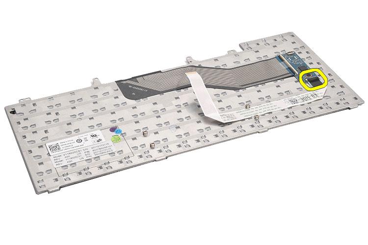
30 7. Disconnect the keyboard data cable from the computer. 30
31 8. Remove the keyboard from the computer. 31

32 9. Disconnect and remove the cable from the keyboard. 32
33 33
34 Installing the Keyboard 1. Connect the keyboard-data cable to the system board. 2. Connect the keyboard data cable to the back of the keyboard. 3. Replace the tape to secure the keyboard data cable to the back of the keyboard. 4. Replace the keyboard on the palm rest to align with the screw holes. 5. Tighten the keyboard screws. 6. Flip the keyboard and tighten the screws. 7. Replace the keyboard trim. 8. Replace the battery. 9. Follow the procedures in After Working Inside Your Computer. 34

35 Optical Drive 10 Removing the Optical Drive 1. Follow the procedures in Before Working On Your Computer. 2. Remove the battery. 3. Remove the back panel. 4. Remove the screw that secures the optical drive to the computer. 5. Push the screw tab away from the computer to release the optical drive from the drive bay. 6. Remove the optical drive from the computer. 35

36 Installing the Optical Drive 1. Slide the optical drive into the drive bay on the right side of the computer. 2. Tighten the screw on the back of the computer to secure the optical drive. 3. Replace the back panel. 4. Replace the battery. 5. Follow the procedures in After Working Inside Your Computer. 36
37 Hard Drive 11 Removing the Hard Drive 1. Follow the procedures in Before Working On Your Computer. 2. Remove the battery. 3. Remove the back panel. 4. Remove the screws that secure the hard-drive bracket to the computer. 5. Use the tab to pull the hard-drive bracket upward and remove it from the computer. 6. Remove the hard-drive bracket screws. 37

38 7. Disconnect the bracket from the hard drive. 8. Disconnect the hard-drive connector from the hard drive. 38
39 Installing the Hard Drive 1. Reconnect the hard-drive connector to the hard drive. 2. Attach the hard-drive bracket to the hard drive. 3. Tighten the hard-drive bracket screws to ensure that the bracket is correctly aligned and holding the hard drive. 4. Slide the hard drive into the bay towards the connector on the system board. 5. Tighten the screws to secure the hard drive. 6. Replace the back panel. 7. Replace the battery. 8. Follow the procedures in After Working Inside Your Computer. 39
40 40

41 Wireless Local Area Network (WLAN) Card 12 Removing the Wireless Local Area Network (WLAN) Card 1. Follow the procedures in Before Working On Your Computer. 2. Remove the battery. 3. Remove the back panel. 4. Disconnect the antenna cables from the WLAN card. 5. Remove the screw that secures the WLAN card to system board. 6. Remove the WLAN card. 41
42 Installing The Wireless Local Area Network (WLAN) Card 1. Slide the WLAN card into its slot. 2. Tighten the screw to secure the WLAN card to the computer. 3. Connect the antenna cables according to the color code on the WLAN card. 4. Replace the back panel. 5. Replace the battery. 6. Follow the procedures in After Working Inside Your Computer. 42
43 Wireless Wide Area Network (WWAN) Card 13 Removing the Wireless Wide Area Network (WWAN) Card 1. Follow the procedures in Before Working On Your Computer. 2. Remove the battery. 3. Remove the back panel. 4. Disconnect the antenna cables from the WWAN card. 5. Remove the screw that secures the WWAN card to the system board. 6. Remove the WWAN card. 43

44 Installing The Wireless Wide Area Network (WWAN) Card 1. Slide the WWAN card into its slot. 2. Tighten the screw to secure the WWAN card to the computer. 3. Connect the antenna cables according to the color code on the WWAN card. 4. Replace the back panel. 5. Replace the battery. 6. Follow the procedures in After Working Inside Your Computer. 44

45 Memory 14 Removing the Memory Module 1. Follow the procedures in Before Working On Your Computer. 2. Remove the battery. 3. Remove the back panel. 4. Pry the retention clips away from the memory module. 5. Remove the memory module from the computer. 45
46 Installing the Memory Module 1. Insert the memory module into the slot in the computer. 2. Press down the memory module until the retention clips secure the memory module. 3. Replace the back panel. 4. Replace the battery. 5. Follow the procedures in After Working Inside Your Computer. 46
47 CPU Door 15 Removing the CPU Door 1. Follow the procedures in Before Working On Your Computer. 2. Remove the battery. 3. Remove the back panel. 4. Remove the screws that secure the CPU door to the computer. 47

48 5. Remove the CPU door. 48
49 Installing the CPU Door 1. Slide the CPU door downwards and towards the back of the computer. 2. Tighten the screws to secure the CPU door. 3. Replace the back panel. 4. Replace the battery. 5. Follow the procedures in After Working Inside Your Computer. 49
50 50
51 Heat Sink 16 Removing The Heat Sink 1. Follow the procedures in Before Working On Your Computer. 2. Remove the battery. 3. Remove the back panel. 4. Remove the CPU door. 5. Loosen the screws on the heat sink. 6. Lift the heat sink and remove it from the computer. Installing the Heat Sink 1. Tighten the screws as per the numerical sequence on the heat sink module. 51
52 Ensure that the heat sink is correctly aligned and seated over the processor. 2. Replace the CPU door. 3. Replace the back panel. 4. Replace the battery. 5. Follow the procedures in After Working Inside Your Computer. 52
53 Processor 17 Removing the Processor 1. Follow the procedures in Before Working On Your Computer. 2. Remove the battery. 3. Remove the back panel. 4. Remove the CPU door. 5. Remove the heat sink. 6. Rotate the processor-cam screw in counter-clockwise direction. 7. Remove the processor. 53
54 Installing the Processor 1. Insert the processor into the processor socket. 2. Replace the heat sink. 3. Replace the CPU door. 4. Replace the back panel. 5. Replace the battery. 6. Follow the procedures in After Working Inside Your Computer. 54
55 Palm Rest 18 Removing the Palm Rest 1. Follow the procedures in Before Working On Your Computer. 2. Remove the battery. 3. Remove the back panel. 4. Remove the keyboard trim. 5. Remove the keyboard. 6. Remove the optical drive. 7. Remove the CPU door. 8. Remove the screws from the bottom of the computer. 55
56 9. Flip the computer and remove the screws from the back of the computer. 56
57 10. Disconnect the following cables from the computer: power button cable fingerprint cable touchpad cable 57
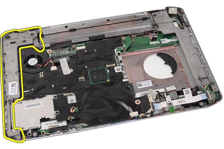
58 11. Lift up the left edge of the palm rest assembly. 58

59 12. Release the tabs on the right edge of the palm rest assembly. 59
60 13. Remove the palm rest assembly from the computer. 60
61 Installing the Palm Rest 1. From the left edge of the palm rest, press the palm rest downwards on all the edges on the computer. 2. Press down on all edges to ensure that the tabs are engaged. 3. Connect the following cables to the system board: power button cable fingerprint cable 61
62 touchpad cable 4. Tighten the screws to secure the palm rest. 5. Flip the computer over and tighten the screws to secure the palm rest. 6. Replace the CPU door. 7. Replace the keyboard. 8. Replace the keyboard trim. 9. Replace the optical drive. 10. Replace the back panel. 11. Replace the battery. 12. Follow the procedures in After Working Inside Your Computer. 62
63 LED Board 19 Removing the LED Board 1. Follow the procedures in Before Working On Your Computer. 2. Remove the battery. 3. Remove the back panel. 4. Remove the keyboard trim. 5. Remove the keyboard. 6. Remove the optical drive. 7. Remove the CPU door. 8. Remove the palm rest. 9. Remove the screw that secures the LED board to the computer. 63
64 10. Disconnect the LED board cable from the system board connector. 64

65 11. Remove the LED board. 65
66 66
67 Installing the LED Board 1. Insert the LED board on the left bracket. 2. Connect the cable to the system board. 3. Tighten the screw to secure the LED board. 4. Replace the palm rest. 5. Replace the CPU door. 6. Replace the keyboard. 7. Replace the keyboard trim. 8. Replace the optical drive. 9. Replace the back panel. 10. Replace the battery. 11. Follow the procedures in After Working Inside Your Computer. 67
68 68
69 ExpressCard/Smart Card/PCMCIA Module 20 Removing the ExpressCard/Smart Card/PCMCIA Module 1. Follow the procedures in Before Working On Your Computer. 2. Remove the battery. 3. Remove the back panel. 4. Remove the keyboard trim. 5. Remove the keyboard 6. Remove the optical drive. 7. Remove the CPU door. 8. Remove the palm rest. 9. Remove the screws that secure the ExpressCard/Smart Card/PCMCIA module to the computer. 69
70 10. Disconnect the cage from the system board connector. 70

71 11. Remove the ExpressCard/Smart Card/PCMCIA module. 71
72 72
73 Installing the ExpressCard/Smart Card/PCMCIA Module 1. Attach the connector on the back of the ExpressCard/Smart Card/ PCMCIA module, to the connector on the system board. 2. Tighten the screws to secure the ExpressCard/Smart Card/PCMCIA module. 3. Replace the palm rest. 4. Replace the CPU door. 5. Replace the keyboard trim. 6. Replace the keyboard. 7. Replace the optical drive. 8. Replace the back panel. 9. Replace the battery. 10. Follow the procedures in After Working Inside Your Computer. 73
74 74
75 Bluetooth Card 21 Removing the Bluetooth Card 1. Follow the procedures in Before Working On Your Computer. 2. Remove the battery. 3. Remove the back panel. 4. Remove the keyboard trim 5. Remove the keyboard. 6. Remove the optical drive. 7. Remove the CPU door. 8. Remove the palm rest. 9. Disconnect the Bluetooth cable from the system board. 75
76 10. Remove the screw that secures the Bluetooth card. 76

77 11. Remove the Bluetooth card. 77
78 12. Disconnect the Bluetooth cable from the Bluetooth card. 78

79 Installing the Bluetooth Card 1. Connect the Bluetooth cable to the Bluetooth module. 2. Place the Bluetooth module in the computer. 3. Connect the Bluetooth cable to the system board. 4. Replace the palm rest. 5. Replace the CPU door. 6. Replace the keyboard. 7. Replace the keyboard trim. 8. Replace the optical drive. 9. Replace the back panel. 10. Replace the battery. 11. Follow the procedures in After Working Inside Your Computer. 79
80 80
81 Display Assembly 22 Removing the Display Assembly 1. Follow the procedures in Before Working On Your Computer. 2. Remove the battery. 3. Remove the back panel. 4. Remove the keyboard trim. 5. Remove the keyboard. 6. Remove the optical drive. 7. Remove the hard drive. 8. Remove the CPU door. 9. Remove the palm rest. 10. Disconnect the antenna cables connected to the WLAN/WWAN cards. 81

82 11. Remove the antenna cables from the routing channels. 82
83 12. Disconnect the low-voltage differential (LVDS) and the camera cables. 83

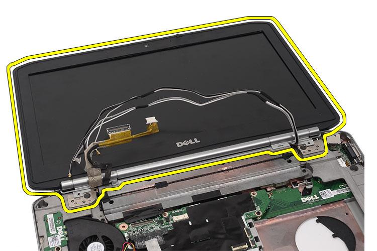
84 13. Remove the screws that secure the display assembly to the computer. 84
85 14. Remove the display assembly. 85
86 86
87 Installing the Display Assembly 1. Attach the display assembly to the base of the computer. 2. Tighten the screws to secure the display assembly. 3. Connect the low-voltage differential (LVDS) cable to the system board. 4. Connect the camera cable to the system board connector. 5. Push the antenna cables through the opening of the bottom of the computer. 6. Secure the antenna cables to the routing channels. 7. Connect the antenna cables to the WLAN/WLAN cards. 8. Replace the palm rest. 9. Replace the CPU door. 10. Replace the keyboard. 11. Replace the keyboard trim. 12. Replace the hard drive. 13. Replace the optical drive. 14. Replace the back panel. 15. Replace the battery. 16. Follow the procedures in After Working Inside Your Computer. 87
88 88
89 Brackets 23 Removing the Support Brackets 1. Follow the procedures in Before Working On Your Computer. 2. Remove the battery. 3. Remove the back panel. 4. Remove the keyboard trim. 5. Remove the keyboard. 6. Remove the optical drive. 7. Remove the CPU door. 8. Remove the palm rest. 9. Remove the display assembly. 10. Remove the screws that secure the right support bracket. 89
90 11. Remove the right support bracket. 90
91 12. Remove the screws that secure the left support bracket. 91
92 13. Remove the left support bracket. 92
93 93
94 Installing the Support Brackets 1. Place the right support bracket in the computer. 2. Tighten the screws to secure the right support bracket. 3. Place the left support bracket in the computer. 4. Tighten the screws to secure the left support bracket. 5. Replace the display assembly. 6. Replace the palm rest. 7. Replace the LED board. 8. Replace the CPU door. 9. Replace the keyboard. 10. Replace the keyboard trim. 11. Replace the optical drive. 12. Replace the back panel. 13. Replace the battery. 14. Follow the procedures in After Working Inside Your Computer. 94
95 Modem Card 24 Removing the Modem Card 1. Follow the procedures in Before Working On Your Computer. 2. Remove the battery. 3. Remove the back panel. 4. Remove the keyboard trim. 5. Remove the keyboard. 6. Remove the optical drive. 7. Remove the hard drive 8. Remove the CPU door. 9. Remove the palm rest. 10. Remove the display assembly. 11. Remove the support brackets. 12. Remove the screw that secures the modem card. 95
96 13. Lift the modem card, to disengage from the connector on the back of the card. 96
97 14. Disconnect the modem cable from the modem. 97

98 15. Remove the modem card. 98
99 99
100 Installing the Modem Card 1. Connect the modem cable. 2. Attach the connector on the back of the modem card to the connector on the I/O panel. 3. Replace the support brackets. 4. Replace the display assembly. 5. Replace the palm rest. 6. Replace the CPU door. 7. Replace the keyboard. 8. Replace the keyboard trim 9. Replace the optical drive. 10. Replace the back panel. 11. Replace the battery. 12. Follow the procedures in After Working Inside Your Computer. 100
101 Audio Board 25 Removing the Audio Board 1. Follow the procedures in Before Working On Your Computer. 2. Remove the battery. 3. Remove the back panel. 4. Remove the keyboard trim. 5. Remove the keyboard. 6. Remove the optical drive. 7. Remove the CPU door. 8. Remove the palm rest. 9. Remove the Bluetooth card. 10. Disconnect the audio board cables from the system board. 101
102 11. Remove the screw that secures the audio board to the computer. 102
103 12. Remove the audio board. 103
104 104
105 Installing the Audio Board 1. Place the audio board in the computer. 2. Tighten the screw to secure the audio board. 3. Connect the audio cables to the system board. 4. Replace the Bluetooth card. 5. Replace the palm rest. 6. Replace the CPU door. 7. Replace the keyboard. 8. Replace the keyboard trim. 9. Replace the optical drive. 10. Replace the back panel. 11. Replace the battery. 12. Follow the procedures in After Working Inside Your Computer. 105
106 106
107 System Board 26 Removing the System Board 1. Follow the procedures in Before Working On Your Computer. 2. Remove the battery. 3. Remove the subscriber identity module (SIM) card. 4. Remove the secure digital (SD) card. 5. Remove the back panel. 6. Remove the memory. 7. Remove the keyboard trim. 8. Remove the keyboard. 9. Remove the optical drive. 10. Remove the hard drive. 11. Remove the wireless local area network (WLAN). 12. Remove the wireless wide area network (WWAN). 13. Remove the CPU door. 14. Remove the heat sink: 15. Remove the processor. 16. Remove the palm rest. 17. Remove the ExpressCard/Smart Card/PCMCIA module. 18. Remove the display assembly. 19. Remove the LED board. 20. Remove the support brackets. 21. Disconnect the power connector cable. 107

108 22. Disconnect the following cables from the system board: thermal fan cable speaker cable audio board cable bluetooth cable 108

109 23. Remove the screws that secure the system board. 109
110 24. Lift the edge of the system board to disconnect it from the input/output (I/O) panel. 110
111 25. Release the system board from the port connectors. 111
112 26. Remove the system board. 112
113 Installing the System Board 1. Align the system board to the port connectors and place the system board in the computer. 2. Engage the connector on the back of the system board to the input/ output (I/O panel). 3. Tighten the screws to secure the system board. 4. Connect the following cables to the system board: 113
114 thermal fan cable speaker cable audio board cable bluetooth cable 5. Replace the support brackets. 6. Replace the LED board. 7. Replace the display assembly. 8. Replace the ExpressCard/Smart Card/PCMCIA module. 9. Replace the palm rest. 10. Replace the processor. 11. Replace the heat sink. 12. Replace the CPU door Replace the wireless wide area network (WWAN). 14. Replace the wireless local area network (WLAN). 15. Replace the hard drive. 16. Replace the optical drive. 17. Replace the keyboard. 18. Replace the keyboard trim 19. Replace the memory. 20. Replace the back panel. 21. Replace the secure digital (SD) card. 22. Replace the subscriber identity module (SIM) card. 23. Replace the battery. 24. Follow the procedures in After Working Inside Your Computer. 114
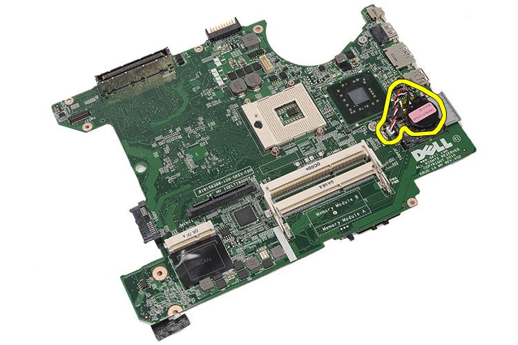
115 Coin-Cell Battery 27 Removing the Coin-Cell Battery 1. Follow the procedures in Before Working On Your Computer. 2. Remove the battery. 3. Remove the subscriber identity module (SIM) card. 4. Remove the secure digital (SD) card. 5. Remove the back panel. 6. Remove the memory. 7. Remove the keyboard trim. 8. Remove the keyboard. 9. Remove the optical drive. 10. Remove the hard drive. 11. Remove the wireless wide area network (WWAN). 12. Remove the wireless local area network (WLAN). 13. Remove the CPU door. 14. Remove the heat sink. 15. Remove the processor. 16. Remove the palm rest. 17. Remove the ExpressCard/Smart Card/PCMCIA module, 18. Remove the display assembly. 19. Remove the LED board. 20. Remove the support brackets. 21. Remove the system board. 22. Disconnect the coin-cell battery connector. 115

116 23. Pry and remove the coin-cell battery. 116
117 117
118 Installing the Coin-Cell Battery 1. Connect the coin-cell battery to system board and secure it. 2. Replace the system board. 3. Replace the support brackets. 4. Replace the LED board. 5. Replace the display assembly. 6. Replace the ExpressCard/Smart Card/PCMCIA module. 7. Replace the palm rest. 8. Replace the processor. 9. Replace the heat sink. 10. Replace the CPU door. 11. Replace the wireless local area network (WLAN). 12. Replace the wireless wide area network (WWAN). 13. Replace the hard drive. 14. Replace the optical drive. 15. Replace the keyboard. 16. Replace the keyboard trim. 17. Replace the memory. 18. Replace the back panel. 19. Replace the secure digital (SD) card. 20. Replace the subscriber identity module (SIM) card. 21. Replace the battery. 22. Follow the procedures in After Working Inside Your Computer. 118
119 Input/Output Panel 28 Removing The Input/Output (I/O) Panel 1. Follow the procedures in Before Working On Your Computer. 2. Remove the battery. 3. Remove the subscriber identity module (SIM) card. 4. Remove the secure digital (SD) card. 5. Remove the back panel. 6. Remove the memory 7. Remove the keyboard trim. 8. Remove the keyboard. 9. Remove the optical drive. 10. Remove the hard drive. 11. Remove the wireless local area network (WLAN). 12. Remove the wireless wide area network (WWAN). 13. Remove the CPU door. 14. Remove the heat sink. 15. Remove the processor. 16. Remove the palm rest. 17. Remove the ExpressCard/Smart Card/PCMCIA module. 18. Remove the display assembly. 19. Remove the LED board. 20. Remove the support brackets. 21. Remove the system board. 22. Remove the screws that secure the I/O panel. 119
120 23. Remove the I/O panel. 120
121 121
122 Installing the Input/Output (I/O) Panel 1. Place the I/O panel in the computer. 2. Tighten the screws to secure the I/O panel. 3. Replace the system board. 4. Replace the support brackets. 5. Replace the LED board. 6. Replace the display assembly. 7. Replace the ExpressCard/Smart Card/PCMCIA module 8. Replace the palm rest. 9. Replace the processor. 10. Replace the heat sink. 11. Replace the CPU door. 12. Replace the wireless local area network (WLAN). 13. Replace the wireless wide area network (WWAN). 14. Replace the hard drive. 15. Replace the optical drive. 16. Replace the keyboard. 17. Replace the keyboard trim. 18. Replace the memory. 19. Replace the back panel. 20. Replace the secure digital (SD) card. 21. Replace the subscriber identity module (SIM) card. 22. Replace the battery. 23. Follow the procedures in After Working Inside Your Computer. 122
123 Power Connector 29 Removing the Power Connector 1. Follow the procedures in Before Working On Your Computer. 2. Remove the battery. 3. Remove the subscriber identity module (SIM) card. 4. Remove the secure digital (SD) card. 5. Remove the back panel. 6. Remove the memory. 7. Remove the keyboard trim. 8. Remove the keyboard. 9. Remove the optical drive. 10. Remove the hard drive. 11. Remove the wireless local area network (WLAN). 12. Remove the wireless wide area network (WWAN). 13. Remove the CPU door. 14. Remove the heat sink. 15. Remove the processor. 16. Remove the palm rest. 17. Remove the ExpressCard/Smart Card/PCMCIA module 18. Remove the display assembly 19. Remove the LED board. 20. Remove the support brackets. 21. Remove the system board. 22. Remove the power connector from the routing channel. 123
124 23. Remove the power connector. 124
125 125
126 Installing the Power Connector 1. Secure the DC-In port to the routing channel on the processor fan. 2. Replace the system board. 3. Replace the support brackets. 4. Replace the LED board. 5. Replace the display assembly. 6. Replace the ExpressCard/Smart Card/PCMCIA module. 7. Replace the palm rest. 8. Replace the processor. 9. Replace the heat sink. 10. Replace the CPU door. 11. Replace the wireless wide area network (WWAN). 12. Replace the wireless local area network (WLAN). 13. Replace the hard drive. 14. Replace the optical drive. 15. Replace the keyboard. 16. Replace the keyboard trim. 17. Replace the memory. 18. Replace the back panel. 19. Replace the secure digital (SD) card. 20. Replace the subscriber identity module (SIM) card. 21. Replace the battery. 22. Follow the procedures in After Working Inside Your Computer. 126
127 Modem Connector 30 Removing the Modem Connector 1. Follow the procedures in Before Working On Your Computer. 2. Remove the battery. 3. Remove the subscriber identity module (SIM) card. 4. Remove the secure digital (SD) card. 5. Remove the back panel. 6. Remove the memory. 7. Remove the keyboard trim. 8. Remove the keyboard. 9. Remove the optical drive. 10. Remove the hard drive. 11. Remove the wireless local area network (WLAN). 12. Remove the wireless wide area network (WWAN). 13. Remove the CPU door. 14. Remove the heat sink. 15. Remove the processor. 16. Remove the palm rest. 17. Remove the ExpressCard/Smart Card/PCMCIA module 18. Remove the display assembly. 19. Remove the LED board. 20. Remove the modem card. 21. Remove the support brackets. 22. Remove the system board. 23. Remove the power connector. 24. Remove the modem cable from the routing channel. 127
128 25. Remove the modem connector. 128
129 129
130 Installing the Modem Connector 1. Secure the modem connector into the routing channel on the thermal fan. 2. Replace the system board. 3. Replace the support brackets. 4. Replace the audio board. 5. Replace the bluetooth. 6. Replace the audio board. 7. Replace the display assembly. 8. Replace the ExpressCard/Smart Card/PCMCIA module. 9. Replace the palm rest. 10. Replace the processor. 11. Replace the heat sink. 12. Replace the CPU door. 13. Replace the wireless local area network (WLAN) 14. Replace the wireless wide area network (WWAN) 15. Replace the hard drive. 16. Replace the optical drive. 17. Replace the keyboard. 18. Replace the keyboard trim. 19. Replace the memory. 20. Replace the back panel. 21. Replace the secure digital (SD) card. 22. Replace the subscriber identity module (SIM) card. 23. Replace the battery. 24. Follow the procedures in After Working Inside Your Computer. 130
131 Thermal Fan 31 Removing the Thermal Fan 1. Follow the procedures in Before Working On Your Computer. 2. Remove the battery. 3. Remove the subscriber identity module (SIM) card. 4. Remove the secure digital (SD) card. 5. Remove the back panel. 6. Remove the memory. 7. Remove the keyboard trim. 8. Remove the keyboard. 9. Remove the optical drive. 10. Remove the hard drive. 11. Remove the wireless local area network (WLAN). 12. Remove the wireless wide area network (WWAN). 13. Remove the CPU door. 14. Remove the heat sink. 15. Remove the processor. 16. Remove the palm rest. 17. Remove the ExpressCard/Smart Card/PCMCIA module. 18. Remove the display assembly. 19. Remove the LED board. 20. Remove the support brackets. 21. Remove the system board. 22. Disengage the power connector and the modem connector cables from the routing channel. 131

132 23. Remove the screw that secures the thermal fan. 132
133 24. Remove the thermal fan. 133
134 134
135 Installing the Thermal Fan 1. Connect the processor fan in the computer. 2. Tighten the screws to secure the processor fan. 3. Secure the power connector and the modem connector cables to the routing channels. 4. Replace the system board. 5. Replace the brackets. 6. Replace the LED board. 7. Replace the display assembly. 8. Replace the ExpressCard/Smart Card/PCMCIA module. 9. Replace the palm rest. 10. Replace the processor. 11. Replace the heat sink. 12. Replace the CPU door. 13. Replace the wireless local area network (WLAN). 14. Replace the wireless wide area network (WWAN). 15. Replace the hard drive. 16. Replace the optical drive. 17. Replace the keyboard. 18. Replace the keyboard trim. 19. Replace the memory. 20. Replace the back panel. 21. Replace the secure digital (SD) card. 22. Replace the subscriber identity module (SIM) card. 23. Replace the battery. 24. Follow the procedures in After Working Inside Your Computer. 135
136 136
137 Speaker 32 Removing the Speakers 1. Follow the procedures in Before Working On Your Computer. 2. Remove the battery. 3. Remove the subscriber identity module (SIM) card. 4. Remove the secure digital (SD) card. 5. Remove the back panel. 6. Remove the memory. 7. Remove the keyboard trim. 8. Remove the keyboard. 9. Remove the optical drive. 10. Remove the hard drive. 11. Remove the wireless local area network (WLAN). 12. Remove the wireless wide area network (WWAN). 13. Remove the CPU door. 14. Remove the heat sink. 15. Remove the processor. 16. Remove the palm rest. 17. Remove the ExpressCard/Smart Card/PCMCIA module. 18. Remove the display assembly. 19. Remove the LED board. 20. Remove the support brackets. 21. Remove the system board. 22. Remove the bluetooth card. 23. Remove the audio board. 24. Remove the screws that secure the speakers. 137
138 25. Remove the speaker cables from the routing channels. 26. Remove the speakers. 138
139 Installing the Speakers 1. Secure the speaker cables to the routing channels. 2. Connect the speakers. 3. Tighten the screws to secure the speakers. 4. Replace the audio board. 5. Replace the Bluetooth. 6. Replace the system board. 7. Replace the support brackets. 8. Replace the LED board.. 9. Replace the display assembly. 10. Replace the ExpressCard/Smart Card/PCMCIA module. 11. Replace the palm rest. 12. Replace the processor. 13. Replace the heat sink. 14. Replace the CPU door. 15. Replace the wireless local area network (WLAN). 16. Replace the wireless wide area network (WWAN). 17. Replace the hard drive. 18. Replace the optical drive. 19. Replace the keyboard. 20. Replace the keyboard trim. 21. Replace the keyboard trim and keyboard. 22. Replace the memory. 23. Replace the back panel. 24. Replace the secure digital (SD) card. 25. Replace the subscriber identity module (SIM) card. 26. Replace the battery. 27. Follow the procedures in After Working Inside Your Computer. 139
140 140
141 Display Bezel 33 Removing the Display Bezel 1. Follow the procedures in Before Working On Your Computer. 2. Remove the battery. 3. Pry up the bottom edge of the display bezel. 4. Work your way around the sides and the top edge of the display bezel. 5. Remove the display bezel. 141
142 Installing the Display Bezel 1. Place the display bezel on the computer. 2. From the top edge, press downward on the display bezel to engage the tabs om all the edges. 3. Work your way around the side and the bottom edge. 4. Replace the battery. 5. Follow the procedures in After Working Inside Your Computer. 142
 cable from the back of the display panel. 6.")
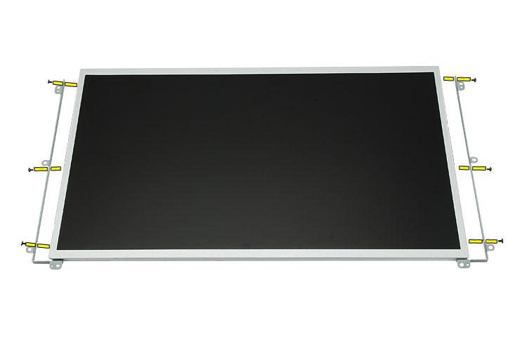
143 Display Panel 34 Removing the Display Panel 1. Follow the procedures in Before Working On Your Computer. 2. Remove the battery. 3. Remove the display bezel. 4. Remove the screws that secure the display panel. 5. Disconnect the low-voltage differential signaling (LVDS) cable from the back of the display panel. 6. Remove the display panel from the display assembly. 143

144 7. Remove the screws that secure the display brackets to the display panel and remove the brackets. 144
145 145
146 Installing the Display Panel 1. Align the display brackets with the display panel. 2. Tighten the screws to secure the display panel. 3. Connect the low-voltage differential signaling (LVDS) cable to the back of the display panel. 4. Place the display panel in the display cover. 5. Tighten the screws to secure the display panel. 6. Replace the display bezel. 7. Replace the battery. 8. Follow the procedures in After Working Inside Your Computer. 146
147 Display Hinges 35 Removing the Display Hinges 1. Follow the procedures in Before Working On Your Computer. 2. Remove the battery. 3. Remove the back panel. 4. Remove the keyboard trim. 5. Remove the keyboard. 6. Remove the optical drive. 7. Remove the CPU door. 8. Remove the palm rest. 9. Remove the display assembly. 10. Remove the display bezel Remove the display panel. 12. Remove the screws that secure the display hinges. 13. Remove the display hinges from the display assembly. 147
148 14. Separate the display hinge towers from the hinges. 15. Remove the hinge caps from the display hinges. 148
149 Installing the Display Hinges 1. Secure the display hinge caps onto the ends of the hinges. 2. Insert the display hinges into the hinge towers. 3. Insert the low-voltage differential signaling (LVDS) cable into the left hinge tower. 4. Replace the left hinge on the display cover. 5. Replace the antenna cables into the right hinge tower. 6. Replace the right hinge on the display cover. 7. Tighten the screw to secure the display hinges. 8. Replace the display panel. 9. Replace the display bezel. 10. Replace the display assembly. 11. Replace the palm rest. 12. Replace the CPU door. 13. Replace the optical drive. 14. Replace the keyboard. 15. Replace the keyboard trim. 16. Replace the back panel Replace the battery. 18. Follow the procedures in After Working Inside Your Computer. 149
150 150

151 Camera 36 Removing the Camera Module 1. Follow the procedures in Before Working On Your Computer. 2. Remove the battery. 3. Remove the display bezel. 4. Remove the display panel. 5. Disconnect the camera cable. 6. Loosen the screw that secures the camera module. 7. Lift and remove the camera module. 151
152 Installing the Camera Module 1. Place the camera module on the display cover. 2. Tighten the screw to secure the camera. 3. Connect the camera cable to the camera module. 4. Replace the display panel 5. Replace the display bezel. 6. Replace the battery. 7. Follow the procedures in After Working Inside Your Computer. 152
153 Specifications 37 Technical Specifications NOTE: Offerings may vary by region. The following specifications are only those required by law to ship with your computer. For more information regarding the configuration of your computer, click Start Help and Support and select the option to view information about your computer. System Information Chipset Latitude 5420/E5420/ 5520/E5520 Latitude E5420m/E5520m DRAM bus width Flash EPROM PCIe Gen1 bus Intel HM65 Express chipset Intel GM45 Express chipset 64-bit SPI 32 Mbits 100 MHz Processor Types Latitude 5420/E5420/ 5520/E5520 Latitude E5420m/E5520m Intel Core i3/i5/i7 series Intel Core 2 series Intel Celeron (Socket P) series Memory Memory connector Memory capacity two SODIMM slots 1 GB, 2 GB, 4 GB, or 8 GB Memory type Latitude 5420/E5420/5520/E5520 Latitude E5420m/E5520m DDR3 SDRAM, 1333 MHz DDR3 SDRAM, 1066 MHz 153
154 Memory Minimum memory Maximum memory 1 GB 8 GB NOTE: Only 64-bit operating systems support more than 4 GB memory. Audio Type Controller Stereo Conversion two-channel high definition audio 92HD90B 24-bit (analog-to-digital and digital-toanalog) Interface: Internal External Speakers Internal speaker amplifier Volume controls high definition audio microphone-in connector, stereo headphones/external speakers connector 1.5 W stereo 1.5 W mono media buttons for Media control Video Type Data bus Intel UMA video integrated video Video controller Latitude 5420/E5420/5520/E5520 Intel HD Graphics Intel HD Graphics 3000 Latitude E5420m/E5520m Output Intel GM45 15-pin video connector 19-pin HDMI connector 154
155 Communications Network adapter Wireless 10/100/1000 Mbps Ethernet LAN internal wireless local area network (WLAN), wireless wide area network (WWAN), and Bluetooth wireless support Ports and Connectors Audio Video Network adapter USB Memory card reader microphone connector, stereo headphone/ speakers connector 15-pin VGA connector RJ-45 connector three 4-pin USB 2.0-compliant connectors, one esata/usb 2.0-compliant connector 5-in-1 memory card reader Display Type White Light Emitting Diode (WLED) display Size Latitude 5420/E5420/E5420m Latitude 5520/E55420/E5520m 14.0 inch high definition WLED 15.6 inch high definition WLED Active area (X/Y) Latitude 5420/E5420/E5420m Latitude 5520/E55420/E5520m mm/ mm mm/ mm Dimensions: Height Latitude 5420/E5420/E5420m Latitude 5520/E55420/E5520m mm (7.57 inches) mm (8.27 inches) Width Latitude 5420/E5420/E5420m Latitude 5520/E55420/E5520m mm (12.75 inches) mm (14.17 inches) 155
156 Display Z-Height Latitude 5420/E5420/E5420m Latitude 5520/E55420/E5520m 5.20 mm (0.20 inch) 5.80 mm (0.23 inch) Diagonal Latitude 5420/E5420/E5420m Latitude 5520/E55420/E5520m mm (14.00 inches) mm (15.60 inches) Maximum resolution Latitude 5420/E5420/E5420m HD HD x 768 at 262 K colors 1600 x 900 at 262 K colors Latitude 5520/E55420/E5520m HD FHD Typical Brightness 1366 x 768 at 263 K colors 1920 x 1080 at 262 K colors 200 nits Operating angle 0 (closed) to 135 Refresh rate 60 Hz Minimum Viewing angles: Horizontal +40 / 40 Vertical +10 / 30 Pixel pitch Latitude 5420/E5420/E5420m HD HD mm x mm mm x mm Latitude 5520/E55420/E5520m HD FHD mm x mm mm x mm 156
157 Keyboard Number of keys United States: 86 keys, United Kingdom: 87 keys, Brazil: 87 keys, and Japan: 90 keys Layout QWERTY/AZERTY/Kanji Touchpad Active Area X-axis Y-axis mm mm Battery Type 4-, 6- or 9-cell "smart" lithium ion Dimensions: Height 4-, 6-, and 9-cell mm (0.79 inch) Width 4- and 6-cell mm (8.18 inches) 9-cell mm (8.43 inches) Depth 4- and 6-cell mm (1.89 inches) 9-cell mm (2.83 inches) Weight 4-cell 6-cell 9-cell g (0.53 lb) g (0.76 lb) g (1.12 lb) Voltage 4-cell 14.8 VDC 6- and 9-cell 11.1 VDC Temperature range: 157
158 Battery Operating Non-Operating 0 C to 50 C (32 F to 122 F) 40 C to 85 C ( 40 F to 185 F) NOTE: The battery pack is capable of safely withstanding the above storage temperatures with 100% charge. NOTE: The battery pack is also capable of withstanding storage temperatures from 20 C to +60 C with no degradation in its performance. Coin-cell battery 3 V CR2032 lithium coin cell AC Adapter Input voltage Input current (maximum) Input frequency Output power 100 VAC to 240 VAC 1.5 A, 1.6 A, or 1.7 A 50 Hz to 60 Hz 65 W or 90 W Output current 65 W 90 W 3.34 A (continuous) 4.62 A (continuous) Rated output voltage / 1.0 VDC Dimensions 65 W 90 W Height mm (0.63 inch) mm (0.63 inch) Width mm (2.60 inches) Length mm (5.00 inches) mm (2.76 inches) mm (5.79 inches) Temperature range: Operating Non-Operating 0 C to 40 C (32 F to 104 F) 40 C to 70 C ( 40 F to 158 F) 158
Dell Precision M4600 Owner's Manual
 Dell Precision M4600 Owner's Manual Regulatory Model P13F Regulatory Type P13F001 Notes, Cautions, and Warnings NOTE: A NOTE indicates important information that helps you make better use of your computer.
Dell Latitude E6220. Setup And Features Information. About Warnings. Front And Back View
 Dell Latitude E6220 Setup And Features Information About Warnings WARNING: A WARNING indicates a potential for property damage, personal injury, or death. Front And Back View Figure 1. Front View 1. microphone
Dell XPS L702X Service Manual
 Dell XPS L702X Service Manual Regulatory model: P09E series Regulatory type: P09E002 Notes, Cautions, and Warnings NOTE: A NOTE indicates important information that helps you make better use of your computer.
Dell Inspiron N5110 Service Manual
 Dell Inspiron N5110 Service Manual Regulatory model: P17F Regulatory type: P17F001 Notes, Cautions, and Warnings NOTE: A NOTE indicates important information that helps you make better use of your computer.
Dell Vostro 3350/3450/3550/3555/3750
 Dell Vostro 3350/3450/3550/3555/3750 Setup And Features Information About Warnings WARNING: A WARNING indicates a potential for property damage, personal injury, or death. Front and Back View Vostro 3350
Dell Precision M4600/M6600 Mobile Workstation
 Dell Precision M4600/M6600 Mobile Workstation Setup And Features Information About Warnings WARNING: A WARNING indicates a potential for property damage, personal injury, or death. M4600 Front And Back
Dell XPS 14z Owner s Manual
 Dell XPS 14z Owner s Manual Computer model: L412z Regulatory model: P24G series Regulatory type: P24G001 Notes, Cautions, and Warnings NOTE: A NOTE indicates important information that helps you make better
Dell Precision Mobile Workstation M4700/M6700
 Dell Precision Mobile Workstation M4700/M6700 Setup And Features Information About Warnings WARNING: A WARNING indicates a potential for property damage, personal injury, or death. M4700 Front and Back
Dell Optiplex 390. Setup And Features Information. About Warnings. Mini-Tower Front And Back View
 Dell Optiplex 390 Setup And Features Information About Warnings WARNING: A WARNING indicates a potential for property damage, personal injury, or death. Mini-Tower Front And Back View Figure 1. Front And
Dell XPS M1530 Service Manual
 Dell XPS M1530 Service Manual Model PP28L www.dell.com support.dell.com Notes, Notices, and Cautions NOTE: A NOTE indicates important information that helps you make better use of your computer. NOTICE:
Dell Studio 1569 Comprehensive Specifications
 Dell Studio 1569 Comprehensive Specifications This document provides information that you may need when setting up, updating drivers for, and upgrading your computer. NOTE: Offerings may vary by region.
Dell XPS M1730 Service Manual
 Dell XPS M1730 Service Manual Model PP06XA www.dell.com support.dell.com Notes, Notices, and Cautions NOTE: A NOTE indicates important information that helps you make better use of your computer. NOTICE:
Dell Latitude E5410/E5510
 Dell Latitude E5410/E5510 Setup and Features Information About Warnings WARNING: A WARNING indicates a potential for property damage, personal injury, or death. Latitude E5410 Front View 19 18 20 21 17
Inspiron Service Manual. 2-in-1. Computer Model: Inspiron Regulatory Model: P69G Regulatory Type: P69G001
 Inspiron 13 5000 2-in-1 Service Manual Computer Model: Inspiron 13-5378 Regulatory Model: P69G Regulatory Type: P69G001 Notes, cautions, and warnings NOTE: A NOTE indicates important information that helps
Dell Latitude Setup And Features Information. Front View. About Warnings
 Dell Latitude 3330 Setup And Features Information About Warnings WARNING: A WARNING indicates a potential for property damage, personal injury, or death. Front View Figure 1. Front View 1. microphone 2.
Dell Latitude E6430 / E6430 ATG Owner's Manual
 Dell Latitude E6430 / E6430 ATG Owner's Manual Regulatory Model: P25G Regulatory Type: P25G001, P25G002 Notes, Cautions, and Warnings NOTE: A NOTE indicates important information that helps you make better
XPS 15 2-in-1. Service Manual. Computer Model: XPS Regulatory Model: P73F Regulatory Type: P73F001
 XPS 15 2-in-1 Service Manual Computer Model: XPS 15-9575 Regulatory Model: P73F Regulatory Type: P73F001 Notes, cautions, and warnings NOTE: A NOTE indicates important information that helps you make better
Thank you for purchasing this Factory Service Manual CD/DVD from servicemanuals4u.com.
 Thank you for purchasing this Factory Service Manual CD/DVD from servicemanuals4u.com. Please check out our ebay auctions for more great deals on Factory Service Manuals: servicemanuals4u Dell Latitude
Inspiron 22. Service Manual Series. Regulatory Model: W17B Regulatory Type: W17B001
 Inspiron 22 3000 Series Service Manual Regulatory Model: W17B Regulatory Type: W17B001 Notes, cautions, and warnings NOTE: A NOTE indicates important information that helps you make better use of your
Dell OptiPlex XE2. Setup And Features Information. Mini-Tower Front and Back View. About Warnings
 Dell OptiPlex XE2 Setup And Features Information About Warnings WARNING: A WARNING indicates a potential for property damage, personal injury, or death. Mini-Tower Front and Back View Figure 1. Front and
Thank you for purchasing this Factory Service Manual CD/DVD from servicemanuals4u.com.
 Thank you for purchasing this Factory Service Manual CD/DVD from servicemanuals4u.com. Please check out our ebay auctions for more great deals on Factory Service Manuals: servicemanuals4u Dell Inspiron
Dell Latitude E5400 and E5500 Setup and Features Information
 About Warnings WARNING: A WARNING indicates a potential for property damage, personal injury, or death. Dell Latitude E5400 and E5500 Setup and Features Information E5400/E5500 With Unified Memory Architecture
Dell Precision T1700. Setup And Features Information. Mini-Tower Front and Back View. About Warnings
 Dell Precision T1700 Setup And Features Information About Warnings WARNING: A WARNING indicates a potential for property damage, personal injury, or death. Mini-Tower Front and Back View Figure 1. Front
ALIENWARE AURORA SERVICE MANUAL 01/
 ALIENWARE AURORA SERVICE MANUAL 01/ 01 Notes, Cautions, and Warnings NOTE: A NOTE indicates important information that helps you make better use of your computer. CAUTION: A CAUTION indicates either potential
Dell Inspiron XPS and Inspiron 9100 Service Manual
 Dell Inspiron XPS and Inspiron 9100 Service Manual Dell Inspiron XPS and Inspiron 9100 Service Manual Before You Begin Memory Module, Mini PCI Card, and Devices System Components Subwoofer Bluetooth Card
Dell Vostro 1014 and 1015 Setup and Features Information Tech Sheet
 About Warnings WARNING: A WARNING indicates a potential for property damage, personal injury, or death. Dell Vostro 1014 and 1015 Setup and Features Information Tech Sheet Front View 1 2 3 4 17 16 5 15
Vostro Owner's Manual
 Vostro 14-5459 Owner's Manual Regulatory Model: P68G Regulatory Type: P68G001 Copyright 2015 Dell Inc. All rights reserved. This product is protected by U.S. and international copyright and intellectual
Dell Vostro 1310/1510/1710/2510 Setup and Features Information
 9 A WARNING: A WARNING indicates a potential for property damage, personal injury, or death. Dell Vostro 1310/1510/1710/2510 Setup and Features Information Vostro 1310 1 2 3 4 5 6 13 12 10 9 8 7 11 January
Dell Latitude E5530 Owner's Manual
 Dell Latitude E5530 Owner's Manual Regulatory Model: P28G Regulatory Type: P28G001 Notes, Cautions, and Warnings NOTE: A NOTE indicates important information that helps you make better use of your computer.
Dell Vostro 5480 Owner's Manual
 Dell Vostro 5480 Owner's Manual Regulatory Model: P41G Regulatory Type: P41G002 Notes, Cautions, and Warnings NOTE: A NOTE indicates important information that helps you make better use of your computer.
Dell Latitude 14 Rugged 5414
 Dell Latitude 14 Rugged 5414 Owner's Manual Regulatory Model: P46G Regulatory Type: P46G002 Notes, cautions, and warnings NOTE: A NOTE indicates important information that helps you make better use of
Dell Latitude V710/V740 Service Manual
 Dell Latitude V710/V740 Service Manual Dell Latitude V710/V740 Service Manual Before You Begin Preparing to Work Inside the Computer Recommended Tools Computer Orientation Screw Identification System Components
Dell Precision Owner's Manual. Regulatory Model: P60F Regulatory Type: P60F001
 Dell Precision 3520 Owner's Manual Regulatory Model: P60F Regulatory Type: P60F001 Notes, cautions, and warnings NOTE: A NOTE indicates important information that helps you make better use of your product.
XPS 13 Convertible Service Manual
 XPS 13 Convertible Service Manual Computer Model: XPS 9365 Regulatory Model: P71G Regulatory Type: P71G001 Notes, cautions, and warnings NOTE: A NOTE indicates important information that helps you make
Dell Latitude Owner's Manual. Regulatory Model: P60F Regulatory Type: P60F001
 Dell Latitude 5580 Owner's Manual Regulatory Model: P60F Regulatory Type: P60F001 Notes, cautions, and warnings NOTE: A NOTE indicates important information that helps you make better use of your product.
Alienware Area-51 R5 Service Manual
 Alienware Area-51 R5 Service Manual Computer Model: Alienware Area-51 R5 Regulatory Model: D03X Regulatory Type: D03X002 Notes, cautions, and warnings NOTE: A NOTE indicates important information that
Thank you for purchasing this Factory Service Manual CD/DVD from servicemanuals4u.com.
 Thank you for purchasing this Factory Service Manual CD/DVD from servicemanuals4u.com. Please check out our ebay auctions for more great deals on Factory Service Manuals: servicemanuals4u Dell Inspiron
Dell Vostro Owner's Manual
 Dell Vostro 15 3549 Owner's Manual Regulatory Model: P45F Regulatory Type: P45F001 Notes, Cautions, and Warnings NOTE: A NOTE indicates important information that helps you make better use of your computer.
Dimensions. System information. Memory
 14 Specifications 2012 2013 Dell Inc. Dell, the DELL logo, and Inspiron are trademarks of Dell Inc. Microsoft and Windows are either trademarks or registered trademarks of Microsoft Corporation in the
ALIENWARE M11x COMPREHENSIVE SPECIFICATIONS
 ALIENWARE M11x COMPREHENSIVE SPECIFICATIONS The contents herein are subject to change without notice. 2010 Dell Inc. All rights reserved. Reproduction of these materials in any manner whatsoever without
Dell Vostro 360 Owner's Manual
 Dell Vostro 360 Owner's Manual Regulatory Model W03C Regulatory Type W03C001 Notes, Cautions, and Warnings NOTE: A NOTE indicates important information that helps you make better use of your computer.
Dell Precision M2800 Owner's Manual
 Dell Precision M2800 Owner's Manual Regulatory Model: P29F Regulatory Type: P29F001 Notes, Cautions, and Warnings NOTE: A NOTE indicates important information that helps you make better use of your computer.
Dell Edge Gateway. Service Manual Series
 Dell Edge Gateway 5000 Series Service Manual Computer Model: Dell Edge Gateway 5000/5100 Regulatory Model: N01G/N02G Regulatory Type: N01G001/N02G001 Notes, cautions, and warnings NOTE: A NOTE indicates
Dell Latitude 14 Rugged 5404 Getting Started Guide
 Dell Latitude 14 Rugged 5404 Getting Started Guide Regulatory Model: P46G Regulatory Type: P46G001 Notes, Cautions, and Warnings NOTE: A NOTE indicates important information that helps you make better
Thank you for purchasing this Factory Service Manual CD/DVD from servicemanuals4u.com.
 Thank you for purchasing this Factory Service Manual CD/DVD from servicemanuals4u.com. Please check out our ebay auctions for more great deals on Factory Service Manuals: servicemanuals4u Dell Inspiron
Inspiron Setup and Specifications
 Inspiron 14 5000 Setup and Specifications Computer Model: Inspiron 14-5468 Regulatory Model: P64G Regulatory Type: P64G006 Notes, cautions, and warnings NOTE: A NOTE indicates important information that
Dell Vostro 320 Setup and Features Information Tech Sheet
 About Warnings WARNING: A WARNING indicates a potential for property damage, personal injury, or death. Dell Vostro 320 Setup and Features Information Tech Sheet Front View 1 2 3 4 5 6 7 8 9 10 11 12 13
Dell Precision Mobile Workstation M6800 Owner's Manual
 Dell Precision Mobile Workstation M6800 Owner's Manual Regulatory Model: P30F Regulatory Type: P30F001 Copyright 2015 Dell Inc. All rights reserved. This product is protected by U.S. and international
Dell Precision Owner's Manual. Regulatory Model: P53F Regulatory Type: P53F002
 Dell Precision 7520 Owner's Manual Regulatory Model: P53F Regulatory Type: P53F002 Notes, cautions, and warnings NOTE: A NOTE indicates important information that helps you make better use of your product.
Dell OptiPlex All-in-One. Stand Installation Guide
 Dell OptiPlex All-in-One Stand Installation Guide Notes, cautions, and warnings NOTE: A NOTE indicates important information that helps you make better use of your product. CAUTION: A CAUTION indicates
Dell Vostro 460. About Warnings. Setup and Features Information
 Dell Vostro 460 Setup and Features Information About Warnings WARNING: A WARNING indicates a potential for property damage, personal injury, or death. Front and Back View 1 optical drive 2 optical drive
Dell Inspiron 300/400 Comprehensive Specifications
 Dell Inspiron 300/400 Comprehensive Specifications This document provides information that you may need when setting up, updating drivers for, and upgrading your computer. NOTE: Offerings may vary by region.
H4 Series Hardware Replacement Guide
 Machine type: 10059/7723 10060/7724 10068/7752 10080/3099/1194 10091/2558/1196 H4 Series Hardware Replacement Guide Version 3.0 2011.08 31500379 Hardware Replacement Guide Copyright Lenovo 2011. All rights
Service Manual - Memory Upgrade
 Inspiron 14 3000 Series Service Manual - Memory Upgrade Regulatory Model: P53G Regulatory Type: P53G002 Contents Before working inside your computer...3 Before you begin... 3 Safety instructions... 3 Recommended
Inspiron Setup and Specifications
 Inspiron 15 5000 Setup and Specifications Computer Model: Inspiron 5566 Regulatory Model: P51F Regulatory Type: P51F006 Notes, cautions, and warnings NOTE: A NOTE indicates important information that helps
Removing and Replacing Parts
 Removing and Replacing Parts Preparing to Work Inside the Computer Recommended Tools Screw Identification System Components Hard Drive Fixed Optical Drive Media Bay Devices Memory Modules Mini PCI Card
Dell Latitude 14 Rugged Extreme 7414 Getting Started Guide
 Dell Latitude 14 Rugged Extreme 7414 Getting Started Guide Regulatory Model: P45G Regulatory Type: P45G002 Notes, cautions, and warnings NOTE: A NOTE indicates important information that helps you make
Dell Latitude 14 Rugged Extreme (7404) Getting Started Guide
 Getting Started Guide") Dell Latitude 14 Rugged Extreme (7404) Getting Started Guide Regulatory Model: P45G Regulatory Type: P45G001 Notes, Cautions, and Warnings NOTE: A NOTE indicates important information that helps you make
Dell Latitude 14 Rugged Extreme (7404) Getting Started Guide Regulatory Model: P45G Regulatory Type: P45G001 Notes, Cautions, and Warnings NOTE: A NOTE indicates important information that helps you make
Dell Latitude 14 Rugged Extreme 7404 Owner's Manual
 Dell Latitude 14 Rugged Extreme 7404 Owner's Manual Regulatory Model: P45G Regulatory Type: P45G001 Notes, Cautions, and Warnings NOTE: A NOTE indicates important information that helps you make better
Dell Latitude E6540 Owner's Manual
 Dell Latitude E6540 Owner's Manual Regulatory Model: P29F Regulatory Type: P29F001 Notes, Cautions, and Warnings NOTE: A NOTE indicates important information that helps you make better use of your computer.
Dell Vostro Owner's Manual
 Dell Vostro 20 3052 Owner's Manual Regulatory Model: W15B Regulatory Type: W15B002 Notes, cautions, and warnings NOTE: A NOTE indicates important information that helps you make better use of your computer.
Dell Latitude Owner's Manual. Regulatory Model: P60F Regulatory Type: P60F001
 Dell Latitude 5580 Owner's Manual Regulatory Model: P60F Regulatory Type: P60F001 Notes, cautions, and warnings NOTE: A NOTE indicates important information that helps you make better use of your product.
Inspiron Setup and Specifications
 Inspiron 20 3000 Setup and Specifications Computer Model: Inspiron 20-3064 Regulatory Model: W15B Regulatory Type: W15B005 Notes, cautions, and warnings NOTE: A NOTE indicates important information that
Inspiron Setup and Specifications. Computer Model: Inspiron Regulatory Model: P66F Regulatory Type: P66F001
 Inspiron 15 5000 Setup and Specifications Computer Model: Inspiron 15-5567 Regulatory Model: P66F Regulatory Type: P66F001 Notes, cautions, and warnings NOTE: A NOTE indicates important information that
Basic Specifications INSPIRON. System Model Dell Inspiron 1545
 INSPIRON INSPIRON Basic Specifications System Model Dell Inspiron 1545 This section provides basic information that you may need when setting up, updating drivers for, and upgrading your computer. NOTE:
Inspiron Setup and Specifications
 Inspiron 15 3000 Setup and Specifications Computer Model: Inspiron 15-3565 Regulatory Model: P63F Regulatory Type: P63F003 Notes, cautions, and warnings NOTE: A NOTE indicates important information that
Dell Inspiron 660 Owner s Manual
 Dell Inspiron 660 Owner s Manual Computer model: Inspiron 660 Regulatory model: D11M Regulatory type: D11M002 Notes, Cautions, and Warnings NOTE: A NOTE indicates important information that helps you make
Dell Latitude Owner's Manual. Regulatory Model: P27S Regulatory Type: P27S001
 Dell Latitude 5280 Owner's Manual Regulatory Model: P27S Regulatory Type: P27S001 Notes, cautions, and warnings NOTE: A NOTE indicates important information that helps you make better use of your product.
Thank you for purchasing this Factory Service Manual CD/DVD from servicemanuals4u.com.
 Thank you for purchasing this Factory Service Manual CD/DVD from servicemanuals4u.com. Please check out our ebay auctions for more great deals on Factory Service Manuals: servicemanuals4u Dell Inspiron
Dell Latitude E5540 Owner's Manual
 Dell Latitude E5540 Owner's Manual Regulatory Model: P44G Regulatory Type: P44G001 Notes, Cautions, and Warnings NOTE: A NOTE indicates important information that helps you make better use of your computer.
Dell Precision Workstation T7500/T7500n Setup and Features Information
 About Warnings WARNING: A WARNING indicates a potential for property damage, personal injury, or death. Dell Precision Workstation T7500/T7500n Setup and Features Information Front and Back View 1 2 3
Inspiron Setup and Specifications
 Inspiron 24 3000 Setup and Specifications Computer Model: Inspiron 24-3464 Regulatory Model: W12C Regulatory Type: W12C006 Notes, cautions, and warnings NOTE: A NOTE indicates important information that
Dell Vostro Owner's Manual
 Dell Vostro 15 3559 Owner's Manual Regulatory Model: P52F Regulatory Type: P52F003 Notes, cautions, and warnings NOTE: A NOTE indicates important information that helps you make better use of your computer.
Dell Latitude Owner's Manual. Regulatory Model: P60F Regulatory Type: P60F001
 Dell Latitude 5580 Owner's Manual Regulatory Model: P60F Regulatory Type: P60F001 Notes, cautions, and warnings NOTE: A NOTE indicates important information that helps you make better use of your product.
Specifications 14/14R
 14/14R Specifications 2013 Dell Inc. Trademarks used in this text: Dell, the DELL logo, and Inspiron are trademarks of Dell Inc. Intel, Pentium, and Celeron are registered trademarks and Core is a trademark
Dell Latitude E5250 / 5250 Owner's Manual
 Dell Latitude E5250 / 5250 Owner's Manual Regulatory Model: P25S Regulatory Type: P25S001 Notes, Cautions, and Warnings NOTE: A NOTE indicates important information that helps you make better use of your
Dell Precision Service Manual. Regulatory Model: P74F Regulatory Type: P74F001
 Dell Precision 7530 Service Manual Regulatory Model: P74F Regulatory Type: P74F001 Notes, cautions, and warnings NOTE: A NOTE indicates important information that helps you make better use of your product.
Dell Precision M3800 Owner's Manual
 Dell Precision M3800 Owner's Manual Regulatory Model: P31F Regulatory Type: P31F001 Notes, cautions, and warnings NOTE: A NOTE indicates important information that helps you make better use of your product.
Dell Inspiron 1300 Basic Features, Affordable Widescreen DELL INSPIRON 1300 REVIEWERS GUIDE. Basic Features, Affordable Widescreen
 DELL INSPIRON 1300 REVIEWERS GUIDE Basic Features, Affordable Widescreen . YOUR CONFIGURATION Processor Intel Celeron M Processor 360 Intel Celeron M Processor 370 Intel Celeron M Processor 380 Intel Pentium
Inspiron Setup and Specifications. Computer Model: Inspiron Regulatory Model: P66F Regulatory Type: P66F001Msystems
 Inspiron 15 5000 Setup and Specifications Computer Model: Inspiron 15-5567 Regulatory Model: P66F Regulatory Type: P66F001Msystems Ltd. Notes, cautions, and warnings NOTE: A NOTE indicates important information
Dell Inspiron 580: Comprehensive Specifications
 Dell Inspiron 580: Comprehensive Specifications This document provides information that you may need when setting up, updating drivers for, and upgrading your computer. NOTE: Offerings may vary by region.
Vostro Owner's Manual. Regulatory Model: P75G Regulatory Type: P75G001
 Vostro 14-5468 Owner's Manual Regulatory Model: P75G Regulatory Type: P75G001 2016 2018 Dell Inc. or its subsidiaries. All rights reserved. Dell, EMC, and other trademarks are trademarks of Dell Inc. or
Inspiron Gaming Setup and Specifications
 Inspiron 15 5000 Gaming Setup and Specifications Computer Model: Inspiron 15-5577 Regulatory Model: P57F Regulatory Type: P57F003 Notes, cautions, and warnings NOTE: A NOTE indicates important information
Dell Latitude 14 Rugged Extreme (7404) Getting Started Guide
 Getting Started Guide") Dell Latitude 14 Rugged Extreme (7404) Getting Started Guide Regulatory Model: P45G Regulatory Type: P45G001 Notes, Cautions, and Warnings NOTE: A NOTE indicates important information that helps you make
Dell Latitude 14 Rugged Extreme (7404) Getting Started Guide Regulatory Model: P45G Regulatory Type: P45G001 Notes, Cautions, and Warnings NOTE: A NOTE indicates important information that helps you make
Dell Latitude C800 SERVICE MANUAL. support.dell.com
 Dell Latitude C800 SERVICE MANUAL www.dell.com support.dell.com Dell Latitude C800 SERVICE MANUAL www.dell.com support.dell.com Notes, Notices, and Cautions NOTE: A NOTE indicates important information
Dell Latitude XT3 Owner's Manual
 Dell Latitude XT3 Owner's Manual Regulatory Model P17G Regulatory Type P17G001 Notes, Cautions, and Warnings NOTE: A NOTE indicates important information that helps you make better use of your computer.
Dimensions. System Information. Memory. Stand mm (19.4 inches) mm (26.1 inches) Depth mm (1.4 inches) 78.2 mm (3.
 mm (26.1 inches) Depth mm (1.4 inches) 78.2 mm (3.") 27 Specifications 2013 Dell Inc. Trademarks used in this text: Dell, the DELL logo, and XPS are trademarks of Dell Inc. Intel is a registered trademark and Core is a trademark of Intel Corporation in the
27 Specifications 2013 Dell Inc. Trademarks used in this text: Dell, the DELL logo, and XPS are trademarks of Dell Inc. Intel is a registered trademark and Core is a trademark of Intel Corporation in the
Dell E-Port Plus User s Guide
 Dell E-Port Plus User s Guide Model PRO2X www.dell.com support.dell.com Notes, Notices, and Cautions NOTE: A NOTE indicates important information that helps you make better use of your computer. NOTICE:
To connect the AC adapter:
 Replacing the AC Adapter Replacing the AC Adapter 3 Plug the power cord into a wall outlet. The power indicator turns on. To connect the AC adapter: Connect the power cord to the AC adapter. Power indicator
Dell Latitude C800 Service Manual
 Dell Latitude C800 Service Manual Dell Latitude C800 Service Manual Before You Begin Preparing to Work Inside the Computer Recommended Tools Screw Identification Removing and Replacing Parts System Components
Dell Precision Owner's Manual. Regulatory Model: P60F Regulatory Type: P60F001
 Dell Precision 3520 Owner's Manual Regulatory Model: P60F Regulatory Type: P60F001 Notes, cautions, and warnings NOTE: A NOTE indicates important information that helps you make better use of your product.
Dell Vostro 3252 Owner's Manual
 Dell Vostro 3252 Owner's Manual Regulatory Model: D14S Regulatory Type: D14S001 Notes, cautions, and warnings NOTE: A NOTE indicates important information that helps you make better use of your computer.
Latitude Owner's Manual. Regulatory Model: P72G Regulatory Type: P72G003
 Latitude 5495 Owner's Manual Regulatory Model: P72G Regulatory Type: P72G003 Notes, cautions, and warnings NOTE: A NOTE indicates important information that helps you make better use of your product. CAUTION:
Inspiron Setup and Specifications
 Inspiron 22 3000 Setup and Specifications Computer Model: Inspiron 22-3264 Regulatory Model: W17B Regulatory Type: W17B003 Notes, cautions, and warnings NOTE: A NOTE indicates important information that
Inspiron Setup and Specifications
 Inspiron 24 5000 Setup and Specifications Computer Model: Inspiron 24-5488 Regulatory Model: W12C Regulatory Type: W12C007 Notes, cautions, and warnings NOTE: A NOTE indicates important information that
Inspiron Setup and Specifications
 Inspiron 15 3000 Setup and Specifications Computer Model: Inspiron 15-3568 Regulatory Model: P47F Regulatory Type: P47F004 Notes, cautions, and warnings NOTE: A NOTE indicates important information that
XPS 15 Setup and Specifications
 XPS 15 Setup and Specifications Computer Model: XPS 15-9560 Regulatory Model: P56G Regulatory Type: P56F001 Notes, cautions, and warnings NOTE: A NOTE indicates important information that helps you make
Inspiron 13. Setup and Specifications Series 2-in-1. Computer Model: Inspiron Regulatory Model: P69G Regulatory Type: P69G001
 Inspiron 13 7000 Series 2-in-1 Setup and Specifications Computer Model: Inspiron 13-7368 Regulatory Model: P69G Regulatory Type: P69G001 Notes, cautions, and warnings NOTE: A NOTE indicates important information
XPS 27 Setup and Specifications
 XPS 27 Setup and Specifications Computer Model: XPS 7760 Regulatory Model: W13C Regulatory Type: W13C001 Notes, cautions, and warnings NOTE: A NOTE indicates important information that helps you make better
Inspiron Series. Views. Specifications
 Inspiron 15 5000 Series Views Copyright 2014 Dell Inc. All rights reserved. This product is protected by U.S. and international copyright and intellectual property laws. Dell and the Dell logo are trademarks