Model based testing and Hardware-in-the-Loop simulation of embedded CANopen control devices
|
|
|
- Cecilia Hood
- 5 years ago
- Views:
Transcription
1 Model based testing and Hardware-in-the-Loop simulation of embedded CANopen control devices Mirko Tischer; Dietmar Widmann, Vector Informatik GmbH CANopen is mainly used in connecting devices in embedded networks. During the development process of the ECU (electronic control unit), the maturity of the embedded system increases with testing in early stages. A good approach is to test before the first prototype is available. Step by step, the test environment is expanded and is able to simulate CANopen bus communication behavior. Application behavior is also added to the test environment. This paper shows the methods available at different development stages and their application. Starting with a simple network simulation that just integrates EDS files, a test environment grows as the development advances. Application behavior is added by hand-written C modules, libraries or even MATLAB/Simulink models. Finally, the simulated ECU and finished ECU use the same application code. To obtain a complete Hardware-in-the-Loop simulator, additional hardware is required to simulate sensors and actors. Testing is possible in parallel to every development step. Test procedures may range from simple interactive elements to a fully automated test system. Introduction Today, ECUs exhibit a high software content and place stringent requirements on the tests to be performed (large share of software functionality contrasts with stable complexity in the HW environment, which results in more testing effort in functional tests). Increasingly shorter development cycles practically force product manufacturers to reduce testing effort to a reasonable level, but without unacceptable level of risk to test quality. Verification and validation are playing an increasingly larger role in the overall development process. Given this situation, it appears necessary not only to proceed more efficiently in these areas, but to significantly shift testing forward in time in development phases. The advantages are obvious: de viations in the functionality are detected early on and can therefore also be corrected earlier. With consistent implementation, this leads to more stable ECU implementations and consequently also to a higher maturity level of the end product. How does model-based testing contribute to better product quality? Model-based testing is understood as a technology in which testcases can be derived from a model. After their execution, these testcases can also be automatically evaluated and documented. In all cases, the user must work with a model and follow a systematic and explicit working method in testing
2 Figure 1: Overview model-based testing For model-based testing (MBT), we need at least the following: Requirements / specification Requirements describe the system and are absolutely necessary to construct a model. A model based on these requirements The actual creative step in this process is implementation of requirements in a model, which requires enormous effort. In the further course of development, the actual software for the ECU is derived from a system model (generated or in part manually implemented). Actually, the necessary test sequences can be derived from the system model. However, This simulation may sometimes assume great complexity in simulating the relevant hardware (sensors to permit testing of the system model as well, a separate test model can also be developed from which test sequences are then derived. Testcases and test oracle The testcases and the related tests scripts can then be generated, for the most part, from the model. In this process, the test oracle establishes the expected test result. Test execution environment To enable execution of the tests scripts, a runtime environment must be provided. Naturally, this also includes a simulation of the CANopen ECU s environment. and actuators), physical environment conditions and possibly even communication with other ECUs
3 Just providing these components requires a substantial amount of effort. For these efforts, the user is rewarded with shorter test execution times (due to automated execution), an environment model (as part of the test execution environment) and the ability to flexibly react to different testing focal points. Where does the model for a CANopen ECU come from? It is easy to represent a CANopen ECU in a model using the components shown in Figure 2 <CANopen device model>. Unfortunately, the meaningfulness of this model is still very low, because it lacks the details needed to describe at least minimal application functionality. A model has the task of describing the behavior of the modeled system and is always kept simpler than the modeled system but not too simple. Figure 2: Device model CANopen The left part of the figure (communication over CANopen and the object dictionary) is already modeled to a great extent by the underlying specifications (requirements specification and model are simultaneously covered by the DS301 or DS4xx specification here). Unfortunately, this modeling is insufficient to execute a complete generation of a CANopen layer. Formal descriptions can certainly also be found in specifications by CiA, e.g. via finite state machines (FSM) and message sequence charts. However, they do not describe the comprehensive interrelationships between all individual aspects, and so these interrelationships are also lacking in a generation. It is especially difficult to form the model for the communication portion using the many optional components of CANopen. It is often unclear when an optional property should or should not be used. The question is whether it is worthwhile to create a detailed model of the communication portion of a CANopen ECU that en ables full generation of ECU code. This is doubtful, because the specification, as noted, permits too many formal gaps. A code generation from the model (here: system model) would therefore be associated with much effort, and in most cases it is not economically justifiable. It would be different if the requirements for functional safety of the CANopen ECU would require
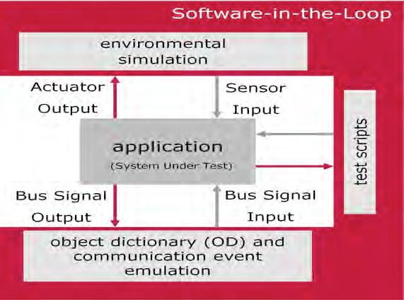
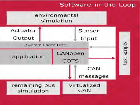
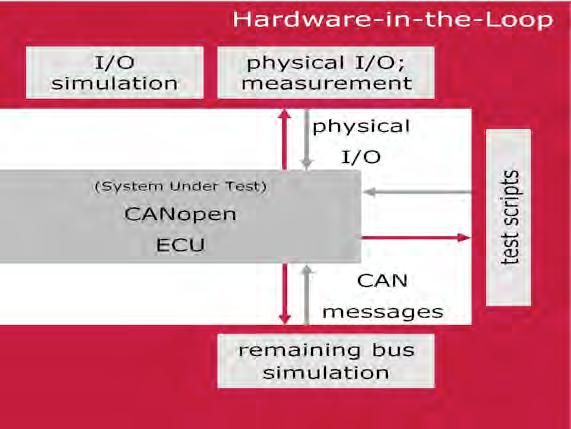
4 the use of formal methods. In general, however, CANopen communication is handled by commercially available software components, which users link to their applications as a library. Then the model (here: test model) for the communication portion of a CANopen ECU only needs to be detailed enough to permit generation of the necessary testcases. In practice, it has been demonstrated that a statically preconfigured model is entirely sufficient to generate the related tests and simulation. The user only needs to input parameters in the model (number of PDOs and layout of the object dictionary, etc.). For the application portion of the CANopen ECU, the work process also begins with requirements in a specification, and the relevant models are constructed from this information. Actually, this is ALWAYS a manual process that requires tremendous know-how. At any rate, each individual requirement must be evaluated and find a place in the model. Often, this activity is already part of the software development process for the relevant ECU, and the resulting models can also be used to create the test sequences. Model-in-the-Loop (MiL): The model (system model, executable specification) is subjected to a test. That is, input vectors are automatically changed, and observations are made of whether the output vectors remain within an expected range. Many modeling environments today already offer the capability of executing tests on this level. Software-in-the-Loop (SiL): On this integration level, the implemented algorithms can be tested on the code level. The code of the individual software components is executed on the simulation platform. Often, it is a mixture of generated code, hand-written code and driver or function libraries. Processor-in-the-Loop (PiL): The code is now executed on the target processor or on an instruction set simulator. The system environment is often still simulated on this integration level as well. Hardware-in-the-Loop (HiL): The transition from Processor-in-the- Loop Integration is fluid. Now the physical environment is also represented via real digital I/O or PWM (pulse width modulation) signals. Integration levels and execution environment As the integration level (model, component, software, ECU) changes during development, the requirements for the individual test execution environment also change. The following integration levels are distinguished here: 06-22
5 06-23
6 Figures 3 through 5 Integration levels (indicates requirements for the test adapter) To efficiently conduct tests on the given level, a very flexible test execution environment must be provided. The following aspects present a special challenge: The test sequences used on the specific integration levels should be reusable. Therefore, the test sequences must be convertible, or suitable interfaces must be available for bypassing the different levels. It must be possible to adapt test sequences to a wide variety of test adapters. Here, it makes sense to support multiple programming languages, so that adjustments can be made flexibly and costeffectively by means of interface changes. To attain reproducible results, it must be possible to automate all test sequences. The execution environment must lend itself to a high level of configurability by parameters. The ability to generate the entire environment or parts of the environment is a good idea. Architecture of the test execution environment for CANopen development As can already be seen from the device model (Figure 2), in a CANopen ECU the application and communication portion (with process data objects (PDO) and service data objects (SDO)) are loosely interrelated via the object dictionary. Therefore, it is possible for the developer to begin with the design and implementation of the application portion without having to deal with CANopen in detail. However, the following points must be considered so that the execution environment can be used relatively simply on the SiL and HiL integration levels: The NMT state information of the communication layer should be evaluated. Even if this aspect does not entirely or clearly originate from CANopen specifications, it is still necessary to have an application react appropriately to changes in the communication state. This makes it possible to couple the finite state machines (FSM) to one another. Access to all application parameters that are located in the object dictionary should be encapsulated so that these parameters can be easily simulated. All accesses to hardware should be simulated via a hardware abstraction layer (HAL)
7 Figure 6: Extended CANopen device model This implicitly extends the device model by adding the interfaces shown in Figure 6 (CAN driver; CANopen COTS component; HAL adapter; object dictionary (OD) mapper; application). As a result, the application can now be executed as a SiL on a simulation platform (under Microsoft Windows on a PC), and functional tests can be executed. The test execution environment even accepts models created with MATLAB/Simulink. Often, however, the application software is created as a library (dynamic link library; DLL) and is added to the test execution environment via the provided interfaces (application programming interface for the C language; C-API). Then the simulation environment includes full CANopen functionality, which can also cover a rest-of-bus simulation (network of multiple ECUs) and an abstraction of the physical environment. The adaptation layers (adapters) indicate changes to the relevant parameters, and the application uses the related values. Figure 7 (Sample code): Event function for pressure change and polling of an environment variable
8 The application can now be completed, step by step, by adding other components that contain additional algorithms and control sequences, and a simple integration in the test execution environment is possible at each step. The CANopen functionality of the simulation environment must be adapted to the specific requirements of the ECU under development. For this purpose, a configuration tool is used that can also process formats defined for CANopen. This always begins with an electronic description of the CANopen ECU by an electronic data sheet (EDS). This yields a configuration of CANopen communication in device configuration format (DCF). The layout of the object dictionary and configuration of the PDOs can be seen in this configuration. This information is used to generate the interfaces needed to interface to the application components under development. Once the application has been prepared to this stage, the next step is to link the CANopen protocol stack. This is commercial-off-the-shelf (COTS) software, which already implements a whole series of CANopen services. To also integrate these components into a SiL configuration within the test execution environment, it is of course important to encapsulate all accesses to the object dictionary, hardware accesses and access to CAN messages via interfaces (refer to Figures 3-5; CAN driver; HAL adapter; object dictionary (OD) mapper). The application and CANopen components are combined into a library and are inserted in the test execution environment via the provided interfaces. The CANopen simulation must now be adapted accordingly, and it now only contains any rest-of-bus simulation. This adaptation is made with tool support, and the tool regenerates relevant interfaces. Once the hardware for the CANopen ECU is available, the software is integrated which consists of the application and CANopen services. Naturally, the test execution environment must also be adapted to the required degree. The previously simulated physical environment is now made available via real hardware. The tests to be executed now run in a HiL configuration and also make it possible to simulate aspects with real-time relevance. What else does the test execution environment give us? In principle, all paths for ECU testing merge together here. In addition to the environment simulation, other aspects of primary significance are test execution control and the representation of test results. While the tester can activate and start the available test sequences in test flow control, results representation ensures that test results (output as XML and HTML) are shown in a well organized and easy to understand way. In addition, all details of a test run are recorded in log files including the bus communication. How are the tests specified? Along with semi-automated sequences (where interaction with the user is necessary during the test run, e.g. to input values), which are supported by special configurable dialogs, another capability of primary interest here is the specification of fully automated test sequences. To offer strong support for reusability, test sequences are organized into test modules. These test modules may exist in different formats, where these formats only differ in their syntax. The structure of the test modules is always uniform. The test execution environment supports efficient creation of tests by a whole series of Help functions (test service library), which permit generation of signal waveforms 06-26
9 (via stimuli functions) or simple access to CAN messages. For maximum flexibility in creating test sequences, C# (.NET) is directly supported in addition to a manufacturer-specific C-like language. There is also the option of specifying very simple test primitives via XML files. Here, the XML file represents a pattern that is provided with test data and can be executed directly within a test module. The advantage of this approach is obvious, but it is also possible to create the test specification directly in a human-readable format by means of a suitable XSLT transformation. Figure 8 (sample code) CAPL vs. XML The test modules themselves can be written by hand or be generated with suitable generators. Authoring tools are also available, which support creation of the modules (filling out of XML patterns; generation of C# modules from graphic representations). Summary This paper shows the different aspects of model-based testing based on the example of a CANopen ECU. The primary focus here is on creating the simulation environment, because this is the area where enormous efforts must always be anticipated. It was shown that a suitable architecture of the test execution environment enables reuse of test sequences and components of the simulation for different integration levels

10 Figure 9: Test Execution Environment CANoe Sources: Peter Liggesmeyer: Software-Qualität - Testen, Analysieren und Verifizieren von Software (2. Aufl.). Spektrum Akademischer Verlag 2009 Kai Schmidt, Vector Informatik GmbH: CANopen tests automatically generated,proceedings ICC2008 Mirko Tischer Vector Informatik GmbH Prototyping and testing CANopen systems Ingersheimer Str. 24 DE Stuttgart Tel: fax: mirko.tischer@vector.com
Test requirements in networked systems
 Test requirements in networked systems Jürgen Klüser, Vector Informatik GmbH The use of CAN with J1939 or CANopen based higher layers leads to cost efficient and flexible solutions, but together with a
Reuse of Hardware Independent Test Sequences across MiL-, SiL- and HiL-Test Scenarios
 Reuse of Hardware Independent Test Sequences across MiL-, SiL- and HiL-Test Scenarios Testing Expo 2008 Stuttgart Berner & Mattner Systemtechnik GmbH Contents Test methods in the automotive industry Problems
VT System Smart HIL Testing
 VT System Smart HIL Testing V1.0 2010-06-04 Agenda > ECU Testing Testing a Door Control Unit Summary and Outlook Slide: 2 ECU Testing I/O Access for ECU Testing ECU has to be tested in its natural environment
From Signal to Service
 From Signal to Service Challenges for the Development of AUTOSAR Adaptive Applications Automotive Ethernet and AUTOSAR Adaptive are key technologies for highly automated driving and comprehensive connectivity
Testing Under Time Pressure. Versatile Test Benches for Avionic Systems
 Testing Under Time Pressure Versatile Test Benches for Avionic Systems In the future, test benches will be made up from subsystems that are manufactured by specialized suppliers. It is very important to
Volvo Car Group Jonn Lantz Agile by Models
 Volvo Car Group Jonn Lantz Agile by Models Challenge Scaling agile model driven development of AUTOSAR embedded software. Lift the abstraction level of in-house development. Create reliable, automated
Decoupling Test Cases from Real and Virtual Test Systems with ASAM HIL API
 Decoupling Test Cases from Real and Virtual Test Systems with ASAM HIL API Dr. Rainer Rasche, dspace GmbH Dr. Dietmar Neumerkel, Daimler AG Workshop der ASIM/GI-Fachgruppen Simulation technischer Systeme
Automated CanOpen PDO mapping of IEC Directly Represented Variables
 Automated CanOpen PDO mapping of IEC 61131-3 Directly Represented Variables Edouard Tisserant, Laurent Bessard and Grégory Trélat, Lolitech CiA DS-405 defines a way to publish variables of IEC 61131-3
Concept Manual vteststudio. Version 2.2 English
 Concept Manual vteststudio Version 2.2 English Imprint Vector Informatik GmbH Ingersheimer Straße 24 D-70499 Stuttgart The information and data given in this user manual can be changed without prior notice.
Virtual Hardware ECU How to Significantly Increase Your Testing Throughput!
 Virtual Hardware ECU How to Significantly Increase Your Testing Throughput! Elektrobit Tech Day Jason Niatas Synopsys Inc. July 27, 2017 2017 Synopsys, Inc. 1 Agenda Automotive electronic evolution and
Rapid prototyping for CANopen system development
 Rapid prototyping for CANopen system development Heinz-Jürgen Oertel, Rüdiger Härtel, Torsten Gedenk port GmbH The development of simple CANopen devices up to complex systems requires exact planning and
Virtualizing the TCU of BMW's 8 speed transmission
 10th Symposium on Automotive Powertrain Control Systems, 11. - 12. September 2014, Berlin Virtualizing the TCU of BMW's 8 speed transmission Rui Gaspar, Benno Wiesner, Gunther Bauer Abstract Virtualization
A number of optimizations are already in use by the majority of companies in industry, notably:
 1 Abstract Mechatronics products contain significant amounts of software. Most advances in embedded software development focus on specific phases of the development process. However, very little emphasis
Guido Sandmann MathWorks GmbH. Michael Seibt Mentor Graphics GmbH ABSTRACT INTRODUCTION - WORKFLOW OVERVIEW
 2012-01-0962 AUTOSAR-Compliant Development Workflows: From Architecture to Implementation Tool Interoperability for Round-Trip Engineering and Verification & Validation Copyright 2012 The MathWorks, Inc.
Entwicklung zuverlässiger Software-Systeme, Stuttgart 30.Juni 2011
 Entwicklung zuverlässiger Software-Systeme, Stuttgart 30.Juni 2011 Tools and Methods for Validation and Verification as requested by ISO26262 1 Introduction ISO26262 ISO 26262 is the adaptation of IEC
A Model-Based Reference Workflow for the Development of Safety-Related Software
 A Model-Based Reference Workflow for the Development of Safety-Related Software 2010-01-2338 Published 10/19/2010 Michael Beine dspace GmbH Dirk Fleischer dspace Inc. Copyright 2010 SAE International ABSTRACT
Product Information CANdelaStudio
 Table of Contents 1 Introduction... 3 1.1 Properties Overview... 3 2 Functions... 4 3 ODX Functions... 7 4 Quality Improvement by Single Source Principle... 7 5 Data Exchange... 8 6 Editions... 8 6.1 CANdelaStudio
DEVELOPMENT OF DISTRIBUTED AUTOMOTIVE SOFTWARE The DaVinci Methodology
 DEVELOPMENT OF DISTRIBUTED AUTOMOTIVE SOFTWARE The DaVinci Methodology Dr. Uwe Honekamp, Matthias Wernicke Vector Informatik GmbH, Dep. PND - Tools for Networks and distributed Systems Abstract: The software
CANoe.J1939. Product Information
 Product Information Table of Contents 1 Introduction... 3 1.1 Application Areas... 3 1.2 Features and Advantages... 3 1.3 Further Information... 3 2 Functions... 4 3 Hardware Interfaces... 4 4 Transport
 Virtual ECUs for Developing Automotive Transmission Software Dr. Thomas Liebezeit 1, Jakob Bräuer 1, Roland Serway 1, Dr. Andreas Junghanns 2 1 IAV GmbH, Carnotstraße 1, 10587 Berlin 2 QTronic GmbH, Alt-Moabit
Fending Off Cyber Attacks Hardening ECUs by Fuzz Testing
 Fending Off Cyber Attacks Hardening ECUs by Fuzz Testing In designing vehicle communication networks, security test procedures play an important role in the development process. Fuzz testing, which originated
Variants and Traceability as the Challenge
 Variants and Traceability as the Challenge Model-Based Test Design as an Answer V1.0 2016-11-12 Motivation We are talking about automated ECU testing: Module tests, sub system tests, MIL, SIL, HIL Challenges
elektronik Security for Software and IT ECU ENERGY STORAGE TESTING COVER STORY Gasoline Direct Injection in-the-loop
 www.atzonline.com 03 May 2015 Volume 10 elektronik W O R L D W I D E COVER STORY Security for Software and IT ECU Gasoline Direct Injection in-the-loop TESTING Tablets in Mobile Measurement Technique ENERGY
CANopen Maritime A New Standard for Highly Dependable Communication Systems
 CANopen Maritime A New Standard for Highly Dependable Communication Systems Prof. Dr. K. Etschberger, IXXAT Automation Dipl.-Ing. C. Schlegel, IXXAT Automation Dr. O. Schnelle, MTU Friedrichshafen Bjørnar
Flash Bootloader. Product Information
 Product Information Table of Contents 1 Flash Memory Programming... 3 2 Flash Bootloader - ECU programming via CAN, LIN, FlexRay, MOST and Ethernet... 3 2.1 Overview of Advantages... 3 2.2 Application
Performing J Compliance Test with CANoe Version Application Note AN-ION
 Version 1.0 2012-01-23 Author(s) Restrictions Abstract Michalski, Jens Public This Application Note describes the method for performing a J1939-82 Compliance Test with CANoe. It covers test preparation,
Solutions for. Avionics Networking. CANoe.CANaero. CANalyzer.CANaero ENGLISH
 Solutions for Avionics Networking CANoe.CANaero ENGLISH CANalyzer.CANaero CANalyzer.CANaero 7.6 Universal Analysis Tool for CAN-based Avionics Networks Overview of Advantages Easy observation of data traffic
An Automated Testing Environment to support Operational Profiles of Software Intensive Systems
 An Automated Testing Environment to support Operational Profiles of Software Intensive Systems Abstract: Robert S. Oshana Raytheon Systems Company oshana@raytheon.com (972)344-783 Raytheon Systems Company
The Bizarre Truth! Automating the Automation. Complicated & Confusing taxonomy of Model Based Testing approach A CONFORMIQ WHITEPAPER
 The Bizarre Truth! Complicated & Confusing taxonomy of Model Based Testing approach A CONFORMIQ WHITEPAPER By Kimmo Nupponen 1 TABLE OF CONTENTS 1. The context Introduction 2. The approach Know the difference
Indigo. Vector Diagnostic Tester V / 6
 Indigo Vector Diagnostic Tester 1 / 6 V1.3 2018-09-13 Agenda 1. Indigo in General 2. Diagnostic Use Cases 3. Automation of Diagnostic Sequences 4. Remote Diagnostics 5. Summary 2 Indigo in General Executive
Cover Page. The handle holds various files of this Leiden University dissertation
 Cover Page The handle http://hdl.handle.net/1887/22891 holds various files of this Leiden University dissertation Author: Gouw, Stijn de Title: Combining monitoring with run-time assertion checking Issue
Impact of Platform Abstractions on the Development Workflow
 Impact of Platform Abstractions on the Development Workflow Johannes Pletzer, Wolfgang Pree Technical Report September 7, 2009 C. Doppler Laboratory Embedded Software Systems University of Salzburg Austria
time now it has also been used productively in a multi-oem, requires precise knowledge of the protocol, the layout, the
 ODX in Practice Experiences, challenges and potential The diagnostic exchange format ODX has been implemented successfully in a number of pilot projects. For the first time now it has also been used productively
Tools for CAN based networking. On the street, in the air, in the orbit
 Tools for CAN based networking On the street, in the air, in the orbit Vector Informatik GmbH Vector provides OEMs and suppliers of automotive and related industries a professional and open development
ISO Compliant Automatic Requirements-Based Testing for TargetLink
 ISO 26262 Compliant Automatic Requirements-Based Testing for TargetLink Dr. Udo Brockmeyer CEO BTC Embedded Systems AG An der Schmiede 4, 26135 Oldenburg, Germany udo.brockmeyer@btc-es.de Adrian Valea
POWERLINK. For CODESYS. POWERLINK For CODESYS. Integration package of the standard Industrial Ethernet protocol POWERLINK into CODESYS.
 For CODESYS For CODESYS Integration package of the standard Industrial Ethernet protocol into CODESYS. For CODESYS Two standard technologies brought together 2 About is one of the most used real-time Ethernet
V&V: Model-based testing
 V&V: Model-based testing Systems Engineering BSc Course Budapest University of Technology and Economics Department of Measurement and Information Systems Traceability Platform-based systems design Verification
Virtual Validation of Cyber Physical Systems
 Virtual Validation of Cyber Physical Systems Patrik Feth, Thomas Bauer, Thomas Kuhn Fraunhofer IESE Fraunhofer-Platz 1 67663 Kaiserslautern {patrik.feth, thomas.bauer, thomas.kuhn}@iese.fraunhofer.de Abstract:
An Integrated Test Framework to Reduce Embedded Software Lifecycle Costs
 White Paper An Integrated Test Framework to Reduce Embedded Software Lifecycle Costs Version 1.0: August 23, 2012 Presented by: Chris Domin, Business Dev. Mgr. Engineering Services, sales@danlawinc.com
Verification, Validation, and Test with Model-Based Design
 2008-01-2709 Verification, Validation, and Test with Model-Based Design Copyright 2008 The MathWorks, Inc Tom Erkkinen The MathWorks, Inc. Mirko Conrad The MathWorks, Inc. ABSTRACT Model-Based Design with
Real-Time Hardware-In-Loop simulation for automated validation of diagnostic services
 Speakers Information- Controls, Measurement & Calibration Congress Real-Time Hardware-In-Loop simulation for automated validation of diagnostic services Charu Garg, Amit Kumar, Ajay Kumar Vashisth ABSTRACT
challenges in domain-specific modeling raphaël mannadiar august 27, 2009
 challenges in domain-specific modeling raphaël mannadiar august 27, 2009 raphaël mannadiar challenges in domain-specific modeling 1/59 outline 1 introduction 2 approaches 3 debugging and simulation 4 differencing
AUTOSAR Method. Webinar
 AUTOSAR Method Webinar 2013-04-17 V2.1 2013-04-16 Agenda >Introduction AUTOSAR Method Exchange Formats Workflows OEM-TIER1 Workflows TIER1 Webinar Series Slide: 2 Introduction Current Workflow (non-autosar)
CS SOFTWARE ENGINEERING QUESTION BANK SIXTEEN MARKS
 DEPARTMENT OF COMPUTER SCIENCE AND ENGINEERING CS 6403 - SOFTWARE ENGINEERING QUESTION BANK SIXTEEN MARKS 1. Explain iterative waterfall and spiral model for software life cycle and various activities
SOLUTIONS FOR TESTING CAMERA-BASED ADVANCED DRIVER ASSISTANCE SYSTEMS SOLUTIONS FOR VIRTUAL TEST DRIVING
 SOLUTIONS FOR TESTING CAMERA-BASED ADVANCED DRIVER ASSISTANCE SYSTEMS SOLUTIONS FOR VIRTUAL TEST DRIVING Table of Contents Motivation... 3 Requirements... 3 Solutions at a Glance... 4 Video Data Stream...
Component-based Architecture Buy, don t build Fred Broks
 Component-based Architecture Buy, don t build Fred Broks 1. Why use components?... 2 2. What are software components?... 3 3. Component-based Systems: A Reality!! [SEI reference]... 4 4. Major elements
SOFTWARE ENGINEERING. To discuss several different ways to implement software reuse. To describe the development of software product lines.
 SOFTWARE ENGINEERING DESIGN WITH COMPONENTS Design with reuse designs and develops a system from reusable software. Reusing software allows achieving better products at low cost and time. LEARNING OBJECTIVES
Reasons for System Simulation with CANoe J1939 Version /06/04 Application Note AN-ION
 Version 1.1 04/06/04 Application Note AN-ION-1-3400 Author(s) Restrictions Abstract Jürgen Klüser None This Application Note discusses advantages of Communication System Modelling and Simulation by using
Minsoo Ryu. College of Information and Communications Hanyang University.
 Software Reuse and Component-Based Software Engineering Minsoo Ryu College of Information and Communications Hanyang University msryu@hanyang.ac.kr Software Reuse Contents Components CBSE (Component-Based
Operating Manual. Inferface. CANopen. English
 Operating Manual Inferface CANopen English Disclaimer The information in this brochure corresponds to our current state of knowledge. However, it is not to be understood as a warranty for certain characteristics
CANoe 6.0. The Professional Development and Test Tool for CAN, LIN, MOST, FlexRay and J1587 TOOLS FOR NETWORKS AND DISTRIBUTED SYSTEMS
 CANoe 6.0 The Professional Development and Test Tool for CAN, LIN, MOST, FlexRay and J1587 CANoe is an all-round tool for the development, testing and analysis of networks and ECUs. It supports the user
LabVIEW FPGA in Hardware-in-the-Loop Simulation Applications
 LabVIEW FPGA in Hardware-in-the-Loop Simulation Applications Publish Date: Dec 29, 2008 38 Ratings 4.16 out of 5 Overview Hardware-in-the-loop (HIL) simulation is achieving a highly realistic simulation
Release Notes. PREEvision. Version 6.5 SP13 English
 Release Notes PREEvision Version 6.5 SP13 English Imprint Vector Informatik GmbH Ingersheimer Straße 24 70499 Stuttgart, Germany Vector reserves the right to modify any information and/or data in this
CANopen User Manual IE25, IWN
 Inductive Linear Displacement Transducers with CANopen Interface IWN 11307 FE 06 / 2010 CANopen User Manual IE25, IWN TWK-ELEKTRONIK GmbH PB. 10 50 63 D-40041 Düsseldorf Tel.: +49/211/63 20 67 Fax: +49/211/63
In this Lecture you will Learn: Testing in Software Development Process. What is Software Testing. Static Testing vs.
 In this Lecture you will Learn: Testing in Software Development Process Examine the verification and validation activities in software development process stage by stage Introduce some basic concepts of
FULL VIRTUALIZATION OF RENAULT'S ENGINE MANAGEMENT SOFTWARE APPLICATION TO SYSTEM DEVELOPMENT
 FULL VIRTUALIZATION OF RENAULT'S ENGINE MANAGEMENT SOFTWARE APPLICATION TO SYSTEM DEVELOPMENT D. von Wissel, Y. Jordan,, RENAULT A. Dolha, J. Mauss QTronic Introduction Renault has an established engine
OTX Open Diagnostic Data exchange
 OTX Open Diagnostic Data exchange 2 Standardized in the ISO 13209 Platform and tester independent exchange format for the formal description of test sequences Application areas: Vehicle diagnostics e.g.
If others can t, we CAN!
 CAN in Automation e. V. If others can t, we CAN! Holger Zeltwanger CiA mission statement The aim of the 1992 established non-profit organization is to promote CAN s image and to provide a path for future
CANape Option Bypassing
 Product Information Table of Contents 1 Overview... 3 1.1 Introduction... 3 1.2 Overview of Advantages... 3 1.3 Application Areas... 4 1.4 System Requirement... 4 1.5 Further Information... 4 2 Functions...
Design of a Flexible Integration Interface for PIL Tests
 Design of a Flexible Integration Interface for PIL Tests Abstract This article describes a concept for an integration interface for simulation with processor-in-the-loop (PIL). PIL is an important tool
Automated Continuous Verification & Validation for Automobile Software
 Speakers Information- Controls, Measurement & Calibration Congress ABSTRACT Automated Continuous Verification & Validation for Automobile Software Vinodhini Vijayaraghavan, Jagadeeswara Vijayaraghavan
ISO compliant verification of functional requirements in the model-based software development process
 requirements in the model-based software development process Hans J. Holberg SVP Marketing & Sales, BTC Embedded Systems AG An der Schmiede 4, 26135 Oldenburg, Germany hans.j.holberg@btc-es.de Dr. Udo
Release Notes. PREEvision. Version 6.5 SP11 English
 Release Notes PREEvision Version 6.5 SP11 English Imprint Vector Informatik GmbH Ingersheimer Straße 24 70499 Stuttgart, Germany Vector reserves the right to modify any information and/or data in this
Intelligent IO-Terminals for complex Communication Scenarios in Control Applications
 Intelligent IO-Terminals for complex Communication Scenarios in Control Applications Volker Schuermann Rafael Leidinger and Joerg F. Wollert ABSTRACT In the automation technology one observes at present
Release Notes. PREEvision. Version 6.5 SP14 English
 Release Notes PREEvision Version 6.5 SP14 English Imprint Vector Informatik GmbH Ingersheimer Straße 24 70499 Stuttgart, Germany Vector reserves the right to modify any information and/or data in this
AUTOSAR Software Design with PREEvision
 AUTOSAR Software Design with PREEvision Webinar 2013-06-05 Slide: 1 AUTOSAR Software Design with PREEvision Agenda Overview AUTOSAR Software and System Design Integrated AUTOSAR Software Design Vector
Design and Implementation of CANopen devices
 icc 2003 CAN in Automation Abstract Design and Implementation of CANopen devices Rüdiger Härtel, Torsten Gedenk port GmbH The CANopen application protocol is widely used in industrial machines. There are
Module Test in System Context
 Module Test in System Context Tjark Kiefer, Ingo Matheis Abstract Module tests are well proven methods to assure software quality. But with raising complexity of the code this method is not without its
Certified Automotive Software Tester Sample Exam Paper Syllabus Version 2.0
 Surname, Name: Gender: male female Company address: Telephone: Fax: E-mail-address: Invoice address: Training provider: Trainer: Certified Automotive Software Tester Sample Exam Paper Syllabus Version
AADL Graphical Editor Design
 AADL Graphical Editor Design Peter Feiler Software Engineering Institute phf@sei.cmu.edu Introduction An AADL specification is a set of component type and implementation declarations. They are organized
A Comparison of the Booch Method and Shlaer-Mellor OOA/RD
 A Comparison of the Booch Method and Shlaer-Mellor OOA/RD Stephen J. Mellor Project Technology, Inc. 7400 N. Oracle Rd., Suite 365 Tucson Arizona 85704 520 544-2881 http://www.projtech.com 2 May 1993 The
CANopen MANUAL. TMCM axis stepper controller/driver board 2.8A RMS / 24V DC Encoder interface
 CANopen MODULES FOR STEPPER MOTORS MODULES CANopen Firmware Version V3.18 CANopen MANUAL TMCM-351 3-axis stepper controller/driver board 2.8A RMS / 24V DC Encoder interface TMCM-341 3-axis controller board
Dynamic Object Dictionary
 Dynamic Object Dictionary Manual Edition September 2010 System House for Distributed Automation Dynamic Object Dictionary This manual includes descriptions for copyrighted products that are not explicitly
Software Reuse and Component-Based Software Engineering
 Software Reuse and Component-Based Software Engineering Minsoo Ryu Hanyang University msryu@hanyang.ac.kr Contents Software Reuse Components CBSE (Component-Based Software Engineering) Domain Engineering
Model Diversity and Variability
 Model Diversity and Variability T he large number of possible vehicle functions is now a fundamental characteristic of the automotive industry. Of all the Mercedes Benz C class cars manufactured in 2006
Sheet Metal Forming: Spring-back of hydro mechanical deep drawn parts
 4 th European LS-DYNA Users Conference Metal Forming I Sheet Metal Forming: Spring-back of hydro mechanical deep drawn parts Authors: Jens Buchert, University of Applied Sciences, Aalen, Germany David
Simulator in the-loop Environment for Autocode Verification
 dspace User Conference 2012 India Sept 14 th 2012 Simulator in the-loop Environment for Autocode Verification Girish Palan, Pavan K S, Rajani S R Electronics and Safety, Delphi Technical Centre, India
DISTRIBUTION STATEMENT A. Approved for public release: distribution is unlimited. (10 OCT 2018)
") Dr. Don Stephens JTNC Standards 2 October 2018 Software Communications Architecture (SCA) Framework Original SCA Architecture The Software Communications Architecture (SCA) was an early product of the
Dr. Don Stephens JTNC Standards 2 October 2018 Software Communications Architecture (SCA) Framework Original SCA Architecture The Software Communications Architecture (SCA) was an early product of the
Automated trace analysis for testing of CANopen devices
 Automated trace analysis for testing of CANopen devices Andrew Ayre, Embedded Systems Academy, Inc. When it comes to testing of CANopen devices, one of the tests often conducted is the test of a device
CS504-Softwere Engineering -1 Solved Objective Midterm Papers For Preparation of Midterm Exam
 CS504-Softwere Engineering -1 Solved Objective Midterm Papers For Preparation of Midterm Exam MIDTERM EXAMINATION 2010 Question No: 1 ( Marks: 1 ) - Please choose one By following modern system engineering
SIMULATION ENVIRONMENT
 F2010-C-123 SIMULATION ENVIRONMENT FOR THE DEVELOPMENT OF PREDICTIVE SAFETY SYSTEMS 1 Dirndorfer, Tobias *, 1 Roth, Erwin, 1 Neumann-Cosel, Kilian von, 2 Weiss, Christian, 1 Knoll, Alois 1 TU München,
Real and Virtual Development with SystemDesk
 Real and Virtual Development with SystemDesk Joe Fairchild Project Manager Software Development and Validation dspace, Inc. Goals of AUTOSAR Create libraries of software components Reusable Hardware-independent
Quo Vadis SAE J1939 Standardization
 Quo Vadis SAE J1939 Standardization Due to new application layer requirements, SAE is continuing to develop the J1939 standard, which is primarily used to network powertrains in commercial vehicles. However,
What s new in ASAM AE HIL API V1.0.0?
 What s new in ASAM AE HIL API V1.0.0? Darmstadt, 2009-06-23 (ASAM TSC Meeting) 1 What is Hardware-in-the-Loop Simulation? 2 Architecture of a HIL Test Bench Host Software for Test Process Management, DataManagement
Aligned Elements The professional Product Suite built to keep the Design History Files complete and consistent at all times, using minimal effort and
 Aligned Elements The professional Product Suite built to keep the Design History Files complete and consistent at all times, using minimal effort and tying up a minimum of resources Aligned Elements will
Software Engineering 2 A practical course in software engineering. Ekkart Kindler
 Software Engineering 2 A practical course in software engineering IV. Working Together Working together Management Process Models Version Management Systems Collaborative Development Environments 3 Parts
User Manual CANopen DeviceExplorer
 User Manual CANopen DeviceExplorer Version history Version Changes Date Editor V1.1.5 Additional PlugIns added 2013/06/26 ged V1.3 Additional Features added 2013/09/20 ged V2.0 Additional PlugIns and Features
10. Software Testing Fundamental Concepts
 10. Software Testing Fundamental Concepts Department of Computer Science and Engineering Hanyang University ERICA Campus 1 st Semester 2016 Testing in Object-Oriented Point of View Error Correction Cost
Part 2: Principles for a System-Level Design Methodology
 Part 2: Principles for a System-Level Design Methodology Separation of Concerns: Function versus Architecture Platform-based Design 1 Design Effort vs. System Design Value Function Level of Abstraction
OBJECT ORIENTED SYSTEM DEVELOPMENT Software Development Dynamic System Development Information system solution Steps in System Development Analysis
 UNIT I INTRODUCTION OBJECT ORIENTED SYSTEM DEVELOPMENT Software Development Dynamic System Development Information system solution Steps in System Development Analysis Design Implementation Testing Maintenance
in Mainz (Germany) Sponsored by Allen Bradley National Semiconductor Philips Semiconductors Organized by
 Sponsored by Allen Bradley National Semiconductor Philips Semiconductors Organized by") 1 st international Conference icc 1994 in Mainz (Germany) Sponsored by Allen Bradley National Semiconductor Philips Semiconductors Organized by in Automation (CiA) international users and manufacturers
1 st international Conference icc 1994 in Mainz (Germany) Sponsored by Allen Bradley National Semiconductor Philips Semiconductors Organized by in Automation (CiA) international users and manufacturers
Tools and Methods for Validation and Verification as requested by ISO26262
 Tools and for Validation and Verification as requested by ISO26262 Markus Gebhardt, Axel Kaske ETAS GmbH Markus.Gebhardt@etas.com Axel.Kaske@etas.com 1 Abstract The following article will have a look on
WHAT IS NEW IN PTV VISSIM/VISWALK 10
 WHAT IS NEW IN PTV VISSIM/VISWALK 10 Preamble Copyright: 2017 PTV AG, Karlsruhe PTV Vissim is a trademark of PTV AG All brand or product names in this documentation are trademarks or registered trademarks
Electrical engineering. data management. A practical foundation for a true mechatronic data model
 W H I T E P A P E R Z u k e n T h e P a r t n e r f o r S u c c e s s Electrical engineering data management A practical foundation for a true mechatronic data model d a t a m a n a g e m e n t z u k e
MICROSAR-OS. Embedded Real-time Multitasking Operating Systems
 Embedded Real-time Multitasking Operating Systems 2013. Vector Informatik GmbH. All rights reserved. Any distribution or copying is subject to prior written approval by Vector. V 1.09 2013-05-03 AUTOSAR
A Model-based Certification Framework for the EnergyBus Standard
 A Model-based Certification Framework for the EnergyBus Standard Alexander Graf- Brill, Saarland University Holger Hermanns, Saarland University Hubert Garavel, Inria Grenoble 1 Light Electric Vehicles
Whole Platform Foundation. The Long Way Toward Language Oriented Programming
 Whole Platform Foundation The Long Way Toward Language Oriented Programming 2008 by Riccardo Solmi made available under the Creative Commons License last updated 22 October 2008 Outline Aim: Engineering
OPC for CANopen and DeviceNet
 OPC for CANopen and DeviceNet Rainer Gallus, Softing GmbH, Haar, Germany OPC for CANopen and DeviceNet Abstract The availability of the Layer 7 Communications CANopen, DeviceNet and SDS has opened opportunities
In this Lecture you will Learn: Design Patterns. Patterns vs. Frameworks. Patterns vs. Frameworks
 In this Lecture you will Learn: Design Patterns Chapter 15 What types of patterns have been identified in software development How to apply design patterns during software development The benefits and
Synthesizing Communication Middleware from Explicit Connectors in Component Based Distributed Architectures
 Synthesizing Communication Middleware from Explicit Connectors in Component Based Distributed Architectures Dietmar Schreiner 1,2 and Karl M. Göschka 1 1 Vienna University of Technology Institute of Information