Intel Firmware Engine User Guide
|
|
|
- Cory Powell
- 6 years ago
- Views:
Transcription

1 Intel Firmware Engine User Guide July, 2015 Revision 1.1.1
2 THIS SPECIFICATION IS PROVIDED AS IS WITH NO WARRANTIES WHATSOEVER, INCLUDING ANY WARRANTY OF MERCHANTABILITY, NONINFRINGEMENT, FITNESS FOR ANY PARTICULAR PURPOSE, OR ANY WARRANTY OTHERWISE ARISING OUT OF ANY PROPOSAL, SPECIFICATION OR SAMPLE. Except for a limited copyright license to copy this specification for internal use only, no license, express or implied, by estoppel or otherwise, to any intellectual property rights is granted herein. Intel disclaims all liability, including liability for infringement of any proprietary rights, relating to implementation of information in this specification. Intel does not warrant or represent that such implementation(s) will not infringe such rights. Designers must not rely on the absence or characteristics of any features or instructions marked reserved or undefined. Intel reserves these for future definition and shall have no responsibility whatsoever for conflicts or incompatibilities arising from future changes to them. This document is an intermediate draft for comment only and is subject to change without notice. Readers should not design products based on this document. Intel and the Intel logo are trademarks or registered trademarks of Intel Corporation or its subsidiaries in the United States and other countries. *Other names and brands may be claimed as the property of others. Copyright Intel Corporation. All rights reserved. ii
3 Contents 1 Introduction Purpose of this document Target Audience Related Documents and Tools Document Organization The Intel Firmware Engine Application System Requirements Basic concepts (Platform) Projects Repository Application Overview Working with Projects Project Overview Project Tasks Creating a New Project Loading a Project and Closing a Project Close a Project Saving a Project Save As (Back Up a Project to a new name) Deleting a Project Building your Firmware Image Build Options STOP (Stop the current build) Adding Applications and Drivers to a Project Reordering and Remove BUTTONS Add Firmware Application Add Bootable File Add Data File Add Helper Driver Adding a UEFI Driver Add UEFI Driver with metadata Add UEFI driver from Source Making Project Properties Changes Making properties changes (general) Firmware Update and Firmware Recovery Examples Project Settings workflows Two-part process Recovery and Firmware Update: Basic Selections Firmware Update Recovery File Recovery and Firmware Update: Authentication Selections and Workflows iii
4 3.3.1 Authentication Disabled CRC-32 Based Authentication Test Signing Key: RSA 2048 SHA 256 based image authentication using test signing key Custom Signing Key: RSA 2048 SHA 256 based image authentication using a custom signing key Enable generation for Recovery Images and Firmware Update Images Enable Recovery Peripherals Installing OpenSSL Utilities Configure OpenSSL Utilities Authentication Disabled CRC-32 Based Authentication Test Signing Key Custom Signing Key (RSA 2048 SHA 256) Build a production image Using and testing a Firmware Update or Recovery image Using a Recovery Image Using a Firmware Update Image Working with Components Adding Components: Customizing the Firmware Image Adding Components: Gear view Changing Component Properties: Properties Tab Changing Component Connections: Connections Tab Adding components: Tree view Deleting Components Deleting Components: Tree view Deleting Components: Gear view Undo: Restoring a deleted component Undo: Gear View Undo: Tree View Filtering Peripherals/Connectors/Hardware/Firmware Tree View Filter Gear View Filter Changing Firmware Settings Common firmware settings across modules Example: Changing the Baud rate for a serial port Example: finding a firmware setting across modules using the Search Firmware Components Module Ties Changing Module ties (order of preference) Working with Application, Repository and Debugger Options Application Application Options Debugger Enabling a flash programmer Linking a Compiler to your firmware Enabling OS Update Repository (Maintenance Tool) Repository Maintenance iv
5 5.3.2 Package Maintenance Remote Linking Repository Info Creating Reports Report Overview Platform Inventory Report Platform Inventory Report EXAMPLE Configuration Settings Report Configuration Setting Report EXAMPLE Firmware Inventory Report Firmware Inventory Report EXAMPLE View Changing the look of the Intel Firmware Engine Interface View menu Gear View details View Menu Panels Gear view Allows you to see a graphical view of the project in the main panel Tree View Component List Properties Panel About Repository and BIM file Locations Toolset Location Numeric Input Methods Decimal Binary Octal Hexadecimal Numeric Values Table GUIDS Troubleshooting System runs slow Other languages: File issues with or unable to save in Non-ASCII characters Support limitations and warnings ASCII characters Changing system locale settings Remote Desktop Build failures/issues Added source drivers and Build failures: Appendix A Glossary REVISION HISTORY Revision Number Description Revision Date 1.0 Initial Release April 22, 2015 v
6 1.1.0 Rm Language tab; correct Build & Options menu descriptions; re-build RMT menu illustrations & delete RMT Search Added section Project name limitations. July 2, 2015 July 24, 2015 vi
7 1 Introduction 1.1 Purpose of this document The purpose of this document is to provide a set of instructions for how the Intel Firmware Engine functions and can best be used to build a custom firmware image. 1.2 Target Audience This guide is for developers who are tasked with creating firmware images from binary files. 1.3 Related Documents and Tools Additional information on Intel Firmware Engine may be found on the Intel Architecture Firmware Resource Center website: firmware.intel.com/learn/intel-firmware-engine/intelfirmware-engine The Unified Extensible Firmware Interface (UEFI) specifications may be downloaded from the UEFI Forum website: The UEFI Driver Writer s Guide may be found on the Tianocore.org website: Document Organization This document is arranged into chapters explaining how to perform particular functions and chapters detailing navigation of the various application menus, panels and options. There is necessarily some overlap. This chapter provides a basic introduction to the document. Chapter 2 provides a basic overview of the application and a brief introduction to the main menus and panels. Skip this chapter if you are familiar with the application or want to jump into specific task. All other chapters focus on accomplishing specific tasks 1.5 The Intel Firmware Engine Application The purpose of the Intel Firmware Engine application is to allow you to create a firmware image customized to the platform that best fits your needs. The goal is to enable you to boot to an OS or application on your device. 1
8 Introduction The image is created by choosing hardware, peripherals, and binary firmware modules. This provides the ability to add custom drivers and payload files. The Intel Firmware Engine provides a bootable binary image for the reference platform you designate. A duplicate file can be created using the create project feature. Modules can also be provided by other parties or generated from source code. However, Intel Firmware Engine has no dependence on the source code; it operates using only the binary modules. The reference platform you receive with the reference board has a readonly set of binary modules. You change particular settings through the application user interface. The Intel Firmware Engine is based upon Intel standard code modules (validated and tested). It Removes the need for source code (and source level support) from the development process. It can use and accommodate source code, but it is not necessary. Allows binaries from multiple sources to be incorporated (including in-house and third party development). [CAUTION] Do not uninstall the tools before uninstalling the repository. This may cause the repository uninstall to malfunction. System Requirements The requirements that exist at this time are: 64 bit CPU Windows* 7 or higher Minimum graphics resolution or greater is recommended for best performance and user experience. Be sure to update your drivers. OpenGL 1.4 compliant graphics driver Application must be run locally (no remote connection to this application) [CAUTION] Always consult the vendor documentation pertaining to your hardware for proper configuration before powering on the hardware. 1.6 Basic concepts (Platform) Projects A project is stored in a directory that contains all the files required to configure a platform, stores the history log of configuration settings for each firmware assembly, stores the result of the most recent firmware assembly, including the firmware device image and the reports. 2
9 An Intel Firmware Engine project groups the specific information required to configure and assemble a firmware image. Some of the information includes the active toolset, active repository, configuration settings, and a log of previous configuration settings. There are a series of reports available in the Intel Firmware Engine that can provide you with a variety of information. These reports may be accessed through the Reports selection on the menu bar. Repository A repository is a workspace containing all of the information related to packages that contain general purpose modules, CPU modules, Chipset modules, and Platform modules. The directory naming convention is: <PackageName>_<PackageGuid>_<PackageVersion>. A repository may be located either on local storage or a remote network server. A Repository may be created through the Installation Application. Contents may be added/removed/updated in a Repository through an Installation Application or a Repository Maintenance operation. Changes to the repository are performed through the Repository Maintenance Tool on the package installation. [CAUTION] Do not uninstall the tools before uninstalling the repository. This may cause the repository uninstall to malfunction. 1.7 Application Overview The Intel Firmware Engine enables easy creation of platform firmware images based on binary module without the need to manipulate source code. It does this through drag and drop GUI tools. Intel Firmware Engine Reduces the complexity of firmware development Enables rapid platform firmware development and quick customization of new derivative designs Supports firmware integration of custom "Boot" payloads Intel Firmware Engine does this by helping you create the firmware image for your derivative platform from a reference platform located in a repository. Audience Intel Firmware Engine is for Firmware/Hardware/Software engineers responsible for delivering boot firmware for Intel Architecture (IA) platforms. No BIOS or UEFI/PI knowledge is required, and it is designed for those who do not want to use an bios vendor. The Intel Firmware Engine application helps you create the firmware image for your derivative platform from a reference platform located in a Repository. (See for details.) You always start from a reference platform. This can be: 3

10 Introduction From the read-only reference project that came with your reference board. From a previously created project. You use the reference platform, and then add, remove or modify components. For purposes of this application The term component includes Hardware, Connectors, Peripherals, and Firmware components. The term module refers to a software element. Software components available for use will be stored in the repository. For Drag and Drop, allowed places to drop (add) components are highlighted with an orange outline, like so: 4
11 2 Working with Projects 2.1 Project Overview In a sense, the reference platform is the project. An Intel Firmware Engine project is the information required to create a firmware image based on binary files from your installed repository. This repository leverages off of your reference platform. You must start with a reference platform. In a sense, the reference platform is the project. Everything is Project-based A project is stored in a directory that contains all the files required to configure a platform, stores the history log of configuration settings for each firmware assembly, stores the result of the most recent firmware assembly, including the firmware device image and the reports. An Intel Firmware Engine project groups the specific information required to configure and assemble a firmware image. Some of the information includes the active toolset, active repository, configuration settings, and a log of previous configuration settings. 2.2 Project Tasks Creating a New Project Loading and Closing a Project Saving a Project and Save As Adding files to a project: Applications and Drivers Changing project properties Quit --Clicking on Quit closes the Intel Firmware Engine application Creating a New Project To create a new project: In the Menu Bar, CLICK Project > New Project. 5


12 Working with Projects The New Project dialog opens New Project pane 6

13 NOTE: you must use words that can be identified by the user for the New Project Path. For example, if you create a folder named with Chinese characters, it won't be displayed correctly in the English language interface. Additionally, it may affect application or system performance. You will be asked to confirm the properties of your project. CLICK OK on this and the next screen to accept default project properties. The properties listed in this tab will vary according to the properties of your project and its various components. The example below is representative of the type of questions, but the specifics will vary according to the project. The specific questions will also change according to changes you make to your project, and the various components and their associated properties. 7

14 Working with Projects Default = Return to all default values OK = Apply settings selected in the Questions tab and move to the next step Cancel = Cancel the new project action and return to your reference project. Note that selected items will show a box with diagonal fill: Deselected items will show an empty box: Click to select or deselect each menu item according to your needs. Click OK. Loading a Project and Closing a Project To make changes to an existing project, select Load from the Project menu. You can then add, delete and modify components. Every time you add a component you are also adding all the necessary code to make that component function in your firmware image. If you open a reference project it will be read-only, and you can only view the contents of a reference project. However, you can do a Save As to clone the project contents into a project that you can modify. 8


15 In the Menu Bar go to Project >Load CLICK on Load: The Load Project dialog appears. Here you select a project from the Project name dropdown: Your project will load. Note that the loaded project name is above the main menu, in the location of the former "No project loaded" message: 9
16 Working with Projects Close a Project This closes the active (loaded) project. In the Menu Bar, CLICK Project > Close 10
17 The application responds No project loaded 11
18 Working with Projects Saving a Project With a project loaded In the Menu Bar, CLICK Project > Save When the Project Saved window pops up, CLICK OK--This window confirms with Project "<projectname>" saved. 12
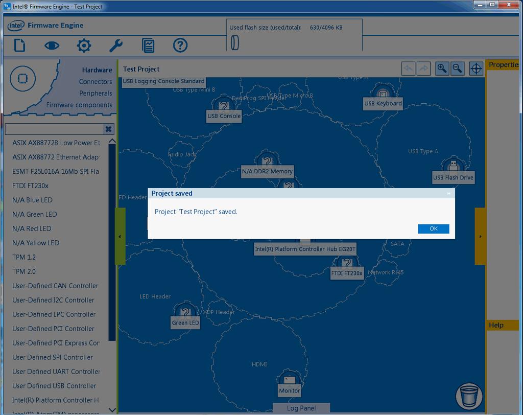
19 13
20 Working with Projects Save As (Back Up a Project to a new name) In the Menu Bar, CLICK Project > Load Select the project from the Project name pulldown The project comes up In the Menu Bar, CLICK Project > Save As Enter your New project name in the Save As menu Either accept the default project path or specify a New Project path Click OK to accept or Cancel to exit this menu choice without saving The project is saved to the name and path specified. 14

21 Deleting a Project You may wish to delete a project to reclaim used drive space or just because that project is complete. To permanently remove a project, CLICK Project > Delete. Then select the project name from the dropdown and CLICK OK 15


22 Working with Projects To permanently remove a project, select Project > Delete. 16

23 Then select the project name from the dropdown: This example shows "tester" selected. Click OK. 2.3 Building your Firmware Image When the project is complete the image can be assembled by clicking the Build icon from the Menu Bar. NOTE: Make certain that you have selected the required components and components of the Firmware image before using Build. Otherwise, the resulting firmware image may not function as needed. Build Options NOTE: NOTE: If you select Enable OS Compiler on the Options > Application > Application options >OS Compiler tab, you will be presented with additional Build menu options. Clicking on Enable OS Compiler splits Build into Firmware image (regular Build) and OS image (compiled image). See Application CLICK Firmware Image to build your project as project firmware. CLICK OS Image to save the project to your OS outside of this application. 17
24 Working with Projects Build and the Log panel When you perform a Build, the Log Panel (bottom of your screen, below the MAIN panel) returns two critical pieces of data: INFO: That a build is in process The path to the Build results. By default, Build put results in files found at /users/<yourname>/intel/intel(r) Firmware Engine /<projectname>/output/<filename>. This is the format followed in the figure above. It shows SUCCESS (or failure) of the Build and time and date stamp for the Build A hyperlink enabling a flash update is also given:. The OUTPUT directory path is "INFO: C:\Users\mporter\Documents\OC\Tester\OUTPUT\Tester.fd (click to update flash) " "Tester.fd" is the file you use to flash your board. Although the default path is not used in this example, the Log Panel provide the path for reference Building--Flash Update Click on the Firmware image pull-down to create a firmware image per the parameters given in the Options > Application > Application options. By default, Build put results in files found at /users/<yourname>/intel/intel(r) Firmware Engine /<projectname>/output/<filename>. This is the format followed in the figure below, in the Log Panel. 18
25 When you CLICK on (click to update flash), a the build process initiates and a series of moving gears will occupy the screen. When finished the results output to the Log panel. STOP (Stop the current build) This option appears only when a build is in process. It does just what it indicates: it cancels the build in process. CLICK on this if you are in the middle of a build and need to stop the build process for any reason (additional changes, wrong project, and so on). 19
26 Working with Projects The Log panel will return with "INFO: Build stopped" 20
27 2.4 Adding Applications and Drivers to a Project When you need to incorporate an application or driver that is not in your repository, do this: Click on the Project icon in the Menu Bar. Scroll down the Project menu dropdown menu to Add Files. Click on the Add Files option: 21
28 Working with Projects The Add files menu appears: 22

29 Added files will appear on the appropriate list for reordering of boot files or removal of either UEFI Drivers or boot files. Reordering and Remove BUTTONS Notice the Application control buttons along the far right side: Move up, Move down, Remove, and the Drivers control button, Remove. In the example below we are preparing to remove the helper driver Firmware Volume Load File Module. Remove is highlighted--double click to remove. 23
30 Working with Projects Add Files > Applications There are three Applications buttons corresponding to the types of applications or files you can add. Add Firmware Application Add Bootable File Add Data File Add Files > Drivers There are four Drivers buttons corresponding to the various types of drivers you can add. Add Helper Driver. Add UEFI Driver Add UEFI Driver with metadata Add UEFI driver from Source 24
31 Add Firmware Application Note that Firmware Applications figure below contains examples of the type of applications residing in your repository. This will depend on your reference board and repository contents. If you CLICK on one of the Applications in repository, the Help box displays information about the chosen application. CLICK on the application to be added and CLICK OK to add it to your firmware image Reordering and Remove BUTTONS Notice the Application control buttons along the far right side: Move up, Move down, Remove. Use these to reorder the preference or to remove a previously added file. Add Bootable File This is for adding files that the system will try to run when the firmware image boots. CLICK the Add bootable file button to display the Add bootable file window. This window allows you to browse to the file to be added to your bootable content. 25
32 Working with Projects CLICK OK to accept your choice or Cancel to back out of this option. Added files will appear on the appropriate list for reordering of boot files or removal Reordering and Remove BUTTONS Notice the Application control buttons along the far right side: Move up, Move down, Remove. Use these to reorder the preference or to remove a previously added file. Add Data File This is for adding data files that the system may access when the firmware image is booted up. CLICK the Add data file button to display the Add data file window. This window allows you to browse to the data file to be added to your bootable content. 26

33 CLICK OK to accept your choice or Cancel to back out of this option. Added files will appear on the appropriate list for reordering of boot files or removal Reordering and Remove BUTTONS Notice the Application control buttons along the far right side: Move up, Move down, Remove. Use these to reorder the preference or to remove a previously added file. Add Helper Driver Note that Helper Drivers figure below contains examples of type of drivers residing in your repository. CLICK on the Helper driver button for a list of helper drivers available. The Help box displays information about the chosen driver. CLICK the driver to be added and CLICK OK to add it to your firmware image. The window returns a display showing the chosen driver as selected. 27
34 Working with Projects CLICK OK to accept your choice or Cancel to back out of this option. Added drivers will appear on the appropriate list Remove Button In the example below we are preparing to remove the helper driver Firmware Volume Load File Module. Remove is highlighted--double-click to remove. 28
35 Adding a UEFI Driver Using Intel Firmware Engine it is possible to add UEFI drivers to the project. To do this: CLICK on the Project icon in the Menu Bar. Scroll down the Project menu dropdown menu to Add Files. CLICK on the Add Files option: 29
36 Working with Projects The Add files window appears. 30
37 Click on Add UEFI Driver This button is for adding a UEFI driver module driver. This Firmware Image (EFI) file will be treated as a UEFI driver when the system is booted and the file is run. A dialog box will appear asking for the specific location information. ENTER or browse to navigate to the file/files you would like to add. CLICK OK and the selected file/files will be added. 31
38 Working with Projects Add UEFI Driver with metadata Using Intel Firmware Engine it is possible to add a UEFI driver with metadata to the project. To do this: Click on the Project icon in the Menu Bar. Scroll down the Project menu dropdown menu to Add Files. Click on the Add Files option: The Add files window appears. There are seven buttons corresponding to the various types of files you can add. 32

39 Click on Add UEFI Driver with Metadata This button is for adding a UEFI Driver and its metadata. Here, metadata refers to descriptions of the driver and how it was compiled. A dialog box will appear asking for the specific location information. 33
40 Working with Projects Enter or browse to navigate to The.inf The Workspace (file location). Click Ok and the selected file/files will be added. Add UEFI driver from Source Using Intel Firmware Engine it is possible to add a UEFI driver from source to the project. To do this: Click on the Project icon in the Menu Bar. Scroll down the Project menu dropdown menu to Add Files. Click on the Add Files option: The Add files window appears. There are seven buttons corresponding to the various types of files you can add. 34
41 Click on Add UEFI Driver from Source This button is for adding a UEFI driver from the source code. A dialog box will appear, asking for the specific location information. 35

42 Working with Projects ENTER or browse to navigate to the.inf file, the Workspace (file location) the.dsc file for the UEFI driver. Click OK and the selected file/files will be added. 2.5 Making Project Properties Changes Project > Properties > Project Settings You must have a project open to make changes. Everything is project-based. Upon opening a project or creating a new project the user will be asked a series of Settings, Questions and Repository ties. The sections made will prompt further information if necessary and dictate what settings are present in the final firmware image. On the Project icon menu there is an option called Properties. Properties allows you to specify settings for your firmware image. This is where you select the options you wish to enable for your open project. You can change information about the project properties such as the path or your version number, as well as change the settings (questions) you selected when you created the project. See the specific field information below for details. The basic steps to change the settings in a project: Open the project. Select Project > Properties. 36

43 Make the property changes. Save the project. Let's take a closer look: Making properties changes (general) Click the Properties button. A list of settings appears. Select or deselect each setting for your final image. Selected items will show a box with diagonal fill: Deselected items will show an empty box: Click the OK button. Project Settings Windows and Tabs The Project Settings window appears. The Project settings tabs are Settings tab 37

44 Working with Projects Questions tab Settings tab In the Settings tab you will confirm or edit the following: This is the repository project path box. Select the platform name from the Platform name box. ENTER the Project path or enter the desired location for the project file to be stored. Enter the Project name in the Project name text box Assign and enter a version ID in the Version ID text box. Tool version is the version of the application tool. This is the tool version this project uses. Click OK to accept the defaults or to accept the changes you make to the settings Questions tab Click on the Questions tab. 38
45 NOTE: the questions listed in this tab will vary according to the properties of your project and its various components. The example below is representative of the type of questions, but the specifics will vary according to the project. The specific questions will also change according to changes you make to your project, and the various components and their associated properties. Selected items CLICK on the boxes to select or deselect each menu item according to your needs. CLICK OK. The project opens. Recovery File Generation and Firmware Update File Generation (and their subsettings) entail important security and authentication options. 39
46 Working with Projects 40
47 3 Firmware Update and Firmware Recovery Examples *KEEP THE PRIVATE KEY SECRET: The method Intel Firmware Engine uses to determine that images are valid is known as a digital signature. This well-known method is based on the RSA-2048 cryptograph algorithm. RSA-2048 is an example of a technology known as public key (PK) cryptography. The benefit of this technology is that any image encrypted by the private key may be decrypted by the corresponding public key (and vice versa) but an image encrypted by either key cannot be decrypted by that key. Because we don t care who can verify that our image is valid, we don t need to keep the public key secret. (A key in this instance is simply a long binary number 2048 bits in this case. You must keep the private key secret because it is the method by which the update process determines that the update is valid. If that private key becomes public, anyone could sign updates that the product s update verification could not distinguish a bad from a good update. There are many sources on the internet that detail methods for keeping private keys secret. We strongly recommend a review of several sites to determine the level of secrecy your application requires. 3.1 Project Settings workflows The Intel Firmware Engine application allows you to quickly configure and build a firmware image. You can plan this before creating a new project or you can load and reconfigure a project at any time. If you are creating a production build we strongly recommend RSA 2048 SHA 256 based image authentication using a custom signing key. Of the choices available in the Intel Firmware Engine, it provides the most complete and secure authentication and is the only recommended choice for production builds. To plan or to reconfigure your project you should understand that these settings will be present (or not) depending on the platform and various configuration choices that you may make. Because they are platform-dependent, we will only describe two settings (and their authentication settings) that may be present and are critical to security. Two-part process Selecting Enable Recovery File Generation or Firmware Update File Generation (or both) causes the Firmware Recovery and Firmware Update Authentication Support menu to appear. What does this mean? 41
48 Firmware Update and Firmware Recovery Examples You must make authentication choices in order to enable a recovery file or to enable a firmware update file. 3.2 Recovery and Firmware Update: Basic Selections You can choose to enable generation of a recovery file a firmware update image both recovery and firmware update images Firmware Update All firmware images generated by Intel Firmware Engine support the firmware update feature, but firmware update images are not generated by default. Enabling Firmware Update allows the main firmware image (or the user provided files) in the firmware image to be updated with new or updated content. Workflow: Enable Firmware Update File Generation. (Firmware update images are not generated by default.) It requires adding the UEFI Shell application to your target. Project > Properties > Project Settings (Questions tab)-(include UEFI Shell Boot Support then apply or OK) Recovery File A recovery file is used when the platform s main firmware image in the platform has been corrupted and is no longer bootable. The recovery feature allows the main firmware image to be read from a storage device such as a USB Flash Drive, placing the platform in a bootable state, where the main firmware image can be repaired or updated. Workflow: Enable Recovery File Generation. (Intel Firmware Engine does not generate the recovery image by default.) To support recovery, the user must select a recovery device (one or more storage devices used for recovery). Enable Recovery Peripherals Once a recovery device is selected, the firmware images generated by Intel Firmware Engine support both recovery and firmware update features. Selecting either or both of these brings up a sub-menu of Authentication selections. Before either a recovery or firmware update image can be used, you must select an image authentication method: 42
49 3.3 Recovery and Firmware Update: Authentication Selections and Workflows If YES to either firmware recovery or firmware update (or both), you must also determine which authentication to support: Authentication Disabled This is the do nothing option. RISKS: It entails the highest risk because there are no image integrity checks whatsoever. (That may not matter for a development build.) Not recommended for production builds. BENEFITS: It has lower overhead for firmware image size and boot performance than the other image authentication methods. Workflow: Authentication Disabled Tasks Select Authentication Disabled configuration selection in Project Settings. Click OK. Build the image. CRC-32 Based Authentication RISKS: Only basic image integrity checking occurs. It is not secure and does not verify the origin of the new image. (That may not matter for a development build.) Not recommended for production builds. BENEFITS: This configuration has lower firmware image size and boot performance overhead than either of the RSA 2048 SHA 256 based image authentication types. Workflow: CRC-32 Based Authentication Tasks The configuration selection in Project Settings. Click OK. Build the image 43
50 Firmware Update and Firmware Recovery Examples Test Signing Key: RSA 2048 SHA 256 based image authentication using test signing key RISKS: This method entails a greater impact to firmware image size overhead and boot performance. Entails greater implementation effort (OpenSSL installation and configuration, and making Common Firmware Settings across Modules selections) Not recommended for production builds. (Actual signing key implementation does not occur.) BENEFITS: The image signing facilities are simulated, so actual establishment of these facilities is not required: reduces your work and is less complex to implement. These simulated signing facilities mimic using a custom signing key. In other words, it acts like the custom key (except for the actual security) and is a lower-impact way to test for security. It is also a good test for space. Workflow: Test Signing Key Tasks Enable Test Signing Key Install Open SSL Configure OpenSSL Configure settings in Firmware Components>Common Firmware Settings across Modules Build the image. Custom Signing Key: RSA 2048 SHA 256 based image authentication using a custom signing key RISKS: This method entails a greater impact to firmware image size overhead and boot performance. Entails greater implementation effort and extensive requirements (OpenSSL installation and configuration, generation of private keys, custom tools and the establishment of imaging signing facilities.) BENEFITS: Highest level of security available in this application. Suitable for production builds. Workflow: Custom Signing Key Tasks Enable Custom Signing Key 44
51 Enable Recovery peripheral(s) Install Open SSL Configure OpenSSL Generate new Public Key Generate new Private Key Implement the custom signing tool Configure the platform to use the custom signing tool Import Public key into Intel Firmware Engine Common Firmware Settings across Modules Build the image. 3.4 Enable generation for Recovery Images and Firmware Update Images This can be done as you create a project or afterward. To enable recovery images and firmware update images when you create a project, go to Create Project. (In the Questions tab, the second page of the new project dialog you can enable either.) This is basically the same dialog as you get in the Properties>Questions tab, given below. After you have created a project, you can enable the generation of recovery images and firmware update images by selecting Project -> Properties. In the Project settings dialog select the Questions tab. Enable the options you need for your project by checking the corresponding boxes. For instance, you can enable generation of recovery images and firmware update images independently. This dialog, with the default settings for Recovery and Firmware Update being disabled, is shown in the following figure: 45
52 Firmware Update and Firmware Recovery Examples 3.5 Enable Recovery Peripherals Project Settings When a peripheral device supports use as a recovery device, the peripheral device has a Property called Enable OS Boot and/or Recovery Support. This Property can be set from either Gear View or Tree View. Select the recovery device you wish to support. To choose a device, click on the component and open the Properties tab on the right. The example below shows the USB Flash Drive as the recovery selected. The USB FLASH Drive peripheral selected and the Properties pane with the drop down menu for the Enable OS Boot and/or Recovery Support question. When using the peripheral for recovery only, select Firmware Recovery from the drop down menu. When using the peripheral for firmware recovery and to boot an operating system, select OS Boot and Firmware Recovery from the drop down menu. CLICK on Apply at the bottom of the properties panel. Repeat these steps for each peripheral that will be used as a firmware recovery device. 46

53 3.6 Installing OpenSSL Utilities You must install the Open SSL command line utilities in order to configure a platform project with an RSA 2048 SHA 2456 based image authentication type. [WARNING] The OpenSSL Project owns these utilities. They are subject to change without notice. Therefore, what follows is an approximation of the installation process and should not be taken as an absolute or complete set of instructions. Please note the disclaimer and warning on the opening page of the OpenSSL site ( To install the Open SLL command line utility: The OpenSSL Project ( points to a list of OpenSSL binary distributions at: Or: Choose your OS and download the appropriate package. Download the sources from the OpenSSL Project and build the command line utilities. Intel Firmware Engine supports the use of OpenSSL 0.9.8za and above. 47

54 Firmware Update and Firmware Recovery Examples Note: Be aware that building the command line utilities entails selection of several variables. For instance, a Microsoft Windows* installation involves the following choices: the version (at least three available, full or lite installation, and 64bit or 32bit. After installing OpenSSL command line utilities, you must set the OS Environment variable OPENSSL_PATH. 3.7 Configure OpenSSL Utilities Note: Intel Firmware Engine must be restarted after setting or changing this OS environment variable. To configure OpenSSL utilities: 1) Click Start button 2) Right click on Computer 3) Select Properties 4) Select Advanced System Settings 5) Select Environment Variables 6) Select System Variables 7) Create New System Variable and at the Variable value enter (whatever you need to enter) as shown below. 8) Return to the Intel Firmware Engine application after determining your authentication method and installing the required utilities. You will use the application settings to enable Recovery peripherals. Restart Intel Firmware Engine after setting or changing this OS environment variable. Do not neglect this step; it is imperative. Authentication Disabled Project Settings When you create a project: Go to Project > New Project 48
55 Verify Source Project, add in the New Project name and CLICK OK Intel Firmware Engine clones the project and brings you to the Project Settings window, and the Questions tab Pick Enable Recovery File Generation, Enable Firmware Update File Generation, or both This brings up the Firmware Recovery and Firmware Update Authentication Support sub-menu Select Authentication Disabled from the pulldown Click OK On demand: Go to Project > Properties This brings up the Project Settings window CLICK on the Questions tab Pick Enable Recovery File Generation, Enable Firmware Update File Generation, or both This brings up the Firmware Recovery and Firmware Update Authentication Support sub-menu Select Authentication Disabled from the pulldown Click OK CRC-32 Based Authentication Project Settings When you create a project: Go to Project > New Project Verify Source Project, add in the New Project name and CLICK OK Intel Firmware Engine clones the project and brings you to the Project Settings window, and the Questions tab Pick Enable Recovery File Generation, Enable Firmware Update File Generation, or both This brings up the Firmware Recovery and Firmware Update Authentication Support sub-menu Select CRC-32 based automation from the pulldown Click OK On demand: Go to Project > Properties 49
56 Firmware Update and Firmware Recovery Examples This brings up the Project Settings window CLICK on the Questions tab Pick Enable Recovery File Generation, Enable Firmware Update File Generation, or both This brings up the Firmware Recovery and Firmware Update Authentication Support sub-menu Select CRC-32 based automationfrom the pulldown Click OK Test Signing Key Project Settings Make sure you have completed Installing OpenSSL Utilities & Configure OpenSSL Utilities before proceeding. If authentication support is set to RSA 2048 SHA 256based authentication using a test signing key, no additional settings within the application are required to generate recovery or firmware update images for that authentication type. Details on installing and configuring the Open SSL command line utilities are shown in Installing OpenSSL Utilities & Configure OpenSSL Utilities. In the Firmware Components -> Common firmware settings across modules dialog an additional setting is shown called One or more SHA 256 Hashes of RSA 2048 bit public keys used to verify Recovery and Capsule Update images. Use this existing setting. The figure below shows this read-only (default) setting in this dialog. This 32-byte value that is the SHA 256 hash of the RSA 2048 bit test signing public key that is included with Intel Firmware Engine. Producing the firmware Image for a Test Signing Key At this point all of the steps required to configure a Test Signing Key have been completed. 50

57 Clicking the Build icon produces a firmware image that performs recovery and firmware update image authentication using the test signing public key key. produces recovery and firmware update images that are signed using the test signing public When the platform is booted using this firmware image, a warning is displayed on the console. This indicates that the use of the test signing key has been detected and that the firmware image is not a production firmware image. Custom Signing Key (RSA 2048 SHA 256) Setting authentication support to RSA 2048 SHA 256 based authentication using a custom signing key requires several additional steps a Build action will succeed. These steps include: Enable Custom Signing Key (Recovery_and_Firmware_Update:_Authentication_Selections_and_Workflows) Enable Recovery Peripherals Install and configure Open SSL command line utilities. Generating_Private_and_Public_Keys Perform_Test_Signing_using_the_Rsa2048Sha256Sign_utility* Configure_the_Platform_to_use_Custom_Signing_Tool Import_public_key_file_into_Common_Settings_across_Modules Build_a_production_image 51
58 Firmware Update and Firmware Recovery Examples *KEEP THE PRIVATE KEY SECRET: The method Intel Firmware Engine uses to determine that images are valid is known as a digital signature. This well-known method is based on the RSA-2048 cryptograph algorithm. RSA-2048 is an example of a technology known as public key (PK) cryptography. The benefit of this technology is that any image encrypted by the private key may be decrypted by the corresponding public key (and vice versa) but an image encrypted by either key cannot be decrypted by that key. Because we don t care who can verify that our image is valid, we don t need to keep the public key secret. (A key in this instance is simply a long binary number 2048 bits in this case. You must keep the private key secret because it is the method by which the update process determines that the update is valid. If that private key becomes public, anyone could sign updates that the product s update verification could not distinguish a bad from a good update. There are many sources on the internet that detail methods for keeping private keys secret. We strongly recommend a review of several sites to determine the level of secrecy your application requires Install and configure OpenSSL now Install and configure Open SSL command line utilities. Rsa2048Sha256GenerateKeys.exe and Rsa2048Sha256Sign.exe Intel Firmware Engine provides two command line utilities to support RSA 2048 SHA 256 signing: Rsa2048Sha256GenerateKeys.exe and Rsa2048Sha256Sign.exe Generating Private and Public Keys Rsa2048SHa256GenerateKeys.exe is used to generate a new private key file (PEM file) and also to generate a new public key file associated with the new private key file. To generate new keys, open a command prompt to these tools can be run. The directory these tools re installed is typically c:\program Files (x86)\intel\intel(r) Firmware Engine\ \Bin\Win32. The version value of may be different depending on the release of Intel Firmware Engine installed. The help for the command line tool Rsa2048Sha256GenerateKeys.exe is shown below: Rsa2048Sha256GenerateKeys.exe - Copyright (c) 2013, Intel Corporation. All rights reserved. usage: Rsa2048Sha256GenerateKeys.exe [options] optional arguments: -o [filename [filename...]], --output [filename [filename...]] 52
59 format specify the output private key filename in PEM -i [filename [filename...]], --input [filename [filename...]] format specify the input private key filename in PEM --public-key-hash PUBLICKEYHASHFILE 256 specify the public key hash filename that is SHA --public-key-hash-c PUBLICKEYHASHCFILE hash of 2048 bit RSA public key in binary format 256 format -v, --verbose -q, --quiet --debug [0-9] --version -h, --help specify the public key hash filename that is SHA hash of 2048 bit RSA public key in C structure increase output messages reduce output messages set debug level display the program version and exit display this help text New Private Key In order to generate a new private key file (PEM file) and its matching public key file, run the command shown below. The names of the output files can be modified as needed. The directory shown in the following example will need to exist or to be created: c:\program Files (x86)\intel\ Intel(R) Firmware Engine \ \Bin\Win32\Rsa2048Sha256GenerateKeys.exe o c:\keys\myprivatekey.pem -public-key-hash c:\keys\mypublickey.bin Only the binary file format of the public key is supported. Using other file formats may cause firmware not to function as expected. The PEM file created contains a private key that must be protected. Intel Firmware Engine does not provide any facilities to protect the private key. Instead you are responsible for the protection of private keys. *KEEP THE PRIVATE KEY SECRET: The method Intel Firmware Engine uses to determine that images are valid is known as a digital signature. This well-known method is based on the RSA-2048 cryptography algorithm. RSA-2048 is an example of a technology known as public key (PK) cryptography. The benefit of this technology is that any image encrypted by the private key may be decrypted by the 53
60 Firmware Update and Firmware Recovery Examples corresponding public key (and vice versa) but an image encrypted by either key cannot be decrypted by that key. Because we don t care who can verify that our image is valid, we don t need to keep the public key secret. (A key in this instance is simply a long binary number 2048 bits in this case. You must keep the private key secret because it is the method by which the update process determines that the update is valid. If that private key becomes public, anyone could sign updates that the product s update verification could not distinguish a bad from a good update. There are many sources on the internet that detail methods for keeping private keys secret. We strongly recommend a review of several sites to determine the level of secrecy your application requires Perform Test Signing using the Rsa2048Sha256Sign utility You must use an additional tool to consume the new private key file PEM file in order to use PEM file for signing recovery image and firmware update images. This could be a custom tool to adapt to different signing environments. A simpler method is to re-use the Rsa2048Sha256Sign.exe utility to perform test signing to sign images using the newly generated PEM file. This utility is provided with Intel Firmware Engine By default the Rsa2048Sha256Sign.exe utility uses the default test signing key, but this utility also supports an optional parameter to specify a custom signing key from a PEM file. The help for the Rsa2048Sha256Sign.exe utility is shown below. Rsa2048Sha256Sign.exe - Copyright (c) 2013, Intel Corporation. All rights reserved. usage: Rsa2048Sha256Sign.exe -e -d [options] <input_file> positional arguments: input_file specify the input filename optional arguments: -e encode file -d decode file -o filename, --output filename specify the output filename --private-key PRIVATEKEYFILE specified, a specify the private key filename. If not test signing key is used. -v, --verbose -q, --quiet increase output messages reduce output messages 54
![--debug [0-9] --version -h, --help set debug level display the program version and exit display this help text An example batch script called c:\keys\mysigntool.](/docs-images/72/66921684/images/61-0.jpg "cmd that uses the new PEM file generated in the previous step would be: Rsa2048Sha256Sign.exe --private-key c:\keys\myprivatekey.pem %1 %2 %3 %4 %5 %6 %7 %8 %9 Rsa2048Sha256Sign.")
61 --debug [0-9] --version -h, --help set debug level display the program version and exit display this help text An example batch script called c:\keys\mysigntool.cmd that uses the new PEM file generated in the previous step would be: Rsa2048Sha256Sign.exe --private-key c:\keys\myprivatekey.pem %1 %2 %3 %4 %5 %6 %7 %8 %9 Rsa2048Sha256Sign.exe is the custom signing tool that we use for these operations with Intel Firmware Engine Configure the Platform to use Custom Signing Tool Once authentication support is set to RSA 2048 SHA 256 based authentication using a test custom signing key, and Apply is selected, an additional setting will appear. This setting is Firmware Recovery and Firmware Update Custom Signing Tool Path. Fill this setting in with the full path to the custom signing tool (the one you just created ) Always put this path in quotes ( ) (The tool s path can have spaces and must be quoted so that the tool can be run successfully.) This custom signing tool is the one that Intel Firmware Engine uses to sign Firmware Recovery and Firmware Update image using the new private key file (PEM file). 55

62 Firmware Update and Firmware Recovery Examples Configure Custom Signing Tool An additional setting is shown in the Firmware Components ->Common firmware settings across modules dialog called One or more SHA 256 Hashes of RSA 2048 bit public keys used to verify Recovery and Capsule Update images. A Capsule is a file that contains a firmware update image. The figure below shows this setting in this dialog. This is a 32-byte setting that is the SHA 256 hash of RSA 2048 bit, the test signing public key that is included with Intel Firmware Engine. This setting supports a Browse button so the 32-byte value can be changed to the public key file generated in the previous step Import public key file into Common Settings across Modules Press the Browse button and select the public key file c:\keys\mypublickey.bin generated in the previous step. Only the binary file format of the public key is supported. Using other file formats may cause firmware not to function as expected. 56

63 Build a production image At this point all of the steps require to configure a Custom Signing Key have been completed. Pressing the Build button produces a production firmware image that performs recovery and firmware update image authentication using the specified public key and also produces recovery and firmware update images that are signed using the specified private key. If the custom signing tool fails, the build log shows the details of the failure. These are typically related to incorrect file paths to the custom tool or an incorrect file path to the private key file. 3.8 Using and testing a Firmware Update or Recovery image Using a Recovery Image An extra output file (FvMain.fv) is generated in the OUTPUT directory of the platform project when generation of a recovery image is enabled in the Questions tab of Project -> Properties, and the Build button is selected.. Sample contents of the OUTPUT directory for a platform with the recovery feature enabled are shown below. The output directory contains the firmware image.fd file along with a number of report files along with the additional FvMain.fv file. MinnowCustomKey\ OUTPUT\ ConfSettings_MinnowCustomKey_2014_06_30_17_29_57.csv FirmwareInventory_MinnowCustomKey_2014_06_30_17_29_57.csv FvMain.fv MinnowCustomKey.fd 57
64 Firmware Update and Firmware Recovery Examples PlatformInventory_MinnowCustomKey_2014_06_30_17_29_57.csv report.txt To test the recovery image Copy the FvMain.fv to the root directory of a peripheral that was enabled as a recovery peripheral (USB Flash Drive in the example above) and is formatted with a FAT file system. Connect the peripheral to the target platform, and power on the target platform with a recovery boot enabled (usually a jumper or a button). If the feature is working correctly, then the recovery image should be loaded from the recovery peripheral instead of the platform FLASH. Using a Firmware Update Image Extra output files are generated in the OUTPUT directory of the platform project when generation of a firmware update images is enabled in the Questions tab of Project -> Properties and the Build button is selected. Sample contents of the OUTPUT directory for a platform with the firmware update feature enabled are shown below. The output folder contains the firmware image.fd file along with a number of report files along with the additional CapsuleApp.efi, FVMAINCAPSULE.Cap, and PAY_LOADCAPSULE.Cap files. MinnowCustomKey\ OUTPUT\ CapsuleApp.efi ConfSettings_MinnowCustomKey_2014_06_30_17_29_57.csv FirmwareInventory_MinnowCustomKey_2014_06_30_17_29_57.csv FVMAINCAPSULE.Cap MinnowCustomKey.fd PAY_LOADCAPSULE.Cap PlatformInventory_MinnowCustomKey_2014_06_30_17_29_57.csv report.txt To test the firmware update image Copy the CapsuleApp.efi, FVMAINCAPSULE.Cap, and PAY_LOADCAPSULE.Cap files to a peripheral. This peripheral must be enabled as an OS boot peripheral (e.g. USB Flash Drive) and formatted with a FAT file system. Add the UEFI Shell application to your target. Connect the peripheral to the target platform and boot the target platform to the UEFI Shell application. From the UEFI Shell command prompt, find the file system that contains the CapsuleApp.efi, FVMAINCAPSULE.Cap, and PAY_LOADCAPSULE.Cap files. 58
65 Then run one of the following commands, FVMAINCAPSULE.cap or PAY_LOADCAPSULE.cap Each one updates a different part of the platform FLASH device. FVMAINCAPSULE.cap contains the main firmware image. PAY_LOADCAPSULE.cap contains the user provided files added through Project -> Add Files Fs0:\> CapsuleApp.efi FVMAINCAPSULE.Cap Fs0:\> CapsuleApp.efi PAY_LOADCAPSULE.Cap The system will reboot twice as each command is processed (That is, twice for : FVMAINCAPSULE.Cap and twice for PAY_LOADCAPSULE.Cap) It does this First, to authenticate the firmware update image and update the FLASH device. Second, to boot using the updated FLASH device. Once the final reboot complete, you ve finished updating your firmware. 59
66 Firmware Update and Firmware Recovery Examples 60
67 4 Working with Components This topic deals with adding Hardware, Connector and Peripheral components. When you add, you describe and select the hardware, connectors, peripherals or firmware components that define your firmware image. Adding and deleting components is central to customizing and defining your particular firmware image. Remember, when you add components you are selecting the component and adding the code that makes the component work. The processes are essentially the same for Hardware, Connectors and Peripherals. Adding or removing the wrong items will result in an incorrect firmware image because it will not match your platform board. See Changing_Firmware_Settings for information about Firmware Components. Where: Component List You can add by dragging and dropping a component to an approved or preferred landing spot in Gear View, or you can CLICK on your selection in Tree View. You can delete by a reversal of either process In addition you can use the Trashcan to Undo an item in Gear View, or select Deleted Components and select the component to Undo 61
68 Working with Components For information on filtering components, see Filtering Peripherals/Connectors/Hardware/Firmware To optimize your firmware, you need to specify exact connections, etc. You can accept default connections, properties and other settings in either view. We strongly advise you to review your choices (in either view) to make certain that they optimize your firmware and accomplish your goals. 4.1 Adding Components: Customizing the Firmware Image When you add a component, the properties and connections are made according to default settings from your (selected) reference platform, and some of these properties or connections may change. Also, the firmware for that component is added to the Firmware Components list for your derivative board. You add components for the firmware to create your (derivative) platform board. Customizing using Properties Tab and Connections Tab To customize component properties or connections, select the Properties or Connections tab along the right side of the main panel. (highlighted in the examples below) The properties and connections are the defaults from the selected reference platform and some may be changed. Changing Component Connections: Connections Tab Changing Component Properties: Properties Tab Where In the Component List panel you will notice menu items along the top. These items are: Hardware Connectors Peripherals Firmware components When you add a component the associated firmware is added to the firmware components list. Click on the menu item corresponding to the type of component you wish to change. 62

69 Adding Components: Gear view In the Component List navigation pane you will notice menu items along the top. The following applies to Hardware, Connectors and Peripherals: just substitute the type of component you wish to add. The following example adds a Hardware Monitor. Step 1. Select Hardware Step 2. Use the "drag and drop" feature Place the Monitor (your chosen component in this example) onto your landing spot--hdmi in this example. Notice that the component to be added and the approved spots for adding and connecting are highlighted in an orange outline. 63

70 Working with Components Changing Component Properties: Properties Tab You may want to change component properties. Notice the Properties tab along the right side. This allows you to select and customize the component properties. The Help panel below provides additional information Changing a Monitor Property (Example) In the example given above you need the Property "Monitor Display Technology Support" to be TV/HDTV. Click the "Monitor Display Technology Support" box (currently reading "VGA". Select "TV/HDTV" from the pop-up menu Click on APPLY at the bottom of the Properties panel. 64

71 Changing Component Connections: Connections Tab Removing a connection in the Connections menu may result in the gear view showing a disconnected circle. Your hardware is now added and the corresponding Firmware modules will be added to the platform. Notice the Connections tab along the right side. This is the location where the connections for a given component to your reference platform are reside. Here you override existing connections and customize the connections according to your particular platform requirements. The Help panel below provides additional information Disconnected items See View (View Menu--Text labels) for how to activate and deactivate text and connector text. The text and connector text information can either significantly clutter-up or significantly illuminate a particular view. Use these options according to your needs. Removing a connection in the Connections menu may result in the gear view showing a disconnected circle. 65
72 Working with Components Items that you disconnect will be moved to a disconnected gear. They have not been deleted, but they are disconnected. They are still used to compute module solution. You can view them to the right of your connected items. They are labeled "Disconnected". The example below shows USB Type A disconnected: Adding components: Tree view In Tree view, scroll to the component you want to add, Monitor, in this example. Expand the component type Right mouse click the component you want to add Select the component to add to The component will be added and the list expanded. The firmware for the component will be added to the Firmware Components list. Notice the Properties Tab along the right side. This allows you to select and customize the component properties. Aside from the Tree View beside it, the Properties tab functions the same on Gear View. This HDMI example has no properties that can be changed. 66

73 The Help panel below the Properties tab and Connections tab provide additional information about the selected component. Notice the Connections tab along the right side. Here you override connections settings and customize the connections according to your particular platform requirements. The Help panel below provides additional information. Aside from the Tree View beside it, the Connections tab functions the same on Gear View. This HDMI example has no properties that can be changed. The Help panel below the Properties tab and Connections tab provide additional information about the selected component. 67
74 Working with Components 4.2 Deleting Components Remember, when you delete components you are deselecting the component and removing the code that makes the component work. The processes are essentially the same for Hardware, Connectors and Peripherals. You would delete a component, for instance, if your platform board does not have that component, or if you have made a mistake in adding components. Deleting the wrong items will result in an incorrect firmware image because it will not match your platform board. To optimize your firmware, you need to specify exact connections, etc. You can accept default connections, properties and other settings in either view. We strongly advise you to review your choices (in either view) to make certain that they optimize your firmware and accomplish your goals. Deleting Components: Tree view Deleting Components: Gear view There are two ways to delete a component in Gear view: Select the component by right-clicking on it and then "Delete" from the pop-up panel. "Drag" the component to the Trashcan 68

75 4.3 Undo: Restoring a deleted component A typical use of undo would be if you have removed a component and then discover that you needed it after all. Removed items are listed in the Trashcan list. You may also select the undo icon to choose a deleted item to restore. This icon is enabled after a component is deleted. 69

76 Working with Components Undo: Gear View Undo: Tree View A typical use of undo would be if you have removed a component and then discover that you needed it after all. Removed items are listed in the Deleted components list. As with the Gear View example above, use the Undo icon or the trashcan to select and restore a deleted component. 70

77 4.4 Filtering Peripherals/Connectors/Hardware/Firmware See Changing Firmware Settings for changing firmware details. Tree View Filter There are minor differences in way the views handle the use of a filter. From Tree View (View, Changing Views) Click on the Filter textbox; above it, Inventory is the default, but you may also choose Firmware components to refine your filter Type in your filter criteria, such as "usb" Inventory Example Tree View displays the results for all instances in the project inventory, regardless of the type of component, even including any deleted components that meet the filter criteria. Click on Firmware components to view those results. From Tree View (View, Changing Views) Click on the Filter textbox; above it, Inventory is the default to refine your filter. Click on Inventory if Firmware components is highlighted. Type in your filter criteria, such as "usb" Notice the list of inventoried items, the various types and the details available in the main and Help panels. In this instance User Defined USB Controller is highlighted. 71
 Click on Firmware Components, then on the Filter textbox; Type in your filter criteria, such as \"usb\" Notice the")
78 Working with Components Firmware Components Example From Tree View (View, Changing Views) Click on Firmware Components, then on the Filter textbox; Type in your filter criteria, such as "usb" Notice the list of inventoried items, the various items and the details available in the Properties and Help panels. In this instance USB Bus Driver is highlighted. 72

79 Gear View Filter Gear view behaves differently. From Gear View CLICK on the Filter textbox Type in your filter criteria, such as "usb" To filter Hardware example to apply the filter and view the results for various types of components, you need to select them individually. That is, select Hardware, Connectors, Peripherals, Firmware components CLICK on Hardware CLICK on the Filter textbox Type "usb" Verify only items with usb are displayed, such as "User Defined USB Controller" 73
80 Working with Components To filter Connectors example Change to Connectors Click on the Filter textbox Type "usb" and verify only items with USB are displayed, such as USB Type Micro AB 74
81 To filter Peripherals example Change to Peripherals Click on the Filter textbox Type "usb" and verify only items with usb are displayed, Such as USB Hard Drive. 75

82 Working with Components To filter Firmware components example Change to Firmware Components Click on the Filter textbox in the Tree View Panel Type "usb" and verify only items with usb are displayed, such as USB Bus Driver 76

83 4.5 Changing Firmware Settings Firmware Components is where you change an existing project, not by adding firmware components, but by changing component settings. This includes the settings selected with your initial configuration. Note that adding or removing components will change these settings. filtering and changing Firmware Component settings Example: changing settings for the USB keyboard driver Firmware Component setting or Common firmware settings across modules (Common Settings)? Notice that below the Filter box, it reads Common firmware settings across modules. Below that the firmware components are listed. 77

84 Working with Components Common firmware settings across modules Don't let the terminology confuse you. Common firmware settings across modules are firmware component settings, but they are firmware component settings that apply to more than one component. That is, they apply across modules, throughout your firmware image. We provide examples of Changing the Baud rate for a serial port Filtering and directed to a common setting across modules Example: Changing the Baud rate for a serial port Properties: Step 1 CLICK on Common firmware settings across modules. The Properties panel refreshes with a list of properties that apply throughout your firmware image (across modules). The List: Step2 Scroll down the properties list to "Baud rate for serial port", then 78
85 Selecting from the List: Step 3 CLICK on the dropdown list for baud rate options. The example shows that the serial port baud rate is currently set to "921600". Make your change: Step 4 Make your selection/change. Apply: Step 5 To save your change Click Apply. To cancel your change Click Cancel. To revert to the default settings click Default. Example: finding a firmware setting across modules using the Search Choosing Common Firmware settings: step 1 79

86 Working with Components CLICK on Common firmware settings across modules. The Properties panel refreshes with a list of properties that apply throughout your firmware image (i.e., across modules). Search: step 2 You may enter a specific keyword to search for, in this example "video". In the resulting list you will see the item or items that contain "video". Look at the list,then use the Properties panel Search utility to search for video resolution Firmware Properties Navigation: Mouse-over and Help As you mouse-over the various Properties settings, such as Video horizontal resolution, the information in the Help Panel (to the right of the Properties panel) changes accordingly. In this example it reads "Video vertical resolution" "This PCD defines the video..." Changing the setting: step 3 Enter the desired value o replace the current value, "1024". 80
87 Apply: Step 4 Click the Apply button. Firmware Components Example: changing settings for the USB keyboard driver Filter: step 1 Filter for "usb" Select from the Firmware Components list: step 2 Select "USB Keyboard Driver" from the Firmware components list resulting from filtering for "usb." Change the setting: step 3 The Properties panel then lists the USB Keyboard Driver.(firmware component) properties. Navigation: Mouse-over and Help As you mouse-over the various Properties settings, the information in the Help Panel (to the right of the Properties panel) changes accordingly. For instance, if you mouse-over "Logging", there are no properties available to change, so the Help panel simply repeats the name, "Logging". However, if you mouse-over "Report Status Code Property", Help explains that the "The mask is used to control ReportStatusCodeLib behavior" and lists the bits 0-2 and what their associated codes mean. Changing the value The value of the USB Keyboard Driver's Debug Property is "0x27" in this example and you may change it to another value. Be aware that your choice may involve repercussions or conflicts. On the other hand, you may be changing this value to resolve a conflict. Apply: Step 4 Click the Apply button. 81
.")
88 Working with Components 4.6 Module Ties "Module ties" is a phrase to indicate that more than one component is tied to that firmware component. That is, two or more drivers satisfy the requirements of a particular component. Because only one can be used at a time, they have an order of preference (see below). Changing Module ties (order of preference) Notice this symbol the figure below. next to "Variable SMM Runtime Driver" and "NULL Memory Test Driver" in 82

89 You can choose any one of the components for your firmware component, but you should note that they are listed in order from most preferred to least preferred. If you click on the Module ties symbol the preferred order., it returns with a message such as this one: indicating 83

90 Working with Components This message indicates that first required module is the one most preferred, but you are free to change to the module that best suits the requirements of your firmware image. Modules in module ties are tied individually, which means that more than one module cannot work together as a module tie of one module. You can only choose one. 84
91 5 Working with Application, Repository and Debugger Options the Application and Debugger options apply to a development station and not the project. The Options menu varies depending on what has been configured in the Application options dialog. 5.1 Application The Application options dialog allows you to add third-party functionality to the application. This dialog shows four tabs. the Application options apply to a development station and not the project. You enter the path to the debugger, flash programmer, location to place an update file, etc., in the Path box and any code instructions you deem necessary in the Command-line parameters box. Debugger allows you to enable (or disable) a debugger by entering the path to your debugger and adding the command-line parameters to launch the debugger. Essentially it creates the option to access your debugger from within this application. Flash programmer allows you to add your flash programmer for use with the application OS compiler enables OS compiler functionality and two additional Build choices: Firmware image and OS image OS update enables an OS Update 85
92 Working with Application, Repository and Debugger Options 5.2 Application Options Debugger You may want to link a debugger to assist with your firmware image. the Debugger options applies to a development station and not the project. If Options > Debugger is grayed out (unavailable) go to Options > Application > Application options > Debugger and follow the instructions for activating this choice. Once the debugger is activated and configured, clicking Debugger will initiate your (configured ) debugger. Intel UEFI Development Kit Debugger Tool (Intel UDK Debugger Tool) is the debugger currently available for use within this application. Clicking on the Debugger option does not enable the debugger, but it does enable you to browse out to the location of your chosen debugger and start it. This is a prerequisite to enabling the debugger in the application. Click on the Application option. 86
 Enter any Command line parameters that apply.")
93 The Application Options window appears. Click on the Debugger tab Enable Debugger ( ) Browse to (or enter) the Path for the debugger. This is the path to the debugger executable (that you installed.) Enter any Command line parameters that apply. EXAMPLE: --auto=^fd^ Click OK Build Use your debugger Intel UEFI Development Kit Debugger Tool (Intel UDK Debugger Tool) is the debugger currently available for use within this application. (Double-click on) 87
\": Without the path to the Flash programmer, you will be unable to fully utilize this capability.")
94 Working with Application, Repository and Debugger Options Enabling a flash programmer Flash programmer (tab) When Flash programmer is enabled, it provides the workings for an option in the log file after a Build, a hyperlink make a flash update--"(click to update flash)": Without the path to the Flash programmer, you will be unable to fully utilize this capability. This capability allows you to flash your firmware image immediately after it is built. The steps are Enable flash programmer Build Update flash You need to go here: Enable Flash programmer, Browse to Path, and Command line parameters. Go to Options>Application Click on Application to bring up the Application options tabs. Click on the Flash programmer tab 88
95 Verify that Enable Flash programmer is enabled ( ) Then Browse to or enter the Path of the flash programmer. This is the path to the flash programmer executable (that you have installed.) EXAMPLE: C:\...\dcpcmd.exe Enter any Command line parameters that apply. EXAMPLE: --auto="^fd^" Click OK Build--Check the log panel for build success verification, the path to the build output, and a link to update the flash in the machine you are working on. Update Flash--Click the hyperlink reading "(click to update flash)" appended to the INFO message to update the flash in the machine you are working on. Flash using DediProg software with your new My-Project.fd created from the Build process Linking a Compiler to your firmware OS compiler (tab) 89

96 Working with Application, Repository and Debugger Options Enabling OS Compiler means that you can link a compiler to the firmware you build. Additionally, when you enable the OS Compiler options tab, it also activates two Build options: Firmware Image and OS Image. See Build > Build_Options. To clarify, once the OS complier is enabled, you can compile and then update the image. If you select Enable OS Compiler on the Options > Application > Application options >OS Compiler tab, you will be presented with additional Build menu options. Clicking on Enable OS Compiler enables the Firmware image and OS image choices for a Build. See Application Enable OS Compiler You need to go here: Enable OS programmer, Browse to Path, and Command line parameters: Go to Options>Application Click on Application to bring up the Application options tabs. 90
97 Click on the OS Compiler tab Verify that Enable OS Compiler is enabled ( ) Then Browse to or enter the Path of the OS compiler to be used. This is the path to the flash programmer executable (that you have installed.) Enter any Command line parameters that apply. EXAMPLES: --auto=^fd^ (for a flash image); - -auto=^bim^ (for a binary file update) Click OK Build Check the log panel for build success verification, the path to the build output, and a link to update the flash in the machine you are working on Update the image Click the hyperlink reading "(click to update flash)" appended to the INFO message to update the flash in the machine you are working on. 91
 Go to Options>Application Click on Application to bring up the four Application options tabs.")
98 Working with Application, Repository and Debugger Options Enabling OS Update Os update (tab) Go to Options>Application Click on Application to bring up the four Application options tabs. Click on the OS Update tab Verify that Enable OS Update is enabled ( ) 92
99 Then Browse to or enter the Path of the OS update. This is the path to the OS Update (that you have installed.) Enter any Command line parameters that apply Click OK Build Build> OS Image Your project builds, and in the Log panel indicated the path to the image file. Additionally it provides you the ability to "(click to update the OS image)" per the illustration below: 93
100 Working with Application, Repository and Debugger Options 5.3 Repository (Maintenance Tool) OPTIONS > REPOSITORY See Also Finding Repository, Toolset and BIM files Intel Firmware Engine Repository Maintenance Tool Overview These choices are found in the left panel. In the right panel you refine and adjust the output from your choice. DO NOT perform repository maintenance when you have a project open. Close projects before performing repository maintenance. Do not open projects until after you have finished performing repository maintenance. You may choose to perform Repository maintenance Package maintenance 94

101 Remote linking Obtain repository information The reference platform you receive with the reference board is read-only set of binary modules. You change particular settings through the application user interface. Remember, a repository is a workspace that is composed of packages. The initial repository is created as part of the initial install. A repository may be located either on local storage or a remote network server. This option brings up a separate tool for adding, removing, updating, remotely linking or searching in your repository: the Intel Firmware Engine repository maintenance tool. 95

102 Working with Application, Repository and Debugger Options Repository Maintenance 96
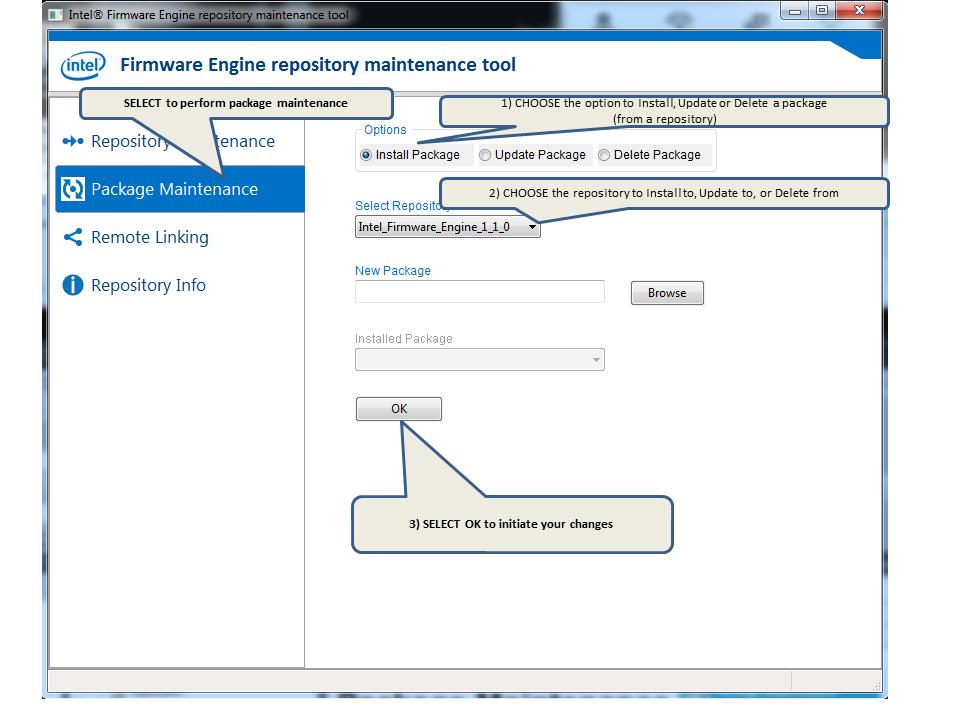
103 Package Maintenance 97

104 Working with Application, Repository and Debugger Options Remote Linking Perhaps you want to make a repository for several individuals. You can meet that goal by remotely linking to a repository. Note that maintenance (altering) of a repository can ONLY be performed on one locally available. 98
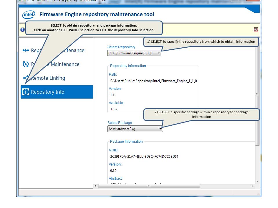
105 Repository Info 99
106 Working with Application, Repository and Debugger Options 100
107 6 Creating Reports 6.1 Report Overview There are three reports available in the Intel Firmware Engine that can provide you with a variety of information. These reports may be accessed through the Report selection on the menu bar. The reports are in.csv format and will be opened if you have.csv file types associated with a program. Platform Inventory Report Configuration Settings Report Firmware Inventory Report You can run these reports on demand. These reports are also generated at Build time, which generates a small window that provides the output path. You must note this path or you will be unable to find the report output. Tests are saved to this directory structure as well. 101
108 Creating Reports An explanation of each report follows: 6.2 Platform Inventory Report This report contains a summary of all hardware components (Build Of Materials--BOM) enabled by the user during the firmware component selection process and added to the binary file. 102
109 There may be components that are automatically enabled by the tool, behind the scenes, in order to enable particular components selected by the user. Those components will also be listed in this report. Platform Inventory Report EXAMPLE Intel(R) Firmware Engine Version: 1.0 Report Type:Platform Inventory Report Date:12/09/2014 Report Time:02:36:02 PM BOM Item Name Item Type Item Description Item Name is the name as displayed in the UI Item Type is one of Hardware, Connector, or Peripheral Item Description is the description from the repository Intel(R) Platform Controller Hub EG20T Hardware Describes the Intel(R) Platform Controller Hub EG20T. Winbond W25Q32FV 32Mb SPI flash Hardware Describes the W25Q32FV SPI flash device from Winbond. FTDI FT230x Hardware Full Speed USB2.0 to Basic UART Bridge, capable of operating up to 3MBaud with low power consumption. Intel(R) Atom(TM) processors E640 and E640T Hardware Describes the Intel(R) Atom(TM) processors E640 and E640T operating at 1.0GHz. N/A DDR2 Memory USB Flash Drive USB Console USB Logging Console Standard Hardware Describes a group of DDR2 Memory Components. Peripheral A generic USB Flash Drive or memory card. Peripheral Peripheral A generic USB based console through a standard USB cable that may support PC-ANSI, VT-100, VT-100+, or VT-UTF8. A USB based logging console used to display firmware logging messages received through a standard USB cable. 103
110 Creating Reports USB Keyboard Monitor Green LED Green LED Network RJ45 LED Header LED Header Audio Jack usd Socket USB Type Mini B USB Type A USB Type A XDP Header USB Type Micro B Peripheral A generic USB Keyboard. Peripheral A generic desktop Monitor. Peripheral A green LED. Peripheral A green LED. Connector A generic Network RJ45 connector. Connector A generic LED header. Connector A generic LED header. Connector A generic analog Audio Jack. Connector A generic Micro Secure Digital (usd) memory card Socket. Connector A generic standard USB Type Mini B connector. Connector A generic standard USB Type A connector. Connector A generic standard USB Type A connector. Connector extended Debug Port (XDP) Header communicates debug information over a JTAG interface. Connector A generic standard USB Type Micro B connector. DediProg SPI Header Connector DediProg SPI Header used to update an SPI FLASH. SATA HDMI Connector A generic standard internal SATA connector. Connector A generic standard HDMI video connector for transferring uncompressed video data and compressed or uncompressed digital audio data from a HDMI compliant source device to a compatible endpoint device. 104
111 6.3 Configuration Settings Report This report contains all the settings as configured in the firmware image. The platform configuration database (PCD) contains the configuration settings that the firmware modules will have. NOTE: Each line item is a variable inside the global PCD. These variables have its token items associated with them. Column show the type (PCD), the Name of the PCD token, the associated firmware module, the declared software type (Boolean or Integer), the value settings for your project build, the default value, and the description. Configuration Setting Report EXAMPLE Intel(R) Firmware Engine Version: 1.0 Report Type:Configuration Settings Report Date:12/09/2014 Report Time:11:45:13 AM PCD PCD - Question Pcd Name Referenced Name Pcd Type Current Value Default Value Pcd Description Pcd Name is the name as displayed in the UI Referenced Name is the human name of the module consuming this PCD Pcd Type is the same as ValueType from ConfigHLD Current Value is the current value 105
112 Creating Reports Default Value is the default value Pcd Description is the description from the repository System UUID None UINT8LIST [35, 239, 255, 19, 84, 134, 218, 70, 164, 7, 57, 201, 18, 2, 211, 86] [35, 239, 255, 19, 84, 134, 218, 70, 164, 7, 57, 201, 18, 2, 211, 86] Provides the BIOS System UUID to be used when generating the SMBIOS Type 0 structure. Boot Timeout (s) Console output column Console output row Video horizontal resolution Video vertical resolution None UINT None UINT None UINT None UINT None UINT The number of seconds that the firmware will wait before initiating the original default boot selection. A value of 0 indicates that the default boot selection is to be initiated immediately on boot. The value of 0xFFFF then firmware will wait for user input before booting. This PCD defines the Console output row. The default value is 80 according to UEFI spec. This PCD could be set to 0 then console output would be at max column and max row. This PCD defines the Console output row. The default value is 25 according to UEFI spec. This PCD could be set to 0 then console output would be at max column and max row. This PCD defines the video horizontal resolution. If this PCD is set to 0 then video resolution would be at highest resolution. This PCD defines the video vertical resolution. If this PCD is set to 0 then video resolution would be at highest resolution. Gigabit Ethernet None MAC Address UINT8LIST [255, 255, 255, 255, 255, 255] [255, 255, 255, 255, 255, 255] MAC address for the Gigabit Ethernet Controller in Intel(R) Platform Controller Hub EG20T. Default is 0xff, 0xff, 0xff, 0xff, 0xff, 0xff, 0xff. PCI Subsystem Device ID None UINT PCI Subsystem Device ID for all PCI controllers in the Intel(R) Platform Controller Hub EG20T. Default is 0xFFFF. 106
113 PCI Subsystem Vendor ID None UINT PCI Subsystem Vendor ID for all PCI controllers in the Intel(R) Platform Controller Hub EG20T. Default is 0xFFFF. Enter Firmware User Interface Support None BOOLEAN False False If the firmware has a User Interface this feature provides the ability to interrupt fast boot and enter the firmware user interface. Fast Boot Support None BOOLEAN False False Provides the ability to enable the Fast Boot feature of the BIOS. This enables the system to boot faster but may only enumerate the hardware that is required to boot the system. ACPI Hardware PCI Bar Enable BitMask None UINT Defines the bit mask that must be set to enable the ACPI hardware register BAR. ACPI Hardware PCI Bar Register Offset None UINT Defines the PCI Register Offset of the PCI device that contains the BAR for ACPI hardware registers. ACPI Hardware PCI Bus Number None UINT8 0 0 Defines the PCI Bus Number of the PCI device that contains the BAR and Enable for ACPI hardware registers. ACPI Hardware PCI Device Number None UINT Defines the PCI Device Number of the PCI device that contains the BAR and Enable for ACPI hardware registers. ACPI Hardware PCI Register Offset None UINT Defines the PCI Register Offset of the PCI device that contains the Enable for ACPI hardware registers. ACPI Hardware PCI Function Number None UINT8 0 0 Defines the PCI Function Number of the PCI device that contains the BAR and Enable for ACPI hardware registers. ACPI Timer None UINT Defines the ACPI register set base 107
114 Creating Reports IO Port Address address. Offset to 32- bit Timer register in ACPI BAR None UINT Defines the offset to the 32-bit Timer Value register that resides within the ACPI BAR. Reserved S3 Boot ACPI Memory Size None UINT Specify memory size with page number for a pre-allocated reserved memory to be used by PEI in S3 phase. The default size 32K. When changing the value make sure the memory size is large enough to meet PEI requirement in the S3 phase. Maximum variable size None UINT The maximum size of a single non- HwErr type variable. Baud rate for serial port None UINT Baud rate for the serial port. Default is baud. Enable serial port cable detection Serial port FIFO Control settings None BOOLEAN False False None UINT Indicates if the serial Tx operations will be blocked if DSR is not asserted (no cable). Default is FALSE. This PCD is ignored if PcdSerialUseHardwareFlowControl is FALSE. TRUE serial Tx operations will be blocked if DSR is not asserted. FALSE serial Tx operations will not be blocked if DSR is not asserted. FIFO Control Register (FCR) for the serial port. BIT0 - FIFO Enable. 0 = Disable FIFOs. 1 = Enable FIFOs. BIT1 - Clear receive FIFO. 1 = Clear FIFO. BIT2 - Clear transmit FIFO. 1 = Clear FIFO. BIT4..BIT3 - Reserved. Must be 0. BIT5 - Enable 64-byte FIFO. 0 = Disable 64-byte FIFO. 1 = Enable 64-byte FIFO BIT7..BIT6 - Reserved. Must be 0. Default is to enable and clear all FIFOs. Serial port None UINT8 3 3 Line Control Register (LCR) for 108
115 Line Control settings the serial port. This encodes data bits, parity, and stop bits. BIT1..BIT0 - Data bits. 00b = 5 bits, 01b = 6 bits, 10b = 7 bits, 11b = 8 bits BIT2 - Stop Bits. 0 = 1 stop bit. 1 = 1.5 stop bits if 5 data bits selected, otherwise 2 stop bits. BIT5..BIT3 - Parity. xx0b = No Parity, 001b = Odd Parity, 011b = Even Parity, 101b = Mark Parity, 111b=Stick Parity BIT7..BIT6 - Reserved. Must be 0. Default is No Parity, 8 Data Bits, 1 Stop Bit. Base address of serial port registers None UINT Base address of serial port registers in MMIO or I/O space. Default is 0x3F8. Enable serial port hardware flow control Serial port registers use MMIO None BOOLEAN False False None BOOLEAN True True Indicates if the serial port hardware flow control will be enabled. Default is FALSE. TRUE serial port hardware flow control will be enabled. FALSE serial port hardware flow control will be disabled. Indicates the serial port registers are in MMIO space, or in I/O space. Default is I/O space. TRUE serial port registers are in MMIO space. FALSE serial port registers are in I/O space. This flag is used to control the print out Debug message. Debug Message Print Level None UINT BIT0 - Initialization message. BIT1 - Warning message. BIT2 - Load Event message. BIT3 - File System message. BIT4 - Allocate or Free Pool message. BIT5 - Allocate or Free Page message. BIT6 - Information message. BIT7 - Dispatcher message. BIT8 - Variable message. BIT10 - Boot Manager message. BIT12 - BlockIo Driver message. BIT14 - Network Driver message. 109
116 Creating Reports BIT16 - UNDI Driver message. BIT17 - LoadFile message. BIT19 - Event message. BIT20 - Global Coherency Database changes message. BIT21 - Memory range cacheability changes message. BIT22 - Detailed debug message. BIT28 - Error message. Debug Property None UINT The mask is used to control DebugLib behavior. BIT0 - Enable Debug Assert. BIT1 - Enable Debug Print. BIT2 - Enable Debug Code. BIT3 - Enable Clear Memory. BIT4 - Enable BreakPoint as ASSERT. BIT5 - Enable DeadLoop as ASSERT. PCI Express This value is used to set the base None UINT Base Address address of PCI express hierarchy. Report Status Code Property None UINT8 7 7 The mask is used to control ReportStatusCodeLib behavior. BIT0 - Enable Progress Code. BIT1 - Enable Error Code. BIT2 - Enable Debug Code. Default Value of None PlatformLang STRING en-us en-us Variable Default current RFC 4646 language: (American) English. Internal Device Enables None UINT Determines which devices should be enabled within the chip. A bit value of zero will disable the device. A bit value of 1 will enable the device. In the case of the Azalia audio device, a value of 2 may also be used to configure the device for Auto mode. All reserved bits must be set to 0. Bit0 - PCI Express Root Port 1 Bit1 - PCI Express Root Port 2 Bit2 - PCI Express Root Port 3 Bit3 - PCI Express Root Port 4 Bit5:4 - Azalia Audio Bit6 - SMBus Bit31:7 - Reserved SMRAM size None UINT Defines the size of the SMRAM 110
117 The PCI Bus number for EG20T The PCI Device number for EG20T The PCI Function number for EG20T None UINT8 0 0 None UINT None UINT8 0 0 region to allocate from system memory for use by SMM. 0x : 1MB. 0x : 2MB. 0x : 4MB. 0x : 8MB. 0x : 16MB. PCI Bus number of the PCI root port connected to the Intel Platform Controller Hub EG20T. Default value of Bus 0 is PCI Root Port #0 of Intel Atom Processor E6xx. PCI Device number of the PCI root port connected to the Intel Platform Controller Hub EG20T Default value of Device 0x17 is PCI Root Port #0 of Intel Atom Processor E6xx. PCI Function number of the PCI root port connected to the Intel Platform Controller Hub EG20T Default value of Function 0 is PCI Root Port #0 of Intel Atom Processor E6xx. Divider setting for the PLL2 output. Setting EG20T UART BAUDDIV None UINT : Divide by 16. 1: Divide by 1. 2: Divide by 2. 3: Divide by 3. 4: Divide by 4. 5: Divide by 5. 6: Divide by 6. 7: Divide by 7. 8: Divide by 8. 9: Divide by 9. 10: Divide by : Divide by : Divide by : Divide by : Divide by : Divide by 15. Baud clock for EG20T UART None UINT8 1 1 Baud clock select (BAUDSEL). 0: UART_CLK pin. 1: 48 MHz. 2: 25 MHz. 3: 25 MHz. Setting None UINT8 8 8 Setting PLL2VCO (Phase 111
118 Creating Reports EG20T UART PLL2VCO LockedLoop Voltage Controller Oscillator) of CLKCFG register. 0: Disable PLL2VCO and BAUDDIV. 6: Multiply by 6. 7: Multiply by 7. 8: Multiply by 8. 9: Multiply by 9. 10: Multiply by : Multiply by 11. Reference clock for EG20T UART None UINT8 0 0 The Config Baud rate Reference Clock Select Register (BRCSR) controls the baud rate source clock selecting of UART. 0: Using PLLDIVCLK. Must use BAUDSEL and use PLL2VCO and BAUDDIV if PLL2VC0!= 0. 1: Using UART_CLK. Ignore BAUDSEL, PLL2VCO and BAUDDIV. Serial Port Clock Rate None UINT UART clock frequency is for the baud rate configuration. PCI Port Extended Transmit FIFO Size in Bytes None UINT Serial Port Extended Transmit FIFO Size. The default is 64 bytes. PCI Serial Device Info None UINT8LIST [23, 0, 164, 0, 0, 0, 68, 0, 10, 1, 84, 0, 255] [23, 0, 164, 0, 0, 0, 68, 0, 10, 1, 84, 0, 255] PCI Serial Device Info. It is an array of Device, Function, and Power Management information that describes the path that contains zero or more PCI to PCI bridges followed by a PCI serial device. Each array entry is 4-bytes in length. The first byte is the PCI Device number, then second byte is the PCI Function number, and the last two bytes are the offset to the PCI power management capabilities register used to manage the D0-D3 states. If a PCI power management capabilities register is not present, then the last two bytes in the offset is set to 0. The array is terminated by an array entry with a PCI Device number of 0xFF. For a non-pci fixed address serial device, such as an ISA serial device, the value is 0xFF. 112
119 PCD - Question Question Question Name Question Type Current Value Default Value Question Description Question Name is the name as displayed in the UI Question Type is the same as ValueType from ConfigHLD Current Value is the current value Default Value is the default value Question Description is the description from the repository Enable Recovery File Generation BOOLEAN False False Determines if recovery files will be generated every time the platform FW image is generated. TRUE - Recovery file generation enabled. FALSE - Recovery file generation disabled. Include UEFI Shell Boot Support BOOLEAN True True Does platform firmware require support for booting the UEFI Shell. TRUE - UEFI Shell boot support included. FALSE - UEFI Shell boot support not included. Enable Firmware Update File Generation BOOLEAN False False Automatically generate firmware update files whenever the platform firmware is generated. TRUE - Firmware update file generation enabled. FALSE - Firmware update file generation disabled. Enable Variable Authentication Support BOOLEAN False False Makes all platform variables authenticated. Enable UEFI X64 CPU Support BOOLEAN False False Determines if the platform firmware supports X64 UEFI Drivers and UEFI Application. TRUE - UEFI X64 CPU support enabled. FALSE - UEFI X64 CPU support disabled. Enable Image BOOLEAN False False Determines if the platform FW enforces authentication of 3rd party UEFI executable 113
120 Creating Reports Authentication Support images. TRUE - Image authentication enabled. FALSE - Image authentication disabled. Enable Size Optimization BOOLEAN True True Determines if the platform FW should be optimized for a smaller image size or a faster boot time. In some cases minimal improvement (or none) may be possible. TRUE - Size optimized. FALSE - Boot speed optimized. Include Yocto Boot Support BOOLEAN True False Does platform firmware require support for booting Yocto? TRUE - Yocto boot support included. FALSE - Yocto boot support included. 6.4 Firmware Inventory Report Reports the firmware modules (actual components) in the build, giving the type (firmware), the module name, the size, and description of each component. There is a summary at the end of the report. Firmware Inventory Report EXAMPLE Intel(R) Firmware Engine Version: 1.0 Report Type:Platform Inventory Report Date:12/09/2014 Report Time:02:36:02 PM Module Name Module Size Firmware Module Name is the name as displayed in the UI Module Description 114
121 Module Size in bytes of the estimated compressed image Module Description is the description from the repository Signing Key Test Module FAT File System Driver CPU Architecture Driver Multi-Processor Support Driver CPU Support Module PI SMM Communication Module SMM Communication ACPI Table DXE Driver CPU SMM Driver Intel(R) Atom(TM) Processor E600 Series Initialization Driver 0xbe (0.19KB) 0x29d4 (10.46KB) 0x2680 (9.63KB) 0x49af (18.42KB) 0x110f (4.26KB) 0x7f6 (1.99KB) 0xabb (2.68KB) 0x45a8 (17.41KB) 0x2727 (9.79KB) This test module is signed by a test signing key to determine if the signing key is in use during the final boot stage. This UEFI driver detects the FAT file system in the disk. It also provides access to the simple file system for the consumer to perform file and directory operations on the disk. This driver does CPU-specific initializations for the BSP, provides access to the CPU architecture, and refreshes GCD memory space attributes to be consistent with platform hardware status. This driver does processor initialization, configures a multi-processor environment, logs data to the SMBIOS table for the processor subclass and the cache subclass, and provides access to multi-processor services. This module provides CPU support in non-s3 boot paths. This module retrieves the SMM communication context and provides support for SMM communication in the S3 boot mode. This SMM driver installs the SMM Communication ACPI Table defined in the UEFI Specification, which provides a mechanism that can be used in the OS-present environment by non-firmware agents for intermode communication with SMM agents. It also saves an SMM communication context for use by SMM Communication PEIM in the S3 boot mode. This driver performs SMM initialization, deploys SMM Entry Vector, and provides CPU-specific services in SMM. Basic initialization includes handling of the PCI Host bridge, SMM Access, HD Audio, and Legacy Memory Ranges. Use this driver with the Intel(R) Atom(TM) Processor E600 Series. Memory Initialization 0x930 Use this module with the Intel(R) Atom(TM) 115
122 Creating Reports Module Microcode Update Module System Reset Driver SMM Access Driver SMM Access Module SMM Control Driver SMM Control Module SMM Dispatcher Driver SpiSmm module HD Audio Sync Driver SPI Device Sync Driver Winbond W25Q64BV SPI Flash Driver Microcode Module Graphics Support Module Device SPI SMM (2.3KB) Processor E600 Series. 0x0 Use this module with the Intel(R) Atom(TM) (0.0KB) Processor E600 Series. 0xb72 (2.86KB) 0xb9c (2.9KB) 0x8ce (2.2KB) 0x98d (2.39KB) 0x545 (1.32KB) 0x1e46 (7.57KB) 0xd8d (3.39KB) 0x5c7 (1.44KB) 0x5c7 (1.44KB) 0x633 (1.55KB) 0x0 (0.0KB) 0x1641b (89.03KB) 0xcd9 (3.21KB) This driver provides system reset architecture support for Intel(R) Atom(TM) Processors. Used this driver with the Intel(R) Atom(TM) Processor E600 Series. Use this module with the Intel(R) Atom(TM) Processor E600 Series. This driver also provides a method to clear any pending SMI status. Use this driver with the Intel(R) Atom(TM) Processor E600 Series. This module also provides a method to clear any pending SMI status. Use this module with the Intel(R) Atom(TM) Processor E600 Series. Use this driver with the Intel(R) Atom(TM) Processor E600 Series. Provides an interface to the SPI flash controller based on SMM. This interface allows callers to communicate on the SPI flash bus at the device command level. This module to be used with the Intel(R) Atom(TM) Processor E6xx Series. This driver adds a synchronization point to ensure that all of the HD Audio codec descriptions are loaded prior to loading the HD audio driver. This driver adds a synchronization point to ensure that all of the SPI flash part descriptions are loaded prior to loading the SPI device driver. This driver adds platform support for the Winbond 25Q*V family SPI flash part description. This module provides Chipset Microcode for the Intel(R) Atom(TM) Processor E600 Series. This module provides integrated graphics device support for the Intel(R) Atom(TM) Processor E600 Series. Adds platform support to configure the SPI controller with the correct values to be used 116
123 EG20T Initialization Driver IOH Serial Driver OHCI (USB 1.1) Driver ACPI S3 Save State Driver Firmware Volume Driver Firmware Storage Extraction Driver EHCI Controller Driver PCI Bus Driver USB Bus Driver 0xb65 (2.85KB) 0x1566 (5.35KB) 0x1fc6 (7.94KB) 0xab5 (2.68KB) 0x1836 (6.05KB) 0xd49 (3.32KB) 0x2456 (9.08KB) 0x4c8d (19.14KB) 0x28a8 (10.16KB) when using software sequencing. This driver provides initialization support for the Intel(R) Platform Controller Hub EG20T device. This driver provides UART controller support for the Intel(R) Platform Controller Hub EG20T device. This driver provides OHCI support for the Intel(R) Platform Controller Hub EG20T device. This driver provides ACPI S3 Save support to prepare S3 boot data. This driver provides Firmware Volume v2 support with full services, including read/write and get/set. This driver implements a linked list of section streams, where each stream contains a linked list of children. Children may be leaves or encapsulations, which in turn generate further streams. This driver implements the interfaces for monitoring the status of all ports and transferring requests to a USB 2.0 device. Note: This driver is enhanced to guarantee that the EHCI controller gets attached to the EHCI controller before the UHCI driver attaches to the companion UHCI controller. This method avoids the control transfer on a shared port between EHCI and a companion host controller when UHCI attaches earlier than EHCI and a USB 2.0 device inserts. This driver probes all PCI devices and allocates MMIO and IO space for them. Support for hot plugging a device must be specifically enabled. This driver enumerates and manages all attached USB devices. USB Keyboard 0x1b93 This driver provides support for USB keyboard devices. It initializes the keyboard layout Driver (6.89KB) according to platform configuration information. USB Mass Storage 0x1824 Provides read/write access to USB-based 117
124 Creating Reports Driver Core Driver Boot Stage Services Initial Program Loader Core Driver Boot Stage Services Module Core Early Boot Stage Services Module Core SMM Services Driver Core SMM Services Initial Program Loader Core Runtime Services Driver Logo Image File Module ACPI Table Driver Boot Script Execution Driver S3 Save State Driver Firmware Update PEI Module Runtime Firmware Update Driver (6.04KB) storage devices. This includes USB flash drives and USB-based hard drives. 0x1223 (4.53KB) 0x8882 (34.13KB) 0x2fb9 (11.93KB) 0x22cd (8.7KB) 0x1650 (5.58KB) 0xbcf (2.95KB) 0xfb4 (3.93KB) 0x1f45 (7.82KB) 0x3ada (14.71KB) 0x1533 (5.3KB) This module produces a special PPI named the DXE Initial Program Load (IPL) PPI to discover and dispatch the DXE Foundation and components that are needed to run the DXE Foundation. This module provides an implementation of driver boot stage services. It takes responsibilities of: 1) Initializing memory, PPI, image services etc., to establish the PEIM runtime environment. 2) Dispatches PEIM from discovered FV. 3) Handsoff control to DxeIpl to load DXE core and enters DXE phase. This module provide an SMM CIS compliant implementation of SMM Core. This module provide an SMM CIS compliant implementation of SMM IPL. This runtime module installs Runtime Architectural Protocol and registers the CalculateCrc32 boot services table, and SetVirtualAddressMap and ConvertPointer runtime services table. This module provides the default logo bitmap picture shown on setup screen. ACPI Table Driver This driver is a standalone Boot Script Executor. It does not depend on any services in early boot stage or driver boot stage This driver provides support for S3 Save State to store or record various IO operations to be replayed during an S3 resume. 0x1172 Capsule update PEIM supporting EFI and UEFI (4.36KB) 0xbe0 This driver produces capsule runtime services (2.97KB) (Update Capsule and Query Capsule 118
125 Console Platform Driver Console Splitter Driver Graphics Console Driver Terminal Driver UEFI Device Path Driver Disk I/O Driver Partition Driver English Language Support SMM Fault Tolerant Write Wrapper DXE Driver 0xccc (3.2KB) 0x1d5a (7.34KB) 0x1794 (5.89KB) 0x1e90 (7.64KB) 0x1b8e (6.89KB) 0x1273 (4.61KB) 0x1843 (6.07KB) 0x7e9 (1.98KB) 0x940 (2.31KB) Capabilities) and signifies that these services are ready. This driver specifies whether a device can be used as console input/output device or error output device and updates global variables accordingly. This driver acts as a virtual console, takes over the console I/O control from selected standard console devices, and transmits console I/O to related console device drivers. This driver provides console support on graphics devices. This driver provides console support for serial devices, including hot plug devices. This driver provides support for device path utilities and optionally, based on settings, support for converting a device path to/from text. This driver provides Disk I/O support to abstract the block accesses to a more general offset-length protocol to provide byte-oriented access to block media. It does this for any Block I/O interface that appears in the system that does not already support Disk I/O. File systems and other disk access code utilize Disk I/O. This module provides the logical Block I/O device that represents the bytes from start to end of the Parent Block I/O device. The partition of physical Block I/O devices is supported on legacy MBR, GPT, and El Torito partitions. This driver provides support for Unicode ISO Collation and RFC 4646 Unicode Collation 2. It allows code running in the boot services environment to perform lexical comparison functions on Unicode strings for English languages. This driver provides FTW support and work together with the SMM FTW module. 119
126 Creating Reports SMM Fault Tolerant Write Driver Fault Tolerant Write Module HII Database Driver SMM Lock Box Driver NULL Memory Test Driver Metronome/Timer Driver Monotonic Counter Driver Platform Configuration Database Driver Platform Configuration Database Module Single Segment PCI Configuration 0x1b0b (6.76KB) 0x735 (1.8KB) 0x5798 (21.9KB) 0xf69 (3.85KB) 0x74a (1.82KB) 0x838 (2.05KB) 0x8fd (2.25KB) 0x157b (5.37KB) 0xf96 (3.9KB) 0x792 (1.89KB) This driver provides fault tolerant write capability in SMM environment for block devices and depends on an FVB that fully supports read/write/erase flash access. This module provides fault tolerant write access, which indicates that the last data write has finished. This driver produces all required HII services, including HiiDataBase, HiiString, HiiFont, HiiConfigRouting. This driver is required to support UEFI HII. This driver is used during sleep operations. This driver installs the generic memory test, which does not perform a real memory test. This is a generic implementation of metronome support that layers on top of an instance of the Timer Library. The Timer Library provides functions for nanosecond and microsecond delays. This generic implementation produces a fixed TickPeriod of 100ns unit, and when the WaitForTick() service is called, the number of ticks passed in is converted to either nanosecond or microsecond units. If the number of ticks is small, then nanoseconds are used. If the number of ticks is large, then microseconds are used. This prevents overflows that could occur for long delays if only nanoseconds were used and also provides the greatest accuracy for small delays. This module provides the UEFI boot service for getting the next monotonic count and the runtime service for getting the next high monotonic count. This driver manages the database that contains all dynamic PCD entries and produces the PCD implementations. This module produces the PCD database to manage all dynamic PCD in the early boot stage provides access to the PCD service. This driver provides read, write, and modify access to PCI configuration space in the early 120
127 Module Status Code Routing Module Status Code Routing Driver Status Code Routing SMM Driver Section Extraction DXE Section Extraction PEI Security Stub Driver SMBIOS Driver Status Code Handler Module Status Code Handler Driver Status Code Handler SMM Driver Variable Access Module Variable SMM Runtime Driver Variable Access Driver Watchdog Timer Driver 0x685 (1.63KB) 0xe3c (3.56KB) 0xb93 (2.89KB) 0x11a0 (4.41KB) 0x1153 (4.33KB) 0xaa4 (2.66KB) 0xcf1 (3.24KB) 0xfd0 (3.95KB) 0x134d (4.83KB) 0x126b (4.6KB) 0xa8a (2.63KB) 0xdc5 (3.44KB) 0x25b2 (9.42KB) 0x696 (1.65KB) boot stage. These services also support access to the unaligned PCI address. This module provides access and reporting of status codes for use by other modules. This driver provides access and reporting of status codes for use by other drivers. This driver provides access and reporting of status codes for use by other SMM drivers. Produces the Section Extraction Protocol required to load modules from firmware volumes that may use compression, signing, or encryption. Produces the Section Extraction PPI required to load modules from firmware volumes that may use compression, signing, or encryption. This driver provides security architectural support based on the Security Management Library This driver initializes and supports SMBIOS, and constructs the SMBIOS table into the system configuration table. This module produces general handlers and hooks them onto the early boot stage status code router. This driver produces general handlers and hooks them onto the early boot stage status code router. This driver produces general handlers and hooks them onto the SMM status code router. This module provides access to read-only variable services. This driver provides support for SMM variables and notifies the SMM Runtime driver that the SMM variable service is ready and works with SMM variable module together. This driver provides support for SMM variables and notifies the SMM Runtime driver that the SMM variable service is ready. This generic driver provides watchdog timer support using UEFI APIs. 121
128 Creating Reports ACPI Platform Support Module ACPI Tables Driver PCI Platform Driver Platform Initialization Module SecCore Module Serial Port Module Setup Driver Platform SMM Handler Power Management ACPI Tables Driver SMM Power Management Module 0x1b66 (6.85KB) 0x0 (0.0KB) 0x726 (1.79KB) 0x2653 (9.58KB) 0xa0d (2.51KB) 0x911 (2.27KB) 0x1356 (4.83KB) 0x1df5 (7.49KB) 0x0 (0.0KB) 0x192c (6.29KB) This module provides the ability for the platform to update the ACPI tables based on the platform's configuration at boot. This driver contains the ACPI data files that can be published for use by an ACPI-aware OS. The data must be manipulated by a separate driver to be functional. This driver provides a platform-specific configuration based on the enumeration phase of the PCI driver. It also provides delivery of Option ROMs for on-board devices. Provides platform-specific initialization code to be used in the early boot stage. This includes chipset programming that is required to be done prior to initializing system RAM. This code also calls out to the chipset reference code to complete memory initialization and chipspecific initialization. This is the first module that takes control of the platform upon power-on/reset. It implements the first phase of boot. This module initializes a serial port. This driver provides platform-specific programming tasks that must be completed during the early boot stage. This module also produces platform policy information that is used by other modules to configure the specific devices. This module registers platform-specific handlers for different SMI events, such as sleep state transitions. This driver provides the required ACPI table information to allow an ACPI-aware OS to provide power management control of the Intel(R) Atom(TM) Processor E600 Series. These tables must be consumed by a separate module so that they can be published for an OS to use them. This module provides support to enable and utilize power management features in the Intel(R) Atom(TM) Processor E600 Series. 122
129 ACPI Thunk Support Module Firmware Volume Block SMM DXE Firmware Volume Block SMM Miscellaneous SMBIOS Structure Module Boot Device Selection MinnowBoard HD Audio Connection Module Incompatible PCI Device Support Driver Intel 8259 Interrupt Controller Driver PCAT Real Time Clock Driver CPU I/O 2 Driver CPU I/O 2 SMM Driver CPU I/O Module S3 Resume 2 Module 0x6f8 (1.74KB) 0xb83 (2.88KB) 0x1320 (4.78KB) 0x23e2 (8.97KB) 0x42b8 (16.68KB) 0x598 (1.4KB) 0x788 (1.88KB) 0x6ce (1.7KB) 0x1004 (4.0KB) 0x804 (2.0KB) 0x9cc (2.45KB) 0x88a (2.13KB) 0x1250 (4.58KB) This includes both P-States and C-States as well as thermal protection features. This module provides a translation layer that allows older Framework ACPI code to run on UEFI. This driver provides the Firmware Volume Block (FVB) services based on SMM FVB module and install FVB protocol. Provides the ability to perform read, write and erase operations on a Firmware Volume based on SMM. Read and write operations are possible at the byte level but the erase operation can only be done at the block level. This driver provides SMBIOS information for some miscellaneous SMBIOS structures. These structures include types 0, 1, 3, 8, 9, 10, 11, 12, 13 and 32. Specific information for each of these structures is available at DMTF.org. Selects the appropriate boot target and attempts to boot the opearting system on it. This module adds platform support for the MinnowBoard HD audio connections. This driver provides the ability to define specific resource requirements for a PCI device that is not compatible with the PCI Specification. This allows the device to be configured correctly during PCI enumeration. This driver provides support for a legacy interrupt controller. This driver provides support for an EFI RTC, including get/set time and get/set wakeup time. This driver provides support for CPU I/O 2 using the services of the I/O Library. This driver provides support for SMM CPU I/O 2 using the services of the I/O Library. This module provides access to CPU I/O using the services of the I/O Library. This module executes the boot script saved during last boot and passes control to the OS waking up handler. 123
130 Creating Reports 124
131 7 View--Changing the look of the Intel(R) Firmware Engine Interface There are two main views, Gear View and Tree View. You can only use one view at a time. Gear View provides a graphical representation of the board. Tree View allows you to see all the components in a list view rather than a graphical view. It allows you to see all categories of components in one list rather than on separate tabs. Other than that it is a matter of preference because the views are functionally identical--whatever you can do in one view, you can do in the other view. Choices If you want "drag and drop" capability, choose Gear View: Can seen the component relationships visually "drag and Drop" simplicity If you prefer to work with lists and with more "hands-on" control may choose Tree View Quick access to components Good for understanding the component hierarchy useful when drilling into a particular area of functionality There are differences in presentation. For instance, the only selection panel option for Tree View is to enable or disable the Log Panel--all other panel options are unavailable, as they are not necessary for in that view. More detailed instructions for the views are in: Adding and Deleting Components: Customizing the Firmware Image Gear View is the default view. It allows you to graphically manipulate the components in your project. Gear View choices. Component List Properties Panel 125
132 View--Changing the look of the Intel(R) Firmware Engine Interface Log_Panel Text See Changing labels for instructions on changing the labels for text and connector text. Zoom_In Zoom_Out Reset Diagram View (You can deselect these manually.) 7.1 View menu -- Gear View details Gear View default choices. Component List Properties Panel Log Panel Text See Changing labels for instructions on changing the labels for text and connector text. Zoom In Zoom Out Reset Diagram View Selections for the View icon You can select or deselect these manually using a left mouse-button click. Selected items in the View dropdown will show a box with diagonal fill: Deselected items will show an empty box: 126

133 The View menu consists of eleven options to manage the views: 7.2 View Menu--Panels This main panel, whether in Gear View or Tree View shows your current inventory. Gear view - Allows you to see a graphical view of the project in the main panel. Unless otherwise noted, the examples have Text (item 6 below) and Connector text (item 7 below) enabled. 127

134 View--Changing the look of the Intel(R) Firmware Engine Interface Tree View Allows you to see a tree view of the project. Tree View displays and inventory of available items that can be added to your project in a tree view format. Log_Panel is the only selection option for Tree View because, except for the Log Panel, the various Gear View options functions are contained in the main Tree View Panel. 128
135 Component List - brings the Components menu items into view 129

136 View--Changing the look of the Intel(R) Firmware Engine Interface You may also access this by clicking the Component list tab at the far left of the MAIN panel: 130
 to view program logs 7.2.4.")
137 Properties Panel - removes or places into view the Properties panel Log Panel - Scrolls up a panel (below the main panel) to view program logs Log Panel icons: Save Log 131
138 View--Changing the look of the Intel(R) Firmware Engine Interface Copy Log Clear Log View Menu--Text labels Text enables or disables text labels for components. See Changing labels for instructions on changing the labels for text and connector text. View Menu--Zoom/Magnification Zoom In Magnifies the main panel view. This capability may also be accessed using the Zoom In icon in a task bar above the main panel: 132

139 Zoom Out Reduces the magnification of the chosen view. This capability may also be accessed using the Zoom Out icon in the task bar above the main panel: 133
140 View--Changing the look of the Intel(R) Firmware Engine Interface Reset Diagram View Resets the view magnification to default settings. This capability may also be accessed using the Reset Diagram View icon in a task bar above the main panel: Undo icons Undo last action Re-do (resets to the way it was before the undo) 134
141 Magnification icons: Zoom in: Increases the magnification of the main panel. Zoom out: Decreases the magnification of the main panel. Reset diagram view. 135
142
143 137
144
145 8 About 8.1 Repository and BIM file Locations The Repository and BIM locations are listed on project properties: Project > Properties > Project Properties Settings (tab): Repository = repository path location Project Path = BIM file location 8.2 Toolset Location The toolset can be determined by right click on the Intel Firmware Engine icon and selecting Properties > Shortcut (tab) >Target. The path listed under Target is the toolset location. 8.3 Numeric Input Methods Decimal Values are assumed to be decimal values unless prefixed as shown below. EXAMPLE: "10" indicates a decimal value of 10 (ten). Binary To indicate binary, prefix "0b" onto the value. EXAMPLE: Prefixing "0b" to "10" (0b10) indicates that this value is binary, and has a decimal value of 2 (two). Octal To indicate octal, prefix "0" onto the value. EXAMPLE: Prefixing "0" to 10 (010) indicates that this value is octal, and has a decimal 139
146 About value of 8 (eight). Hexadecimal To indicate hexadecimal, prefix "0x" or "0X" onto the value. EXAMPLE: Prefixing "0x" to "10" (0x10 or 0x010) indicates that this value is hexadecimal, and has a decimal value of 16 (sixteen). Numeric Values Table Decimal Binary Octal Hexadecimal 1 0b x01 2 0b x02 3 0b x03 4 0b x04 5 0b x05 6 0b x06 7 0b x07 8 0b x08 9 0b x b x0A 11 0b x0B 12 0b x0C 13 0b x0D 14 0b x0E 15 0b x0F 16 0b x b x b x b x b x14 <<STUB--the following information on GUIDS MAY get removed>> GUIDS Format GUIDS as follows: <32-bit hex>-<16-bit hex>-<16-bit hex>-<8 2-bit hex> 140

147 EXAMPLE: B6C F6F-8C95228D417363C6 No use of "0X" is permitted. 8.4 Troubleshooting System runs slow. Solution: Disable anti-virus software. Other languages: File issues with or unable to save in Solution: These are most frequently associated with *.ttf files. Solutions range from repairing registry entries associated with those *.ttf files, to performing a clean Windows installation. Non-ASCII characters--support limitations and warnings Support exists only for non-ascii characters as A login names The value of a PCD with L"" definition format The path when browsing for the PCD 'One or more SHA 256 Hashes of RSA 2048 bit public keys used to verify Recovery and Capsule Update Images' of capsule /recovery. Any other use is NOT supported. Use of non-ascii characters (such as Paths containing Chinese characters) does not work correctly, and may result in a corruption of the repository. Projects cannot be non-ascii names. on- ASCII characters--changing system locale settings 1. Open the Control Panel 141


148 About 2. Change to Region and Language 3. Change the Formats 4. Change the system locale settings 142
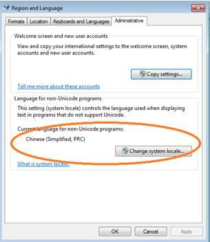
149 143
Revision: 0.30 June Intel Server Board S1200RP UEFI Development Kit Firmware Installation Guide
 Revision: 0.30 June 2016 Intel Server Board S1200RP UEFI Development Kit Firmware Installation Guide Intel Server Board S1200RP UEFI Development Kit Firmware Installation Guide INFORMATION IN THIS DOCUMENT
Intel System Event Log (SEL) Viewer Utility. User Guide SELViewer Version 10.0 /11.0 February 2012 Document number: G
 Viewer Utility. User Guide SELViewer Version 10.0 /11.0 February 2012 Document number: G") Intel System Event Log (SEL) Viewer Utility User Guide SELViewer Version 10.0 /11.0 February 2012 Document number: G24422-003 Legal Statements INFORMATION IN THIS DOCUMENT IS PROVIDED IN CONNECTION WITH
Intel System Event Log (SEL) Viewer Utility User Guide SELViewer Version 10.0 /11.0 February 2012 Document number: G24422-003 Legal Statements INFORMATION IN THIS DOCUMENT IS PROVIDED IN CONNECTION WITH
Revision: 0.30 June Intel Server Board S2600CP4 UEFI Development Kit Firmware Installation Guide
 Revision: 0.30 June 2013 Intel Server Board S2600CP4 UEFI 2.3.1 Development Kit Intel Server Board S2600CP4 UEFI 2.3.1 Development Kit INFORMATION IN THIS DOCUMENT IS PROVIDED IN CONNECTION WITH INTEL
Intel Manycore Platform Software Stack (Intel MPSS)
") Intel Manycore Platform Software Stack (Intel MPSS) README (Windows*) Copyright 2012 2014 Intel Corporation All Rights Reserved Document Number: 328510-001US Revision: 3.4 World Wide Web: http://www.intel.com
Intel Manycore Platform Software Stack (Intel MPSS) README (Windows*) Copyright 2012 2014 Intel Corporation All Rights Reserved Document Number: 328510-001US Revision: 3.4 World Wide Web: http://www.intel.com
Intel Firmware Engine
 Intel Firmware Engine Intel Firmware Engine Application Release 4.0.0 Dec 18, 2017 DISCLAIMER This release note as well as the software described in it is furnished under license and may only be used or
Customizing an Android* OS with Intel Build Tool Suite for Android* v1.1 Process Guide
 Customizing an Android* OS with Intel Build Tool Suite for Android* v1.1 Process Guide May 2015, Revision 1.5 INFORMATION IN THIS DOCUMENT IS PROVIDED IN CONNECTION WITH INTEL PRODUCTS. NO LICENSE, EXPRESS
LED Manager for Intel NUC
 LED Manager for Intel NUC User Guide Version 1.0.0 March 14, 2018 INFORMATION IN THIS DOCUMENT IS PROVIDED IN CONNECTION WITH INTEL PRODUCTS. NO LICENSE, EXPRESS OR IMPLIED, BY ESTOPPEL OR OTHERWISE, TO
Computer Management* (IEA) Training Foils
 Training Foils") Intel-powered classmate PC Computer Management* (IEA) Training Foils Version 1.0 Legal Information INFORMATION IN THIS DOCUMENT IS PROVIDED IN CONNECTION WITH INTEL PRODUCTS. NO LICENSE, EXPRESS OR IMPLIED,
Intel-powered classmate PC Computer Management* (IEA) Training Foils Version 1.0 Legal Information INFORMATION IN THIS DOCUMENT IS PROVIDED IN CONNECTION WITH INTEL PRODUCTS. NO LICENSE, EXPRESS OR IMPLIED,
Intel Platform Innovation Framework for EFI SMBus Host Controller Protocol Specification. Version 0.9 April 1, 2004
 Intel Platform Innovation Framework for EFI SMBus Host Controller Protocol Specification Version 0.9 April 1, 2004 SMBus Host Controller Protocol Specification THIS SPECIFICATION IS PROVIDED "AS IS" WITH
Intel Desktop Board DZ68DB
 Intel Desktop Board DZ68DB Specification Update April 2011 Part Number: G31558-001 The Intel Desktop Board DZ68DB may contain design defects or errors known as errata, which may cause the product to deviate
GUID Partition Table (GPT)
") GUID Partition Table (GPT) How to install an Operating System (OS) using the GUID Disk Partition Table (GPT) on an Intel Hardware RAID (HWR) Array under uefi environment. Revision 1.0 December, 2009 Enterprise
GUID Partition Table (GPT) How to install an Operating System (OS) using the GUID Disk Partition Table (GPT) on an Intel Hardware RAID (HWR) Array under uefi environment. Revision 1.0 December, 2009 Enterprise
Intel Galileo Firmware Updater Tool
 User Guide August 2017 Revision 002 Document Number: 332076-002 Notice: This document contains information on products in the design phase of development. The information here is subject to change without
Introduction to Intel Boot Loader Development Kit (Intel BLDK) Intel SSG/SSD/UEFI
 Intel SSG/SSD/UEFI") Introduction to Intel Boot Loader Development Kit (Intel BLDK) Intel SSG/SSD/UEFI Legal Disclaimer INFORMATION IN THIS DOCUMENT IS PROVIDED IN CONNECTION WITH INTEL PRODUCTS. NO LICENSE, EXPRESS OR IMPLIED,
Introduction to Intel Boot Loader Development Kit (Intel BLDK) Intel SSG/SSD/UEFI Legal Disclaimer INFORMATION IN THIS DOCUMENT IS PROVIDED IN CONNECTION WITH INTEL PRODUCTS. NO LICENSE, EXPRESS OR IMPLIED,
March Getting Started with the Intel Desktop Board DQ77MK UEFI Development Kit
 March 2014 Getting Started with the Intel Desktop Board DQ77MK UEFI 2.3.1 Development Kit Getting Started with the Intel Desktop Board DQ77MK UEFI 2.3.1 Development Kit Legal Information INFORMATION IN
Device Firmware Update (DFU) for Windows
 for Windows") Legal Disclaimer INFORMATION IN THIS DOCUMENT IS PROVIDED IN CONNECTION WITH INTEL PRODUCTS. NO LICENSE, EXPRESS OR IMPLIED, BY ESTOPPEL OR OTHERWISE, TO ANY INTELLECTUAL PROPERTY RIGHTS IS GRANTED BY
Legal Disclaimer INFORMATION IN THIS DOCUMENT IS PROVIDED IN CONNECTION WITH INTEL PRODUCTS. NO LICENSE, EXPRESS OR IMPLIED, BY ESTOPPEL OR OTHERWISE, TO ANY INTELLECTUAL PROPERTY RIGHTS IS GRANTED BY
FW Update Tool. Installation Guide. Software Version 2.2
 FW Update Tool Installation Guide Software Version 2.2 May 24, 2018 i Contents --- Welcome!........................................................................ 1 Key features...................................................................
Mobile Client Capability Brief for Exporting Mail in Microsoft* Office* Outlook* 2007
 Mobile Client Capability Brief for Exporting Mail in Microsoft* Office* Outlook* 2007 http://www.intel.com/performance/resources Version 2008-07 Rev. 1.0 Performance tests and ratings are measured using
Intel Cache Acceleration Software - Workstation
 Intel Cache Acceleration Software - Workstation Version 2.7.0 Order Number: x-009 Contents INFORMATION IN THIS DOCUMENT IS PROVIDED IN CONNECTION WITH INTEL PRODUCTS. NO LICENSE, EXPRESS OR IMPLIED, BY
Best Practices for Configuring the Dell Compellent SMI-S Provider for Microsoft SCVMM 2012
 Dell Compellent Storage Center Best Practices for Configuring the Dell Compellent SMI-S Provider for Microsoft SCVMM 2012 Document Revisions Date Revision Comments 04/11/2012 A First Revision THIS BEST
Intel System Event Log Viewer Utility
 Intel System Event Log Viewer Utility User Guide Reference for using the Intel System Event Log Viewer Utility (SEL Viewer). Rev 1.02 December 2017 Intel Server Products and Solutions Document
DISCLAIMER COPYRIGHT List of Trademarks
 DISCLAIMER This documentation is provided for reference purposes only. While efforts were made to verify the completeness and accuracy of the information contained in this documentation, this documentation
Software Evaluation Guide for WinZip 15.5*
 Software Evaluation Guide for WinZip 15.5* http://www.intel.com/performance/resources Version 2011-06 Rev. 1.1 Information in this document is provided in connection with Intel products. No license, express
Intel Cache Acceleration Software for Windows* Workstation
 Intel Cache Acceleration Software for Windows* Workstation Release 3.1 Release Notes July 8, 2016 Revision 1.3 INFORMATION IN THIS DOCUMENT IS PROVIDED IN CONNECTION WITH INTEL PRODUCTS. NO LICENSE, EXPRESS
Intel Turbo Memory. Release Notes. October Revision
 Intel Turbo Memory Release Notes October 2008 Revision 1.8.0.1018 1B INFORMATION IN THIS DOCUMENT IS PROVIDED IN CONNECTION WITH INTEL PRODUCTS. NO LICENSE, EXPRESS OR IMPLIED, BY ESTOPPEL OR OTHERWISE,
Intel Integrated Native Developer Experience 2015 Build Edition for OS X* Installation Guide and Release Notes
 Intel Integrated Native Developer Experience 2015 Build Edition for OS X* Installation Guide and Release Notes 24 July 2014 Table of Contents 1 Introduction... 2 1.1 Product Contents... 2 1.2 System Requirements...
Software Evaluation Guide for WinZip* esources-performance-documents.html
 Software Evaluation Guide for WinZip* 14 http://www.intel.com/content/www/us/en/benchmarks/r esources-performance-documents.html INFORMATION IN THIS DOCUMENT IS PROVIDED IN CONNECTION WITH INTEL PRODUCTS.
Intel Manageability Commander User Guide
 Intel Manageability Commander User Guide Document Release Date: October 27, 2016 Legal Information INFORMATION IN THIS DOCUMENT IS PROVIDED IN CONNECTION WITH INTEL PRODUCTS. NO LICENSE, EXPRESS OR IMPLIED,
Intel Integrator Toolkit
 Intel Integrator Toolkit User Guide Version 6.1.8 May 4, 2018 INFORMATION IN THIS DOCUMENT IS PROVIDED IN CONNECTION WITH INTEL PRODUCTS. NO LICENSE, EXPRESS OR IMPLIED, BY ESTOPPEL OR OTHERWISE, TO ANY
How to install the software of ZNS8022
 How to install the software of ZNS8022 1. Please connect ZNS8022 to your PC after finished assembly. 2. Insert Installation CD to your CD-ROM drive and initiate the auto-run program. The wizard will run
Intel Core vpro Processors Common-Use Guide
 Intel Core vpro Processors Common-Use Guide For LabTech Software* (Revision 1.1 December 6, 2011) Table of Contents Introduction... 3 Setup and Assumptions... 3 Common Use Cases Covered in this Guide...
PROMISE ARRAY MANAGEMENT ( PAM) FOR FastTrak S150 TX2plus, S150 TX4 and TX4000. User Manual. Version 1.3
 FOR FastTrak S150 TX2plus, S150 TX4 and TX4000. User Manual. Version 1.3") PROMISE ARRAY MANAGEMENT ( PAM) FOR FastTrak S150 TX2plus, S150 TX4 and TX4000 User Manual Version 1.3 Promise Array Management Copyright 2003 Promise Technology, Inc. All Rights Reserved. Copyright by
PROMISE ARRAY MANAGEMENT ( PAM) FOR FastTrak S150 TX2plus, S150 TX4 and TX4000 User Manual Version 1.3 Promise Array Management Copyright 2003 Promise Technology, Inc. All Rights Reserved. Copyright by
How to Create a.cibd File from Mentor Xpedition for HLDRC
 How to Create a.cibd File from Mentor Xpedition for HLDRC White Paper May 2015 Document Number: 052889-1.0 INFORMATION IN THIS DOCUMENT IS PROVIDED IN CONNECTION WITH INTEL PRODUCTS. NO LICENSE, EXPRESS
Dell Repository Manager Business Client Version 2.0 User s Guide
 Dell Repository Manager Business Client Version 2.0 User s Guide Notes, Cautions, and Warnings NOTE: A NOTE indicates important information that helps you make better use of your computer. CAUTION: A CAUTION
Intel Server RAID Controller U2-1 Integration Guide For Microsoft* Windows NT* 4.0
 Intel Server RAID Controller U2-1 Integration Guide For Microsoft* Windows NT* 4.0 Revision 1.0 February 2000 Revision History Revision Revision History Date 1.0 Initial Release 02/10/00 Intel Corporation
Boot Agent Application Notes for BIOS Engineers
 Boot Agent Application Notes for BIOS Engineers September 2007 318275-001 Revision 1.0 Legal Lines and Disclaimers INFORMATION IN THIS DOCUMENT IS PROVIDED IN CONNECTION WITH INTEL PRODUCTS. NO LICENSE,
Intel Desktop Board DH55TC
 Intel Desktop Board DH55TC Specification Update December 2011 Order Number: E88213-006 The Intel Desktop Board DH55TC may contain design defects or errors known as errata, which may cause the product to
Intelligent Tiered Storage Acceleration Software for Windows 10
 for Windows 10 QUICK START GUIDE April 2018 2018 Advanced Micro Devices, Inc. All rights reserved. AMD, the AMD logo, Ryzen, Threadripper, and combinations thereof are trademarks are of Advanced Micro
SC-T35/SC-T45/SC-T46/SC-T47 ViewSonic Device Manager User Guide
 SC-T35/SC-T45/SC-T46/SC-T47 ViewSonic Device Manager User Guide Copyright and Trademark Statements 2014 ViewSonic Computer Corp. All rights reserved. This document contains proprietary information that
Installation Guide and Release Notes
 Installation Guide and Release Notes Document number: 321604-002US 9 July 2010 Table of Contents 1 Introduction... 1 1.1 Product Contents... 2 1.2 What s New... 2 1.3 System Requirements... 2 1.4 Documentation...
Intel Unite Solution Intel Unite Plugin for WebEx*
 Intel Unite Solution Intel Unite Plugin for WebEx* Version 1.0 Legal Notices and Disclaimers All information provided here is subject to change without notice. Contact your Intel representative to obtain
Intel Solid State Drive Firmware Update Tool
 Intel Solid State Drive Firmware Update Tool Software Version 3.0.0 or later Document Number: 322570-011US Intel disclaims all express and implied warranties, including without limitation, the implied
INTEL PERCEPTUAL COMPUTING SDK. How To Use the Privacy Notification Tool
 INTEL PERCEPTUAL COMPUTING SDK How To Use the Privacy Notification Tool LEGAL DISCLAIMER THIS DOCUMENT CONTAINS INFORMATION ON PRODUCTS IN THE DESIGN PHASE OF DEVELOPMENT. INFORMATION IN THIS DOCUMENT
Intel Desktop Board DP55SB
 Intel Desktop Board DP55SB Specification Update July 2010 Order Number: E81107-003US The Intel Desktop Board DP55SB may contain design defects or errors known as errata, which may cause the product to
Palm Reader Handbook
 Palm Reader Handbook Copyright 2000-2002 Palm, Inc. All rights reserved. Graffiti, HotSync, the Palm logo, and Palm OS are registered trademarks of Palm, Inc. The HotSync logo and Palm are trademarks of
Software Evaluation Guide for Photodex* ProShow Gold* 3.2
 Software Evaluation Guide for Photodex* ProShow Gold* 3.2 http://www.intel.com/performance/resources Version 2007-12 Rev. 1.0 Information in this document is provided in connection with Intel products.
IBM Client Security Solutions. Client Security Software Version 1.0 Administrator's Guide
 IBM Client Security Solutions Client Security Software Version 1.0 Administrator's Guide December 1999 1 Before using this information and the product it supports, be sure to read Appendix A - U.S. export
How to Create a.cibd/.cce File from Mentor Xpedition for HLDRC
 How to Create a.cibd/.cce File from Mentor Xpedition for HLDRC White Paper August 2017 Document Number: 052889-1.2 INFORMATION IN THIS DOCUMENT IS PROVIDED IN CONNECTION WITH INTEL PRODUCTS. NO LICENSE,
Authentication Services ActiveRoles Integration Pack 2.1.x. Administration Guide
 Authentication Services ActiveRoles Integration Pack 2.1.x Administration Guide Copyright 2017 One Identity LLC. ALL RIGHTS RESERVED. This guide contains proprietary information protected by copyright.
Software Evaluation Guide for ImTOO* YouTube* to ipod* Converter Downloading YouTube videos to your ipod
 Software Evaluation Guide for ImTOO* YouTube* to ipod* Converter Downloading YouTube videos to your ipod http://www.intel.com/performance/resources Version 2008-09 Rev. 1.0 Information in this document
Installation Guide and Release Notes
 Installation Guide and Release Notes Document number: 321604-001US 19 October 2009 Table of Contents 1 Introduction... 1 1.1 Product Contents... 1 1.2 System Requirements... 2 1.3 Documentation... 3 1.4
Intel Desktop Board D845PT Specification Update
 Intel Desktop Board D845PT Specification Update Release Date: February 2002 Order Number: A83341-002 The Intel Desktop Board D845PT may contain design defects or errors known as errata which may cause
Intel Entry Storage System SS4000-E
 Intel Entry Storage System SS4000-E Software Release Notes January 2007 Storage Systems Technical Marketing Engineering Document Revision History Intel Entry Storage System SS4000-E Document Revision History
Dell Repository Manager Business Client Version 2.1 User s Guide
 Dell Repository Manager Business Client Version 2.1 User s Guide Notes, cautions, and warnings NOTE: A NOTE indicates important information that helps you make better use of your computer. CAUTION: A CAUTION
NET+Works with GNU Tools Tutorial
 NET+Works with GNU Tools Tutorial NET+Works with GNU Tools Tutorial Operating system/version: 6.2 Part number/version: 90000697_B Release date: April 2005 www.netsilicon.com 2001-2005 NetSilicon, Inc.Printed
PROMISE ARRAY MANAGEMENT ( PAM) USER MANUAL
 USER MANUAL") PROMISE ARRAY MANAGEMENT ( PAM) USER MANUAL Copyright 2002, Promise Technology, Inc. Copyright by Promise Technology, Inc. (Promise Technology). No part of this manual may be reproduced or transmitted
PROMISE ARRAY MANAGEMENT ( PAM) USER MANUAL Copyright 2002, Promise Technology, Inc. Copyright by Promise Technology, Inc. (Promise Technology). No part of this manual may be reproduced or transmitted
1. Save the Express BIOS update file to a temporary directory on the target PC. 2. Double-click the *.EXE file to run the Express BIOS update.
 BIOS Update Readme BIOS Update Instructions for Intel Desktop Boards This Readme file includes BIOS update instructions for advanced users. If you need more complete step-by-step instructions on how to
SafeNet Authentication Client
 SafeNet Authentication Client Integration Guide All information herein is either public information or is the property of and owned solely by Gemalto NV and/or its subsidiaries who shall have and keep
Intel G31/P31 Express Chipset
 Intel G31/P31 Express Chipset Specification Update For the Intel 82G31 Graphics and Memory Controller Hub (GMCH) and Intel 82GP31 Memory Controller Hub (MCH) February 2008 Notice: The Intel G31/P31 Express
DS800 Development Suite Quick Start Guide for the FloBoss 107
 Form A6267 Part Number D301597X012 January 2009 DS800 Development Suite Quick Start Guide for the FloBoss 107 Version 1.0 Remote Automation Solutions Revision Tracking Sheet January 2009 This manual may
Installing AppleWorks 6 FOR WINDOWS
 apple Installing AppleWorks 6 FOR WINDOWS 1 Installing AppleWorks 6 This booklet provides instructions for m installing and uninstalling AppleWorks m setting up an AppleWorks Installer on a server, so
Intel Integrated Native Developer Experience 2015 Build Edition for OS X* Installation Guide and Release Notes
 Intel Integrated Native Developer Experience 2015 Build Edition for OS X* Installation Guide and Release Notes 22 January 2015 Table of Contents 1 Introduction... 2 1.1 Change History... 2 1.1.1 Changes
A Tour Beyond BIOS Using the Intel Firmware Support Package with the EFI Developer Kit II
 White Paper A Tour Beyond BIOS Using the Intel Firmware Support Package with the EFI Developer Kit II Jiewen Yao Intel Corporation Vincent J. Zimmer Intel Corporation Ravi Rangarajan Intel Corporation
Intel IoT Gateway Platform Data Editor Tool
 Intel IoT Gateway Platform Data Editor Tool Order No.: 332180-002 By using this document, in addition to any agreements you have with Intel, you accept the terms set forth below. You may not use or facilitate
Dell Repository Manager Business Client Version 2.2 User s Guide
 Dell Repository Manager Business Client Version 2.2 User s Guide Notes, cautions, and warnings NOTE: A NOTE indicates important information that helps you make better use of your computer. CAUTION: A CAUTION
Intel Desktop Board D945GCLF2
 Intel Desktop Board D945GCLF2 Specification Update July 2010 Order Number: E54886-006US The Intel Desktop Board D945GCLF2 may contain design defects or errors known as errata, which may cause the product
SSD Utility. Installation Guide. Software Version 3.n
 SSD Utility Installation Guide Software Version 3.n Contents Welcome!............................................................................. 1 Key features.........................................................................
Clear CMOS after Hardware Configuration Changes
 Clear CMOS after Hardware Configuration Changes Technical White Paper August 2018 Revision 001 Document Number: 337986-001 You may not use or facilitate the use of this document in connection with any
Intel 945(GM/GME)/915(GM/GME)/ 855(GM/GME)/852(GM/GME) Chipsets VGA Port Always Enabled Hardware Workaround
/915(GM/GME)/ 855(GM/GME)/852(GM/GME) Chipsets VGA Port Always Enabled Hardware Workaround") Intel 945(GM/GME)/915(GM/GME)/ 855(GM/GME)/852(GM/GME) Chipsets VGA Port Always Enabled Hardware Workaround White Paper June 2007 Order Number: 12608-002EN INFORMATION IN THIS DOCUMENT IS PROVIDED IN CONNECTION
Intel 945(GM/GME)/915(GM/GME)/ 855(GM/GME)/852(GM/GME) Chipsets VGA Port Always Enabled Hardware Workaround White Paper June 2007 Order Number: 12608-002EN INFORMATION IN THIS DOCUMENT IS PROVIDED IN CONNECTION
The Intel SSD Pro 2500 Series Guide for Microsoft edrive* Activation
 The Intel SSD Pro 2500 Series Guide for Microsoft edrive* Activation Solutions Blueprint January 2015 Order Number: 330880-002US INFORMATION IN THIS DOCUMENT IS PROVIDED IN CONNECTION WITH INTEL PRODUCTS.
Intel Dynamic Platform and Thermal Framework (Intel DPTF), Client Version 8.X
, Client Version 8.X") Intel Dynamic Platform and Thermal Framework (Intel DPTF), Client Version 8.X 8.1.10300.137 PV Release Release Notes March 2015 1 INFORMATION IN THIS DOCUMENT IS PROVIDED IN CONNECTION WITH INTEL PRODUCTS.
Intel Dynamic Platform and Thermal Framework (Intel DPTF), Client Version 8.X 8.1.10300.137 PV Release Release Notes March 2015 1 INFORMATION IN THIS DOCUMENT IS PROVIDED IN CONNECTION WITH INTEL PRODUCTS.
LiteSpeed for SQL Server 6.1. Configure Log Shipping
 LiteSpeed for SQL Server 6.1 Configure Log Shipping 2010 Quest Software, Inc. ALL RIGHTS RESERVED. This guide contains proprietary information protected by copyright. The software described in this guide
Microsoft Office Groove Server Groove Manager. Domain Administrator s Guide
 Microsoft Office Groove Server 2007 Groove Manager Domain Administrator s Guide Copyright Information in this document, including URL and other Internet Web site references, is subject to change without
ACE Operation Manual
 ACE Operation Manual Elecsys Director ACE Operation Manual Product Information Full information about other Elecsys products is available on our website at www.elecsyscorp.com Useful Contact Information
Reference Boot Loader from Intel
 Document Number: 328739-001 Introduction INFORMATION IN THIS DOCUMENT IS PROVIDED IN CONNECTION WITH INTEL PRODUCTS. NO LICENSE, EXPRESS OR IMPLIED, BY ESTOPPEL OR OTHERWISE, TO ANY INTELLECTUAL PROPERTY
Intel Desktop Board DH61CR
 Intel Desktop Board DH61CR Specification Update December 2011 Order Number: G27744-003 The Intel Desktop Board DH61CR may contain design defects or errors known as errata, which may cause the product to
SonicWall Global VPN Client Getting Started Guide
 SonicWall Global VPN Client 4.10 Getting Started Guide Copyright 2017 SonicWall Inc. All rights reserved. SonicWall is a trademark or registered trademark of SonicWall Inc. and/or its affiliates in the
Intel Desktop Board DQ35JO
 Intel Desktop Board DQ35JO Specification Update July 2010 Order Number: E21492-005US The Intel Desktop Board DQ35JO may contain design defects or errors known as errata, which may cause the product to
Manuals for This Product
 Installation Guide Manuals for This Product The manuals for this product are structured as indicated below. Read the manuals that meet your objective to make full use of this product. Disc Manuals with
Enhanced Serial Peripheral Interface (espi) ECN
 ECN") Enhanced Serial Peripheral Interface (espi) ECN Engineering Change Notice TITLE Clarify OOB packet payload DATE 10 January 2014 AFFECTED DOCUMENT espi Base Specification Rev 0.75 DISCLOSURE RESTRICTIONS
Enhanced Serial Peripheral Interface (espi) ECN Engineering Change Notice TITLE Clarify OOB packet payload DATE 10 January 2014 AFFECTED DOCUMENT espi Base Specification Rev 0.75 DISCLOSURE RESTRICTIONS
Lenovo XClarity Provisioning Manager User Guide
 Lenovo XClarity Provisioning Manager User Guide Fifth Edition (October 2018) Copyright Lenovo 2017, 2018. LIMITED AND RESTRICTED RIGHTS NOTICE: If data or software is delivered pursuant to a General Services
Perceptive TransForm E-Forms Manager
 Perceptive TransForm E-Forms Manager Installation and Setup Guide Version: 8.x Date: February 2017 2016-2017 Lexmark. All rights reserved. Lexmark is a trademark of Lexmark International Inc., registered
FaxFinder Fax Servers
 FaxFinder Fax Servers Models: FF130 FF230 FF430 FF830 Client User Guide FaxFinder Client User Guide Fax Client Software for FaxFinder Series PN S000460B, Version B Copyright This publication may not be
Intel Integrated Native Developer Experience 2015 (OS X* host)
") Intel Integrated Native Developer Experience 2015 (OS X* host) Release Notes and Installation Guide 24 September 2014 Intended Audience Software developers interested in a cross-platform productivity suite
Intel Integrated Native Developer Experience 2015 (OS X* host) Release Notes and Installation Guide 24 September 2014 Intended Audience Software developers interested in a cross-platform productivity suite
AMD NVMe/SATA RAID Quick Start Guide for Windows Operating Systems
 AMD NVMe/SATA RAID Quick Start Guide for Windows Operating Systems Publication # 56268 Revision: 1.02 Issue Date: April 2018 Advanced Micro Devices 2018 Advanced Micro Devices, Inc. All rights reserved.
Intel Desktop Board DQ57TM
 Intel Desktop Board DQ57TM Specification Update December 2010 Order Number: E88215-006US The Intel Desktop Board DQ57TM may contain design defects or errors known as errata, which may cause the product
VERITAS NetBackup 6.0 for Microsoft SharePoint Portal Server 2001
 VERITAS NetBackup 6.0 for Microsoft SharePoint Portal Server 2001 System Administrator s Guide for Windows N152708 September 2005 Disclaimer The information contained in this publication is subject to
Cisco C880 M4 Server User Interface Operating Instructions for Servers with E v2 and E v3 CPUs
 Cisco C880 M4 Server User Interface Operating Instructions for Servers with E7-8800 v2 and E7-8800 v3 CPUs November, 2015 THE SPECIFICATIONS AND INFORMATION REGARDING THE PRODUCTS IN THIS MANUAL ARE SUBJECT
OmniPass 2.0 User's Guide. Version 1.2
 OmniPass 2.0 User's Guide Version 1.2 i Copyright Copyright 2002 Softex Incorporated. No part of this publication may be reproduced, transmitted, transcribed, stored in a retrieval system, or translated
Disassemble the machine code present in any memory region. Single step through each assembly language instruction in the Nios II application.
 Nios II Debug Client This tutorial presents an introduction to the Nios II Debug Client, which is used to compile, assemble, download and debug programs for Altera s Nios II processor. This tutorial presents
Intel Unite Solution Intel Unite Plugin for Ultrasonic Join
 Intel Unite Solution Intel Unite Plugin for Ultrasonic Join Version 1.0 March 2018 Legal Disclaimers & Copyrights All information provided here is subject to change without notice. Contact your Intel representative
Intel Atom Processor E3800 Product Family Development Kit Based on Intel Intelligent System Extended (ISX) Form Factor Reference Design
 Form Factor Reference Design") Intel Atom Processor E3800 Product Family Development Kit Based on Intel Intelligent System Extended (ISX) Form Factor Reference Design Quick Start Guide March 2014 Document Number: 330217-002 Legal Lines
Intel Atom Processor E3800 Product Family Development Kit Based on Intel Intelligent System Extended (ISX) Form Factor Reference Design Quick Start Guide March 2014 Document Number: 330217-002 Legal Lines
Nimsoft Service Desk. Single Sign-On Configuration Guide. [assign the version number for your book]
![Nimsoft Service Desk. Single Sign-On Configuration Guide. [assign the version number for your book]](/thumbs/80/81218109.jpg "Nimsoft Service Desk. Single Sign-On Configuration Guide. [assign the version number for your book]") Nimsoft Service Desk Single Sign-On Configuration Guide [assign the version number for your book] Legal Notices Copyright 2012, CA. All rights reserved. Warranty The material contained in this document
Nimsoft Service Desk Single Sign-On Configuration Guide [assign the version number for your book] Legal Notices Copyright 2012, CA. All rights reserved. Warranty The material contained in this document
Open-E Data Storage Server. Intel Modular Server
 Open-E Data Storage Server Intel Modular Server Contents About Open-E Data Storage Server*...4 Hardware Components...5 Installation Software...6 Open-E Data Storage Server* Installation...7 2 www.intel.com/go/esaa
1.0. Quest Enterprise Reporter Discovery Manager USER GUIDE
 1.0 Quest Enterprise Reporter Discovery Manager USER GUIDE 2012 Quest Software. ALL RIGHTS RESERVED. This guide contains proprietary information protected by copyright. The software described in this guide
User Guide. Micron NAND Flash Simulator (NSIM)
") Introduction User Guide Micron NAND Flash Simulator (NSIM) Introduction Nonvolatile NAND Flash memory devices are high data throughput devices that permanently store data or code. This capability is ideal
Introduction User Guide Micron NAND Flash Simulator (NSIM) Introduction Nonvolatile NAND Flash memory devices are high data throughput devices that permanently store data or code. This capability is ideal
HP Video Over Ethernet. User Guide
 HP Video Over Ethernet User Guide 2016 HP Development Company, L.P. The information contained herein is subject to change without notice. The only warranties for HP products and services are set forth
YubiHSM 2 for ADCS Guide. Securing Microsoft Active Directory Certificate Services with YubiHSM 2
 YubiHSM 2 for ADCS Guide Securing Microsoft Active Directory Certificate Services with YubiHSM 2 Copyright 2017 Yubico Inc. All rights reserved. Trademarks Yubico and YubiKey are registered trademarks
DCMI Data Center Manageability Interface Specification v1.0, Revision 1.0. Addenda, Errata, and Clarifications
 DCMI Data Center Manageability Interface Specification v1.0, Revision 1.0 Addenda, Errata, and Clarifications Addendum Document Revision 1 Date: 4/21/2009 THIS SPECIFICATION IS PROVIDED "AS IS" WITH NO
No: SW1.12_4.0.2 V F
 Jupiter-F 2 User s Manual 2010 Navman Wireless OEM. All Rights Reserved. SiRF and SiRF logo are registered trademarks of SiRF Technology, Inc. SiRFstar, SiRFLoc, Push-to-Fix, and Trickle-Power are trademarks
Image Backup and Recovery Procedures For Windows 7
 Image Backup and Recovery Procedures For Windows 7 Thank you for purchasing a Fujitsu computer. Fujitsu is committed to bringing you the best computing experience with your new system. It is very important