NVMS-7000 Client Software User Manual Version 1.03
|
|
|
- Walter Cox
- 6 years ago
- Views:
Transcription
1 NVMS-7000 Client Software User Manual Version 1.03
2 Contents Chapter 1. Overview Description Running Environment... 3 Chapter 2. Starting NVMS User Registration Wizard for Importing Device User Login Control Panel and Main Menu Bar Introduction Account Management Chapter 3. Connecting and Local Management for DVR, NVR and Network Cameras Device Adding in the Device Management Interface Adding Device Device Configuration Adding a Camera Group Live View Basic Operations in Live View Capture in Live View PTZ Control in Live View Alarm and Event in Live View View Alarm /Event Information Alarm Log Linkage Block the Alarm from Certain Device Local Recording and Capture Recording and Picture Capturing on the host PC for the NVMS Local Playback Playback of Local Stored Files Instant Playback E-map Management Adding a E-map The Hot Spot Function The Hot Region Function Chapter 4. Remote Control and Management for DVR, NVR and Network Cameras Remote Recording Recording on the Storage Device on the DVR, NVR or Network Camera Recording on the Storage Server(PC NVR) Remote Playback Remote Device Management and Configuration Basic Information General Settings Camera Management Network Settings Alarm Settings User Management HDD Settings Exception Settings File Management Log Management Holiday Settings Other Settings (RS-232 Settings and Remote Upgrade) Channel-zero Settings Resource Usage... 66
3 4.4 Camera Settings Picture Settings Video Quality Record Schedule Video Display Motion Detection Tampering Alarm Video Loss Detection PTZ Parameters Settings Network Connection Chapter 5. Forwarding Video Stream from Stream Media Server Adding a Stream Media Server Forwarding Video Stream via the Stream Media Server Chapter 6. Decoding Video Stream and Displaying the Video on TV Wall Adding Decoding Device Editing TV Wall Display Videos on the TV Wall PC Decoder Chapter 7. Log Management Local Log Search Log Backup Opening Log Files Chapter 8. System Configuration General Configuration File Saving Path Configuration Alarm Sound Configuration Configuration Chapter 9. FAQ Live View Recording Playback... 92
4 Chapter 1. Overview 1.1 Description NVMS-7000 is a video management software using a distributed structure to provide centralized management for all the connectable devices. It can manage the NVR, DVR, IP cameras, compression card and decoders. With different management and configuration modules and a reasonable collocation, it provides many solutions for different surveillance scenario, medium or small scale. It is a steady and reliable system with functions like real-time monitoring, video recording and searching, file backup, TV wall displaying, etc. This user manual describes the function, configuration and operation steps of NVMS-7000 software. To ensure the properness and stability of the software, please refer to the contents below and read the manual carefully before installation and operation. 1.2 Running Environment Operating system: Microsoft Windows 7/Windows 2008(32/64 bit operating system), Windows 2003/2000/Windows XP(32 bit operating system) CPU:Intel Pentium IV 3.0 GHz or above Memory:1G or above Display: 1024*768 or above Note: To simultaneously live view for many channels, or for the channel with high resolution, the higher hardware configuration is needed. The software does not support 64 bit operating system; the above mentioned 64 bit operating system refers to the system which supports 32 bit operating system as well.

5 Chapter 2. Starting NVMS User Registration For the first time to use the NVMS-7000 software, you need to register a super user for login. Enter the super user name, password and confirm the password in the dialog box and click Register. Then, you can log in as the super user. Note: Enter, Space, and TAB keys are invalid for the user name and password. The password cannot be empty, and it should not be less than six characters and can t be copied and pasted. 2.2 Wizard for Importing Device Purpose: The main function of the NVMS-7000 is to manage network devices remotely. Thus the task on the top hierarchy is to register the device to the management list. For the first time user, the wizard message box pops up to ask you whether you want to be guided for the basic operation of the client software.

6 If this is not the first time you use the client software, the wizard doesn t pop up, and you can also use the wizard, click Help and Open Wizard. Click to start the wizard, or click Cancel to exit the wizard. Steps: 1. According to the hint, click Add icon to add devices to the management list of the software. 2. Create a nickname for the device, enter the IP address and the port number of the remote device, enter the user name, and the password of the device. 3. Click Add icon to add the device.
7 If you add the device with a domain name, you can check the Private Domain Mode checkbox. And create a nickname, enter the domain name and port number, and enter the admin name and password of the device to add the device. You can also click Show online device to show the device connected to the same Local Area Network. Adding the active online devices Steps: 1) Select the device in the device list, and the information of the device such as the MAC address the software version and the serial number is shown in the left part. The information in this part can t be modified. 2) In the Network information area, you can modify the IP address the Subnet Mask and the Port number with entering the admin password of the device. 3) You can also recover the default password for the device, with the code provided by the authorized engineers.


8 4. Adding Camera Group When adding a device, you can check the Export to group checkbox to export the device you added to certain camera group. By default, the name of the group is the same with the name of the device you just added. If you want you customize the camera choosing for the group and the group name. You uncheck the Export to Group checkbox and click Next page on the Wizard, to enter the adding group interface. Click Save to add a new user. Click Modify to change the settings for the new user. 5. Click the on Group dialog box. Edit the name of group and then click OK to save your settings. The added group will be displayed in the list.

9 6. Import Channels to Group In the left area on the Camera Import interface, click to select the channels and then click Import button to import the selected channels to the Group on the right. 7. You can drag and select multiple channels to import them to the group you added. Note:

10 The devices to be added must be online currently. One channel can be added to different groups. Up to 256 groups can be added, and 64 channels can be added to each group, with a maximum of 1024 channels for all the groups totally. After importing the selected channels to the group, you can return to the control panel and then enter the Main View interface to get a live view of the added channels. 2.3 User Login When you open the NVMS-7000 software after registration, the login dialog box pops up, shown in the following figure: Input the user name and password, and then click Login. Check the Enable Auto-login checkbox to enable auto-login,and then the user name and password is not needed for the login next time.
 and view the captured pictures.")
11 2.4 Control Panel and Main Menu Bar Introduction The main control panel of the NVMS-7000 is shown in the following figure: Menu Bar: File System View Open Captured Picture: Enter the setting interface to browse the folder in the host PC of the exported captured picture file (s) and view the captured pictures. Open the video player and browse the folder location of the exported video file (s), click Open Video File: to browse the folder in the host PC of the record files. You can also capture pictures during the playing of the video file. Open Log File: Enter the Log File interface to browse in the host PC of the folder location of the exported log file(s). Exit: Exit the NVMS-7000 remote client. Lock: Lock the screen operation. You must log in after locking the system. Switch User: Switch login user. System Configuration: Enter the System Configuration interface. Import Configuration Import client configuration file from your computer. File: Export Configuration Export client configuration file to your computer. File: 1024*768: Display window at size of 1024* *1024: Display window at size of 1280*1024. Full Screen: Display window in full screen. Control Panel: Enter Control Panel. Main View: Enter Main View interface. E-map: Enter E-map interface. Event Search: Enter Event Search interface. TV Wall: Enter TV Wall Setting interface.
12 Import Camera Enter Import Camera interface. Camera Settings Enter Camera Setting interface. Account Management Enter User Account Management interface. Device Management Enter Device Management interface. Tools Storage Server Enter Storage Server Management interface. Management Stream Media Server Enter Stream Media Server Management interface. Management Decoding Device Enter Decoding Device Management interface. Management Broadcast Select device to start broadcasting. Help Open Wizard Use the guide for camera import. About View information of the client software, including company, software name, version, etc. User Manual (F1) Click to open the User Manual; you can also open the User Manual by pressing FI on your keyboard. There are 14 icons on the control panel, and their functions are described in the following table: Operating Options Management Options Main View E-map Event Search Remote Playback TV Wall Import Camera Local Log Search Account Management Device Management Storage Server Management Stream Media Server Viewing live and playback video; realize video operation (e.g., picture capture, recording, PTZ control, etc.). Managing and displaying E-Map and hot areas and spots; realize E-Map operation (e.g., operate map zoom in/out, view hot spot, display alarm, etc.) Searching and playback of the event record files; realize playback operation. Playback the recorded video and/or audio files in the remote client. Configuring the decoding of the channels and show them on the TV wall. Adding, modifying or removing the camera groups; import/export of cameras. Searching, viewing and backup of local logs (alarm, operation, system logs). Adding, modifying or removing the user account parameters; assign operating permission to each user. Adding, modifying or removing the DVR device; configuring parameters (e.g., network, alarm input/output, HDD, etc.) for the added DVR. Adding, modifying or removing the storage server; configuring parameters (e.g., record schedule, network, HDD, etc.) for the added storage server. Adding, modifying or removing the stream media server; configuring parameters (e.g., RTSP port, upper/lower limit, etc.) for the added stream media server.
13 Decoding Device TV Wall Management Adding, modifying or removing the decoder; configuring parameters (e.g., network, alarm input/output, exception, etc.) for the added decoder. Adding, modifying and deleting the TV wall. Configuration Options Camera Settings Configuring camera parameters (e.g., image quality, record schedule, motion detection, etc.). System Configuration Configuring the general parameters (e.g., saving path of files, alarm sound, , etc.).

14 2.5 Account Management Purpose: In the NVMS-7000 client software, many user accounts can be added, and for the different users, different permissions can be granted. Steps: 1. Click to enter the account management interface: 2. Click Add to enter the popup Add User dialog box as follows: User Information: User Type: you can select in the dropdown list the two kinds of user types (Administrator and Operator) to create the users with different permissions. User Name &Password: Customize the login user name and password.
15 User Permissions There are 27 operating permissions to be selected and the permission to access to different cameras is also provided. Note: The Admin user has all the permissions as default and operator user s permission should be selected in the list. All the selected permissions take effect immediately.
16 Chapter 3. Connecting and Local Management for DVR, NVR and Network Cameras Before any operation, you need to add a device and import cameras. There are many ways to add the device in the management list. You can add devices follow the guide of wizard. Please refer to Section 2.2 Wizard for Importing Device. This chapter introduces the connecting and management of the devices. 3.1 Device Adding in the Device Management Interface Adding Device Steps: 1. Click to enter the device management interface. 2. Click Add in the Device Management interface. 3. Create a nickname for the device and then input it with other information, the User Name and Password are admin and respectively and the port number is 8000 by default.
17 If you check the Private Domain Mode checkbox, you should input the DNS address and Device ID as well. The NVMS-7000 also provides the searching the active online devices function. Steps: 1. Click the Show Online Devices icon to search the online devices. All the online devices will be searched and shown on the interface. 2. Click to select the online devices you want to add, and then click Select Device to add the device. 3. Enter the nickname, the user name and the password of the device to add it to the management list.


18 Index shows the numbers of the devices found. Be Added status shows the adding status of the device, if the device is already added in the management list of the software, Yes is shown in this list. Device type shows the type of the device, whether it is a camera or a DVR and so on. Steps: 1. Select the device in the device list, and the information of the device such as the MAC address the software version and the serial number is shown in the left part. The information in this part can t be modified. 2. In the Network information area, you can modify the IP address the Subnet Mask and the Port number with entering the admin password of the device. 3. You can also recover the default password for the device, with the code provided by the authorized engineers Device Configuration After adding the device, you can follow the procedure in this section to configure the device. 1. Click the device name to select the device in the Device Management interface.

19 2. You can click to edit the device basic information as device name and address. Or You also can double click the device to modify it. Click icon to delete the selected device and you can also configure the settings of the device by clicking. For the detailed procedures of remote configuration, please refer to 4.3 Remote Device 4.3 Remote Device Management and Configuration. 3.2 Adding a Camera Group A camera group must be added for the live view and other operation. After adding the device, please return to the control panel interface and click to enter camera group configuration interface. Steps: 1. Click Add to create a group in the right area. 2. Select the camera in the left area, and then click or to add the cameras to the group. You can also hold the Ctrl key and select multiple channels or drag and select the channels to import.


20 3.3 Live View Before you start: A camera group is required to be defined before live view. For the grouping operation, please refer to chapter 3.2 Adding a Camera Group. And the group name is shown on the list in the left bar. Entering the Live View Interface: Click the main view icon on the control panel, or click View -> Main View on the toolbar to enter the live view interface. The main view interface is shown in the following figure:

21 Camera Status: Icon Description Camera is online and works properly. Camera is offline. Camera is in live view. Camera is in recording status. Main View Toolbar: Button Name Description Layout Select different layout mode. Full Screen Stop All Manual Record Previous and Next Auto Switch Volume Live Audio Display video in full screen mode, click again to restore. Stop the display of all the cameras. Start manual record for the selected channel, click again to stop. Click to view previous and next camera. Start auto switching the screen by cameras or by groups. Adjust the volume for live audio. Enable/disable live audio. Click, the following box pops up, you can choose the screen layout by clicking certain icon.


22 3.3.1 Basic Operations in Live View Start live view for one channel: To view the live video, drag the camera from the list to the display window, or double click the camera name after you select one screen. Start live view for camera group: You can also get the live view for the whole group to display the live view of the cameras in the group in the screen. Click on the group name, and then click the Play button at the bottom of the screen, see the following figure. Or Double click the group name. Toolbar in each display window: Button Description Capture Start manual record, click it again to stop

23 Stop live view: Start voice talk, click again to stop. This two-way audio can be used for only one camera at one time. When you enable the voice talk of one camera, then the voice talk for other camera is stopped. PTZ control, 8 direction icons will be displayed on the video. Check the camera status Go to the camera setting interface Stop live view Remote playback about 7 minutes record of current camera Audio button, click to open and close To stop the live view for one channel, you can click To stop the live view for all the channels, click in the quick setting toolbar. on the bottom bar. Cycle Live View: Cycle live view mode includes the auto-switch in one screen or the auto-switch in multi-screen. 1. Click the next to the. 2. Choose the auto-switch mode and set the interval for the switching. 3. Click on the toolbar on the bottom to start the cycle live view Capture in Live View Steps: 1. Select the screen. 2. Click icon on the bottom toolbar of Main View, or click icon in the tool bar of this display window.


24 A small window of the captured picture will be displayed to notify you whether the capture is done or not. If the capture is successful, there will be a link to the saving path of the pictures, and if not, there will be error messages accordingly. To view the captured pictures: Click on the small window of the pictures showed on the right bottom after capture. Click the icon on the left toolbar; all the pictures captured on the remote client are stored here. Click File button on the toolbar and select Open Captured File PTZ Control in Live View For the PTZ control, click the icon on the toolbar on the screen for each camera, and the PTZ control panel will be displayed on the left side of the Main View. Note: This chapter only shows the operation of the PTZ control, to configure the PTZ parameters see PTZ


25 Click on those directional buttons to control the PTZ function, or click the directional buttons on the PTZ control panel. You can also control the PTZ direction by the directional buttons on your keyboard. You can control PTZ by dragging and clicking the mouse on the display screen window. Use the mouse to click on the video image, and then drag the mouse to different directions by following the arrows displayed on the video: Upper Left; Up; Upper Right; Left; Right; Lower Right; Down; Lower Right. The PTZ will move to the direction as the arrow goes. Description of buttons on PTZ Control Panel: Button Zoom Focus Iris 3D Positioning Light Wiper Description

26 Directional buttons, click to start/stop auto-scan. Speed adjustment for PT function Preset configuration Pattern configuration Patrol configuration Calling function Adding and editing function Deleting Preset Configuration To add a preset for the PTZ: Steps: 1. Click the directional buttons to move the PTZ to a desired location, 2. Select a PTZ preset number from the preset list, and then click to add the preset and name this PTZ preset. To delete a preset, select the PTZ preset from the preset list, and then click to remove it. Pattern Configuration To add a pattern for the PTZ, Steps: 1. Click the button to enter the PTZ pattern path setup panel. 2. Select a PTZ pattern path number from the pattern list, click to enter edit mode. 3. Click to start recording of this pattern path. 4. Use the directional buttons to control the PTZ movement. 5. Click to stop the pattern recording. Click to save the pattern path.

 for this patrol")

27 Patrol Configuration After adding two or more presets for one channel, you can set a patrol with presets for PTZ. To add a patrol path for the PTZ: Steps: 1. Click the button to enter the PTZ patrol path setup panel. 2. Select a track number from the list. 3. Click to add a preset (including the dwell time and PTZ speed for the preset) for this patrol path. 4. Click to call the patrol path or click to stop calling. 5. Click to edit a preset in the patrol path. Notes: Up to 16 patrols can be configured. The patrol time can be set to 1~255 sec, and the patrol speed to level 1~40.


28 Repeat the above operation to add other presets to the patrol. After configuration, you can choose the patrol from the drop-down list clicking or key., and then call or stop them by 3.4 Alarm and Event in Live View View Alarm /Event Information The Main View interface provides the buttons at the left bottom toolbar. Click the button to view the alarm or event information as shown in the panel. You can click icon to lock the toolbar and show the information in the main view. Or click to hide the list. Click icon to maximize the alarm/event log display panel and enable it to be shown in a new tab page.


29 As shown in the figure above, in the alarm log display panel, there are 4 different alarm types: Motion, Video Abnormal, Alarm Input and Device Abnormal. Check the checkbox to show the alarm of the type. You can select a log and right click it to remove it from the list by right clicking the mouse and then click Alarm Log Linkage Each alarm log shows the related alarm information, including occurred time, source and type of the alarm. You can click the, or button to preview, send or shown in TV wall of the selected alarm information and video. Live View: View the live video of the selected alarm source camera. Send Send the alarm information by . Note: You need to configure settings in Control Panel System Configuration before using this function. Show it in TV Wall: Enable the video from the alarm source camera is decoded and displayed on TV wall.

30 3.4.3 Block the Alarm from Certain Device Purpose: Sometimes, the blocking of the alarm information from certain device is needed. This is especially useful when you use more than one client to manage many devices. Steps: 1. Click on the menu bar. 2. Click to enter the alarm enable or disable interface.

31 3. Check the checkbox to enable the alarm or uncheck it to block the alarm information. There are tabs to list different kind of connected devices. 4. Click to confirm your settings. Note: This function only blocks the selected alarm information from being received by this client only; the alarm information can also be received by other clients. And when you block the alarm information from certain devices, all the alarm information is not shown in the client and all the linkage methods in the client such as the audible warning, pop-up image, and sending are not taken as well.

32 3.5 Local Recording and Capture NVMS-7000 software provides the local recording and remote recording. Local recording refers that you record the video from the remote device in the local PC runs the NVMS-7000 software. Local recording for the NVMS-7000 can only be manual recording, and the schedule recording is not valid. The remote recording refers to the remote control the device in the management list to record on the HDD of the device side Recording and Picture Capturing on the host PC for the NVMS-7000 Local Recording (also called Manual Recording) function allows you to record the live video in the Main View mode. And the record file is recorded in your PC. Steps: 1. In the main view interface, select a channel in the group and double click it to view the live video. 2. Then click button at the bottom of main view panel to start to record the live video. 3. To stop recording, please re-click button. A prompt box with the saving path of the video files you just recorded will pop up if all the operations succeed, as shown in the Figure below. To change the saving path of the record files and captured pictures, go to the files configuration interface; see 8.2 File Saving Path Configuration for detailed information. Quick View the Manual Recording File:


33 You can open the folders to find the record file, or you can click All Files icon to show the record files in the NVMS You can double-click the record file to play it. For detailed information, see Playback of Local Stored Files. To manual capture in the live view, see Capture in Live View. 3.6 Local Playback Based on the different recording modes, there are two playback modes: Local playback and Remote Playback Playback of Local Stored Files Play back the video files created in local recording mode which is restored in your PC. Steps: 1. Go to Main View panel and click the All Files icon to enter the Local Record Files interface. Select a camera and specify the start time and the stop time, and then click Search button to search the video clips. The matched video found will be listed in the display panel below.

.")
34 2. Double click the record file to play it back. You can click button to save as the selected record file. You can click to delete the clip from the panel, or click the button to send the selected video clip by (The size of video clip must be less than 5M). Note: To send the record file to an address, you must configure settings. For detailed instruction, see 8.4 Configuration.

35 3.6.2 Instant Playback 1. Go to Main View panel, double-click a channel to enable the tool bar shown as below, and click button to start instant playback. 2. In instant playback interface, please click button to start playback the first video files of current day; click and buttons to fast forward or slow forward. Click to pause.

36 3. The table below is a list of other buttons in this interface for video management. 4. You may also use the timeline at the bottom of the Main View panel to adjust the playback progress. Also and buttons are used to expand and narrow down the time bar so you can choose a more accurate time for playback. 3.7 E-map Management Relating certain camera group to an E-map allows you to visualize the location and distribution of cameras. The E-map is beneficial especially when alarm is triggered Adding a E-map For the first time to use E-map function, you are required to add a map first. Click View->E-map View on the menu bar or click on the Control Panel to enter the main interface of E-map. Refer to


37 the following figure: Note: Only one map can be added for each camera group. Steps: 1. Click to add a map related to the camera group. 2. Click to browse the directory where the map is stored. Note: The picture format of the map should be *png, *jpg or *bmp. 3. Enter a name of the map. 4. Click to confirm your selection. After adding map successfully, it shows on the window and name of map also appears on the list of group.

38 3.7.2 The Hot Spot Function You can add the camera label in the map to show the location of the camera. The label is called hot spot. And with the hot spots added the cameras are linked to the map, in the map preview interface, you can see the live view of the camera and if there is an alarm triggered, icon appears near the camera label. Adding a hot spot: Steps: 1) Click and select which camera you want to add on the map as a hot spot, and choose the color of the hot spot.
 You can choose the hot spots label color in this interface.")

39 2) Check the checkbox of the camera name to select them as the hotspots. You can choose many cameras at the same time. 3) You can choose the hot spots label color in this interface. After being added as a hot spot, the camera icon in the camera list change to. 4) Drag the camera icon to certain location on the map. Editing the hot spots: Double click the hot spots icon on the map you can modify the hot spot name and the color of it. Or Right click the hot spot and choose Modify. Or Select a hot spot on the screen and click the icon on the toolbar.


40 Deleting the hot spot: Right click on the hot spot and choose delete. Or Select a hot spot on the map and click on the toolbar to delete the hot spot you Previewing the map with the hot spot: After all the settings are done for the hot spots, click distributed on the map to show the location of the linked cameras. on the toolbar to see the E-map. The hot spots are


41 Double click the hot spot, the live view of the camera is shown in the interface. If an alarm is reported from certain cameras, the icon shows in the map to alert you. For the detailed alarm information, double click the alarm icon. You can click the icon to clear all the alarm information.


42 3.7.3 The Hot Region Function The hot region function links a map to another map. When you add a map to another map as a hot region, an icon of the link to the added map is shown on the map. And the added map is called child map while the map to which you add the hot region is the parent map. Note: A map can only be added as the hot region for one time. Steps: 1. Click in the toolbar. 2. In the message box, select the map you want to add as a hot region. And you can also select the color of the map icon. 3. Drag the map icon on the map to certain location. 4. You can double click the map icon to modify the map name and the icon color. 5. You can click on the toolbar to modify it. Or you can right click the icon and choose to modify it.


43 To delete the hot region: Select the hot region icon on the map and click the Or Right click the hot region icon and choose Delete. to delete the hot region. Map Previewing with the Hot Region: After the successful adding and setting of the hot region, go back to the map preview interface. Click the hot region icon now can take you to the child map. Click the to go back to the parent map.
44 Chapter 4. Remote Control and Management for DVR, NVR and Network Cameras Remote control and management means that you operate the NVMS-7000 software to control the devices, such as control the device to record, to capture, to change parameters and reboot. And you can also get the record files stored in the HDD of the device. 4.1 Remote Recording When the video storage devices are HDDs, NetHDDs or SD/SDHC cards installed in the DVR, NVR or IP cameras, or when you have a storage server connected you can configure the recording of via the NVMS Recording on the Storage Device on the DVR, NVR or Network Camera Before you start: For the newly installed storage devices, you need to initialize them. Note: This is not a mandatory procedure. If the storage devices are already in use, and some record files are recorded on it, the initialization operation should be considered carefully. If the initialization is not needed, start your setting with step 4. Steps: 1. Format the HDD or SD/SDHC card: After adding the devices into NVMS-7000, enter the interface of the selected device. 2. Click HDD sub-menu to format the storage devices first, shown in the figure below. 3. Click to format the HDD installed in the device. And the process bar shows the formatting process of the HDD.


45 4. Enable Local Recording: Go to Camera Settings > Schedule and tick the checkbox of the Local Recording. Note: In this interface, the Local Recording refers to the recording on the HDD of the DVR or IP Camera. 5. Recording Schedule Configuration: click icon and configure the schedule template shown below:
46 for all-day continuous recording for working-hours continuous recording from 8:00 AM to 8:00 PM; for all-day event recording. 6. Editing the recording schedule template: 1) Click.

47 2) You can edit the template name and time schedule in this interface. means normal scheduled recording. The schedule time bar is blue. means schedule recording for events. The schedule time bar is yellow. means schedule recording triggered by command. The schedule time bar is green. Note: Command recording function is only available when NVMS-7000 added ATM DVR while the ATM transactions are taking place. When the cursor turns to When the cursor turns to When the cursor turns to, you can edit the schedule., you can move the schedule you just configured.,you can lengthen or shorten the time bar you configured. 7. Click to save the schedule you just set. The configuration of the capture schedule is the same with that of the record schedule. Click for the record files. in the schedule interface to set the Pre-record time, Post-record time and the storage parameters Pre-record: Normally used for the event triggered record, when you want to record before the event happens. Post-record: After the event finished, the video can also be recorded for a certain time. Video Expired Time: The time for keeping the record files in the HDD, once exceeded, the file is deleted.


48 4.1.2 Recording on the Storage Server(PC NVR) Using NVMS-7000 software, you can configure the recording schedule for any added channels and store the recorded files in the NVR storage server. The storage server can be configured for recording the video files. And the storage server application is also in the NVMS software package. Adding and configuring the storage server Steps: 1. While installing NVMS-7000 software, please select PC NVR Server as well to enable NVR software, as shown in the following figure below. Note: You can also record on the storage server installed on other PC. 2. Click button in the control panel of NVMS-7000, and then click button to add the storage server. 3. Create a nickname for the storage device and input other information. The IP address should be the IP address of the PC on which the storage server runs. 4. Click button and go to sub-menu and select a local HDD in the server for storing recorded files, then click button to format the HDD, shown as figure below:


49 And in this interface you can also configure the network parameters, the user information, the exception handling method and so on. Setting Storage Server Recording Schedule Steps: 1. Add Recording Channels: Click button to enter the interface to choose the camera and add the record file to the storage server. 2. Click and the following message box pops up.
50 3. Check the checkbox to select the cameras for which you want to record on the storage server. And then click to confirm your selection. 4. Set Recording Schedule: click Schedule on the left to enter schedule configuration interface. 5. Select the camera from the dropdown list, then click icon and configure the schedule template shown as below: for all-day continuous recording
51 for working-hours continuous recording from 8:00 AM to 8:00 PM; for all-day event recording. Editing the recording schedule template: Click.
52 You can edit the template name and time schedule in this interface. means normal scheduled recording. The schedule time bar is blue. means schedule recording for events. The schedule time bar is yellow. means schedule recording triggered by command. The schedule time bar is green. When the cursor turns to, you can edit the schedule. When the cursor turns to, you can move the schedule you just configured. When the cursor turns to,you can lengthen or shorten the time bar you configured. Click to save the schedule you just set. The configuration of the capture schedule is the same with that of the record schedule. Note: If you want to change recording resolution, bit rate or other recording parameters, please click Image Quality button in the Camera Settings panel and modify the main stream quality as needed. To ensure that event recording works properly, please set motion detection &video tampering area, schedule/alarm schedule first and then enable trigger camera recording. More details in Camera Settings Chapter. Command recording function is only available when NVMS-7000 added ATM DVR while the ATM transactions are taking place. 4.2 Remote Playback The remote client can search the record files on the Storage Server and the DVR, and it can also do the smart search for the event triggered record files during playback. Click on the control panel to enter the Remote Playback Interface.


53 Keyboard Description: Icon Name Description Screen Split screen-mode Stop Stop all the playback video. Volume Adjust volume Full-screen Full-screen Preview Record file searching: 1. Searching for all the files: Check the checkbox on the camera list, and then on the calendar below, select the day you want to search. Then click Search. Note: If there are record files for that camera in that day. In the calendar, the icon for that day is displayed as it is displayed as. The timeline indicates the time duration for the record file.. Otherwise 2. Searching by card number: This function is only applied to the ATM DVR, you can search the record files by the DVR card number. Note: You still need to choose the date and camera to search the files.

54 3. Searching by File Type: You can select the file type to restrict the searching condition and search for only the record files for certain types. Playback Management: After finding the record files, you can click the timeline on the bottom to display the video in that time period on the screen. 1. Move the mouse to the screen of which camera you d like to manage. A toolbar is showed at the bottom. Icon Note: Click, the video move forward to next frame. You can enable audio on only one channel at one time. Smart Search Management: Click on the toolbar, the smart toolbar is showed up. Toolbar description: Description Pause the video Stop playing Playback by single frame Smart Search Clip Audio on/off Play Speed Control Digital Zoom Capture in the playback mode. Download Note: The smart search function should be supported by the remote devices you connected. Now the function is applied to 9000-ST or 9100-ST series or above version DVR. Click to draw the smart search area and click to start the smart search. Toolbar Description: Icons Description Icons Description Draw Area All Area Delete Area Sensitivity of Event Start Searching Last Event Next Event Close If there are eligible record files for smart search, there are red areas on the time line.

55 Download Record Files: Click to download the files you selected. Note: The saving path for the downloaded files can be set in the System Configuration interface. See Chapter 8.2 File Saving Path Configuration. Event Playback Playback the record files of event type. 1. Go to Event Search interface and select an event type: motion or alarm input. 2. Select a camera in the group and specify a start time, then click button. 3. Select a window, and double-click a video file from the search results list to play. 4. During playing back the video, you may right click the mouse in the image to get a drop-down menu as shown in the following figure. Please refer to the table below for more details on this menu. You may also change playback speed by clicking on the bar. Note: 1. Event playback function is only available for NVR/DVR which support event recording. 2. Make sure to import all the channels that you wish to play back in Import Camera panel. 3. It is also required to enable continuous recording on all the alarm/motion-triggered channels before event playback.
56 4.3 Remote Device Management and Configuration Steps: 1. Click icon on control panel to enter device management interface. 2. Select the device you want to configure, and click Remote Configuration button to enter the device management interface. You can also enter the device management interface by clicking the Remote Configuration button in Import Camera interface Basic Information On the Information page, you can check the basic information of the device, including device type, total channel number, HDD number, physical Alarm I/O number, Device Serial Number, and version information.
57 4.3.2 General Settings On the general settings page, you can set the basic parameters of the device. Parameter Device Name Device No. Record Replace Main BNC Scaling Spot BNC Scaling Table. General Parameter Descriptions Description Define the name of the device, and it will be displayed on the device list of the client Device number for remote control Overwrite HDDs when HDDs are full Scale image display on the main BNC output Scale image display on the spot BNC output

58 4.3.3 Camera Management If the managed device is a DVR/NVR with multiple cameras connected, you can find the camera management page. You can enable and disable the analog cameras and add, change, and delete the IP cameras in this interface Network Settings On the network settings page, you can configure network parameters of the device. Two tabs are available for general and advanced settings. Table. General Network Settings Descriptions Parameter Working Mode Description Set working mode as Net Fault-tolerance, Load Balance or Dual-NIC
59 NIC Type Settings for DVRs/NVRs (Only available for the devices with dual- NIC interface) NIC types of the device Device IP Address IP address of the device Subnet Mask Sub net mask IP for the device Gateway Default gateway IP for the device MAC Address Mac address of the device; this is a read-only field MTU(Byte) The maximum transport unit; the default value is 1500 Device Port Network port of the device, the default port number is 8000 Multicast Address Multicast address of the device. Please leave this field empty if multicast is not required HTTP Port Web servicer port; the default port number is 80 Main NIC Set the main NIC for DVRs/NVRs.(Only applicable for the devices with dual-nic interface) RTSP Port Real time streaming protocol port; the default port is 554 Table. Advanced Network Settings Descriptions Parameter Description NTP Set server, port, interval and time for NTP time synchronization. account settings for the device PPPOE Set DDNS address, username and password for PPPOE DDNS Set protocol type, server, port, account and domain for DDNS Advanced Settings Configure DNS server addresses, alarm host IPs and ports. Wifi Configure wireless networking related parameters SNMP Set SNMP version, read/write community and trap address. Note: You can click each Set button to for advanced settings Alarm Settings On the alarm parameter page, you can configure alarm I/O and linkage actions for the device.

60 Parameter Alarm Input IP Address Alarm Name Alarm Status Handling Arming Schedule Linkage Description Select an alarm input channel for configuration IP address of the digital alarm input. Local stands for the hardwired alarm input interface on the device. This is a read-only field. Define a name for the alarm input channel Normal Open stands for normally open status and Normal Closed stands for normally closed status. Check the checkbox to activate alarm linked action settings Set the time schedule to handle the alarm triggered actions. The schedule template can be configured in Schedule settings page of Camera Settings. Check the alarm actions which are required to be activated when the alarm input triggered, and select corresponding channel number if required. Parameter Alarm Output IP Address Output Delay Arming Schedule Table. Alarm Output Parameter Descriptions Description Select an alarm output channel for configuration IP address of the digital alarm output. Local stands for the hardwired alarm input interface on the device. This is a read-only field. Select the delay duration for the alarm output Set the time schedule to handle the alarm output. The schedule template can be configured in Schedule settings page of Camera
61 Linkage Settings. (Please refer to Section for details) Check the alarm actions which are required to be activated when the alarm input triggered, and select corresponding channel number if required User Management Purpose: You can also add or delete users for the connected device. In the user management page, you can create/delete user accounts and configure permissions for each user account. To add a user account: Steps: 1. Click the Add icon on user management interface. 2. Choose user type (Guest/Operator), enter username and password. 3. Grant the account privileges to this device. 4. Click Confirm to finish. The created user accounts will be listed in the user list with basic information.

62 4.3.7 HDD Settings On the HDD settings page, all the HDD installed on the device are listed with basic information. You can configure network disk, HDD groups,modify the information or format the disks Exception Settings In exception settings interface, you can select the exception type, and check the linkage actions accordingly under Alarm Triggering Mode section and select the channel number in Alarm Output section. Different linkage actions can be configured for different exception type.
63 4.3.9 File Management On the file management page, you can search and view the record files of the device. Select the camera number, file property (all, locked, or unlocked), define the start and end time of the record files, and then click Search. The matched record files will be listed accordingly. If the device supports remote backup function, you can also select files and click Backup to back up all the selected record files.

64 Captured pictures and record files stored on local devices can also be searched, played back and backed up. Picture types include motion detection, alarm, continuous capture and etc Log Management You can query log files of the connected device in log management interface. Select the search mode, major type and minor type, define the start and end time of the log files, and then click Search. The log will be listed accordingly. If the device supports remote backup function, you can also select logs and click Backup to back up all the selected log files

65 Holiday Settings In the holiday setting interface, you can check the holiday settings and edit the holiday schedule. To edit the holiday schedule, click the Edit icon, set the start and end time for the holiday and click Confirm Other Settings (RS-232 Settings and Remote Upgrade) In this interface, you can set the RS232 information and remote upgrade the device.

66 For remote upgrade function, click The upgrade process will be displayed and a reboot is required when it s finished. button to browse and select the upgrade file, and click Upgrade to start upgrading Channel-zero Settings Channel-zero is a feature designed for DVRs/NVRs to decrease the required bandwidth when remotely viewing several channels at a time by web browser or remote client software. Note: This function must be supported by the device connected. On this page, you can enable/disable channel-zero coding, set the encoding parameters(max bitrate and frame rate), screening-split settings (working mode and switching intervals) and camera order for displaying. Note: The Max. Bitrate and Frame Rate should be set according to the real network condition.

67 Resource Usage In this interface, you find the network resource usage status, including preview, playback and IPC module. 4.4 Camera Settings Steps: 1. Click Camera Settings icon on control panel to enter the camera setting interface.
68 2. Select a camera from the dropdown list in the upper left corner of the interface. The live image of the camera will be displayed on the screen below. 3. Click the icons in the bottom left area to enter each configuration pages. You can also click Device Settings icon to manage the device. Please refer to section 4.3 for Device Management. Icons Description Set camera parameters of the device Set image quality, resolution and other encoding parameters of the camera Set recording schedule of the camera Set camera display parameter. E.g. OSD and privacy area Set motion detection parameters of the camera Set tampering alarm parameters of the camera Set video loss alarm parameters of the camera. E.g. arming schedule, linkage mode, and etc. Set PTZ parameters. E.g. baud rate, protocol and etc. Set connection parameters of the camera
69 4.4.1 Picture Settings The quality of the picture can be configured in the picture settings interface, you can adjust the brightness, contrast, saturation and hue of the video image. You can enter the advanced setting interface to configure below parameters by clicking the Advanced Settings icon. Table. Picture Advanced Setting Descriptions Parameter Description Video Settings Configure the brightness, contrast, saturation, hue, sharpness and AGC for the video. White Balance Configure the white balance mode as Auto white balance 1 or Auto control Exposure Configure the exposure time and iris type (auto/manual) Day/Night Switch Configure the day/night mode and define the filtering time. Others Configure parameters including flicker filter, mirror, PTZ and local output.


70 4.4.2 Video Quality On this page, you can configure parameters for main stream and sub stream separately. You can set video quality and resolution on the main interface. To configure steam type, bitrate type, max bitrate, frame rate, frame type, frame interval and encoding type, please click Advanced Settings button to enter advanced setting interface. Click icon, you can copy the settings to other cameras within the same group.
71 4.4.3 Record Schedule You can setup recording schedules parameters to enable the automatic recording in certain time duration. Note: Parameters in the Record section are set for the camera you ve selected. For Storage Server Recording parameters, you need to add a storage server first. To assign an Storage Server for the recording schedule, please click Storage Server button. For detailed configuration, see

.")
72 4.1.2 Recording on the Storage Server(PC NVR). You can follow below steps to setup the record schedule templates. 1. Click the template selection button of Record Schedule to enter template configuration interface. 2. You can choose pre-designed All-day Template, Weekday Template or Alarm Template, or customize your own record template. 3. Choose one of undefined templates or click Customized to activate the edit mode. Click Schedule Recording, Event Recording or Command for different recording types(table 9.3). Drag the mouse on the time bar to define the record time window for each day. 4. Click the colored bar to display the specific time schedule. You can also shorten or extend the time window by amending the length of the bar. For more details of record schedule, please refer to below table. Table. Record Schedule Icons Description
73 Delete the selected schedule Clear all the record schedules of the selected template Copy the selected schedule section to other day (s) Normal scheduled recording. The schedule time bar is blue. Schedule recording for events. The schedule time bar is yellow Schedule recording triggered by commands. The schedule time bar is green. (Only available for ATM DVR.) You can also click icon to copy the settings to other cameras within the same group Video Display On the video display page, you can define the following parameters for the camera. Table 9.3 Video Display Parameters Parameter Description Display Name The camera name displayed on the live video Display Date Display the date on the live video and choose the date format and time format Display week Display the week on the live video. Enable Privacy Mask Enable privacy mask function on the live video. You can drag the mouse of the live video to set the mask. Text Overlay Edit user-defined text to be displayed on the live video. You can setup privacy masks, configure OSD and define the text locations on the live video. Please follow steps below to

74 enable the functions. To draw a privacy mask: 1. Check the Enable Privacy Mask checkbox. Select Draw Privacy Mask Area in the dropdown list under the live view area. 2. Drag the mouse to draw a square on the live video. You can move it to change the location or change the size by enlarging or reducing the area. 3. You can also click Delete or Delete All icon under the view to delete the privacy mask. 4. Click Save to finish. To configure the OSD and text: 1. To define the text overlay, check one of the text checkboxes and enter the content. Click Save. You can see the text shown in the left upper corner of the live view area. 2. Select Insert OSD/Camera Name/Text option from the drop-down list and drag the mouse to move the OSD or the defined text window to change the location on the live video. 3. Click Save to finish. Note: You can configure up to 4 privacy masks.
75 4.4.5 Motion Detection You can configure motion detection parameters in Motion Detection interface. Steps: 1. Check Enable Motion Detection checkbox to enable the function. 2. Draw the detection area on the video image by dragging the mouse and set the sensitivity on the value bar under the live view. 3. You can click the icon to set the whole video area as detection area; click the icon to delete the selected detection area; or click the icon to delete all the motion detection areas. 4. Click the template selection button of Arming Schedule to setup the schedule for motion detection. The steps are similar to record schedule configuration. You can refer to section for more information. 5. Configure linkage methods for motion detection. Please refer to Table 9.4 for linkage method details. 6. Click Save button to save the changes. Table 9.4 Linkage Method for Motion Detection Parameter Description Trigger audible warning on the device when motion detection is Audible Warning triggered. Upload alarm information to the CMS software when motion Notify Surveillance Center detection is triggered. Activate one or multiple channels of alarm output when motion detection is triggered. Users need to specify the corresponding alarm Trigger Alarm Output output channel (s) in Alarm Output Settings. Please refer to section for Alarm Settings
76 Linkage Full Screen Monitoring Send out an when motion detection is triggered. Please refer to section for s parameter settings Switch to full screen to monitor the motion detection video when motion detection is triggered Tampering Alarm Purpose: Tampering Alarm is an alarm triggered when the camera is covered and the monitored area can t be seen. You can configure tempering alarm parameters in this interface. Steps: 1. Check Enable Tampering Alarm checkbox to enable the function. 2. Draw the tampering detection area on the video image by dragging the mouse and set the sensitivity on the value bar under the live view. 3. You can click the icon to set the whole video area as detection area and click the icon to delete the selected detection area. 4. Click the template selection button of Arming Schedule to setup the schedule for tempering alarm. The steps are similar to record schedule configuration. You can refer to section for more information. 5. Configure linkage methods for tampering alarm. Please refer to Table 9.5 for linkage method details. 6. Click Save button to save the changes. Table 9.5 Linkage Method for Tampering Alarm Parameter Audible Warning Notify Surveillance Center Trigger Alarm Output Description Trigger audible warning on the device when alarm is triggered. Upload alarm information to the CMS software when alarm is triggered. Activate one or multiple channels of alarm output when alarm is triggered. You need to specify the corresponding alarm output
77 Linkage Full Screen Monitoring channel (s) in Alarm Output Settings. Send out an when tampering alarm is triggered. Please refer to section 8.4 for s parameter settings. Switch to full screen to monitor video when alarm is triggered Video Loss Detection Video Loss detection is used to detect the disconnection of the channels. You can configure video loss alarm parameters of the camera in Video Loss interface. Steps: 1. Check Enable Video Loss Detection checkbox to enable the function. 2. Click the template selection button of Arming Schedule to setup the schedule for video loss detection. The steps are similar to record schedule configuration. You can refer to section for more information. 3. Configure linkage methods for video loss detection. Please refer to Table 9.6 for linkage method details. 4. Click Save button to save the changes. Table. Linkage Method for Video Loss Detection Parameter Description Audible Warning Trigger audible warning on the device when alarm is triggered. Notify Surveillance Center Upload alarm information to the CMS software when alarm is triggered. Activate one or multiple channels of alarm output when alarm is Trigger Alarm Output triggered. Users need to specify the corresponding alarm output channel (s) in Alarm Output Settings. Please refer to section for Alarm Settings


78 Linkage Full Screen Monitoring Send out an when tampering alarm is triggered. Switch to full screen to monitor video when alarm is triggered PTZ Parameters Settings On the PTZ parameters configuration page, you can specific the PTZ connection parameters, such as baud rate, data bit, stop bits, parity, flow control, PTZ protocol and PTZ address. Note: The PTZ parameters should be consistent with the settings of the PTZ on the DVR or IP camera side to ensure valid PTZ control. Click Save button to save the changes, you can also click the same group. icon to copy the settings to other cameras within Network Connection On the Network Connection configuration page, you can specify the protocol, choose the stream type of the camera, and configure stream media server. To configure the steam media server, check Obtain Video Stream via Stream Media Server checkbox. For the detailed configuration of the stream media server, see chapter 5.1 Adding a Stream Media Server. Click Save button to save the changes, you can also click the same group. icon to copy the settings to other cameras within Chapter 5. Forwarding Video Stream from Stream Media Server

79 5.1 Adding a Stream Media Server When there are too many users want to get a remote access to the devices to get the live view or management, you can add the stream media server and get the video data stream from the stream media server, thus lower the load of the device. Steps: 1. Click to enter the Stream Media Server configuration interface. 2. Click, the dialog box pops up. 3. Create a nick Name, enter IP address of the PC on which the stream media server is running, and Port number (the Port 554 is the default RTSP port number), and then click Add to save it. Note: When you install the NVMS-7000, you can install the stream media server in your computer too, you can also run the stream media server on the same computer on which you run the NVMS Forwarding Video Stream via the Stream Media Server Click to configure the stream media server you selected. The Port Config tab:


80 The RTSP Listening port is 554 by default. The maximum and minimum value of the port pool is and respectively. In the Channel Config. tab, you can select and choose the device which you want to add to the stream media server and get stream form the media server. The Channel Config. tab: 1. Select the camera group which you want to add to the stream media server. 2. Choose the cameras to add by check the checkbox or check the to add all the cameras in the group to the stream media server. 3. Click to confirm the settings you made. After the successful configuration, you can get the data stream from the device via the forwarding of the stream media server. Chapter 6. Decoding Video Stream and Displaying the Video on TV Wall NVMS-7000 client software allows the access of the DS-6000DI, DS-6300DI and DS-6401HDI Series Decoder for decoding and outputting the network video signal from DVR, DVS, network Camera, network speed dome and encoder card as well as display of the video on TV wall. 6.1 Adding Decoding Device To manage and display the video to the TV wall, you have to add the decoder to the client. 1. Click to enter decoding device setting interface.
81 2. Click to add the decoding device. 3. Input the information for the decoding device. You can also show the online active devices, click. 4. Click to add the device. To remotely configure the device, click.

82 6.2 Editing TV Wall After adding the decoding device, click the icon on the control panel. 1. Click to add the TV wall screen layout.


83 2. Create the name of the TV wall, and enter the row and column for the TV wall layout. 3. Check the checkbox of and click, the TV Wall configuration interface is shown. 4. Click and drag the video output channels of the decoder on the list to the screen to display.

84 6.3 Display Videos on the TV Wall Purpose: After the configuring the TV wall layout, and connecting of the decoder channel and TV wall window, you can find the setting of the TV wall in this section, such as linking the video channel to the decoding channel and display it on the TV wall/ Normal Decoding: Steps: 1. Click on the control panel to enter the TV Wall interface. 2. Choose the TV wall you want to configure in the layout dropdown list.. 3. Choose the screen layout of the selected TV wall window. 4. Click and drag the channel on the left bar to the decoding output channel. Then the camera is added to the decoding device and the video is decoded and shown on the TV wall. Click Or icon to show the live view of the channel on the TV wall. Click to switch to the alarm mode. When alarm mode is chosen the decoding device only decodes the channels when alarm occurs. And only one decoding channel can be configured with the alarm mode. Note: You must click the on the bottom toolbar to enable the popping up of the alarm image, otherwise, the alarm decoding is invalid. Cycle Decoding: Cycle decoding refers to the decoding the whole camera group and display them for a certain time interval on the TV wall in sequence. Note: Only the channels in one group can be cycle decoded in one decoding channel. Steps: 1. Click and drag the camera group to the decoding channel.

85 2. Click to start the cycle decoding. Buttons Live view mode Alarm mode PTZ Control Start decoding Stop decoding Description Start cycle decoding Pause cycle decoding 6.4 PC Decoder PC decoder is a computer which installs the decoder card. Firstly install the card drivers before using it. Run Decoder Server to enter the following interface: After installing the PC decoder, the computer can be used as a decoding device. The instruction of using the PC decoder to decode the video is the same with that of other kind of decoding devices.
86 Chapter 7. Log Management Purpose: This chapter explains how to search and backup system logs and open saved local log files in the client. To enter local log management interface, click Local Log Search icon on control panel. 7.1 Local Log Search Steps: 1. Set Log Type, Minor Type, User Name, Group, Camera and the time window of the log you intend to search. 2. Click Search button The matched logs will be listed on the display pane. 7.2 Log Backup Steps: 1. After searched the logs, click Backup button. 2. Click button to select the saving path on the Backup Log dialog box, and define the file name. Click Save and Backup buttons.


87 7.3 Opening Log Files For the log files that have been backed up to local PC, you can open them in this interface for management purpose. Steps: 1. Navigate to File Open Log File from the menu bar. 2. Click button to browse the folders where the log files are located. 3. After selecting the log file, click to open the log file.

88 Chapter 8. System Configuration Purpose: This chapter includes instructions of general configuration, file saving path configuration, alarm sounds and configurations for the system. Click System Configuration icon on control panel to enter system configuration interface. 8.1 General Configuration On the General configuration page, you can configure the general settings for the local system. Parameter Description Interval of Screen Switching Time interval for the screen switch ; Unit: second. Used in live view. Log Keeping Time The expiration time of the system logs. View Scale It can be set as Full Screen, 4:3 or 16:9. Instant Playback Time It can be set as 30s, 1min, 3min, 5min or 10min Picture Quality It can be set as low, middle or high. Network Performance It can be set as low, middle, or high. CPU Performance It can be set as low, middle, or high. Enable screen toolbar display Show toolbar at the bottom of window in preview, playback, etc. Enable Auto-login: Automatically login the software without user account validation. Prioritize the playback of record files on storage server Enable record files on storage server priority during playback operation.


89 Resume Preview Auto Time Adjustment Enable resume review option Set the time auto adjust time To finish general settings, you can click Save button to save the changes or click Default to restore the default settings. 8.2 File Saving Path Configuration In the File configuration tab, you can set the saving paths to store video files, captured pictures and configuration files. Steps: 1. Click each button to select the saving paths respectively for.video files, pictures and configuration files. 2. Click Save button to save the new settings, or click Default to restore default settings. 8.3 Alarm Sound Configuration In the Alarm Sound configuration interface, you can configure audio (.wav) files for alarms of motion detections, video exceptions, alarm inputs and device exceptions.
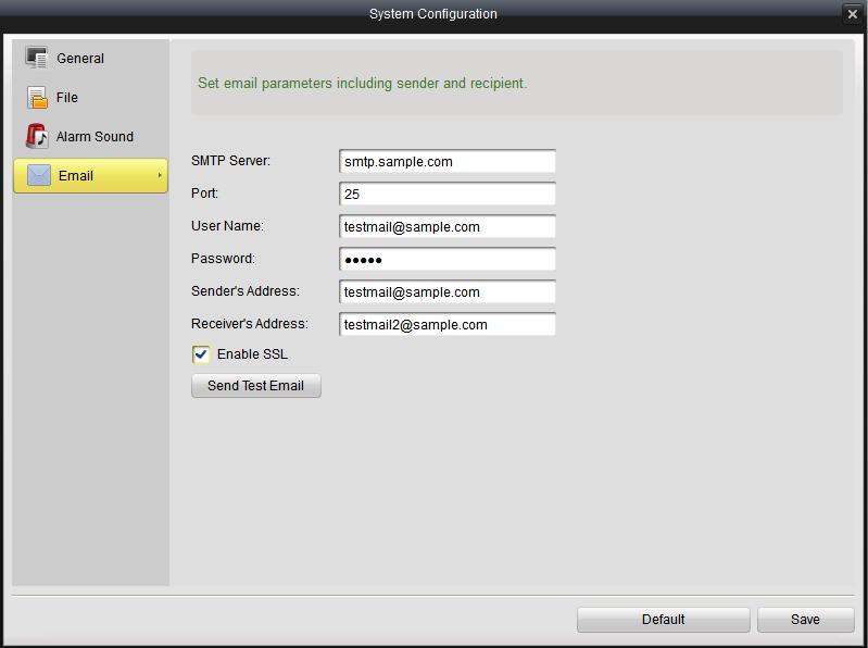
90 Steps: 1. Click each button to open the file browser, and select an audio (.wav) file for the selected alarm type. 2. Click the button to listen to the selected audio file. 3. Click Save button to save the new settings, or click Default to restore default settings Configuration In the configuration interface, you can set the SMTP server, and account information for the alarm actions of the client. Steps: 1. Enter SMTP server, Port, User Name, Password, Sender s Address and Receiver s Address. 2. Click Send Test to check configured successfully. 3. Click Save button to save the new settings, or click Default to restore default settings.
91
VMS-A1 Client Software. User Manual
 VMS-A1 Client Software User Manual Contents Contents... 2 Chapter1. Overview... 4 1.1 Description... 4 1.2 Features & Functions... 4 Chapter2. Update Info... 6 Chapter3. Starting VMS-A1... 7 3.1 Installing
Quick Operation Guide of ivms-4200
 Quick Operation Guide of ivms-4200 V1.02 2012-02-22 Description ivms-4200 is a video management software using a distributed structure to manage all the connectable devices. It can manage the NVR, DVR,
W Box VMS BOX T E C H N O L O G I E S.
 W Box VMS BOX T E C H N O L O G I E S www.wboxtech.eu Contents Contents... 1 Overview... 3 1.1 Description... 3 1.2 Running Environment... 3 1.3 Function Modules... 3 Live view... 6 2.1 User Registration
NVMS1000. User Manual
 NVMS1000 User Manual Contents 1 Software Introduction... 1 1.1 Summary... 1 1.2 Operation Environment... 1 1.3 Install and Uninstall... 2 1.3.1 Install the Software... 2 1.3.2 Uninstall the Software...
NVMS1000. User Manual
 NVMS1000 User Manual Contents 1 Software Introduction... 1 1.1 Summary... 1 1.2 Operation Environment... 1 1.3 Install and Uninstall... 2 1.3.1 Install the Software... 2 1.3.2 Uninstall the Software...
USER MANUAL. Mac Version
 USER MANUAL Mac Version Contents 1 Software Introduction... 1 1.1 Summary... 1 1.2 Install and Uninstall... 1 1.2.1 Install the Software... 1 2 Login Software... 3 2.1 Login... 3 2.2 Control Panel Instruction...
NVMS User Manual
 NVMS-1000 User Manual Contents 1 Software Introduction...1 1.1 Summary... 1 1.2 Operation Environment... 1 1.3 Install and Uninstall... 2 1.3.1 Install the Software... 2 1.3.2 Uninstall the Software...
NVMS User Manual. Version 2.1.0
 NVMS-1000 User Manual Version 2.1.0 Contents 1 Software Introduction... 1 1.1 Summary... 1 1.2 Operation Environment... 1 1.3 Install and Uninstall... 2 1.3.1 Install the Software... 2 1.3.2 Uninstall
ivms-4200 Client Software User Manual alarm shop Hangzhou Hikvision Digital Technology Co., Ltd.
 ivms-4200 Client Software User Manual Hangzhou Hikvision Digital Technology Co., Ltd. Notices The information in this documentation is subject to change without notice and does not represent any commitment
NVMS User Manual
 NVMS-1000 User Manual Contents 1 Software Introduction...1 1.1 Summary... 1 1.2 Operation Environment... 1 1.3 Install and Uninstall... 2 1.3.1 Install the Software... 2 1.3.2 Uninstall the Software...
Quick Start Guide (V1.03) UD.6L0201B1064A01
 UD.6L0201B1064A01") ivms-4200 PCNVR Quick Start Guide (V1.03) UD.6L0201B1064A01 Thank you for purchasing our product. If there is any question or request, please do not hesitate to contact the dealer. This manual applies
ivms-4200 PCNVR Quick Start Guide (V1.03) UD.6L0201B1064A01 Thank you for purchasing our product. If there is any question or request, please do not hesitate to contact the dealer. This manual applies
User s Manual of DVR ULTIMAX. Remote Client Software V wersja 2.40
 User s Manual of DVR ULTIMAX Remote Client Software V 4.0.1 ULTIMAX-304 ULTIMAX-308 ULTIMAX-316 ULTIMAX-504 ULTIMAX-508 ULTIMAX-516 ULTIMAX-704 ULTIMAX-708 ULTIMAX-716 wersja 2.40 Index 1 Software Install,
User Manual of ivms ivms-4200 Client Software. User Manual UD07013B
 ivms-4200 Client Software User Manual 1 UD07013B User Manual COPYRIGHT 2017 Hangzhou Hikvision Digital Technology Co., Ltd. ALL RIGHTS RESERVED. Any and all information, including, among others, wordings,
User Manual of ivms ivms-4200 Client Software. User Manual UD02871B
 ivms-4200 Client Software User Manual UD02871B 1 User Manual COPYRIGHT 2016 Hangzhou Hikvision Digital Technology Co., Ltd. ALL RIGHTS RESERVED. Any and all information, including, among others, wordings,
Manual Version: V1.15. Video Management Software Guard Station User Manual
 Manual Version: V1.15 Video Management Software Guard Station User Manual Thank you for purchasing our product. If there are any questions, or requests, please do not hesitate to contact the dealer. Disclaimer
Client Software-4000(V ) User Manual
 User Manual") Client Software-4000(V2.00.02) User Manual Index Chapter 1 Welcome to Client Software-4000 (V2.0)... 1 1.1 Overview... 1 1.2 Computer Disposition Request... 1 1.3 Convention... 1 Chapter 2 Install & Uninstall...
Client Software-4000(V2.00.02) User Manual Index Chapter 1 Welcome to Client Software-4000 (V2.0)... 1 1.1 Overview... 1 1.2 Computer Disposition Request... 1 1.3 Convention... 1 Chapter 2 Install & Uninstall...
Manual Version: V1.01. ISS Manager Video Management Software User Manual
 Manual Version: V1.01 ISS Manager Video Management Software User Manual Notice The information in this manual is subject to change without notice. Every effort has been made in the preparation of this
ivms-4000(v2.03) User Manual
 User Manual") ivms-4000(v2.03) User Manual Table of Contents ivms-4000(v2.03)...2 User Manual...2 Table of Contents...1 Chapter 1 Welcome to ivms-4000 (V2.03)...4 1.1 Overview...4 1.2 Computer Disposition Request...4
ivms-4000(v2.03) User Manual Table of Contents ivms-4000(v2.03)...2 User Manual...2 Table of Contents...1 Chapter 1 Welcome to ivms-4000 (V2.03)...4 1.1 Overview...4 1.2 Computer Disposition Request...4
errors, or places that do not match the product. If you have any unsolved please contact our technical support department.
 - 0 - Statement: This manual may contain several technical inaccuracies or typographical errors, or places that do not match the product. If you have any unsolved problems in the process of using product
NVMS-5000 NVMS User Manual
 NVMS-5000 NVMS-5000 User Manual NVMS-5000 User Manual Contents 1 Introduction... 4 1.1 NVMS-5000 Brief Introduction... 4 1.1.1 Summerization... 4 1.1.2 Software Architecture... 4 1.2 System Components...
NVMS7000 Client Software
 NVMS7000 Client Software User Manual User Manual About this Manual This Manual is applicable to NVMS7000 Client Software. The Manual includes instructions for using and managing the product. Pictures,
ivms-4200 Client Software User Manual UD.6L0206D1030A01
 ivms-4200 Client Software User Manual UD.6L0206D1030A01 User Manual 2015 Hangzhou Hikvision Digital Technology Co., Ltd. This user manual is intended for users of ivms-4200 Client Software. It includes
Pro71600N3 NVR User Manual
 Pro71600N3 NVR User Manual User Information Admin User Name: Admin Password: IP Address: System Name: Table Of Contents 1. Menu Operation...4 1.1 Main Menu...4 2. Start & Shutdown System...5 2.1 Start
DS-1100KI Network Keyboard User Manual V 2.1.0
 DS-1100KI Network Keyboard User Manual V 2.1.0 (V2.0) Preventive and Cautionary Tips Before connecting and operating your keyboard, please be advised of the following tips: Ensure unit is placed in a well-ventilated,
ivms-4200 Client Software User Manual UD.6L0206D1056A01
 ivms-4200 Client Software User Manual UD.6L0206D1056A01 User Manual COPYRIGHT 2015 Hangzhou Hikvision Digital Technology Co., Ltd. ALL RIGHTS RESERVED. Any and all information, including, among others,
TS View Client Software. User Manual
 TS View Client Software User Manual 2016-03-03 User Manual About this Manual This Manual is applicable to TS View Client Software. The Manual includes instructions for using and managing the product. Pictures,
Pro7804N1 NVR User Manual
 Pro7804N1 NVR User Manual Pro7804N1 User Manual BW R6.indd 1 User Information Admin User Name: Admin Password: IP Address: System Name: Table Of Contents 1. Menu Operation...4 1.1 Main Menu...4 2. Start
Pro7400H1 Hybrid DVR User Manual
 Pro7400H1 Hybrid DVR User Manual User Information Admin User Name: Admin Password: IP Address: System Name: Table Of Contents 1. Menu Operation... 4 1.1 Main Menu... 4 2. Start Up/Shutdown System... 5
Manual Version: V1.01. Video Management Server Client Software User Manual
 Manual Version: V1.01 Video Management Server Client Software User Manual Thank you for purchasing our product. If there are any questions, or requests, please do not hesitate to contact the dealer. Notice
HD IPCameras User's Mannual
 Thank you for purchasing our products, if you have any questions or need, please feel free to contact us. This manual applies to IPC-XXX series of network cameras. This manual may contain technical inaccuracies
Table of Contents: Recorder Web View User Manual. Introduction. 1. Accessing Via Web Browser 2. Installing the plug Live View 1.
 Recorder Web View User Manual Table of Contents: Introduction 1. Accessing Via Web Browser 2. Installing the plug Live View 1. View Page Introduction 2. PTZ Playback 1. Playback Picture 1. Picture Parameters
ivms-4200 Client Software Quick Start Guide UD.6L0202B2174A01
 ivms-4200 Client Software Quick Start Guide UD.6L0202B2174A01 Quick Start Guide COPYRIGHT 2015 Hangzhou Hikvision Digital Technology Co., Ltd. ALL RIGHTS RESERVED. Any and all information, including, among
Video Management Software
 Video Management Software User Manual Web: europesecurity.eu Mail: info@europesecurity.eu Tel.: 0541 352 952 User s Manual 2 Contents CHAPTER : XMS CENTRAL USER MANUAL 1 PC REQUIREMENT 3 2 INSTALL 3 3
VMS2.0 Client Software. User Manual
 VMS2.0 Client Software User Manual Chapter 1 Contents Brief Introduction...1 1.1 Description... 1 1.2 Running Environment...1 Chapter 2 Installation... 2 Chapter 3 Live View... 4 3.1 User Login...4 3.2
Guarding Expert Client Software. User Manual UD02162N
 Guarding Expert Client Software User Manual UD02162N User Manual About this Manual This Manual is applicable to Guarding Expert Client Software. The Manual includes instructions for using and managing
CAMERAS IP START SERIES
 CAMERAS IP START SERIES Contents 1. Login Interface... 3 2. Preview... 4 2.1 Open/Close Preview... 5 2.2 Full-screen Preview... 5 2.3 Electronic Zoom-in... 5 2.3 PTZ Control... 6 3. File Management...
NVMS7000 Client Software User Manual
 NVMS7000 Client Software User Manual i User Manual About this Manual This Manual is applicable to NVMS7000 Client Software. The Manual includes instructions for using and managing the product. Pictures,
Outdoor IPC Web Operation Manual Version1.0
 Outdoor IPC Web Operation Manual Version1.0 1 Table of Contents 1 Network Connection...4 2 Main Interface Introduction...5 2.1 Log in...5 2.2 Monitor Channel Menu Tree...8 2.3 System Menu...10 2.4 Monitor
HIP2P Network Video Camera Client Terminal User Manual
 HIP2P Network Video Camera Client Terminal User Manual Document version:5.1 Page 1 of 34 } Preface Thank you for using our company's products. The network video camera client terminal is used to implement
SunEyes V Series IP Camera P2P CMS user manual
 SunEyes V Series IP Camera P2P CMS user manual Version: 2.0 Date: July. 2015 This document is applicable to all series devices in our company. Page 1 ON page 40 foreword The HiP2P client of IP Camera is
Video Management Software User Manual
 Video Management Software User Manual Manual Version: V1.02 i Thank you for choosing our product. If there are any questions, or requests, please do not hesitate to contact the dealer. Disclaimer CAUTION!
HikCentral Control Client. User Manual
 HikCentral Control Client User Manual Legal Information User Manual 2018 Hangzhou Hikvision Digital Technology Co., Ltd. About this Manual This Manual is subject to domestic and international copyright
Siera CMS Panther v3.0
 1 This manual maybe exist inexact in technology, product feature, operation discrepancy or misprint. The content of the manual will renew according to the product function enhance, and regular change or
Video Surveillance Management Software NVClient V5 User Manual
 Video Surveillance Management Software NVClient V5 User Manual Version: V5.0 Update Date: 2013-12-12 Welcome Thanks for using the Company's digital video surveillance management software. Please read this
JVS-D7216 Standalone DVR User Manual
 Menu JVS-D7216 Standalone DVR User Manual JVS-D7216 Standalone DVR Instructions 1. Introduction..4 1.1 Product Description...4 1.2 Features..4 1.3 Specifications...4 2. Product Features....6 2.1 Panel
NVR Equipment WEB Operation Guide ISSUE V1.1 DATE
 NVR Equipment WEB Operation Guide ISSUE V1.1 DATE 2018-05-15 About This Document About This Document Purpose This document describes how to use the web management system for NVR and the cameras managed
Central Management Software. Cam Viewer 3 Lite. User Manual
 Central Management Software Cam Viewer 3 Lite User Manual Version 1.0.0 Table of Contents 1. System Requirement...4 2. Software Installation...5 3. Configuration Wizard...9 3.1 Channel...10 3.1.1 Adding
Digital Recorder End User Guide. Official UK distribution partner
 Digital Recorder End User Guide Official UK distribution partner 2 Installer Information Contents General Operation Mouse Operation Logging into the System Quick Menu PTZ Control 4 5 5 6 Playback Operation
Network Video Monitor Software
 Network Video Monitor Software V2.0.0.7 Operation menu 1 www.opax.com Chapter 1 Product Overview 1.1 Performance instruction Network video monitoring software is a centralized management software for I8
K6 Series IP Camera Web Operation Manual
 K6 Series IP Camera Web Operation Manual Version1.3 1 Table of Contents 1 Network Connection...4 2 Main Interface Introduction...5 2.1 Log in...5 2.2 Monitor Channel Menu Tree...7 2.3 System Menu...10
Central Management Software for NVR-915 / NVR-1615 CV5-M256
 Central Management Software for NVR-915 / NVR-1615 Table of Contents Chapter 1. Main Console... 4 1.1 Tool Bar... 4 1.2 NVR List... 5 1.3 Division List... 7 1.4 Group List... 9 1.5 PTZ Panel...11 1.6 Operation
IP Solution Intelligent Surveillance Solution
 IP Solution Intelligent Surveillance Solution user s manual Table of Contents TABLE OF CONTENTS TABLE OF CONTENTS...1 SYSTEM REQUIREMENT...5 INSTALLATION...6 QUICK START...10 1. MAIN CONSOLE...14 1.1 Start...16
User Manual. Central Monitoring Software for TER-series recorders. CenPro
 EN User Manual Central Monitoring Software for TER-series recorders CenPro Contents CENPRO USER MANUAL 1 PC REQUIREMENT 3 2 INSTALL 3 3 UNINSTALL 5 4 BASIC OPERATION 7 4.1 Log In 7 4.2 Screen Layout 8
Digital Recorder End User Guide
 Digital Recorder End User Guide metcalfeallen www.metcalfeallen.co.uk - 01884 38222 - admin@metcalfeallen.co.uk Installer Information Metcalfe Allen Ltd Unit 7 Saunders Way Kingsmill Industrial Estate
Quick Start Guide 4/8/16-CH DVR.
 Quick Start Guide 4/8/16-CH DVR 1. Install Hard Drive &DVD Writer 1.1 Install Hard Drive Notice: 1. Support two SATA hard drives. Please use the hard drive the manufacturers recommend specially for security
IMS200 SURVEILLANCE SYSTEM USER MANUAL
 IMS200 SURVEILLANCE SYSTEM USER MANUAL 1 PRECAUTIONS The contents of this manual may change due to product upgrades or other reasons. We have the right to make changes of the contents without notice. This
LS VISION TECHNOLOGY CO.,LTD. Network Surveillance System Client Operating Instructions
 Network Surveillance System Client Operating Instructions 1 Directory 1. Overview... 4 2. Runtime Environment... 4 2.1 Machine Configuration Requirements...4 2.2 Operating System Requirements... 4 3. Software
HikCentral Control Client User Manual
 User Manual Table of Content Disclaimer... 1 Overview... 2 Description... 2 Function Modules... 3 Installing and Uninstalling the Client... 5 Accessing via Control Client... 6 Login via Control Client...
USER S MANUAL Version 2.3.3
 USER S MANUAL Version 2.3.3 1 CONTENTS C H A P T E R 1 Introduction... 7 Overview... 8 Product Features... 8 Rear Panel... 10 Product Application Diagram... 11 Operating Your NVR... 12 Front Panel... 12
User Manual of Client Software for Embedded DVRDVS (Version 1.4)
") User Manual of Client Software for Embedded DVRDVS (Version 1.4) 1 Index Version Description...3 Chapter 1 Client Software Installation...6 1.1 Notice...6 1.2 Installation...7 Chapter 2 Client Software
User Manual of Client Software for Embedded DVRDVS (Version 1.4) 1 Index Version Description...3 Chapter 1 Client Software Installation...6 1.1 Notice...6 1.2 Installation...7 Chapter 2 Client Software
SURVEILLANCE KIT USER MANUAL. All in One Series
 SURVEILLANCE KIT USER MANUAL All in One Series Contents Part one Basic Operation 1 1. Basic Installation 1 1. Hard Disk Installation 1 2. Mouse Connection 1 2. Starting 1 3. Turn Off 1 4. Login 2 5. Preview
User s Manual. Surveillance Client PC Software for Windows OS & Mac OS Central Management Software. Surveillance Client
 User s Manual Surveillance Client PC Software for Windows OS & Mac OS Central Management Software Surveillance Client Contents 1 Product Description...4 1.1 Important Disclaimer...4 1.2 Software Related
4CH/ 8CH/ 16CH Digital Video Recorder
 4CH/ 8CH/ 16CH Digital Video Recorder DVR204B/ 208B/ 216B INSTRUCTION MANUAL DIRECTORY CHAPTER 1 Hard Disk Installing (Standard shipping products include neither HDD or R/W)...2 CHAPTER 2 Panel Appearance...4
TruVision Recorder Operator Guide
 TruVision Recorder Operator Guide Live view In the viewer you can see displayed on the live image the current date and time, camera name, and whether a recording is in progress. Information on the system
32 CHANNEL SURVEILLANCE SYSTEM MANUAL
 32 CHANNEL SURVEILLANCE SYSTEM MANUAL English version 1.0 SOFTWARE GUIDE Software Guide for Digimerge Networkable Cameras Copyright 2007 Digimerge Technologies Inc. 32-CH Surveillance System Note This
HikCentral Quick Start Guide
 HikCentral Quick Start Guide Quick Start Guide COPYRIGHT 2018 Hangzhou Hikvision Digital Technology Co., Ltd. ALL RIGHTS RESERVED. Any and all information, including, among others, wordings, pictures,
DS-9000 Series Hybrid Net DVR
 DS-9000 Series Hybrid Net DVR Overview DS-9000 series net DVR is the Hybrid DVR of a new generation designed by HIKVISION. The product combines various patents, along with advanced IT technologies such
DDNS UPNP
 PL-ADR0608/16-H2 PL-ADR0604-H2 Content 1 Product Introduction... 3 2 Installation... 3 2.1 Open-package Inspection... 3 2.2 Hard Disk Installation... 3 3. Local operation guide... 3 3.1 Boot operation...
Quick Start Guide. Menu Structure. Startup and Shutdown. Using the Setup Wizard. DS-8100-S Series DVR (V2.0.1)
") Quick Start Guide DS-8100-S Series DVR (V2.0.1) Menu Structure The menu structure of the DS-8100-S Series DVR is as followed: 1. Enter the Shutdown menu by clicking on Menu > Shut down. 2. Select the Shutdown
Quick Start Guide DS-8100-S Series DVR (V2.0.1) Menu Structure The menu structure of the DS-8100-S Series DVR is as followed: 1. Enter the Shutdown menu by clicking on Menu > Shut down. 2. Select the Shutdown
Network Keyboard. User Manual UD.6L0203D1056A01
 Network Keyboard User Manual UD.6L0203D1056A01 Preventive and Cautionary Tips Before connecting and operating your keyboard, please be advised of the following tips: Ensure unit is placed in a well-ventilated,
Error! Bookmark not defined.
 HD-NVR user manual Directory Part one Basic Operation... 3 1. Basic Installation... 3 1.1 Hard Disk Installation... 3 1.2 Mouse Connection... 3 2. Starting... 3 3.Turn Off... 3 4.Login... 4 5.Preview...
Quick Start Guide 4/8/16-Ch DVR
 Quick Start Guide 4/8/16-Ch DVR 1 1. Install Hard Drive &DVD Writer 1.1Install Hard Drive Notice: 1. Support two SATA hard drives. Please use the hard drive the manufacturers recommend specially for security
Video recorders DX Series
 Page: 1 AHD DVR cameras, analog, IP CMS Program Manual How to install and use the client program to the DVR Page: 2 Contents of this handbook This manual describes how to install and use the CMS program
IP WEB User Manual V2.0
 IP WEB User Manual V2.0 Please read carefully before installing or contacting your supplier. The information contained at the time of printing is correct, but is subject to change without notice. This
STORM Video Management Software User s Manual
 STORM Video Management Software User s Manual Version 2.0.1 Table of Contents 1. OVERVIEW AND ENVIRONMENT... 1 1.1 Overview... 1 1.2 STORM Interface... 1 2. LOGIN... 5 2.1 Initialize Device... 5 2.2 Login
HikCentral FAQ. Blazer Pro V2.1 Frequently Asked Questions (FAQ)
") HikCentral FAQ Blazer Pro V2.1 Frequently Asked s (FAQ) HikCentral FAQ Frequently Asked s COPYRIGHT 2017 Hangzhou Hikvision Digital Technology Co., Ltd. ALL RIGHTS RESERVED. Any and all information, including,
HikCentral FAQ Blazer Pro V2.1 Frequently Asked s (FAQ) HikCentral FAQ Frequently Asked s COPYRIGHT 2017 Hangzhou Hikvision Digital Technology Co., Ltd. ALL RIGHTS RESERVED. Any and all information, including,
Quick Start Guide 4/8/16/24-Ch DVR
 Quick Start Guide 4/8/16/24-Ch DVR 1.1 Install Hard Drive 4/8/16/24-CH DVR Quick Start Guide Notice: 1.4/3/16-ch DVR supports one SATA hard drive. 24-ch DVR supports three SATA hard drives. Please use
A-45 Quick Setup Guide
 www.advidia.com A-45 Quick Setup Guide Table of Contents A. Physical Camera Description... 3 B. Installation... 5 C. Search and Modify IP... 8 D. Preview via Web Browser...11 E. Web Interface Configuration...14
VIP Kit 16 channel software manual. Set up and user manual for Vista s VIP Kit software IP CCTV system
 VIP Kit 16 channel software manual Set up and user manual for Vista s VIP Kit software IP CCTV system Table of Contents 1. Introduction of Program... 1 2. Preparations before operating... 1 2.1 Minimum
B3223P23 Release Notes. Zhejiang Uniview Technologies Co., Ltd.
 Zhejiang Uniview Technologies Co., Ltd. Keywords: Version information, usage notes, precautions. Abstract: This document provides information about the B3223P23 board software, including version Acronym
DS-9600NI-ST Series NVR. Technical Specification
 DS-9600NI-ST Series NVR Technical Specification Notices The information in this documentation is subject to change without notice and does not represent any commitment on behalf of HIKVISION. HIKVISION
Product and company names appearing in this document are trademarks of each respective company or organization.
 . CMS_beta LEGAL INFORMATION Reproduction, transfer, distribution or storage of part or all of the contents in this document in any form without the prior written permission of the company is prohibited.
Enterprise Pro Surveillance System User s Manual
 Enterprise Pro Surveillance System User s Manual 1 Table of Contents 1 FEATURES... 6 2 INSTALLATION... 8 2.1 Environment...8 2.2 Installation...8 2.3 Un-installation...10 3 NAVIGATION AND CONTROLS OF THE
10 Network Configuration 45 Basic Configuration 45 PPPoE 46 DDNS 46 UPnP
 Contents Preface 1 Part I Local Operations 1 1 Before You Begin 1 Login 1 Local Operations 2 2 Initial Configuration 3 Preparation 3 Startup Wizard 3 3 Preview 7 Status Icons in the Preview Window 7 Preview
PROVISION-ISR. User Manual. All S Series IP Cameras I1-390IPS36 DI-390IPS36 I1-330IPS36 DI-330IPS36. All rights reserved Provision-ISR
 (v4.0.2) PROVISION-ISR All S Series IP Cameras I1-390IPS36 DI-390IPS36 I1-330IPS36 DI-330IPS36 User Manual All rights reserved Provision-ISR Notes on Safety Please refer to the technical specs to choose
BlackHawk for MAC Software User Guide
 BlackHawk for MAC Software User Guide Products: BLK-DH2 Series and BLK-HD Series DVRs Please read this manual before using your software, and always follow the instructions for safety and proper use. Save
Network Video Recorder
 Network Video Recorder User Manual Regulatory information FCC information FCC compliance: This equipment has been tested and found to comply with the limits for a digital device, pursuant to part 15 of
R4, R8, R16 Digital Video Recorders Quick Setup Guide
 R4, R8, R16 Digital Video Recorders Quick Setup Guide This guide provides instructions to initially setup the R16 (16 channel) digital video recorders (DVR). The DVR supports these advanced features: 2
User Manual of ivms ivms-4200 Client Software. User Manual UD06350B
 ivms-4200 Client Software User Manual 1 UD06350B User Manual COPYRIGHT 2017 Hangzhou Hikvision Digital Technology Co., Ltd. ALL RIGHTS RESERVED. Any and all information, including, among others, wordings,
Network Video Recorder User Manual
 Network Video Recorder User Manual UD.6L0202D1132A02 Regulatory information FCC information FCC compliance: This equipment has been tested and found to comply with the limits for a digital device, pursuant
HikCentral Control Client. User Manual
 HikCentral Control Client User Manual Legal Information User Manual 2018 Hangzhou Hikvision Digital Technology Co., Ltd. About this Manual This Manual is subject to domestic and international copyright
ivms-4000 (V ) Decoder Control User Manual
 Decoder Control User Manual") ivms-4000 (V2.03.07) Decoder Control User Manual Table of Contents Decoder Control... 1 User Manual... 1 Table of Contents... 1 Chapter 1 Introduction... 2 1.1 Overview... 2 1.2 Computer Disposition Request...
ivms-4000 (V2.03.07) Decoder Control User Manual Table of Contents Decoder Control... 1 User Manual... 1 Table of Contents... 1 Chapter 1 Introduction... 2 1.1 Overview... 2 1.2 Computer Disposition Request...
Grandstream Networks, Inc. GSurf User Manual
 Grandstream Networks, Inc. GSurf User Manual GSurf Contents Contents Introduction 3 Installation 4 Minimum Recommended Requirements 4 Login 4 Main Window 5 Menu Items 5 Toolbar Items 6 Play Bar Items 7
NVR Client system. User Guide
 NVR Client system User Guide Content Chapter1 Start up and Main interface 2 1.1 Start up 2 1.2 Main interface 6 1.2.1 Interface description 6 1.2.2 Select playback channel 8 1.3 System Menu 11 1.3.1 Remote
Dual Output SDI+IP PTZ Camera
 1 Dual Output SDI+IP PTZ Camera USER MANUAL Part Two: Network Camera User Manual Version: SN-IP-07082017 2017 Bolin Technology 2 Contents PART TWO: NETWORK CAMERA USER MANUAL... 3 NETWORK CONNECTION...
ivms-4200 Access Control Client User Manual UD00895N
 ivms-4200 Access Control Client User Manual UD00895N User Manual About this Manual This Manual is applicable to ivms-4200 Access Control Client. The Manual includes instructions for using and managing
Video Capture Card Manual
 Video Capture Card Manual 1. System Login System installation is completed, will generate desktop < DVR Surveillance System> icon, please double-click operation. Or choose Start -> All Programs -> DVR
Lorex Client 7.0 & Lorex Message Master
 Lorex Client 7.0 & Lorex Message Master Software Manual English Version 1.0 MODELS: L19WD Series www.lorexcctv.com Includes L19WD800 & L19WD1600 Copyright 2008 Lorex Technology Inc. Table of Contents Table
ivms-4200 Client Software ivms-4200 Main Features Live View Recording Alarm Management
 ivms-4200 Client Software ivms-4200 is versatile video management software for the DVRs, NVRs, IP cameras, encoders, access control devices, security control panels, video intercom devices, decoders, VCA
Unisight DVR System. Unisight DVR Manual. Ver rev1.3.4
 Unisight DVR Manual Ver2.7.1027 rev1.3.4 1 Table of Contents System Requirements.8 Unisight DVR Server.. 8 Server Hardware Requirements...8 Server Software Requirements 8 Client Hardware Requirements...