FUJITSU Software ServerView Resource Orchestrator Cloud Edition V Operation Guide. Windows/Linux
|
|
|
- Simon Tyler
- 5 years ago
- Views:
Transcription


1 FUJITSU Software ServerView Resource Orchestrator Cloud Edition V3.1.2 Operation Guide Windows/Linux J2X ENZ0(03) June 2014
2 Preface Purpose of This Document This manual explains how to operate FUJITSU Software ServerView Resource Orchestrator Cloud Edition (hereinafter Resource Orchestrator). Intended Readers This manual is written for system administrators who will use Resource Orchestrator to operate the infrastructure in private cloud or data center environments. When setting up systems, it is assumed that readers have the basic knowledge required to configure the servers, storage, network devices, and server virtualization software to be installed. Additionally, a basic understanding of directory services such as Active Directory and LDAP is necessary. Structure of This Document This manual is composed as follows: Section 1 Overview Chapter 1 Overview of Operations, Maintenance, and Monitoring Provides an overview of the operation, maintenance, and monitoring of Resource Orchestrator. Section 2 Operation Chapter 2 Starting and Stopping Managers and Agents Explains the methods for deliberately starting and stopping managers and agents. Chapter 3 Managing User Accounts Explains the management of user accounts. Chapter 4 Managing Tenants Explains the management of tenants. Chapter 5 Managing Templates Explains the management of templates. Chapter 6 Managing Resources and Resource Pools Explains the management of resources and resource pools. Chapter 7 Management of L-Platform Explains the management of L-Platforms. Chapter 8 Changing Settings Explains how to modify various setting information. Section 3 Maintenance Chapter 9 Hardware Maintenance Explains the maintenance of hardware. Chapter 10 Backup and Restoration Explains how to use the backup and restore provided by Resource Orchestrator. - i -
3 Section 4 Monitoring Chapter 11 Monitoring Resources Explains how to monitor the configuration and status of managed resources. Chapter 12 Collecting Power Consumption Data and Displaying Graphs Explains how to export the power consumption data collected from registered power monitoring targets and how to display it as graphs, and also describes the exported data's format. Chapter 13 Monitoring Resource Pools (Dashboard) Explains the monitoring of resource pools. Chapter 14 Monitoring L-Platforms Explains the monitoring of L-Platforms. Chapter 15 Accounting Explains charging. Chapter 16 Monitoring Logs Explains the monitoring of logs. Chapter 17 Event Handling Explains the event handling function. Section 5 High Availability and Disaster Recovery Chapter 18 High Availability of Managed Resources Explains failover. Chapter 19 Disaster Recovery Explains the Disaster Recovery function for L-Servers. Appendix A Notes on Operating ServerView Resource Orchestrator Gives important reminders for the operation of Resource Orchestrator. Appendix B Metering Log Explains metering logs. Document Conventions The notation in this manual conforms to the following conventions. - When there is different information for the different versions of Resource Orchestrator, it is indicated as follows: [All Editions] [Cloud Edition] [Virtual Edition] Sections relevant for all editions Sections related to Cloud Edition Sections related to Virtual Edition - When using Resource Orchestrator and the functions necessary differ due to the necessary basic software (OS), it is indicated as follows: [Windows Manager] [Linux Manager] [Windows] Sections related to Windows manager Sections related to Linux manager Sections related to Windows - ii -
4 [Linux] [Solaris] [VMware] [Hyper-V] [Xen] [KVM] [Solaris Zones] Sections related to Linux Sections related to Solaris Sections related to VMware Sections related to Hyper-V Sections related to RHEL5-Xen Sections related to RHEL-KVM Sections related to Solaris zones [OVM for x86 2.2] Sections related to Oracle VM Server for x [OVM for x86 3.2] Sections related to Oracle VM Server for x [OVM for SPARC] [Citrix Xen] [Physical Servers] Sections related to Oracle VM Server for SPARC Sections related to Citrix XenServer Sections related to physical servers - Unless specified otherwise, the blade servers mentioned in this manual refer to PRIMERGY BX servers. - Oracle Solaris may also be indicated as Solaris, Solaris Operating System, or Solaris OS. - Oracle Solaris Zones may also be indicated as Solaris Containers or Solaris Container. - Oracle VM Server for x86 may also be indicated as Oracle VM. - In Resource Orchestrator, the following servers are referred to as SPARC Enterprise. - SPARC Enterprise M3000/M4000/M5000/M8000/M SPARC Enterprise T5120/T5140/T5220/T5240/T In Resource Orchestrator, the following servers are referred to as SPARC M10. - SPARC M10-1/M10-4/M10-4S - Fujitsu M10 is the product name used for SPARC M10 when they are sold outside Japan. - References and character strings or values requiring emphasis are indicated using double quotes ( " ). - Window names, dialog names, menu names, and tab names are shown enclosed by brackets ( [ ] ). - Button names are shown enclosed by angle brackets (< >) or square brackets ([ ]). - The order of selecting menus is indicated using [ ]-[ ]. - Text to be entered by the user is indicated using bold text. - Variables are indicated using italic text and underscores. - The ellipses ("...") in menu names, indicating settings and operation window startup, are not shown. - The ">" used in Windows is included in usage examples. When using Linux, read ">" as meaning "#". - If using Windows 8 or Windows Server 2012, please note the following: Operations descriptions in this manual use examples assuming operating systems up to Windows 7 and Windows Server if using this product with Windows 8 or Windows Server 2012, read instructions regarding the [Start] menu as if they were instructions for the [Apps] page. Display the [Apps] page by right-clicking in the [Start] screen, and then clicking on [All apps]. - When using Resource Orchestrator on Windows 8.1 and Windows Server 2012 R2, please note the following. When OS operations are explained in this manual, the examples assume OSs up to Windows 7 and Windows Server When using Resource Orchestrator on Windows 8.1 or Windows Server 2012 R2, take explanations regarding the [Start] menu as indicating the [Apps] screen. The [Apps] screen can be displayed by swiping the [Start] screen from bottom to top, or clicking the downward facing arrow on the lower-left of the [Start] screen. - iii -
5 Menus in the ROR console Operations on the ROR console can be performed using either the menu bar or pop-up menus. By convention, procedures described in this manual only refer to pop-up menus. Regarding Installation Folder Paths The installation folder path may be given as C:\Fujitsu\ROR in this manual. Replace it as shown below. - When using Windows 64-bit (x64) C:\Program Files (x86)\resource Orchestrator - When using Windows 32-bit (x86) C:\Program Files\Resource Orchestrator Command Examples The paths used in command examples may be abbreviated. When using commands, execute them using the paths in the "Name" column in the "Reference Guide (Command) VE" and the "Reference Guide (Command/XML) CE". Web Site URLs URLs provided as reference sources within the main text are correct as of June Please understand that they are subject to change without notice. Abbreviations The following abbreviations are used in this manual: Windows Abbreviation Products Microsoft(R) Windows Server(R) 2003 R2, Standard Edition Microsoft(R) Windows Server(R) 2003 R2, Enterprise Edition Microsoft(R) Windows Server(R) 2003 R2, Standard x64 Edition Microsoft(R) Windows Server(R) 2003 R2, Enterprise x64 Edition Microsoft(R) Windows Server(R) 2008 Standard Microsoft(R) Windows Server(R) 2008 Enterprise Microsoft(R) Windows Server(R) 2008 R2 Standard Microsoft(R) Windows Server(R) 2008 R2 Enterprise Microsoft(R) Windows Server(R) 2008 R2 Datacenter Microsoft(R) Windows Server(R) 2012 Standard Microsoft(R) Windows Server(R) 2012 Datacenter Microsoft(R) Windows Server(R) 2012 R2 Standard Microsoft(R) Windows Server(R) 2012 R2 Datacenter Microsoft(R) Windows(R) XP Professional operating system Windows Vista(R) Business Windows Vista(R) Enterprise Windows Vista(R) Ultimate Windows(R) 7 Professional Windows(R) 7 Ultimate Windows(R) 8 Pro Windows(R) 8 Enterprise - iv -
6 Abbreviation Windows Server 2003 Windows 2003 x64 Edition Windows Server 2008 Windows 2008 x86 Edition Windows 2008 x64 Edition Windows Server 2012 Windows PE Windows XP Windows Vista Windows 7 Windows 8 Linux Windows(R) 8.1 Pro Windows(R) 8.1 Enterprise Products Microsoft(R) Windows Server(R) 2003 R2, Standard Edition Microsoft(R) Windows Server(R) 2003 R2, Enterprise Edition Microsoft(R) Windows Server(R) 2003 R2, Standard x64 Edition Microsoft(R) Windows Server(R) 2003 R2, Enterprise x64 Edition Microsoft(R) Windows Server(R) 2003 R2, Standard x64 Edition Microsoft(R) Windows Server(R) 2003 R2, Enterprise x64 Edition Microsoft(R) Windows Server(R) 2008 Standard Microsoft(R) Windows Server(R) 2008 Enterprise Microsoft(R) Windows Server(R) 2008 R2 Standard Microsoft(R) Windows Server(R) 2008 R2 Enterprise Microsoft(R) Windows Server(R) 2008 R2 Datacenter Microsoft(R) Windows Server(R) 2008 Standard (x86) Microsoft(R) Windows Server(R) 2008 Enterprise (x86) Microsoft(R) Windows Server(R) 2008 Standard (x64) Microsoft(R) Windows Server(R) 2008 Enterprise (x64) Microsoft(R) Windows Server(R) 2012 Standard Microsoft(R) Windows Server(R) 2012 Datacenter Microsoft(R) Windows Server(R) 2012 R2 Standard Microsoft(R) Windows Server(R) 2012 R2 Datacenter Microsoft(R) Windows(R) Preinstallation Environment Microsoft(R) Windows(R) XP Professional operating system Windows Vista(R) Business Windows Vista(R) Enterprise Windows Vista(R) Ultimate Windows(R) 7 Professional Windows(R) 7 Ultimate Windows(R) 8 Pro Windows(R) 8 Enterprise Windows(R) 8.1 Pro Windows(R) 8.1 Enterprise Red Hat(R) Enterprise Linux(R) 5 (for x86) Red Hat(R) Enterprise Linux(R) 5 (for Intel64) Red Hat(R) Enterprise Linux(R) 5.1 (for x86) Red Hat(R) Enterprise Linux(R) 5.1 (for Intel64) Red Hat(R) Enterprise Linux(R) 5.2 (for x86) Red Hat(R) Enterprise Linux(R) 5.2 (for Intel64) Red Hat(R) Enterprise Linux(R) 5.3 (for x86) Red Hat(R) Enterprise Linux(R) 5.3 (for Intel64) Red Hat(R) Enterprise Linux(R) 5.4 (for x86) Red Hat(R) Enterprise Linux(R) 5.4 (for Intel64) Red Hat(R) Enterprise Linux(R) 5.5 (for x86) Red Hat(R) Enterprise Linux(R) 5.5 (for Intel64) Red Hat(R) Enterprise Linux(R) 5.6 (for x86) Red Hat(R) Enterprise Linux(R) 5.6 (for Intel64) Red Hat(R) Enterprise Linux(R) 5.7 (for x86) Red Hat(R) Enterprise Linux(R) 5.7 (for Intel64) Red Hat(R) Enterprise Linux(R) 5.8 (for x86) Red Hat(R) Enterprise Linux(R) 5.8 (for Intel64) Red Hat(R) Enterprise Linux(R) 5.9 (for x86) - v -
7 Abbreviation Red Hat Enterprise Linux Red Hat Enterprise Linux 5 Products Red Hat(R) Enterprise Linux(R) 5.9 (for Intel64) Red Hat(R) Enterprise Linux(R) 5.10 (for x86) Red Hat(R) Enterprise Linux(R) 5.10 (for Intel64) Red Hat(R) Enterprise Linux(R) 6.2 (for x86) Red Hat(R) Enterprise Linux(R) 6.2 (for Intel64) Red Hat(R) Enterprise Linux(R) 6.3 (for x86) Red Hat(R) Enterprise Linux(R) 6.3 (for Intel64) Red Hat(R) Enterprise Linux(R) 6.4 (for x86) Red Hat(R) Enterprise Linux(R) 6.4 (for Intel64) Red Hat(R) Enterprise Linux(R) 6.5 (for x86) Red Hat(R) Enterprise Linux(R) 6.5 (for Intel64) SUSE(R) Linux Enterprise Server 11 for x86 SUSE(R) Linux Enterprise Server 11 for EM64T Red Hat(R) Enterprise Linux(R) 5 (for x86) Red Hat(R) Enterprise Linux(R) 5 (for Intel64) Red Hat(R) Enterprise Linux(R) 5.1 (for x86) Red Hat(R) Enterprise Linux(R) 5.1 (for Intel64) Red Hat(R) Enterprise Linux(R) 5.2 (for x86) Red Hat(R) Enterprise Linux(R) 5.2 (for Intel64) Red Hat(R) Enterprise Linux(R) 5.3 (for x86) Red Hat(R) Enterprise Linux(R) 5.3 (for Intel64) Red Hat(R) Enterprise Linux(R) 5.4 (for x86) Red Hat(R) Enterprise Linux(R) 5.4 (for Intel64) Red Hat(R) Enterprise Linux(R) 5.5 (for x86) Red Hat(R) Enterprise Linux(R) 5.5 (for Intel64) Red Hat(R) Enterprise Linux(R) 5.6 (for x86) Red Hat(R) Enterprise Linux(R) 5.6 (for Intel64) Red Hat(R) Enterprise Linux(R) 5.7 (for x86) Red Hat(R) Enterprise Linux(R) 5.7 (for Intel64) Red Hat(R) Enterprise Linux(R) 5.8 (for x86) Red Hat(R) Enterprise Linux(R) 5.8 (for Intel64) Red Hat(R) Enterprise Linux(R) 5.9 (for x86) Red Hat(R) Enterprise Linux(R) 5.9 (for Intel64) Red Hat(R) Enterprise Linux(R) 5.10 (for x86) Red Hat(R) Enterprise Linux(R) 5.10 (for Intel64) Red Hat(R) Enterprise Linux(R) 6.2 (for x86) Red Hat(R) Enterprise Linux(R) 6.2 (for Intel64) Red Hat(R) Enterprise Linux(R) 6.3 (for x86) Red Hat(R) Enterprise Linux(R) 6.3 (for Intel64) Red Hat(R) Enterprise Linux(R) 6.4 (for x86) Red Hat(R) Enterprise Linux(R) 6.4 (for Intel64) Red Hat(R) Enterprise Linux(R) 6.5 (for x86) Red Hat(R) Enterprise Linux(R) 6.5 (for Intel64) Red Hat(R) Enterprise Linux(R) 5 (for x86) Red Hat(R) Enterprise Linux(R) 5 (for Intel64) Red Hat(R) Enterprise Linux(R) 5.1 (for x86) Red Hat(R) Enterprise Linux(R) 5.1 (for Intel64) Red Hat(R) Enterprise Linux(R) 5.2 (for x86) Red Hat(R) Enterprise Linux(R) 5.2 (for Intel64) Red Hat(R) Enterprise Linux(R) 5.3 (for x86) Red Hat(R) Enterprise Linux(R) 5.3 (for Intel64) Red Hat(R) Enterprise Linux(R) 5.4 (for x86) Red Hat(R) Enterprise Linux(R) 5.4 (for Intel64) Red Hat(R) Enterprise Linux(R) 5.5 (for x86) Red Hat(R) Enterprise Linux(R) 5.5 (for Intel64) Red Hat(R) Enterprise Linux(R) 5.6 (for x86) - vi -
8 Abbreviation Red Hat Enterprise Linux 6 RHEL5-Xen RHEL-KVM DOS SUSE Linux Enterprise Server Products Red Hat(R) Enterprise Linux(R) 5.6 (for Intel64) Red Hat(R) Enterprise Linux(R) 5.7 (for x86) Red Hat(R) Enterprise Linux(R) 5.7 (for Intel64) Red Hat(R) Enterprise Linux(R) 5.8 (for x86) Red Hat(R) Enterprise Linux(R) 5.8 (for Intel64) Red Hat(R) Enterprise Linux(R) 5.9 (for x86) Red Hat(R) Enterprise Linux(R) 5.9 (for Intel64) Red Hat(R) Enterprise Linux(R) 5.10 (for x86) Red Hat(R) Enterprise Linux(R) 5.10 (for Intel64) Red Hat(R) Enterprise Linux(R) 6.2 (for x86) Red Hat(R) Enterprise Linux(R) 6.2 (for Intel64) Red Hat(R) Enterprise Linux(R) 6.3 (for x86) Red Hat(R) Enterprise Linux(R) 6.3 (for Intel64) Red Hat(R) Enterprise Linux(R) 6.4 (for x86) Red Hat(R) Enterprise Linux(R) 6.4 (for Intel64) Red Hat(R) Enterprise Linux(R) 6.5 (for x86) Red Hat(R) Enterprise Linux(R) 6.5 (for Intel64) Red Hat(R) Enterprise Linux(R) 5.4 (for x86) Linux Virtual Machine Function Red Hat(R) Enterprise Linux(R) 5.4 (for Intel64) Linux Virtual Machine Function Red Hat(R) Enterprise Linux(R) 6.2 (for x86) Virtual Machine Function Red Hat(R) Enterprise Linux(R) 6.2 (for Intel64) Virtual Machine Function Red Hat(R) Enterprise Linux(R) 6.3 (for x86) Virtual Machine Function Red Hat(R) Enterprise Linux(R) 6.3 (for Intel64) Virtual Machine Function Red Hat(R) Enterprise Linux(R) 6.4 (for x86) Virtual Machine Function Red Hat(R) Enterprise Linux(R) 6.4 (for Intel64) Virtual Machine Function Red Hat(R) Enterprise Linux(R) 6.5 (for x86) Virtual Machine Function Red Hat(R) Enterprise Linux(R) 6.5 (for Intel64) Virtual Machine Function Microsoft(R) MS-DOS(R) operating system, DR DOS(R) SUSE(R) Linux Enterprise Server 11 for x86 SUSE(R) Linux Enterprise Server 11 for EM64T OVM for x Oracle(R) VM Server for x OVM for x OVM for SPARC Oracle VM Manager Citrix XenServer ESC GLS Navisphere Solutions Enabler MSFC Oracle VM Server for x86 v3.2.1 Oracle VM Server for x86 v3.2.2 Oracle VM Server for x86 v3.2.3 Oracle VM Server for x86 v3.2.4 Oracle VM Server for x86 v3.2.6 Oracle VM Server for x86 v3.2.7 Oracle(R) VM Server for SPARC Oracle(R) VM Manager Citrix XenServer(R) 6.0 Citrix XenServer(R) Citrix XenServer(R) ETERNUS SF Storage Cruiser PRIMECLUSTER GLS EMC Navisphere Manager EMC Solutions Enabler Microsoft Failover Cluster - vii -
9 Solaris SCVMM VMware VMware ESX Abbreviation Products Oracle Solaris10 05/09 (Update7) Media Pack Oracle Solaris11 11/11 Media Pack Oracle Solaris11.1 Media Pack System Center Virtual Machine Manager 2008 R2 System Center 2012 Virtual Machine Manager System Center 2012 R2 Virtual Machine Manager VMware vsphere(r) 4 VMware vsphere(r) 4.1 VMware vsphere(r) 5 VMware vsphere(r) 5.1 Vmware vsphere(r) 5.5 VMware(R) ESX(R) VMware ESX 4 VMware(R) ESX(R) 4 VMware ESXi VMware(R) ESXi(TM) VMware ESXi 5.0 VMware(R) ESXi(TM) 5.0 VMware ESXi 5.1 VMware(R) ESXi(TM) 5.1 VMware ESXi 5.5 VMware(R) ESXi(TM) 5.5 VMware Tools VMware(R) Tools VMware vsphere 4.0 VMware vsphere(r) 4.0 VMware vsphere 4.1 VMware vsphere(r) 4.1 VMware vsphere 5 VMware vsphere(r) 5 VMware vsphere 5.1 VMware vsphere(r) 5.1 VMware vsphere 5.5 VMware vsphere(r) 5.5 VMware vsphere Client VMware vcenter Server VMware vclient VMware FT VMware DRS VMware DPM VMware vds VMware Storage VMotion VIOM BladeLogic Internet Explorer ServerView Agent RCVE ROR ROR VE VMware vsphere(r) Client VMware(R) vcenter(tm) Server VMware(R) vclient(tm) VMware(R) Fault Tolerance VMware(R) Distributed Resource Scheduler VMware(R) Distributed Power Management VMware(R) vnetwork Distributed Switch VMware(R) Storage VMotion ServerView Virtual-IO Manager BMC BladeLogic Server Automation Windows(R) Internet Explorer(R) 8 Windows(R) Internet Explorer(R) 9 Windows(R) Internet Explorer(R) 10 Windows(R) Internet Explorer(R) 11 ServerView SNMP Agents for MS Windows (32bit-64bit) ServerView Agents Linux ServerView Agents VMware for VMware ESX Server ServerView Resource Coordinator VE FUJITSU Software ServerView Resource Orchestrator FUJITSU Software ServerView Resource Orchestrator Virtual Edition - viii -
10 Abbreviation ROR CE Resource Coordinator SVFAB Products FUJITSU Software ServerView Resource Orchestrator Cloud Edition Systemwalker Resource Coordinator Systemwalker Resource Coordinator Virtual server Edition ServerView Fabric Manager Export Controls Exportation/release of this document may require necessary procedures in accordance with the regulations of your resident country and/or US export control laws. Trademark Information - BMC, BMC Software, and the BMC Software logo are the exclusive properties of BMC Software, Inc., are registered with the U.S. Patent and Trademark Office, and may be registered or pending registration in other countries. - Citrix(R), Citrix XenServer(R), Citrix Essentials(TM), and Citrix StorageLink(TM) are trademarks of Citrix Systems, Inc. and/or one of its subsidiaries, and may be registered in the United States Patent and Trademark Office and in other countries. - EMC, EMC 2, CLARiiON, VNX, Symmetrix, and Navisphere are trademarks or registered trademarks of EMC Corporation. - HP is a registered trademark of Hewlett-Packard Company. - Linux is a trademark or registered trademark of Linus Torvalds in the United States and other countries. - Microsoft, Windows, MS-DOS, Windows Server, Windows Vista, Excel, Active Directory, and Internet Explorer are either registered trademarks or trademarks of Microsoft Corporation in the United States and other countries. - Firefox is a registered trademark or trademark of Mozilla Foundation in the United States and/or other countries. - NetApp is a registered trademark of Network Appliance, Inc. in the US and other countries. Data ONTAP, Network Appliance, and Snapshot are trademarks of Network Appliance, Inc. in the US and other countries. - Oracle and Java are registered trademarks of Oracle and/or its affiliates in the United States and other countries. - Oracle is a registered trademark of Oracle Corporation and/or its affiliates. - Red Hat, RPM and all Red Hat-based trademarks and logos are trademarks or registered trademarks of Red Hat, Inc. in the United States and other countries. - SUSE is a registered trademark of SUSE LINUX AG, a Novell business. - VMware, the VMware "boxes" logo and design, Virtual SMP, and VMotion are registered trademarks or trademarks of VMware, Inc. in the United States and/or other jurisdictions. - ServerView and Systemwalker are registered trademarks of FUJITSU LIMITED. - All other brand and product names are trademarks or registered trademarks of their respective owners. Notices - The contents of this manual shall not be reproduced without express written permission from FUJITSU LIMITED. - The contents of this manual are subject to change without notice. Issue Date and Version Month/Year Issued, Edition November 2011, First Edition Manual Code J2X ENZ0(00) - ix -
11 Month/Year Issued, Edition December 2011, Edition 1.1 January 2012, Edition 1.2 February 2012, Edition 1.3 March 2012, Edition 1.4 April 2012, Edition 1.5 July 2012, Second Edition October 2012, Third Edition December 2012, Fourth Edition January 2013, Fifth Edition January 2013, Edition 5.1 January 2013, Edition 5.2 March 2013, Edition 5.3 June 2013, Edition 5.4 August 2013, Edition 5.5 December 2013, Sixth Edition February 2014, Edition 6.1 April 2014, Edition 6.2 June 2014, Edition 6.3 Manual Code J2X ENZ0(01) J2X ENZ0(02) J2X ENZ0(03) J2X ENZ0(04) J2X ENZ0(05) J2X ENZ0(00) J2X ENZ0(00) J2X ENZ0(00) J2X ENZ0(00) J2X ENZ0(01) J2X ENZ0(02) J2X ENZ0(03) J2X ENZ0(04) J2X ENZ0(05) J2X ENZ0(00) J2X ENZ0(01) J2X ENZ0(02) J2X ENZ0(03) Copyright Copyright FUJITSU LIMITED - x -
12 Contents Part 1 Overview...1 Chapter 1 Overview of Operations, Maintenance, and Monitoring Operation, Maintenance, and Monitoring by Infrastructure Administrators Operation, Maintenance, and Monitoring by Tenant Administrators Operation, Maintenance, and Monitoring by Tenant Users...4 Part 2 Operation... 5 Chapter 2 Starting and Stopping Managers and Agents Starting and Stopping Managers Starting and Stopping Agents... 8 Chapter 3 Managing User Accounts...11 Chapter 4 Managing Tenants...12 Chapter 5 Managing Templates Chapter 6 Managing Resources and Resource Pools Managing Resource Pools Managing Resources Managing L-Servers Managing Images...14 Chapter 7 Management of L-Platform Review for L-Platform Usage Applications Administration of L-Platform Deleting Unnecessary Data Updating the Cloning Image Importing to L-Platform Network Information Settings for Converted L-Servers Importing L-Servers Releasing L-Servers Cases when Guest OS Information is not Set Automatically [RHEL-KVM][Citrix Xen][OVM for x86 3.2] Startup Priority Level Settings Action to Take when an Error has Occurred Setting Alive Monitoring Redundancy Settings Automatic Server Release Settings Default Values on the L-Server Template Changing Server Specifications on a VM Host Adding and Deleting NICs for Servers After Deployment (OVM for SPARC) Chapter 8 Changing Settings Registering and Deleting Application Process Assessors Registering an Application Process Assessor Deleting an Application Process Assessor Deleting an Infrastructure Administrator/dual-role Administrator from IflowUsers Group Settings for Sending Settings for Port Number of Admin Servers Editing Information in the Home Window Settings for L-Platform Management Settings for Permissions to Change L-Platform Templates Subnet Settings at Segment Editing Settings for the Simplified Reconfiguration Function Distribution Ratio Settings xi -
13 8.5.5 Application Process Settings How to Modify the Application Process Settings How to Modify Application Process to be Used Editing the Environment Setup File for the L-Platform API Editing the License Agreement Settings when RHEL5-Xen is Used Default Password Setting for Sent s Settings for the Maximum Number of Connections for the L-Platform Template Customizing the User Rights for L-Platform Operations Display Settings for Software Details Display Settings for OS License Key VDI Settings [Windows Manager] Enabling VDI Settings for VDI User Names Settings for Tenant Management and Account Management Settings for Tenant Management and Account Management Editing the User Agreement when Registering a User Accounting Settings Display Function Settings for Estimated Price Currency Information Settings Metering Log Settings Usage Charge Calculator Settings System Condition Server List Settings Settings for Event Log Output for CMDB Agent Reconfiguring Single Sign-On Reconfiguration Procedure Confirming Certificates Registering Certificates Checking Directory Service Connection Information Modifying Directory Service Connection Information When Certificates Have Expired Settings for the Initial Display Graph of Operational Status Part 3 Maintenance Chapter 9 Hardware Maintenance Overview Blade Server Maintenance Maintenance LED Reconfiguration of Hardware Properties Replacing Servers Replacing Server Components Replacing Non-server Hardware Maintenance for Servers Other Than Blade Servers Reconfiguration of Hardware Properties Replacing Servers Replacing and Adding Server Components Replacing Non-server Hardware For Servers not Using Server Management Software Network Device Maintenance Common Maintenance Procedure of Network Devices When the Network Device to Replace has Failed When the Network Device to Replace has not Failed Regular Maintenance Procedure of Network Devices Procedure for Addition or Modification of Connection Destinations of Network Devices Maintenance Procedure of Network Devices Placed into Maintenance Mode due to Failure of Automatic Configuration Maintenance Procedures of Network Devices (Firewalls, Server Load Balancers, and L2 Switches) Adding L2 Switches to Handle Insufficient Numbers of Ports when Adding Servers xii -
14 Adding Firewalls, Server Load Balancers, and L2 Switches for Additional Tenants Maintenance Procedures of Network Devices (Ethernet Fabrics) Adding Switches to an Ethernet Fabric to Handle Insufficient Numbers of Ports when Adding Servers Adding an Ethernet Fabric for Additional Tenants Migrating an Ethernet Fabric to a Multiple VFAB Environment Reflecting a Modified Domain Switch Configuration on the Ethernet Fabric Maintenance Procedures of Network Devices (Virtual Appliances) Addition of an IPCOM VA when Adding a Tenant Storage Device Maintenance Power Monitoring Device (PDU or UPS) Maintenance...95 Chapter 10 Backup and Restoration Backup and Restoration of Admin Servers Mechanism of Backup and Restoration Offline Backup of the Admin Server Stopping the Manager Backing Up the Resources of this Product Starting the Manager Online Backup of the Admin Server Items to be Determined Before Periodic Execution Settings for Periodic Execution of Backup Restoring the Admin Server Stopping the Manager Stopping Shared Services Restoring the Resources of This Product Starting Shared Services Starting the Manager Restoring Image Management Information Updating Backup Information of Network Device Files Disabling L-Platform Applications Updating the Configuration Information in the Operational Status Information Active Directory Settings for Redundancy Configurations Online Backup Settings for Metering Backup and Restoration of Network Devices Mechanism of Backup and Restoration Backup of Network Devices Restoration of Network Devices Part 4 Monitoring Chapter 11 Monitoring Resources Overview Resource Status Addressing Resource Failures Monitoring Networks Identification of Error Locations When Notified of an Error by a Tenant Administrator or Tenant User When a Change in State Is Detected during Status Confirmation Using the ROR Console Firewall Status Confirmation When an L-Platform Using a Firewall Is Identified When a Change in Firewall Status Is Detected during Status Confirmation Using the ROR Console Server Load Balancer Status Confirmation When an L-Platform Using a Server Load Balancer is Identified When an L-Platform Using a Server Load Balancer Is Identified L2 Switch Status Confirmation Converged Fabric Status Confirmation Status Confirmation of Other Network Devices Monitoring Storage xiii -
15 Chapter 12 Collecting Power Consumption Data and Displaying Graphs Overview Exporting Power Consumption Data Power Consumption Data File (CSV Format) Displaying Power Consumption Data Graphs Chapter 13 Monitoring Resource Pools (Dashboard) Chapter 14 Monitoring L-Platforms Chapter 15 Accounting Overview Manage Accounting Information Information Maintained by Product Master Accounting Information File Format Operate Accounting Information Register Accounting Information Modify Accounting Information Delete Accounting Information Reference Accounting Information Calculation of Usage Charges Overview of Usage Charge Calculation Resource Usage Times How to Charge for Resources Resource Usage Amounts and Times Example of Usage Charge Calculation Sending Usage charges Usage Charge List File Usage charge Detail File Chapter 16 Monitoring Logs Operation Logs Overview Usage Method Retention Scope of Operations Recorded in Operation Logs Audit Logs Configuration Management Audit Log Audit Logs of Output by the Tenant Management, Accounting and System Condition Application Process Audit Log Operation Logs (Activity) Operation Logs for Accounting Investigation Logs Investigation Logs on Admin Servers Chapter 17 Event Handling Part 5 High Availability and Disaster Recovery Chapter 18 High Availability of Managed Resources High Availability of Managed Resources High Availability of L-Servers Blade Chassis High Availability High Availability for Storage Chassis High Availability for Admin Servers Chapter 19 Disaster Recovery Appendix A Notes on Operating ServerView Resource Orchestrator xiv -
16 Appendix B Metering Log B.1 Types of Metering Logs B.2 Output Contents of Metering Logs B.3 Formats of Metering Log Files B.4 Deleting Metering Logs xv -
17 Part 1 Overview Chapter 1 Overview of Operations, Maintenance, and Monitoring

18 Chapter 1 Overview of Operations, Maintenance, and Monitoring This chapter provides an overview of operation, maintenance, and monitoring of Resource Orchestrator. For additional information on the operation, maintenance, and monitoring of this product, refer to the configuration information in the "Setup Guide CE". Flow of Service Provision Using Applications The flow of service provision using applications in an environment where Resource Orchestrator has been installed is as shown below. Figure 1.1 Flow of Service Provision Using Applications * Note: Necessary when using firewalls (Firewall), server load balancers (SLB), or L2 switches. 1. Application for use The tenant user applies to use an L-Platform. For details, refer to "5.2 Subscribe to an L-Platform" in the "User's Guide for Tenant Users CE". 2. Approval The tenant administrator approves the application by a tenant user to use an L-Platform. For details, refer to "9.3 Approving an Application" in the "User's Guide for Tenant Administrators CE". 3. Assessment The infrastructure administrator assesses the content of the application to use an L-Platform from the tenant administrator or tenant user. For details, refer to "10.2 Assessing an Application" in the "User's Guide for Infrastructure Administrators CE". 4. Notification of settings for firewalls and server load balancers When using a firewall or a server load balancer, the infrastructure administrator prepares a script for configuring the firewall or server load balancer. Based on the information provided by the infrastructure administrator, the tenant administrator notifies the tenant user of the configuration information for the firewall or server load balancer
19 5. Configure firewalls When configuring an application on an L-Server that has been deployed on the public LAN, the tenant user needs to create a rule that enables access to that L-Server from the public LAN. 6. Configure applications The tenant user performs the installation and environment settings necessary for the application to be provided as a service by the L-Server. 7. Confirm communication with applications The tenant user checks that there are no problems with the applications installed on the L-Server, and that the L-Server can be accessed from the public LAN. When a firewall has not been configured, configure one. If there are no problems in the communication check, proceed to the next step. If there are problems, resolve them and check communication again. 8. Configure server load balancers When an L-Platform has a server load balancer deployed, the tenant user performs configuration of the server load balancer. 9. Check communication with server load balancers When an L-Platform has a server load balancer deployed, test that the settings of the server load balancer are correct. It is necessary to configure the rules for the firewall so that communication using the virtual IP address configured for the server load balancer is possible. If there are no problems in the communication check, proceed to the next step. If there are problems, resolve them and check communication again. 10. Configure firewalls Configure address translation and firewall rules, and then test that communication with the L-Server is possible. If the test shows no problems, configuration of the L-Platform operation environment is complete. If there are problems, resolve them and check communication again. 1.1 Operation, Maintenance, and Monitoring by Infrastructure Administrators This section explains operation, maintenance, and monitoring by infrastructure administrators when using Resource Orchestrator. Infrastructure Administrator (infra_admin) Operations Refer to the "User's Guide for Infrastructure Administrators (Resource Management) CE" for the [Resource] tab operations. Refer to the "User's Guide for Infrastructure Administrators CE" for other operations. Infrastructure Administrator (infra_admin) Management Operations The operations that infrastructure administrators (infra_admin) can perform are as follow. - Management of resources and resource pools - Registration, modification, and deletion of resources - Creation, deletion, modification of global pools and tenant local pools - Review and confirmation of application status and L-Platform usage applications - Management of tenants - Creation, modification, and deletion of tenants - 3 -
20 - Create a tenant administrator - Creation, modification, and deletion of user accounts - Management of templates - Creation, modification, and deletion of L-Platform templates (*) - Creation, modification, and deletion of L-Server templates * Note: To check subscription requests submitted by using a created L-Platform template, use a dual-role administrator account. For more details, refer to "Appendix B Applying (Subscribe) for L-Platform Usage by Dual-Role Administrators" in "User's Guide for Infrastructure Administrators". Infrastructure Administrator (infra_admin) Maintenance Operations Maintenance operations that infrastructure administrators (infra_admin) can perform are as follow: - Hardware maintenance - System maintenance (*2) - Backup and restoration of admin servers (*2) *2: OS administrative privileges are necessary for OS maintenance and backup and restore of admin servers. Infrastructure Administrator (infra_admin) Monitoring Operations Monitoring operations that infrastructure administrators (infra_admin) can perform are as follow: - Monitoring of resource pools using dashboard - Monitoring of L-Platform operation statuses - Monitoring of resource capacity (servers, storage and network) - Monitoring of operation logs and audit logs 1.2 Operation, Maintenance, and Monitoring by Tenant Administrators For details on operations, maintenance and monitoring by tenant administrators, refer to the "User's Guide for Tenant Administrators CE". 1.3 Operation, Maintenance, and Monitoring by Tenant Users For details on operations, maintenance and monitoring by tenant users, refer to the "User's Guide for Tenant Users CE"
21 Part 2 Operation Chapter 2 Starting and Stopping Managers and Agents...6 Chapter 3 Managing User Accounts...11 Chapter 4 Managing Tenants...12 Chapter 5 Managing Templates Chapter 6 Managing Resources and Resource Pools Chapter 7 Management of L-Platform Chapter 8 Changing Settings
.")
22 Chapter 2 Starting and Stopping Managers and Agents This chapter explains how to manually start or stop managers and agents. To use Resource Orchestrator, both the manager and agents must be running. The manager and agent services are configured to start automatically upon startup of their respective servers (admin server, managed server). Normally, there should be no need to manually start or stop either the manager or agents. To start or stop a manager or an agent intentionally, refer to "2.1 Starting and Stopping Managers" and "2.2 Starting and Stopping Agents". Note When using the HBA address rename function, ensure that the manager is started before starting any managed servers. The power on procedure should be managed as follows: first, start the admin server together with any storage devices, and start the managed servers 10 minutes later. Managed servers will not boot up properly if they are started before the manager. Make sure that the manager is running before starting managed servers. Additionally, when using the HBA address rename function, the HBA address rename setup service should be started on a dedicated server (HBA address rename server) and left running continuously. For details on starting, stopping, and confirming the state of the HBA address rename setup service, refer to "Chapter 10 Settings for the HBA address rename Setup Service" in the "Setup Guide CE". 2.1 Starting and Stopping Managers The Resource Orchestrator manager starts automatically on the admin server. This section explains how to manually start or stop the manager and how to check its running state. [Windows Manager] The manager is made up of the following two groups of Windows services: - Manager Services Resource Coordinator Manager Resource Coordinator Task Manager Resource Coordinator Web Server (Apache) Resource Orchestrator Sub Web Server (Mongrel) Resource Orchestrator Sub Web Server (Mongrel2) Resource Coordinator Sub Web Server (Mongrel3) Resource Coordinator Sub Web Server (Mongrel4) Resource Coordinator Sub Web Server (Mongrel5) Resource Coordinator DB Server (PostgreSQL) ServerView Resource Orchestrator Service Catalog Manager DB Service(Dashboard) ServerView Resource Orchestrator Service Catalog Manager DB Service(Charging) ServerView Resource Orchestrator Service Catalog Manager REST Service(Charging) - Related Services Deployment Service TFTP Service - 6 -
23 PXE Services DHCP Server (*) Systemwalker SQC DCM Interstage BPM Analytics erule Engine (EFServer) Systemwalker MpJobsch9 Systemwalker MpMjes Systemwalker MpMjes9 Systemwalker Runbook Automation DB Service Shunsaku Conductor cmdbc Shunsaku Sorter cmdbo01 * Note: Required when managed servers belonging to different subnets from the admin server exist. From the Windows Control Panel, open [Administrative Tools]. Then, open the [Services] window to check the state of each service. Services are started and stopped using the rcxmgrctl command (start and stop subcommands). Using this command, manager services and related services can be started or stopped at the same time. For details on the command, refer to "5.19 rcxmgrctl" in the "Reference Guide (Command/XML) CE". To start or stop a manager in a clustered configuration, right-click the manager application shown under the failover cluster manager tree, and select either [Bring this service or application online] or [Take this service or application offline]. [Linux Manager] The manager is made up of the following two groups of Linux services: - Manager Services rcvmr Manager services also include the following daemons. rcxmanager rcxtaskmgr rcxmongrel1 rcxmongrel2 rcxmongrel3 rcxmongrel4 rcxmongrel5 rcxhttpd - Database (PostgreSQL) rcxdb - Related Services scwdepsvd scwpxesvd scwtftpd dhcpd (*) * Note: Required when managed servers belonging to different subnets from the admin server exist. The status of each of those services can be confirmed from the service command, as shown below. # service rcvmr status <RETURN> # service scwdepsvd status <RETURN> # service scwpxesvd status <RETURN> # service scwtftpd status <RETURN> # service dhcpd status <RETURN> Services are started and stopped using the rcxmgrctl command (start and stop subcommands). Using this command, manager services and related services can be started or stopped at the same time
24 For details on the command, refer to "5.19 rcxmgrctl" in the "Reference Guide (Command/XML) CE". To start or stop a manager in a clustered configuration, use the cluster administration view (Cluster Admin). For details, refer to the PRIMECLUSTER manual. Note - When using ServerView Deployment Manager on an admin LAN, all services related to Resource Orchestrator will be automatically disabled. To prevent conflicts with ServerView Deployment Manager, do not start these services in order. For details, refer to "Appendix J Co-Existence with ServerView Deployment Manager" in the "Setup Guide CE". - Resource Orchestrator cannot be operated if any of the manager services are stopped. Ensure that all services are running when Resource Orchestrator is running. - If the manager is unable to communicate on the admin LAN when started up (because of LAN cable disconnections or any other causes), PXE Services may not start automatically. If PXE Services are stopped, investigate the network interface used for the admin LAN and confirm whether it can communicate with other nodes on the admin LAN. If the manager cannot communicate with admin LAN nodes, restore the admin LAN itself and restart the manager. - In Basic mode, the following manager services are started. In Basic mode, the procedure to start and stop the services and the procedure to check their statuses are same as those in standard mode. [Windows Manager] - Manager Services Resource Coordinator Manager Resource Coordinator Task Manager Resource Coordinator Web Server (Apache) Resource Orchestrator Sub Web Server (Mongrel) Resource Orchestrator Sub Web Server (Mongrel2) Resource Coordinator DB Server (PostgreSQL) [Linux Manager] - Manager Services rcvmr Manager services also include the following daemons. rcxmanager rcxtaskmgr rcxmongrel1 rcxmongrel2 rcxhttpd 2.2 Starting and Stopping Agents The Resource Orchestrator agent starts automatically on managed servers. This section explains how to manually start or stop an agent and how to check its power state. Note To prevent conflicts, related services are uninstalled from the Resource Orchestrator agent when using ServerView Deployment Manager on the admin LAN. In such cases, there is no need to start or stop those services when starting or stopping the Resource Orchestrator agent. [Windows] [Hyper-V] The agent consists of the following two Windows services: - 8 -
25 - Agent Service Resource Coordinator Agent - Related Services - Deployment Agent - Systemwalker SQC DCM From the Windows Control Panel, open [Administrative Tools]. Then, open the [Services] window to check the state of each service. The following explains how to start and stop each service. - Agent Service Agents can be started and stopped using the start and stop subcommands of the rcxadm agtctl command. For details of the command, refer to "5.3 rcxadm agtctl" in the "Reference Guide (Command/XML) CE". - Related Services From the Windows Control Panel, open [Administrative Tools]. Then, open the [Services] window to stop or start the following service. - Deployment Agent - Systemwalker SQC DCM [Linux] [VMware] [Xen] [KVM] The agent consists of the following services. - Agent Service - Related Services - Deployment Agent For VMware vsphere 4.0 or later version, Deployment Agent is not automatically started, as backup and restore, and cloning functions cannot be used. It is not necessary to start up. [Linux] - Systemwalker SQC DCM Execute the following commands to determine whether the agent is running or not. If those commands show that the processes for the agent and deployment services are running, then the agent can be asserted to be running. - Agent Service # /bin/ps -ef grep FJSVssagt <RETURN> - Related Services # /bin/ps -ef grep scwagent <RETURN> To check the running state of the service of Systemwalker SQC DCM, execute the following command: # /etc/rc0.d/k00ssqcdcm <RETURN> The following explains how to start and stop each service. - Agent Service Agents can be started and stopped using the start and stop subcommands of the rcxadm agtctl command. For details of the command, refer to "5.3 rcxadm agtctl" in the "Reference Guide (Command/XML) CE". - Related Services Execute the following command to start or stop the collection of image files, deployment of image files, and server startup control. Starting an L-Server - 9 -
26 # /etc/init.d/scwagent start <RETURN> # /etc/rc2.d/s99ssqcdcm start <RETURN> Stop # /etc/init.d/scwagent stop <RETURN> # /etc/rc0.d/k00ssqcdcm stop <RETURN> [Solaris] [Solaris Zones] [OVM for SPARC] The agent consists of the following services. - Agent Service Execute the following commands to determine whether the agent is running or not. If those commands show that the processes for the agent and deployment services are running, then the agent can be asserted to be running. # /bin/ps -ef grep FJSVrcvat <RETURN> The following explains how to start and stop each service. Agents can be started and stopped using the start and stop subcommands of the rcxadm agtctl command. For details of the command, refer to "5.3 rcxadm agtctl" in the "Reference Guide (Command/XML) CE"
27 Chapter 3 Managing User Accounts This chapter explains the management of user accounts. Creation, Viewing, and Modification of User Accounts Only users that hold the role of infrastructure administrator, tenant administrator, or administrator can create user accounts. For details on operations by infrastructure administrators, refer to "Chapter 3 Configuring Users and Customizing Roles" in the "User's Guide for Infrastructure Administrators (Resource Management) CE". For details on operations by tenant administrators, refer to "Chapter 10 Tenant" in the "User's Guide for Tenant Administrators CE". Viewing and Modification of Information of Logged in Users To view and modify the information of logged in users, use [Account] on the ROR console for the operation. For details on [Account], refer to "Chapter 13 Account" in the "User's Guide for Infrastructure Administrators CE"
28 Chapter 4 Managing Tenants This chapter explains the management of tenants. Tenant Creation The flow of tenant creation is as follows: 1. Register Tenants Input the tenant information and register tenants. 2. Create a Tenant Administrator Create a tenant administrator. 3. Create a Local Pool for Tenants The following two types of resource pool operations can be performed: - Local Pool A resource pool which can be used only for tenants. A resource stored in a local pool cannot be used by a user of another tenant. - Global Pool A common resource pool which can be used by the entire system. For details on how to select resource pools, refer to "Chapter 6 Defining Tenants and Resource Pools" in the "Design Guide CE". When using a local pool, create a local pool used only by the tenant registered in step Register Resources Register the resources created in step 3 in the local pool. For details, refer to "11.3 Creating a Tenant" in the "User's Guide for Infrastructure Administrators CE". Tenant Operation Use the [Tenant] tab in the ROR console for the following operations. For details on the [Tenant] tab, refer to "Chapter 11 Tenant" in the "User's Guide for Infrastructure Administrators CE". - Register Tenants - Create a Tenant Administrator - Create a Tenant Resource Pool - Create and Delete Tenants
29 Chapter 5 Managing Templates This chapter explains the management of templates. - L-Platform Templates An L-Platform template is the template to define the logical configuration of ICT resources and software. An L-Platform is composed of an L-Platform template. Use the [Template] tab to create, modify, and delete L-Platform templates. For details on the [Template] tab, refer to "Chapter 8 Template" in the "User's Guide for Infrastructure Administrators CE". - L-Server Templates An L-Server template is the template defining the specifications of an L-Server (number of CPUs, memory capacity, disk capacity, and number of NICs) used for an L-Platform. Use the [Resource] tab to create, modify, and delete L-Server templates. For details on L-Server template operations, refer to "Chapter 15 L-Server Template Operations" in the "User's Guide for Infrastructure Administrators (Resource Management) CE"
30 Chapter 6 Managing Resources and Resource Pools This chapter explains the management of resources and resource pools. 6.1 Managing Resource Pools This section explains the management of resource pools. The following resource pool operations are possible: - Addition and modification of tenants and local pools - Deletion of local pools within tenants - Addition, modification, and deletion of global pools When changing the global pool that can be used by tenants, perform the operation from the [Tenant] tab on the ROR console. For details on the [Tenant] tab, refer to "Chapter 11 Tenant" in the "User's Guide for Infrastructure Administrators CE". 6.2 Managing Resources This section explains the management of resources. Use the [Resource] tab in the ROR console to register, change, or delete resources. - Register Resources Refer to "Chapter 5 Registering Resources" in the "User's Guide for Infrastructure Administrators (Resource Management) CE". - Change Resources Refer to "Chapter 7 Changing Resources" in the "User's Guide for Infrastructure Administrators (Resource Management) CE". - Delete Resources Refer to "Chapter 9 Deleting Resources" in the "User's Guide for Infrastructure Administrators (Resource Management) CE". For details on how to add network devices, and for details on how to add or modify connection destinations of network devices, refer to "9.5 Network Device Maintenance". 6.3 Managing L-Servers This section explains the management of L-Servers. L-Server Operations Refer to "Chapter 17 L-Server Operations" in the "User's Guide for Infrastructure Administrators (Resource Management) CE". Use of Physical Servers or Virtual Machines as L-Servers Configured physical servers or virtual machines can be used as L-Servers. For details, refer to "Chapter 18 Linking L-Servers with Configured Physical Servers or Virtual Machines" in the "User's Guide for Infrastructure Administrators (Resource Management) CE". 6.4 Managing Images This section explains the management of images. Image Operations Refer to "17.5 Cloning Image Operations" in the "User's Guide for Infrastructure Administrators (Resource Management) CE"
31 When Maintaining Registered Images (Templates) Using VM Management Software Resource Orchestrator checks the source files (templates) of registered images regularly. For this reason, when the following operations are performed using VM management software on the templates registered as images, the images may be unregistered from Resource Orchestrator: - Separation of the storage on which the templates are stored from VM management software - Deletion of templates from VM management software - Conversion of templates into virtual machines using VM management software For this reason, when operating the following items using VM management software, set image maintenance mode first: - Templates registered with Resource Orchestrator - VM hosts which manage templates - Storage on which templates are stored For details on setting image maintenance mode, refer to "5.9 rcxadm imagemgr" in the "Reference Guide (Command/XML) CE". When image maintenance mode is set, operations using Resource Orchestrator can be performed as usual. However, operations that use images undergoing maintenance may fail
32 Chapter 7 Management of L-Platform This chapter explains the management of L-Platform. 7.1 Review for L-Platform Usage Applications Use the [Request] tab of the ROR console to review applications to use from tenant users for operations such as subscribe, reconfigure, and cancel of L-Platforms. For details on the [Request] tab, refer to "Chapter 10 Request" in the "User's Guide for Infrastructure Administrators CE". 7.2 Administration of L-Platform This section explains how to perform L-Platform operations Deleting Unnecessary Data Information about L-Platforms and servers no longer required that remains on the L-Platform management Window can be deleted. What is actually done is that the unneeded L-Platform information or server information status is changed to "Finished with return" with the cfmg_deletesysdata (Unnecessary Data Deletion) command so that it is no longer displayed in the L-Platform management View. Refer to "10.3 cfmg_deletesysdata (Unnecessary Data Deletion)" in the "Reference Guide (Command/XML) CE" for information on this command Updating the Cloning Image In this product, the resource ID is used when managing the cloning image. If the cloning image has been updated, the resource ID will be changed, so the image information must be updated in order to reflect the changed resource ID. If the cloning image has been updated, use an operation from the "Template" window to update the image information. Refer to "8.3.7 Synchronizing Image Information" in the "User's Guide for Infrastructure Administrators CE" for details. Point To use both cloning image (the cloning image before the update and the cloning image after the update) in the L-Platform template, updating a single cloning image will not work. Instead, these cloning images must be created separately Importing to L-Platform This section explains how to import physical servers, virtual machines, and L-Servers to an L-Platform. There are the following two ways of importing physical servers, virtual machines, and L-Servers to the L-Platform Management function: - Convert configured physical servers or virtual machines into L-Servers, then import the converted L-Servers to the L-Platform Follow the procedure described below to convert configured physical servers or virtual machines into L-Servers and import to the L- Platform: a. Convert the physical servers or virtual machines into L-Servers Refer to "Chapter 18 Linking L-Servers with Configured Physical Servers or Virtual Machines" in the "User's Guide for Infrastructure Administrators (Resource Management) CE". b. Network Information Settings for Converted L-Servers Refer to " Network Information Settings for Converted L-Servers"
33 c. Importing the L-Server for which network information has been set Refer to " Importing L-Servers". - Import L-Servers created in the ROR console into the L-Platform Refer to " Importing L-Servers" Network Information Settings for Converted L-Servers Set the network information for the L-Servers converted in "Chapter 18 Linking L-Servers with Configured Physical Servers or Virtual Machines" in the "User's Guide for Infrastructure Administrators (Resource Management) CE". Execute the rcxadm lserver attach -define command to set network information. The setting of network information via the rcxadm lserver attach -define command can only be performed on the L-Server before it is imported into the L-Platform management function. Also, the rcxadm lserver attach -define command can only be executed when using Solaris Zone, OVM for SPARC, OVM for x and Citrix Xen. If adding multiple network interface cards (NICs), execute the rcxadm lserver attach -define command only the same number of times as there are NICs being added. Refer to "3.6 rcxadm lserver" in the "Reference Guide (Command/XML) CE" for details Importing L-Servers The Import L-Server command (cfmg_importlserver) can be used to import servers that have been deployed, or the VM guests that have been imported using the ROR Console, to the L-Platform Management function. Refer to "10.5 cfmg_importlserver (Import L-Server)" in the "Reference Guide (Command/XML) CE" for information on this command. Point - When an L-Server for infrastructure administrator is imported to an L-Platform, the operation privileges of the L-Server are transferred to the tenant administrator or the tenant user. When this L-Server is released from the L-Platform by the cfmg_deletelserver command, the L-Server is changed back to the one for infrastructure administrator. - No initial password information will be set for an L-Server that has been imported without image information being specified. In the L-Platform Management window, click the Initial PWD button in the L-Platform Details page - the window that is opened displays "Initial password is [.]". Note - L-Servers without network interface cards (NICs) cannot be imported. - An L-Server that is under a tenant cannot be imported to a different tenant. - When importing an L-Server that is not under a tenant, switch the power off for the L-Server targeted for import. - Do not import physical L-Servers that have VM hosts installed. Refer to "Appendix D Installing VM Hosts on Physical L-Servers" in the "Setup Guide CE" for information on installing VM hosts on a physical L-Server. - If Solaris zones have been configured on a guest domain and that guest domain is registered as a VM host, virtual L-Servers linked with that guest domain cannot be imported into the L-Platform. - When importing an L-Server that does not use an L-Server template, it is necessary to register a usable L-Server template in the L- Platform beforehand. When you want to specify a particular L-Server template in the L-Server being imported, register image information that specifies the L-Server template beforehand, then specify that image information with the -image option. When image information is not specified, then any L-Server template of those registered will be set
34 Releasing L-Servers L-Servers that have been imported into the L-Platform management function can be released from the L-Platform by using the L-Server release command (cfmg_deletelserver). Refer to "10.2 cfmg_deletelserver (Release L-Server)" in the "Reference Guide (Command/XML) CE" for information on the command Cases when Guest OS Information is not Set Automatically [RHEL- KVM][Citrix Xen][OVM for x86 3.2] In some cases the following guest OS information is not set automatically following deployment: - IP address - Default gateway - Host name In such cases, the problems below occur, because the IP address and host name were already set in the server when cloning images were collected. - If a user subscribes to multiple servers concurrently, multiple servers with the same settings are deployed on a single network. - Users cannot access the server. The following explains the conditions under which the information is not set automatically, and the operation methods to be used in such cases. Conditions The conditions under which the information is not set automatically depend on the server virtualization software. Server virtualization software RHEL-KVM The guest OS is none of the following: - Linux - Windows Server 2008 R2 Conditions Citrix XenServer OVM for x86 If using Linux Manager or if using Windows Manager and a cloning image where "OS setting" are disabled. Refer to " Collecting and Registering" in the "User's Guide for Infrastructure Administrators (Resource Management) CE" for information on "OS setting" when collecting cloning images. There are no particular conditions. The problem may occur in any guest OS. Operation Method There are two methods of operating L-Platform: a. Manual configuration by the infrastructure administrator after deployment 1. Configure the following settings, and then collect cloning images. - Do not set the IP Address as a fixed value. - Disable the problematic service in advance if using the same host name on multiple servers, such as when sharing a Windows file. 2. The administrator (infrastructure administrator, tenant administrator, or dual-role administrator) notes in the Description column for the L-Platform template that the administrator must set the IP addresses after deployment is finished. 3. After server deployment has finished, the infrastructure administrator must verify the IP addresses and the host name in the L-Platform tab, verify the default gateway in the Resources tab, connect a console to the deployed server, and then configure the OS manually

35 4. Notify the user that access has been enabled. b. Importing to L-Platform by the infra administrator 1. In response to a request from a user, the infrastructure administrator creates L-Server using the Resources tab. 2. Import to the L-Platform Management (refer to " Importing L-Servers" for details). 3. Notify the user that access has been enabled Startup Priority Level Settings Any server with a startup priority level set to 0 will not startup or shutdown when performing batch power operations. An information message will be output to vsys_trace_log for any server that did not startup or shutdown. If any server that either did not startup or shutdown actually needs to be started up or shut down, refer to the information message and use the StartLServer or StopLServer command to startup or shutdown individually. Refer to " StartLServer (Starts a Server)" and " StopLServer (Stops a Server)" in the "Reference Guide (API) CE" for information on this command Action to Take when an Error has Occurred When an error has occurred during a cancellation application by a tenant user, the cancellation application may become impossible. In that case, confirm the L-Platform ID, and use the Disable L-Platform Application command to make the cancellation application possible again for the user. Refer to "10.13 recoverservice (Disable L-Platform Application)" in the "Reference Guide (Command/XML) CE" for information on the Disable L-Platform Application command. When a Problem Occurs during L-Platform Operation The flow of when a problem occurs, after the following operations for an L-Platform are implemented by a tenant user, is as below. - Creation, modification, or deletion of an L-Platform - Configuration or modification of network devices such as firewalls or server load balancers Figure 7.1 Flow of Corrective Actions when a Problem Occurs during L-Platform Operation 1. The tenant user performs L-Platform creation, modification or deletion, or network device configuration or modification
36 2. Problem Occurrence L-Platform creation, modification or deletion, or network device configuration or modification ends abnormally. 3. Investigation Request The tenant user requests investigation of the cause of the operation failure by the tenant administrator. When requesting investigation, provide detailed information about the failed operation or output message. The tenant administrator provides the information obtained from the tenant user to the infrastructure administrator, and requests investigation of the cause of the operation failure. 4. Problem Cause Investigation Based on the information obtained from the tenant administrator, the infrastructure administrator investigates problems with the script configuring the network devices, the hardware, or the communication route. 5. Corrective Action The infrastructure administrator performs the following corrective actions: - When there are errors in the script configuring the network device, the infrastructure administrator modifies the script. - When an error occurs on hardware or the communication route, the infrastructure administrator replaces the hardware. 6. Reporting of Investigation Results After completing corrective action, the infrastructure administrator reports the results of investigation to the tenant administrator or the tenant user, and requests operation of the L-Platform. 7. Operation of the L-Platform The tenant user performs operation of the L-Platform again Setting Alive Monitoring When using alive monitoring on an L-Platform, it needs to be deployed specifying an L-Server template in which the setting of activity monitoring is enabled. For information on creating L-Server templates, refer to "Chapter 15 L-Server Template Operations" in the "User's Guide for Infrastructure Administrators (Resource Management) CE". If the settings are changed after deployment, change the "Type of Server(specifications)" by reconfiguring the L-Platform. Register different L-Server templates where heartbeat settings are enabled and disabled. Also use L-Server template names that make it easy to distinguish whether heartbeat settings are enabled or disabled. Example - L-Server template name where heartbeat settings are disabled VMware_Small - L-Server template name where heartbeat settings are enabled VMware_Small_Monitoring Redundancy Settings When deploying a server with redundancy settings to an L-Platform, it is necessary to deploy by specifying an L-Server template that has redundancy settings enabled. Refer to "Chapter 15 L-Server Template Operations" in the "User's Guide for Infrastructure Administrators (Resource Management) CE" for information on how to create L-Server templates
37 If the settings are changed after deployment, change the "Type of Server(specifications)" by reconfiguring the L-Platform. Register different L-Server templates where redundancy settings are enabled and disabled. Also use L-Server template names that make it easy to distinguish whether redundancy settings are enabled or disabled. Example - L-Server template name where redundancy settings are disabled VMware_Small - L-Server template name where redundancy settings are enabled VMware_Small_HA Automatic Server Release Settings When deploying a server with automatic server release settings to an L-Platform, it is necessary to deploy by specifying an L-Server template that has automatic server release settings enabled. Refer to "Chapter 15 L-Server Template Operations" in the "User's Guide for Infrastructure Administrators (Resource Management) CE" for information on how to create L-Server templates. If the settings are changed after deployment, change the "Type of Server(specifications)" by reconfiguring the L-Platform. Register different L-Server templates where automatic server release settings are enabled and disabled. Also use L-Server template names that make it easy to distinguish whether automatic server release settings are enabled or disabled. Example - L-Server template name where automatic server release settings are disabled VMware_Small - L-Server template name where automatic server release settings are enabled VMware_Small_Repurpose Default Values on the L-Server Template If an overcommit value has not been set for the L-Server template selected in "type" on the Reconfiguration page of the L-Platform subscription window, then the values set in VM specific information definition file will not be used, even if the file is used. Rather, the following values are applied: [VMware] - CPU Reserved: 0.1GHz - CPU Shares: Memory Reserved: Memory Size - Memory Shares: Memory Size * [Hyper-V] - CPU Reserved: 0.1GHz - CPU Weight: Memory RAM: Memory Size - Memory Weight: 5000 [Citrix Xen]
38 - CPU Weight: Memory Reserved: Memory Size With L-Server templates used in L-Platforms, set the values for overcommit in the L-Server templates rather than in a definition VM specific information definition file Changing Server Specifications on a VM Host In L-Platform subscription and L-Platform configuration changes, the upper limits of the server's specifications are determined by the maximum number of CPUs, maximum CPU frequency, and the maximum memory capacity values specified in the L-Platform template's image information. After deploying an L-Platform, and if the server's CPUs, CPU frequency, and memory capacity are to be changed from the VM host, make sure you specify values that do not exceed the maximum values specified in the image information of the L-Platform template. If the values specified for the CPUs, CPU frequency, and memory capacity exceed the maximum values specified in the image information of the L-Platform template, those values will be changed back to match the maximum values when the configuration is changed. Point Do not change the server's CPUs, CPU frequency, and memory capacity from the VM host if possible Adding and Deleting NICs for Servers After Deployment (OVM for SPARC) To add a NIC to or delete a NIC from a deployed server, perform the following procedure: 1. Add or delete the management information of the NIC with the following commands. - CreateNic - DestroyNic Refer to " CreateNic (Add NIC to Server)" and " DestroyNic (Delete Specified NIC from Server)" in the "Reference Guide (Command/XML) CE" for information on commands. 2. On the server virtualization software, add the NIC to or delete the NIC from the guest domain. For details about adding a NIC to or deleting a NIC from a guest domain, refer to the manual of the server virtualization software
39 Chapter 8 Changing Settings This chapter explains how to change settings. 8.1 Registering and Deleting Application Process Assessors This section explains how to register and delete application process assessors Registering an Application Process Assessor This section explains how to register an infrastructure administrator or dual-role administrator as an application process assessor. Add all infrastructure administrator and dual-role administrator to the directory service IflowUsers group in order to use application processes. Use the LDIF file to register an application process assessor at the directory server. Follow the procedure below to register as application process assessor. 1. Create an infrastructure administrator or dual-role administrator. 2. Add the infrastructure administrator or dual-role administrator as a member of the IflowUsers group. Note - Infrastructure administrators and dual-role administrators who have not been registered in the "IflowUsers" group cannot conduct assessment in application processes. Also, if infrastructure administrators and dual-role administrators not registered in the "IflowUsers" group select the Request tab in the ROR Console, the following error message appears: Error message : Failed to authenticate the user. - Administrators (dual-role administrators) created during installation are not registered in the "IflowUsers" group. Add them to the "IflowUsers" group. - If an address is not set, assessment request s are not sent, and reservation notification s are not sent when an error occurs. - If no infrastructure administrators or dual-role administrators are registered in the IflowUsers group, the following message is displayed after the application is forwarded from the Forward screen window when the user subscribes to the service: PCS1002 An error occurred while processing application. Please contact the infrastructure administrators. Refer to " Registering an Application Process Assessor" in the "Setup Guide CE" for information on how to register application process assessor Deleting an Application Process Assessor This section explains how to delete an infrastructure administrator or dual-role administrator from the application process assessors Deleting an Infrastructure Administrator/dual-role Administrator from IflowUsers Group Follow the procedure below to delete an infrastructure administrator or dual-role administrator from the IflowUsers group members. For OpenDS 1. Create an LDIF file. Edit a sample LDIF file to create the file. An example of an LDIF file is shown below
40 # Delete manager from IflowUsers dn: cn=iflowusers,ou=group,dc=fujitsu,dc=com changetype: modify delete: member member:cn=manager,ou=users,dc=fujitsu,dc=com 2. Execute the ldapmodify command. [Windows Manager] Specify the created LDIF file, and then execute the ldapmodify command. OpenDS Installation_folder\bat\ldapmodify.bat" -p <port number> -f <ldif file> -D <administrator user DN> -w <password> An execution example is shown below. c:\> c:\program Files (x86)\fujitsu\serverview Suite\opends\bat\ldapmodify -p D "cn=directory Manager" -w admin -f c:\ldif\deleteuserfromgroup.ldif Processing MODIFY request for cn=iflowusers,ou=group,dc=fujitsu,dc=com MODIFY operation successful for DN cn=iflowusers,ou=group,dc=fujitsu,dc=com [Linux Manager] Specify the created LDIF file, and then execute the ldapmodify command. # OpenDS Installation_folder/bin/ldapmodify" -p <port number> -f <ldif file> -D <administrator user DN> -w <password> An execution example is shown below. # /opt/fujitsu/serverviewsuite/opends/bin/ldapmodify -p D "cn=directory Manager" -f /tmp/ ldif/adduser2group.ldif -w admin Processing MODIFY request for cn=iflowusers,ou=group,dc=fujitsu,dc=com MODIFY operation successful for DN cn=iflowusers,ou=group,dc=fujitsu,dc=com Note - In the command input line, enter the command as one line without entering any line feeds. - For the directory service port number, administrator DN, and administrator DN password, enter the values that were set during installation. - When working with ServerView Operations Manager V5.5 or later, the message "The directory name is invalid" may be displayed - you can still proceed. For Active Directory 1. From the Start menu, open [Control Panel]-[Administrative Tools]-[Active Directory Users and Computers]. 2. Select the name of a domain that is managed by Active Directory. 3. Right-click "IflowUsers" of the organizational unit "Group", and select [Property]. 4. Select the [Members] tab, and select the members to delete from the member list, and click the [Remove] button. 5. A confirmation dialog will be displayed. Click [Yes]. 6. After returning to the property window of the group, confirm that the members have been deleted correctly, and click the [OK] button. 8.2 Settings for Sending This section explains how to change settings for sending an
41 Settings for the Sent from Tenant Management When the tenant administrator adds or changes a user, notification to that effect is sent to the tenant administrators, tenant users, and tenant addresses within that same tenant. Refer to "18.1 Settings for Sending " in the "Setup Guide CE" for information on how to change settings for sent from tenant administrators. Settings for Sent from the L-Platform Management Window sent from the L-Platform management window notifies the end or failure of processing to the tenant administrators and the tenant users when the tenant users have used the ROR Console to perform an application to use L-Platform, an L-Platform modification, or an application to cancel L-Platform. Refer to "18.1 Settings for Sending " in the "Setup Guide CE" for information on how to change settings for sent from the L- Platform Management window. Sent from the Usage Charge Calculator will be enabled if the calculator for charges is used. A usage charge file is sent to the set address with the monthly usage charges for each tenant. Refer to " Sent from the Usage Charge Calculator" in the "Setup Guide CE" for information on the settings used for the usage charge calculator. Sent via an Application Process An will be sent via the application process when changes or requests have been made. The following notification will be sent for an application to use L-Platform, an L-Platform modification, or an application to cancel L- Platform from the L-Platform management window: - Notification of acceptance of application, rejection of application, and dismissal of application to the tenant users - Notification of request for approval and dismissal of application to the tenant administrators - Notification of request for assessment to the infrastructure administrators Refer to " Settings for Sent via the Application Process" in the "Setup Guide CE" for information on how to change settings for sent from an application process. Settings for the Sent from the Dashboard sent from the Dashboard will be enabled only if using the dashboard alert function. The dashboard sends notifications to address setting in Customizing Send Settings if the global pool use rate exceeds the threshold value. Refer to " Settings for Sent from the Dashboard" in the "Setup Guide CE" for information on how to set settings for sent from the dashboard alert function. 8.3 Settings for Port Number of Admin Servers This section explains how to change the port number of the admin server as follows: - ROR console server port number - L-Platform management port number - Interstage Business Process Manager Analytics rule engine port number Stop the manager before changing the port number. Restart the manager after changing the port number. Refer to "2.1 Starting and Stopping Managers" for information on how to start and stop the manager. Note that there is no need to stop and start the manager for each port number
42 Point Files that will be revised should be backed up before changing the port number. Changing the Port Number of the ROR Console Server The procedure for changing the port number is as follows. 1. Modify the portal.properties file. Open the following file: [Windows Manager] Installation_folder\RCXCTMG\SecurityManagement\conf\portal.properties [Linux Manager] /etc/opt/fjsvctsec/conf/portal.properties Change the port numbers specified in the following URLs. Set the same values in the port numbers: - portalssl.url - authedportal.url - sendmail.auth.url 2. Start the Interstage Management Console. The procedure for starting the Interstage Management Console is as follows: [Windows Manager] From the Start menu, select All Programs > Interstage > Application Server > Interstage Management Console. [Linux Manager] 1. Start the Web browser. 2. Specify the URL of the Interstage Management Console. The URL format is as follows: (If SSL encrypted communication is not being used) name]:[port number]/isadmin/ (If SSL encrypted communication is being used) name]:[port number]/isadmin/ 3. Login to the Interstage Management Console. 3. Change the port number. Select System > Services > Web Server > RCXCT-ext > Web Server Settings to change the port number. Changing the port number of L-Platform management The procedure for changing the port number is as follows. 1. Modify the portal.properties file. Open the following file: [Windows Manager] Installation_folder\RCXCTMG\SecurityManagement\conf\portal.properties [Linux Manager]
43 /etc/opt/fjsvctsec/conf/portal.properties Change the port numbers specified in the following URL: - vsys.host An example is shown below. The parts in italics show the information that is changed. vsys.host = 2. Modify the managerview_config.xml file. Open the following file. [Windows Manager] Installation_folder\RCXCTMG\MyPortal\config\managerview_config.xml [Linux Manager] /etc/opt/fjsvctmyp/config/managerview_config.xml Modify the value of the entry tag with vsys-port as the key value. - The entry tag with vsys-port as the key value An example is shown below. The section in italics is the information to be modified. <entry key="vsys-port">8013</entry> Interstage Business Process Manager Analytics rule engine port number The procedure for changing the port number is shown below. Note Port numbers can be changed to a value between and [Windows Manager] Do not use values between and 65535, because they are used as default values for Windows OS ephemeral ports (DYNAMIC AND/ OR PRIVATE PORTS) in Windows Server 2008 and later versions. [Linux Manager] Do not use values between and 61000, because they are used as default values for Linux ephemeral ports (DYNAMIC AND/OR PRIVATE PORTS). 1. Change the alertserviceconf.properties file. Open the following file: [Windows Manager] installation_folder\j2ee\ijserver\ibpmmserver\apps\ibpmm.war\conf\alertserviceconf.properties [Linux Manager] /var/opt/fjsvj2ee/deployment/ijserver/ibpmmserver/apps/ibpmm.war/conf/ alertserviceconf.properties Change the port number specified below: - EF_HOST_PORT An example is shown below - italics indicate information modified:
44 EF_HOST_PORT= Change ef_server.conf. Open the following file: [Windows Manager] installation_folder\ibpma\bpmm\efs\bin\ef_server.conf [Linux Manager] /opt/fjsvibpma/efs/conf/ef_server.conf Change the value specified below: - port An example is shown below - italics indicate information modified: port = Editing Information in the Home Window This section explains how to edit the information that is displayed on the lower part of the home window of the ROR Console. Point - The information can also be used to notify tenant administrators and tenant users of who to contact. - The messages can also be edited in the home window. Refer to "3.2 Editing the Home Messages" in the "User's Guide for Infrastructure Administrators CE" for details. Information are divided into those for infrastructure administrators and those for tenant administrators and tenant users, so use the following respective text files to edit them: For infrastructure administrators [Windows Manager] Installation_folder\SVROR\Manager\etc\customize_data\home_tab\home_infra_mes.txt [Linux Manager] /etc/opt/fjsvrcvmr/customize_data/home_tab/home_infra_mes.txt For tenant administrators and tenant users [Windows Manager] Installation_folder\SVROR\Manager\etc\customize_data\home_tab\home_tenant_mes.txt [Linux Manager] /etc/opt/fjsvrcvmr/customize_data/home_tab/home_tenant_mes.txt Settings Enter the message, line by line, in the following format: date, message - UTF-8 must be used as the character code in the text file
45 - There is no schedule format specified. If no schedule is required, use a comma at the start of the line, and then subsequently enter the message. - Enter a string of up to 30 characters for the schedule. Commas (,) cannot be included. - Enter a string of up to 250 characters for the message. Commas (,) can be included. Example of settings 2011/11/11,Maintenance is scheduled for the Kanto network on the weekend.,upgraded the operation management software. 8.5 Settings for L-Platform Management This section explains how to change the settings for L-Platform management Settings for Permissions to Change L-Platform Templates Specify whether to permit modification of the value specified in the L-Platform template when an L-Platform usage application is made in the L-Platform Management window. Note that if modification is not permitted, it is not possible to modify the configuration of L-Platforms that have already been deployed. Point Settings for Permissions to Change L-Platform Templates can be set by "Setup Wizard" on the ROR Console. For details of "Setup Wizard", refer to "3.1 Setup Wizard" in the "User's Guide for Infrastructure Administrators CE". Stopping the manager Stop the manager. Refer to "2.1 Starting and Stopping Managers" for information on how to stop the manager. Changing L-Platform templates The procedure for changing the settings for whether or not changes to the L-Platform templates in the L-Platform management window are to be permitted is as follows: Open the following file. [Windows Manager] Installation_folder\RCXCTMG\MyPortal\config\custom_config.xml [Linux Manager] /etc/opt/fjsvctmyp/config/custom_config.xml The following information must be modified: - The entry tag with no-configuration as the key value Modify the value of the entry tag with no-configuration as the key value. The section in italics is the information to be modified. Specify "false" to allow the L-Platform template to be modified. Specify "true" to not allow it to be modified. The default value is "false". <entry key="no-configuration">false</entry> Starting the manager Start the manager. Refer to "2.1 Starting and Stopping Managers" for information on how to start the manager
46 8.5.2 Subnet Settings at Segment Editing It is possible to change the method for setting up the subnets that are allocated to segments when performing an application to use L- Platform. Use the following procedure to use network resource names rather than IP addresses to select which subnets to allocate to segments during subnet setup. Refer to " L-Platform Reconfiguration" in the "User's Guide for Tenant Administrators CE" for information on changing the configuration. Point Subnet Setting at Segment Editing can be set by "Setup Wizard" on the ROR Console. For details of "Setup Wizard", refer to "3.1 Setup Wizard" in the "User's Guide for Infrastructure Administrators CE". 1. Open the Manager View settings file in a text editor. The Manager View settings file is stored in the following location: [Windows Manager] Installation_folder\RCXCTMG\MyPortal\config\managerview_config.xml [Linux Manager] /etc/opt/fjsvctmyp/config/managerview_config.xml 2. Add the following key and value. Key name network-list-show-resource-name Content false: Uses the IP address to select a subnet. (This is the default value. This is applicable even when this key is not defined.) true: Uses the network resource name to select a subnet. 3. Save the file. 4. Restart the manager. Refer to "2.1 Starting and Stopping Managers" for information on how to Restart the manager Settings for the Simplified Reconfiguration Function The simplified reconfiguration function is a function that allows specification changes to be performed for a server, when a new system is being created or when a configuration is being changed after deployment, simply by selecting a server type. When this function is enabled, individual values cannot be changed directly. To change the settings for this function, perform the following procedure. Refer to " L-Platform Reconfiguration" in the "User's Guide for Tenant Administrators CE" for information on changing the configuration. Point Settings for the Simplified Reconfiguration Function can be set by "Setup Wizard" on the ROR Console. For details of "Setup Wizard", refer to "3.1 Setup Wizard" in the "User's Guide for Infrastructure Administrators CE" 1. Open the settings file in a text editor. The settings file is stored in the following location: [Windows Manager]
47 Installation_folder\RCXCTMG\MyPortal\config\managerview_config.xml [Linux Manager] /etc/opt/fjsvctmyp/config/managerview_config.xml 2. Add the following key and value: Key name enable-easy-reconfigure Content false: Disables the function. (This is the default value. This is applicable even when this key is not defined.) true : Enables the function 3. Save the file. 4. Restart the manager. Refer to "2.1 Starting and Stopping Managers" for information on how to restart the manager Distribution Ratio Settings The distribution ratio settings set a simple selection method for the distribution ratios of CPUs and memory that correspond to the distribution ratio settings of VMware. Note that the settings are enabled only if the simplified reconfiguration function has been disabled. To change the settings, implement the following procedure: Refer to " L-Platform Reconfiguration" in the "User's Guide for Tenant Administrators CE" for information on changing the configuration. Point Distribution Ratio Settings can be set by "Setup Wizard" on the ROR Console. For details of "Setup Wizard", refer to "3.1 Setup Wizard" in the "User's Guide for Infrastructure Administrators CE". 1. Use the editor to open the settings file. The settings file is stored in the following location: [Windows Manager] Installation_folder\RCXCTMG\MyPortal\config\managerview_config.xml [Linux Manager] /etc/opt/fjsvctmyp/config/managerview_config.xml 2. Add the following keys and values: Key name share-easy-setting Content false: Directly edits values. (This is the default value. This is applicable even when this key is not defined.) true: Selects from a list box the values to be set that show the distribution ratio of memory. The values to be set are as follows: Value Distribution ratio (share) Low (500) 500 Standard (1,000) 1,000 High (2,000) 2,
48 3. Save the file. 4. Restart the manager. Refer to "2.1 Starting and Stopping Managers" for information on how to restart the manager Application Process Settings This section explains how to modify the application process settings How to Modify the Application Process Settings This section explains how to modify the setting whether to use the application process. If the application process is being changed from "use" to "do not use" after the manager starts its operation, make sure that there are no pending processes before changing it. If there are processes under application, take the following actions and complete all the pending processes. - Cancel - Approve or reject - Accept or dismiss Pending L-platforms can be checked using the listunapprovallplatform command (List of L-Platform Applications). Refer to "10.11 listunapprovallplatform (List of L-Platform Applications)" in the "Reference Guide (Command/XML) CE". Refer to "18.2 Application Process Settings" in the "Setup Guide CE" for information on how to change the application process settings How to Modify Application Process to be Used This section explains how to modify the application process to be used. If the application process to be used is being changed after the manager starts its operation, make sure that there are no pending processes before changing it. If there are processes under application, take the following actions and complete all the pending processes. - Cancel - Approve or reject - Accept or dismiss Refer to "18.2 Application Process Settings" in the "Setup Guide CE" for information on how to change the application process to be used Editing the Environment Setup File for the L-Platform API Refer to "18.7 Editing the Environment Setup File for the L-Platform API" in the "Setup Guide CE" for information on how to change the environment settings for the L-Platform API Editing the License Agreement Refer to "18.12 Editing the License Agreement" in the "Setup Guide CE" for information on how to edit the license displayed in the L- Platform Management window Settings when RHEL5-Xen is Used Refer to "18.8 Settings when RHEL5-Xen is Used" in the "Setup Guide CE" for information on the settings for when RHEL5-Xen is to be used Default Password Setting for Sent s Refer to "18.1 Settings for Sending " in the "Setup Guide CE" for information on how to set whether to include the deployed server's default password in the s sent when an L-Platform is deployed or a server is added to an L-Platform
49 Settings for the Maximum Number of Connections for the L-Platform Template The maximum number of L-Servers that can be placed in an L-Platform Template and the maximum number of NICs in a segment of an L-Platform Template can be modified. 1. Use the editor to open the settings file. The settings file is stored in the following location: [Windows Manager] Installation_folder\RCXCTMG\MyPortal\config\managerview_config.xml [Linux Manager] /etc/opt/fjsvctmyp/config/managerview_config.xml 2. Add the following keys and values: Key name maximum-number-of-connections-in-template Content Specify the maximum number of L-Servers that can be placed in the L-Platform Template. Without a key, the default value is 30. maximum-number-of-connections-in-segment Specify the maximum number of NICs in the segment of the L- Platform Template. Without a key, the default value is 30. Note If there is a firewall, the maximum number of connections in the segment defined in the ruleset will be the smaller value out of the maximum number of servers in the ruleset and the configured value of the "maximum-number-of-connections-in-segment". Segments that are not defined in the firewall ruleset will use the configured value. 3. Save the file. 4. Restart the manager. Refer to "2.1 Starting and Stopping Managers" for information on how to restart the manager Customizing the User Rights for L-Platform Operations It is possible to customize the user rights in the L-Platform management window to suit the role of the user (tenant administrator or tenant user). Customize user rights according to the design changes made in "5.1 Restricting Access Using Roles" in the "Design Guide CE". You can use a command to customize user rights. Refer to "Chapter 12 Role Customize Commands" in the "Reference Guide (Command/XML) CE" for information on the command to customize user rights Display Settings for Software Details Specify whether to display the Software Details button that is used to display software details in the L-Platform details window. The procedure is shown below. 1. Use the editor to open the settings file. The settings file is stored in the following location: [Windows Manager]
50 Installation_folder\RCXCTMG\MyPortal\config\managerview_config.xml [Linux Manager] /etc/opt/fjsvctmyp/config/managerview_config.xml 2. Add the following keys and values: Key name software-details-button-mode Content default: The Software Details button is displayed and software information related to image information is displayed. This is applicable even when this key is not defined. delete: The Software Details button is not displayed. 3. Save the file. 4. Restart the manager. Refer to "2.1 Starting and Stopping Managers" for information on how to restart the manager Display Settings for OS License Key Specify whether to display information for the OS license key in the L-Platform management window. Specify whether to display for the dual-role administrator, tenant administrator, and tenant user. The procedure is shown below. 1. Use the editor to open the settings file. The settings file is stored in the following location: [Windows Manager] Installation_folder\RCXCTMG\MyPortal\config\managerview_config.xml [Linux Manager] /etc/opt/fjsvctmyp/config/managerview_config.xml 2. Add the following keys and values: Key name disable-license-key-display-tenant-admin disable-license-key-display-tenant-user disable-license-key-display-administrator Content false: The information for the OS license key is displayed for the tenant administrator. This is applicable even when this key is not defined. true: Not displayed for the tenant administrator. false: The information for the OS license key is displayed for the tenant user. This is applicable even when this key is not defined. true: Not displayed for the tenant user. false: The information for the OS license key is displayed for the dual-role administrator. This is applicable even when this key is not defined. true: Not displayed for the dual-role administrator. 3. Save the file. 4. Restart the manager. Refer to "2.1 Starting and Stopping Managers" for information on how to restart the manager VDI Settings [Windows Manager] This section explains how to use VDI(Virtual Desktop Infrastructure)
51 Enabling VDI When deploying an L-Platform template or an L-Platform, specify whether to enable settings for desktop virtualization. The procedure is shown below. 1. Use the editor to open the following settings file. Installation_folder\RCXCTMG\MyPortal\config\managerview_config.xml 2. Add the following keys and values: Key name enable-vdi Content true: Settings for desktop virtualization are enabled. Specification from the [Templates] tab and [L- Platforms] tab is possible. false: Settings for desktop virtualization are disabled. This is the same as when the key is undefined. 3. Save the file. 4. Restart the manager. Refer to "2.1 Starting and Stopping Managers" for information on how to restart the manager Settings for VDI User Names When applying to use an L-Platform, specify whether to permit the applying user to specify the user for virtual desktop (VDI user). If not permit to specify the VDI user, the user name of logging in ROR console is set to VDI user. The procedure is shown below. Note The setting which is not permitted to specify VDI users is available only if the Active Directory which is used in ROR console and the Active Directory which is used in the VDI management product is same. 1. Use the editor to open the following settings file. Installation_folder\RCXCTMG\MyPortal\config\managerview_config.xml 2. Add the following keys and values: Key name enable-vdi-user-specification Content true: Specification of VDI users when applying to use an L-Platform is permitted. This is the same as when the key is undefined. false: Specification of VDI users when applying to use an L-Platform is not permitted. The user name used for login to the ROR console is specified for the VDI user name. 3. Save the file. If "false" is set to "enable-vdi-user-specification" in step 2, make sure to do step Use the editor to open the following settings file. Installation_folder\RCXCFMG\config\vsys_config.xml 5. Add the following keys and values: Key name vdi-user-domain-name Content The NetBIOS domain name of Active Directory domain is specified
52 6. Restart the manager. Refer to "2.1 Starting and Stopping Managers" for information on how to restart the manager. 8.6 Settings for Tenant Management and Account Management This section explains how to change the settings for the tenant management and the account management, and explains how to edit the user agreement that is displayed when registering a user Settings for Tenant Management and Account Management This section explains how to change the settings for the tenant management and the account management. - Display setting for user list This section explains the procedure for changing the setting for whether or not tenant users are to be displayed, when an infrastructure administrators has used the tenant management to display the user list. - Setting for registration format of tenant users This section explains the procedure for changing the setting for whether a provisional account of a tenant user is to be registered or whether the tenant user is to be registered directly, when a tenant administrator registers a tenant user. - Password change notification settings This section explains the procedure for modifying the settings when determining whether or not to include a new password within the body of the password change notification that is sent once password settings are complete, in the event that a tenant administrator sets the user's password. - Setting for execution authority of the account management This section explains the procedure for changing the setting for whether or not a tenant administrator or tenant user can perform the following account management: - Changing the user's own information - Changing the user's own password - Directory service operation setting This section explains the procedure for changing the setting for whether or not registration to directory service can be performed and for whether or not password modification is to be allowed, when an infrastructure administrators or a tenant administrator registers a user. Point Setting for registration format of tenant users and Setting for execution authority of the tenant management can be set by "Setup Wizard" on the ROR Console. See the table below for the settings items can be set by "Setup Wizard" on the ROR Console. For details of "Setup Wizard", refer to "3.1 Setup Wizard" in the "User's Guide for Infrastructure Administrators CE". Stopping the manager Stop the manager. Refer to "2.1 Starting and Stopping Managers" for information on how to stop the manager. Tenant Management Settings The procedure for changing the setting of the tenant management is as follows. 1. Open the following file. [Windows Manager] Installation_folder\RCXCTMG\SecurityManagement\conf\portal.properties [Linux Manager]
53 /etc/opt/fjsvctsec/conf/portal.properties 2. The following information must be modified: visible.tenantuser Setting item provisional.acount (*) setpassword.tenantadmin.mailwithpass wd leftmenu.modifyuser.admin.visible leftmenu.changepassword.admin.visibl e leftmenu.modifyuser.user.visible leftmenu.changepassword.user.visible Setting for infrastructure administrators operation Setting for tenant administrator operation Setting for tenant user operation Settings Specify "on" if both tenant administrators and tenant users are to be displayed in the user list for the tenant management, and specify "off" if only tenant administrators are to be displayed. The initial value is "on". If "off" has been specified, the tenant users will not be displayed in the User List window of the tenant management. Specify "on" if a provisional account of a tenant user is to be created when the tenant management is to be used to register the tenant user, and specify "off" if the tenant user is to be registered directly. The initial value is "on". If "off" has been specified, the window for directly registering a tenant user will be displayed when registering a tenant user. When setting the user's password in tenant management, configure the settings to "on" to include the new password in the body of the password change notification , or to "off" when not including the password in the . The default value is set to "on". A new password will be included in the body of the password change notification in the event that this value is omitted and/or the key is undefined. Specify "on" if changing user account is to be performed using the account management, and specify "off" if it is not to be performed. The initial value is "on". If "off" has been specified, the Change user account button will not be displayed in the Account window of the account management. Specify "on" if changing user password is to be performed using the account management, and specify "off" if it is not to be performed. The initial value is "on". If "off" has been specified, the Change user password button will not be displayed in the Account window of the account management. Specify "on" if changing user account is to be performed using the account management, and specify "off" if it is not to be performed. The initial value is "on". If "off" has been specified, the Change user account button will not be displayed in the Account window of the account management. Specify "on" if changing user password is to be performed using the account management, and specify "off" if it is not to be performed. The initial value is "on". If "off" has been specified, the Change user password button will not be displayed in the Account window of the account management. * note : this can be set by "Setup Wizard" on the ROR Console
54 A setting example is shown below. If the line in red font below is missing, please add it.... omitted setpassword.tenantadmin.mailwithpasswd=off... omitted leftmenu.modifyuser.admin.visible=on leftmenu.changepassword.admin.visible=on leftmenu.modifyuser.user.visible=on leftmenu.changepassword.user.visible=on visible.tenantuser=on provisional.acount=on 3. Open the following directory service operation definition file. [Windows Manager] Installation_folder\SVROR\Manager\etc\customize_data\ldap_attr.rcxprop [Linux Manager] /etc/opt/fjsvrcvmr/customize_data/ldap_attr.rcxprop 4. The following information must be modified: Setting item directory_service (*) Setting for infrastructure administrators, tenant administrator, and tenant user operation Settings Specify "true" if user registration to directory service can be performed and password modification is to be allowed when the tenant management is to be used to register a user, and specify "false" if no user registration to directory service is to be performed and no password modification is to be allowed. The initial value is "true". If "false" has been specified, the Set password button will not be displayed in the User List window of the tenant management. In addition, the Change user password button will not be displayed in the Account window of the account management. Note that, if "false" is specified, users must already be registered in the directory service. Perform user registration according to the directory service to be used. * note : this can be set by "Setup Wizard" on the ROR Console. Edit only the "directory_service" line in the definition file. A setting example is shown below. directory_service=true Starting the manager Start the manager. Refer to "2.1 Starting and Stopping Managers" for information on how to start the manager Editing the User Agreement when Registering a User Refer to "18.13 Editing the User Agreement when Registering a User" in the "Setup Guide CE" for information on how to edit the agreement displayed in the "Registering Users" window when new tenant users perform the registration procedure
55 8.7 Accounting Settings This section explains how to modify the accounting settings Display Function Settings for Estimated Price Usage fee (the estimated price) for the L-Platform template can be displayed in the L-Platform Management window based on L-Platform template accounting information. This section describes how to modify settings according to whether usage fee (the estimated price) for the L-Platform template will be displayed. Point Display Function Settings for Estimated Price can be set by "Setup Wizard" on the ROR Console. See the table below for the settings items can be set by "Setup Wizard" on the ROR Console. For details of "Setup Wizard", refer to "3.1 Setup Wizard" in the "User's Guide for Infrastructure Administrators CE". Procedures to modify the settings are as follows: 1. Open the following file. [Windows Manager] Installation_folder\RCXCFMG\config\vsys_config.xml [Linux Manager] /etc/opt/fjsvcfmg/config/vsys_config.xml 2. The following information must be modified: Key Description Default value use-charge (*) Specifies whether usage fee (the estimated price) for the L-Platform template will be displayed. - yes: Display - no: Do not display no * note: this can be set by "Setup Wizard" on the ROR Console. A setting example is shown below. <?xml version="1.0" encoding="utf-8"?> <!DOCTYPE properties SYSTEM " <properties>... omitted <entry key="use-charge">yes</entry> <entry key="charge-host">localhost</entry> <entry key="charge-port">3550</entry> <entry key="charge-uri">/resource/ver1.0</entry>... omitted </properties> 3. Open the following file. [Windows Manager] Installation_folder\RCXCTMG\MyPortal\config\custom_config.xml [Linux Manager]
56 /etc/opt/fjsvctmyp/config/custom_config.xml 4. The following information must be modified: Key Description Default value estimation-mode (*1) compatible-estimation (*2) Specifies whether usage fee (the estimated price) for the L-Platform template will be displayed. - 3: Display - 0: Do not display Set to "3" if use-charge in vsys_config.xml is set to "yes", or to "0" if use-charge is set to "no". When overcommit is enabled, specify whether to calculate usage fee (the estimated price) using the operating value or the reserved value. - true: Calculate using operating value (CPU performance and/or memory capacity) - false: Calculate using reserved value (reserved CPU performance and/ or reserved memory capacity) 0 false *1 : this can be set by "Setup Wizard" on the ROR Console. *2 : These settings are only valid when the overcommit function is enabled. Refer to "18.6 Settings for the Overcommit Function" in the "Setup Guide CE" for details. Note also that these settings are only valid when either VMware or Hyper-V is used as the server virtualization software. If any other server virtualization software e is used, the usage fee (the estimated price) will be calculated using the operating value regardless of whether or not overcommit is enabled or disabled. A setting example is shown below. <?xml version="1.0" encoding="utf-8"?> <properties> <entry key="estimation-mode">3</entry> <entry key="compatible-estimation">true</entry>... omitted </properties> 5. Restart the manager. Refer to "2.1 Starting and Stopping Managers" for information on how to restart the manager Currency Information Settings Currency information can be changed. Currency information defined by ISO 4217 currency codes can be used. Default setting is USD ($). The currency that can be used is shown below. Currency code Currency Currency sign Number of decimal places USD United States Dollar $ 2 JPY Japanese Yen 0 EUR Euro EUR 2 SGD Singapore dollar S$ 2 To change the currency information, perform the following procedure: 1. Stop the manager. Refer to "2.1 Starting and Stopping Managers" for information on how to stop the manager
57 2. Execute the Change currency information setting command to change the currency information. Refer to "11.3 currencyset (Change Currency Information Setting)" in the "Reference Guide (Command/XML) CE" for information on how to use the Change currency information setting command. 3. Start the manager. Refer to "2.1 Starting and Stopping Managers" for information on how to start the manager. Note Determine the currency used when installing the system. Do not change the currency information once the operation starts. Point Number of decimal places The maximum number of decimal places that can be used when displaying estimated charges or calculating the usage charge is the number of decimal places of the set currency unit. The unit of the unit price to be specified in the accounting information file depends on the number of decimal places of the set currency unit. Refer to " Accounting Information File Format" for information on the accounting information file Metering Log Settings This section explains how to change the metering log operational settings. Follow the steps below to change the metering log operational settings. 1. Open the following operational settings file for metering logs: [Windows Manager] Installation_folder\RCXCTMG\Charging\conf\metering_log.properties [Linux Manager] /etc/opt/fjsvctchg/conf/metering_log.properties 2. Change the relevant items in the operational settings file for metering logs: Key Description Default value retention_period periodic_log_use (*1) periodic_log_schedule_time (*1) Retention period of log entries Logs will be deleted once their retention period has passed. Use the following format to specify the retention period: YYYY-MM-DD Example: : Retain logs for 3 months : Retain logs for 5 years. Specify whether or not to use the periodic log function: - yes: Use - no: Do not use Output time of periodic log Use the following format to specify the output time: HH:mm yes 00:
58 Key Description Default value periodic_log_schedule_type (*1) periodic_log_schedule_day (*1) Output frequency of periodic log Specify one of the following strings: - DAILY: Every day - WEEKLY: Every week - MONTHLY: Every month Output day of periodic log If periodic_log_schedule_type is WEEKLY or MONTHLY, this item is mandatory.(*2) - If periodic_log_schedule_type is WEEKLY: Use the following strings to specify the day of the week: - MON - TUE - WED - THU - FRI - SAT - SUN Commas can be used as delimiters to specify a number of days of the week. - If periodic_log_schedule_type is MONTHLY: Use one of the following methods to specify a date: - Numerics from 1 to 28 indicating the date - LASTDAY string indicating the last day of the month A number of days cannot be specified with this method. DAILY No specification *1: Changes to this setting are enabled by executing the Change periodic log schedule settings command after changing the settings file. *2: If periodic_log_schedule_type is DAILY, the periodic_log_schedule_day value will be ignored. An example of setting the operational settings file is shown below: # delete setting of meteringlog database # YYYY-MM-DD # ex. 3 months ago retention_period= # schedule of periodlog insert periodic_log_use=yes periodic_log_schedule_time=00:00 periodic_log_schedule_type=daily periodic_log_schedule_day=
59 3. If an item other than retention_period has been changed, execute the Change periodic log schedule settings command. Refer to "11.1 ctchg_chgschedule (Change Periodic Log Schedule Settings)" in the "Reference Guide (Command/XML) CE" for information on the Change periodic log schedule settings command. Note Points to note when using the usage charge calculator - Specify either the default value (3 months) or a period longer than the default value for retention_period. - Do not change the values for the following keys from the default: - periodic_log_use - periodic_log_schedule_time - periodic_log_schedule_type - periodic_log_schedule_day Usage Charge Calculator Settings This section describes how to change the settings for the usage charge calculator function. The procedure for changing the settings is as follows: 1. Open the following operating environment file: [Windows Manager] Installation_folder\RCXCTMG\Charging\conf\accounting.properties [Linux Manager] /etc/opt/fjsvctchg/conf/accounting.properties 2. Set the following items in the operating environment file: Key Description Default value accounting.use (*) gui.cutoffdate (*) gui.sendmailaddress (*) usedtime.metering.cpu.perf.vserver Specify whether to use the usage charge calculator. - yes: Use the usage charge calculator. - no: Do not use the usage charge calculator. Specify the default for the cut-off date displayed in the tenant management window of the ROR console. Specify a value between 1 and 31. In cases where the specified date does not exist, the cut-off date will be the end of the month. For example, if 31 is specified, but the month only contains 30 days, then the 30th will be the cut-off date. Specify the default for the address to send the usage fee displayed in the tenant management window of the ROR console. When overcommit is enabled, specify whether to calculate the CPU clock of the virtual server using CPU performance or CPU reserve performance. - cpu_perf: Calculate with CPU performance - cpu_reserve: Calculate with CPU reserve performance no 31 None cpu_reserve
60 Key Description Default value usedtime.metering.memory.vserver When overcommit is enabled, specify whether to calculate the memory usage of the virtual server using memory or memory reserve. - memory_size: Calculate with memory - memory_reserve: Calculate with memory reserve memory_reserve * note: This can be set by "Setup Wizard" on the ROR Console. An example is shown below: accounting.use = yes... omitted gui.cutoffdate = 20 gui.sendmailaddress = example@xxx.com... omitted usedtime.metering.cpu.perf.vserver = cpu_reserve usedtime.metering.memory.vserver = memory_reserve... omitted 3. Restart the Manager. Refer to "2.1 Starting and Stopping Managers" for information on how to restart the manager. 4. Set the role definition. The Usage Charge tab of the ROR console is not displayed when display of the Usage Charge is not permitted in the role definitions. The default at installation is to not permit display. When the ROR console Usage Charge tab is to be used, add permissions to display the Usage Charge tab by customizing the role. Refer to "Chapter 3 Configuring Users and Customizing Roles" in the "User's Guide for Infrastructure Administrators (Resource Management) CE" for information on customizing roles. Note that when "Yes" is selected for the Perform usage charge calculation in the setup wizard, the permissions to display the Usage Charge tab are simultaneously added to the role definition for the corresponding basic role. 8.8 System Condition Server List Settings This section explains how to change the System Condition Server List settings. If the L-Platform Management overcommit function is enabled, the CPU and memory settings displayed in the System Condition Server List can be changed. Refer to "18.6 Settings for the Overcommit Function" in the "Setup Guide CE" for information on the L-Platform Management overcommit function settings. Note If the overcommit function is used, the settings must match those of the L-Platform Management overcommit function. Point System Condition Server List Setting can be set by "Setup Wizard" on the ROR Console. For details of "Setup Wizard", refer to "3.1 Setup Wizard" in the "User's Guide for Infrastructure Administrators CE". Use the procedure below to change the System Condition Server List settings. 1. Open the following file: [Windows Manager]
61 Installation_folder\SWRBAM\CMDB\FJSVcmdbm\CMDBConsole\WEB-INF\classes\viewlist_en.xml [Linux Manager] /opt/fjsvcmdbm/cmdbconsole/web-inf/classes/viewlist_en.xml When the file (viewlist_en.xml) does not exist, copy the viewlist_default_en.xml file that is in the same folder and use it. You should change the name of viewlist_default_en.xml to something like viewlist_en.xml and not delete the viewlist_default_en.xml file. 2. Set the following items: Settings item serverbyorg_ror.bottom.column.11.isenable serverbyorg_ror.bottom.column.14.isenable Explanation Set "true" to display the CPU Reserve Clock Rate. Set "false" to hide it. The default value is "false". Set "true" to display the Memory Reserve Size. Set "false" to hide it. The default value is "false". A settings example is shown below. <?xml version="1.0" encoding="utf-8"?> <properties>... omitted <entry key="serverbyorg_ror.bottom.column.11.isenable">false</entry> <entry key="serverbyorg_ror.bottom.column.11.label">reserved CPU clock speed(ghz)</entry> <entry key="serverbyorg_ror.bottom.column.11.path">/cmdb:item/cmdb:record[@type='observed']/ rc:logicalserver/@reservedcpuclock</entry> <entry key="serverbyorg_ror.bottom.column.11.width">135</entry>... omitted <entry key="serverbyorg_ror.bottom.column.14.isenable">false</entry> <entry key="serverbyorg_ror.bottom.column.14.label">reserved memory size(gb)</entry> <entry key="serverbyorg_ror.bottom.column.14.path">/cmdb:item/cmdb:record[@type='observed']/ rc:logicalserver/@reservedmemorysize</entry> <entry key="serverbyorg_ror.bottom.column.14.width">140</entry>... omitted </properties> Note - If the L-Platform Management overcommit function is disabled, when the viewlist_en.xml overcommit setting is enabled, the CPU Reserve Clock Rate and the Memory Reserve Size columns are displayed but the values are not displayed. - When editing the viewlist_en.xml file, do not change any settings items other than serverbyorg_ror.bottom.column.11.isenable and serverbyorg_ror.bottom.column.14.isenable. - Save the viewlist_en.xml file before you edit the file. If any settings other than serverbyorg_ror.bottom.column.11.isenable and serverbyorg_ror.bottom.column.14.isenable are changed, restore the saved file. 8.9 Settings for Event Log Output for CMDB Agent This section explains how to change the settings that determine whether the start/end messages for CMDB agent information collection are output to event logs. Use the following procedure to change the settings that determine whether to prevent start/end messages from being output to event logs or not. 1. Open the following files [Windows Manager]
62 Installation_folder\SWRBAM\CMDB\FJSVcmdbm\axis2\WEB-INF\services\mdr_cfmg\cmdb.properties Installation_folder\SWRBAM\CMDB\FJSVcmdbm\axis2\WEB-INF\services\mdr_ror\cmdb.properties [Linux Manager] /opt/fjsvcmdbm/axis2/web-inf/services/mdr_cfmg/cmdb.properties /opt/fjsvcmdbm/axis2/web-inf/services/mdr_ror/cmdb.properties 2. Set the following items: - schedule.syslog.disable Change the value above. A modification example is shown below. Change the part in italics. Set this item to "true" to prevent start/update messages from being output to event logs, or "false" otherwise. schedule.syslog.disable=true 3. Restart the CMDB. Open a command prompt and execute the following commands: [Windows Manager] Installation_folder\SWRBAM\CMDB\FJSVcmdbm\bin\cmdbstop Installation_folder\SWRBAM\CMDB\FJSVcmdbm\bin\cmdbstart [Linux Manager] /opt/fjsvcmdbm/bin/cmdbstop.sh /opt/fjsvcmdbm/bin/cmdbstart.sh 8.10 Reconfiguring Single Sign-On This section explains how to reconfigure Single Sign-On Reconfiguration Procedure If you cannot log in to the ROR console after installation, the environment setup may have failed. Stop the manager and then reconfigure the environment Confirming Certificates Execute the keytool command and Resource Orchestrator command, and check if the CA certificate has been imported correctly. 1. Check the content of the CA certificate (keystore) of ServerView Operations Manager. Specify the password of a keystore of ServerView Operations Manager as the password of a keystore. For the password of the keystore of ServerView Operations Manager, refer to "Managing SSL certificates on the CMS" in the "User Management in ServerView" of the ServerView Operations Manager manuals. The CA certificate (keystore) of ServerView Operations Manager is stored in the following location: - ServerView Operations Manager V6.1 or later [Windows] ServerView Suite_Installation_folder\jboss\standalone\svconf\pki\cacerts [Linux] /opt/fujitsu/serverviewsuite/jboss/standalone/svconf/pki/cacerts - Versions Earlier Than ServerView Operations Manager V6.1 [Windows] ServerView Suite_Installation_folder\jboss\server\serverview\conf\pki\cacerts
63 [Linux] /opt/fujitsu/serverviewsuite/jboss/server/serverview/conf/pki/cacerts Example [Windows Manager] >C:\Fujitsu\ROR\SVROR\Manager\runtime\jre6\bin\keytool.exe -list -keystore "C:\Program Files\Fujitsu \ServerView Suite\jboss\server\serverview\conf\pki\cacerts" <RETURN> Enter keystore password: Keystore type: JKS Keystore provider: SUN Your keystore contains 1 entry svs_cms, 2011/10/01, trustedcertentry, Certificate fingerprints (MD5): 02:68:56:4C:33:AF:55:34:87:CA:51:FD:BF:66:47:06 [Linux Manager] # /opt/fjsvrcvmr/runtime/jre6/bin/keytool -list -keystore /opt/fujitsu/serverviewsuite/jboss/server/ serverview/conf/pki/cacerts <RETURN> Enter keystore password: Keystore type: JKS Keystore provider: SUN Your keystore contains 1 entry svs_cms, 2011/10/01, trustedcertentry, Certificate fingerprints (MD5): 02:68:56:4C:33:AF:55:34:87:CA:51:FD:BF:66:47:06 2. Check whether the CA certificate of ServerView Operations Manager is imported correctly into the keystore of this product. a. Execute the following command: rcxadm authctl diffcert <RETURN> The certificates in the following locations are compared and the aliases of certificates that are not in both are displayed. - The CA certificate (keystore) of ServerView Operations Manager - The CA certificate (keystore) registered with Resource Orchestrator b. Check the displayed difference information. The information is displayed as follows: svs_cms ldaphost.fujitsu.com When difference is displayed, registration of a CA certificate (keystore) may have failed. In this case, register the CA certificate referring to " Registering Certificates". Even if the alias of the certificate of importing by "3.3 Importing a Certificate to ServerView SSO Authentication Server" of "Setup Guide CE" or test certificate registered when the manager sets it up is displayed, it is not necessary to register in the keystore of Resource Orchestrator
64 c. Execute the keytool command. For the -alias option, specify the "alias" displayed in step b. When multiple aliases are displayed as a result of step b, check each of the displayed aliases. The password for the keystore of Resource Orchestrator is set to "changeit" by default. Check whether the fingerprints of the certificates displayed in step b and the fingerprints of the certificates displayed in Resource orchestrator match. Example [Windows Manager] >C:\Fujitsu\ROR\SVROR\Manager\runtime\jre6\bin\keytool.exe -list -alias Another_name -keystore "C: \Fujitsu\ROR\IAPS\JDK6\jre\lib\security\cacerts" <RETURN> Enter keystore password: changeit svs_cms, 2012/04/10, trustedcertentry, Certificate fingerprints (MD5): 02:68:56:4C:33:AF:55:34:87:CA:51:FD:BF:66:47:06 >C:\Fujitsu\ROR\SVROR\Manager\runtime\jre6\bin\keytool.exe -list -alias Another_name -keystore "C: \Fujitsu\ROR\SWRBAM\etc\config\ssl\IJINibpmsv\cacerts.jks" <RETURN> Enter keystore password: changeit svs_cms, 2012/04/10, trustedcertentry, Certificate fingerprints (MD5): 02:68:56:4C:33:AF:55:34:87:CA:51:FD:BF:66:47:06 >C:\Fujitsu\ROR\SVROR\Manager\runtime\jre6\bin\keytool.exe -list -alias Another_name -keystore "C: \Fujitsu\ROR\SWRBAM\etc\config\ssl\IJINibpmsv\keystore.jks" <RETURN> Enter keystore password: changeit svs_cms, 2012/04/10, trustedcertentry, Certificate fingerprints (MD5): 02:68:56:4C:33:AF:55:34:87:CA:51:FD:BF:66:47:06 [Linux Manager] # /opt/fjsvrcvmr/runtime/jre6/bin/keytool -list -alias Another_name -keystore /opt/fjsvawjbk/ jdk5/jre/lib/security/cacerts <RETURN> Enter keystore password: changeit svs_cms, 2012/04/10, trustedcertentry, Certificate fingerprints (MD5): 02:68:56:4C:33:AF:55:34:87:CA:51:FD:BF:66:47:06 # /opt/fjsvrcvmr/runtime/jre6/bin/keytool -list -alias Another_name -keystore /opt/fjsvawjbk/ jdk6/jre/lib/security/cacerts <RETURN> Enter keystore password: changeit svs_cms, 2012/04/10, trustedcertentry, Certificate fingerprints (MD5): 02:68:56:4C:33:AF:55:34:87:CA:51:FD:BF:66:47:06 # /opt/fjsvrcvmr/runtime/jre6/bin/keytool -list -alias Another_name -keystore /etc/opt/fjsvswrbam/ config/ssl/ijinibpmsv/cacerts.jks <RETURN> Enter keystore password: changeit svs_cms, 2012/04/10, trustedcertentry, Certificate fingerprints (MD5): 02:68:56:4C:33:AF:55:34:87:CA:51:FD:BF:66:47:06 # /opt/fjsvrcvmr/runtime/jre6/bin/keytool -list -alias Another_name -keystore /etc/opt/fjsvswrbam/ config/ssl/ijinibpmsv/keystore.jks <RETURN> Enter keystore password: changeit svs_cms, 2012/04/10, trustedcertentry, Certificate fingerprints (MD5): 02:68:56:4C:33:AF:55:34:87:CA:51:FD:BF:66:47:06 When the information on the CA certificate is not displayed, or when the fingerprints of credentials are not in agreement, that means that registration of the CA certificate has failed. In this case, register the CA certificate referring to " Registering Certificates"
65 Registering Certificates Use the following procedure to register CA certificates to Resource Orchestrator. 1. Execute the following command: rcxadm authctl refreshcert -alias alias <RETURN> Specify the alias of the certificate displayed by performing " Confirming Certificates" as alias. When importing two or more certificates to Resource Orchestrator, repeat this procedure for each certificate. Point If the root certificate has been registered in the CA certificate (keystore) of ServerView Operations Manager, import a root certificate to Resource Orchestrator. 2. Check the difference of the CA certificate. Perform " Confirming Certificates", and check that the updated certificate is not displayed. 3. Copy the keystore of Resource Orchestrator. [Windows Manager] - Files to Copy Installation_folder\IAPS\JDK6\jre\lib\security\cacerts - Copy Destination Installation_folder\IAPS\JDK6\jre\lib\security\cacerts.org - Files to Copy Installation_folder\SWRBAM\etc\config\ssl\IJINibpmsv\cacerts.jks - Copy Destination Installation_folder\SWRBAM\etc\config\ssl\IJINibpmsv\cacerts.org - Files to Copy Installation_folder\SWRBAM\etc\config\ssl\IJINibpmsv\keystore.jks - Copy Destination Installation_folder\SWRBAM\etc\config\ssl\IJINibpmsv\keystore.org [Linux Manager] - Files to Copy /opt/fjsvawjbk/jdk5/jre/lib/security/cacerts - Copy Destination /opt/fjsvawjbk/jdk5/jre/lib/security/cacerts.org - Files to Copy /opt/fjsvawjbk/jdk6/jre/lib/security/cacerts
66 - Copy Destination /opt/fjsvawjbk/jdk6/jre/lib/security/cacerts.org - Files to Copy /etc/opt/fjsvswrbam/config/ssl/ijinibpmsv/cacerts.jks - Copy Destination /etc/opt/fjsvswrbam/config/ssl/ijinibpmsv/cacerts.org - Files to Copy /etc/opt/fjsvswrbam/config/ssl/ijinibpmsv/keystore.jks - Copy Destination /etc/opt/fjsvswrbam/config/ssl/ijinibpmsv/keystore.org Note Ensure that the keystore of Resource Orchestrator is copied, as it will be necessary when changing the directory service. 4. Copy the CA Certificate (keystore) of ServerView Operations Manager to the keystore of Resource Orchestrator. The CA certificate (keystore) of ServerView Operations Manager is stored in the following location: - ServerView Operations Manager V6.1 or later [Windows] ServerView Suite_Installation_folder\jboss\standalone\svconf\pki\cacerts [Linux] /opt/fujitsu/serverviewsuite/jboss/standalone/svconf/pki/cacerts - Versions Earlier Than ServerView Operations Manager V6.1 [Windows] ServerView Suite_Installation_folder\jboss\server\serverview\conf\pki\cacerts [Linux] /opt/fujitsu/serverviewsuite/jboss/server/serverview/conf/pki/cacerts Example [Windows Manager] >C:\Fujitsu\ROR\SVROR\Manager\runtime\jre6\bin\keytool.exe -importkeystore -srckeystore "C:\Program Files \Fujitsu\ServerView Suite\jboss\server\serverview\conf\pki\cacerts" -destkeystore "C:\Fujitsu\ROR\IAPS\JDK6\jre\lib \security\cacerts"<return> >C:\Fujitsu\ROR\SVROR\Manager\runtime\jre6\bin\keytool.exe -importkeystore -srckeystore "C:\Program Files \Fujitsu\ServerView Suite\jboss\server\serverview\conf\pki\cacerts" -destkeystore "C:\Fujitsu\ROR\SWRBAM\etc \config\ssl\ijinibpmsv\cacerts.jks"<return> >C:\Fujitsu\ROR\SVROR\Manager\runtime\jre6\bin\keytool.exe -importkeystore -srckeystore "C:\Program Files \Fujitsu\ServerView Suite\jboss\server\serverview\conf\pki\cacerts" -destkeystore "C:\Fujitsu\ROR\SWRBAM\etc \config\ssl\ijinibpmsv\keystore.jks"<return> [Linux Manager]
67 # /opt/fjsvrcvmr/runtime/jre6/bin/keytool -importkeystore -srckeystore /opt/fujitsu/serverviewsuite/jboss/server/ serverview/conf/pki/cacerts -destkeystore /opt/fjsvawjbk/jdk5/jre/lib/security/cacerts<return> # /opt/fjsvrcvmr/runtime/jre6/bin/keytool -importkeystore -srckeystore /opt/fujitsu/serverviewsuite/jboss/server/ serverview/conf/pki/cacerts -destkeystore /opt/fjsvawjbk/jdk6/jre/lib/security/cacerts<return> # /opt/fjsvrcvmr/runtime/jre6/bin/keytool -importkeystore -srckeystore /opt/fujitsu/serverviewsuite/jboss/server/ serverview/conf/pki/cacerts -destkeystore /etc/opt/fjsvswrbam/config/ssl/ijinibpmsv/cacerts.jks<return> # /opt/fjsvrcvmr/runtime/jre6/bin/keytool -importkeystore -srckeystore /opt/fujitsu/serverviewsuite/jboss/server/ serverview/conf/pki/cacerts -destkeystore /etc/opt/fjsvswrbam/config/ssl/ijinibpmsv/keystore.jks<return> After executing the command, enter the password. The password for the keystore of Resource Orchestrator is set to "changeit" by default. 5. The following messages will be displayed when import is successfully completed. Check the "Another name" section. Enter destination keystore password: changeit Enter source keystore password: changeit Entry for Another name successfully imported. Import command completed: 1 entries successfully imported. 0 entries failed or cancelled. If it fails in importing, do importing again after the alias is deleted by using the keytool command. Example [Windows Manager] >C:\Fujitsu\ROR\SVROR\Manager\runtime\jre6\bin\keytool.exe -delete -alias svs_cms -keystore "C: \Fujitsu\ROR\SWRBAM\etc\config\ssl\IJINibpmsv\keystore.jks"<RETURN> [Linux Manager] # /opt/fjsvrcvmr/runtime/jre6/bin/keytool -delete -alias svs_cms -keystore /etc/opt/fjsvswrbam/ config/ssl/ijinibpmsv/keystore.jks<return> 6. Execute the keytool command, and check if the CA certificate has been correctly imported. Perform the Procedure of " Confirming Certificates" and check whether the CA certificates have been imported correctly. 7. Import the server certificate to ServerView Operations Manager. For details, refer to "3.3 Importing a Certificate to ServerView SSO Authentication Server" in the "Setup Guide CE" Checking Directory Service Connection Information Check if the connection information of the directory service to be used has been correctly registered in Resource Orchestrator. 1. Execute the following Resource Orchestrator command. rcxadm authctl show <RETURN> The connection information registered in Resource Orchestrator is displayed. 2. Check the displayed connection information. The information is displayed as follows: host: hostx.fujitsu.com port:
68 base: dc=fujitsu,dc=com bind: cn=directory Manager method: SSL auth: serverview Check if the directory service settings and the displayed connection information are the same. In particular, note the following information: - If port is the port for SSL communications - If bind is the directory service administrator (Check if the administrator is a directory service administrator, not a privileged user of Resource Orchestrator) For details on how to check the connection settings of the OpenDS provided with ServerView Operations Manager, refer to the following manuals. - "Configuring directory service access" and "ServerView user management with OpenDS" in "ServerView Suite User Management in ServerView" 3. When there is an error in the connection information, use the following procedure to register the correct information: a. Stop the manager. b. Configure the correct information. - When using Active Directory or ServerView Operations Manager V5.5 or later Execute the rcxadm authctl sync command and change the directory service connection information. - When using OpenDS provided with ServerView Operations Manager V5.3 Execute the rcxadm authctl modify command and change the directory service connection information. Example >rcxadm authctl modify -bind "cn=directory Manager" -passwd admin Specify the password for the directory server administrator as a passwd option. The OpenDS Directory Manager's predefined password is "admin". c. Start the manager. For details on the rcxadm authctl command, refer to "5.4 rcxadm authctl" in the "Reference Guide (Command/XML) CE" Modifying Directory Service Connection Information When a directory server's coordinator name (connected user name), a password, etc. have been changed, use the following procedure to reconfigure Single Sign-On. 1. Change the settings for the directory service of ServerView Operations Manager. For details on how to change the directory service settings of ServerView Operations Manager, refer to the manuals of ServerView Operations Manager. - "Configuring directory service access" in "ServerView Suite User Management in ServerView" 2. Refer to " Confirming Certificates" and check whether the CA certificate of ServerView Operations Manager has been imported correctly to the Resource Orchestrator keystore. 3. When the certificate has not been imported to the keystore, refer to " Registering Certificates" and register a certificate. 4. Change the directory service connection information. - When using Active Directory or ServerView Operations Manager V5.5 or later Execute the rcxadm authctl sync command and change the directory service connection information
69 - When using OpenDS provided with ServerView Operations Manager V5.3 Execute the rcxadm authctl modify command and change the directory service connection information. Example >rcxadm authctl modify -bind "cn=directory Manager" -passwd admin Specify the password for the directory server administrator as a passwd option. The OpenDS Directory Manager's predefined password is "admin". For details on the rcxadm authctl command, refer to "5.4 rcxadm authctl" in the "Reference Guide (Command/XML) CE". If the directory service is OpenDS and the password of the user with administrator rights has been changed,perform the following procedure. It is not necessary if the directory service is Active Directory. 1. Stop the manager. Refer to "2.1 Starting and Stopping Managers" for information on how to stop the manager. 2. Issue the command shown below. Following the message requesting the user to modify is displayed, specify "3. LDAP administrator DN" and register the password. [Windows Manager] Installation_folder\SWRBAM\bin\swrba_regist_password [Linux Manager] /opt/fjsvswrbam/bin/swrba_regist_password 3. Start the manager. Refer to "2.1 Starting and Stopping Managers" for information on how to start the manager When Certificates Have Expired When the CA certificate of ServerView Operations Manager or the directory server has expired, re-register the CA certificates after obtaining new certificates. For details on how to register the CA certificates, refer to " Registering Certificates" Settings for the Initial Display Graph of Operational Status This section explains how to change the initial display graph of the operational status. The items that can be changed are the display period and the starting point of the graph. The procedure for change is as follows. 1. Open the following file. [Windows Manager] Installation_folder\SWRBAM\CMDB\FJSVcmdbm\etc\cmdbconsole.conf [Linux Manager] /opt/fjsvcmdbm/etc/cmdbconsole.conf 2. The following information must be modified: Key Description Default value gui.view.graph.initial. period Specifies the display period for the graph. - hour: A 1-hour graph day
70 Key Description Default value - day: A 1-day graph - month: A 1-month graph - year: A 1-year graph gui.view.graph.initial. startingpoint Specifies the starting point used for initial display of the graph. The starting points of graphs are as follow. - current: - first: - hour: The starting point of the graph is one hour before the current time - day: The starting point of the graph is one day before the current time - month: The starting point of the graph is one month before the current time - year: The starting point of the graph is one year before the current time - hour: The starting point of the graph is the first minute of the current hour - day: The starting point of the graph is the first hour of the current day - month: The starting point of the graph is the first day of the current month - year: The starting point of the graph is the first month of the current year current A setting example is shown below. When initial display of the graph is a 1-day graph, and the starting point is the first hour. gui.view.graph.initial.period = day gui.view.graph.initial.startingpoint = first 3. When initial display of the graph is a 1-day graph, and the starting point is the first hour. Note The initial display graph settings for operational status will be enabled on all graphs other than the total on the operational status window. Separate settings cannot be made for tenants and VM hosts
71 Part 3 Maintenance Chapter 9 Hardware Maintenance...56 Chapter 10 Backup and Restoration

72 Chapter 9 Hardware Maintenance This chapter explains how to perform hardware maintenance. 9.1 Overview This section explains how to perform maintenance on the hardware devices managed by Resource Orchestrator. Hardware Maintenance Flow The flow of maintenance for hardware used to operate an L-Platform is shown below. Figure 9.1 Flow of Maintenance for L-Platform Hardware 1. Notify Users of Maintenance Operations The infrastructure administrator managing hardware devices notifies the tenant administrator and the tenant users that manage or use L-Platforms running on the hardware which is the target of maintenance (regular maintenance or patch application) that maintenance operations will be implemented. As one method of notification, Resource Orchestrator provides the function which shows the information by displaying "Information" on the ROR console for tenant administrators or tenant users. For details, refer to "3.2 Editing the Home Messages" in the "User's Guide for Infrastructure Administrators CE". 2. Stop Managed Servers When using a physical L-Server, the tenant user must stop the managed server. 3. Change to Maintenance Status The infrastructure administrator places the resource of the maintenance target into maintenance mode. - When the maintenance target is a managed server - When using physical L-Servers The infrastructure administrator places the physical L-Server into maintenance mode. For details on maintenance mode, refer to "Appendix C Maintenance Mode" in the "User's Guide for Infrastructure Administrators (Resource Management) CE"
73 - For SPARC M10 The infrastructure administrator places the managed servers into maintenance mode. Also place the managed servers into maintenance mode when reducing the capacity of the CPU on the system using the Capacity on Demand (CoD) function of SPARC M10. For details on maintenance mode, refer to "Appendix C Maintenance Mode" in the "User's Guide for Infrastructure Administrators (Resource Management) CE". - When using a server for which spare servers are not configured When using a server for which spare servers are not configured, the infrastructure administrator places the managed server into maintenance mode. For details on maintenance mode, refer to "Appendix C Maintenance Mode" in the "User's Guide for Infrastructure Administrators (Resource Management) CE". - When the maintenance target is a network device When the maintenance target is a network device, the infrastructure administrator places the relevant network device into maintenance mode, and excludes it from being the target of monitoring and auto-configuration. For details, refer to "22.1 Switchover of Maintenance Mode" in the "User's Guide for Infrastructure Administrators (Resource Management) CE". 4. Implement Regular Maintenance The infrastructure administrator performs the maintenance operations such as regular maintenance or patch application. For details on the maintenance of managed servers, refer to the following sections: - "9.2 Blade Server Maintenance" - "9.3 Maintenance for Servers Other Than Blade Servers" - "9.4 For Servers not Using Server Management Software" For details on the maintenance of network devices, refer to the following section: - "9.5 Network Device Maintenance" 5. Release Maintenance Status The infrastructure administrator releases the resource from maintenance mode. - When the maintenance target is a managed server - When using physical L-Servers The infrastructure administrator releases the physical L-Servers from maintenance mode. For details on maintenance mode, refer to "Appendix C Maintenance Mode" in the "User's Guide for Infrastructure Administrators (Resource Management) CE". - For SPARC M10 When replacing or adding server components, if the resources are targets of monitoring, ensure that the information has been updated from the ROR console and then release them from maintenance mode. When changing the CPU or memory, check the following: - The [Resource List] tab of the orchestration tree [CPU Capacity (Unused/Total)] and [Memory Capacity (Unused/Total)] of the [VM Host List] - The [Resource Details] tab of the orchestration tree [CPU Capacity] and [Memory Capacity] under the [VM Host List] and [Capacity] - The [Available Pool] tab of the orchestration tree [VM Host List], [CPU Capacity (Unused/Total)], and [Memory Capacity (Unused/Total)] The infrastructure administrator releases the managed servers from maintenance mode

74 For details on maintenance mode, refer to "Appendix C Maintenance Mode" in the "User's Guide for Infrastructure Administrators (Resource Management) CE". - When using a server for which spare servers are not configured When using a server for which spare servers are not configured, the infrastructure administrator releases the managed server from maintenance mode. For details on maintenance mode, refer to "Appendix C Maintenance Mode" in the "User's Guide for Infrastructure Administrators (Resource Management) CE". - When the maintenance target is a network device The infrastructure administrator adds the network device as the target of monitoring or auto-configuration by releasing it from maintenance mode. For details, refer to "22.1 Switchover of Maintenance Mode" in the "User's Guide for Infrastructure Administrators (Resource Management) CE". 6. Notify Users of Maintenance Operation Completion The infrastructure administrator notifies tenant administrators and tenant users that manage or use L-Platforms running on the hardware which was the target of maintenance that maintenance operations have been completed. As one method of notification, Resource Orchestrator provides the function which shows the information by displaying "Information" on the ROR console for tenant administrators or tenant users. For details, refer to "3.2 Editing the Home Messages" in the "User's Guide for Infrastructure Administrators CE". Flow of Corrective Actions when Hardware Fails The flow of corrective actions when hardware fails is as below. Figure 9.2 Flow of Corrective Actions when Hardware on which an L-Platform Operates Fails 1. Error Detection Errors are detected at the following timing: - When operation errors are reported to the tenant user by the user of the application running on the L-Platform - When hardware errors are detected by the infrastructure administrator or the infrastructure monitor - When the status of L-Platform resources used on the ROR console change to something other than "normal"
75 2. Investigation Request The tenant user requests investigation of the cause of the error by the tenant administrator, based on the information related to detected errors (error details, the name of the resource where the error occurred, the L-Platform name). The tenant administrator requests investigation of the cause of the error by the infrastructure administrator, based on the information obtained from the tenant user. 3. Status Confirmation The infrastructure administrator identifies the hardware to which resources are allocated using the obtained information, and confirms their status. 4. Problem Cause Investigation The infrastructure administrator identifies the cause, by investigating the hardware on which the problem occurred. 5. Corrective Action The infrastructure administrator takes corrective actions in order to resolve the problems with hardware. 6. Reporting of Investigation Results The infrastructure administrator reports the results of the investigation, after completing corrective action. Flow of Hardware Maintenance when a Server Fails The following flowchart shows the procedure for maintaining hardware when failures occur on registered servers
 CE\".")
76 Figure 9.3 Flow of Hardware Maintenance when a Server Fails *1: For details on how to identify failures, refer to "11.3 Addressing Resource Failures". *2: For details on how to configure and release the maintenance mode, refer to "Appendix C Maintenance Mode" in the "User's Guide for Infrastructure Administrators (Resource Management) CE". *3: For details on server switchover, failback, and takeover, refer to "Chapter 4 Server Switchover" in the "Operation Guide VE". *4: For details on backing up and restoring system images, refer to "Chapter 16 Backup and Restore" in the "User's Guide VE". *5: For details on maintenance LED operations, refer to "9.2.1 Maintenance LED". Please note that maintenance LED operations are only supported for PRIMERGY BX servers. *6: For details on reconfiguring hardware properties, refer to "9.3.1 Reconfiguration of Hardware Properties". *7: For details on power control, refer to "Chapter 14 Power Control" in the "User's Guide VE". The following hardware replacements can be performed: - Replacing Servers Replace a server that has been registered in Resource Orchestrator. For details on replacing servers, refer to "9.3.2 Replacing Servers". - Replacing Server Components Replace hardware components (such as a NIC, HBA, or hard disk) of a registered server. For details on replacing or adding server components, refer to "9.3.3 Replacing and Adding Server Components"
77 - Replacing Non-Server Hardware Replace registered chassis, management blades, or any other hardware components external to servers. For details on replacing non-server hardware, refer to "9.3.4 Replacing Non-server Hardware". 9.2 Blade Server Maintenance This section explains the maintenance of blade servers Maintenance LED This section explains how to operate maintenance LEDs. Activating a server blade's maintenance LED make it easy to identify a server from others. When replacing servers, it is recommended to use this function to identify which server blade should be replaced. To activate the maintenance LED of a managed server running either a physical OS or a VM host, the server should be placed into maintenance mode first. For details on maintenance mode, refer to "Appendix C Maintenance Mode" in the "User's Guide for Infrastructure Administrators (Resource Management) CE". Note - Maintenance LED control is only available for PRIMERGY BX servers. The actual LED used as an identification LED differs between server models. - For PRIMERGY BX600 servers, the power LED is used (blinks when activated). - For PRIMERGY BX900 servers, the ID indicator is used (lit when activated). - If SNMP agent settings within the management blade configuration are incorrect, maintenance LED operations in Resource Orchestrator will end successfully, but the state of the identification LED will not change. Configure the settings correctly, referring to "8.2 Configuring the Server Environment" in the "Design Guide CE". Activating a Maintenance LED Use the following procedure to activate a server blade's maintenance LED. 1. In the ROR console server resource tree, right-click the target server, and select [LED]-[ON] from the popup menu. The [Turning on Maintenance LED] dialog is displayed. 2. Click <OK>. Selecting the [Automatically turn off] checkbox will automatically shut down the server after activating its maintenance LED. Note Once the maintenance LED of a server blade is activated, new errors detected in that server cannot be checked from its LED anymore. Check the server status directly from the ROR console. Deactivating a Maintenance LED Use the following procedure to deactivate a server blade's maintenance LED. 1. In the ROR console server resource tree, right-click the target server, and select [LED]-[OFF] from the popup menu. The [Turning off Maintenance LED] dialog is displayed
78 2. Click <OK>. The maintenance LED is turned off Reconfiguration of Hardware Properties This section explains how to reconfigure hardware properties for replaced hardware. After hardware replacement, it is necessary to reconfigure Resource Orchestrator with the new hardware properties. For PRIMERGY BX servers, the hardware properties are automatically reconfigured. Note - Ensure this operation is performed only after the replacement of one of the following: a server itself, the NIC used for either the admin or public LAN, or the HBA. If it is not, there is a possibility that operations on the server will not run correctly. - After replacing the hardware, the server status becomes "unknown". The appropriate status can be restored by reconfiguring the hardware properties from the server. Prerequisites The following prerequisites must be satisfied before this operation can be performed: - Both the replaced server and replacement server must be the same model A warning message is shown if the model of the replacement server differs from that of the replaced server. - When replacing a PRIMERGY BX server, the replacement server must be inserted into the same slot as used for the replaced server Hardware properties cannot be reconfigured from a server inserted in a different slot. An error occurs if no server is inserted in the slot occupied by the previous server. - The replaced server and replacement server must both be of the same blade type If the blade types of the replaced and replacement servers are different, an error will occur. To move a server to a different slot within a chassis, the server must be deleted first, and then registered again after being inserted in its new slot. Pre-Configuration For PRIMERGY BX servers, the hardware properties are automatically reconfigured. When not Performing Reconfiguration of Hardware Properties Automatically This section explains when not performing reconfiguration of hardware properties automatically. Configuring the values in the following definition file in advance makes it possible to select whether to perform reconfiguration of hardware information automatically. Placeholder for the Definition File [Windows Manager] Installation_folder\SVROR\Manager\etc\customize_data [Linux Manager] /etc/opt/fjsvrcvmr/customize_data Name of the Definition File auto_replace.rcxprop
79 Format of the Definition File Key = Value Items in the Definition File Table 9.1 List of Specified Items Item Key Value Remarks Select whether to perform reconfiguration of hardware information automatically. - When specifying "true" Automatic execution of hardware property reconfiguration auto_replace true false Reconfiguration of hardware information is executed automatically. - When specifying "false" Reconfiguration of hardware information is not executed automatically. The default value is "true". When a character string other than "true" is specified, or the definition file is deleted, "false" is configured. Reconfiguring Hardware Properties after Server Replacement If the definition file has already been created, there is no need to set the hardware information again. If the definition file has not been created, use the following procedure to reconfigure properties for replaced hardware. 1. After hardware replacement, insert the server and check that the following message is displayed in the event log. Server blade added After the message is displayed, shut down the server if it is still powered on. 2. After approximately 30 seconds, right-click the target server in the ROR console server resource tree, and select [Hardware Maintenance]-[Re-configure] from the popup menu. The [Re-configure Hardware Properties] dialog is displayed. 3. Click <OK>. The original hardware properties of the selected managed server are updated with new hardware properties obtained from the replacement server. If the maintenance LED is on it will be turned off automatically. Note When registering an agent and performing backups of system images or cloning images, perform one of the following. - Restart the managed server after reconfiguring the hardware properties - Restart the related services described in "2.2 Starting and Stopping Agents" Replacing Servers This section details the procedure to follow when replacing servers. Information - Follow the same procedure when replacing servers where VM hosts are running
80 - No specific action is required in Resource Orchestrator when replacing admin servers or HBA address rename setup service servers. - Replacing a Server with Spare Servers Assigned Use the following procedure to switch applications over to a spare server and replace a server with minimal interruption. 1. Perform Server Switchover Switch over the server to replace with its spare server. For server switchover, refer to "Chapter 4 Server Switchover" in the "Operation Guide VE". After the server has been switched over, its maintenance LED is automatically activated, and the server is powered down. 2. Replace the Server Replace the server whose maintenance LED is activated. Change the BIOS settings of the replacement server to match the operating environment. For details on BIOS settings, refer to "8.2 Configuring the Server Environment" in the "Design Guide CE". Shut down the server after completing BIOS settings. 3. Reconfigure Hardware Properties after Replacement After replacing the server, reconfigure Resource Orchestrator with the latest hardware properties. For details on how to reconfigure hardware properties, refer to "9.2.2 Reconfiguration of Hardware Properties". After hardware properties have been reconfigured, the maintenance LED is automatically turned off in the ROR console. 4. Perform Post-server Switchover Operations For details on the operations that must be performed after server switchover, refer to "4.3 Post-Switchover Operations" in the "Operation Guide VE". - Replacing a Server with no Spare Server Assigned Use the following procedure to smoothly replace a server and resume its applications. 1. Place the Server into Maintenance Mode Place the primary server to replace into maintenance mode. For details on maintenance mode, refer to "Appendix C Maintenance Mode" in the "User's Guide for Infrastructure Administrators (Resource Management) CE". 2. Place the Server into VM Maintenance Mode When the primary server is a VM host, and can be placed into VM maintenance mode, place it into VM maintenance mode. For details on VM maintenance mode, refer to "15.2 VM Maintenance Mode of VM Hosts" in the "User's Guide VE". 3. Create a System Image Backup For local boot servers, create a system image backup when possible. For details on backing up system images, refer to "Chapter 16 Backup and Restore" in the "User's Guide VE". In SAN boot environments, the boot disk can be restored without having to back up and restore a system image. 4. Activate the Maintenance LED Activate the maintenance LED on the server that is to be replaced before shutting it down. For details on how to activate maintenance LEDs, refer to "9.2.1 Maintenance LED". 5. Replace the Server Replace the server whose maintenance LED is activated. Change the BIOS settings of the replacement server to match the operating environment. For details on BIOS settings, refer to "8.2 Configuring the Server Environment" in the "Design Guide CE". Shut down the server after completing BIOS settings. 6. Reconfigure Hardware Properties after Replacement After replacing the server, reconfigure Resource Orchestrator with the latest hardware properties. For details on how to reconfigure hardware properties, refer to "9.2.2 Reconfiguration of Hardware Properties". After hardware properties have been reconfigured, the maintenance LED is automatically turned off in the ROR console
81 7. Restore the Boot Disk - Local Boot There is no need to restore the boot disk if the original disk is installed on the replaced server. Simply power on the replacement server. If the boot disk was replaced and a system image backup was collected, restore that backup. Refer to "16.3 Restore" in the "User's Guide VE" for details on how to restore a system image. After the system image is restored, the server will be automatically powered on. If there is no backup of the system image, run the installation program again. - SAN Boot As the replaced server can be easily configured to access the original boot disk using HBA address rename there is no need to restore the boot disk. Simply power on the replacement server. 8. Release VM Maintenance Mode When the primary server was placed into VM maintenance mode, release the replaced server from VM maintenance mode. For details on VM maintenance mode, refer to "15.2 VM Maintenance Mode of VM Hosts" in the "User's Guide VE". 9. Release Maintenance Mode Release the replaced server from maintenance mode. For details on maintenance mode, refer to "Appendix C Maintenance Mode" in the "User's Guide for Infrastructure Administrators (Resource Management) CE". - Servers with no Agent Registered Use the following procedure to replace servers on which no Resource Orchestrator agent was registered. 1. Activate the Maintenance LED Activate the maintenance LED on the server that is to be replaced and shut down the server if it is still powered on. For details on how to activate maintenance LEDs, refer to "9.2.1 Maintenance LED". 2. Replace the Server Replace the server whose maintenance LED is activated. Change the BIOS settings of the replacement server to match the operating environment. For details on BIOS settings, refer to "8.2 Configuring the Server Environment" in the "Design Guide CE". Shut down the server after completing BIOS settings. 3. Reconfigure Hardware Properties after Replacement After replacing the server, reconfigure Resource Orchestrator with the latest hardware properties. For details on how to reconfigure hardware properties, refer to "9.2.2 Reconfiguration of Hardware Properties". After hardware properties have been reconfigured, the maintenance LED is automatically turned off in the ROR console Replacing Server Components For details on replacing server components, refer to "9.3.3 Replacing and Adding Server Components" Replacing Non-server Hardware This section explains how to replace hardware external to servers. - Replacing Chassis No specific action is required in Resource Orchestrator. - Replacing Management Blades No specific action is required in Resource Orchestrator. - Replacing LAN Switch Blades No specific action is required in Resource Orchestrator for PRIMERGY BX900/BX400 LAN switch blades in either IBP mode or Converged Fabric mode and for PY CB 10Gb FEX Nexus B22 LAN switch blades
82 For other LAN switch blades of PRIMERGY BX models, after replacing a switch blade, update the new LAN switch blade with the VLAN settings that were previously configured in Resource Orchestrator. Use the following procedure to replace a LAN switch blade. 1. Replace the faulty LAN switch blade. 2. Restore the LAN switch blade configuration backup (which includes all of the LAN switch blade settings) to the new LAN switch blade. For LAN switch blades (PY CB DCB SW 10Gb 18/6/6), the Automatic Migration of Port Profile (AMPP) configuration of all ports and VLAN settings of external ports must be restored manually. If the LAN switch blade configuration was not been backed up in advance, it has to be restored by configuring each setting (except VLAN settings) to the same values set during the initial installation. Refer to the manual of the LAN switch blade used for details on how to back up and restore LAN switch blade configurations. 3. Update the new LAN switch blade with the latest VLAN settings configured in Resource Orchestrator. a. In the ROR console server resource tree, right-click the target LAN switch, and select [Restore] from the popup menu. The [Restore LAN Switch] dialog is displayed. b. Click <OK>. VLAN settings are applied to the specified LAN switch blade. For LAN switch blades (PY CB DCB SW 10Gb 18/6/6), only the VLAN settings of internal ports for which an Automatic Migration of Port Profile (AMPP) has not been configured are restored. Note To replace LAN switch blades with different models, first delete the registered LAN switch blade, and then register the replacement LAN switch blade. After the LAN switch blade is registered, the VLAN settings must be configured for the internal and external ports. For details on the VLAN settings, refer to "5.4.4 Configuring VLANs on LAN Switch Blades" in the "User's Guide for Infrastructure Administrators (Resource Management) CE". When the following configurations before and after replacement of a PRIMERGY BX900/BX400 series LAN switch blade are different, delete the registered LAN switch blade and register it again. - Operation mode (IBP, VCS, or Converged Fabric mode, and another mode) - VCS ID - RBridge ID - Fabric ID - Domain ID - Switch ID - Replacing Fibre Channel Switch Blades No specific action is required in Resource Orchestrator. In Resource Orchestrator, the settings for Fibre Channel switch blades are not restored. Restore the settings for Fibre Channel switch blades based on the information in hardware manuals. - Replacing Storage Blades No specific action is required in Resource Orchestrator when replacing a storage blade that does not contain the boot disk of a server blade. Use the following procedure to replace a storage blade that contains the boot disk of a server blade. 1. Replace the storage blade. 2. Insert the server blade's boot disk in the new storage blade
83 3. If the boot disk's content was backed up, restore it. Information The backup and restore functions available in Resource Orchestrator can be used to restore the boot disk contents. For details, refer to "Chapter 16 Backup and Restore" in the "User's Guide VE". 9.3 Maintenance for Servers Other Than Blade Servers This section explains server maintenance for servers other than blade servers Reconfiguration of Hardware Properties This section explains how to reconfigure hardware properties for replaced hardware. When replacing hardware or adding or removing server components, it is necessary to reconfigure Resource Orchestrator with the new hardware properties. Note - When replacing a server itself or the NIC used for either the admin or public LAN, be sure to perform this operation after the replacement. If it is not, there is a possibility that operations on the server will not run correctly. - When the system board or GSPB of a PRIMEQUEST server has been changed, ensure that this operation is performed. (*) If it is not, there is a possibility that operations on the server will not run correctly. * Note: For the PRIMEQUEST 2000 series, take GSPB as meaning IOU. - After replacing the hardware, the server status becomes "unknown". The appropriate status can be restored by reconfiguring the hardware properties from the server. - For PRIMEQUEST, after IOU replacement or immediately after powering on, the MAC Address for each partition that is obtained from the MMB becomes FF:FF:FF:FF:FF:FF. After each partition is powered on, the MAC Address of the correct LAN is obtained from the MMB. Reconfigure the hardware properties after powering on partitions. Prerequisites The following prerequisites must be satisfied before this operation can be performed: - Both the replaced server and replacement server must be the same model A warning message is shown if the model of the replacement server differs from that of the replaced server. - The replaced server and replacement server must both be of the same blade type If the blade types of the replaced and replacement servers are different, an error will occur. To move a server to a different slot within a chassis, the server must be deleted first, and then registered again after being inserted in its new slot. Reconfiguring Hardware Properties after Hardware Replacement or Addition or Removal of Server Components - For Rack Mount and Tower Servers Use the following procedure to reconfigure properties for replaced hardware
84 1. If the agent or ServerView Agents has already been registered, power on the server. Additional Information When a server using SAN boot has a hardware exchange that results in the MAC address used for the admin LAN being changed, the OS and an agent cannot be started. In this case, the server should be started once, and the MAC address confirmed on the BIOS (hardware) screen. After the MAC address is confirmed, power off the server again. 2. In the ROR console server resource tree, right-click the target server and select [Hardware Maintenance]-[Reconfigure] from the popup menu. The [Re-configure Hardware Properties] dialog is displayed. 3. Enter MAC addresses for the network interfaces used on the admin LAN. This step can be skipped if no network interface was replaced. - Admin LAN MAC Address (NIC1) Required only if the agent is not registered. Additional Information When a server is powered off for the reason given in the Additional Information in step 1, the item for input of the value of NIC1 is displayed. In this case, input the MAC address confirmed in the Additional Information in step 1. - MAC address (NIC2) under SAN Boot/admin LAN redundancy This item is only required for the following cases: - When using the HBA address rename setup service - When using GLS for admin LAN redundancy on the target server - For the spare server of a managed server using admin LAN redundancy 4. Click <OK>. The original hardware properties of the selected managed server are updated with new hardware properties obtained from the replacement server. - For PRIMEQUEST Servers Use the following procedure to reconfigure hardware properties after replacement of hardware or addition or removal of server components: 1. Replace the system board or GSPB, or add or remove server components. For the PRIMEQUEST 2000 series, take GSPB as meaning IOU. 2. After approximately 30 seconds, right-click the target server in the ROR console server resource tree, and select [Hardware Maintenance]-[Re-configure] from the popup menu. The [Re-configure Hardware Properties] dialog is displayed. 3. Click <OK>. The original hardware properties of the selected managed server are updated with new hardware properties obtained from the replacement server. - For Fujitsu M10/SPARC Enterprise Servers Note that in this case there is no need to set the hardware information again. Note When registering an agent and performing backups of system images or cloning images, perform one of the following. - Restart the managed server after reconfiguring the hardware properties - Restart the related services described in "2.2 Starting and Stopping Agents"
85 9.3.2 Replacing Servers This section details the procedure to follow when replacing servers. Information - Follow the same procedure when replacing servers where VM hosts are running. - No specific action is required in Resource Orchestrator when replacing admin servers or HBA address rename setup service servers. For Rack Mount and Tower Servers - Replacing a Server with Spare Servers Assigned Use the following procedure to switch applications over to a spare server and replace a server with minimal interruption. 1. Perform Server Switchover Switch over the server to replace with its spare server. For server switchover, refer to "Chapter 4 Server Switchover" in the "Operation Guide VE". The server to replace is automatically powered off after switchover. 2. Replace the Server Replace the server. Change the BIOS settings of the replacement server to match the operating environment. For details on BIOS settings, refer to "8.2 Configuring the Server Environment" in the "Design Guide CE". Shut down the server after completing BIOS settings. Configure the remote management controller of the replacement server with the same IP address, user name, password, and SNMP trap destination as those set on the original server. 3. Reconfigure Hardware Properties after Replacement After replacing the server, reconfigure Resource Orchestrator with the latest hardware properties. For details on how to reconfigure hardware properties, refer to "9.3.1 Reconfiguration of Hardware Properties". When using VIOM, refer to the manual of ServerView Virtual-IO Manager and perform inventory boot on ServerView Virtual- IO Manager. 4. Perform Post-server Switchover Operations For details on the operations that must be performed after server switchover, refer to "4.3 Post-Switchover Operations" in the "Operation Guide VE". - Replacing a Server with no Spare Server Assigned Use the following procedure to smoothly replace a server and resume its applications. 1. Place the Server into Maintenance Mode Place the primary server to replace into maintenance mode. For details on maintenance mode, refer to "Appendix C Maintenance Mode" in the "User's Guide for Infrastructure Administrators (Resource Management) CE". 2. Place the Server into VM Maintenance Mode When the primary server is a VM host, and can be placed into VM maintenance mode, place it into VM maintenance mode. For details on VM maintenance mode, refer to "15.2 VM Maintenance Mode of VM Hosts" in the "User's Guide VE". 3. Create a System Image Backup For local boot servers, create a system image backup when possible. For details on backing up system images, refer to "Chapter 16 Backup and Restore" in the "User's Guide VE". In SAN boot environments, the boot disk can be restored without having to back up and restore a system image
86 4. Power OFF Shut down the server to replace if it is still powered on. For details on shutting down servers, refer to "Chapter 14 Power Control" in the "User's Guide VE". 5. Replace the Server Replace the server. Change the BIOS settings of the replacement server to match the operating environment. For details on BIOS settings, refer to "8.2 Configuring the Server Environment" in the "Design Guide CE". Shut down the server after completing BIOS settings. Configure the remote management controller of the replacement server with the same IP address, user name, password, and SNMP trap destination as those set on the original server. 6. Reconfigure Hardware Properties after Replacement After replacing the server, reconfigure Resource Orchestrator with the latest hardware properties. For details on how to reconfigure hardware properties, refer to "9.3.1 Reconfiguration of Hardware Properties". When using VIOM, refer to the manual of ServerView Virtual-IO Manager and perform inventory boot on ServerView Virtual- IO Manager. 7. Restore the Boot Disk - Local Boot There is no need to restore the boot disk if the original disk is installed on the replaced server. Simply power on the replacement server. If the boot disk was replaced and a system image backup was collected, restore that backup. Refer to "16.3 Restore" in the "User's Guide VE" for details on how to restore a system image. After the system image is restored, the server will be automatically powered on. If there is no backup of the system image, run the installation program again. - SAN Boot The replaced server can be easily configured to access the original boot disk using I/O virtualization. Therefore, there is no need to restore the boot disk. Simply power on the replacement server. 8. Release VM Maintenance Mode When the primary server was placed into VM maintenance mode, release the replaced server from VM maintenance mode. For details on VM maintenance mode, refer to "15.2 VM Maintenance Mode of VM Hosts" in the "User's Guide VE". 9. Release Maintenance Mode Release the replaced server from maintenance mode. For details on maintenance mode, refer to "Appendix C Maintenance Mode" in the "User's Guide for Infrastructure Administrators (Resource Management) CE". - Servers with no Agent Registered Use the following procedure to replace servers on which no Resource Orchestrator agent was registered. 1. Power OFF Shut down the server to replace if it is still powered on. For details on shutting down servers, refer to "Chapter 14 Power Control" in the "User's Guide VE". 2. Replace the Server Replace the target server. Change the BIOS settings of the replacement server to match the operating environment. For details on BIOS settings, refer to "8.2 Configuring the Server Environment" in the "Design Guide CE". Shut down the server after completing BIOS settings. Configure the remote management controller of the replacement server with the same IP address, user name, password, and SNMP trap destination as those set on the original server
87 3. Reconfigure Hardware Properties after Replacement After replacing the server, reconfigure Resource Orchestrator with the latest hardware properties. For details on how to reconfigure hardware properties, refer to "9.3.1 Reconfiguration of Hardware Properties". When using VIOM, refer to the manual of ServerView Virtual-IO Manager and perform inventory boot on ServerView Virtual- IO Manager. For Fujitsu M10/SPARC Enterprise Servers - Replacing a Server with Spare Servers Assigned Use the following procedure to switch applications over to a spare server and replace a server with minimal interruption. - When Replacing an HBA 1. Perform Server Switchover Switch over the server to replace with its spare server. For server switchover, refer to "Chapter 4 Server Switchover" in the "Operation Guide VE". The server to replace is automatically powered off after switchover. 2. Replace the Server Replace the HBA of the server. Change the OBP settings of the replacement server to match the operating environment. For details on OBP settings, refer to "8.2 Configuring the Server Environment" in the "Design Guide CE". Shut down the server after completing OBP settings. Configure the remote management controller of the replacement server with the same IP address, user name, password, and SNMP trap destination as those set on the original server. 3. Change the WWN Information Settings Change the WWN information settings for after server replacement to the WWN value of the HBA after server replacement. Leave the value of the target CA as the one before changes were made. 4. Perform Post-server Switchover Operations For details on the operations that must be performed after server switchover, refer to "4.3 Post-Switchover Operations" in the "Operation Guide VE". Note If takeover was performed before replacement of the HBA, release the spare server settings. Change the WWN information settings following the procedure in "Replacing a Server with no Spare Server Assigned". - When not Replacing an HBA 1. Perform Server Switchover Switch over the server to replace with its spare server. For server switchover, refer to "Chapter 4 Server Switchover" in the "Operation Guide VE". The server to replace is automatically powered off after switchover. 2. Replace the Server Replace components (other than the HBA) of the server. Change the OBP settings of the replacement server to match the operating environment. For details on OBP settings, refer to "8.2 Configuring the Server Environment" in the "Design Guide CE". Shut down the server after completing OBP settings. Configure the remote management controller of the replacement server with the same IP address, user name, password, and SNMP trap destination as those set on the original server
88 3. Perform Post-server Switchover Operations For details on the operations that must be performed after server switchover, refer to "4.3 Post-Switchover Operations" in the "Operation Guide VE". - Replacing a Server with no Spare Server Assigned When WWN information has been configured, use the following procedure to change the WWN information to that of the WWPN value of the replaced HBA. 1. Delete the Target CA When there are target CA settings in the WWN information, stop the server and then delete the target CA settings (set them as hyphens ("-")). 2. Replace the Server Replace the HBA of the server. Change the OBP settings of the replacement server to match the operating environment. For details on OBP settings, refer to "8.2 Configuring the Server Environment" in the "Design Guide CE". Shut down the server after completing OBP settings. When the target CA was deleted in step 1, configure zoning and host affinity settings in the WWPN value of the replacement HBA. For details, refer to the "ETERNUS SF Storage Cruiser Operation Guide". 3. Change the WWN Information Settings Change the WWN information settings for after server replacement to the WWN value of the HBA after server replacement. When the target CA was deleted in step 1, configure a new target CA. After configuration, restart the server. After starting the server, check the status of the server's HBA from ESC. When the HBA status is "unknown", delete it. When the HBA status is displayed as "access path inheritance is required" (yellow icon), perform access path inheritance. For details, refer to the "ETERNUS SF Storage Cruiser Operation Guide". When the target CA was not deleted in step 1, configure the target CA as a hyphen ("-"). Information In the case of OVM for SPARC environment When server was exchanged, it is necessary to recover OVM for SPARC environment. For details, refer to "4.3.2 Recovery of OVM for SPARC Environment" in the "Operation Guide VE". - When SPARC M10-4S are in a Building Block Configuration No specific action is required in Resource Orchestrator. For PRIMEQUEST Servers - Replacing a Server with no Spare Server Assigned Use the following procedure to smoothly replace a server and resume its applications. 1. Place the Server into Maintenance Mode Place the primary server to replace into maintenance mode. For details on maintenance mode, refer to "Appendix C Maintenance Mode" in the "User's Guide for Infrastructure Administrators (Resource Management) CE". 2. Place the Server into VM Maintenance Mode When the primary server is a VM host, and can be placed into VM maintenance mode, place it into VM maintenance mode. For details on VM maintenance mode, refer to "15.2 VM Maintenance Mode of VM Hosts" in the "User's Guide VE"
89 3. Create a System Image Backup For local boot servers, create a system image backup when possible. For details on backing up system images, refer to "Chapter 16 Backup and Restore" in the "User's Guide VE". In SAN boot environments, the boot disk can be restored without having to back up and restore a system image. 4. Power OFF Shut down the server to replace if it is still powered on. For details on shutting down servers, refer to "Chapter 14 Power Control" in the "User's Guide VE". 5. Replace the Server Replace the server. Use the Maintenance Wizard of the Management Board Web-UI to perform replacement. For details on the Maintenance Wizard, refer to the PRIMEQUEST manual. Also, change the BIOS settings of the replacement server to match the operating environment. For details on BIOS settings, refer to "8.2 Configuring the Server Environment" in the "Design Guide CE". Shut down the server after completing BIOS settings. 6. Reconfigure Hardware Properties after Replacement After replacing the server, reconfigure Resource Orchestrator with the latest hardware properties. For details on how to reconfigure hardware properties, refer to "9.3.1 Reconfiguration of Hardware Properties". 7. Restore the Boot Disk - Local Boot There is no need to restore the boot disk if the original disk is installed on the replaced server. Simply power on the replacement server. If the boot disk was replaced and a system image backup was collected, restore that backup. Refer to "16.3 Restore" in the "User's Guide VE" for details on how to restore a system image. After the system image is restored, the server will be automatically powered on. If there is no backup of the system image, run the installation program again. - SAN Boot As the replaced server can be easily configured to access the original boot disk using HBA address rename there is no need to restore the boot disk. Simply power on the replacement server. 8. Release VM Maintenance Mode When the primary server was placed into VM maintenance mode, release the replaced server from VM maintenance mode. For details on VM maintenance mode, refer to "15.2 VM Maintenance Mode of VM Hosts" in the "User's Guide VE". 9. Release Maintenance Mode Release the replaced server from maintenance mode. For details on maintenance mode, refer to "Appendix C Maintenance Mode" in the "User's Guide for Infrastructure Administrators (Resource Management) CE". - Servers with no Agent Registered Use the following procedure to replace servers on which no Resource Orchestrator agent was registered. 1. Power OFF Shut down the server to replace if it is still powered on. For details on shutting down servers, refer to "Chapter 14 Power Control" in the "User's Guide VE". 2. Replace the Server Replace the server. Use the Maintenance Wizard of the Management Board Web-UI to perform replacement. For details on the Maintenance Wizard, refer to the PRIMEQUEST manual. Also, change the BIOS settings of the replacement server to match the operating environment. For details on BIOS settings, refer to "8.2 Configuring the Server Environment" in the "Design Guide CE". Shut down the server after completing BIOS settings
90 3. Reconfigure Hardware Properties after Replacement After replacing the server, reconfigure Resource Orchestrator with the latest hardware properties. For details on how to reconfigure hardware properties, refer to "9.3.1 Reconfiguration of Hardware Properties" Replacing and Adding Server Components This section explains how to replace and add server components. - Replacing and Adding Network Interfaces (Admin LAN, Public LAN) The procedure used to replace and add network interfaces is the same as that described in "9.3.2 Replacing Servers". For details, refer to "9.3.2 Replacing Servers". When adding or removing network interfaces, if the target server is running Red Hat Enterprise Linux 5 or Citrix XenServer, after completing the steps described in "9.3.2 Replacing Servers", log in with administrative privileges on the managed server and execute the following command. # /usr/local/sbin/macbindconfig create <RETURN> [Citrix Xen] When using Citrix XenServer, reinstall XenServer referring to the Citrix XenServer manual. [Xen] When using Red Hat Enterprise Linux 5 Virtualization (Xen-Based) and not using I/O Virtualization (VIOM), perform the following procedure. 1. Execute the following command to temporally disable automatic startup of the xend daemon and then restart the managed server. # chkconfig xend off <RETURN> 2. Once the server has restarted, execute the following commands to update MAC address bindings, re-enable automatic startup of the xend daemon, and restart the xend daemon itself. # /usr/local/sbin/macbindconfig create <RETURN> # chkconfig xend on <RETURN> # service xend start <RETURN> [Linux] When the configuration of server components has been changed, check the configuration file of the OS, and make any necessary corrections. For details, refer to "Configuration File Check" in " Software Preparation and Checks" in the "Setup Guide CE". [Red Hat Enterprise Linux 6] When adding or removing network interfaces, if the target server is running Red Hat Enterprise Linux 6, after completing the steps described in "9.3.2 Replacing Servers", modify the configuration file. For details, refer to "Configuration File Check" in " Software Preparation and Checks" in the "Setup Guide CE". - Replacing a GSPB The procedure used to replace a GSPB is the same as that described in "Replacing a network interface". Replace NIC with GSPB in the procedure. - Replacing an HBA The procedure used to replace an HBA is the same as that described in "9.3.2 Replacing Servers". For details, refer to "9.3.2 Replacing Servers". - When using I/O virtualization, the replacement HBA will automatically inherit the WWN originally set on the replaced HBA. Therefore, there is no need to reconfigure access paths on the storage side. - When configuring WWN information, it is necessary to change WWN information settings to the replaced HBA WWN values. For details on how to change WWN information, refer to " Changing WWN Settings for ETERNUS SF Storage Cruiser Integration" in the "User's Guide VE"
91 - Replacing a boot disk (in local boot environments) Use the following procedure to replace a boot disk. 1. Replace the faulty boot disk with a new one. 2. If the boot disk's content was backed up, restore it. Information The backup and restore functions available in Resource Orchestrator can be used to restore the boot disk contents. For details, refer to "Chapter 16 Backup and Restore" in the "User's Guide VE". - Replacing a System Board The procedure used to replace a system board is the same as that described in "9.3.2 Replacing Servers". For details, refer to "9.3.2 Replacing Servers". - Replacing an IO Board No specific action is required in Resource Orchestrator when replacing an IO board. - Addition and Deletion of Server Parts for the PRIMEQUEST 2000 Series When performing operations from MMB, or when performing addition or deletion of SBs and IOUs using Dynamic Reconfiguration, reconfigure the latest hardware information in Resource Orchestrator. For details on how to reconfigure hardware properties, refer to "9.3.1 Reconfiguration of Hardware Properties". For details on how to add or delete server parts, refer to the operation management manuals for the PRIMEQUEST 2000 series. - Replacing Other Server Components No specific action is required in Resource Orchestrator when replacing onboard server components like memory modules or other parts. [Solaris Zones] When replacing, adding, or removing a CPU, add the replaced, added, or removed CPU to the resource pool for Solaris Zones, or remove it depending on your environment. For details, refer to "C.7 Solaris Zones" in the "Setup Guide CE" Replacing Non-server Hardware This section explains how to replace hardware external to servers. - Replacing Management Blades No specific action is required in Resource Orchestrator. No specific action is required when updating firmware. When performing replacements or upgrading firmware, the status of the chassis and server blades mounted in the chassis may change to "unknown". - Replacing Management Boards No specific action is required in Resource Orchestrator. No specific action is required when updating firmware. When performing replacements or upgrading firmware, the status of servers may change to "unknown". - Replacing LAN Switches No specific action is required in Resource Orchestrator when replacing a LAN switch. No specific action is required when updating firmware. When performing replacements or upgrading firmware, the status of LAN switches may change to "unknown"
92 - Upgrading Firmware of PRIMEQUEST Chassis 1. Place the Server into Maintenance Mode Place the server to upgrade the firmware of into maintenance mode. For details on maintenance mode, refer to "Appendix C Maintenance Mode" in the "User's Guide for Infrastructure Administrators (Resource Management) CE". 2. Place the Server into VM Maintenance Mode When the primary server for firmware upgrade is a VM host, and can be placed into VM maintenance mode, place it into VM maintenance mode. For details on VM maintenance mode, refer to "15.2 VM Maintenance Mode of VM Hosts" in the "User's Guide VE". 3. Power the Server Off Shut down the server for firmware upgrade if it is still powered on. For details on shutting down servers, refer to "Chapter 14 Power Control" in the "User's Guide VE". 4. Upgrade Firmware of PRIMEQUEST Chassis Perform upgrade of the firmware of PRIMEQUEST chassis. 5. Release VM Maintenance Mode When the server of which the firmware was upgraded was placed into VM maintenance mode, release it from VM maintenance mode. For details on VM maintenance mode, refer to "15.2 VM Maintenance Mode of VM Hosts" in the "User's Guide VE". 6. Release Maintenance Mode Release the server of which the firmware was upgraded from maintenance mode. For details on maintenance mode, refer to "Appendix C Maintenance Mode" in the "User's Guide for Infrastructure Administrators (Resource Management) CE". 9.4 For Servers not Using Server Management Software This section explains how to maintain servers not using server management software. When replacing an entire server, a CPU, or memory, if there are differences in the CPU or memory specifications before and after the replacement, reflect the new CPU and memory specifications of the replaced server in the definition file before reconfiguring hardware information. - For Virtual L-Servers For details on definition files, refer to "C.1.4 Configuration when Creating a Virtual L-Server Using a Server which cannot Use ServerView Agents" in the "Setup Guide CE". - For Physical L-Servers For details on definition files, refer to "B.1.6 Configuration when Creating a Physical L-Server without Specifying a Model Name in the L-Server Template" in the "Setup Guide CE". In the following cases, reflect the correct value on the definition file before reconfiguring the hardware information. - When defining the configuration information (CPU core count, CPU clock speed, memory capacity, etc.) of the target server after registering it with Resource Orchestrator - When modifying the configuration information (CPU core count, CPU clock speed, memory capacity, etc.) of a server that has been registered with Resource Orchestrator, in the definition file For details on reconfiguring hardware properties, refer to "9.3.1 Reconfiguration of Hardware Properties". 9.5 Network Device Maintenance This section explains how to maintain network devices that are the target of management in Resource Orchestrator

93 9.5.1 Common Maintenance Procedure of Network Devices This section explains the procedure to replace network devices when it becomes necessary due to failure. Figure 9.4 Image of Network Device Replacement *: L2 switches or switches that comprise the Ethernet Fabric. It is assumed that you perform replacement while continuing operations using the network devices of redundancy configurations of an active and standby switch configuration. When there is no description, the operations are performed by an infrastructure administrator When the Network Device to Replace has Failed This section explains the replacement procedure when the device to replace has failed. When the Network Device File Management Function is not Used 1. Announcement of planned maintenance operations. 2. Change the target network device to "maintenance mode"
94 3. Replace the network devices. (Hardware maintenance person) 4. Restore configuration of replaced network devices following the maintenance procedure for the network device. 5. Release the "maintenance mode" of network devices, when problems with network devices after replacement have been solved. 6. Notification that maintenance operations are complete. Information When the replaced network device is a member switch in an Ethernet Fabric configuration (Fujitsu PRIMERGY Converged Fabric switch blade (10 Gbps 18/8+2) or Fujitsu Converged Fabric switch), setting and releasing of maintenance mode is not necessary. Follow the maintenance procedure for that device. When the Network Device File Management Function is Used 1. Announcement of planned maintenance operations. 2. Change the target network device to "maintenance mode". 3. Replace the network devices. (Hardware maintenance person) 4. Restore the configuration of the replaced network device using the network device file which was backed up beforehand in accordance with the maintenance procedure of the network device. - When performing restoration by logging in to the replaced network device directly 1. Retrieve the network device file which was backed up beforehand using the rcxadm netdevice cfexport command. 2. Restore the exported network device file using the maintenance procedure of the network device. - When performing restoration using the restoration function of the management function for network device files 1. Configure the replaced network device definition as necessary for operation management. 2. Restore the network device file. Information - When the replaced network device is a "Cisco ASA 5500 series", restoration using the rcxadm netdevice cfrestore command is not required. Using the function of the "Cisco ASA 5500 series", the same configuration as the device in active state is reflected automatically. For details, please refer to the manual of the "Cisco ASA 5500 series". - For restoration of network device files, please refer to " Restoration of Network Devices". For the maintenance procedures for network devices, refer to the manual of the network device. 5. Back up the current network device files from the network devices with operational status. If the content of the backed up device configuration file is up to date, this step is not required. If the content is not up to date, take a backup of the network device configuration file using the rcxadm netdevice cfbackup command. The date and time of backup can be checked using the rcxadm netdevice cflist command. 6. Check that there are no differences in the definitions that become a problem in the redundancy configurations that use the network device files used in step 4 and the network device configuration file in the network device file backed up in step 5. Export each network device configuration file using the rcxadm netdevice cfexport command and check the difference. When there is difference that becomes a problem, please resolve difference following the maintenance procedure for network devices. For the maintenance procedures for network devices, refer to the manual of the network device
95 7. Release the "maintenance mode" of network devices, when problems with network devices after replacement have been solved. 8. Notification that maintenance operations are complete. Information When the replaced network device is a member switch in an Ethernet Fabric configuration (Fujitsu PRIMERGY Converged Fabric switch blade (10 Gbps 18/8+2) or Fujitsu Converged Fabric switch), the network device file management function is not used. Follow the maintenance procedure for that device When the Network Device to Replace has not Failed This section explains the replacement procedure when the network device that is the target of replacement has not failed. When the Network Device File Management Function is not Used 1. Announcement of planned maintenance operations. 2. Log in the network device directly to check if the target network device of replacement is in active status or standby status. When the target network device of replacement is in active status, switch over the device with the standby network device of redundancy configuration, and change the status of target network device for replacement from active status to standby status. 3. Change the target network device to "maintenance mode". 4. Back up the current environment (such as definitions) from the network devices that are switched to "maintenance mode". 5. Replace the network devices. (Hardware maintenance person) 6. Restore the configuration of the replaced network device using the environment backed up in step 4, following the maintenance procedure for the network device. 7. Back up the current definitions from the network devices with operational status. 8. Check that there are no differences in the definitions in the redundancy configurations using environments backed up in step 7 and environment definitions backed up in step 4. When there is difference that is a problem, log in to the network device directly after replacement, and resolve the difference. 9. Release the "maintenance mode" of network devices, when problems with network devices after replacement have been solved. 10. Notification that maintenance operations are complete. Information - When the replaced network device is a member switch in an Ethernet Fabric configuration (Fujitsu PRIMERGY Converged Fabric switch blade (10 Gbps 18/8+2) or Fujitsu Converged Fabric switch), setting and releasing of maintenance mode is not necessary. Follow the maintenance procedure for that device. - When the replaced network device is a member switch in an Ethernet Fabric configuration (Fujitsu PRIMERGY Converged Fabric switch blade (10 Gbps 18/8+2) or Fujitsu Converged Fabric switch), the network device file management function is not used. Follow the maintenance procedure for that device. When the Network Device File Management Function is Used 1. Announcement of planned maintenance operations. 2. Log in the network device directly to check if the target network device of replacement is in active status or standby status. When the target network device of replacement is in active status, switch over the device with the standby network device of redundancy configuration, and change the status of target network device for replacement from active status to standby status. 3. Change the target network device to "maintenance mode"
96 4. Back up the current network device files from the network devices that have been switched to "maintenance mode". If the content of the backed up device configuration file is up to date, this step is not required. If the content is not up to date, take a backup of the network device configuration file using the rcxadm netdevice cfbackup command. The date and time of backup can be checked using the rcxadm netdevice cflist command. 5. Replace the network devices. (Hardware maintenance person) Information When registering a "Nexus 5000 series" as a network device using the management function for the network device file, check the note of " When Using the Network Device File Management Function" in the "Design Guide CE" before executing the restoration in step Restore the configuration of the replaced network device using the network device file which was backed up in step 4, following the maintenance procedure for the network device. - When performing restoration by logging in to the replaced network device directly 1. Export the network device file which was backed up in step 4 with the rcxadm netdevice cfexport command. 2. Restore the exported network device file using the maintenance procedure of the network device. - When performing restoration using the restoration function of the management function for network device files 1. Configure the replaced network device definition as necessary for operation management. 2. Restore the network device file. Information - When the replaced network device is a "Cisco ASA 5500 series", restoration using the rcxadm netdevice cfrestore command is not required. Using the function of the "Cisco ASA 5500 series", the same configuration as the device in active state is reflected automatically. For details, please refer to the manual of the "Cisco ASA 5500 series". - For restoration of network device files, please refer to " Restoration of Network Devices". For the maintenance procedures for network devices, refer to the manual of the network device. 7. Back up the current network device files from the network devices with operational status. If the content of the backed up device configuration file is up to date, this step is not required. If the content is not up to date, take a backup of the network device configuration file using the rcxadm netdevice cfbackup command. The date and time of backup can be checked using the rcxadm netdevice cflist command. 8. Check that there are no differences in the definitions that become a problem in the redundancy configurations that use the network device files used in step 4 and the network device configuration file in the network device file backed up in step 7. Export each network device configuration file using the rcxadm netdevice cfexport command and check the difference. When there is difference that becomes a problem, please resolve difference following the maintenance procedure for network devices. For the maintenance procedures for network devices, refer to the manual of the network device. 9. Release the "maintenance mode" of network devices, when problems with network devices after replacement have been solved. 10. Notification that maintenance operations are complete
97 See - When checking the configuration of a network device, you may not be able to confirm it from the network device environment file. Check in the manual of the network device if it is possible to check the configuration of the network device from the network device environment file, in advance. - For details on how to configure and release the maintenance mode, refer to "22.1 Switchover of Maintenance Mode" in the "User's Guide for Infrastructure Administrators (Resource Management) CE". - For details on the rcxadm netdevice command, refer to "3.8 rcxadm netdevice" in the "Reference Guide (Command/XML) CE". Note - Replacement using the same model is a prerequisite when replacing network devices. - Confirm the following items, using the manuals of network devices, in advance. - The replacement procedure when using redundancy configurations - The operations for network devices (status check and switchover) - Environmental differences which become problems when configuring redundancy configurations When the network device file management function is not used, confirm the following item, in the manuals of network devices, in advance. - The operations for network devices (backup methods and restore methods) - When using the network devices of redundancy configurations, replace network devices in the following order. 1. Replace network devices with standby status 2. Set the status of the network device before replacement to standby, and replace the device When replacing multiple network devices of redundancy configurations simultaneously, perform replacement operations in units of the same redundancy configurations. - When the network device to replace has failed, step 4 cannot be performed. It is recommended to back up environments regularly in preparation for failures of network devices. When performing regular backup of environments, the load of restoration operations after replacement of network devices can be reduced, by using the latest backup environment. Information - When the replaced network device is a member switch in an Ethernet Fabric configuration (Fujitsu PRIMERGY Converged Fabric switch blade (10 Gbps 18/8+2) or Fujitsu Converged Fabric switch), setting and releasing of maintenance mode is not necessary. Follow the maintenance procedure for that device. - When the replaced network device is a member switch in an Ethernet Fabric configuration (Fujitsu PRIMERGY Converged Fabric switch blade (10 Gbps 18/8+2) or Fujitsu Converged Fabric switch), the network device file management function is not used. Follow the maintenance procedure for that device Regular Maintenance Procedure of Network Devices This section explains the procedure of regular maintenance (patch application or firmware update) of network devices. Use the following procedure when performing maintenance operations while continuing operations using the network devices of redundancy configurations by switching between active and standby. When there is no description, the following operations are performed by an infrastructure administrator. 1. Announce that regular maintenance operations are being started
98 2. Confirm that the network device that is the target of regular maintenance is in standby status, by directly logging in to the network device. 3. Back up the current network device configuration file from the network device with standby status. - When the Network Device File Management Function is Used If the content of the configuration file is up to date, this step is not required. If the content is not up to date, back up the configuration file using the rcxadm netdevice cfbackup command. The date and time of backup can be checked using the rcxadm netdevice cflist command. - When the Network Device File Management Function is not Used Back up the configuration files from network devices. For information about the backup method, refer to the network device manuals. 4. Change the target network device in standby status to "maintenance mode". 5. A hardware maintenance person performs the regular maintenance operations for network devices (patch application or firmware update). 6. Back up the current network device configuration files from the network devices with operational status. - When the Network Device File Management Function is Used If the content of the configuration file is up to date, this step is not required. If the content is not up to date, back up the configuration file using the rcxadm netdevice cfbackup command. The date and time of backup can be checked using the rcxadm netdevice cflist command. - When the Network Device File Management Function is not Used Back up the configuration files from network devices. For information about the backup method, refer to the network device manuals. 7. Check that there are no differences between the network device configuration files backed up in step 3 and those backed up in step 6. - When the Network Device File Management Function is Used Export the configuration file using the rcxadm netdevice cfexport command, and check for any differences. When there is difference that is a problem, log in to the network device with standby status, and resolve the difference. - When the Network Device File Management Function is not Used Export the network device file from the network device and check it for difference. When there is difference that is a problem, log in to the network device with standby status, and resolve the difference. For information about how to export, refer to the network device manuals. For information about login to network devices, refer to the network device manuals. 8. Release the network device from "maintenance mode", after checking that problems with network devices with standby status have been solved. 9. Switch over the network device in active status that is the target of regular maintenance and the network device of the redundancy configuration which is in standby status. 10. Then change the status of the remaining network device that is the target of regular maintenance from operational status to standby status, and perform steps 3 to Announce that maintenance operations are complete. See - For details on how to configure and release the maintenance mode, refer to "22.1 Switchover of Maintenance Mode" in the "User's Guide for Infrastructure Administrators (Resource Management) CE". - For details on the rcxadm netdevice command, refer to "3.8 rcxadm netdevice" in the "Reference Guide (Command/XML) CE"
99 Note - Regular maintenance may not be able to be performed using the described procedure depending on the maintenance details for individual network devices. Before performing regular maintenance operations, ensure you check the information provided from the network device vendors regarding the maintenance operations of network devices. - Confirm the following items, using the manuals of network devices, in advance. - The operations for network devices (status check, switchover and backup methods) - Environmental differences which become problems due to redundancy configurations - When performing regular maintenance for multiple network devices of redundancy configurations simultaneously, perform replacement operations in units of the same redundancy configurations. Information - When the replaced network device is a member switch in an Ethernet Fabric configuration (Fujitsu PRIMERGY Converged Fabric switch blade (10 Gbps 18/8+2) or Fujitsu Converged Fabric switch), setting and releasing of maintenance mode is not necessary. Follow the maintenance procedure for that device. - When the replaced network device is a member switch in an Ethernet Fabric configuration (Fujitsu PRIMERGY Converged Fabric switch blade (10 Gbps 18/8+2) or Fujitsu Converged Fabric switch), the network device file management function is not used. Follow the maintenance procedure for that device Procedure for Addition or Modification of Connection Destinations of Network Devices This section explains the procedure for adding or modifying destinations for network device connection. When there is no description, the following operations are performed by an infrastructure administrator. 1. Notify your infrastructure administrator about the addition or modification of the destination for network device connection. (Network device administrator) 2. Create network configuration information (XML definition) using the acquired network device information. 3. Confirm there are no differences besides the link information (under Links tag) regarding the added or modified destinations for connection, by comparing the network configuration information of network devices registered in Resource Orchestrator and the network configuration information created in step 2. If there is any difference, check with the system administrator that network device configurations have not been modified, and change the network configuration information if necessary. The network configuration information of network devices registered in Resource Orchestrator can be obtained using the rcxadm netconfig export command. 4. Modify the network device by setting the confirmed network configuration information as the input information. Use the rcxadm netconfig import command to modify network devices. 5. Confirm from the ROR console that the network device information has changed, and the status is normal. See - For details on how to create network configuration information (XML definition), refer to "15.6 Network Configuration Information" in the "Reference Guide (Command/XML) CE". - For details on the rcxadm netconfig command, refer to "3.7 rcxadm netconfig" in the "Reference Guide (Command/XML) CE"
100 Maintenance Procedure of Network Devices Placed into Maintenance Mode due to Failure of Automatic Configuration This section explains how to perform maintenance of network devices that have been placed into maintenance mode due to failure of automatic configuration. When there is no description, the following operations are performed by an infrastructure administrator. 1. Check the event log to confirm that the network device was placed into "maintenance" mode and its operation status changed to "error" due to a failure of automatic configuration. 2. Identify the network device requiring maintenance and the cause of the failure of automatic configuration. a. Identify the target network device according to the message output to the event log in step 1. b. Check the "error" or "warning" message indicating that automatic configuration for the network device identified in step 2- a has failed to identify the cause of the failure. This message has been output immediately before the message output to the event log at step Announce that the maintenance operation is being started. 4. Directly log in to the target network device and take corrective action according to the cause confirmed in step 2. a. Investigate the cause of automatic configuration failure and take corrective action. b. For the settings of the target network device, if unnecessary or incorrect configuration has been performed due to the failure of automatic configuration, correct the settings. c. When the target network device is in a redundant configuration, confirm that there are no problems in setting differences between the individual network devices comprising the redundant configuration. d. After completing the corrective action, confirm that the network device is in the normal state. For details on how to check the status of network devices, refer to the manual of the target network device. If the cause of the automatic configuration failure is a hardware failure, refer to " When the Network Device to Replace has Failed". 5. Release the target network device from maintenance mode. If the status monitoring of the target network device cannot detect the normal state when it is released from maintenance mode, failure of release of maintenance mode will be notified. Take corrective action according to the notified message, and then perform release of maintenance mode again. 6. Announce that maintenance operations are complete. See For details on how to configure and release the maintenance mode, refer to "22.1 Switchover of Maintenance Mode" in the "User's Guide for Infrastructure Administrators (Resource Management) CE" Maintenance Procedures of Network Devices (Firewalls, Server Load Balancers, and L2 Switches) This section explains the maintenance procedures of network devices (firewalls, server load balancers, and L2 switches) Adding L2 Switches to Handle Insufficient Numbers of Ports when Adding Servers This section explains the procedure for addition, assuming a case where it is necessary to add L2 switches, since the LAN ports of the L2 switch to connect to are insufficient when adding servers. The explanation is mainly about operations related to L2 switches. When there is no description, the following operations are performed by an infrastructure administrator
 Add a network device in the state where the following operations have been completed.")
101 Figure 9.5 Image of L2 Switches to Add 1. Design additional configurations. (Network device administrator) 2. Provide the additional network device information to the infrastructure administrator. (Network device administrator) Add a network device in the state where the following operations have been completed. - Initial configuration - Operation test - Integration of the device into a physical network configuration 3. Register the resources of the server. It is necessary to register chassis or LAN switch blades for a blade server. 4. Create network configuration information (XML definition) using the acquired network device information. 5. Register an additional L2 switch as a network device. Use the rcxadm netdevice create command to register as a network device
102 6. When the following applies to the additional network device, create and register rulesets. - When adding an L2 switch of a model for which sample scripts are not prepared, or an L2 switch of a model that has not been used in the system until now. In this case, it is necessary to create a directory to allocate rulesets to. - When using a model for which sample scripts are not prepared, or even when using a model which has been used in the system until now, by configuring definitions using the different rules (scripts) - Even when using a model for which sample scripts are prepared, and when using a model with definitions configured using different rules (scripts) Note Details of sample scripts may be reviewed and modified. When using rulesets modified from prepared sample scripts, the modified details will be cleared by replacing the modified scripts with the sample scripts, when updating sample scripts. In order to prevent this type of problem, when creating scripts by referring to sample scripts, create the new rulesets after copying the rulesets of the sample script, and perform necessary modifications. 7. Change all resources using the additional network devices. It is necessary to add the information about uplink ports of the added chassis, when adding a blade server. Use the rcxadm network modify command to modify a network resource. 8. Register the added server as a resource in the necessary resource pool. See - For details on the initial configurations of network devices, refer to "9.2.3 Settings for Managed Network Devices" in the "Design Guide CE". - For details on how to create network configuration information (XML definition), refer to "15.6 Network Configuration Information" in the "Reference Guide (Command/XML) CE". - For details on the rcxadm netdevice command, refer to "3.8 rcxadm netdevice" in the "Reference Guide (Command/XML) CE". - For details on ruleset creation and the registration destinations, refer to "F.3 Creating a Folder for Registering Rulesets" in the "Design Guide CE". - For details on the rcxadm network command, refer to "3.9 rcxadm network" in the "Reference Guide (Command/XML) CE". - For details on how to register a resource in a resource pool, refer to "Chapter 19 Resource Operations" in the "User's Guide for Infrastructure Administrators (Resource Management) CE" Adding Firewalls, Server Load Balancers, and L2 Switches for Additional Tenants This section explains the procedure for addition, assuming a case where it is necessary to add a network device or a server in order to add a tenant. The explanation is mainly about operations related to firewalls, server load balancers, and L2 switches. When there is no description, the following operations are performed by an infrastructure administrator
 Add a network device in the state where the following operations have been completed.")
103 Figure 9.6 Image of Tenants to Add 1. Design additional configurations. (Network device administrator) 2. Provide the additional network device information to the infrastructure administrator. (Network device administrator) Add a network device in the state where the following operations have been completed. - Initial configuration - Operation test - Integration of the device into a physical network configuration 3. Register the resources of the server. It is necessary to register chassis or LAN switch blades for a blade server. 4. Create network configuration information (XML definition) using the acquired network device information
104 5. Register the added firewall, server load balancer, and L2 switch as network devices. Use the rcxadm netdevice create command to register as a network device. 6. When the following applies to the additional network device, create and register rulesets. - When adding a firewall, server load balancer, or L2 switch of a model for which sample scripts are not provided, or those of a model that has not been used in the system until now In this case, it is necessary to create a directory to allocate rulesets to. - When using a model for which sample scripts are not prepared, or even when using a model which has been used in the system until now, by configuring definitions using the different rules (scripts) - Even when using a model for which sample scripts are prepared, and when using a model with definitions configured using different rules (scripts) Note Details of sample scripts may be reviewed and modified. When using rulesets modified from prepared sample scripts, the modified details will be cleared by replacing the modified scripts with the sample scripts, when updating sample scripts. In order to prevent this type of problem, when creating scripts by referring to sample scripts, create the new rulesets after copying the rulesets of the sample script, and perform necessary modifications. 7. Create a tenant and register a tenant administrator. 8. Back up environments using the functions provided by the firewall and server load balancer. Backups can be used for restoration when replacing firewalls or server load balancers due to device failure. For details on how to back up environments, refer to the manuals of the firewall and server load balancer being used. 9. Register additional servers, firewalls, and server load balancers in a resource pool for tenants as resources. See - For details on the initial configurations of network devices, refer to "9.2.3 Settings for Managed Network Devices" in the "Design Guide CE". - For details on how to create network configuration information (XML definition), refer to "15.6 Network Configuration Information" in the "Reference Guide (Command/XML) CE". - For details on the rcxadm netdevice command, refer to "3.8 rcxadm netdevice" in the "Reference Guide (Command/XML) CE". - For details on ruleset creation and the registration destinations, refer to "F.3 Creating a Folder for Registering Rulesets" in the "Design Guide CE". - For details on how to create a tenant, refer to "11.3 Creating a Tenant" in the "User's Guide for Infrastructure Administrators CE". - For details on how to register tenant administrators, refer to "Chapter 3 Configuring Users and Customizing Roles" in the "User's Guide for Infrastructure Administrators (Resource Management) CE". - For details on how to register a resource in a resource pool, refer to "Chapter 19 Resource Operations" in the "User's Guide for Infrastructure Administrators (Resource Management) CE" Maintenance Procedures of Network Devices (Ethernet Fabrics) This section explains the maintenance procedures of network devices (Ethernet Fabrics) Adding Switches to an Ethernet Fabric to Handle Insufficient Numbers of Ports when Adding Servers This section explains the procedure for addition, assuming a case where it is necessary to add switches due to a shortage of LAN ports of the Ethernet Fabric to connect to when adding servers
 2.")
105 The explanation is mainly about operations related to the Ethernet Fabric. When there is no description, the following operations are performed by an infrastructure administrator. Figure 9.7 Image of Ethernet Fabric Switches Addition * Note: Switches that comprise the Ethernet Fabric. 1. Design additional configurations. (Network device administrator) 2. Provide an infrastructure administrator with the link information of the server connection port to add to the Ethernet Fabric. (Network device administrator) Add switches according to the maintenance procedure of the Ethernet Fabric. 3. Register the resources of the server. For a blade server, it is necessary to register chassis or LAN switch blades. 4. Create network configuration information (XML definition) using the acquired link information of the server connection port
106 Information When the destination server is a blade server, it is not necessary to create the link information. 5. Register the modified network configuration information. Use the rcxadm netconfig import command to register network configuration information. 6. Modify all of the network resources which use the added server connection port. Use the rcxadm network modify command to modify a network resource. 7. Register the added server as a resource in the necessary resource pool. See - For details on how to create network configuration information (XML definition), refer to "15.6 Network Configuration Information" in the "Reference Guide (Command/XML) CE". - For details on the rcxadm netconfig command, refer to "3.7 rcxadm netconfig" in the "Reference Guide (Command/XML) CE". - For details on the rcxadm network command, refer to "3.9 rcxadm network" in the "Reference Guide (Command/XML) CE" Adding an Ethernet Fabric for Additional Tenants This section explains the procedure for addition, assuming a case where it is necessary to add a network device or a server in order to add a tenant. The explanation is mainly about operations related to the Ethernet Fabric. When there is no description, the following operations are performed by an infrastructure administrator

107 Figure 9.8 Image of Tenants to Add *: L2 switches or switches that comprise the Ethernet Fabric. 1. Design additional configurations. (Network device administrator) 2. Provide the additional network device information to the infrastructure administrator. (Network device administrator) Add a network device in the state where the following operations have been completed. - Initial configuration - Operation test - Integration of the device into a physical network configuration 3. Register the resources of the server. For a blade server, it is necessary to register chassis or LAN switch blades. 4. Create network configuration information (XML definition) using the acquired network device information
108 5. Register the created network configuration information. Use the rcxadm netconfig import command to register network configuration information. 6. Register the added Ethernet Fabric as a network device. Use the rcxadm netdevice create command to register as a network device. 7. Create a tenant and register a tenant administrator. 8. When allocating the virtual fabrics to the added tenants, register the network configuration information for the Ethernet Fabric which has been registered as a network device to specify the relations between the virtual fabrics and the tenants. Use the rcxadm netconfig import command to register network configuration information. 9. Back up environments using the functions provided by the Ethernet Fabric. The backup can be used for restoration when replacing Ethernet Fabric devices due to failure. For details on how to back up environments, refer to the manual of the Ethernet Fabric. See - For details on how to create network configuration information (XML definition), refer to "15.6 Network Configuration Information" in the "Reference Guide (Command/XML) CE". - For details on the rcxadm netconfig command, refer to "3.7 rcxadm netconfig" in the "Reference Guide (Command/XML) CE". - For details on the rcxadm netdevice command, refer to "3.8 rcxadm netdevice" in the "Reference Guide (Command/XML) CE" Migrating an Ethernet Fabric to a Multiple VFAB Environment This section explains the procedure to migrate a single Ethernet Fabric to multiple VFABs in an environment where an Ethernet Fabric is installed. The procedure differs depending on whether a VFAB satisfies the following conditions of auto-configuration targets. 1. Auto-configuration of the Converged Fabric to which VFAB belong is "true", and 2. The port profile configuration of the Converged Fabric to which VFAB belong is "enable", and 3. VFAB auto-configuration is "true". Common Operation Procedures This section explains the procedure which is necessary regardless of the conditions. 1. Design relationships between tenants and VFABs. 2. Perform the following operations, when changing the tenant from the default VFAB to another VFAB. - When the network resources in the global pool are used by the tenant Migrate the network resources in the global pool to the local pool of the tenant. However, when using network resources of the global pool used by multiple tenants, those tenants cannot be migrated to a new VFAB. - - When the resources of the global pool are available from the tenant Modify the settings so the network pool of the global pool is not available from the tenant. When an L-Platform is created by using resources in the global pool, or an L-Server is created by specifying the VM host pool in the global pool, resources cannot be migrated. In this case, it is necessary to delete an L-Platform or an L-Server for resource migration. 3. Output the current network configuration information. Use the rcxadm netconfig export command to output the network configuration information
109 4. Update the information by exporting the configuration information for the Converged Fabric from the output network configuration information. - Add VFABs and tenants for the VFABs to the network configuration information for the Converged Fabric based on the information designed in step 1. above. 5. Register the network configuration information for the updated Converged Fabric. Use the rcxadm netconfig import command to register it. 6. Check that the network configuration information has been registered. Use the rcxadm netdevice show command to check it. Procedure when a VFAB Satisfies Auto-configuration Target Conditions This section explains the procedure necessary when a VFAB satisfies the auto-configuration target conditions. 1. When using network mode for the VFAB operation mode, perform the following procedure: a. Configure maintenance mode on the network device for Converged Fabric, log in to the target Converged Fabric using SSH, and perform the following. 1. Configure the port type of the port to connect with the external network used in the VFAB. 2. Configure the VLAN ID specified for the network resource in the tenant corresponding to the VFAB in the CIR port configured in step 1. of step a. At this time, also configure the identifier of the added VFAB. b. Update the network device information. Use the rcxadm netdevice refresh -recreate command to update the network device information. 2. When there are changes in the external connection ports for the network resources in the tenant corresponding to the VFAB, make the following changes. - Add the CIR used in the VFAB to which the network resource belongs as an external connection port. - Delete the CIR used in the default VFAB from the external connection port. Procedure when a VFAB does not Satisfy Auto-configuration Target Conditions This section explains the procedure necessary when a VFAB does not satisfy auto-configuration target conditions. 1. Configure maintenance mode on the network device for Converged Fabric, log in to the target Converged Fabric using SSH, and perform the following. a. Configure a VFAB and its VFAB operation mode. b. Configure the port type of the port to connect with the external network used in the VFAB added in step a. as CIR. c. When the operation mode of the VFAB is network mode, configure the VLAN ID specified for the network resource in the tenant corresponding to the VFAB in the CIR port configured in step b. At this time, also configure the identifier of the added VFAB. d. When there are no modifications for external connection ports for the network resource described in step c. when performing step 3., perform the following configuration. - Modify the configuration of the relationship between the port profile and the MAC address corresponding to the VLAN ID of the network resource. 2. Update the network device information. Use the rcxadm netdevice refresh -recreate command to update the network device information. 3. When there are changes in the external connection ports for the network resources in the tenant corresponding to the VFAB, make the following changes. - Add the CIR used in the VFAB to which the network resource belongs as an external connection port. - Delete the CIR used in the default VFAB from the external connection port
110 Reflecting a Modified Domain Switch Configuration on the Ethernet Fabric This section explains the procedure for operations when modifying the domain switch configuration of an Ethernet Fabric registered in Resource Orchestrator. When there is no description, the following operations are performed by an infrastructure administrator. 1. When the following operations are performed, it is necessary to update the port information of network devices. - Switches are added or deleted - When the fabric ID, domain ID, switch ID, or port type is changed Use the rcxadm netdevice refresh -recreate command to update the port information of network devices. 2. When modifying the links of uplink ports, re-register the link information. For details, refer to " Procedure for Addition or Modification of Connection Destinations of Network Devices". 3. When modifying the fabric ID, domain ID or the switch ID of a LAN switch blade PY CB Eth Switch 10/40Gb 18/8+2, it is necessary to update the information of the LAN switch blade by registering it again. Delete the registered LAN switch blade after modifying network resource settings for external ports so as not to use the LAN switch blade. See For details on the rcxadm netdevice command, refer to "3.8 rcxadm netdevice" in the "Reference Guide (Command/XML) CE" Maintenance Procedures of Network Devices (Virtual Appliances) This section explains the maintenance procedure of network devices (virtual appliances) Addition of an IPCOM VA when Adding a Tenant This section explains the procedure for addition, assuming a case where it is necessary to add IPCOM VA as a virtual appliance in order to add a tenant. The explanation is mainly about operations related to IPCOM VA. When there is no description, the following operations are performed by an infrastructure administrator. 1. Design the network configuration to add. Define the virtual fabric (VFAB) used in the tenant, and configure the Ethernet Fabric switch in the VFAB. (Network device administrator) 2. Perform installation and setup of IPCOM VA. At this time, configure the VFAB VLAN ID of the virtual fabric defined in step 1. in the IPCOM VX virtual machine interface. (Network device administrator) 3. Acquire the information of the added IPCOM VA and VFAB from the administrator of network devices. 4. Create the network configuration information (XML definition) using the acquired information. 5. When adding a server used in the tenant, register server resources. 6. Create a tenant and register a tenant administrator. 7. Register the created network configuration information. Use the rcxadm netconfig import command to register network configuration information. 8. Register the server and IPCOM VA added to the resource pool of the tenant
111 9.6 Storage Device Maintenance This section explains how to maintain storage devices. - Replacing storage devices No specific action is required in Resource Orchestrator. In Resource Orchestrator, the settings for storage devices are not restored. Restore the settings for storage devices based on the information in hardware manuals. - Replacing Fibre Channel switches No specific action is required in Resource Orchestrator. In Resource Orchestrator, the settings for Fibre Channel switches are not restored. Restore the settings for Fibre Channel switches based on the information in hardware manuals. 9.7 Power Monitoring Device (PDU or UPS) Maintenance This section explains how to maintain power monitoring devices (PDU or UPS). - Replacing power monitoring devices (PDU or UPS) After replacing a power monitoring device, reconfigure the hardware properties of the power monitoring device (PDU or UPS). Use the following procedure to replace a power monitoring device. 1. Replace the faulty power monitoring device. 2. Set the admin LAN IP address and SNMP community on the replacement device to the same values as those that were set on the faulty device. 3. Reconfigure the power monitoring device's hardware properties. a. In the ROR console server resource tree, right-click the target power monitoring device (PDU or UPS), and from the popup menu, select [Hardware Maintenance]-[Re-configure]. The [Re-configure Hardware Properties] dialog is displayed. b. Click <OK>. The target power monitoring device's hardware properties are reconfigured
112 Chapter 10 Backup and Restoration This chapter describes how to operate the backup and restoration of ServerView Resource Orchestrator Cloud Edition Backup and Restoration of Admin Servers This section describes how to operate the backup and restoration of the admin server of ServerView Resource Orchestrator Cloud Edition. Backing up the Admin Server The two methods of backing up the admin server are shown below. With either method, backup can be performed by executing one command (the rcxmgrbackup command). For details on the rcxmgrbackup command, refer to "6.6 rcxmgrbackup" in the "Reference Guide (Command/XML) CE". - Offline Backup The manager of this product is stopped and then resources are backed up. A backup is taken at the following times: - When installation of this product has completed When using an offline backup, backup of the following resource is not performed: - Audit log - Network device configuration file - Online Backup Resources are backed up without the manager of this product being stopped. Backing up periodically is recommended for online backups. To save time when restoring configuration information at operation, take an online backup if configuration information is to be updated. When using an online backup, backup of the following resources is not performed: - Dashboard Information - Usage Condition Information - Audit Logs - Application Information - Definition File - Some L-Platform Management Settings - Tenant Management and Account Management Settings - Operational Status Server List Settings - CMDB Agent Event Log Output Settings - Network device configuration file Online backup uses the PostgreSQL Point-In-Time Recovery (PITR) mechanism. There are two online backup methods, each with a different database collection range, as follows: - Base Backup Base backup is the backup of the entire database cluster (file group in which database data is recorded). A base backup is taken by executing the rcxmgrbackup -base command. Refer to "Base Backup" in " Online Backup of the Admin Server" for details. - Differential Backup With differential backup, the contents of updates to the database are output to multiple files in 16 MB-sized lots. These files are called Write-Ahead Logging (WAL) files
113 Usually, for each 16 MB written, the WAL file being written to is switched, and the WAL file for which writing has been completed is saved to the "wal" directory under the backup directory. Periodically executing the rcxmgrbackup command allows the contents of updates to the database that are recorded in saved WAL files to be maintained for a certain period of time. For example, when the rcxmgrbackup command is executed every hour, the contents of updates performed in the most recent one-hour period will be saved. Refer to "Differential Backup" in " Online Backup of the Admin Server" for details. Restoring the Admin Server Database restoration restores by applying to the base backup the contents of updates to the database in WAL files that have been output after the base backup was taken. The rcxmgrrestore command is used for restoration. Refer to Section " Restoring the Admin Server" for details Mechanism of Backup and Restoration This section describes the mechanism of backup and restoration, including environment requirements, points to note, and the restart position after restoration, in a system in which this product is installed. Backup and Restoration Environment Requirements All of the following conditions must be satisfied in the environments to be backed up and restored: - The operating systems match. Note that this does not include operating system version differences. - The host information (host name or IP address) matches. - The character code systems match. - The directory services match. - The product installation folders match. Points to Note at Backup and Restoration This section describes the points to note when backup and restoration is being performed. - Administrator privileges are required in order to execute the commands. - If, and only if, resources backed up using online backup are to be restored, execute the command that disables a service application for which an application process no longer exists (recoverallservice command). - Perform backup and restore operations as described below for ServerView Operations Manager, which is mandatory software. Refer to a ServerView Operations Manager manual for details. - Backup Operations Perform system backup in accordance with admin server system backup operations. When a registration or update of user information has occurred, perform backup again. - Restoration Operations a. Perform restoration of the entire admin server system. b. Use the restoration procedure described in this document to perform restoration. - If systems backed up using offline and online backup are to be restored, perform restoration in the following order: 1. Restoration of systems backed up using offline backup 2. Restoration of systems backed up using online backup - When moving backup resources, move the folder specified in the backup destination as well as all folders and files under that folder
114 - Do not delete backup resources during execution of the restore command. - To delete backup resources, delete the folder specified in the backup destination as well as all folders and files under that folder. - Backup to the following media cannot be performed using the backup command: - Backup to optical disks such as CD-R and DVD-R To back up user resources to optical disks, back up once to local disks, and then write to the media. - Backup to folders that include spaces. - Restoration from the following folders cannot be performed using the restore command: - Restoration from folders that include spaces. - When the network device file management function is used, after an online backup or an offline backup is performed, save the following folders and files under those folders. [Windows Manager] Installation_folder\SVROR\Manager\var\netdevice\ [Linux Manager] /var/opt/fjsvrcvmr/netdevice/ - When the network device file management function is used, before restoration of the admin server is performed, replace the folder saved when backing up with the original folder. Resources Managed by This Product and Timing of Update The resource files managed by Resource Orchestrator are as shown below: When an operation described in the timing of update column has been performed, a backup should be made. Table 10.1 Resources to be Backed Up and Timing of Update Certificates Target Resources Session encryption keys System images and cloning images Configuration definition information Information related to image files None When Backup is Necessary After password saving (after execution of the rcxlogin -save command) After addition, deletion, and modification of Physical L-Server images After creation, registration, modification, unregistration, and deletion of L-Servers and resources Physical L-Server registration, deletion, movement. usage changes, power operations, conversion, and reversion After the registration and unregistration of VM hosts Necessity of Stopping Managers Not Required Not Required Not Required Not Required Not Required Remarks Backup of system images and cloning images of virtual L- Servers are performed as a part of virtual machine backup operations. Perform backup operations of virtual machines using the corresponding functions of VM management software
115 Target Resources When Backup is Necessary Necessity of Stopping Managers Remarks Definition files Modification of definition files No (Note) Image management information Metering information Home window announcement information After rcxadm imagemgr command operations Creation, change, deletion, move, or power operation of an L-Platform or L-Server Announcement change Not Required Not Required License agreement when users are added License agreement change Yes Dashboard information As required Yes Usage condition information As required Yes Application information Terms of use or terms of cancellation of L-Platform Application to use, modify, or cancel an L-Platform, or approval, assessment, dismissal, or cancellation of application Change to terms of use or terms of cancellation Yes Yes Yes Note) If the following definition files are to be backed up, the Manager must be stopped and offline backup must be performed. - Some L-Platform management settings - Tenant management and account management settings - Operational status server list settings - CMDB agent event log output settings Because it is updated as needed, stop the Manager and take a backup as required. Because it is updated as needed, stop the Manager and take a backup as required. Remarks) Capacity Planning data is not included in backups. Export the data to CSV or Excel files by using the Capacity Planning window as necessary. Disk Space Necessary for the Backup Disk space necessary for the backup is as follows. Table 10.2 Resource to be Backed Up and Disk Space Necessary for the Backup Target Resources Configuration definition information Disk Space Necessary for the Backup The file size of backup files varies depending on the number of resources defined in the configuration definition information. When the number of VM guests is 1000VM, collection information temporarily becomes about 150 MB. It becomes less than 2 MB by compressing it. Please prepare the backup area referring to this size
116 System image or cloning image Target Resources Certificates Session cryptography key Definition files Image management information Home window announcement information License agreement when users are added Terms of use or terms of cancellation of L-Platform Metering information Dashboard information Usage condition information Disk Space Necessary for the Backup Every time, when backing up, it is necessary. Therefore, when the backup is executed three times for instance, the capacity of image save area is three times necessary. For the capacity of the image storage area, refer to " Dynamic Disk Space" in the "Design Guide VE". The size of the file backed up changes according to the number of files backed up. Please prepare the backup area referring to this size to need only the area of less than 1 MB even if these 100 files are stored by 10 KB or less any file. [Offline backup] The size increases and decreases to the file backed up in proportion to the increase and decrease at the number of resources of metering objects and the retention period of the metering log. (*) [Online backup] 1 KB (*) The size increases and decreases to the file backed up in proportion to the increase and decrease of the number of L-Server templates and the number of tenants. Please prepare the backup area referring to the following formulas when there are 10 L-Server templates defined. When the number of tenants is 100, about 6.6 GB is necessary. disk space = ( (55.5 number of * tenants)) * 1.2 (MB) 20 MB The size increases and decreases to the file backed up according to the operating environment. Please calculate the total of the amount of disk under the control of the following directories, and prepare the backup area of the amount. [Windows Manager] - system drive\swrbadb (If the directory exists) - Installation_folder\SWRBAM - Installation_folder\SWOMGR [Linux Manager] Application information - /etc/opt/fjsvswrbam - /var/opt/fjsvswrbam - /var/opt/fjsvjmcmn/etc - /var/opt/fjsvjmcal - /var/opt/fjsvjobsc - /var/opt/fjsvfwseo/config/jm - /opt/fjsvjobsc/bin - /etc/mjes - /var/spool/mjes
117 * Note: The backup of metering information is gathered under the control of the directory specified by the rcxmgrbackup command at an off-line backup, and it is gathered in the area besides the specified directory at an online backup. Please calculate a necessary amount of disk by backing up metering information referring to the following examples. "The amount of disk space necessary for the base backup" is necessary for an off-line backup. It is necessary to total the "Disk space necessary for base backup" and the "Disk space necessary for difference backup" for an online backup. With all of the following conditions, approximately 12.6 GB of disk space is required for an online backup and approximately 1.3 GB of disk space for an off-line backup. Table 10.3 Condition Necessary for Backup of Metering Information Item Number of operating L-Platforms 1000 Number of resources per L- Platform L-Server 1 Expansion disk 1 Software 2 Estimated Value - The following operations are executed every day - Return and deployment of 10 L-Platforms Usage status - Starting of 1,000 L-Servers when starting operations - Stopping of 1,000 L-Servers when finishing operations - A regular log is acquired every day - Keep metering logs for one year Online backup frequency - Execute monthly base backup (every 30 days) - Execute hourly difference backup. Table 10.4 Formula for Metering Logs per Day - Target capacity for metering logs - Event Logs for an L-Platform : 2.3 KB/each time (A) - Event Logs for other than an L-Platform : 0.6 KB/each time (B) - Regular logs : 2.3 * number of L-Platforms (KB) (C) - Metering logs per day (A) * operation number for L-Platforms per day + (B) * operation number for other than L-Platforms per day + (C) * number of operating L-Platforms = 2.3 KB * KB * KB * 1000 = 3.5 MB Table 10.5 Disk Space Necessary for Base Backup Log of the metering each day * For one year 3.5 MB * 365 = 1.3 GB Table 10.6 Disk Space Necessary for Difference Backup Disk space per WAL file: 16 MB WAL file space frequency until acquiring base backup (30 days): 24 * MB * 24 * 30 = 11.3 GB
118 Table 10.7 Disk Space Necessary for Operation of Online Backup Disk space necessary for operation of online backup = Disk space necessary for base backup + Disk space necessary for difference backup = 1.3 GB GB = 12.6GB Storage Destination for Backing Up Resources This section describes the storage destination for backing up Admin Server resources. Use the rcxmgrbackup command to specify a storage destination folder, except in the case of metering information. The folders described in the following table are automatically created in the storage destination folder in order to store the resources. When restoration is to be performed, restoration occurs from the information in the latest folder of each folder. Therefore, even if a folder is deleted due to the disk capacity status, this will not cause a problem because the information in the latest folder will remain. When the rcxmgrbackup command is used with the -cleanup option specified, old information collected by the command will be deleted after collecting a backup. All information older than the latest information of both offline backup and online (base and differential) backup will be deleted. Table 10.8 Relationship between Backup Method and Data Collected Folder Offline Backup Online Backup (Base Backup) Online Backup (Differential Backup) CTMG_OFFyyyymmddhhmmss Yes No No CTMG_BASEyyyymmddhhmmss No Yes No CTMGyyyymmddhhmmss No No Yes CFMGyyyymmddhhmmss Yes Yes Yes RORyyyymmddhhmmss Yes Yes Yes RBAyyyymmddhhmmss Yes No No RORSCW Yes Yes Yes "yyyymmddhhmmss" is the date and time the command was executed. Note Backup files of the admin server should be stored on external storage media to prevent the backup data from being corrupted due to server failure. Refer to " Online Backup Settings for Metering" for information on the storage destination for metering. Standard at Backup and Restore Processing Time Estimate the time necessary to perform backup and restoration of the admin server referring to the following command processing time. The command processing time differs according to the operation environment, so check the time necessary in your environment. Base your estimates on the values you obtain from the test. Example - Environment - CPU : 4CPU - Memory Size : 16 GB

119 - Command processing time - offline backup : 3 minutes - online backup (base backup) : 2 minutes - online backup (differential backup) : 2 minutes - restore : 4 minutes System Restart Point after Restoration In the system operations flow used by this product, the restart point of the system will vary according to the timing of the backup of resources. Therefore, to ensure that the system can restart from the status it had before backup, operate the system in accordance with whether offline backup or online backup is used for backup, and perform restoration processing in accordance with each backup type. Figure 10.1 Schedule for Backup and Restoration of Admin Servers (Example) The flow of the preceding diagram is as follows: 1. A problem occurs in the system (Example: Occurs at 12:35 on August 1, 2011) 2. In order to restore the system, restoration is performed on the environment backed up offline and the environment backed up online. (Example: Restores at 14:00 on August 1, 2011) Refer to "Points to Note at Backup and Restoration" for information on the restoration order. 3. The latest differential backup files are dated (12:00 on August 1, 2011), so the restart point will be from that date and time Offline Backup of the Admin Server Before performing backup, the systems of this product must be stopped. 1. Stop the Manager 2. Back up the resources of this product 3. Start the Manager
120 Stopping the Manager Stop the Manager and check that it is in a stopped state. Stopping the Manager Execute the command shown below to stop the Manager. For details on the command, refer to "5.19 rcxmgrctl" in the "Reference Guide (Command/XML) CE". [Windows Manager] >Installation_folder\SVROR\Manager\bin\rcxmgrctl stop <RETURN> [Linux Manager] # /opt/fjsvrcvmr/bin/rcxmgrctl stop <RETURN> Checking the Status of the Services of This Product Check that the Manager and services of this product are stopped. For details on how to check, refer to "2.1 Starting and Stopping Managers" Backing Up the Resources of this Product Back up the resources of this product. Execute the command shown below. For details on the command, refer to "6.6 rcxmgrbackup" in the "Reference Guide (Command/XML) CE". [Windows Manager] >Installation_folder\SVROR\Manager\bin\rcxmgrbackup -dir directory [-cleanup] <RETURN> [Linux Manager] # /opt/fjsvrcvmr/bin/rcxmgrbackup -dir directory [-cleanup] <RETURN> When the network device file management function is used, save the following folders and files under those folders. [Windows Manager] >Installation_folder\SVROR\Manager\var\netdevice\ [Linux Manager] # /var/opt/fjsvrcvmr/netdevice/ Starting the Manager Execute the command shown below to start the Manager. For details on the command, refer to "5.19 rcxmgrctl" in the "Reference Guide (Command/XML) CE". [Windows Manager] > Installation_folder\SVROR\Manager\bin\rcxmgrctl start <RETURN> [Linux Manager] # /opt/fjsvrcvmr/bin/rcxmgrctl start <RETURN>
121 Saving Image Management Information Check the following image management information, the number of stored snapshot generations and the image file storage folder: - Number of Stored Snapshot Generations - Image File Storage Folder Execute the following command to set the number of stored snapshot generations and the image storage folder information to a standard output, by redirecting the information to a file, and then saving it. [Windows Manager] > Installation_folder\SVROR\Manager\bin\rcxadm imagemgr info > file <RETURN> [Linux Manager] Parameter file # /opt/fjsvrcvmr/bin/rcxadm imagemgr info > file <RETURN> Specify the name of the file for output. For details on the rcxadm imagemgr command, refer to "5.9 rcxadm imagemgr" in the "Reference Guide (Command/XML) CE" Online Backup of the Admin Server This section describes online backup of the admin server. When using online backup of the admin server, the PostgreSQL Point-In-Time Recovery (PITR) mechanism is used in the backup of the metering database. When using PITR backup and restoration, the following two resource types are backed up and restored: - Base Backup The entire database cluster (file group in which database data is recorded) is backed up. - WAL File Write-Ahead Log (WAL) files are files in which the contents of updates to the database are recorded. Backup of the two preceding resource types is taken when the commands for the two corresponding backup methods (base backup and differential backup) are executed. Resources that are backed up and restored using PITR are stored in the directory that has been specified in the settings file, regardless of the storage destination specified when the command was executed. Refer to " Online Backup Settings for Metering" for information on how to set this. Each of the backup methods for performing online backup of the admin server is described below. Base Backup Base backup is the backup of the entire database cluster (file group in which database data is recorded). Execute the command shown below. For details on the command, refer to "6.6 rcxmgrbackup" in the "Reference Guide (Command/XML) CE". [Windows Manager] >Installation_folder\SVROR\Manager\bin\rcxmgrbackup -dir directory -base [-cleanup] <RETURN> [Linux Manager] # /opt/fjsvrcvmr/bin/rcxmgrbackup -dir directory -base [-cleanup] <RETURN>
122 When the network device file management function is used, after online backup is performed, save the following folders and files under those folders. [Windows Manager] >Installation_folder\SVROR\Manager\var\netdevice\ [Linux Manager] # /var/opt/fjsvrcvmr/netdevice/ Note The backup command may not end normally at times, so do not perform the following operations: - Forced end using Ctrl+C during execution of the backup command - Stopping the Manager during execution of the backup command If the operations listed above have been performed, the following action will be required, depending on the status: Execute the command shown below the next time and any subsequent times the base backup does not end normally. When this command is executed, base backup will end normally. For details on the command, refer to "13.3 ctmg_resetbackuperror (Recover Base Backup Error)" in the "Reference Guide (Command/ XML) CE". <Installation_folder>\RCXCTMG\bin\ctmg_resetbackuperror.bat The processing result is output as standard output. The contents and meaning of the processing result are shown in the table below. Processing Result Return Value Message Normal end 0 Successfully reset the base-backup error. Error Other than 0 Failed to reset the base-backup error. - If starting of the Manager fails When operations continue after a while without the command mentioned above (ctmg_resetbackuperror) being executed, and then the Manager is stopped, subsequent starts of the Manager may fail. If this happens, an error message will be output to the database log files, as follows: - Database Log Files Installation_folder\RCXCTMG\Charging\log\psql-nn.log (*) * Note: The "nn" part is a 2-digit numeral indicating the day on which the log was output. - Error Message Example: If the access control database failed to start LOG: could not open file "pg_xlog/xxxxxxxx" (log file 0, segment xx): No such file or directory (*) LOG: invalid checkpoint record PANIC: could not locate required checkpoint record HINT: If you are not restoring from a backup, try removing the file "C:/Fujitsu/ROR/RCXCTMG/Charging/pgsql/data/backup_label". * Note: The "xxxxxxxx" and "xx" parts of the log are undefined. In a case like this, delete the file shown below. When this file is deleted, start of the Manager will end normally. When this file is deleted, start of the Manager will end normally
123 Installation_folder\RCXCTMG\Charging\pgsql\data\backup_label Differential Backup With differential backup, the contents of updates to the database are output to multiple files in 16 MB-sized lots. These files are called Write-Ahead Logging (WAL) files. Usually, for each 16 MB written, the WAL file being written to is switched, and the WAL file for which writing has been completed is saved to the "wal" directory under the backup directory. Execute the rcxmgrbackup command. Periodically executing the rcxmgrbackup command allows the contents of updates to the database that are recorded in saved WAL files to be maintained for a certain period of time. For example, when the rcxmgrbackup command is executed every hour, the contents of updates performed in the most recent one-hour period will be saved. For details on the command, refer to "6.6 rcxmgrbackup" in the "Reference Guide (Command/XML) CE". [Windows Manager] >Installation_folder\SVROR\Manager\bin\rcxmgrbackup -dir directory [-cleanup] <RETURN> [Linux Manager] # /opt/fjsvrcvmr/bin/rcxmgrbackup -dir directory [-cleanup] <RETURN> When the network device file management function is used, after online backup is performed, save the following folders and files under those folders. [Windows Manager] >Installation_folder\SVROR\Manager\var\netdevice\ [Linux Manager] # /var/opt/fjsvrcvmr/netdevice/ Items to be Determined Before Periodic Execution The following items must be determined before periodic execution is implemented. Items Frequency and timing of base backup Frequency and timing of differential backup Location of backup What to Decide Determine the frequency of base backup. Example: 3:00 a.m. on the 1st of every month Determine the frequency of differential backup. Example: Once per hour Determine the location of the backup. Setting a disk other than the disk that installed the product is recommended. In addition, sufficient capacity is required to be able to store the backup file. Refer to " Online Backup Settings for Metering" for information on how to set the backup destination Settings for Periodic Execution of Backup The following two settings are required in order to perform periodic execution of backup: - Settings for periodic execution of base backup
124 - Setting for periodic execution of WAL file save Note - If this procedure has been used to start batch files using the Task Scheduler, a command prompt is displayed while the batch files are being executed. Do not close this command prompt. - When an error occurs at periodic execution of online backup, a message with the error code will be output to the log files. If the occurrence of errors is being monitored, use software for monitoring the log files to monitor this error message. For details on the error message, refer to "Message number 67198" in "Messages". Settings for Periodic Execution of Base Backup Specify settings so that a base backup is taken periodically. Use Windows Task Scheduler as a mechanism for periodically executing commands. Refer to Windows Help for information on how to set the Task Scheduler. This section describes an example of a setup procedure for implementing a backup at 3:00 a.m. on the 1st of every month. 1. From the Windows [Start] menu, select [Administrative Tools]-[Task Scheduler] to start the Task Scheduler. 2. To manage tasks hierarchically, use the following procedure to create a folder: a. In the Task Scheduler menu, after selecting Task Scheduler Library, select [Actions]-[New Folder], and then enter any folder name in the dialog that is displayed and click <OK>. b. Selecting the created folder and then creating another folder by selecting [Actions]-[New Folder] from the Task Scheduler menu allows a further hierarchical level to be added. Point Creating a folder in Task Manager allows tasks to be managed hierarchically. In cases such as where multiple tasks are to be registered, creating a folder allows task management to be performed efficiently. 3. From the Task Scheduler menu, select Actions >> Create Basic Task to display the Create Basic Task Wizard. Point When a subsequent operation is performed after any folder is selected, the task will be registered under that folder. If a folder is not selected, the task will be registered in the Task Scheduler Library. 4. In the [Name] field, enter a task name (for example, "Monthly backup") and click <Next>. 5. Select "Monthly" as the task trigger and click the Next button. 6. In the [Start] field, set the date and time at which periodic backup is to start. Example: Set a date of the "1st" of the following month and "3:00:00". 7. In the [Months] field, select the "Select all months" checkbox. 8. In the [Days] field, select the "1" checkbox. 9. Click <Next>. 10. Select "Start a program" as the task action and click <Next>. 11. Click <Browse> and in the [Program/script] field, set the batch files for base backup
125 Example off echo "Resource Manager Cloud Edition Resources backup Start" call "{Installation_folder}\SVROR\Manager\bin\rcxmgrbackup" -directory {storage destination folder} -base echo "Resource Manager Cloud Edition Resources backup End" - For details on the rcxmgrbackup command, refer to "6.6 rcxmgrbackup" in the "Reference Guide (Command/XML) CE". 12. In the [Add arguments (optional)] field, set a character string to be used for outputting the command output to log files. Example: >>F:\backup\backupall.log 2>&1 13. Click <Next>. 14. Check the task settings, and if they are correct, click <Finish>. Settings for Periodic Execution of Differential Backup Specify settings so that a differential backup is taken periodically. This section describes an example of a setup procedure for saving a differential backup every hour. Point When using the Create Basic Task Wizard, execution for a time interval shorter than one day cannot be set, so once the task has been registered for a different frequency, change the properties. 1. From the Windows [Start] menu, select [Administrative Tools]-[Task Scheduler] to start the Task Scheduler. 2. To manage tasks hierarchically, use the following procedure to create a folder: a. In the Task Scheduler menu, after selecting Task Scheduler Library, select [Actions]-[New Folder], and then enter any folder name in the dialog that is displayed and click <OK>. b. Selecting the created folder and then creating another folder by selecting [Actions]-[New Folder] from the Task Scheduler menu allows a further hierarchical level to be added. Point Creating a folder in Task Manager allows tasks to be managed hierarchically. In cases such as where multiple tasks are to be registered, creating a folder allows task management to be performed efficiently. 3. From the Task Scheduler menu, select [Actions]-[Create Basic Task] to display the Create Basic Task Wizard. Point When a subsequent operation is performed after any folder is selected, the task will be registered under that folder. If a folder is not selected, the task will be registered in the Task Scheduler Library. 4. In the [Name] field, enter a task name (for example, "Periodic WAL switching") and click the Next button. 5. Select Daily as the task trigger and click the Next button. 6. In the Start field, set the date and time at which online backup (WAL) is to start. Example: Set the date of the following day and "0:00:00"
126 7. In the [Recur every] field, set 1 day (set by default). 8. Click <Next>. 9. Select "Start a program" as the task action and click <Next>. 10. Click the <Browse> button and in the [Program/script] field, set the batch files for online backup (WAL). Example off echo "Resource Manager Cloud Edition Resources backup Start" call "{Installation_folder}\SVROR\Manager\bin\rcxmgrbackup" -dir {storage destination folder} echo "Resource Manager Cloud Edition Resources backup End" - For details on the rcxmgrbackup command, refer to "6.6 rcxmgrbackup" in the "Reference Guide (Command/XML) CE". 11. In the [Add arguments (optional)] field, set a character string to be used for outputting the command output to log files. Example: >>F:\backup\backupall.log 2>&1 12. Click <Next>. 13. Check the task settings, and if they are correct, click <Finish>. 14. Select the registered task from the task list, and select [Action]-[Properties] to open the Properties dialog. 15. Open the Triggers tab, select the existing trigger, and click the Edit button. 16. Check the [task every:] checkbox in [Advanced settings], and select "1 hour" (set by default). 17. For the [for a duration of], select "1 day" (set by default). 18. Click the OK button Restoring the Admin Server This chapter describes how to restore resources that have been backed up. 1. Stop the manager 2. Stop shared services 3. Restore the resources of this product 4. Start shared services 5. Start the manager 6. Restore image management information 7. Update backup information of network device files 8. Disable L-Platform applications 9. Update the configuration information in the operational status information 10. Active Directory settings for redundancy configurations Stopping the Manager Execute the command shown below to stop the Manager. For details on the command, refer to "5.19 rcxmgrctl" in the "Reference Guide (Command/XML) CE"
127 [Windows Manager] >Installation_folder\SVROR\Manager\bin\rcxmgrctl stop <RETURN> [Linux Manager] # /opt/fjsvrcvmr/bin/rcxmgrctl stop <RETURN> Stopping Shared Services If Systemwalker Centric Manager is operating on the same computer, execute the following command to stop any services that are shared with Systemwalker Centric Manager. [Windows Manager] >poperationmgr /a <RETURN> [Linux Manager] # /opt/systemwalker/bin/poperationmgr -a <RETURN> Restoring the Resources of This Product Restore the resources of this product. Execute the command shown below. For details on the command, refer to "6.7 rcxmgrrestore" in the "Reference Guide (Command/XML) CE". [Windows Manager] >Installation_folder\SVROR\Manager\bin\rcxmgrrestore -dir directory <RETURN> [Linux Manager] # /opt/fjsvrcvmr/bin/rcxmgrrestore -dir directory <RETURN> When the network device file management function is used, and the folder is saved according to the procedure in " Backing Up the Resources of this Product", replace the following folder with the saved information. [Windows Manager] >Installation_folder\SVROR\Manager\var\netdevice\ [Linux Manager] # /var/opt/fjsvrcvmr/netdevice/ Starting Shared Services If Systemwalker Centric Manager is operating on the same computer, execute the following command to start any services that are shared with Systemwalker Centric Manager. [Windows Manager] >soperationmgr /a <RETURN> [Linux Manager] # /opt/systemwalker/bin/soperationmgr -a <RETURN> Starting the Manager Execute the command shown below to start the Manager. For details on the command, refer to "5.19 rcxmgrctl" in the "Reference Guide (Command/XML) CE"
128 [Windows Manager] >Installation_folder\SVROR\Manager\bin\rcxmgrctl start <RETURN> [Linux Manager] # /opt/fjsvrcvmr/bin/rcxmgrctl start <RETURN> Restoring Image Management Information If the following image management information that was saved at backup has been changed, reset it: For details on the command, refer to "5.9 rcxadm imagemgr" in the "Reference Guide (Command/XML) CE". - Number of stored snapshot generations [Windows Manager] In value, specify the number of stored generations that were saved at backup. >Installation_folder\SVROR\Manager\bin\rcxadm imagemgr set -attr vm.snapshot.maxversion=value <RETURN> [Linux Manager] # /opt/fjsvrcvmr/bin/rcxadm imagemgr set -attr vm.snapshot.maxversion=value <RETURN> Updating Backup Information of Network Device Files When backup of network device files was executed after backing up the admin server, the backup information of network device file will be lost when the admin server is restored. Please update backup information of the admin server by executing the following command after restoring the admin server. For details on how to use the command, refer to "3.8 rcxadm netdevice" in the "Reference Guide (Command/XML) CE". [Windows Manager] >Installation_folder\SVROR\Manager\bin\rcxadm netdevice cfbackup -name name -type type <RETURN> [Linux Manager] # /opt/fjsvrcvmr/bin/rcxadm netdevice cfbackup -name name -type type <RETURN> Disabling L-Platform Applications Disable an L-Platform application for which an application process no longer exists, if online backup of the admin server has been performed. For details on the command, refer to "10.12 recoverallservice (Disable L-Platform Application)" in the "Reference Guide (Command/ XML) CE". [Windows Manager] >Installation_folder\RCXCTMG\MyPortal\bin\recoverAllService.bat <RETURN> [Linux Manager] # /opt/fjsvctmyp/bin/recoverallservice.sh <RETURN> Updating the Configuration Information in the Operational Status Information Execute the following command to update the configuration for the operational status information: For details on the command, refer to "13.1 cmdbrefresh (Refresh Configuration Information of System Condition)" in the "Reference Guide (Command/XML) CE"
129 [Windows Manager] >Installation folder\swrbam\cmdb\fjsvcmdbm\bin\cmdbrefresh.exe -a -q <RETURN> [Linux Manager] # /opt/fjsvcmdbm/bin/cmdbrefresh.sh -a -q <RETURN> Active Directory Settings for Redundancy Configurations When operating by the redundant configuration of Active Directory used in the single sign-on function of ServerView Operations Manager, perform the following settings. When restoring without reinstalling Resource Orchestrator Set as follows, and take the correspondence of user information with the relevant product. 1. Export the user information. Use the following command to export the user information which is registered in Resource Orchestrator as files in the XML format. [Windows Manager] >Installation_folder\SVROR\Manager\bin\rcxadm user list -format xml -outfile outfile <RETURN> [Linux Manager] # /opt/fjsvrcvmr/bin/rcxadm user list -format xml -outfile outfile <RETURN> For details on the rcxadm user list command, refer to "7.1 rcxadm user" in the "Reference Guide (Command/XML) CE". 2. Restore the user information on Active Directory. Confirm the user information exported by executing "Export the user information", and restore the user information again by operating Active Directory if it is not registered in Active Directory. 3. Reregister the user information, and take the correspondence with the relevant product. Use the following command to reregister the user information exported by executing "Export the user information", and take the correspondence with the relevant product. [Windows Manager] >Installation_folder\SVROR\Manager\bin\rcxadm user modify -file file.xml <RETURN> [Linux Manager] # /opt/fjsvrcvmr/bin/rcxadm user modify -file file.xml <RETURN> For details on the rcxadm user modify command, refer to "7.1 rcxadm user" in the "Reference Guide (Command/XML) CE". When restoring by reinstalling Resource Orchestrator Set as follows, and the re-setting of Resource Orchestrator, and take the correspondence of the user information with the relevant product. 1. Do the Active Directory settings for redundancy configurations over again. For details on the configuration procedure, refer to "Appendix L Migration Procedure when Using Active Directory with a Redundant Configuration" in the "Setup Guide CE". 2. Confirm the user information on Active Directory. Use the following command to confirm the user information which is registered in Resource Orchestrator. If the user information is not registered in Active Directory, set the user information again by operating Active Directory
130 [Windows Manager] >Installation_folder\SVROR\Manager\bin\rcxadm user list <RETURN> [Linux Manager] # /opt/fjsvrcvmr/bin/rcxadm user list <RETURN> For details on the rcxadm user list command, refer to "7.1 rcxadm user" in the "Reference Guide (Command/XML) CE" Online Backup Settings for Metering Backup resources that use the PostgreSQL point-in-time recovery (PITR) mechanism (metering resources), which are among the resources that are obtained in online backup of the admin server, are stored in the directory that has been specified in the settings file, regardless of the storage destination specified by the command. This section describes how to change the backup destination directory for the online backup of metering resources. To change the backup destination directory, the files and items in the table shown below must be changed. File to be Changed File Name Item to be Changed Operational settings file for the database postgresql.conf WAL save directory Operational settings file for online backup ctmgbackup.properties WAL save directory Backup directory Stopping the Manager Stop the manager. For details on how to stop the manager, refer to "2.1 Starting and Stopping Managers". Changing the Backup Destination Directory This section describes how to change the backup destination directory, based on the example shown below. [Windows Manager] Directory Type Directory Path Backup directory WAL save directory [Linux Manager] Before change After change Before change After change C:\Fujitsu\ROR\RCXCTMG\backup\data D:\basebackup C:\Fujitsu\ROR\RCXCTMG\backup\wal E:\walbackup Directory Type Directory Path Backup directory WAL save directory Before change After change Before change After change /var/opt/fjsvctchg/backup/data /basebackup /var/opt/fjsvctchg/backup/wal /walbackup
131 1. Create a new backup directory. [Windows Manager] > D: <RETURN> > cd \ <RETURN> > mkdir basebackup\charging <RETURN> > E: <RETURN> > cd \ <RETURN> > mkdir walbackup\charging <RETURN> [Linux Manager] # mkdir /basebackup <RETURN> # mkdir /walbackup <RETURN> 2. Set access privileges for users connected with the database, for the directory. [Windows Manager] >cacls D:\basebackup\Charging /T /E /G rcxctdbchg:f <RETURN> >cacls E:\walbackup\Charging /T /E /G rcxctdbchg:f <RETURN> [Linux Manager] # chown -R rcxctdbdhg:rcxctdbchg /basebackup <RETURN> # chown -R rcxctdbdhg:rcxctdbchg /walbackup <RETURN> 3. Copy (move) files from the existing directory to the new directory. [Windows Manager] >xcopy c:\fujitsu\ror\rcxctmg\backup\data\* D:\basebackup\ /E /H /K /X <RETURN> >xcopy c:\fujitsu\ror\rcxctmg\backup\wal\* E:\walbackup\ /E /H /K /X <RETURN> [Linux Manager] # cp -pr /var/opt/fjsvctchg/backup/data/* /basebackup/. <RETURN> # cp -pr /var/opt/fjsvctchg/backup/wal/* /walbackup/. <RETURN> 4. Modify the operational settings file for the database. Change the settings for the following operational settings file for each database cluster: [Windows Manager] Installation_folder\RCXCTMG\Charging\pgsql\data\postgresql.conf Change as follows: - Setting before Change archive_command = 'copy "%p" "C:\\Fujitsu\\ROR\\RCXCTMG\\backup\\wal\\Charging\\%f"' # command to use to archive a logfile segment - Setting after Change archive_command = 'copy "%p" "E:\\walbackup\\Charging\\%f"' logfile segment # command to use to archive a Point Use "\\" as a delimiter. [Linux Manager]
132 /var/opt/fjsvctchg/pgsql/data/postgresql.conf - Setting before Change archive_command = 'cp "%p" "/var/opt/fjsvctchg/backup/wal/%f"' # command to use to archive a logfile segment - Setting after Change archive_command = 'copy "%p" "E:\\walbackup\\Charging\\%f"' logfile segment # command to use to archive a Point Use "/" as a delimiter. 5. Modify the operational settings file for the online backup. Open the following file: [Windows Manager] Installation_folder\RCXCTMG\bin\conf\ctmgbackup.properties Change as follows: - Setting before Change BASE_BACKUP_DIR=C:/Fujitsu/ROR/RCXCTMG/backup/data WAL_ARCHIVE_DIR=C:/Fujitsu/ROR/RCXCTMG//backup/wal - Setting after Change BASE_BACKUP_DIR=D:/basebackup WAL_ARCHIVE_DIR=E:/walbackup Point Use "/" as a delimiter. [Linux Manager] /opt/fjsvctmg/bin/conf/ctmgbackup.properties Change as follows: - Setting before Change BASE_BACKUP_DIR=/var/opt/FJSVctchg/backup/data WAL_ARCHIVE_DIR=/var/opt/FJSVctchg/backup/wal - Setting after Change BASE_BACKUP_DIR=/basebackup WAL_ARCHIVE_DIR=/walbackup Point Use "/" as a delimiter
133 Starting the Manager Start the manager. For details on how to start the manager, refer to "2.1 Starting and Stopping Managers" Backup and Restoration of Network Devices This section describes how to perform the backup and restoration of network devices Mechanism of Backup and Restoration By backing up network device configuration files, restoration of network device configurations can be done quickly when network devices are replaced due to failures. Up to 5 generations of network device configuration files can be backed up and saved. If the number of saved generations exceeds 5 generations, older generations will be deleted, starting with the oldest generation. Only 1 generation of network device environment files can be backed up and saved. If backup is performed, the saved network device environment file will be deleted automatically. This product supports the backup and restoration of network device configuration files for the following network devices. Table 10.9 Network Devices that are Supported by Device Configuration File Management Hardware SR-X series Network Device Configuration File config1 config2 None Environment File ipcomenv-host_name-firmware_version_number-time.tgz IPCOM EX series (*) running-config.cli startup-config.cli host_name: Target IPCOM EX series host name firmware_version_number: current firmware version number time: The time when backup was performed Example: ipcomenv-ipcom- E20L10NF0001B tgz Fujitsu Device_typeenv-host_name-firmware_version_numbertime.tgz IPCOM VA series running-config.cli startup-config.cli Device_type: Type of target IPCOM VA series Host_name: Host name of target IPCOM VA series firmware_version_number: Current firmware version number time: The time when backup was performed Example: ipcomva1700lsenv-va13- E20L30NF0201B tgz NS Appliance running-config.cli startup-config.cli nsappliance-ip_address.tgz Example: nsappliance tgz Cisco Catalyst series (*) ASA5500 series (*) running-config startup-config running-config startup-config None None
134 Hardware Network Device Configuration File Environment File Nexus 5000 series running-config startup-config None F5 Networks BIG-IP Local Traffic Manager series config.scf environment.ucs *: For details on the target network devices, refer to "Table 2.76 Supported Network Devices" in "2.5 Hardware Environment" in the "Design Guide CE". When backup and restore of files for the network device configuration file of network devices which are not supported by the network device file management function in Resource Orchestrator are required, perform the operations based on the manual of each network device Backup of Network Devices Whether to back up the network device file is decided based on the "CONFIG_BACKUP" parameter in unm_mon.rcxprop file. Backup is performed in the following cases. - When performing automatic configuration of network devices - When executing the rcxadm netdevice cfbackup command specifying the network device Point When performing the following operation to manage the newest file for the network device, be sure to back up the file for configuration of the network device in the rcxadm netdevice cfbackup command. - When the file for configuration of the network device has been updated, the configuration of management information has been changed, or the server certificate updated, log in to network device directly The backup is stored in the network device file storage area of the ROR admin server. When backing up the network device file, the backup method differs according to the specifications of network devices. - When the network device has an ftp server function When backup is performed, network connection to the specified device is made directly, and the backup performed. - When the network device does not have an ftp server function When backup is performed, the backup will be performed over the external ftp server defined using the rcxadm netconfig command in advance. See - For details on the rcxadm netdevice command, refer to "3.8 rcxadm netdevice" in the "Reference Guide (Command/XML) CE". - For details on the rcxadm netconfig command, refer to "3.7 rcxadm netconfig" in the "Reference Guide (Command/XML) CE". - For details on the unm_mon.rcxprop file, refer to " When Using the Network Device File Management Function" in the "Design Guide CE" Restoration of Network Devices Restoration is performed in the following cases. - When executing rcxadm netdevice cfrestore
135 This section describes the restoration procedure o++f backup network device files. When the Backed Up Network Device File is a "network device configuration file" or "network device environment file" Restore the backup network device file using the rcxadm netdevice cfrestore command. When the Backed Up Network Device Files are both the "network device configuration file" and the "network device environment file". 1. Confirm the newer backup date by displaying the backup dates of the newest "network device configuration file" and "network device environment file" using the rcxadm netdevice cflist command. 2. Perform restoration by either restoration procedure according to the confirmed backup date. - When the backup date of the latest "network device configuration file" is newer a. Restore the "network device environment file" using the rcxadm netdevice cfrestore command. b. Restore the "network device configuration file" using the rcxadm netdevice cfrestore command. - When the backup date of the "network device environment file" is newer a. Restore only the "network device environment file" using the rcxadm netdevice cfrestore command. See For details on the rcxadm netdevice command, refer to "3.8 rcxadm netdevice" in the "Reference Guide (Command/XML) CE"
136 Part 4 Monitoring Chapter 11 Monitoring Resources Chapter 12 Collecting Power Consumption Data and Displaying Graphs Chapter 13 Monitoring Resource Pools (Dashboard) Chapter 14 Monitoring L-Platforms Chapter 15 Accounting Chapter 16 Monitoring Logs Chapter 17 Event Handling
137 Chapter 11 Monitoring Resources This chapter explains how to monitor the configuration and status of managed resources Overview Resource Orchestrator can centrally monitor the configuration and status of servers or other managed resources directly from the ROR console. This enables the identification of resources experiencing problems, which reduces the time spent on system maintenance. Moreover, Resource Orchestrator can easily launch external management software to precisely locate faulty parts within a managed resource. Monitoring is based on the following three components: - Resources Resource Orchestrator can centrally monitor the configuration and status of servers and other managed resources (Chassis, servers, L2 switches, LAN switch blades, network devices, physical OSs, VM hosts and guests, power monitoring devices, etc.) directly from the ROR console. When a hardware problem occurs on a server, affected guest operating systems can be easily detected. Note Power monitoring devices are not subject to monitoring. - Events Resource Orchestrator displays events such as hardware failures, server switchovers triggered by hardware failures, and the results of every performed operation. - Recent Operations Resource Orchestrator displays the progress status of the various operations performed on resources. The following table shows the level of monitoring performed for each resource monitored in Resource Orchestrator. Table 11.1 Monitoring Level for Each Resource Type Resource Status Monitoring Event Monitoring Chassis Yes Yes Server Yes Yes Physical OS Yes No VM host Yes No VM guest Yes No VM management software Yes No LAN switch blade Yes Yes Network device Yes No Power monitoring device No No Yes: Supported No: Not supported Regular Update of Resource Data The Resource Orchestrator manager regularly updates resource data with information gathered from the following resources
138 Table 11.2 List of Regularly Updated Resources and Their Related Resources Resources Subject to Regular Update Related Resources Data Source Chassis Chassis Server management unit Server LAN switch blade Network device VM management software Server Physical OS VM host (*1) VM guest (*1) LAN switch blade L2 switch Ethernet Fabric Firewall Server load balancer Management host VM management software VM host (*1) VM guest (*1) ServerView Agents (*2) Server management unit Server virtualization software LAN switch blade Server management unit (*3) L2 switch Ethernet Fabric Firewall Server load balancer Management host VM management software *1: When no VM management software is registered, the status of VM hosts and VM guests is updated during a regular update of their physical server. When VM management software is registered, their status is updated during the regular update of the VM management software. *2: Only for PRIMERGY servers and PRIMEQUEST. *3: Only for LAN switch blades mounted in a PRIMERGY BX chassis. The time required to update all resources depends on the number of registered resources. For 1 chassis that contains 10 servers and 4 LAN switches, the update takes about 2 minutes. For 5 chassis that have identical configurations, the update should take about 10 minutes. VM management software updates are independent from other resource updates, and takes approximately 3 minutes. In the following cases, resource data is refreshed without waiting for the regular update. - When a resource's state is changed as the result of an operation performed by Resource Orchestrator - When a failure-triggered SNMP Trap is received from a resource If a resource was operated externally to Resource Orchestrator, there may be a slight delay before its state is updated in the ROR console. To force an update of a resource's data, right-click the resource and select [Update] from the displayed menu. The time required to update resource data depends on the device. Generally, update should take no more than 40 seconds. In order to restrain device and network load, resource data is not refreshed for 7 seconds following the last update time. However, when a failure-triggered SNMP Trap is received, resource data is refreshed unconditionally. When manually updating a resource from the menu right after performing an operation on that resource, if its data is not refreshed within 40 seconds, try updating it from the menu again Resource Status Resources are monitored in the [Status] tab of the ROR console. The [Status] tab shows the number of servers listed under the statuses "warning", "unknown", "error", or "fatal". Servers whose status is "warning" or "unknown" are counted under "Warning", and servers whose status is "fatal" or "error" are counted under "Error". Clicking on "Error" or "Warning", displays the resources under the corresponding status in the [Resource List] tab. The status of resources can also be monitored from both the resource tree and the [Resource List] tab. When an error occurs, a status icon is added to the icon of the resource concerned. Double-clicking on a resource icon displays the [Resource Details] tab, which provides detailed information about the corresponding resource
139 Icons Displayed in the ROR Console The following table shows the resource icons used in BladeViewer and their associated meanings. Table 11.3 Resource Icons Icon Server resource Chassis Server Physical OS VM host Meaning Guest domain of OVM for SPARC registered as a VM host VM guest LAN switch blade L2 switch Management Host Ethernet Fabric VFAB Firewall Server load balancer Integrated network device Power monitoring device (*) PDU (*) UPS (*) Management software * Note: Power monitoring devices (PDU or UPS) are not subject to monitoring. The following table shows the status icons used in Resource Orchestrator and their associated meanings. It also shows which status icons require corrective actions. Table 11.4 Status Icons Icon Status Meaning None normal Normal warning unknown stop Warning An error has occurred but the resource can still be used. Unknown The status of the resource cannot be obtained. (*1, *2) Stop The resource has stopped and cannot be used. Corrective Action No action is necessary Action must be taken Action must be taken No action is necessary
140 Icon Status Meaning error fatal Error An error whose cause is unknown has occurred and the resource cannot be used. Fault A fault has occurred in the resource and the resource cannot be used. Corrective Action Action must be taken Action must be taken *1: When a VM guest is in "unknown" status, check the operation status of the VM host on which the VM guest is running. *2: When a network device is in "unknown" status, check the physical connection between the network device and admin LAN as well as the operation status of the network device. Note - On the SPARC Enterprise T series, as statuses cannot be obtained from ILOM using SNMP, only "normal", "stop" or "unknown" statuses are shown, while "warning", "error", and "fatal" statuses cannot be detected. If an SNMP Trap indicating an error is displayed, check the status of the server on ILOM. - For other servers, hardware statuses cannot be obtained from server management software (ServerView). Therefore, only "normal", "stop" or "unknown" statuses are shown, while "warning", "error", and "fatal" statuses cannot be detected. - For PRIMEQUEST, all partitions within the same chassis may temporarily become "unknown" depending on the timing of change in power control status of the partition. - For LAN switch blades operating in Converged Fabric mode, or LAN switch blade PY CB 10Gb FEX Nexus B22, statuses are not be obtained from LAN switch blades using SNMP. Therefore, "unknown" status is not detected. Table 11.5 Physical Server Icons Icon Meaning Spare server Server in maintenance mode Table 11.6 OS Icons Icon (Tree) Icon (List) Meaning Windows OS Linux OS Solaris OS VMware host OS Hyper-V host OS Citrix XenServer host OS Linux Xen host OS KVM host OS Solaris Zone host OS OVM for SPARC host OS Host OS of OVM for x
141 Table 11.7 Relations between Network Device Unit Status and Maintenance Mode (An Example of the Ethernet Fabric) Unit Status normal warning unknown Maintenance Mode (active) Maintenance Mode (maintenance) error -: (Not supported) Information - For server virtualization software, the following information is also displayed. - VM management software VM management software statuses can be one of the following: "normal" or "unknown". If "unknown" is shown, check whether the VM management software is operating properly. - VM host The status of a VM host is displayed in the same way as for a physical OS. - VM guest Errors detected from server virtualization software are reflected in VM guest statuses. VM guest statuses can be one of the following: "normal", "warning", "error", "unknown", or "stop". For details, refer to "D.3 Functional Differences between Products" in the "Design Guide VE". - For LAN switch blades, "error" and "fatal" are not displayed. Only "warning", "normal", or "unknown" are displayed. - For network devices, "normal", "warning", "unknown", or "error" is displayed Addressing Resource Failures This section explains how to address problems like hardware failures that occur in a system. Basic Procedure The following procedure is used to confirm and resolve problems using the ROR console: 1. Confirm the Existence of a Problem For the confirmation method, refer to "11.2 Resource Status" and "A.3 Status Panel" in the "User's Guide for Infrastructure Administrators (Resource Management) CE". 2. Check the Event Log Use the event log to check the device where the error occurred and the content of the event. In some cases, a single problem can cause a series of events, so search back through past events to find events with dates that are close together. 3. Check the Status of Resources From the resource tree, open the resource where the problem occurred and look for any affected chassis, physical servers, LAN switches, physical OSs, VM hosts, or VM guests. If Auto-Recovery has been enabled for a physical OS or VM host, it will be automatically switched over with a spare server. If Auto-Recovery has not been enabled, server switchover can still be performed manually as long as a spare server has been designated. For server switchover, refer to "4.2 Switchover" in the "Operation Guide VE"
142 4. Perform Detailed Investigation and Recovery From the [Resource Details] tab of the failed resource, launch the external management software to investigate the precise cause of the problem. When no management software is available, confirm with the maintenance staff of the failed resource to investigate the problem. Once this is done, perform the necessary maintenance work on any faulty hardware identified. If a server hardware failure requires replacing a managed server, carry out the replacement operation as described in "9.3.2 Replacing Servers". 5. Perform Post-recovery Verification Following recovery, confirm that there are no more icons indicating problems on the ROR console Monitoring Networks This section explains detecting changes in states of network devices which are being monitored to perform automatic network settings for them. Network monitoring of this product involves alive monitoring, state monitoring, and SNMP trap monitoring of network devices. For monitoring errors such as port trouble of network devices, please use network management software. An infrastructure administrator recognizes changing state of a network device in any of the following cases. - Report of an error from another administrator or user - Detection of change in state when checking the system using the ROR console - The event logs showing a change in the statuses of ports of network devices are output. If a port status change on a registered network device is detected, the message number will be output. If the port status is "down" or "unknown" and that change was not caused by the infrastructure administrator, it indicates a problem with the network device. Check the network device. - Status icons of resources on the network device tree are changed to a status other than normal - Detection of changes in state by software for network management An infrastructure administrator checks the status of the network device and takes corrective action if the problem can be solved. If the problem cannot be solved by the infrastructure administrator, notification of the following information is sent to the network device administrator, requesting solving of the problem. - Network device name on which the change in state occurred - Network device status - Phenomenon noticed when receiving requests for confirmation from another administrator or user Identification of Error Locations This section explains how to identify the network device on which an error has occurred When Notified of an Error by a Tenant Administrator or Tenant User Use the following procedure to determine the location of the problem. 1. Confirm the network device status using the ROR console. - If event logs showing a change in the statuses of ports of network devices are not output. If a port status change on a registered network device is detected, the message number will be output. If the port status is "down" or "unknown" and that change was not caused by the infrastructure administrator, it may indicate a problem with the network device. - If status icons of resources on the network device tree have not changed to a status other than normal
143 2. When there is a network device on which a change in state has occurred, check if the device is the network device used for an L- Platform for which notification has been received. When a change in state occurs on a network device which is not used for the L-Platform for which notification has been received, refer to " When a Change in State Is Detected during Status Confirmation Using the ROR Console". - When the network device on which the change in state has occurred is a firewall or a server load balancer a. In the orchestration tree, select the L-Platform providing services for which notification of an error has been received from another administrator or user. b. Select the [Resource List] tab of the Main Panel. c. Confirm [Use Resource] of [Firewall List]. When the status of a used resource is something other than "(normal)", and the name is the same as the network device confirmed in step 1 on which the change in state has occurred, the error will be identified as having occurred on the network device (firewall). Additionally, confirm the status of the specified firewall. For details on how to confirm the status of the firewall, refer to " Firewall Status Confirmation". d. Confirm [Use Resource] of the [Server Load Balancer List]. When the status of a used resource is something other than "(normal)", and the name is the same as the network device confirmed in step 1 on which the change in state has occurred, the error will be identified as having occurred on the network device (server load balancer). Additionally, confirm the status of the specified server load balancer. For details on how to confirm the status of the server load balancer, refer to " Server Load Balancer Status Confirmation". - When the network device on which a change in state occurs is something other than a firewall and a server load balancer a. Confirm the name of the network resource. The name of the network resource can be confirmed in the items of the displayed results of the rcxadm netdevice show command (AllocatedResources[Network]). Specify the name of the network device confirmed in step 1 for the name of the network device name for the name option. b. Select the L-Platform from the orchestration tree. c. Select the L-Server under the L-Platform. d. Select the [Resource Details] tab of the Main Panel. e. Confirm [Network Resource] of [Network Information]. When the network device name is the same as the name confirmed in a., the error on the network device (L2 switch or Ethernet fabric) can be identified on the specified network device that was confirmed in a. Additionally, confirm the status of the specified L2 switch or Ethernet fabric. For details on the confirmation procedure, refer to " L2 Switch Status Confirmation" or " Status Confirmation of Other Network Devices". When there is no network device on which a change in state has occurred, one of the following errors may have occurred. - The wrong access control rules have been applied to the firewall, and passing of communication packet data is being rejected Use the following procedure to confirm the status of the firewall. a. Identify the firewall used for the notified L-Platform. For details on how to identify the firewall, refer to "When the network device on which the change in state has occurred is a firewall or a server load balancer". b. Confirm the status of the firewall. For details on how to confirm the status of the firewall, refer to " Firewall Status Confirmation"
144 - An error occurred in a network device that is managed using Resource Orchestrator Request investigation from the network device administrator from the following point of view. - If an error has occurred on a network device connecting to the network device used for the L-Platform. - If an error has occurred on a network device on the communication route to the L-Platform The network device administrator must confirm the network device status, using the following procedure. a. Log in directly to a network device other than the L-Platform. b. Confirm the status of the network device. See - For details on the rcxadm netdevice command, refer to "3.8 rcxadm netdevice" in the "Reference Guide (Command/XML) CE". - For details on the operations (such as status confirmation) for network devices, refer to the manuals of network devices When a Change in State Is Detected during Status Confirmation Using the ROR Console When a change in state is detected during status confirmation using the ROR console, it can be determined that an error might have occurred on the network device which has indicated a change in state (a firewall, a server load balancer, an L2 switch, or an Ethernet fabric). - When the network device on which the change in state has occurred is a firewall Confirm the status of the firewall. For details on how to confirm the status of the firewall, refer to " Firewall Status Confirmation". - When the network device on which the change in state has occurred is a server load balancer Confirm the status of the server load balancer. For details on how to confirm the status of the server load balancer, refer to " Server Load Balancer Status Confirmation". - When the network device on which the change in state has occurred is an L2 switch Check the status of the L2 switch. For details on how to confirm the L2 switch status, refer to " L2 Switch Status Confirmation". - When the network device on which the change in state has occurred is an Ethernet fabric Confirm the status of the Ethernet fabric. For details on the confirmation procedure, refer to " Status Confirmation of Other Network Devices". See For details on the operations (such as status confirmation) for network devices, refer to the manuals of network devices Firewall Status Confirmation This section explains the confirmation procedure of firewall status When an L-Platform Using a Firewall Is Identified Use the following procedure to confirm the status of the firewall. 1. In the orchestration tree, select the network device of a firewall under the L-Platform
145 2. Select the [Resource Details] tab, and click the link of [Preserved resource] of [Network Device] of [Basic Information of Network Device]. The [Resource Details] tab of the network device is displayed. 3. Confirm the displayed detailed information. When the target network device is in a redundant configuration, confirm both the devices are in active status and standby status. - When there is a link of [Launch Network Device Web UI] in [Hardware Details] a. Click the link and start the firewall management screen. b. Check the event log, status (interface, system condition, and operation status), whether communication packets can pass from the started management window, and the error detected by the firewall. - When there is no link of [Launch Network Device Web UI] in [Hardware Details] Confirm the following information displayed in the Main Panel. Basic Information - Device Status The status of the firewall is displayed. When the status is something other than "normal", it indicates that an error might have occurred. Port Information - Link Status The port status of the firewall is displayed. When the status is something other than "up", unless changed intentionally by the infrastructure administrator, it indicates that a port error might have occurred. Additionally, check the status (system condition and operation status) and whether communication packets can pass by logging in to the firewall directly, and check the error detected by the firewall. 4. Confirm the status of the firewall. - When passing of communication packets is rejected by a firewall or an event log is output When performing auto-configuration of network devices using the user customization mode, the infrastructure administrator must confirm there are no errors in the following: - Scripts for configurations - Parameter files - Configuration files for interfaces When performing auto-configuration of network devices using the simple configuration mode, the infrastructure administrator must confirm there are no errors in the following: - Configuration files for interfaces - When it is possible that the hardware has failed, in cases where the firewall device status is "unknown" or the link status is "down", unless changed intentionally by the infrastructure administrator. The infrastructure administrator must request confirmation the status from the administrator of the network device, in cases where firewall hardware has not failed. The network device administrator should request a hardware maintenance person to take corrective action when hardware has failed. 5. When performing auto-configuration of network devices using the user customization mode, take corrective action based on the results of confirmation of scripts or files. - When there are no errors in the scripts or files checked in step 4. Request confirmation from a tenant administrator or tenant user that there are no errors in the parameters taken over during the L-Platform update. - When there are errors in the scripts or files checked in step 4. The infrastructure administrator will log in to the firewall directly, delete the failed configuration (such as rejection of communication packets), and modify error scripts or files
146 6. Take corrective action based on the results of parameter checks. - When there are no errors in the parameters taken over during the L-Platform update Confirm with the administrator of the network device that the firewall configuration has not been modified, since an unexpected definition modification may have been made. - When there are errors in the parameters taken over during the L-Platform update The infrastructure administrator will log in to the firewall directly and delete the failed configuration (such as rejection of communication packets). 7. Take corrective action based on the check results if definitions have been modified. - When the network device administrator has not modified the configuration Extract the firewall definitions and check the content. When inappropriate settings have been configured, log in to the firewall directly, and modify the definitions. - When a network device administrator has modified the configuration Check if the configuration modification is necessary. - When the configuration modification is not necessary The infrastructure administrator must log in to the firewall directly, and delete or modify the problem-causing configuration (such as rejection of communication packets). - When configuration modifications were necessary based on the system operation policy When performing auto-configuration of network devices using the user customization mode, check that the details of scripts, parameter files, and interface configuration files follow the operation policy. Also, when performing auto-configuration of network devices using the simple configuration mode, check that the configuration details are following the operation policy. For details on auto-configuration using the simple configuration mode, refer to "Appendix I Auto-configuration and Operations of Network Devices Using Simple Configuration Mode" in the "Design Guide CE" When a Change in Firewall Status Is Detected during Status Confirmation Using the ROR Console Use the following procedure to confirm the status of the firewall. 1. Select the network device of firewall on which the change in state has occurred from the network device tree. 2. Select the [Resource Details] tab. 3. Confirm the status of the firewall. 4. Identify the L-Platform in use. a. Confirm the name of the firewall allocated using auto-configuration by checking the items in displayed results of the rcxadm netdevice show command (AllocatedResources[Firewall]). b. Confirm the name of the L-Platform using the firewall by checking the items in displayed results of the rcxadm firewall show command (L-Platform Name). Specify the firewall name confirmed in a. as the firewall name to be specified for the name option. 5. Confirmation procedure after this, refer to the operation after step 3 of " When an L-Platform Using a Firewall Is Identified". See - For details on firewall operations (login, status confirmation, definition extraction, definition modification), refer to the manuals of firewalls. - For details on the rcxadm netdevice command, refer to "3.8 rcxadm netdevice" in the "Reference Guide (Command/XML) CE"
147 - For details on the rcxadm firewall command, refer to "3.4 rcxadm firewall" in the "Reference Guide (Command/XML) CE" Server Load Balancer Status Confirmation This section explains the confirmation procedure of server load balancer status When an L-Platform Using a Server Load Balancer is Identified Use the following procedure to confirm the status of server load balancers. 1. In the orchestration tree, select the network device of a server load balancer under the L-Platform. 2. Select the [Resource Details] tab, and click the link for [Preserved resource] of [Network Device] of [Basic Information of Network Device]. The [Resource Details] tab of the network device is displayed. 3. Confirm the displayed detailed information. When the target network device is in a redundant configuration, confirm both the devices are in active status and standby status. - When there is a link for [Launch Network Device Web UI] in [Hardware Details] a. Click the link and start the server load balancer management screen. b. Check the event log and status (interface, system condition, and operation status) from the started management window, and check the error detected by the server load balancer. - When there is no link for [Launch Network Device Web UI] in [Hardware Details] Confirm the following information displayed in the Main Panel. Basic Information - Device Status The status of the server load balancer is displayed. When the status is something other than "normal", unless changed intentionally by the infrastructure administrator, it indicates that an error might have occurred. Port Information - Link Status The port status of the server load balancer is displayed. When the status is something other than "up", unless changed intentionally by the infrastructure administrator, it indicates that a port error might have occurred. Additionally, check the status (system condition and operation status) by logging in to the server load balancer directly, and check the error detected by the server load balancer. 4. Confirm the status of the server load balancer. - When server load balancing is not performed as expected or an event log is output The infrastructure administrator must confirm if the following items using auto-configuration are correct. - Scripts for configurations - Parameter files - Configuration files for interfaces Further, confirm that the server to be load balanced is operating normally because the problem may be due to an error in the server. - It is possible that the hardware has failed, in cases where the server load balancer device status is "unknown" or the link status is "down", unless changed intentionally by the infrastructure administrator. The infrastructure administrator should request confirmation of the status from the administrator of the network device, to check if the server load balancer has failed. The network device administrator should request a hardware maintenance person to take corrective action when hardware has failed
148 5. Take corrective action based on the results of checked scripts and files. - When there are no errors in the scripts or files checked in step 4. Request confirmation from a tenant administrator or tenant user that there are no errors in the parameters taken over during the L-Platform update. - When there are errors in the scripts or files checked in step 4. The infrastructure administrator should log in to the server load balancer directly, delete the failed configuration (such as load balancing rules), and modify any scripts or files containing errors. 6. Take corrective action based on the results of parameter checks. - When there are no errors in the parameters taken over during the L-Platform update Confirm with the administrator of the network device that the server load balancer configuration has not been modified, since an unexpected modification may have been made to the definition. - When there are errors in the parameters taken over during the L-Platform update The infrastructure administrator should log in to the server load balancer directly, and delete the failed configuration (such as load balancing rules). 7. Take corrective action based on the check results if definitions have been modified. - When the network device administrator has not modified the configuration Extract the server load balancer definitions and check the content. When inappropriate settings have been configured, log in to the server load balancer directly, and modify the definitions. - When a network device administrator has modified the configuration Check if the configuration modification is necessary. - When the configuration modification is not necessary The infrastructure administrator should log in to the server load balancer directly, and delete or modify the problem-causing configuration (such as load balancing rules). - When configuration modifications were necessary based on the system operation policy Review if the details of scripts, parameter files, and interface configuration files are based on the operation policy When an L-Platform Using a Server Load Balancer Is Identified Use the following procedure to confirm the status of server load balancers. 1. Select the network device of the server load balancer on which an error has occurred from the network device tree. 2. Select the [Resource Details] tab. 3. Confirm the status of the server load balancer. 4. Identify the L-Platform in use. a. Confirm the name of the server load balancer allocated using auto-configuration by checking the items displayed in the results for the rcxadm netdevice show command (AllocatedResources[SLB]). b. Confirm the name of the L-Platform using the server load balancer by checking the items in results displayed for the rcxadm slb show command (L-Platform Name). Specify the server load balancer name confirmed in a. as the server load balancer name to be specified for the name option. 5. For the confirmation procedure after this, refer to the operation after step 3 of " When an L-Platform Using a Server Load Balancer is Identified". See - For details on server load balancer operations (login, status confirmation, definition extraction, definition modification, etc.), refer to the manuals of server load balancers
149 - For details on the rcxadm netdevice command, refer to "3.8 rcxadm netdevice" in the "Reference Guide (Command/XML) CE". - For details on the rcxadm slb command, refer to "3.12 rcxadm slb" in the "Reference Guide (Command/XML) CE" L2 Switch Status Confirmation This section explains the confirmation procedure of L2 switch status. Use the following procedure to confirm the status of the L2 switch. 1. Select the network device on which the status icon has changed from normal to another using the network device tree. 2. Select the [Resource Details] tab. 3. Confirm the displayed detailed information. - When there is a link of [Launch Network Device Web UI] in [Hardware Details] a. Click the link and start the L2 switch management screen. b. Confirm event logs or status from the started management window, and check the error detected by the L2 switch. - When there is no link of [Launch Network Device Web UI] in [Hardware Details] Confirm the following information displayed in the Main Panel. Basic Information - Device Status The status of the L2 switch is displayed. When the status is something other than "normal", it indicates that an error might have occurred. Port Information - Link Status The status of the port of the L2 switch is displayed. When the status is something other than "up", unless changed intentionally by the infrastructure administrator, it indicates that a port error might have occurred. 4. Take corrective action based on the results of L2 switch status checks. - When an error is detected on an L2 switch or an event log is output The infrastructure administrator must confirm if the specifications of configuration scripts or parameter files used in autoconfiguration are correct. - It is possible that the hardware has failed, in cases where the L2 switch device status is "unknown" or the link status is "down", unless changed intentionally by the infrastructure administrator. The infrastructure administrator must request confirmation of the status of the L2 switch from the network device administrator. The network device administrator should request a hardware maintenance person to take corrective action when hardware has failed. 5. Take corrective action based on the results of checked scripts and files. - When there are no errors in the scripts or settings in files checked in step 4. Confirm with the administrator of the network device that the L2 switch configuration has not been modified, since an unexpected definition modification may have been made. - When there are errors in the scripts or settings in files checked in step 4. The infrastructure administrator will log in to the L2 switch directly, delete the failed configurations, and modify error scripts or files. 6. Take corrective action based on the check results if definitions have been modified. - When the network device administrator has not modified the configuration Extract the L2 switch definitions and check the content. When inappropriate settings have been configured, log in to the L2 switch directly, and modify the definitions
150 - When a network device administrator has modified the configuration Check that the configuration modification is necessary. - When the configuration modification is not necessary The infrastructure administrator must log in to the L2 switch directly, and delete or modify the problem-causing configuration. - When configuration modifications were necessary based on the system operation policy Review if the details of scripts and parameter files are based on the operation policy. See For details on L2 switch operations (login, status confirmation. definition extraction, definition modification), refer to the manuals of L2 switches Converged Fabric Status Confirmation This section explains the confirmation procedure of Converged Fabric status. Use the following procedure to confirm the status of the Converged Fabric. 1. Select the network device on which the status icon has changed from normal to another status using the network device tree. 2. Select the [Resource Details] tab. 3. Confirm the displayed detailed information. When Converged Fabric management software is registered, details of Converged Fabric can be confirmed from the management software. Management software can be started by clicking "SVFAB" on the [Management Software] tree of the ROR console, and then the link displayed on the [Resource details] screen Status Confirmation of Other Network Devices This section explains the confirmation procedure for other network devices. Use the following procedure to check the statuses of other network devices. 1. Log in to the network device directly. 2. Confirm the status using the network device functions. See For details on the operations (such as login and status confirmation) on the network devices, refer to the manuals of network devices Monitoring Storage This section explains how to monitor storage. The following is possible when monitoring storage. - Display of virtual storage resource and disk resource information When the status of virtual storage resources or disk resources is "normal", those resources can be used for creation of L-Servers and addition of disks. When the status of virtual storage resources or disk resources is something other than "normal", those resources cannot be used for creation of L-Servers and addition of disks. Check the status of the resources using the VM management software or storage management software used to manage the resources
151 Note When the disk resource corresponding to the LUN of the storage unit is used by a server other than a physical L-Server, "unknown" is displayed. - Monitoring of storage unit errors Use of storage management software to monitor storage. - For ETERNUS storage Refer to the "ETERNUS SF Storage Cruiser Operation Guide" and the "ETERNUS SF Storage Cruiser Message Guide". - For EMC CLARiiON storage or EMC Symmetrix VNX storage Refer to the "EMC Navisphere Manager Administrator's Guide". - For EMC Symmetrix DMX storage and EMC Symmetrix VMAX storage Refer to the "EMC Navisphere Manager Administrator's Guide". - For NetApp storage Refer to the "Data ONTAP Storage Management Guide". - When using Storage Server on which FalconStor NSS is operating Refer to the "FalconStor CDP/NSS ADMINISTRATION GUIDE"
152 Chapter 12 Collecting Power Consumption Data and Displaying Graphs This chapter explains how to export the power consumption data collected from registered power monitoring targets and how to display it as graphs, and also describes the exported data's format Overview This section details the power consumption data that is collected from registered power monitoring targets. Resource Orchestrator calculates the power (in Watts) and energy (Watt-hours) consumed by a power monitoring target by multiplying its collected electrical current (Amperes) by its registered voltage value (Volts). This data can then be exported to a file in CSV format or as a graph. The data can then be summarized or visualized as a graph, using an external tool such as Excel, to obtain a graphical representation of the power consumed by each power monitoring target. Information In Resource Orchestrator, power consumption is calculated as the product of electrical current (A) multiplied by voltage (V). Normally, power consumption is the product of an electrical current multiplied by a voltage and an additional phase factor (if the phase difference between the current and voltage is defined as "θ", this factor is expressed as "cosθ"). Note This data should only be used as a reference to evaluate the power consumption status. It should not be used as an exact power consumption measurement for billing purposes Exporting Power Consumption Data For details of how to export power consumption data, refer to "13.1 Exporting Power Consumption Data" in the "User's Guide for Infrastructure Administrator (Resource Management) CE" Power Consumption Data File (CSV Format) This section explains the power consumption data file format (CSV format). Each defined item of the exported power consumption data is separated by a comma (","). Each line is exported in the following format. - Data format Data is exported using the following format: Time,power_monitoring_target_name(data_type)[,power_monitoring_target_name(data_type)]... time1,data1[,data1]... time2,data2[,data2]... - Header line The header line contains column titles identifying the data (from line 2 and later) that is displayed under each column. Each column title is set according to the data types that have been selected in the [Export Environmental Data (power_monitoring_target_type)] dialog
153 - Time This column displays the date and time at which each data sample was collected. Within data lines, the entry corresponding to this column is displayed in the following format: "YYYY-MM-DD hh:mm:ss" ("YYYY": Year, "MM": Month, "DD": Date, "hh:mm:ss": Hours:Minutes:Seconds). The time is displayed according to the time zone set in the admin server operating system. - power_monitoring_target_name(data_type) The power_monitoring_target_name part displays the name of the selected target. The data_type part displays the following data types: - Data lines - Power (W) is shown as "power" - Average Power (W) as "power-average" - Energy (Wh) as "energy" Each data line contains data values corresponding to each of the column titles shown in the header line. A hyphen ("-") is displayed for any data that could not be collected. Note - Regardless of the specified power monitoring target, the data held within Resource Orchestrator that fits the conditions given for the selected time span and rate will be exported. - Depending on the statuses of specified power monitoring targets, the data corresponding to the specified time span and rate may not have been collected. In this case, a hyphen ("-") will be displayed for any data that could not be collected. Hyphens can be displayed when data was collected from another power monitoring target (including a deleted one) at the same collection time, and data was not collected from the specified power monitoring target. No data is collected from servers on which ServerView Agents is not running. In this case, missing data is shown using hyphens ("-"). - When power consumption data is exported, if the latest data is being collected at that point, some data may be shown using hyphens ("-"). - If the "Finest sampling" "rate" is selected in the [Export Environmental Data (power_monitoring_target)] dialog, the power and average power values will be equal for each data sample. - If a "rate" other than "Finest sampling" has been selected in the [Export Environmental Data (power_monitoring_target)] dialog, values for each sample are displayed as follows. If data was collected at the displayed sample time, that value is displayed. If no data was collected at the displayed sample time, the last data collected in the time interval between that sample and the previous sample will be displayed. - The energy (Wh) value of a finest sample is calculated under the assumption that the power value (W) collected for the sample stayed at the same value until the next sampling (in other words it is assumed that power values (W) do not vary during the duration of the polling interval). - Only daily average data can be collected from blade chassis. - Data collected from servers does not include power consumed by storage blades. - For rates other than "Finest sampling", the energy value is calculated as the sum of energy samples. In such cases, the energy value of samples for which no data could be collected will be deemed to be 0. - The average power (W) of each sample is calculated from the energy value (Wh) of that sample and its corresponding time interval Displaying Power Consumption Data Graphs For details of how to display graphs of power consumption data, refer to "13.2 Displaying Power Consumption Data Graphs" in the "User's Guidefor Infrastructure Administrator (Resource Management) CE"
154 Chapter 13 Monitoring Resource Pools (Dashboard) This chapter explains how to monitor resource pools. Use the [Dashboard (Pool Conditions)] tab of the ROR console to monitor the usage status of resource pools allocated to tenants and resource pools of overall systems. For details on the [Dashboard (Pool Conditions)] tab, refer to "Chapter 4 Dashboard (Pool Conditions)" in the "User's Guide for Infrastructure Administrators CE"
155 Chapter 14 Monitoring L-Platforms This chapter explains how to monitor L-Platforms. The operation status of L-Servers can be monitored from the [Dashboard (System Conditions)] tab on the ROR console. For details on the [Dashboard (System Conditions)] tab, refer to "Chapter 5 Dashboard (System Conditions)" in the "User's Guide for Infrastructure Administrators CE"

156 Chapter 15 Accounting This chapter explains the accounting Overview This section explains an overview of the accounting. This function provides the basis to usage charge corresponding to the L-Platforms used by each tenant. The accounting includes following functions. Manage accounting information of L-Platform templates Add, modify, or delete the accounting information of L-Platform templates. Based on the accounting information, usage fee (the estimated price) of L-Platform templates can be displayed on the L-Platform management window, etc. Usage charges can also be viewed in the usage charge window. The database where the accounting information of L-Platform templates is stored is called the product master. Usage charge calculation Usage charges are calculated based on the amount that the L-Platform is used and the charge information. The calculated usage charge is sent to the address specified in the tenant management window of the ROR console. The usage charge is also stored in the usage charge database. Viewing usage charges Usage charges can be viewed in the ROR console. If necessary, the usage charge information can also be downloaded as a file. Point To display the estimated price of L-Platform templates and calculate usage fees, the settings need to be changed using the Setup Wizard (refer to "3.1 Setup Wizard" in the "User's Guide for Infrastructure Administrators CE" for details). Operation image The operation image of accounting is shown below
157 [Management and operation of accounting information by the infrastructure administrator] 1. The infrastructure administrator registers L-Platform template information using the L-Platform management window of the ROR Console. 2. The infrastructure administrator registers the accounting information using the product master maintenance command. Refer to "15.3 Operate Accounting Information" for information on how to operate the accounting information. 3. The infrastructure administrator publishes the L-Platform template. [Create tenant] 4. The infrastructure administrator creates tenants. Set the cut-off date for the calculation of usage charges and the address to send them to as necessary. [Operation in the tenant] 5. The subscriber references the usage fee (the estimated price) of the L-Platform templates displayed on the L-Platform management window, and subscribes to the L-Platform. 6. The tenant administrator references to the usage fee (the estimated price) of the L-Platform templates displayed in the Request on the ROR Console, then approves or rejects the subscription. 7. The infrastructure administrator views the monthly estimated charges for L-Platform templates displayed in the Request in the ROR console and assesses the L-Platform subscriptions. [Invoice for usage charges] 8. The accounts manager receives the usage charge file. Usage charges are automatically calculated based on the amount that each L-Platform is used and the charge information, then stored in the usage charge database. The usage charges for the previous month are confirmed the day after the cut-off date, and then sent as a usage charge file to the address. 9. The accounts manager views the usage charge file, creates the invoice, and then sends it to the tenant. [View usage charges] 10. The infrastructure administrator and the tenant administrator can view the confirmed usage charges. If necessary, the usage charge information can also be downloaded as a file. Information Metering logs are records of L-Platform operation in the tenants. A metering log contains information about the operations, such as tenant, L-Platform, operation contents, and time. Usage charges are calculated based on the amount that each L-Platform has used, which is gathered from metering logs and charge information. Refer to "Appendix B Metering Log" for details. The accounts manager may edit the usage charge file to create the invoice, to provide a discount on unit price in the charge information or to compensate for hardware failures, for example. [OVM for SPARC] The server switchover of OVM for SPARC will make all domains' and related L-Servers' power ON after server switching over. Usage charges are calculated for the running L-Servers by operating time. If the server switchover of OVM for SPARC occurred, compensate for the unintended running time and edit the usage charge file to create the invoice Manage Accounting Information This section explains how to manage the accounting information. The accounting information is managed in the product master. The accounting information of product master is managed using the product master maintenance command. The product master maintenance command provides the following functions. - Register the accounting information of an L-Platform template on the product master - Output the accounting information of an L-Platform template that is registered on the product master to the accounting information file
158 Refer to "11.4 productmaintain (Product Master Maintenance)" in the "Reference Guide (Command/XML) CE" for information on the product master maintenance command. Information To display the estimated price of L-Platform templates and calculate usage fees using the unit prices registered as accounting information, the settings need to be changed using the Setup Wizard (refer to "3.1 Setup Wizard" in the "User's Guide for Infrastructure Administrators CE" for details) Information Maintained by Product Master The accounting information can be set to the product master as products for each element type (category) that consists of the L-Platform. The categories that can be set as products are shown below. Note that the unit prices can be specified by yearly, monthly, or hourly. Category CPU Unit price per CPU (*1)(*2). Explanation CPU clock Unit price per CPU clock of 0.1GHz (*1)(*2). Memory capacity Unit price per memory capacity of 0.1GB (*2). Virtual L-Server Physical L-Server Unit price per virtual L-Server. Set the unit price based on software, etc. Do not include the price for CPU, CPU clock memory, and system disk in the specified value. Unit price per physical L-Server. Set the unit price based on backup and software, etc. Do not include the price for CPU, CPU clock, memory, and system disk in the specified value. System disk capacity Unit price per disk capacity of 0.1GB of system disk. (*4) Data disk capacity Unit price per disk capacity of 0.1GB of data disk. (*3) (*4) Template Snapshot NIC Unit price per L-Platform template. Set the unit price based on firewall cost, network resources (network line, global IP, segment) usage cost, and system SE cost, etc. Do not include the price for virtual server or virtual disk in the specified value. Unit price per disk capacity of 0.1GB of the disk from which snapshots are created.(*5) Unit price per NIC. *1: The price per CPU allocated as usage fee (the estimated price) is the sum of "Unit price per CPU" and "Unit price per CPU clock * CPU clock". Example) A price calculation example is shown below. [Conditions] - CPU Clock: $0.10/0.1GHz - CPU: $0.80/unit [Example calculation] - Price for a CPU of 3.2GHz: $0.10 * 32 + $0.80 = $ Price for two CPUs each of 1.0GHz: ( $0.10 * 10 + $0.80 ) * 2 = $3.60 *2: The estimated and actual charges for the physical L-Server are calculated based on the values entered in the L-Platform Management window. *3: Estimated price for data disk capacity are added according to disk capacity usage for each storage pool, with no differentiation between extension disks and existing disks. Note also that if the same existing disk is attached to multiple L-Servers at this time, calculations for
159 the existing disk capacity will be added together in accordance with the number of L-Servers to which the disk is attached. Resource allocation methods differ between extension disks and existing disks. For this reason, the storage pool used for an existing disk should not be the same as one used for an extension disk. For operations that use separate storage pools, charges for the existing disk can be calculated using the following two methods: - If charging according to the total capacity of an existing disk attached to L-Server(s): In the storage pool, set the amount to be charged (in units of 0.1GB) when attaching an existing disk to an L-Server. If the same existing disk is attached to multiple different L-Servers at this time, the disk capacity will be added together for the total number of attached L-Servers and charged accordingly. - If charging by the available existing disk from the L-Platform: Rather than setting the price for the existing disk defined by the storage pool, perform settings instead to include the usage charge for the available existing disk in the price for the L-Platform template. *4: The unit price for the system disk capacity and the data disk capacity is set based on the storage pool. If [Auto-Select] is specified for the storage pool in the L-Platform management window, calculations for estimated charges will be displayed based on a unit price of 0 for disk capacity. Usage charge calculations will be based on the unit price for the storage pool on which the disk was created. *5: The unit price for snapshots is set based on the storage pools. The charges for snapshots are calculated based on the disk capacity of the virtual disk included with the virtual L-Server on the place where the snapshot was created and the storage pool. If the storage pool for the system disk is different from the data disk of the virtual L-Server, then the charges for the snapshot will be calculated based on the disk capacity and unit price for each of those storage pools. Note The NIC information can be used after the system administrator applies the following patch and enables billing for NICs during application. [Windows Manager] - T009383WP-03 or later [Linux Manager] - T009384LP-03 or later Refer to the patch information file for the application procedure. Point L-Platform operation when reconfiguration is not permitted L-Servers and others will be allocated using the system configuration defined in the template if the L-Platform template reconfiguration is not permitted in the operation. In this case, only the prices for the templates need to be set and the prices for the L-Servers need not. About Setting Prices - In the Solaris container, although it is possible to allocate more CPU and memory to the non-global zone than is installed in the host operating system, if the CPU load and memory usage in each non-global zone increase, the allocated CPU function and memory capacity may become unusable. In order to not exceed the capacity physically held by the host operating system when creating a non-global zone, it is possible to ensure the functionality of the allocated amount in the non-global zone by allocating CPU and memory. However, if used for development environments or if non-global zones which exceed the physical CPU and physical memory are created, it is not possible to ensure the allocated amount of functionality. If CPU and memory are made the subject of charges in environments where the allocated functionality cannot be ensured, consider setting the CPU and memory unit prices at lower prices than normal. - As it may not be possible to ensure the functionality of allocated amounts of CPU and memory if overcommit is enabled in cases such as where L-Platform import from related L-Servers is performed using VMware and Hyper-V as virtual software, give some consideration to price settings. - When using the VDI coordination function, use a separate VM host pool for VDI, and do not set the unit price for the CPUs, CPU clocks, and memory size of the VM host pool dedicated to VDI coordination. L-Servers created by VDI coordination can not be charged by operating time. Since VDI management software controls the power
160 operation of the L-Servers automatically. To charge for L-Servers created by VDI coordination, set the accounting information to product categories which are charged by deployment time, such as L-Platform templates and Virtual L-Servers. The usage fee (the estimated price) displayed on the L-Platform management window and others is calculated as follows
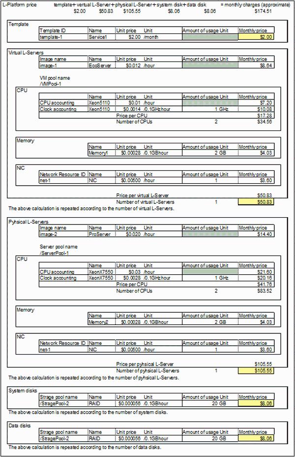
161
162 L-Platform usage fee (the estimated price) = monthly template price + monthly price for all L-Server + monthly price for all system disks + monthly price for all data disks Template monthly price = template unit price * monthly amount conversion Virtual L-Server monthly price = image unit price * monthly amount conversion +(CPU unit price * monthly amount conversion + CPU clock unit price * CPU clocks * monthly amount conversion) * number of CPUs + memory unit price * amount of memory * monthly amount conversion Physical L-Server monthly price = image unit price * monthly amount conversion +(CPU unit price * monthly amount conversion + CPU clock unit price * CPU clocks * monthly amount conversion) * number of CPUs + memory unit price * amount of memory * monthly amount conversion System disk monthly price = system disk unit price * amount of disk * monthly amount conversion Data disk monthly price = data disk unit price * amount of disk * monthly amount conversion NIC monthly charge = NIC unit price * used number of NICs * monthly amount conversion Estimated charges for snapshots Estimated charges for snapshots on the system disk = snapshot unit price * system disk capacity * monthly amount conversion Estimated charges for snapshots on the data disk = snapshot unit price * data disk capacity * monthly amount conversion - If the price is hourly basis, usage fee (the estimated price) is calculated for 24 hours * 30 days. - If the price is yearly basis, usage fee (the estimated price) is twelfth of that price. - Usage fee (the estimated price) is rounded to nearest hundredths of dollar (cent) when displayed. - Estimated charges for an L-Platform are displayed when an application is made to use an L-Platform, or when its configuration is changed. - Estimated charges for a snapshot are displayed when a snapshot of a virtual server is taken and when the snapshot is referenced Accounting Information File Format The accounting information of L-Platform templates is written to the accounting information file. The format of accounting information file is as follows. - Character code is UTF-8. - Each column is separated by a comma. - Comments cannot be written. - Character string data are enclosed by double quotations. When the double quotation is a character in a character string, enter two double quotations to escape it. - When a double quotation is set in a character string that is enclosed with double quotations, the single double quotation will be ignored
163 Example When the following string is entered in the accounting information file, the value will be "aaaaa"a". "aaaaa""a" When the following string is entered in the accounting information file, the value will be "aaaaaa". "aaa"aaa" Columns represented in an accounting information file are shown below. No Name Omit Explanation 1 Product ID No Specify ID that identifies the product. Register one product for each resource identifier. Specify 16 or less characters using alphanumeric characters, _(underline), or -(hyphen). 2 Priority No Specify the priority in a product. Multiple unit prices can be specified in a product, and the unit price with larger value has higher priority. (*1) The same priority cannot be set to the same product. Specify the numerical value from 0 to Start of applicable date 4 End of applicable date No Yes Specify start of applicable date. Format: YYYY-MM-DD Thh:mm:ss.SSSZ Example) Use T00:00: for the date and time 12:00A.M. and seconds on April 1, 2012 in time zone UTC+9:00 Specify end of applicable date. Format: YYYY-MM-DD Thh:mm:ss.SSSZ Example) Use T23:59: for the date and time 11:59 P.M. and seconds on March 31, 2013 in time zone UTC+9:00 Specify the date prior to the start of applicable date. 5 Category code No Specify the product category using following codes. - cpu: CPU - cpu clock: CPU clock - memory: memory capacity - vm: virtual L-Server - pm: physical L-Server - sys_disk: system disk capacity - disk: extension disk capacity - snapshot: snapshot - template: template - nic: NIC 6 Resource identifier No Specify information to identify the accounting target resource with 128 or less alphanumeric characters. Resource identifiers vary by the category. (*2) - cpu, cpu_clock, memory: VM pool name or sever pool name - vm: virtual L-Server image name - pm: physical L-Server image name - sys_disk: storage pool name
164 No Name Omit Explanation - disk: storage pool name - snapshot: storage pool name - template: template ID - nic: network resource ID 7 Unit code No Specify accounting unit using following codes. - year: yearly - month: monthly - hour: hourly 8 Unit price No Specify unit price. Specify 11 or less digits for the integer portion and 4 or less digit for the fractional portion. Specify the fractional currency unit (ex. cent) as 1 for U.S. dollar, euro, or Singapore dollar. Specify the currency unit as 1 for Japanese yen. (*3) Example) Specify 23 if the setting value is $0.23. Specify 23 if the setting value is Product name No Specify the name to distinguish the products using 128 or less characters. 10 Description Yes Specify the description of the product using 1024 or less characters. A comma that follows the name must be entered even when the specification is omitted. Example)...,Unit price,"product name", *1: An example of description is shown below assuming following settings. - Example of the setting for product ID "ME-0001" Data A Data B Product ID Priority Unit price Start of applicable date ME $ T00:00: None End of applicable date ME $ T00:00: T23:59: The unit price for product ID "ME-0001" is $2.00 on because only data A is applied. - The unit price for product ID "ME-0001" is $1.00 on because data B has higher priority even though both data A and data B are in the applicable period. - An example description of accounting information file "ME-0001",0," T00:00: ",,"memory","/VMPool","month",200,"Standard memory","standard memory" "ME-0001",1," T00:00: "," T23:59: ","memory","/ VMPool","month",100,"Standard memory(campaign)","standard memory(campaign)" *2: The value of the resource identifier can be obtained from the value of the corresponding XML tag of the template information list that is output in XML format by using the template information list display command. Refer to "9.12 cfmg_listtemplate (Displaying Template Information List)" in the "Reference Guide (Command/XML) CE" for information on how to use the template information list display command. The resource identifier for each category code and the corresponding template information (XML tag) are shown below. - Resource identifiers and corresponding template information (XML tag)
165 Category code Resource identifier Template information (XML tag) template Template ID <template><id> vm Virtual L-Server image name <image><imagename> pm Physical L-Server image name <image><imagename> cpu VM pool name or sever pool name <server><pool> cpu_clock VM pool name or sever pool name <server><pool> memory VM pool name or sever pool name <server><pool> sys_disk Storage pool name <server><storagepool> disk Storage pool name <vdisk><storagepool> snapshot Storage pool name <server><storagepool> and <vdisk><storagepool> nic Network resource ID <vnet><resourceid> Specify VM pool name, sever pool name and storage pool name in the format that start with / (slash). If the VM pool name, sever pool name or storage pool name are omitted, they are output to the template information as <pool /> or <storagepool />, respectively. In this case, refer to the resource pool and perform settings on the ROR Console Resource tab. Refer to the "User's Guide for Infrastructure Administrators (Resource Management) CE" for information on the ROR Console Resource tab. *3: The currency unit can be changed according to the currency unit setting. Specify the value multiplied by 10 raised to the power of the number of decimal places for the unit price in the accounting information file. Example: - Specify 1 as the unit price of currency unit 1 if the currency unit has no decimal places. - Specify 100 as the unit price of currency unit 1.00 if the currency unit has two decimal places. Refer to "8.7.2 Currency Information Settings" for information on how to set the currency unit. An example description of template information and corresponding accounting information is shown below. - Example of template information <?xml version="1.0" encoding="windows-31j"?> <templates> <template> <id>templateid1</id>... <vnets> <vnet> <resourceid>rormng_123</resourceid> </vnet> </vnets> <servers> <server> <pool>/vmhostpool</pool> <storagepool>/storagepool</storagepool>... <vdisks> <vdisk>... <storagepool>/storagepool2</storagepool>... </vdisk> </vdisks>
166 <image> <imagename>image1</imagename>... </image> </server> </servers> </template> </templates> - Example description of accounting information file "TP-0001",0," T00:00: ",,"template","templateId1","month",1000,"Web/DB Windows Server 2008 R2 Standard","Service Windows Server 2008 R2 Standard" "VM-0001",0," T00:00: ",,"vm","image1","month",500,"Windows Server 2008 R2 Standard","VM Windows Server 2008 R2 Standard" "CP-0001",0," T00:00: ",,"cpu","/VMHostPool","month",100,"Xeon5110","Xeon5110" "CL-0001",0," T00:00: ",,"cpu_clock","/VMHostPool","month", 50,"Xeon5110","Xeon5110" "ME-0001",0," T00:00: ",,"memory","/VMHostPool","month",200,"Standard memory","standard memory" "DI-0001",0," T00:00: ",,"disk","/StoragePool2","month",10,"normal disk","normal disk" "SD-0001",0," T00:00: ",,"sys_disk","/StoragePool","month",10,"normal disk","normal disk" "SS-0001",0," T00:00: ",,"snapshot","/StoragePool","hour",0.1,"snapshot disk","snapshot disk" "SS-0002",0," T00:00: ",,"snapshot","/StoragePool2","hour",0.1,"snapshot disk2","snapshot disk2" "NC-0001",0," T00:00: ",,"nic","rormng_123","hour",0.1,"Standard NIC","Standard NIC" Note - The accounting information will not be deleted from the product master automatically even after the end of applicable date. Reference to " Delete Accounting Information" to delete unnecessary accounting information. - If the end of applicable date is specified, prepare other accounting information of the same product ID without specifying the end of applicable date. - If the overcommit function is enabled, the category codes cpu_clock and memory will be calculated by default as CPU reserve performance and memory reserve capacity, respectively, and usage fee (the estimated price) will be displayed on the L-Platform management window. Refer to "8.7.1 Display Function Settings for Estimated Price" for information on charge settings when the overcommit function is enabled Operate Accounting Information This section explains how to operate the accounting information. The operation for the accounting information consists of registration, modification, deleting, and reference. Resister accounting information Register the accounting information when newly created L-Platform templates are enabled. The accounting information is set to the elements of L-Platform templates that are created. After finishing registration of the accounting information, enable the L-Platform templates. It is also possible to register accounting information for L-Servers that were imported into the system using the L-Server import command. Refer to " Register Accounting Information" for information on how to register the accounting information
167 Modify accounting information Modify the accounting information of the L-Platform templates that are already enabled. This corresponds to the case of setting limited time price for campaign or raising the price, for example. The price is modified to the accounting information of the L-Platform templates registered on the product master. It is also possible to modify accounting information for L-Servers that were imported into the system. Refer to " Modify Accounting Information" for information on how to modify the accounting information. Delete accounting information Delete the accounting information if all the following conditions are satisfied. - The L-Platform templates are disabled. - The log that shows the usage result of the corresponding L-Platform templates does not exist in the metering log. Refer to " Delete Accounting Information" for information on how to delete the accounting information. Refer also to "Appendix B Metering Log" for information on the metering log. Reference accounting information Reference the accounting information registered on the product master when calculating the accounting. Refer to " Reference Accounting Information" for information on how to reference the accounting information Register Accounting Information Methods for registering accounting information differ for L-Platform templates and L-Servers that were imported into the system. Register Accounting Information of L-Platform template Create new L-Platform templates, and set the accounting information to the elements of the L-Platform template that was created. After finishing the registration of the accounting information, enable the L-Platform templates. Follow the procedure below to register the accounting information. 1. Register new L-Platform templates. Refer to "8.3.1 Creating New L-Platform Template" in the "User's Guide for Infrastructure Administrators CE" for information on how to register L-Platform templates. 2. Obtain a list of the template information registered. Refer to "9.12 cfmg_listtemplate (Displaying Template Information List)" in the "Reference Guide (Command/XML) CE" for information on how to obtain the template information list. 3. Execute the output function of the product master maintenance command. The accounting information of the L-Platform templates registered on the product master will be output to the specified accounting information file by executing the output function of the product master maintenance command. Refer to "11.4 productmaintain (Product Master Maintenance)" in the "Reference Guide (Command/XML) CE" for information on the output function of the product master maintenance command. This operation is unnecessary for the initial registration. Create a new accounting information file from step Add the accounting information of the L-Platform templates to the output accounting information file based on the template information list. Specify a date prior to the L-Platform template enabled date as the start of applicable date in the accounting information to be added. Omit the end of applicable date. Refer to " Accounting Information File Format" for information on the accounting information file format. Example) Product ID Priorit y Unit price Start of applicable date Data A ID001 0 $ T00:00: None End of applicable date 5. Notify the tenant of the contents of the newly enabled L-Platform templates (L-Platform template name, summary of the L-Platform template, usage fee (the estimated price), start of applicable date, etc.)
168 6. Execute the register function of the product master maintenance command. Specify the accounting information file updated, and execute the product master maintenance command. Refer to "11.4 productmaintain (Product Master Maintenance)" in the "Reference Guide (Command/XML) CE" for information on the register function of the product master maintenance command. 7. Enable the L-Platform template. Enable the L-Platform template on the start of applicable date. Refer to "8.3.5 Publishing and Hiding L-Platform Template" in the "User's Guide for Infrastructure Administrators CE" for information on how to enable the L-Platform templates. Registering Accounting Information for L-Servers imported into the System Use the following procedures to import an L-Server into the system and register accounting information for the imported L-Server. 1. Use the L-Server import command to import the L-Server into the system. Refer to "10.5 cfmg_importlserver (Import L-Server)" in the "Reference Guide (Command/XML) CE" for information on how to use the L-Server import command. Note - If the <VM pool name> option is omitted when executing the L-Server import command, it will not be possible to register accounting information for the CPU, CPU clock or memory capacity. - If the <storage pool name> option is omitted when executing the L-Server import command, it will not be possible to register accounting information for system disk, data disk, and snapshot of the L-Server. - When an L-Server that has a snapshot is imported, it is not possible to register charge information for the snapshot collected before import. It is also not possible to output metering logs or tally usage charges for the snapshot collected before import. 2. Obtain the template information list that was automatically generated by the L-Server import command. The template information list can be obtained using the template information list display command. Refer to "9.12 cfmg_listtemplate (Displaying Template Information List)" in the "Reference Guide (Command/XML) CE" for information on how to use the template information list display command. 3. Point Check the following tags to distinguish between automatically generated templates: - Template ID (<template><id>): The template ID output when the L-Server import command is executed. - L-Server name (<template><description>): The L-Server name specified when the L-Server import command is executed. 4. Execute the output function of the product master maintenance command. The accounting information of the L-Platform templates registered on the product master will be output to the specified accounting information file by executing the output function of the product master maintenance command. Refer to "11.4 productmaintain (Product Master Maintenance)" in the "Reference Guide (Command/XML) CE" for information on the output function of the product master maintenance command. This operation is unnecessary for the initial registration. Create a new accounting information file from step Add the accounting information to the output accounting information file based on the template information list. When applying a start date for the accounting information to be added, specify a date/time prior to the date/time that the L-Server import command was executed. Omit the end of applicable date. Refer to " Accounting Information File Format" for information on the accounting information file format. Example) Product ID Priorit y Unit price Start of applicable date Data A ID001 0 $ T00:00: None End of applicable date
169 6. Execute the register function of the product master maintenance command. Specify the accounting information file updated, and execute the product master maintenance command. Refer to "11.4 productmaintain (Product Master Maintenance)" in the "Reference Guide (Command/XML) CE" for information on the register function of the product master maintenance command Modify Accounting Information Modify the accounting information of the L-Platform templates that are already enabled. This corresponds to the case of raising the price or setting limited time price for campaign. It is also possible to modify accounting information for L-Servers imported into the system. Follow the procedures below to modify accounting information for either L-Platform templates registered in the product master or L- Servers imported into the system. 1. Execute the output function of the product master maintenance command. The accounting information of the L-Platform templates registered on the product master will be output to the specified accounting information file by executing the output function of the product master maintenance command. Refer to "11.4 productmaintain (Product Master Maintenance)" in the "Reference Guide (Command/XML) CE" for information on the output function of the product master maintenance command. 2. Modify the price, or specify the time period of the output accounting information file. An example of the modification of the accounting information file is shown below. Specify future date to the modification date. a. Add the modified unit price data newly to change the unit price of the product that is already registered on the product master. Example) Modify the unit price of the product whose product ID is "ID001" to $2.10 from Before modification: Product ID Priori ty Unit price Start of applicable date Data A ID001 0 $ T00:00: None After modification: Product ID Priori ty Unit price Start of applicable date End of applicable date End of applicable date Data A ID001 0 $ T00:00: T23:59: Data B ID001 1 $ T00:00: None Set as follows for existing data A. - End of applicable date: Modify to the date just before the modification date. Set as follows for new data B. - Priority: Higher priority than the existing data A - Unit price: New unit price - Start of applicable date: Modification date - End of applicable date: Omit b. Add new data for the specific time period if a limited time price such as campaign price is to be registered. Example) Halve the price in the period between and Before modification: Product ID Priori ty Unit price Start of applicable date Data A ID001 0 $ T00:00: None After modification: End of applicable date Product ID Priori ty Unit price Start of applicable date End of applicable date
170 Data A ID001 0 $ T00:00: None Data B ID001 1 $ T00:00: T23:59: Do not modify existing data A. Set as follows for new data B. - Priority: Higher priority than the existing data A - Unit price: New unit price - Start of applicable date: Start date of the period - End of applicable date: End date of the period Refer to " Accounting Information File Format" for information on the accounting information file format. 3. Notify the tenant of the contents of the modified L-Platform templates (L-Platform template name, usage fee (the estimated price), start of applicable date, etc.). 4. Execute the register function of the product master maintenance command. Specify the accounting information file updated, and execute the product master maintenance command. Refer to "11.4 productmaintain (Product Master Maintenance)" in the "Reference Guide (Command/XML) CE" for information on the register function of the product master maintenance command. Note - If the applicable start date is not set to a future date and time, modify the charge information after the system has stopped. If system operation is not stopped, the pre-modification amounts may be displayed for the estimated charges and usage charges. - The displayed price does not change for the subscription from saved specifications if the specifications are saved before modifying the price. Notify the tenant of the cautions that the price will not be the price displayed on the L-Platform management window but be the modified price after the modification date Delete Accounting Information Delete the accounting information if the accounting calculation becomes unnecessary for the L-Platform templates or the L-Server imported into the system. The accounting information is unnecessary if all the following conditions are satisfied: - The L-Platform templates are disabled. - The log that shows the usage result of the corresponding L-Platform templates or L-Server imported into the system does not exist in the metering log. Follow the procedure below from disabling the L-Platform templates to deleting the accounting information. Begin from "Check Metering Log" for L-Servers imported into the system. Refer to "Appendix B Metering Log" for information on the metering log. Disable L-Platform templates 1. Notify to the tenant about the contents of the L-Platform templates to be disabled (L-Platform template name, usage fee (the estimated price), start of applicable date, etc.). 2. Disable the L-Platform templates on the date that was notified. Disable the L-Platform templates using the template management window of the ROR Console. Refer to "8.3.5 Publishing and Hiding L-Platform Template" in the "User's Guide for Infrastructure Administrators CE" for information on the setting for disabling the L-Platform template

171 Check Metering Log 1. Check that the log that shows the usage result of the corresponding L-Platform templates does not exist in the metering log. Output the metering log by the output metering logs command to check that no resource identifiers corresponding to the category code of that accounting information and no information for the item ID corresponding to that exists in the metering log. The correspondence relationships between category codes and resource identifiers in the accounting information and item IDs in the metering log are shown below. Accounting information Metering log Category code Resource identifier Item ID cpu VM pool name vm_pool Server pool name server_pool cpu_clock VM pool name vm_pool Server pool name server_pool memory VM pool name vm_pool Server pool name server_pool vm Image name image_name pm Image name image_name sys_disk Storage pool name storage_pool disk Storage pool name storage_pool snapshot Storage pool name storage_pool template Template ID base_template_id nic Network resource ID network_resource_id Delete accounting information 1. Execute the output function of the product master maintenance command. The accounting information of the L-Platform templates registered on the product master will be output to the specified accounting information file by executing the output function of the product master maintenance command. Refer to "11.4 productmaintain (Product Master Maintenance)" in the "Reference Guide (Command/XML) CE" for information on the output function of the product master maintenance command. 2. Delete accounting information that becomes unnecessary from the output accounting information file. 3. Execute the register function of the product master maintenance command. Specify the accounting information file updated, and execute the product master maintenance command. Refer to "11.4 productmaintain (Product Master Maintenance)" in the "Reference Guide (Command/XML) CE" for information on the register function of the product master maintenance command Reference Accounting Information Follow the procedure below to reference the accounting information registered on the product master
172 1. Execute the output function of the product master maintenance command. The accounting information of the L-Platform templates registered on the product master will be output to the specified accounting information file by executing the output function of the product master maintenance command. Refer to "11.4 productmaintain (Product Master Maintenance)" in the "Reference Guide (Command/XML) CE" for information on the output function of the product master maintenance command. 2. Reference the output accounting information file. Reference the accounting information file that was output by the output function of the product master maintenance command. Refer to " Accounting Information File Format" for information on the accounting information file format Calculation of Usage Charges This section explains how to calculate usage charges. Refer to "Appendix B Metering Log" for information on the metering log, which is the information upon which the calculation of usage charges is based Overview of Usage Charge Calculation When a user subscribes to or unsubscribes from an L-Platform, or performs operations such as starting or stopping an L-Server, these are recorded as operation logs in the metering log. Resource (L-Platform, L-Server, etc.) usage time is then aggregated from this operation log. Usage charges are calculated for each L- Platform based on the aggregated usage time, the amount of resources used, and the unit price in the charge information. When there is usage of resources for which a unit price has not been set in accounting information, calculation will be performed with the unit price for those products set as 0. The monthly usage charges are confirmed the day after the cut-off date set for the tenants, and then sent to the address Resource Usage Times Resource usage times include the time deployed and the time operated. These are aggregated based on the information in the metering log. Deployment time is the time between when the resource is deployed and when it is terminated. Operating time is the time between when the resource is started and when it is stopped. Usage time is aggregated according to the following rules: Usage time under one hour (in minutes) Each day's usage time is aggregated as minutes. Rounding Times are rounded off to the nearest minute. Times 30 seconds and over are counted as 1 minute. Times less than 30 seconds are counted as 0 minutes. The following shows an example of an L-Server deployed time and operated time. This example shows when an L-Server is added at 7:00, started at 7:40, stopped at 18:20, and then deleted at 19:
173 How to Charge for Resources Resources can be charged by a fixed rate or by the amount used. With fixed charging, the usage charges are charged according to a fixed fee rather than the usage time of the resources. With charging by the amount used, the usage charges are charged according to the usage time of the resources. Unit codes for the charge information are used when charging. Fixed charging is used when either year or month is specified as the unit code. Charging by amount is used when hour is specified as the unit code. The following table shows the relationships between the unit code specified in the charge information, the charging method, and the calculation of a month's usage charges: Unit codes charging method Usage charges for one month year Fixed charging Unit price / 12 (months) month Fixed charging Unit price hour Charge by amount Unit price / 60 (minutes) x usage time (minutes) x amount used Point The unit price, unit code, and 1 month's usage charges for each resource specified in the charge information are displayed as usage charge information for each month from the ROR console Accounting tab to Usage Charge Detail window. Refer to "12.3 Usage Charge Detail" in the "User's Guide for Infrastructure Administrators CE" for information on the Usage Charge Detail window. Also, tenant administrators can refer to the same information. Refer to "11.2 Usage Charge Detail" in the "User's Guide for Tenant Administrators CE" for information on the Usage Charge Detail window viewable by tenant administrators Resource Usage Amounts and Times If charging by amount is to be used for resources, the usage charge is determined by the amount of resources used and the time they are used for. The following table shows the relationship between the product categories for each resource, the amount of resources used, and the usage time: Resource Product category Resource usage amount Usage time L-Platform Template Total number of deployed L-Platforms L-Platform deployment time L-Server - Virtual L-Server Total number of deployed L-Servers L-Server deployment time - Physical L-Server CPU CPU CPU number Operating time of the L-Server
174 Resource Product category Resource usage amount Usage time CPU clock Use one of the following: - CPU performance (GHz) - CPU reserved performance (GHz) (*) Memory Memory capacity Use one of the following: Operating time of the L-Server - Memory (GB) - Memory reserved (GB) (*) System disk System disk capacity Disk size (GB) L-Server deployment time Data disk Data disk capacity Disk size (GB) Disk deployment time Snapshot Snapshot Disk size (GB) Snapshot deployment time NIC NIC The number used NIC deployment time * Note: This is the default value when overcommit is enabled on the virtual L-Server. These can be changed by changing the settings. Point Usage Charges for physical L-Servers. The calculation of Usage Charges for the CPU, CPU clock, and memory capacity of the physical L-Server are calculated using the values input into the L-Platform management window (input value). Also, a server that is close to the input value in the specified server pool will be deployed as the physical L-Server. For that reason, if charging for the physical L-Server, perform operations such as preparing multiple physical L-Servers that are close to the input value in the server pool. CPU usage charges The usage charge for the CPU is calculated based on the CPU and the CPU clock. The calculation formula is as follows: (CPU unit price / 60 (minutes) + CPU clock unit price / 60 (minutes) x CPU clock count / 0.1) x CPU count x usage time Example of Usage Charge Calculation Here we will describe an example of calculation, using an L-Platform with the configuration shown below

175 Configuration Charge information The charge information is as follows: Resource Resource identifier Unit codes Unit price template TE_01 month $
176 Resource Resource identifier Unit codes Unit price vm IM_01 hour $0.10 cpu /VMPool hour $0.001 cpu_clock /VMPool hour $0.002 memory /VMPool hour $0.001 sys_disk /StoragePool hour $0.001 disk /StoragePool hour $0.002 snapshot /StoragePool hour $0.001 nic net-1 hour $0.01 Operation Operations on the L-Platform are as follows: Date/time Operation :10:00 Deploy L-Platform :11:00 Start L-Server :10:00 Stop L-Server :11:00 Add L-Server :12:00 Take 1 snapshot of L-Server :13:00 Start L-Server :14:00 Start L-Server :00:00 Stop L-Server 1 and L-Server :01:00 Terminate L-Platform 1 Usage time The usage time for is resource is as follows: Resource Deployed time Running time L-Platform1 103 hours 51 minutes (6231 minutes) - L-Server1 103 hours 51 minutes (6231 minutes) 103 hours 46 minutes (6226 minutes) L-Server2 71 hours 50 minutes (4310 minutes) 71 hours 46 minutes (4306 minutes) system disk hours 51 minutes (6231 minutes) system disk2 71 hours 50 minutes (4310 minutes) Extension disk hours 51 minutes (6231 minutes) - Extension disk 2 71 hours 50 minutes (4310 minutes) - Snapshot 71 hours 49 minutes (4309 minutes) - NIC1 103 hours 51 minutes (6231 minutes) - NIC2 71 hours 50 minutes (4310 minutes) - Usage charges The usage charges for L-Platform 1 are as follows:
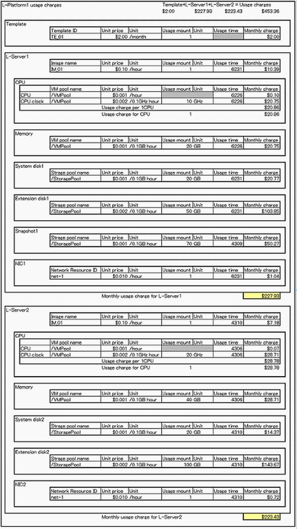
177
178 Point Fractions in usage charges When the calculations of usage charge produce a figure that includes fractions less than the lowest unit in the currency, the remainder is rounded off. L-Platform transfers When an L-Platform is moved, the usage charges for resources charged by amount are divided between the departure tenant and destination tenant, according to the amounts used. When resources are charged by a fixed amount, the departure tenant is billed Sending Usage charges The usage charges for the previous month confirmed the day after the cut-off date are attached as a usage charge file and sent to the address. The usage charge file is a zip file combining the usage charge list file and the usage charge detail file. The detail of this file is as follows: File File name Description Usage charges file YYYYMM_tenant_name[_date_deleted].zip File of usage charges for the tenant in zip format. YYYYMM is the date of the cut-off. "_date_deleted" is added when the tenant has already been deleted. Usage charge list file YYYYMM_tenant_name[_date_deleted].csv File in CSV format showing the tenant's previous month's usage charges plus the usage charges by the L-Platform they own. YYYYMM is the date of the cut-off. "_date_deleted" is added when the tenant has already been deleted. Usage charge detail file YYYYMM_L-PlatformID.csv File in CSV format showing the breakdown of usage charges for each L-Platform. YYYYMM is the date of the cut-off. Point Size of the usage charges file The size of usage charge files depends on the number of L-Platforms deployed for the tenant and the configuration used. For example, if 200 L-Platforms including two L-Servers are deployed, the file size is about 160 Kb Usage Charge List File The usage charge list file is a file in CSV format showing the tenant's previous month's usage charges plus the usage charges by the L- Platform they own. The output items are as follows: Item TenantName This is the tenant name. (*1) TenantDisplayName This is the display name. Note (*1) TenantDeletedDate Description This is the date and time the tenant was deleted. Output only if the tenant has already been deleted. Empty string is output if this has not been deleted. Format: YYYY-MM-DD HH:mm:ss.SSS (*1) Example: :59:
179 Date Item TotalChargeAmount FileVersion This is the cut-off date. Format:YYYY-MM (*1) Example: Description Total value of the usage charge for the tenant. The amounts are values, so they are not enclosed with double-quotes ("). Format:ZZZZZZZZZZZ9 (*2) Example:800 This is the version of the file. Fixed as 1.0. LplatformId This is the L-Platform ID. (*1) LplatformName This is the L-Platform name. (*1) LplatformDeletedDate ChargeAmount Date that the L-Platform was returned. Output only if the L-Platform has already been returned. Empty string is output if this has not been returned. Format: YYYY-MM-DD HH:mm:ss.SSS (*1) Example: :59: The amount of usage charges for each L-Platform. The amounts are values, so they are not enclosed with double-quotes ("). Format:ZZZZZZZZZZZ9 (*2) Example:1000 *1: Data enclosed with double-quotes ("). *2: The amount is shown only, without the currency symbol. The following is an example of file output: #TenantName,TenantDisplayName,TenantDeletedDate,Date,TotalChargeAmount,FileVersion,LplatformId,Lplat formname,lplatformdeleteddate,chargeamount "TNT00001","tenant01"," :30:40.001"," ",1800,"1.0","","","", "","","","",,"","TNT00001-LPlatform01","template-TNT00001-LPlatform01"," :30:40.001", 1000 "","","","",,"","TNT00001-LPlatform02","template-TNT00001-LPlatform02","", Usage charge Detail File The usage charge detail file is a file in CSV format showing the breakdown of usage charges for each L-Platform. The output items are as follows: Item TenantName This is the tenant name. (*1) TenantDisplayName This is the display name. Note (*1) TenantDeletedDate Description This is the date and time the tenant was deleted. Output only if the tenant has already been deleted. Empty string is output if this has not been deleted. Format: YYYY-MM-DD HH:mm:ss.SSS (*1) Example: :59: LplatformId This is the L-Platform ID. (*1) LplatformName This is the L-Platform name. (*1) LplatformDeletedDate Date that the L-Platform was returned. Output only if the L-Platform has already been returned. Empty string is output if this has not been returned
180 Date Item ChargeAmount FileVersion Format: YYYY-MM-DD HH:mm:ss.SSS (*1) Example: :59: This is the cut-off date. Format:YYYY-MM (*1) Example: Description The amount of usage charges for each L-Platform. The amounts are values, so they are not enclosed with double-quotes ("). Format:ZZZZZZZZZZZ9 (*1) Example:1000 This is the version of the file. Fixed as 1.0. ItemColumn1 This is a breakdown (item 1). The template name, virtual L-Server name, or physical L-Server name is output. ItemColumn2 This is a breakdown (item 2). The category of the resource. Empty string is output if this is for an L-Platform template, virtual L- Server, or physical L-Server. ItemColumn3 This is a breakdown (item 3). The image name or resource identifier is output. (*1) ItemColumn4 This is a breakdown (item 4). This is the unit corresponding to the unit price. A hyphen (-) is output if this is for an L-Platform template, virtual L-Server, or physical L-Server. UnitPrice This is the unit price. (*1) UsedFrequency This is the usage time. (*1) ItemAmount This is a breakdown of the amounts. Format:ZZZZZZZZZZZ9 (*2) Example:50 *1: Data enclosed with double-quotes ("). *2: The amount is shown only, without the currency symbol. The following is an example of file output: #TenantName,TenantDisplayName,TenantDeletedDate,LplatformId,LplatformName,LplatformDeleteDate,Date,C hargeamount,fileversion,itemcolumn1,itemcolumn2,itemcolumn3,itemcolumn4,unitprice,usedfrequency,item Amount "TNT00001","tenant01"," :30:40.001","TNT00002-LPlatform01","template-TNT LPlatform01"," :30:40.001"," ",351.20,"1.0","","","","","","", "","","","","","","",,"","Template","","TE_01","-","$ /month","1 month",20.00 "","","","","","","",,"","Virtual server(vservera)","","image001","-","$1.0000/h","20h",20.00 "","","","","","","",,"","Virtual server(vservera)","cpu","/vmpool","1cpus, 10GHz","$0.1000,$0.0100/0.1GHz-h","18h",19.80 "","","","","","","",,"","Virtual server(vservera)","memory size","/vmpool","10gb","$0.2000/0.1gbh","18h",36.00 "","","","","","","",,"","Virtual server(vservera)","disk size(system disk)","/ StragePool","10GB","$0.0080/0.1GB-h","18h",14.40 "","","","","","","",,"","Virtual server(vservera)","disk size(disk0)","/ StragePool","10GB","$0.0087/0.1GB-h","18h",15.8 "","","","","","","",,"","Virtual server(vservera)","disk size(disk1)","/ StragePool2","10GB","$0.0090/0.1GB-h","2h",1.80 "","","","","","","",,"","Virtual server(vservera)","snapshot(rormng_456)","/ StragePool","20GB","$0.0100/0.1GB-h","2h",0.40 "","","","","","","",,"","Virtual server(vservera)","snapshot(rormng_456)","/ StragePool2","10GB","$0.0100/0.1GB-h","2h",0.20 "","","","","","","",,"","Virtual server(vservera)","nic","rormng_123","1nics","$0.0500/h","20h",
181 "","","","","","","",,"","Virtual server(vserverb)","","image003","-","$1.0000/h","20h",20.00 "","","","","","","",,"","Virtual server(vserverb)","cpu","/vmpool","1cpus, 10GHz","$0.1000,$0.0100/0.1GHz-h","18h",19.80 "","","","","","","",,"","Virtual server(vserverb)","memory size","/vmpool","10gb","$0.2000/0.1gbh","18h",36.00 "","","","","","","",,"","Virtual server(vserverb)","disk size(system disk)","/ StragePool","10GB","$0.0080/0.1GB-h","18h",14.40 "","","","","","","",,"","Virtual server(vserverb)","disk size(disk0)","/ StragePool","10GB","$ /0.1GB-h","18h",15.8 "","","","","","","",,"","Virtual server(vserverb)","disk size(disk1)","/ StragePool2","10GB","$0.0090/0.1GB-h","2h",1.80 "","","","","","","",,"","Virtual server(vserverb)","snapshot(rormng_457)","/ StragePool","20GB","$0.0100/0.1GB-h","2h",0.40 "","","","","","","",,"","Virtual server(vserverb)","snapshot(rormng_457)","/ StragePool2","10GB","$0.0100/0.1GB-h","2h",0.20 "","","","","","","",,"","Virtual server(vserverb)","snapshot(rormng_458)","/ StragePool","20GB","$0.0100/0.1GB-h","18h",3.60 "","","","","","","",,"","Virtual server(vserverb)","snapshot(rormng_458)","/ StragePool2","10GB","$0.0100/0.1GB-h","18h",1.80 "","","","","","","",,"","Virtual server(vserverb)","nic","rormng_123","1nics","$0.0500/h","20h", 1.00 "","","","","","","",,"","Physical server(pservera)","","image002","-","$1.0000/h","20h",20.00 "","","","","","","",,"","Physical server(pservera)","cpu","/serverpool","1cpus, 10GHz","$0.1000,$0.0100/0.1GHz-h","18h",19.80 "","","","","","","",,"","Physical server(pservera)","memory size","/ ServerPool","10GB","$0.2000/0.1GB-h","18h",36.00 "","","","","","","",,"","Physical server(pservera)","disk size(system disk)","/ StragePool","10GB","$0.0800/0.1GB-h","18h",14.40 "","","","","","","",,"","Physical server(pservera)","disk size(disk0)","/ StragePool2","10GB","$0.0087/0.1GB-h","18h",15.80 "","","","","","","",,"","Physical server(pservera)","nic","rormng_123","1nics","$0.0500/h","20h",
182 Chapter 16 Monitoring Logs This chapter explains how to monitor logs Operation Logs This section explains the operation logs of Resource Orchestrator. Note - Operation logs should be used by only infrastructure administrators or administrators, as all user operations of Resource Orchestrator can be viewed. - Displaying resource names arranged in hierarchies is not supported Overview Provides the functions to record user operations as operation logs in Resource Orchestrator. Using this function, administrators can monitor the following information: - Time events were recorded in the operation logs - User ID - User group name - IP address - Status - Resource name - Operations The operation logs are output in the following formats: Date User Group IP Progress Resource Event Element Name Description Remarks Date User Group Time events were recorded in the operation logs User ID User group name The time events recorded in the operation logs are output in the local time. If daylight savings time (a regulation of time in summer) is set on the operating system, the time events are output in daylight savings time. Time events are output in the following format: YYYY-MM-DD HH:MM:SS.XXX The user ID of the logged in user is output. When a special administrator uses the command, a hyphen ("-") is output. The name of the user group name the logged in user belongs to is output. When the logged in user does not belong to a user group, a hyphen ("-") is output. IP IP address The IP addresses of the connected clients are output. Progress Status Starting and stopping of operations, and errors are output. The following statuses are output: - Start of operations
183 Element Name Description Remarks Starting(Operation_identifier) - End of operations Completed(Operation_identifier) - Errors during operations Error(Operation_identifier) Resource Event Resource name Operations A resource name and a resource identifier are output in the following format: - "Resource identifier(resource_name)" The parameters received by the manager are output. For the information that will be output, refer to " Scope of Operations Recorded in Operation Logs". Note - A hyphen ("-") may be output for an operation identifier. - For operations involving multiple resources, the same resource name as the one displayed in the Recent Operations on the ROR console and the event log is output in "Resource". Example Output the latest 1 day worth of data. For details on operations for operation logs, refer to "5.13 rcxadm logctl" in the "Reference Guide (Command/XML) CE". For the information that will be output, refer to " Scope of Operations Recorded in Operation Logs". >rcxadm logctl list -latest -duration 1D <RETURN> Date User Group IP Progress Resource Event :15: Starting(BX620-1_21) BX620-1_473(snap) l_servers create :15: Error(BX620-1_21) BX620-1_473(snap) l_servers create :26: Starting(BX620-1_25) BX620-1_510(snap) l_servers create :29: Completed(BX620-1_25) BX620-1_510(snap) l_servers create :15: admin Starting(BX620-1_35) BX620-1_510(snap) server_images snapshot :15: admin Completed(BX620-1_35) BX620-1_510(snap) server_images snapshot :16: admin Starting(BX620-1_36) BX620-1_510(snap) server_images restore :16: admin Completed(BX620-1_36) BX620-1_510(snap) server_images restore :17: admin Starting(BX620-1_37) BX620-1_510(snap) server_images destroy :17: admin Completed(BX620-1_37) BX620-1_510(snap) server_images destroy :19: admin Starting(BX620-1_38) BX620-1_744(image_test) server_images create :27: admin Completed(BX620-1_38) BX620-1_744(image_test) server_images create
184 :42: admin Starting(BX620-1_40) BX620-1_578(image_test) server_images destroy :42: admin Completed(BX620-1_40) BX620-1_578(image_test) server_images destroy :51: usera groupa Starting(BX620-1_41) BX620-1_806(LS_RT_A001) l_servers create :53: usera groupa Completed(BX620-1_41) BX620-1_806(LS_RT_A001) l_servers create :53: usera groupa Starting(BX620-1_42) BX620-1_806(LS_RT_A001) l_servers start :54: usera groupa Completed(BX620-1_42) BX620-1_806(LS_RT_A001) l_servers start :54: usera groupa Starting(BX620-1_43) BX620-1_806(LS_RT_A001) l_servers restart :55: usera groupa Completed(BX620-1_43) BX620-1_806(LS_RT_A001) l_servers restart :55: usera groupa Starting(BX620-1_44) BX620-1_806(LS_RT_A001) l_servers stop :56: usera groupa Completed(BX620-1_44) BX620-1_806(LS_RT_A001) l_servers stop :57: usera groupa Starting(BX620-1_46) BX620-1_806(LS_RT_A001) l_servers attach :58: usera groupa Completed(BX620-1_46) BX620-1_806(LS_RT_A001) l_servers attach :58: usera groupa Starting(BX620-1_47) BX620-1_806(LS_RT_A001) l_servers detach :59: usera groupa Completed(BX620-1_47) BX620-1_806(LS_RT_A001) l_servers detach :59: usera groupa Starting(BX620-1_48) BX620-1_806(LS_RT_A001) l_servers migrate :00: usera groupa Completed(BX620-1_48) BX620-1_806(LS_RT_A001) l_servers migrate :01: usera groupa Starting(BX620-1_50) BX620-1_806(LS_RT_A001) l_servers update :02: usera groupa Completed(BX620-1_50) BX620-1_806(LS_RT_A001) l_servers update :04: usera groupa Starting(BX620-1_57) BX620-1_806(LS_RT_A001) l_servers destroy :05: usera groupa Completed(BX620-1_57) BX620-1_806(LS_RT_A001) l_servers destroy :35: usera groupa Starting(BX620-1_117) BX620-1_954(LS_RT_A001) folders move_resource :35: usera groupa Completed(BX620-1_117) BX620-1_954(LS_RT_A001) folders move_resource :04: admin Starting(BX620-1_570) BX620-1_2193(master-52) l_servers convert :04: admin Completed(BX620-1_570) BX620-1_2193(master-52) l_servers convert :05: admin Starting(BX620-1_571) BX620-1_2193(master-52) l_servers revert :05: admin Completed(BX620-1_571) BX620-1_2193(master-52) l_servers revert Note The starting point (Starting) of recording for each operation is when the operation is displayed in the Recent Operations on the ROR console
185 Usage Method This section explains the methods for configuring and operating operation logs. Perform the following procedure: 1. Disk space estimation Infrastructure administrator (infra_admin) estimates the disk size to use for storing operation logs. Estimate the amount of disk space using the following formula, and then decide the number of days to retain operation logs. {(Number_of_operations_of_the_resource_in_1_day) * (Number_of_target_resources) * 1(KB)} * (retention_period) Example Disk space when estimating that the retention period is 180 days (by default), the target resource is operated 4 times, and the number of target resources is 256 Retention period Necessary Disk Space Formula 180 days worth Approx. 185 MB 4 * 256 * 1 * 180 = (KB) 2. Check the settings in the [Date and Time properties] dialog of the operating system Check whether the following tabs of the OS are configured correctly. If the settings are incorrect, set them correctly. - [Date and Time] tab - [Time Zone] tab - [Internet Time(or the Network Time Protocol)] tab 3. Configure the retention period of operation logs Execute the rcxadm logctl set command, to configure the retention period for operation logs. For details on the rcxadm logctl set command, refer to "5.13 rcxadm logctl" in the "Reference Guide (Command/XML) CE". 4. Start recording of the operation log Execute the rcxadm logctl start command to start recording the operation log. When the rcxadm logctl start command is executed, the operation logs will be recorded for the configured retention period from the date recording of operation logs is started. Days when no events occur, or days when recording is not possible due to the manager being stopped are not counted as dates for recording. Note - When the settings of the OS [Date and Time Properties] dialog have been changed after starting the recording of operation logs It may not be possible to correctly display or delete the operation logs. - When changing the settings of the OS [Date and Time Properties] dialog after starting the recording of operation logs Refer to " Retention". - When a Cloud Edition license has been registered When starting the manager, recording of operation logs is started automatically
186 Retention This section explains the retention of operation logs. - Periodic deletion Due to extended periods of operation or modification of retention periods, operation logs which have exceeded a certain retention period are periodically deleted. The timing of deletion (based on retention period checks) is set to take place as the first operation after the date changes. Note - The recording period is the retention period + 1. After periodic deletion is performed, the recording period will be equal to the retention period. - Periodic deletion is executed when the next recording is started (the first recording after the date changes), and operation logs will be deleted in chronological order. - Deletion Users can delete unnecessary operation logs by defining a retention period. - Backup and Restore Use the following procedure for backup and restoration of operation logs. - Backup 1. Confirm the "retention folder" for the operation logs. 2. Stop recording operation logs. 3. Back up the "retention folder" confirmed in step Start recording operation logs. - Restore 1. Confirm the "retention folder" for the operation logs. 2. Stop recording operation logs. 3. Restore the backed-up folder into the "retention folder" confirmed in step Start recording operation logs. - Modification of the settings in the [Date and Time properties] dialog after starting the recording of operation logs Use the following procedure to make changes. 1. Stop recording operation logs. 2. Display the operation logs and back up the necessary portions from the records. 3. Confirm the "retention folder" for the operation logs. 4. Empty the "retention folder" by moving all files in the "retention folder" checked in step 3 to a new location. 5. Modify the settings in the [Date and Time properties] dialog. 6. Start recording operation logs. For details on operations for operation logs, refer to "5.13 rcxadm logctl" in the "Reference Guide (Command/XML) CE". Note - Once recording operations are stopped, user operations are not recorded until the recording of logs is started again
187 - Performing this procedure resets the recording period of operation logs to Scope of Operations Recorded in Operation Logs The scope of operations recorded in operation logs and the character strings displayed in the Event column are as indicated below. Table 16.1 Scope of Operations L-Server Image L-Platform Tenant Resource Type Action Strings Displayed in the Event Column Resource Folders Role Creation Deletion Modification Powering on Powering off Restarting Disk addition Disk detachment Folder migration Migration Physical L-Server configuration Transmission of network information to physical L- Servers Conversion Reversion Creation Deletion Restore Snapshot collection Creation Deletion Modification Create Deletion Modification Creation Deletion Modification l_servers create l_servers destroy l_servers update l_servers start l_servers stop l_servers restart l_servers attach l_servers detach folders move resource l_servers migrate l_servers set_attrs l_servers setup l_servers convert l_servers revert server_images create server_images destroy server_images restore server_images snapshot l_platforms create l_platforms destroy l_platforms update tenants create tenants destroy tenants update folders create folders destroy folders update Creation roles create (*) Deletion roles destroy Modification roles update (*) * Note: Detail informaition separated by commas is added to the end of the records if the -verbose option is specified when executing rcxadm logctl list command. For details on the rcxadm logctl list command, refer to "5.13 rcxadm logctl" in the "Reference Guide (Command/XML) CE". The output format and example are as follows
188 Output format roles create,baserole="basic role name"[[,name="operation group name",authority="operation name[,...]"]...] roles update[,baserole="basic role name"][[,name="operation group name",authority="operation name[,...]"]...] Output example roles create,baserole="infra_admin",name="lplatform",authority="showlog",name="lserver", Authority="maintenance",name="Image",Authority="management",name="Console",Authority="home,dashboa rd,resource,template,lplatform,request,tenant,charge,account" roles update,name="lplatform",authority="showlog",name="lserver",authority="maintenance", name="console",authority="home,dashboard,charge,account" For details on the "Basic role name", "Operation group name", and "Operation name", refer to "15.8 Roles" in the "Reference Guide (Command/XML) CE" Audit Logs This section explains audit logs. By looking up audit logs, it is possible to find out who performed what operation when Configuration Management Audit Log This section explains the configuration management audit log. The file name, file size, and number of generations of the audit log are shown below: Log name Description File size Number of generations vsys_audit_log Audit logs are output to this log. 10 MB 10 generations (*) * Note: If the number of saved generations exceeds 10 generations, old generations will be deleted, starting with the oldest generation. The file size and the number of generations to be saved can be changed. Refer to "Procedure for changing the size of the file" and "Procedure for changing the number of generations to be saved" for details. With default settings, audit logs will be held for approximately 50 days if 10 people use this product for approximately one hour per day per person. If necessary, back up audit logs at appropriate intervals according to the usage frequency. The names of the files to be backed up are shown below: vsys_audit_log.[n] (where "n" is the generation number) Example: To back up three generations' worth of files, the names of the files to be backed up are as follows: - vsys_audit_log.1 - vsys_audit_log.2 - vsys_audit_log.3 Output Destination The log output destinations are shown below: [Windows Manager] Output folder Installation_folder\RCXCFMG\logs Output destination file vsys_audit_log.[n] (n is the number of generations) [Linux Manager] Output folder /var/opt/fjsvcfmg/logs Output destination file vsys_audit_log.[n] (n is the number of generations)
189 Output format Audit logs are CSV files where the following items are output in the following order: Output format <date/time when the operation was performed>,<user ID>,<organization ID>,<operation ID>,<parameters>,<operation result> Item date/time when the operation was performed user ID organization ID YYYY-MM-DD HH:MM:SS.sss (local time). Description The user ID of the user that executed the operation. The organization ID of the user that executed the operation. operation type A string indicating the content of the operation. (*) parameters operation result * Note: The operation types are as follows: The parameters specified by the request. "SUCCESS" if the operation was successful and "FAILURE" if the operation failed. Operation type AccessControl#evaluate AccessControl#getAuthority DeployMaster#delete DeployMaster#getDetail DeployMaster#getSaveList DeployMaster#getTemplate DeployMaster#save DeployMaster#setStatus Event#notify EventLog#getList Images#changeShow Images#getDetail Images#getList Images#getServerType Images#register Images#search Images#unregister Images#update Network#addCategory Network#deleteCategory Network#getCategoryList Network#getList Network#getRulesetList Checking access permissions. Description Obtaining information about resource operation privileges for a user. Deleting configuration information. Obtaining detailed configuration information. Obtaining a list of configuration information. Obtaining a deployment master from an L-Platform template. Saving configuration information. Setting the status of configuration information. Notifying events that occurred on a server. With the current version, changes to the power status, migration, reconfiguring, pool information, events are notified. Obtaining a list of event logs. Changing whether images are displayed. Obtaining detailed image information. Obtaining a list of images registered. Obtaining a list of L-Server Templates. Registering image information with this product. Searching image information. Deregistering image information from this product. Updating image information. Registering a network resource type. Deleting a network resource type. Obtaining a list of network types. Obtaining a list of networks. Obtaining a list of rulesets
190 Operation type Network#detailRuleset Parameters#delete Parameters#getDetail Parameters#getList Parameters#set Softwares#create Softwares#delete Softwares#getDetail Softwares#getList Softwares#update Templates#changeShow Templates#deletePublic Templates#getDetail Templates#importPublic Templates#search Templates#updatePublic VDisk#getList VServer#addPatch VServer#attach VServer#backup VServer#cancelError VServer#changeSpec VServer#cloning VServer#create VServer#deletePatch VServer#detach VServer#getBackupList VServer#getInitPW VServer#release VServer#removeBackup VServer#restore VServer#search VServer#start VServer#stop VSYS#addNetwork VSYS#changeOrg VSYS#convertFolder VSYS#delete VSYS#deleteLServer Obtaining detailed ruleset information. Deleting parameter information. Obtaining detailed parameter information. Obtaining a list of parameter information. Description Registering or updating parameter information. Registering software information. Deleting software information. Obtaining detailed software information. Obtaining a list of software. Updating software information. Changing the settings as to whether L-Platform templates can be displayed. Deleting L-Platform templates. Obtaining detailed L-Platform template information. Registering L-Platform template information. Searching an L-Platform template. Updating templates Obtaining a list of existing disks. Registering patch information. Adding an expansion disk. Creating a snapshot. Releasing the error status of snapshots or restorations. Changing server performance. Collecting a cloning image from a deployed server. Adding a server. Deleting patch information. Deleting an expansion disk. Obtaining a list of snapshots. Obtaining the initial password for a server. Returning a server. Deleting a snapshot. Restoring a server. Obtaining server information. Starting a server. Stopping a server. Adding a segment to an L-Platform. Changing a user ID or organization ID for an L-Platform. Converting a system deployed with Systemwalker Software Configuration Manager V14.1 to an L-Platform for this product. Deleting an L-Platform from just the resource window after deleting failed, etc. Deleting a server included in an L-Platform from the L-Platform
191 Operation type VSYS#deleteNetwork VSYS#deploy VSYS#flowCancel VSYS#flowCancelRetry VSYS#flowDeploy VSYS#flowEnableDeploy VSYS#flowEnableRelease VSYS#flowEnableUpdate VSYS#flowError VSYS#flowForward VSYS#flowRejectApplication VSYS#flowRelease VSYS#flowReleaseApplication VSYS#flowReleaseForward VSYS#flowSaveCancel VSYS#flowUpdate VSYS#getConfigurations VSYS#getCurrency VSYS#getDetail VSYS#getHostnameCounter VSYS#getList VSYS#getLoginDate VSYS#getOperationLNetDevResult VSYS#getPoolList VSYS#getTask VSYS#getTenantList VSYS#importLServer VSYS#lock VSYS#operateLNetDev VSYS#recoverDisk VSYS#recoverNet VSYS#recoverNic VSYS#recoverServer VSYS#recoverSystem VSYS#release VSYS#resetHostnameCounter VSYS#setChangeInfo VSYS#setDisplayStatus Deleting a segment from an L-Platform. Deploying an L-Platform. Description Canceling the application to deploy an L-Platform or change a configuration. Canceling the flow for saving a configuration and then making another application. Deploying an L-Platform. (For flows: no operation after authorization.) Deploying an L-Platform. (For flows: operation to perform after authorization.) Returning all L-Platforms as a batch. (For flows: operation to perform after authorization.) Reconfiguring an L-Platform. (For flows: operation to perform after authorization.) Executing post-processing when an error has occurred with an application flow for deploying an L-Platform or changing a configuration. Applying to deploy an L-Platform or change a configuration. Rejecting deployment application. Returning all L-Platforms as a batch. (For flows: no operation after authorization.) Applying to return an L-Platform. Setting the status of a return application to "forwarding complete". Canceling the application to deploy an L-Platform or change a configuration. Reconfiguring an L-Platform. (For flows: no operation after authorization.) Obtaining configuration information. Obtaining product currency information. Obtaining detailed information for an L-Platform. Obtaining a list of host name serial number counters. Obtaining a list of L-Platforms. Obtaining the date/time when the user logged in to the L-Platform Manager View. Obtaining the operation logs for the server load balancer. Obtaining a list of resource pools for ServerView Resource Orchestrator. Obtaining task information. Obtaining a list of tenants. Importing an L-Server under resource management to an L-Platform. Locking an L-Platform. Executing server load balancer operations. Recovering a disk. Recovering a network segment. Recovering an NIC. Recovering a server. Recovering an L-Platform. Returning all L-Platforms as a batch. Resetting the host name serial number counter. Recovering an L-Platform name, server name, or server specification. Changing the status of an L-Platform
192 Operation type VSYS#setLoginDate VSYS#setRecoverInfo VSYS#setServerStatus VSYS#setUndeploy VSYS#start VSYS#startServers VSYS#stop VSYS#stopServers VSYS#syncServerStatus VSYS#syncSpec VSYS#unlock VSYS#update VSYS#updateLNetDev VSYS#updateRemarks Description Updating the date/time when the user logged in to L-Platform Manager View. Recovering a resource ID or disk number. Recovering the status of a server. Changing the status of an L-Platform, server or disk to "undeployed". Starting the servers in an L-Platform as a batch. Starting the servers for multiple tenants as a batch. Stopping the servers in an L-Platform as a batch. Stopping the servers for multiple tenants as a batch. Synchronizing server power statuses in a batch. Synchronizing server performance information with the actual state. Unlocking an L-Platform. Reconfiguring an L-Platform. Updating the parameters for the firewall and server load balancer. Changing the L-Platform remarks column input values after deploying. Procedure for changing output destination Use the following procedure to change the audit log output destination. 1. Rewrite the settings file. The following table shows the settings file and the location to change: [Windows Manager] Log name Settings file Location to change (one location) vsys_audit_log [Linux Manager] Installation_folder\RCXCFMG\config \vsys_log4j.xml <param name="file" value="c:\programdata\fujitsu \SystemwalkerCF-MG\logs\vsys_audit_log" /> Log name Settings file Location to change (one location) vsys_audit_log /etc/opt/fjsvcfmg/config/vsys_log4j.xml <param name="file" value="/var/opt/fjsvcfmg/logs/ vsys_audit_log" /> 2. Restart the manager. Refer to "2.1 Starting and Stopping Managers" for information on how to Restart the manager. Procedure for changing the size of the file Use the following procedure to change the audit log file size. 1. Rewrite the settings file. The location to change is shown below: [Windows Manager] Log name Settings file Location to change (one location) vsys_audit_log Installation_folder\RCXCFMG \config\vsys_log4j.xml Change the underlined part of the <param name="maxfilesize" value="10mb" /> element under the <appender name="auditfileout"
193 Log name Settings file Location to change (one location) [Linux Manager] class="org.apache.log4j.rollingfileappender"> element to the desired value. Example: value="100mb" (to change the size of the audit log file to 100 MB) Log name Settings file Location to change (one location) vsys_audit_log /etc/opt/fjsvcfmg/config/ vsys_log4j.xml Change the underlined part of the <param name="maxfilesize" value="10mb" /> element under the <appender name="auditfileout" class="org.apache.log4j.rollingfileappender"> element to the desired value. Example: value="100mb" (to change the size of the audit log file to 100 MB) 2. Restart the manager. Refer to "2.1 Starting and Stopping Managers" for information on how to Restart the manager. Procedure for changing the number of generations to be saved Use the following procedure to change the number of audit log generations to be saved. 1. Rewrite the settings file. The location to change is shown below: [Windows Manager] Log name Settings file Location to change (one location) vsys_audit_log [Linux Manager] Installation_folder\RCXCFMG \config\vsys_log4j.xml Change the underlined part of the <param name="maxbackupindex" value="9" / /> element under the <appender name="auditfileout" class="org.apache.log4j.rollingfileappender"> element to the desired value. Example: value="99" (to change the number of audit log generations to 100) Log name Settings file Location to change (one location) vsys_audit_log /etc/opt/fjsvcfmg/config/ vsys_log4j.xml Change the underlined part of the <param name="maxbackupindex" value="9" / /> element under the <appender name="auditfileout" class="org.apache.log4j.rollingfileappender"> element to the desired value. Example: value="99" (to change the number of audit log generations to 100) 2. Restart the manager. Refer to "2.1 Starting and Stopping Managers" for information on how to Restart the manager
194 Audit Logs of Output by the Tenant Management, Accounting and System Condition This section explains audit logs of output by the tenant management, accounting and system condition functions. Point - If L-Platform Management is operated, audit logs will be output to Configuration Manager. Refer to " Configuration Management Audit Log" for details. - Audit logs relating to the registration, modification or deletion of infrastructure administrators, infrastructure operators, infrastructure monitors, administrators, operators and/or monitors can be checked in the directory service access log. When the directory service that is included with ServerView Operations Manager(hereinafter SVOM) is used, the storage locations and file names of access logs are as follows. [Windows Manager] SVOM installation folder\serverview Suite\opends\logs\access [Linux Manager] /opt/fujitsu/serverviewsuite/opends/logs/access Output format Audit logs are CSV files where the following items are output in the following order: Output format operation date/time,user ID,tenant name,operation type,operation information,operation result Item operation date/time user ID tenant name operation type operation information operation result Description The date/time when the operation was performed. The date/time is output using the following format: YYYY-MM-DD HH:MM:SS.sss (local time) The user ID of the user that performed the operation. Fixed as ctmgadm for command operations. The tenant name of the user that executed the operation. Fixed as ctmgadm for the infrastructure administratrative role or multiple roles users. The type of the operation performed. Refer to "Operation types and operation information" for details. Detailed information for the operation type. Refer to "Operation types and operation information" for details. The result of the operation performed. One of the following values is output: SUCCESS: When the operation was successful FAILURE: When the operation failed Output files Audit logs are output to the following files:
195 Function Tenant management (GUI operations from the ROR Console) Tenant management (creating users from the ROR Console: Provisional account registration method) Accounting Accounting (GUI operations from the ROR Console) Accounting (Published API operation) System condition Output file [Windows Manager] Installation_folder\RCXCTMG\SecurityManagement\log\ctsec_audit_a.log [Linux Manager] /var/opt/fjsvctsec/log/ctsec_audit_a.log [Windows Manager] Installation_folder\RCXCTMG\SecurityManagement\log\ctsec_audit_s.log [Linux Manager] /var/opt/fjsvctsec/log/ctsec_audit_s.log [Windows Manager] Installation_folder\RCXCTMG\Charging\log\ctchg_audit.log [Linux Manager] /var/opt/fjsvctchg/log/ctchg_audit.log [Windows Manager] Installation_folder\RCXCTMG\Charging\log\charging_audit.log [Linux Manager] /var/opt/fjsvctchg/log/charging_audit.log [Windows Manager] Installation_folder\RCXCTMG\Charging\log\accounting_audit.log [Linux Manager /var/opt/fjsvctchg/log/accounting_audit.log [Windows Manager] Installation_folder\SWRBAM\CMDB\FJSVcmdbm\var\log\audit\uigui\cmdb_audit.log [Linux Manager] /opt/fjsvcmdbm/var/log/audit/uigui/cmdb_audit.log Procedure for changing the file size and the number of generations held By default, audit log files are rotated when they reach 10 MB. Also, the number of saved generations becomes 11. To change the maximum size of audit log files or the maximum number of generations held, perform the following procedure: 1. Stop the manager. Refer to "2.1 Starting and Stopping Managers" for information on how to stop the manager. 2. Edit the appropriate items in the following definition files: - Definition files Function Tenant management (GUI operations from the ROR Console) Tenant management (creating users from the ROR Console: Provisional account Definition file [Windows Manager] Installation_folder\RCXCTMG\conf\auditsecalog4j.xml [Linux Manager] /etc/opt/fjsvctmg/conf/auditsecalog4j.xml [Windows Manager] Installation_folder\RCXCTMG\conf\auditsecslog4j.xml [Linux Manager] /etc/opt/fjsvctmg/conf/auditsecslog4j.xml
196 Function registration method) Accounting Accounting (GUI operations from the ROR Console) Accounting (Published API operation) System condition Definition file [Windows Manager] Installation_folder\RCXCTMG\conf\auditchglog4j.xml [Linux Manager] /etc/opt/fjsvctmg/conf/auditchglog4j.xml [Windows Manager] Installation_ folder\rcxctmg\conf\auditchgguilog4j.xml [Linux Manager] /etc/opt/fjsvctmg/conf/auditchgguilog4j.xml [Windows Manager] Installation_ folder\rcxctmg\conf\auditacntlog4j.xml [Linux Manager] /etc/opt/fjsvctmg/conf/auditacntlog4j.xml [Windows Manager] Installation_folder\SWRBAM\CMDB\FJSVcmdbm\CMDBConsole\WEB-INF \classes\log4j.properties [Linux Manager] /opt/fjsvcmdbm/cmdbconsole/web-inf/classes\log4j.properties - Setting items Setting item MaxFileSize MaxBackupIndex Description This item sets the maximum size of audit log files. The file size can be specified using a combination of an integer greater than 0 and a unit (KB, MB or GB). (*1), (*2) Example: <param name="maxfilesize" value="500kb"/> This item sets the maximum number of generations of the audit log file. An integer greater than 0 can be specified. (*1) Example: <param name="maxbackupindex" value="50"/> *1: Do not specify decimal fractions. Also, do not leave a blank space. *2: Do not specify a maximum file size that is larger than the size of the disk. Conversely, do not set values that are too small for the maximum file size, or else the logs will be overwritten frequently. 3. Start the manager. Refer to "2.1 Starting and Stopping Managers" for information on how to start the manager. Operation types and operation information The following table shows the operation types and operation information that are output to audit logs: Function Operation type Content Operation information (*1) Tenant management (GUI operations from the ROR Console) registuser Notify user registration "mail=""xxx@com""" createuser Create users "userid=""<user ID of the user created>""&mail=""xxx@com"" &lastname=""<last name>""&firstname=""<first name> ""&auth=""<role name >(*8)"" &explanation=""xxxx""&corporatename=""fujitsu"" &emergencymail=""yyy@com""&emergencytel=""0000"""
197 Function Operation type Content Operation information (*1) (only if the infrastructure administrator performed or the tenant administrator performed by the direct registration method) deleteuser Delete users "userid=""<user ID of the user deleted>""" updateuser listuser Update user information Get a list of user information "userid=""<user ID of the user updated>""&mail=""xxx@com"" &lastname=""<last name>""&firstname=""<first name>""" &auth=""<role name>(*9)"" &explanation=""xxxx""&corporatename=""fujitsu"" &emergencymail=""yyy@com""&emergencytel=""0000""" None. moveuser Relocate users "userid=""<user ID of the user that has been relocated>""&oldorgid=""<name of the original tenant>"" &neworgid="" name of the tenant to which the user has been relocated"" updatepassword Update passwords "userid=""<user ID of the user whose password has been updated>"" createorg (*2) (*3) Create a tenant - With default setting "orgid=""<tenant name of the tenant that has been updated>""&orgname=""<tenant name>"" &mail=""xxx@com""&globalpool=""<global pool that has been set>""" - With calculation of Usage Charges, following items will be added to output &cutoffdate =""< Cutoff date>""&accountingmail=""< address where usage charges are sent>"" - With tenant of unique application process, following items will be added to output &applicationprocess=""workflow.policy=default custom,workflow.subscribe=infra-tenant infra tenant,workflow.reconfigure=infra-tenant infra tenant,workflow.unsubscribe=infra-tenant infra tenant"" deleteorg (*3) updateorg (*2) (*3) Delete tenants Update tenant information "orgid=""<tenant name of the tenant that has been deleted>""" - With default setting "orgid=""<tenant name of the tenant that has been updated>""&orgname=""<tenant name>"" &mail=""xxx@com""&globalpool=""<global pool that has been set>""" - With calculation of Usage Charges, following items will be added to output &cutoffdate =""< Cutoff date>""&accountingmail=""< address where usage charges are sent>"" - With tenant of unique application process, following items will be added to output &applicationprocess=""workflow.policy=default custom,workflow.subscribe=infra-tenant infra
198 Function Operation type Content Operation information (*1) Tenant management (creating users from the ROR Console: Provisional account registration method) listorg Get a list of tenant information tenant,workflow.reconfigure=infra-tenant infra tenant,workflow.unsubscribe=infra-tenant infra tenant"" None. createuser Create users "userid=""<user ID of the user created>""&mail=""xxx@com"" &lastname=""<last name>""&firstname=""<first name>""""&auth=""<role name>(*10)"" &explanation=""xxxx""&corporatename=""fujitsu"" &emergencymail=""yyy@com""&emergencytel=""0000""" Accounting updatepmaster Update product master Accounting (GUI operations from the ROR Console) listpmaster updatemlogsch listmlogsch listmeteringlog deletemlog getcurrencyunit updatecurrency Unit resetcurrencyun it listlplatformcha rge getdetailcharge listtenantcharge listlplatformcha rgebytenant Get a list of product master Update periodic log schedule settings Get a list of periodic log schedule settings Get a list of metering logs Delete metering logs Obtain currency unit settings Update currency unit settings Initialize currency unit settings Get a list of usage charge for each L- Platform Get a breakdown of L-Platform usage charges Get a list of usage charge for each tenant Get a list of usage charge for each L- Platform under the specified tenant None. None. "use=""yes no""&time=""<time of output of periodic log>""&type=""<frequency of output of periodic log>""&day=""<day of output of periodic log>""" "use=""yes no""&time=""<time of output of periodic log>""&type=""frequency of output of periodic log""&day=""<day of output of periodic log>""" "start=""<start date of the acquisition period>""&end=""<end date of the acquisition period>"" &type=""event period""" "retention=""<log entry retention period>""" None "currencycode=""currency code""" None None. None. None. None
199 Function Operation type Content Operation information (*1) downloadfile File download "target=""lplatformchargelist DetailCharge TenantChargeList LplatformChargeListByTenant""" Accounting (Published API operation) getresourceusa ge getusagepoint Get resource usage Get usage frequency None. None. registerusagepoi nt Register usage frequency (*4) "date=""<date of data registered>(*5)""&id=""<l-platform ID>""&name=""<L-Platform name>""&tenantname=""<tenant name of managed tenant>""&tenantdeletedate=""<date when managed tenant was deleted>(*6)""" getdailycharge Get daily usage charges None. registerdailycha rge Register daily usage charges (*4) "date=""<date of data registered>""&id=""l-platform ID""&name=""<L-Platform name>""&tenantname=""<tenant name of managed tenant>""&tenantdeletedate=""<date when managed tenant was deleted>""" getmonthlychar ge Get usage charges None. registermonthly Charge Register monthly usage charges (*4) "date=""<date of data registered>""&id=""l-platform ID""&name=""<L-Platform name>""&tenantname=""<tenant name of managed tenant>""&tenantdeletedate=""<date when managed tenant was deleted>""" gettenants Get tenant information None. System condition (*4) dispusagestatus Display usage condition None. *1: If a value is not set for an item, """" is output. An example is shown below.... &globalpool=""""... *2: If multiple global pools have been set, the global pools are output separated by commas. An example is shown below....&globalpool=""/addresspool,/imagepool""... *3: For the operation result of createorg, deleteorg, or updateorg, the processing result will be output. Use the operation log (resource operation) to check the actual processing result. Refer to "16.1 Operation Logs" for information on how to check the operation log (resource operation). *4: Multiple lines may be output each time there is a registration operation. *5: Output is in the format yyyy-mm-dd (for example, April 1, 2012 is output as ). *6: Output is in the format yyyy-mm-dd THH:mm:ss.SSSZ (for example, 12:00 A.M. and seconds on April 1, 2012 in time zone UTC+9:00 is output as T00:00: ). *7: Audit logs for usage condition are output only when operations are performed from the ROR Console. *8: tenant_admin, tenant_operator, tenant_monitor, tenant_user, or names of roles created from copies of these. *9: infra_admin, infra_operator, administrator, monitor, operator, tenant_admin, tenant_operator, tenant_monitor, tenant_user, or names of roles created from copies of these. *10: tenant_user, or names of roles created from copies of tenant_user
200 Application Process Audit Log This section explains the application process audit log. Usage To obtain the process instance audit log for the application process, execute the get process instance audit information command. Installation_folder\SWRBAM\bin\swrba_audit The process instance audit information that can be obtained will be the process instance information that was complete after the command was executed the previous time. Privilege Required/Execution Environment [Windows Manager] - Administrator privileges are required. If the operating system is Windows Server 2008 or later, execute as the administrator. - This command can be executed on the admin server. [Linux Manager] - System administrator (superuser) privileges are required. - This command can be executed on the admin server. Output files The following table shows the file name, file size, and generations of the audit log: Log name Description File size Number of generations swrba_audit.log Audit logs are output. 10 MB 10 (*) * Note: - The trigger for the generation switchover is when the file exceeds 10MB. If the file size does not reach 10 MB, the log continues to be output to the same file even if the swrba_audit command is executed multiple times. - Once 10 generations (100 MB) is exceeded, the oldest file (swrba_audit9.log) is deleted. Destination The table below shows the log output destination. [Windows Manager] Output folder Installation_folder\SWRBAM\var\audit Output destination files swrba_audit.log.[n] (n is the generation) [Linux Manager] Output folder /opt/fjsvswrbam/var/audit Output destination files swrba_audit.log.[n] (n is the generation) Output format The audit log is a CSV format file. The following items are output in the following order. One item of process instance information is displayed as one record
201 "Process instance start time","process instance starter","process instance name","process instance state","process instance end time","activity name","task execution date/time","person responsible","status","task process",...,"result of application" Item Process instance start time Process instance starter Process instance name State of process instance Process instance end time Activity name Task execution date/time Person responsible Status Task process Time when the application was executed User ID of applicant Process instance name Description L-PlatformSubscription_xxx,L-PlatformChange_xxx,L-PlatformUnsubscription_xxx State of process instance closed: Closed Time that the process instance ended yyyy-mm-dd hh:mm:ss.sss Activity name Application,Approve,Assess,Pending state,cancel The date/time the task was executed User ID of the user that executed the task Shows the state of task COMPLETED: Completed Button name executed by the activity: Application: Apply - Approve: 0:Approve or 1:Reject - Assess: 0:Accept or 1:Dismiss - Pending state : 0:Cancel - Cancel: 0:Cancel Result of application Result of application: - Accepted: When [Accept] is executed for an assessment task - Approved: When [Approve] is executed for an approval task (when ApproverOnly) - Rejected: When [Reject] is executed for an approval task - Dismissed: When [Dismiss] is executed for an assessment task - Canceled: When [Cancel] is executed for a cancellation task - Canceled: When [Cancel] is executed for a pending task Output example The example below shows the output of the audit information for the process instance with the name "L-Platform usage application_100". " :03:53.580","tenant_user001","L-PlatformSubscription_100","closed"," :04:25.471","Application"," :03:56.111","tenant_user001","COMPLETED","Apply","Approve"," :04:15.908","tenant_admin001","COMPLETED","0:Approve","Assess"," :04:21.346","infra_admin001","COMPLETED","0:Accept","Accepted"
202 Point Using an operating system feature such as Task Scheduler (Windows Manager) or cron (Linux Manager), configure the settings so that the get process instance audit information command is executed at fixed intervals so that an audit log of process instances can be obtained between command executions Operation Logs (Activity) This section explains operation logs. Operation logs are used as maintenance information when investigating and dealing with errors Operation Logs for Accounting The following table shows the files where operation logs used for maintenance information accounting are output: Copy the files described below to collect maintenance information. [Windows Manager] Type Destination of files output Description Operation log Installation_folder\RCXCTMG\Charging\log\accounting_calc_mail.log (*1) The results of sending the usage charge file are output. (*2) *1: This log file is 5 MB in size and holds 5 generations. *2: Refer to "Chapter 8 Messages Starting with ctact" in the "Messages" for information on the execution result that is output. [Linux Manager] Type Destination of files output Description Operation log /var/opt/fjsvctchg/log/accounting_calc_mail.log (*1) The results of sending the usage charge file are output. (*2) *1: This log file is 5 MB in size and holds 5 generations. *2: Refer to "Chapter 8 Messages Starting with ctact" in the "Messages" for information on the execution result that is output Investigation Logs This section explains investigation logs. Investigation logs are used as maintenance information when investigating and dealing with errors Investigation Logs on Admin Servers The investigation logs on Admin Servers are classified into the following types: Log name Description File size vsys_trace_log Trace logs for the management of L-Platform template and L-Platform are output to this log. vsys_batch_log Trace logs for the batch processing section of the management of L- Platform template and L-Platform are output to this log. myportal_trace.log cfmg_api_log Trace logs for the Manager View are output to this log. Logs for the CFMG APIs are output to this log. Number of generations 10MB 10 generations (*)
203 Event log Log name Description File size Information such as errors that occur while the Manager View is being used is output to this log. Refer to "Chapter 19 Messages Starting with VSYS" in the "Messages" for information on event logs. * Note: If this number is exceeded, old generations will be deleted, starting with the oldest generation. Number of generations - - Output Destination The log output destinations are shown below: [Windows Manager] Output folder Installation_folder\RCXCFMG\logs Installation_folder\RCXCTMG\MyPortal\log Output destination file vsys_trace_log, vsys_batch_log, cfmg_api_log myportal_trace.log [Linux Manager] Output destination directory /var/opt/fjsvcfmg/logs /var/opt/fjsvctmyp/log Output destination file vsys_trace_log, vsys_batch_log, cfmg_api_log myportal_trace.log Output format Output format <date/time> <log level> <message ID> <message text> Item date/time log level message ID (*) message text (*) yyyy-mm-dd hh:mm:ss,sss One of the following: info warn error fatal Information level message Warning level message Error level message Fatal level message Prefix and message number: - The prefix for myportal_trace.log is "MGRV". - The prefix for cfmg_api_log is "PAPI". - The prefix for all other logs is "VSYS". Message content Description * Note: Refer to the '"Messages" for information on the message ID and message text. Procedure for changing the investigation output destination Use the following procedure to change the output destination for investigation logs
204 1. Rewrite the settings files corresponding to each log. The following table shows the settings file and the location to change: [Windows Manager] Log name Settings file Location to change (one location) vsys_trace_log vsys_batch_log myportal_trace.log cfmg_api_log [Linux Manager] Installation_folder\RCXCFMG\config \vsys_log4j.xml Installation_folder\RCXCFMG\config \batch_log4j.xml Installation_folder\RCXCTMG\MyPortal \config\managerview_log4j.xml Installation_folder\RCXCFMG\config \api_log4j.xml <param name="file" value="c:\programdata \Fujitsu\SystemwalkerCF-MG\logs \vsys_trace_log" /> <param name="file" value="c:\programdata \Fujitsu\SystemwalkerCF-MG\logs \vsys_batch_log" /> <param name="file" value=" C:/Fujitsu/ROR/ RCXCTMG/MyPortal/log/myportal_trace.log" /> <param name="file" value="c:\programdata \Fujitsu\SystemwalkerCF-MG\logs \cfmg_api_log" /> Log name Settings file Location to change (one location) vsys_trace_log /etc/opt/fjsvcfmg/config/vsys_log4j.xml <param name="file" value="/var/opt/fjsvcfmg/ logs/vsys_trace_log" /> vsys_batch_log /etc/opt/fjsvcfmg/config/batch_log4j.xml <param name="file" value="/var/opt/fjsvcfmg/ logs/vsys_batch_log" /> myportal_trace.log /etc/opt/fjsvctmyp/config/ managerview_log4j.xml <param name="file" value="/var/opt/ FJSVctmyp/log/myportal_trace.log" /> cfmg_api_log /etc/opt/fjsvcfmg/config/api_log4j.xml <param name="file" value="/var/opt/fjsvcfmg/ logs/cfmg_api_log" /> 2. Restart the manager. Refer to "2.1 Starting and Stopping Managers" for information on how to Restart the manager
205 Chapter 17 Event Handling For details on event handling, refer to "Chapter 5 Event Handling" in the "Operation Guide VE"
206 Part 5 High Availability and Disaster Recovery Chapter 18 High Availability of Managed Resources Chapter 19 Disaster Recovery
207 Chapter 18 High Availability of Managed Resources This chapter explains failover High Availability of Managed Resources This section explains how to realize high availability of managed resources. The methods of environment creation and operation for enabling higher availability of managed resources vary depending on resources involved. - Servers Refer to " High Availability of L-Servers". - Blade Chassis Refer to " Blade Chassis High Availability". - Storage Chassis Refer to " High Availability for Storage Chassis" High Availability of L-Servers This section explains high availability for L-Servers. Regardless of the server type, select the [HA] checkbox on the [Server] tab to perform redundancy settings when creating an L-Server. - For physical L-Servers Select the [HA] checkbox to enable the selection of the pool of a spare server. The server pool of the spare server that the physical server will use for automatic switchover is registered in can be specified. For details on the [Server] tab, refer to " [Server] Tab" in the "User's Guide for Infrastructure Administrators (Resource Management) CE". For the details on conditions for switchover to spare servers, refer to "9.3 Server Switchover Conditions" in the "Setup Guide VE". - For virtual L-Servers Settings differ according to the server virtualization software being used. Refer to " [Server] Tab" in the "User's Guide for Infrastructure Administrators (Resource Management) CE". Checks of Spare Server Models and Configurations The L-Server definition and spare server configuration are checked when configuring server redundancy during creation or modification of a physical L-Server. Confirmation is performed on the following items of an L-Server definition and spare server configuration: - Server Model Check if there is a server compatible with the L-Server definition in the specified server pool. The compatibility of server models is evaluated by the definition file for checks on spare server models and configurations. The definition file is created when installing managers. When installing a new compatible server model, update the definition file by adding the server model. In the following cases, the same server model of physical server as the server specified in the L-Server definition is selected. - When there is no definition file - When there is an error in definitions
208 - Number of NICs Check the number of NICs mounted on a compatible server and L-Server. A server is considered as a server satisfying the conditions, in the following cases: - The number of NICs mounted on the compatible server is the same as the number in the L-Server definition - The number is more than the number in the L-Server definition Selection of Suitable Spare Servers When the [Use a low spec server] checkbox is not selected, a spare server is automatically set. Based on the following conditions, an L-Server definition is compared to physical L-Servers existing in the specified resource pool as a spare server: - When specifying the model name on creation of a physical L-Server - If the "model name" is the same or compatible - Number of NICs - If CPUs and memories are specified when specifying a physical L-Server - CPU core count - CPU clock speed - Memory capacity - Number of NICs Configurations are not checked. A server that satisfies or exceeds all conditions and has the nearest specifications to the L-Server definition is selected. When the [Use a low spec server] checkbox is selected, physical servers with models matching that in the L-Server definition are selected as spare servers. For details, refer to "B.9 Methods for Selecting Physical Servers Automatically" in the "Setup Guide CE". Modification of Checks on Spare Server Models and Configurations The switchover policy and the definition of server model compatibility can be modified. Although the definition file is deployed when installing managers, a server model with a matching L-Server definition and physical server model is selected as a spare server in the following cases: - When there is no definition file - When there is an error in definitions When the [Use a low spec server] checkbox is selected, physical servers with models matching that in the L-Server definition are selected as spare servers. The definition file for checks on spare server models and configurations is stored in the following location. Location of the Definition File [Windows Manager] Installation_folder\SVROR\Manager\etc\customize_data [Linux Manager] /etc/opt/fjsvrcvmr/customize_data Definition File Name spare_server_config.rcxprop
209 Definition File Format For the definition file, write each line in the following format: Key = Value When adding comments, start with a number sign ("#"). Definition File Items Specify the following items in a definition file. Table 18.1 List of Items Specified in Definition Files for Checking Spare Server Models and Configurations Item Key Value Remarks skip warning Configure the check policy of the L-Server definition for the whole system and the spare server configuration. - skip Omits the check of whether there is a server that satisfies the spare server conditions. Even if a server pool that does not satisfy the conditions is selected, creation and modification of an L-Server are performed without checking. - warning Policy of Switchover OVERALL_POLICY error Server pools without servers that satisfy the spare server conditions are also displayed. When a server pool that does not satisfy the conditions is selected, a warning message is displayed during creation and modification of an L-Server, checking whether to continue the operation. - error Server pools without servers that satisfy the spare server conditions are not displayed. Therefore, a server pool that does not satisfy the spare server conditions cannot be selected. Server switchover is not possible when the destination cannot be found while performing the switchover, even if the check has been made in advance. Define compatible server models as a group. Compatibility of Server Model (*) SPARE_SVR_COMP ATX (X is a number from 0-255) ["modela"," modelb"] When checking the L-Server definition and the spare server configuration, the server models in the same group are the target of switchover. Examples of server models are as below. - BX920 S1 - BX920 S2 * Note: The value of SPARE_SVR_COMPAT is changeable. Server switchover may fail depending on the combination of changed values, such as when a server with no compatibility is set as a spare server. Example Definition File # Spare server check configuration # Spare server check logic's policy: skip warning
210 error OVERALL_POLICY=skip # Server model compatibility list SPARE_SVR_COMPAT0=["BX920 S1", "BX920 S2"] Blade Chassis High Availability This section explains high availability for when operating L-Servers on blade servers. When the server is a physical L-Server for a blade server, this function which enables restarting of L-Servers, by manually switching over servers to spare servers when there are blade servers are specified as spare servers on other chassis. Prerequisites For details on prerequisites for high availability of blade chassis, refer to "7.1 Blade Chassis High Availability Design" in the "Design Guide CE". Installation This section explains the preparations for configuration of server switchover. Use the following procedure for configuration: 1. Register a server in a spare blade chassis in the server pool. Perform one of the following steps: - Register a server in a spare blade chassis in the server pool - Register a server in a spare chassis in the server pool for a spare server 2. Create an L-Server. For details, refer to "16.1 Creation Using an L-Server Template" or "16.2 Creation of Physical L-Servers Using Parameters" in the "User's Guide for Infrastructure Administrators (Resource Management) CE". In this case, perform redundancy for the L-Server. On the [Server] tab of the [Create an L-Server] dialog, set the following items. - Check the [HA] checkbox. - When the server in the chassis was registered in the spare server pool in step 1, specify the spare server pool. Operations This section explains how to perform switchover of L-Servers. Use the following procedure to perform switchover of L-Servers: 1. A chassis error is detected. If the following events occur, determine whether to perform chassis switchover regarding the event as the chassis failure. - When both management blades cannot be accessed because of a management blade failure - Communication with the admin LAN is not possible - When communication is not possible because there is trouble with the LAN switches that connect with the admin LAN 2. Check the chassis on which the L-Server for which an error was detected. Execute the rcxadm chassis show command to check. For details on the rcxadm chassis show command, refer to "3.2 rcxadm chassis" in the "Reference Guide (Command/XML) CE"
211 3. Check if the status of the L-Server that is the source for switchover is stop. If the status of the L-Server is not stop, stop the L-Server. The L-Server cannot be stopped, as the management blade cannot be accessed. Stop the L-Server on the managed server, using the console of managed server. Note If switchover is performed while an L-Server in a chassis that has trouble is still operating, there is a possibility that another instance of the L-Server will be started and its disks damaged. Ensure the L-Server is stopped. 4. Place the server into maintenance mode. For details on how to place servers into maintenance mode, refer to "Appendix C Maintenance Mode" in the "User's Guide for Infrastructure Administrators (Resource Management) CE". Execute the rcxadm server command from the command line. For details on the rcxadm server command, refer to "3.11 rcxadm server" in the "Reference Guide (Command/XML) CE". 5. Start the L-Server. Start the L-Server on the switchover destination server. For details on how to start an L-Server, refer to " Starting an L-Server" in the "User's Guide for Infrastructure Administrators (Resource Management) CE". 6. Release the server that has been switched to from maintenance mode. For details on how to release servers from maintenance mode, refer to "Appendix C Maintenance Mode" in the "User's Guide for Infrastructure Administrators (Resource Management) CE". Execute the rcxadm server command from the command line. For details on the rcxadm server command, refer to "3.11 rcxadm server" in the "Reference Guide (Command/XML) CE". Restoration This section explains restoration. Use the following procedure for restoration: 1. If a management blade has failed, replace it with new one. If an admin LAN or switches fail, replace them. After that, initialize the management blade. To initialize the management blade, select "controlled by VIOM" in the management window of the management blade. After performing the configuration to forcibly reset the local VIOM settings on the displayed screen, restart the management board. In either case, if any concerns arise, contact Fujitsu technical staff. 2. Mount a blade on the chassis. 3. After unregistering the restored chassis using the ROR console, register the chassis again. 4. After powering on the server in the restored chassis from the server resource tree, forcibly power off the server. After restoring the blade chassis, use the following procedure to relocate the L-Server. 1. Stop an L-Server. For details on how to stop an L-Server, refer to " Stopping an L-Server" in the "User's Guide for Infrastructure Administrators (Resource Management) CE". 2. Perform modification of the physical server to use. In the [Modify an L-Server] dialog, specify the restored server for [Physical server]. For details on how to modify the physical server to use, refer to " Modifying Specifications" in the "User's Guide for Infrastructure Administrators (Resource Management) CE"
 CE\". 18.1.3 High Availability for Storage Chassis This section explains high availability of storage chassis connected to physical L-Servers.")
212 3. Start the L-Server. For details on how to start an L-Server, refer to " Starting an L-Server" in the "User's Guide for Infrastructure Administrators (Resource Management) CE" High Availability for Storage Chassis This section explains high availability of storage chassis connected to physical L-Servers. If performing replication between two storage units of LUNs used by a physical L-Server, quick restoration of physical L-Servers is possible, even when storage units have failed. This section explains the switchover of disks used by physical L-Servers, between two storage units on which replication of LUNs is managed by a single manager. - When performing switchover of physical L-Servers and disks used by physical L-Servers in a Disaster Recovery environment, refer to "Chapter 19 Disaster Recovery". Figure 18.1 Switchover of Operating or Standby Status of Storage - When the disk resource is created using dynamic LUN mirroring, refer to "When Using Dynamic LUN Mirroring". Prerequisites For details on prerequisites for high availability of storage chassis, refer to "7.2 Storage Chassis High Availability Design" in the "Design Guide CE". Replication of Storage Unit LUNs - For ETERNUS Define the LUN replication using ETERNUS SF AdvancedCopy Manager. - For EMC CLARiiON storage or EMC VNX storage Define the LUN replication using the MirrorView function. - For EMC Symmetrix DMX storage and EMC Symmetrix VMAX storage Define the device replication using the SRDF function
FUJITSU Software ServerView Resource Orchestrator Cloud Edition V Quick Start Guide. Windows/Linux
 FUJITSU Software ServerView Resource Orchestrator Cloud Edition V3.1.2 Quick Start Guide Windows/Linux J2X1-7622-06ENZ0(01) June 2014 Preface Purpose of This Document This manual explains the flow of installation
FUJITSU Software ServerView Resource Orchestrator Virtual Edition V Operation Guide. Windows/Linux
 FUJITSU Software ServerView Resource Orchestrator Virtual Edition V3.1.2 Operation Guide Windows/Linux J2X1-7605-06ENZ0(03) June 2014 Preface Purpose of This Document This manual explains how to operate
User's Guide for Infrastructure Administrators (Resource Management)
") FUJITSU Software ServerView Resource Orchestrator Cloud Edition V3.1.2 User's Guide for Infrastructure Administrators (Resource Management) Windows/Linux J2X1-7612-06ENZ0(05) June 2014 Preface Purpose
FUJITSU Software ServerView Resource Orchestrator Cloud Edition V3.1.2 User's Guide for Infrastructure Administrators (Resource Management) Windows/Linux J2X1-7612-06ENZ0(05) June 2014 Preface Purpose
FUJITSU Software ServerView Resource Orchestrator Cloud Edition V Setup Guide. Windows/Linux
 FUJITSU Software ServerView Resource Orchestrator Cloud Edition V3.2.0 Setup Guide Windows/Linux J2X1-7610-07ENZ0(10) December 2016 Preface Purpose of This Document This manual provides information on
ServerView Resource Orchestrator Cloud Edition V Setup Guide. Windows/Linux
 ServerView Resource Orchestrator Cloud Edition V3.1.0 Setup Guide Windows/Linux J2X1-7610-02ENZ0(00) July 2012 Preface Resource Orchestrator Documentation Road Map The documentation road map for Resource
FUJITSU Software ServerView Resource Orchestrator V Overview. Windows/Linux
 FUJITSU Software ServerView Resource Orchestrator V3.1.2 Overview Windows/Linux J2X1-7770-02ENZ0(02) June 2014 Preface Purpose of This Document This manual provides an overview of FUJITSU Software ServerView
User's Guide for Infrastructure Administrators (Resource Management)
") ServerView Resource Orchestrator Cloud Edition V3.0.0 User's Guide for Infrastructure Administrators (Resource Management) Windows/Linux J2X1-7612-01ENZ0(05) April 2012 Preface Purpose This manual provides
ServerView Resource Orchestrator Cloud Edition V3.0.0 User's Guide for Infrastructure Administrators (Resource Management) Windows/Linux J2X1-7612-01ENZ0(05) April 2012 Preface Purpose This manual provides
FUJITSU Software ServerView Resource Orchestrator Cloud Edition V Operation Guide. Windows
 FUJITSU Software ServerView Resource Orchestrator Cloud Edition V3.3.0 Operation Guide Windows J2X1-7611-08ENZ0(06) March 2018 Preface Purpose of This Document This manual explains how to operate FUJITSU
FUJITSU Software ServerView Resource Orchestrator V Overview. Windows/Linux
 FUJITSU Software ServerView Resource Orchestrator V3.2.0 Overview Windows/Linux J2X1-7770-03ENZ0(11) December 2016 Preface Purpose of This Document This manual provides an overview of FUJITSU Software
FUJITSU Software ServerView Resource Orchestrator Cloud Edition V Design Guide. Windows/Linux
 FUJITSU Software ServerView Resource Orchestrator Cloud Edition V3.1.2 Design Guide Windows/Linux J2X1-7673-05ENZ0(07) November 2015 Preface Purpose of This Document This manual provides an outline of
ServerView Resource Orchestrator Virtual Edition V User's Guide. Windows/Linux
 ServerView Resource Orchestrator Virtual Edition V3.1.1 User's Guide Windows/Linux J2X1-7606-05ENZ0(04) August 2013 Preface Purpose of This Document This manual provides an outline of the operation method
ServerView Resource Orchestrator Cloud Edition V Quick Start Guide. Windows/Linux
 ServerView Resource Orchestrator Cloud Edition V3.1.0 Quick Start Guide Windows/Linux J2X1-7622-02ENZ0(00) July 2012 Preface QSGDocument road map The following manuals are provided with Resource Orchestrator.
User's Guide for Infrastructure Administrators
 FUJITSU Software ServerView Resource Orchestrator Cloud Edition V3.1.2 User's Guide for Infrastructure Administrators Windows/Linux J2X1-7613-06ENZ0(03) June 2014 Preface Purpose This manual provides an
User's Guide for Tenant Administrators
 FUJITSU Software ServerView Resource Orchestrator Cloud Edition V3.1.2 User's Guide for Tenant Administrators Windows/Linux J2X1-7614-06ENZ0(03) June 2014 Preface Purpose This manual provides an outline
FUJITSU Software ServerView Resource Orchestrator Cloud Edition V Setup Guide. Windows
 FUJITSU Software ServerView Resource Orchestrator Cloud Edition V3.3.0 Setup Guide Windows J2X1-7610-08ENZ0(06) March 2018 Preface Purpose of This Document This manual provides information on the operations
ServerView Resource Orchestrator Virtual Edition V User's Guide. Windows/Linux
 ServerView Resource Orchestrator Virtual Edition V3.0.0 User's Guide Windows/Linux J2X1-7606-01ENZ0(05) April 2012 Preface Purpose This manual provides an outline of ServerView Resource Orchestrator (hereinafter
ServerView Resource Orchestrator V User's Guide. Windows/Linux
 ServerView Resource Orchestrator V2.3.0 User's Guide Windows/Linux J2X1-7530-01ENZ0(02) July 2011 Preface Purpose This manual provides an outline of ServerView Resource Orchestrator (hereinafter Resource
User's Guide for Infrastructure Administrators
 FUJITSU Software ServerView Resource Orchestrator Cloud Edition V3.3.0 User's Guide for Infrastructure Administrators Windows J2X1-7613-08ENZ0(06) March 2018 Preface Purpose of This Document This manual
User's Guide for Tenant Administrators
 FUJITSU Software ServerView Resource Orchestrator Cloud Edition V3.3.0 User's Guide for Tenant Administrators Windows J2X1-7614-08ENZ0(06) March 2018 Preface Purpose of This Document This manual provides
FUJITSU Software ServerView Resource Orchestrator Virtual Edition V User's Guide. Windows
 FUJITSU Software ServerView Resource Orchestrator Virtual Edition V3.3.0 User's Guide Windows J2X1-7606-08ENZ0(06) March 2018 Preface Purpose of This Document This manual provides an outline of the operation
User's Guide for Infrastructure Administrators
 FUJITSU Software ServerView Resource Orchestrator Cloud Edition V3.4.0 User's Guide for Infrastructure Administrators Windows/Linux J2X1-7613-09ENZ0(01) December 2018 Preface Purpose of This Document This
ServerView Resource Orchestrator Cloud Edition V Design Guide. Windows/Linux
 ServerView Resource Orchestrator Cloud Edition V3.1.0 Design Guide Windows/Linux J2X1767301ENZ0(00) July 2012 Preface Resource Orchestrator Documentation Road Map The documentation road map for Resource
Windows PE Creation Script Guide
 FUJITSU Software ServerView Resource Orchestrator V3.4.0 Windows PE Creation Script Guide Windows/Linux J2X1-8136-02ENZ0(01) December 2018 Preface Purpose of This Document This manual explains the functional
User's Guide for Tenant Users
 ServerView Resource Orchestrator Cloud Edition V3.1.1 User's Guide for Tenant Users Windows/Linux J2X1-7615-05ENZ0(03) August 2013 Preface Purpose This manual provides an outline of ServerView Resource
ServerView Resource Orchestrator Virtual Edition V Setup Guide. Windows/Linux
 ServerView Resource Orchestrator Virtual Edition V3.0.0 Setup Guide Windows/Linux J2X1-7604-01ENZ0(06) March 2013 Preface Purpose This manual provides an outline of ServerView Resource Orchestrator (hereinafter
ETERNUS SF Express V15.3/ Storage Cruiser V15.3/ AdvancedCopy Manager V15.3. Migration Guide
 ETERNUS SF Express V15.3/ Storage Cruiser V15.3/ AdvancedCopy Manager V15.3 Migration Guide B1FW-5958-06ENZ0(00) June 2013 Preface Purpose This manual describes how to upgrade to this version from the
FUJITSU Software ServerView Resource Orchestrator V Troubleshooting. Windows/Linux
 FUJITSU Software ServerView Resource Orchestrator V3.4.0 Troubleshooting Windows/Linux J2X1-7672-08ENZ0(01) December 2018 Preface Purpose of This Document This manual provides information on the corrective
ServerView Resource Orchestrator V User's Guide. Windows/Linux
 ServerView Resource Orchestrator V2.2.1 User's Guide Windows/Linux J2X1-7526-01ENZ0(01) November 2010 Preface Purpose This manual provides an outline of ServerView Resource Orchestrator (hereinafter Resource
ServerView Resource Coordinator VE. Setup Guide. Windows/Linux
 ServerView Resource Coordinator VE Setup Guide Windows/Linux J2X1-7459-02ENZ0(00) November 2009 Preface Purpose This manual contains an outline of ServerView Resource Coordinator VE (hereinafter Resource
FUJITSU Storage ETERNUS SF Express V16.3 / Storage Cruiser V16.3 / AdvancedCopy Manager V16.3. Migration Guide
 FUJITSU Storage ETERNUS SF Express V16.3 / Storage Cruiser V16.3 / AdvancedCopy Manager V16.3 Migration Guide B1FW-6000-04ENZ0(00) October 2015 Preface Purpose This manual describes how to upgrade to this
ServerView Resource Coordinator VE. Installation Guide. Windows/Linux
 ServerView Resource Coordinator VE Installation Guide Windows/Linux J2X1-7458-03ENZ0(00) February 2010 Preface Purpose This manual explains how to install ServerView Resource Coordinator VE (hereinafter
FUJITSU Software ServerView Resource Orchestrator V Errata. Windows/Linux
 FUJITSU Software ServerView Resource Orchestrator V3.1.2 Errata Windows/Linux J2X1-7732-04ENZ0(01) June 2014 Preface Purpose This manual provides corrections to the FUJITSU Software ServerView Resource
ServerView Resource Orchestrator Virtual Edition V Messages. Windows/Linux
 ServerView Resource Orchestrator Virtual Edition V3.0.0 Messages Windows/Linux J2X1-7608-01ENZ0(05) April 2012 Preface Purpose This manual provides an explanation of messages used by ServerView Resource
FUJITSU Storage ETERNUS SF Express V16.5 / Storage Cruiser V16.5 / AdvancedCopy Manager V16.5. Migration Guide
 FUJITSU Storage ETERNUS SF Express V16.5 / Storage Cruiser V16.5 / AdvancedCopy Manager V16.5 Migration Guide B1FW-6000-06ENZ0(01) June 2017 Preface Purpose This manual describes how to upgrade to this
ServerView Resource Coordinator VE V Messages. Windows/Linux
 ServerView Resource Coordinator VE V2.2.2 Messages Windows/Linux J2X1-7462-06ENZ0(04) August 2011 Preface Purpose This manual provides an explanation of messages used by ServerView Resource Coordinator
FUJITSU Storage ETERNUS SF Storage Cruiser V16.3 / AdvancedCopy Manager V16.3. Cluster Environment Setup Guide
 FUJITSU Storage ETERNUS SF Storage Cruiser V16.3 / AdvancedCopy Manager V16.3 Cluster Environment Setup Guide B1FW-6006-04ENZ0(00) October 2015 Preface Purpose This manual provides information on installation
ETERNUS SF Express V15.1/ Storage Cruiser V15.1/ AdvancedCopy Manager V15.1. Migration Guide
 ETERNUS SF Express V15.1/ Storage Cruiser V15.1/ AdvancedCopy Manager V15.1 Migration Guide B1FW-5958-03ENZ0(00) August 2012 Preface Purpose This manual describes how to upgrade to this version from the
FUJITSU Storage ETERNUS SF Storage Cruiser V16.5 / AdvancedCopy Manager V16.5. Cluster Environment Setup Guide
 FUJITSU Storage ETERNUS SF Storage Cruiser V16.5 / AdvancedCopy Manager V16.5 Cluster Environment Setup Guide B1FW-6006-06ENZ0(00) May 2017 Preface Purpose This manual provides information on installation
FUJITSU Software Systemwalker Software Configuration Manager. Release Notes. Windows/Linux
 FUJITSU Software Systemwalker Software Configuration Manager Release Notes B1X1-0125-05ENZ0(00) August 2014 Preface Purpose of this Document This document presents an overview of the functions that have
FUJITSU Storage ETERNUS SF Express V16.2 / Storage Cruiser V16.2 / AdvancedCopy Manager V16.2. Installation and Setup Guide
 FUJITSU Storage ETERNUS SF Express V16.2 / Storage Cruiser V16.2 / AdvancedCopy Manager V16.2 Installation and Setup Guide B1FW-5999-03ENZ0(02) July 2015 Preface Purpose This manual provides information
ETERNUS SF Storage Cruiser V15.0. Quick Reference
 ETERNUS SF Storage Cruiser V15.0 Quick Reference B1FW-5963-02ENZ0(00) April 2012 Preface Purpose This manual describes the pre-installation requirements, installation procedure, configuration procedure,
ETERNUS SF AdvancedCopy Manager V15.0. Quick Reference
 ETERNUS SF AdvancedCopy Manager V15.0 Quick Reference B1FW-5967-02ENZ0(00) April 2012 Preface Purpose This manual describes the pre-installation requirements, installation procedure, configuration procedure,
ServerView Resource Coordinator VE. Installation Guide. Windows
 ServerView Resource Coordinator VE Installation Guide Windows B1WD-2748-01ENZ0(01) August 2009 Preface Purpose This manual explains how to install ServerView Resource Coordinator VE (hereinafter Resource
User's Guide for Tenant Users
 ServerView Resource Orchestrator Cloud Edition V3.0.0 User's Guide for Tenant Users Windows/Linux J2X1-7615-01ENZ0(05) April 2012 Preface Purpose This document explains how to operate the ROR Console provided
ServerView Resource Coordinator VE. Command Reference. Windows/Linux
 ServerView Resource Coordinator VE Command Reference Windows/Linux J2X1-7461-01ENZ0(00) September 2009 Preface Purpose This manual explains the commands available in ServerView Resource Coordinator VE
FUJITSU Storage ETERNUS SF Express V16.1 / Storage Cruiser V16.1 / AdvancedCopy Manager V16.1. Installation and Setup Guide
 FUJITSU Storage ETERNUS SF Express V16.1 / Storage Cruiser V16.1 / AdvancedCopy Manager V16.1 Installation and Setup Guide B1FW-5999-02ENZ0(00) June 2014 Preface Purpose This manual provides information
FUJITSU Storage ETERNUS SF Express V16.5 / Storage Cruiser V16.5 / AdvancedCopy Manager V16.5. Installation and Setup Guide
 FUJITSU Storage ETERNUS SF Express V16.5 / Storage Cruiser V16.5 / AdvancedCopy Manager V16.5 Installation and Setup Guide B1FW-5999-06ENZ0(00) May 2017 Preface Purpose This manual provides information
Reference Guide (API)
") FUJITSU Software ServerView Resource Orchestrator Cloud Edition V3.1.2 Reference Guide (API) Windows/Linux J2X1-7617-06ENZ0(03) June 2014 Preface Purpose This manual explains the API available in FUJITSU
FUJITSU Software ServerView Resource Orchestrator Cloud Edition V3.1.2 Reference Guide (API) Windows/Linux J2X1-7617-06ENZ0(03) June 2014 Preface Purpose This manual explains the API available in FUJITSU
User's Guide (Systemwalker User Management and Single Sign-On Edition)
") Systemwalker Service Quality Coordinator User's Guide (Systemwalker User Management and Single Sign-On Edition) Windows/Solaris/Linux J2X1-7665-02ENZ0(00) January 2013 Preface Purpose of this manual This
Systemwalker Service Quality Coordinator User's Guide (Systemwalker User Management and Single Sign-On Edition) Windows/Solaris/Linux J2X1-7665-02ENZ0(00) January 2013 Preface Purpose of this manual This
Systemwalker Software Configuration Manager. Technical Guide. Windows/Linux
 Systemwalker Software Configuration Manager Technical Guide Windows/Linux B1X1-0126-04ENZ0(00) January 2013 Preface Purpose of this Document This document explains the functions of Systemwalker Software
ServerView Resource Coordinator VE. Command Reference. Windows
 ServerView Resource Coordinator VE Command Reference Windows B1WD-2751-01ENZ0(01) August 2009 Preface Purpose This manual explains the commands available in ServerView Resource Coordinator VE (hereinafter
FUJITSU Software Systemwalker Software Configuration Manager. Operator's Guide. Windows/Linux
 FUJITSU Software Systemwalker Software Configuration Manager Operator's Guide Windows/Linux B1X1-0129-04ENZ0(00) March 2014 Preface Purpose of this Document This document explains patch management procedures
FUJITSU Software Systemwalker Software Configuration Manager. Parameter Reference. Windows/Linux
 FUJITSU Software Systemwalker Software Configuration Manager Parameter Reference /Linux B1X1-0313-03ENZ0(00) November 2015 Preface Purpose of this Document This document explains the parameter information
FUJITSU Storage ETERNUS SF Storage Cruiser V16.2 / AdvancedCopy Manager V16.2. Operation Guide for VMware vsphere Virtual Volumes
 FUJITSU Storage ETERNUS SF Storage Cruiser V16.2 / AdvancedCopy Manager V16.2 Operation Guide for VMware vsphere Virtual Volumes B1FW-6020-01ENZ0(02) July 2015 Preface Purpose This manual explains the
ETERNUS SF Express V15.0/ Storage Cruiser V15.0/ AdvancedCopy Manager V15.0. Migration Guide
 ETERNUS SF Express V15.0/ Storage Cruiser V15.0/ AdvancedCopy Manager V15.0 Migration Guide B1FW-5958-02ENZ0(01) May 2012 Preface Purpose This manual describes how to upgrade to this version from the previous
ServerView Resource Orchestrator V Reference Guide. Windows/Linux
 ServerView Resource Orchestrator V2.3.0 Reference Guide Windows/Linux J2X1-7531-01ENZ0(02) July 2011 Preface Purpose This manual provides details of the commands configuration file of ServerView Resource
ServerView Resource Orchestrator V3.0.0
 ServerView Resource Orchestrator V3.0.0 Quick Start Guide Windows/Linux J2X1-7622-01ENZ0(01) February 2012 Preface Purpose of this document This document explains the features of ServerView Resource Orchestrator
ETERNUS SF Express V15.0. Operation Guide. Windows/Linux
 ETERNUS SF Express V15.0 Operation Guide Windows/Linux B1FW-5962-01ENZ0(02) March 2012 Preface Purpose This manual gives an overview of ETERNUS SF Express. ETERNUS SF Express is part of the following Storage
User's Guide - Master Schedule Management
 FUJITSU Software Systemwalker Operation Manager User's Guide - Master Schedule Management UNIX/Windows(R) J2X1-3170-14ENZ0(00) May 2015 Preface Purpose of This Document This document describes the Master
Structure and Overview of Manuals
 FUJITSU Software Systemwalker Operation Manager Structure and Overview of Manuals UNIX/Windows(R) J2X1-6900-08ENZ0(00) May 2015 Introduction Purpose of This Document Please ensure that you read this document
FUJITSU Storage ETERNUS SF Storage Cruiser V16.6 / AdvancedCopy Manager V16.6. Operation Guide for VMware vsphere Virtual Volumes
 FUJITSU Storage ETERNUS SF Storage Cruiser V16.6 / AdvancedCopy Manager V16.6 Operation Guide for VMware vsphere Virtual Volumes B1FW-6020-05ENZ0(00) December 2017 Preface Purpose This manual explains
IaaS Integration Guide
 FUJITSU Software Enterprise Service Catalog Manager V16.1.0 IaaS Integration Guide Windows(64) B1WS-1259-02ENZ0(00) September 2016 Preface Purpose of This Document This document explains the introduction
Systemwalker Software Configuration Manager. Operation Guide. Windows/Linux
 Systemwalker Software Configuration Manager Operation Guide Windows/Linux B1X1-0128-04ENZ0(00) January 2013 Preface Purpose of this Document This document explains how to use the different features and
Systemwalker Service Quality Coordinator. Installation Guide. Windows/Solaris/Linux
 Systemwalker Service Quality Coordinator Installation Guide Windows/Solaris/Linux J2X1-7658-01ENZ0(01) September 2012 Preface Purpose of this manual This manual explains how to install Systemwalker Service
FUJITSU Storage ETERNUS SF Storage Cruiser V16.1. Operation Guide
 FUJITSU Storage ETERNUS SF Storage Cruiser V16.1 Operation Guide B1FW-6007-02ENZ0(01) July 2014 Preface Purpose This manual describes the FUJITSU Storage ETERNUS SF Storage Cruiser used by the following
User's Guide (Website Management Functions Edition)
") Systemwalker Service Quality Coordinator User's Guide (Website Management Functions Edition) Windows/Solaris/Linux J2X1-7664-01ENZ0(00) July 2012 Preface Purpose of this manual This manual explains how
Systemwalker Service Quality Coordinator User's Guide (Website Management Functions Edition) Windows/Solaris/Linux J2X1-7664-01ENZ0(00) July 2012 Preface Purpose of this manual This manual explains how
Introducing ServerView Resource Orchestrator Express/Cloud Edition XOC Pack V1
 Introducing ServerView Resource Orchestrator Express/Cloud Edition XOC Pack V1 Version 1.1.2 August 2014 Fujitsu Limited Product Overview Integrated monitoring of a virtualized collection of virtual machines
User's Guide (Console Edition)
") walker Service Quality Coordinator User's Guide (Console Edition) Windows/Solaris/Linux J2X1-7660-02ENZ0(00) January 2013 Preface Purpose of this manual This manual explains how to use the operation windows
walker Service Quality Coordinator User's Guide (Console Edition) Windows/Solaris/Linux J2X1-7660-02ENZ0(00) January 2013 Preface Purpose of this manual This manual explains how to use the operation windows
Operation Guide for Optimization Option
 ETERNUS SF Storage Cruiser V15.0 Operation Guide for Optimization Option Windows/Solaris/Linux B1FW-5965-02ENZ0(00) April 2012 Preface Purpose This manual describes Optimization Option, the optional product
Interstage Business Process Manager Analytics V12.1. Migration Guide. Windows/Linux
 Interstage Business Process Manager Analytics V12.1 Migration Guide Windows/Linux B1X1-0160-02ENZ0(00) January 2013 Preface This chapter provides a general introduction to this user guide, describing its
Troubleshooting Guide
 Systemwalker Runbook Automation Troubleshooting Guide Windows/Linux B1X1-0122-03ENZ0(00) July 2012 Preface Purpose of This Document This document describes how to deal with problems that occur with the
Systemwalker Service Quality Coordinator. Technical Guide. Windows/Solaris/Linux
 Systemwalker Service Quality Coordinator Technical Guide Windows/Solaris/Linux J2X1-6800-03ENZ0(00) May 2011 Preface Purpose of this manual This manual explains the functions and usage of Systemwalker
Systemwalker Software Configuration Manager. Reference Guide. Windows/Linux
 Systemwalker Software Configuration Manager Reference Guide Windows/Linux B1X1-0130-04ENZ0(00) January 2013 Preface Purpose of this Document This document explains the commands and files provided by Systemwalker
FUJITSU Software ServerView Resource Orchestrator V Release Notes. Windows/Linux
 FUJITSU Software ServerView Reource Orchetrator V3.3. Releae Note Window/Linux JX1-7873-3ENZ() April 17 Preface Purpoe of Thi Document Thi manual explain the outline, information about compatibility, and
FUJITSU Storage ETERNUS SF Storage Cruiser V16.5. Operation Guide
 FUJITSU Storage ETERNUS SF Storage Cruiser V16.5 Operation Guide B1FW-6007-06ENZ0(00) May 2017 Preface Purpose This manual describes how to use FUJITSU Storage ETERNUS SF Storage Cruiser (hereafter abbreviated
ETERNUS SF Storage Cruiser Message Guide. Windows/Solaris/Linux
 ETERNUS SF Storage Cruiser 14.2 Message Guide Windows/Solaris/Linux J2S2-1548-03ENZ0(00) June 2010 Preface Purpose This manual explains the output messages related to storage management of ETERNUS SF Storage
Systemwalker Service Quality Coordinator. Technical Guide. Windows/Solaris/Linux
 Systemwalker Service Quality Coordinator Technical Guide Windows/Solaris/Linux J2X1-6800-02ENZ0(00) November 2010 Preface Purpose of this manual This manual explains the functions and usage of Systemwalker
FUJITSU Storage ETERNUS SF AdvancedCopy Manager V16.1. Overview
 FUJITSU Storage ETERNUS SF AdvancedCopy Manager V16.1 Overview B1FW-6009-02ENZ0(00) June 2014 Preface Purpose This manual provides an overview for understanding the FUJITSU Storage ETERNUS SF AdvancedCopy
FUJITSU Software Systemwalker Operation Manager. Upgrade Guide. UNIX/Windows(R)
") FUJITSU Software Systemwalker Operation Manager Upgrade Guide UNIX/Windows(R) J2X1-3150-16ENZ0(00) May 2015 Preface Purpose of This Document This document describes the migration method, and notes when
FUJITSU Software Systemwalker Operation Manager Upgrade Guide UNIX/Windows(R) J2X1-3150-16ENZ0(00) May 2015 Preface Purpose of This Document This document describes the migration method, and notes when
ETERNUS SF Storage Cruiser Message Guide. Windows/Solaris/Linux
 ETERNUS SF Storage Cruiser 14.0 Message Guide Windows/Solaris/Linux J2S2-1548-01ENZ0(00) July 2009 Preface Purpose This manual explains the output messages related to storage management of ETERNUS SF Storage
Operation Guide for Optimization Function
 FUJITSU Storage ETERNUS SF Storage Cruiser V16.5 Operation Guide for Optimization Function Windows/Solaris/Linux B1FW-6008-06ENZ0(00) May 2017 Preface Purpose This manual describes the Optimization Function,
ETERNUS SF AdvancedCopy Manager Operator's Guide for Cluster Environment
 ETERNUS SF AdvancedCopy Manager 14.2 Operator's Guide for Cluster Environment J2X1-7452-04ENZ0(00) June 2011 Preface Purpose This manual explains the installation and customization of ETERNUS SF AdvancedCopy
FUJITSU Storage ETERNUS SF AdvancedCopy Manager V16.0. Overview
 FUJITSU Storage ETERNUS SF AdvancedCopy Manager V16.0 Overview B1FW-6009-01ENZ0(01) May 2014 Preface Purpose This manual provides an overview for understanding the FUJITSU Storage ETERNUS SF AdvancedCopy
IaaS Integration Guide
 FUJITSU Software Enterprise Service Catalog Manager V16.0.0 IaaS Integration Guide Windows(64) B1WS-1259-01ENZ0(00) February 2016 Preface Purpose of This Document This document explains the introduction
Troubleshooting Guide
 Systemwalker Runbook Automation Troubleshooting Guide Windows/Linux B1X1-0122-04ENZ0(00) September 2012 Preface Purpose of This Document This document describes how to deal with problems that occur with
Systemwalker Service Quality Coordinator. User's Guide. Windows/Solaris/Linux
 Systemwalker Service Quality Coordinator User's Guide Windows/Solaris/Linux J2X1-7659-01ENZ0(01) September 2012 Preface Purpose of this manual This manual describes the management functions provided by
FUJITSU Software Interstage Business Process Manager Analytics V Migration Guide. Linux
 FUJITSU Software Interstage Business Process Manager Analytics V12.2.1 Migration Guide Linux B1X1-0160-04ENZ0(00) December 2014 Preface This chapter provides a general introduction to this user guide,
FUJITSU Software ServerView Resource Orchestrator Functional Overview. Fujitsu Limited
 FUJITSU Software ServerView Resource Orchestrator Functional Overview Fujitsu Limited Contents Benefit of private cloud Functional Overview Features for Private Cloud Features for Resource management System
FUJITSU Storage ETERNUS SF AdvancedCopy Manager V16.5. Overview
 FUJITSU Storage ETERNUS SF AdvancedCopy Manager V16.5 Overview B1FW-6009-06ENZ0(00) May 2017 Preface Purpose This manual provides an overview for understanding FUJITSU Storage ETERNUS SF AdvancedCopy Manager
User's Guide (Console Edition)
") walker Service Quality Coordinator User's Guide (Console Edition) Windows/Solaris/Linux J2X1-7660-01ENZ0(01) September 2012 Preface Purpose of this manual This manual explains how to use the operation
walker Service Quality Coordinator User's Guide (Console Edition) Windows/Solaris/Linux J2X1-7660-01ENZ0(01) September 2012 Preface Purpose of this manual This manual explains how to use the operation
Datasheet FUJITSU Software ServerView Resource Orchestrator V3.1 Cloud Edition
 Datasheet FUJITSU Software ServerView Resource Orchestrator V3.1 Cloud Edition Efficienct management of private cloud infrastructures For efficient control of consolidated server environments, introduction
ETERNUS SF Express V15.2/ Storage Cruiser V15.2/ AdvancedCopy Manager V15.2. Web Console Guide. Windows
 ETERNUS SF Express V15.2/ Storage Cruiser V15.2/ AdvancedCopy Manager V15.2 Web Console Guide Windows B1FW-5955-04ENZ0(01) February 2013 Preface Purpose This Manual describes the ETERNUS SF Web Console
Systemwalker Service Quality Coordinator. Reference Guide. Windows/Solaris/Linux
 Systemwalker Service Quality Coordinator Reference Guide Windows/Solaris/Linux J2X1-7662-01ENZ0(01) September 2012 Preface Purpose of this manual This manual explains the different commands and messages
FUJITSU Software Systemwalker Operation Manager. Release Guide. UNIX/Windows(R)
") FUJITSU Software Systemwalker Operation Manager Release Guide UNIX/Windows(R) B1X1-0251-02ENZ0(00) May 2015 Preface Purpose of This Document This document describes the migration method, notes, and incompatible
FUJITSU Software Systemwalker Operation Manager Release Guide UNIX/Windows(R) B1X1-0251-02ENZ0(00) May 2015 Preface Purpose of This Document This document describes the migration method, notes, and incompatible
Operation Guide for Copy Control Module
 ETERNUS SF Express V15.3/ AdvancedCopy Manager V15.3 Operation Guide for Copy Control Module Windows/Solaris/Linux B1FW-5959-05ENZ0(01) April 2014 Preface Purpose This manual describes the how to use the
Systemwalker Runbook Automation. Studio User's Guide. Windows/Linux
 Systemwalker Runbook Automation Studio User's Guide Windows/Linux B1X1-0116-05ENZ0(00) April 2014 Preface Purpose of this Document This document describes the procedures for developing and managing Automated
FUJITSU Storage ETERNUS SF Express V16 / Storage Cruiser V16 / AdvancedCopy Manager V16. Troubleshooting Guide
 FUJITSU Storage ETERNUS SF Express V16 / Storage Cruiser V16 / AdvancedCopy Manager V16 Guide ESF16-Troubleshoot-12EN April 2018 Preface Purpose This document describes how to deal with troubles produced
Setup Guide for Wily Introscope Integration
 Interstage Business Process Manager Analytics V11.1 Setup Guide for Wily Introscope Integration Windows/Solaris/Linux B1X1-0028-01ENZ0(00) July 2010 About this Manual This document provides how to setup
Operation Guide for Copy Control Module
 FUJITSU Storage ETERNUS SF AdvancedCopy Manager V16.2 Operation Guide for Copy Control Module Windows/Solaris/Linux B1FW-6015-03ENZ0(02) July 2015 Preface Purpose This manual describes the how to deliver
FUJITSU Software Systemwalker Desktop Patrol. Reference Manual. Windows
 FUJITSU Software Systemwalker Desktop Patrol Reference Manual Windows B1WD-3290-08ENZ0(00) March 2018 Preface Purpose of this guide This guide explains commands, CSV input/output file formats, and output