8051 General Purpose Board
|
|
|
- Gyles Washington
- 5 years ago
- Views:
Transcription


1 8051 General Purpose Board CAMPUS COMPONENT Pvt. Ltd. 1
2 DISCLAIMER Information furnished is believed to be accurate and reliable at the time of publication. However, Campus Component Pvt. Ltd. assumes no responsibility arising from the use of the specifications described. The applications mentioned herein are used solely for the purpose of illustration and Campus component Pvt. Ltd. makes no warranty or representation that such applications will be suitable without further modification, nor recommends the use of its products for application that may present a risk to human life due to malfunction or otherwise. Campus Component Pvt. Ltd. does not assume any liability arising out of the application or use of any product or circuit described herein; neither does it convey any license under its patents rights, nor the rights of other. Campus Component Pvt. Ltd. reserves the right to alter its products without prior notification. For the most up-to-date information, please visit our web site at Pictures are representational only and actual product may vary. Copyright 2011CAMPUS COMPONENT Pvt. Ltd. All rights reserved. Campus Component Pvt. Ltd., logo and combinations thereof, are registered trademarks of CAMPUS COMPONENT Pvt. Ltd. Other terms and product names may be trademarks of others. 2

3 8051 General Purpose Board Features: Supports all 40 pin 8051 family controller with DIP package AT89S51 AT89S52 AT89C51 AT89C52 SST89V51RD2 SST89E52RC AT90S8515 AT90S8535 *Note: The controllers which are pin compatible with 8051 can work on this board but only few controllers that support In System Programming (ISP) can be programmed on this board rest must be externally programmed. 3
4 All ports are connected to standard 10 pin FRC connector and also has a separate straight berg-strip connected. FRC connector for ISP. General purpose PCB area provided on board. On board MHz crystal oscillators. Adapter input socket for 12 VAC or DC. Reverse polarity protected. Voltage regulation provided by IC LM7805 Serial port for programming. Power ON indicator LED. Ready arrangement for serial communication through serial port. Provides facility for resetting the board when required. Power supply ON/OFF switch provided on board. 4


5 Hardware Description: Port connector: Four port connectors are separately provided on the board. Each port (Port A, Port B, Port C and Port D) connectors has 10 pins. Pin identification is done with respect to the notch provided as shown: Notch FRC cable : Fig. FRC connector 5

 and receive data pin (RxD) need to be connected externally by the user.")
6 Two FRC connectors can be connected with the help of FRC cable.frc cable has following pin configuration: Fig.FRC cable Serial Port: A serial port is a serial communication physical interface through which information transfers in or out one bit at a time.this port is provided for the purpose of serial communication. This helps the microcontroller to communicate with the peripheral device. When the user need to communicate through the serial port, the transmit data pin (TxD) and receive data pin (RxD) need to be connected externally by the user. There is a 3-pin berg strip pin-out beside IC MAX232 with pin TxD, RxD and GND (ground). The TxD pin should be connected to the TxD pin i.e. P3.1 pin or pin no.11 and the RxD pin should be connected to the RxD pin i.e. 3.0 pin or pin no.10 of the 40 pin 8051 family controller used. MAX232CPE: The MAX232 is an integrated circuit that converts signals from an RS-232 serial port to signals suitable for use in TTL compatible digital logic circuits. 6
 connector provides")

7 ISP connector : ISP (In System programming) connector provides connection between development board and programmer kit. It has following pin configuration. 7


8 Steps for Using Development Board with Phillips 89V51RD2 Installation of Keil µvision Software STEP 1: Double click on installation file of Keil Software; welcome window will appear click on Next. STEP 2: Read License Agreement carefully and make tick on I agree and then click on Next>>. 8


9 STEP 3: Click on Browse button if user wish to change destination folder else User can keep default. Then click on Next>>. STEP 4: Fill the information according to field name. Then click on Next>>. Wait until progress bar fills completely 9


10 STEP 5: Confirm if there are checkboxes checked or not, if not then make them check and then click on Next>>. 10


11 STEP 6: Confirm if there are checkboxes checked or not, if not then make them check and then click on Next>>. STEP 7: Install. New window will appear, it will ask user to install device software. Then click on 11


12 Welcome window will appear STEP 8: In main window go to main menu bar and click on Project option. Then click on New µvision Project to create new project. 12

 and")
13 STEP 9: A new window will appear and ask user to put name for project, write file name and then click on Save. STEP 10: Locate NXP (founded by Philips) and expand it by clicking on + sign. 13


14 This option will be expanded and then select P89V51RD2.Click on OK. STEP11: Go to main menu and click on File option>click on New option. 14


15 STEP12: Go to main menu and click on File option>click on Save As.. option 15


16 STEP13: Write file name as project name and then click on Save button. This window will appear where user can write or edit program. 16


17 STEP14: Select Output option then confirm status of checkboxes as shown in picture, if not then make them check and then click on OK. STEP15: In project window right click on source group1 and then another menu will appear. Then click on Add Files to Group Source Group. 17

18 STEP16: Add. New browse file window will appear, select.c file of project and then click on STEP17: Write program in editor section. Here demo LED blinking is written. 18
19 19


20 Installation of Flash Magic Software STEP 1: Double click on FlashMagic.exe STEP 2: Welcome window will appear, click on Next>. 20


21 STEP 3: Next>. Read License Agreement. Click on I accept the agreement. Click on STEP 4: If user want to change destination location for installing software then click on browse else keep it default. Click on Next>. 21


22 STEP 5: Keep start menu folder default. Click on Next>. STEP 6: Check or Uncheck options according to User convenience. Click on Next>. 22


23 STEP 7: Check Click on Install. Let the installation complete 23


24 STEP 8: Click on Finish. STEP 9: Now software windows will open by default and then Click on Select button in Step1-Communication Section, then select 89V51RD from 80C51 as we have attached P89V51RD2 on 8051Development Board. 24


25 STEP 10: Click on Browse button in step3-hex File selection. Then select.hex file of corresponding project. STEP 11: Click on Options button in main toolbar. Then select Advanced Options. Now select Asset DTR and RTS while COM Port open. 25

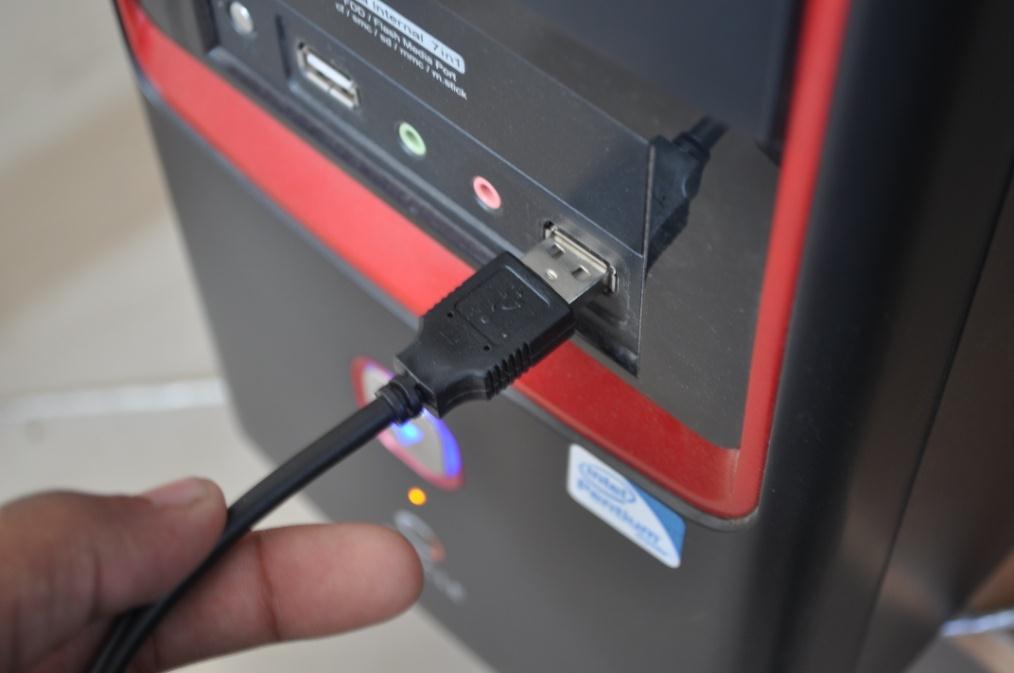
26 STEP 12: Click on Start button in step5-start section. Congratulations on completing your first Microcontroller Program Burning successfully. Note: - AT89Sxx microcontroller can not be programmed using serial port,hence ISP Programmer is used. Installation of Driver STEP 1: Connect the USB cable to the USB 8051 programmer & USB port of the PC or Laptop, the Green LED will glow. You will get the following pop up containing: Found New Hardware USBasp (It means drivers for this hardware is not installed, so we need to install it.) 26
27 27


28 (Note:-If you are getting USB Device Not Recognized then your USB programmer is malfunctioning.) STEP 2: Select Manage by right clicking on My Computer. 28


29 STEP 3: Select Device Manager from System Tools and click on Other devices STEP 3: Select USBasp from Other devices and right click on USBasp and select Update Driver Software 29

30 STEP 4: Click on Browse my computer for driver software. STEP 5: Browse for the driver software in the location you have kept your drivers, and then click on Next. 30


31 STEP 6: Select Install this driver anyway to install the software safely. 31

32 STEP 7: Driver software installation in process. 32


33 STEP 8: Finally the driver will be installing & you will get 33
 LibUSB Win32 Devices ----- USBasp: shows the successfully installation of")
34 STEP 9: Go to the device manager list (Right click on My Computer, Select Manage, You will get the new window named as Computer Management, Select Device Manager present under System Tools) LibUSB Win32 Devices USBasp: shows the successfully installation of driver. 34

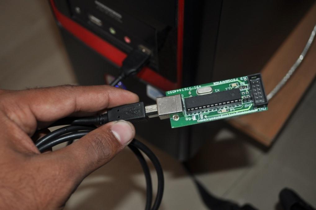
35 Burning the program into microcontroller using progisp: Before you start with burning process get your programmer connected with the development board through an FRC cable connected to ISP port and other end to the programmer board as shown: STEP 1: Open the Progisp software. 35


36 STEP 2: From the Left chip select window select the microcontroller. CLICK Here STEP 3: From the load Flash section browse the.hex file of the project you have built. CLICK Here 36

37 STEP 4: when the program is loaded click on auto button and wait for some time till it finishes programming. Red LED on the programmer board will glow that shows the busy state of the programmer. When it displays the message Erase Write Flash, Verify Flash successfully done your controller is ready to work as per your program, Finally the microcontroller is programmed. 37
38 Troubleshooting: Sr. Problem Causes Remedies No 1. Can t find programmer 1. No connection or loose connection between serial Re-connect the serial cable with the PC. cable and PC. 2. Programmer IC not present or incorrectly placed. Connect the IC properly with correct orientation. 2. Programming failed 1.Microcontroller IC not working properly Replace the microcontroller IC on target Board 2.FRC cable not working Replace the cable connected between target board and programmer 3.Reset failed Press Reset button after pressing Start in Flash Magic 38


39 *Note: For more detail working of module refer datasheet of the ICs. Installation of Driver: STEP 1: Connect the USB cable to the USB AVR programmer & USB port of the PC or Laptop, the Green LED will glow. You will get the following pop up containing: Found New Hardware USBasp it means USB programmer is working. (Note:-If you are getting USB Device Not Recognized then your USB AVR programmer is not working.) STEP 2: Wait for windows information Found New Hardware Wizard. 39


40 STEP 3:After device is detected Driver setup wizard opens. Select where USBASP driver windriver is located in your CD. STEP 4: Wait few seconds with the following window 40


41 STEP 5: Finally the driver will be installing & you will get STEP 6: Go to the device manager list (Right click on My Computer, Select Manage, You will get the new window named as Computer Management, Select Device Manager present under System Tools) 41

42 LibUSB Win32 Devices USBasp :: shows the successfully installation of driver. Contact Address: Campus Component Pvt. Ltd Ackruti Chambers, Office No. 308, 3 rd Floor, Near Laxmi Narayan Theater, Swargate, Pune Mob.: Landline: Address: sales@campuscomponent.com Location Map 42
AVR Development Board
 CAMPUS COMPONENT Pvt. Ltd. 1 DISCLAIMER Information furnished is believed to be accurate and reliable at the time of publication. However, Campus Component Pvt. Ltd. assumes no responsibility arising from
AVR Development Board
 AVR Development Board Campus Component Pvt. Ltd. DISCLAIMER Information furnished is believed to be accurate and reliable at the time of publication. However, Campus Component Pvt. Ltd. assumes no responsibility
FT232 Serial to USB Converter
 FT232 Serial to USB Converter Campus Component Pvt. Ltd. DISCLAIMER Information furnished is believed to be accurate and reliable at the time of publication. However, Campus Component Pvt. Ltd. assumes
RF Transmitter Module
 CAMPUS COMPONENT Pvt. Ltd. 1 DISCLAIMER Information furnished is believed to be accurate and reliable at the time of publication. However, Campus Component Pvt. Ltd. assumes no responsibility arising from
AVR Peripheral Board. Campus Component Pvt. Ltd.
 AVR Peripheral Board Campus Component Pvt. Ltd. DISCLAIMER Information furnished is believed to be accurate and reliable at the time of publication. However, Campus Component Pvt. Ltd. assumes no responsibility
GSM Interfacing Board
 Campus Component Pvt. Ltd. DISCLAIMER Information furnished is believed to be accurate and reliable at the time of publication. However, Campus Component Pvt. Ltd. assumes no responsibility arising from
P89V51RD2 Development Board May 2010
 P89V51RD2 Development Board May 2010 NEX Robotics Pvt. Ltd. 1 P89V51RD2 Development Board Introduction: P89V51RD2 Development Board P89V51RD2 Development Board is a low cost development board which have
SIM28M/28ML GPS Receiver Modem
 CAMPUS COMPONENT Pvt. Ltd. 1 DISCLAIMER Information furnished is believed to be accurate and reliable at the time of publication. However, Campus Component Pvt. Ltd. assumes no responsibility arising from
8051 Intermidiate Development Board. Product Manual. Contents. 1) Overview 2) Features 3) Using the board 4) Troubleshooting and getting help
 Overview 2) Features 3) Using the board 4) Troubleshooting and getting help") 8051 Intermidiate Development Board Product Manual Contents 1) Overview 2) Features 3) Using the board 4) Troubleshooting and getting help 1. Overview 2. Features The board is built on a high quality FR-4(1.6
8051 Intermidiate Development Board Product Manual Contents 1) Overview 2) Features 3) Using the board 4) Troubleshooting and getting help 1. Overview 2. Features The board is built on a high quality FR-4(1.6
AVR-P20 development board Users Manual
 AVR-P20 development board Users Manual All boards produced by Olimex are ROHS compliant Revision A, October 2005 Copyright(c) 2009, OLIMEX Ltd, All rights reserved Page 1 INTRODUCTION: The AVR Microcontrollers
AVR/8051 USB PROGRAMMER
 U s e r M a n u a l f o r A V R / 8 0 5 1 U S B Z I F P r o g r a m m e r P a g e 1 PRODUCT OF It s just an idea until you execute it AVR/8051 USB PROGRAMMER USER MANUAL FOR WINDOWS 8.0 OS U s e r M a
LPC2148 DEV BOARD. User Manual.
 LPC2148 DEV BOARD User Manual www.coineltech.com www.coineltech.com Designed by CoiNel Technology Solutions LLP No-816, 2 nd Floor, 4 th B Cross, 9 th A Main, RPC Layout, Vijaynagar, Bangalore-560040 State:
GIE 8051 Mini Kit. User Manual
 GIE 8051 Mini Kit User Manual www.gie.com.my Page 1 of 8 Content Features...3 Function Block...3 Development Setup...4 Jumper selection...4 Required Software...5 Install PL-2303 Driver (USB to Serial port)...5
AVR-P development board Users Manual
 AVR-P40-8515 development board Users Manual All boards produced by Olimex are ROHS compliant Revision A, January 2002 Copyright(c) 2009, OLIMEX Ltd, All rights reserved Page 1 INTRODUCTION: The AVR Microcontroller
AN10428 UART-SPI Gateway for Philips SPI slave bridges
 UART-SPI Gateway for Philips SPI slave bridges Rev. 01 7 March 2006 Application note Document information Info Keywords Abstract Content UART-SPI Gateway, UART to SPI, RS-232 to SPI The UART-SPI Gateway
8051 Basic Development Board. Product Manual. Contents. 1) Overview 2) Features 3) Using the board 4) Troubleshooting and getting help
 Overview 2) Features 3) Using the board 4) Troubleshooting and getting help") 8051 Basic Development Board Product Manual Contents 1) Overview 2) Features 3) Using the board 4) Troubleshooting and getting help 1. Overview 2. Features The board is built on a high quality FR-4(1.6
8051 Basic Development Board Product Manual Contents 1) Overview 2) Features 3) Using the board 4) Troubleshooting and getting help 1. Overview 2. Features The board is built on a high quality FR-4(1.6
F²MC-8L FAMILY MB89201 SERIES FLASH PROGRAMMING 8-BIT MICROCONTROLLER APPLICATION NOTE. Fujitsu Microelectronics Europe Application Note
 Fujitsu Microelectronics Europe Application Note MCU-AN-300001-E-V10 F²MC-8L FAMILY 8-BIT MICROCONTROLLER MB89201 SERIES FLASH PROGRAMMING APPLICATION NOTE Revision History Revision History Date 2005-02-09
GIE 8051 Professional Kit. User Manual
 GIE 8051 Professional Kit User Manual www.gie.com.my Page 1 of 9 Content Overview...3 Features...3 Function Block...4 Jumper Setting...4 Hardware Connection...5 Required Software...5 Install CH340 Driver
AN10337 Adding ISP firmware to an LPC900 software project
 Rev. 01 13 December 2004 Application note Document information Info Keywords Abstract Content LPC900, ISP This application note describes how to add In-System Programming (ISP) firmware into a Keil µvision
CoiNel Technology Solutions LLP. LPC2148 ARTIST Instruction Manual LPC2148 ARTIST. Instruction manual. Revision 1
 LPC2148 ARTIST Instruction manual Designed by CoiNel Technology Solutions LLP No-816, 2 nd Floor, 4 th B Cross, 9 th A Main, RPC Layout, Vijaynagar, Bangalore-560040 State: Karnataka Country: India www.coineltech.com
Figure 1. Proper Method of Holding the ToolStick. Figure 2. Improper Method of Holding the ToolStick
 TOOLSTICK C8051F560 DAUGHTER CARD USER S GUIDE 1. Handling Recommendations To enable development, the ToolStick Base Adapter and daughter cards are distributed without any protective plastics. To prevent
Programmer. User Guide
 Programmer User Guide Trademarks & Copyright Windows and Windows NT are registered trademarks of Microsoft Corporation. MCS-51 and Pentium are registered trademarks of Intel Corporation. AVR is registered
F2MC MB90385 series Evaluation Board Documentation. Revision Date Comment V New document
 F2MC MB90385 series Evaluation Board Documentation Revision Date Comment V1.0 08.25.02 New document 1 Warranty and Disclaimer To the maximum extent permitted by applicable law, Fujitsu Microelectronics
Manual of Board ET-PIC STAMP 18F8722-K22 ET-PIC STAMP 18F8722-K22
 ET-PIC STAMP 18F8722-K22 ET-PIC STAMP 18F8722-K22 is Board Microcontroller in a series of PIC18F87K22 80-Pin TQFP from Microchip. It designs I/O of MCU on board to interface with CONNECTOR in the format
EPM900 - Overview. Features. Technical Data
 Page 1 of 25 EPM900 - Overview The Keil EPM900 supports in-circuit debugging and parallel Flash ROM programming for the Philips P89LPC9xx device family. EPM900 connects directly to the µvision2 Debugger
F²MC-8FX FAMILY MB951XX SERIES SYNCHRONOUS FLASH PROGRAMMING 8-BIT MICROCONTROLLER APPLICATION NOTE. Fujitsu Microelectronics Europe Application Note
 Fujitsu Microelectronics Europe Application Note MCU-AN-300050-E-V10 F²MC-8FX FAMILY 8-BIT MICROCONTROLLER MB951XX SERIES SYNCHRONOUS FLASH PROGRAMMING APPLICATION NOTE Revision History Revision History
LPC2468 Industrial Reference Design Platform System Development Kit Version 1.2. August 2008
 QuickStart Guide LPC2468 Industrial Reference Design Platform System Development Kit Version 1.2 August 2008 1.0 System Overview The LPC2468 Industrial Reference Design (IRD) is a platform targeted at
Hints and tips when using RC1xx0 RF Modules
 AN001 : HI NTSANDTI PS WHENUSI NGRC1 XX0RFMODULES WeMakeEmbeddedWi r el ess Easyt ouse Hints and tips when using RC1xx0 RF Modules By H.Moholdt Keywords Interfacing to RS232/RS485/RS422 level shifters
Flash Magic Application Note 4 What to do if ISP Does Not Work Embedded Systems Academy 2003, All Rights Reserved
 Flash Magic Application Note 4 What to do if ISP Does Not Work Embedded Systems Academy 2003, All Rights Reserved 1. Introduction This application note describes steps to take and items to check when In-System
RE866 Interface User Guide
 RE866 Interface User Guide 1VV0301387 Rev.0 6/16/2017 [04.2016] Mod. 0809 2016-08 Rev.7 SPECIFICATIONS ARE SUBJECT TO CHANGE WITHOUT NOTICE NOTICE While reasonable efforts have been made to assure the
BV511 Hardware Guide ByVac ByVac Revision 1.0
 BV511 Hardware Guide ByVac ByVac 2007 www.byvac.co.uk Revision 1.0 ByVac 1 Copyright in this work is vested in ByVac and the document is issued in confidence for the purpose only for which it is supplied.
How2Use DT-51 AT89C51XXX BMS. By: IE Team. Picture1 The layout of DT-51 AT89C51XXX BMS
 DT-51 AT89C51XXX BMS Application Note By: IE Team This Application Note (AN) serves as a tutorial of how to use the DT-51 AT89C51XXX Bootloader Micro System along with its supplementary software. The layout
EVB9S08DZ60. Demonstration Board for Freescale MC9S08DZ60. User s Manual
 EVB9S08DZ60 Demonstration Board for Freescale MC9S08DZ60 User s Manual EVB9S08DZ60 Evaluation Board for Freescale MC9S08DZ60 (64-Pin LQFP) User s Manual Revision 1.0 Copyright 2006 SofTec Microsystems
Freeduino USB 1.0. Arduino Compatible Development Board Starter Guide. 1. Overview
 Freeduino USB 1.0 Arduino Compatible Development Board Starter Guide 1. Overview 1 Arduino is an open source embedded development platform consisting of a simple development board based on Atmel s AVR
IMPORTANT NOTICE. As a result, the following changes are applicable to the attached document.
 IMPORTANT NOTICE Dear customer, As from August 2 nd 2008, the wireless operations of NXP have moved to a new company, ST-NXP Wireless. As a result, the following changes are applicable to the attached
AL361A-EVB-A1. Multi-channel Video Processor EVB. Datasheet. (HDMI/AHD-to-HDMI) 2017 by AverLogic Technologies, Corp. Version 1.0
 2017 by AverLogic Technologies, Corp. Version 1.0") AL361A-EVB-A1 Multi-channel Video Processor EVB (HDMI/AHD-to-HDMI) Datasheet Version 1.0 INFORMATION FURNISHED BY AVERLOGIC IS BELIEVED TO BE ACCURATE AND RELIABLE. HOWEVER, NO RESPONSIBILITY IS ASSUMED
AL361A-EVB-A1 Multi-channel Video Processor EVB (HDMI/AHD-to-HDMI) Datasheet Version 1.0 INFORMATION FURNISHED BY AVERLOGIC IS BELIEVED TO BE ACCURATE AND RELIABLE. HOWEVER, NO RESPONSIBILITY IS ASSUMED
Getting Started with MCUXpresso SDK CMSIS Packs
 NXP Semiconductors Document Number: MCUXSDKPACKSGSUG User's Guide Rev. 1, 11/2017 Getting Started with MCUXpresso SDK CMSIS Packs 1 Introduction The MCUXpresso Software Development Kit (SDK) is a comprehensive
LPC1788 Mio Board. User Manual. Revision 1.0 1
 User Manual http://coineltech.com Revision 1.0 1 Designed by CoiNel Technology Solutions LLP No-32, 2 nd Floor, HAPBCO Tower, 9 th Main, RPC Layout, Hampinagar, Bangalore-560040 State: Karnataka Country:
Rhino Robot Control Board [RKI-1550]
![Rhino Robot Control Board [RKI-1550]](/thumbs/75/72064296.jpg "Rhino Robot Control Board [RKI-1550]") Rhino Robot Control Board [RKI-1550] Users Manual Robokits India info@robokits.co.in http://www.robokitsworld.com Page 1 The Rhino Robot control board is versatile and expandable platform for robotics.
Rhino Robot Control Board [RKI-1550] Users Manual Robokits India info@robokits.co.in http://www.robokitsworld.com Page 1 The Rhino Robot control board is versatile and expandable platform for robotics.
swarm kit User Guide Version 1.1
 swarm kit User Guide Version 1.1 Document ID: NA-12-0267-0023-1.1 Document Information Document Information Document Title... Document Version... 1.1 Published... February 27, 2013 (10:00 pm) Current Printing...
F 2 MC-8L FAMILY 8-BIT MICROCONTROLLER MB89201 SERIES GETTING STARTED DEV-MB89N202-APP1 OPERATION MANUAL
 Electronics Source Co., L td. Operation Manual F 2 MC-8L FAMILY 8-BIT MICROCONTROLLER MB89201 SERIES GETTING STARTED DEV-MB89N202-APP1 OPERATION MANUAL Content Introduction 3 1. Chapter 1 Hardware 1.1
USB Debug Adapter. Power USB DEBUG ADAPTER. Silicon Laboratories. Stop. Run. Figure 1. Hardware Setup using a USB Debug Adapter
 C8051F38X DEVELOPMENT KIT USER S GUIDE 1. Kit Contents The C8051F38x Development Kit contains the following items: C8051F380 Target Board C8051Fxxx Development Kit Quick-start Guide Silicon Laboratories
SAB-TFBGAxxx Quick Start Guide. This document applies to SAB-TFBGA100, SAB-TFBGA180, and SAB-TFBGA208.
 This document applies to SAB-TFBGA100, SAB-TFBGA180, and SAB-TFBGA208. THE WILL NOT WORK WITHOUT A USB-ICP PROGRAMMER! Figure 1: SAB-TFGBA180 The is a Socket Adapter Board (SAB) for use with Future Designs
Figure 1. Proper Method of Holding the ToolStick. Figure 2. Improper Method of Holding the ToolStick
 TOOLSTICK C8051F330 DAUGHTER CARD USER S GUIDE 1. Handling Recommendations To enable development, the ToolStick Base Adapter and daughter cards are distributed without any protective plastics. To prevent
USB485 USB to RS485 Converter Card
 USB485 USB to RS485 Converter Card User Manual Version 1.02 RMS Technologies 2533 N. Carson St. #4698, Carson City, NV 89706-0147 1-877-301-3609 www.rmsmotion.com sales@rmsmotion.com Thank you for purchasing
ATMega128 Rapid Robot Controller Board [RKI-1148]
![ATMega128 Rapid Robot Controller Board [RKI-1148]](/thumbs/71/65752688.jpg "ATMega128 Rapid Robot Controller Board [RKI-1148]") ATMega128 Rapid Robot Controller Board [RKI-1148] Users Manual Robokits India info@robokits.co.in Robokits World http://www.robokitsworld.com http://www.robokitsworld.com Page 1 Thank you for purchasing
ATMega128 Rapid Robot Controller Board [RKI-1148] Users Manual Robokits India info@robokits.co.in Robokits World http://www.robokitsworld.com http://www.robokitsworld.com Page 1 Thank you for purchasing
USB Debug Adapter. Power USB DEBUG ADAPTER. Silicon Laboratories. Stop. Run. Figure 1. Hardware Setup Using a USB Debug Adapter
 C8051F33X DEVELOPMENT KIT USER S GUIDE 1. Kit Contents The C8051F33x Development Kit contains the following items: C8051F330 Target Board C8051Fxxx Development Kit Quick-Start Guide AC to DC Power Adapter
USB485. USB to RS485 Converter Card. User Manual for connecting with Windows Vista Version 1.01
 USB485 USB to RS485 Converter Card User Manual for connecting with Windows Vista Version 1.01 RMS Technologies 2533 N. Carson St. #4698, Carson City, NV 89706-0147 1-877- 301-3609 www.rmsmotion.com sales@rmsmotion.com
User Manual. CANopenIA-M0. Starter Kit
 User Manual CANopenIA-M0 Starter Kit Edition 8 March 2017 Page 2 of 21 The information given in this document was compiled and checked carefully. Nevertheless ESS assumes no liability for any mistakes.
USB Debug Adapter. Power USB DEBUG ADAPTER. Silicon Laboratories. Stop. Run. Figure 1. Hardware Setup Using a USB Debug Adapter
 C8051F31X DEVELOPMENT KIT USER S GUIDE 1. Kit Contents The Development Kit contains the following items: C8051F310 Target Board C8051Fxxx Development Kit Quick-Start Guide AC to DC Power Adapter USB Debug
HandsOn Technology -- HT-MC-02 MODEL: HT-MC-02
 HandsOn Technology 8051 μcontroller Starter Kits FLASH μcontroller PROGRAMMER/DEVELOPMENT SYSTEM MODEL: HT-MC-02 8051 is one of the most popular 8-bit µcontroller architectures in use today, learn it the
Copyright mikroelektronika, All rights reserved.
 Copyright mikroelektronika, 22. All rights reserved. TO OUR VALUED CUSTOMERS I want to express my thanks to you for being interested in our products and for having confidence in MikroElektronika. The primary
GTM-204M-4G Industrial 4G LTE Modem User s Manual V1.0 High Quality, Industrial Data Acquisition, and Control Products
 GTM-204M-4G Industrial 4G LTE Modem User s Manual V1.0 High Quality, Industrial Data Acquisition, and Control Products Warranty All products manufactured by ICP DAS are warranted against defective materials
Firmware Upgrading Radiocrafts modules
 AN01 2: FI RMWAREUPGRADI NG RADI OCRAFTSMODULES WeMakeEmbeddedWi r el ess Easyt ouse Firmware Upgrading Radiocrafts modules By T.A.Lunder Introduction The Radiocrafts Demo Boards and USB-sticks include
Figure 1. Proper Method of Holding the ToolStick. Figure 2. Improper Method of Holding the ToolStick
 TOOLSTICK C8051F931 DAUGHTER CARD USER S GUIDE 1. Handling Recommendations To enable development, the ToolStick Base Adapter and daughter cards are distributed without any protective plastics. To prevent
PIC-P28-USB development board Users Manual
 PIC-P28-USB development board Users Manual Rev.A, June 2007 Copyright(c) 2007, OLIMEX Ltd, All rights reserved INTRODUCTION: PIC-P28-USB board was designed in mind to create board which to allow easy interface
Table 1. RS232 Serial Adapter DEBUG Connector Pin Descriptions
 RS232 SERIAL ADAPTER (EC2) USER S GUIDE 1. Contents The RS232 Serial Adapter (EC2) package contains the following items: RS232 Serial Adapter (RS232 to Debug Interface) 7 Ribbon Cable 2. RS232 Serial Adapter
e-link Emulation/Programming Adapter Cable (ESTD-206) User s Guide
 User s Guide") Cable (ESTD-206) User s Guide Revision: V1.00 Date: December 12, 2018 Table of Contents e-link Emulation/Programming Adapter Cable (ESTD-206) Introduction... 3 For the e-link On-Chip Debug Function OCDS...
Cable (ESTD-206) User s Guide Revision: V1.00 Date: December 12, 2018 Table of Contents e-link Emulation/Programming Adapter Cable (ESTD-206) Introduction... 3 For the e-link On-Chip Debug Function OCDS...
AN Interfacing Philips Bridge IC with Philips microcontroller. Document information
 AN0 Rev. 0 May 00 Application note Document information Info Keywords Abstract Content SCIS0 to PLPC, Bridge IC to microcontroller, serial interface The operation and description of Philips LPC00 Series
QUASAR PROJECT KIT # ATMEL AVR PROGRAMMER
 This kit is a simple but powerful programmer for the Atmel AT90Sxxxx ( AVR ) family of microcontrollers. The Atmel AVR devices are a low-power CMOS 8-bit microcontroller using a RISC architecture. By executing
CMSIS DAP Setup. Document Version History Document Version ngxtechnologies.com 2
 Document Version History Document Version - 1.0 Author Vinayak ngxtechnologies.com 2 Table of Contents INTRODUCTION...4 REQUIREMENTS...4 HARDWARE...4 SOFTWARE...4 SETUP...4 DISCLAIMERS...8 ngxtechnologies.com
MegaAVR-DEVelopment Board Progressive Resources LLC 4105 Vincennes Road Indianapolis, IN (317) (317) FAX
 (317) FAX") MegaAVR-DEVelopment Board Progressive Resources LLC 4105 Vincennes Road Indianapolis, IN 46268 (317) 471-1577 (317) 471-1580 FAX http://www.prllc.com GENERAL The MegaAVR-Development board is designed for
MegaAVR-DEVelopment Board Progressive Resources LLC 4105 Vincennes Road Indianapolis, IN 46268 (317) 471-1577 (317) 471-1580 FAX http://www.prllc.com GENERAL The MegaAVR-Development board is designed for
Quick-Start Guide. BNS Solutions. QSK62P Plus
 BNS Solutions Quick-Start Guide QSK62P Plus RS-232 Port Link LED 8-character x 2-line LCD Expansion Port (2) Reset Switch Power LED Thermistor I/O Ring (4) M16C MCU Analog Adjust Pot MCU Crystal Expansion
USER GUIDE. Atmel Segment LCD1 Xplained Pro. Preface
 USER GUIDE Atmel Segment LCD1 Xplained Pro Preface Atmel Segment LCD1 Xplained Pro is an extension board to the Atmel Xplained Pro evaluation platform. Segment LCD1 Xplained Pro is designed to kick-start
AL362B-EVB-A1. AHD-to-HDMI Quad Box Development Kit by AverLogic Technologies, Corp. Version 1.0
 AL362B-EVB-A1 AHD-to-HDMI Quad Box Development Kit Version 1.0 INFORMATION FURNISHED BY AVERLOGIC IS BELIEVED TO BE ACCURATE AND RELIABLE. HOWEVER, NO RESPONSIBILITY IS ASSUMED BY AVERLOGIC FOR ITS USE,
USB Debug Adapter. Power USB DEBUG ADAPTER. Silicon Laboratories. Stop. Run. Figure 1. Hardware Setup Using a USB Debug Adapter
 C8051F32X DEVELOPMENT KIT USER S GUIDE 1. Kit Contents The C8051F32x Development Kit contains the following items: C8051F320 Target Board C8051Fxxx Development Kit Quick-Start Guide AC to DC Power Adapter
EVB-USB2514Q48 48-Pin QFN Evaluation Board Revision A1
 EVB-USB2514Q48 48-Pin QFN Evaluation Board Revision A1 Copyright 2007 SMSC or its subsidiaries. All rights reserved. The information contained herein is proprietary to SMSC and shall be used solely in
UPort 2000 Series User s Manual
 User s Manual Second Edition, December 2012 www.moxa.com/product 2012 Moxa Inc. All rights reserved. User s Manual The software described in this manual is furnished under a license agreement and may be
I-7560U/7561U/7563U. User Manual WARRANTY WARNING COPYRIGHT TRADEMARKS CONTACT US
 I-7560U/7561U/7563U User Manual USB tto RS--232//422//485 Converrtterrss Verr.. 1..0,, Decc.. 2013 WARRANTY All products manufactured by ICP DAS are warranted against defective materials for a period of
Easy Kit Board Manual
 User s Manual, V1.0, June2008 Easy Kit Board Manual Easy Kit - XC88x Microcontrollers Edition 2008-06 Published by Infineon Technologies AG, 81726 München, Germany Infineon Technologies AG 2008. All Rights
EMULATOR SYSTEM MB
 Fujitsu Microelectronics Europe Application Note MCU-AN-391026-E-V12 FR FAMILY SUPPORT TOOL EMULATOR SYSTEM MB2198-01 INSTALLATION GUIDE MB2198-01 APPLICATION NOTE Revision History Revision History Date
EKK-LM3S811 QUICKSTART
 Stellaris LM3S811 Evaluation Kit The Stellaris LM3S811 Evaluation Kit provides a low-cost way to start designing with Stellaris microcontrollers. The LM3S811 Evaluation Board (EVB) can function as either
Preliminary. PACKAGE - 28-pin MLP (5mm X 5mm) Example Circuit Diagram CP V. 48MHz Oscillator. USB Function Controller 512B EEPROM
 Example Circuit Diagram CP V. 48MHz Oscillator. USB Function Controller 512B EEPROM") Preliminary Single-Chip USB to UART Bridge SINGLE-CHIP USB to UART DATA TRANSFER - Integrated USB Transceiver; No External Resistors Required - Integrated Clock; No External Crystal Required - Integrated
Preliminary Single-Chip USB to UART Bridge SINGLE-CHIP USB to UART DATA TRANSFER - Integrated USB Transceiver; No External Resistors Required - Integrated Clock; No External Crystal Required - Integrated
Megawin 8051 ISP via COM Port
 Megawin 8051 ISP via COM Port User Manual By Vincent Y. C. Yu This document information is the intellectual property of Megawin Technology Co., Ltd. 1 Contents 1 What is ISP... 3 2 Chip Configuration for
UM QN908x Quick Start. Document information. QN908x, Quick Start, Development Kit, QN9080 DK, QN9080 Development Kit
 QN908x Quick Start Rev.2.0 21 March 2018 User manual Document information Info Keywords Abstract Content QN908x, Quick Start, Development Kit, QN9080 DK, QN9080 Development Kit This Quick Start document
UM PCAL6524 demonstration board OM Document information
 Rev. 1 23 September 2015 User manual Document information Info Content Keywords OM13320 Fm+ development kit, OM13260 Fm+ I2C bus development board, OM13303 GPIO target board Abstract Installation guide
QT3 Xplained Pro. Preface. Atmel QTouch USER GUIDE
 Atmel QTouch QT3 Xplained Pro USER GUIDE Preface The Atmel QT3 Xplained Pro is an extension board, which enables the evaluation of a capacitive touch 12 key numpad in mutual capacitance configuration.
AC/DC. Adapter. Ribbon. Cable Serial. Serial. Adapter. Figure 1. Hardware Setup using an EC2 Serial Adapter
 C8051F32X DEVELOPMENT KIT USER S GUIDE 1. Kit Contents The C8051F32x Development Kit contains the following items: C8051F320 Target Board C8051Fxxx Development Kit Quick-Start Guide C8051F32x Development
AVR 40 Pin Rapid Robot controller board
 AVR 40 Pin Rapid Robot controller board User Manual Robokits India http://www.robokits.org info@robokits.org - 1 - Thank you for purchasing the AVR 40 Pin Rapid Robot controller board. This unit has been
C8051F700-DK C8051F700 DEVELOPMENT KIT USER S GUIDE. 1. Relevant Devices. 2. Kit Contents. 3. Hardware Setup
 C8051F700 DEVELOPMENT KIT USER S GUIDE 1. Relevant Devices The C8051F700 Development Kit is intended as a development platform for the microcontrollers in the C8051F70x/71x MCU family. The members of this
USB Debug Adapter. Power USB DEBUG ADAPTER. Silicon Laboratories. Stop. Run. Figure 1. Hardware Setup Using a USB Debug Adapter
 C8051F34X DEVELOPMENT KIT USER S GUIDE 1. Kit Contents The C8051F34x Development Kit contains the following items: C8051F340 Target Board C8051Fxxx Development Kit Quick-Start Guide AC to DC Power Adapter
CYClockMaker Programming Kit Guide CY3675. Doc. # Rev. **
 CY3675 CYClockMaker Programming Kit Guide Doc. # 001-52414 Rev. ** Cypress Semiconductor 198 Champion Court San Jose, CA 95134-1709 Phone (USA): 800.858.1810 Phone (Intnl): 408.943.2600 http://www.cypress.com
AVR Intermediate Development Board. Product Manual. Contents. 1) Overview 2) Features 3) Using the board 4) Troubleshooting and getting help
 Overview 2) Features 3) Using the board 4) Troubleshooting and getting help") AVR Intermediate Development Board Product Manual Contents 1) Overview 2) Features 3) Using the board 4) Troubleshooting and getting help 1. Overview 2. Features The board is built on a high quality FR-4(1.6
AVR Intermediate Development Board Product Manual Contents 1) Overview 2) Features 3) Using the board 4) Troubleshooting and getting help 1. Overview 2. Features The board is built on a high quality FR-4(1.6
Relay Board. User Manual. 1.0, Oct 2013
 Relay Board User Manual 1.0, Oct 2013 This work is licensed under the Creative Commons Attribution-Share Alike 2.5 India License. To view a copy of this license, visit http://creativecommons.org/licenses/by-sa/2.5/in/
USB Debug Adapter. Power USB DEBUG ADAPTER. Silicon Laboratories. Stop. Run. Figure 1. Hardware Setup using a USB Debug Adapter
 C8051F2XX DEVELOPMENT KIT USER S GUIDE 1. Kit Contents The C8051F2xx Development Kits contain the following items: C8051F206 or C8051F226 Target Board C8051Fxxx Development Kit Quick-Start Guide Silicon
Atmel AVR datasheet. Matrix Multimedia Atmel AVR Board EB Contents
 Atmel AVR datasheet Contents 1. About this document 2. General information 3. Board overview 4. Getting Started 5. Block schematic and description Appendix A. Circuit diagram B. Compatible AVR device C.
Copyright mikroelektronika, January All rights reserved.
 Copyright mikroelektronika, January 22. All rights reserved. TO OUR VALUED CUSTOMERS I want to express my thanks to you for being interested in our products and for having confidence in MikroElektronika.
M32 Development Board
 M32 Development Board User Guide Document Control Information This Document Release Date: 12th March 2006 This Document Version: 1.0 Document History Author Release Date Reference Release Notes JSL 23rd
ToolStick-EK TOOLSTICK USER S GUIDE. 1. Kit Contents. 2. ToolStick Overview. Green and Red LEDs. C8051F321 provides USB debug interface.
 TOOLSTICK USER S GUIDE 1. Kit Contents The ToolStick kit contains the following items: ToolStick Silicon Laboratories Evaluation Kit IDE and Product Information CD-ROM. CD content includes: Silicon Laboratories
Breeze Board. Type A. User Manual.
 Breeze Board Type A User Manual www.dizzy.co.za Contents Introduction... 3 Overview Top... 4 Overview Bottom... 5 Getting Started (Amicus Compiler)... 6 Power Circuitry... 7 USB... 8 Microcontroller...
BlueEva+S42M Evaluation Kit User Guide. 1VV Rev
 BlueEva+S42M Evaluation Kit User Guide 1VV0301390 Rev. 1 2018-01-15 SPECIFICATIONS ARE SUBJECT TO CHANGE WITHOUT NOTICE NOTICE While reasonable efforts have been made to assure the accuracy of this document,
PIC-P40 development board Users Manual
 PIC-P40 development board Users Manual All boards produced by Olimex are ROHS compliant Rev.E, February 008 Copyright(c) 008, OLIMEX Ltd, All rights reserved Page INTRODUCTION: PIC-P40 board is development
EZ-USB FX3 Development Kit Guide
 CYUSB3KIT-001 EZ-USB FX3 Development Kit Guide Doc. #: 001-70237 Rev. *A Cypress Semiconductor 198 Champion Court San Jose, CA 95134-1709 Phone (USA): 800.858.1810 Phone (Intnl): 408.943.2600 http://www.cypress.com
ET-AVRProg mini. Technical Specifications of ET-AVRProg mini
 ET-AVRProg mini ET-AVRProg mini is the board that is designed to download HEX File into AVR Microcontroller of ATMEL through PORT ISP. It is compatible with Program AvrProg, AvrOspll, CodeVision, avrdude
ET-BASE AVR (ATmega8535)
") ET-BASE AVR (ATmega8535) ET-BASE AVR which is AVR Board Microcontroller from ATMEL has MCU No. Atmega8535 40 Pin in circuit. Board ET-BASE AVR uses MCU resources as main and I/O PORT are arranged as PORT
ET-BASE AVR (ATmega8535) ET-BASE AVR which is AVR Board Microcontroller from ATMEL has MCU No. Atmega8535 40 Pin in circuit. Board ET-BASE AVR uses MCU resources as main and I/O PORT are arranged as PORT
Figure 1. CP2108 USB-to-Quad UART Bridge Controller Evaluation Board
 CP2108 EVALUATION KIT USER S GUIDE 1. Introduction The CP2108 is a highly integrated USB-to-Quad-UART Bridge Controller providing a simple solution for updating RS-232/RS-485 designs to USB using a minimum
AN LPC1700 secondary USB bootloader. Document information. LPC1700, Secondary USB Bootloader, ISP, IAP
 LPC1700 secondary USB bootloader Rev. 01 8 September 2009 Application note Document information Info Keywords Abstract Content LPC1700, Secondary USB Bootloader, ISP, IAP This application note describes
ICP05 IBOARD LITE ICP05. - iboard lite
 ICP05 - iboard lite 1. Introduction and overview icp05 offers unprecedented level of performance, reliability and scalability for Microchip PIC IO Kit solution. By the same time, it allows users to program
Figure 1. Proper Method of Holding the ToolStick. Figure 2. Improper Method of Holding the ToolStick
 TOOLSTICK UNIVERSITY DAUGHTER CARD USER S GUIDE 1. Handling Recommendations To enable development, the ToolStick Base Adapter and daughter cards are distributed without any protective plastics. To prevent
Keil TM MDK-ARM Quick Start for. Holtek s HT32 Series Microcontrollers
 Keil TM MDK-ARM Quick Start for Holtek s Microcontrollers Revision: V1.10 Date: August 25, 2011 Table of Contents 1 Introduction... 5 About the Quick Start Guide... 5 About the Keil MDK-ARM... 6 2 System