SIM28M/28ML GPS Receiver Modem
|
|
|
- Arleen Carter
- 5 years ago
- Views:
Transcription


1 CAMPUS COMPONENT Pvt. Ltd. 1
2 DISCLAIMER Information furnished is believed to be accurate and reliable at the time of publication. However, Campus Component Pvt. Ltd. assumes no responsibility arising from the use of the specifications described. The applications mentioned herein are used solely for the purpose of illustration and Campus component Pvt. Ltd. makes no warranty or representation that such applications will be suitable without further modification, nor recommends the use of its products for application that may present a risk to human life due to malfunction or otherwise. Campus Component Pvt. Ltd. does not assume any liability arising out of the application or use of any product or circuit described herein; neither does it convey any license under its patents rights, nor the rights of other. Campus Component Pvt. Ltd. reserves the right to alter its products without prior notification. For the most up-to-date information, please visit our web site at Copyright 2014 CAMPUS COMPONENT Pvt. Ltd. All rights reserved. Campus Component Pvt. Ltd., logo and combinations thereof, are registered trademarks of CAMPUS COMPONENT Pvt. Ltd. Other terms and product names may be trademarks of others. Page 2

3 GPS Receiver Modem This GPS Receiver Modem is based on SIMCOM s SIM28M/SIM28ML GPS Module. SIM28M is a stand-alone or A-GPS receiver. With built in LNA, SIM28M can relax antenna requirement and don t need for external LNA. SIM28M can track as low as -165dBm signal even without network assistance. SIM28M has excellent low power consumption characteristics (acquisition 17mA, tracking 16mA). SIM28M supports various location and navigation applications, including autonomous GPS, QZSS, SBAS ranging (WASS, EGNOS, GAGAN, MSAS), DGPS and A-GPS. Hardware Description: Page 3
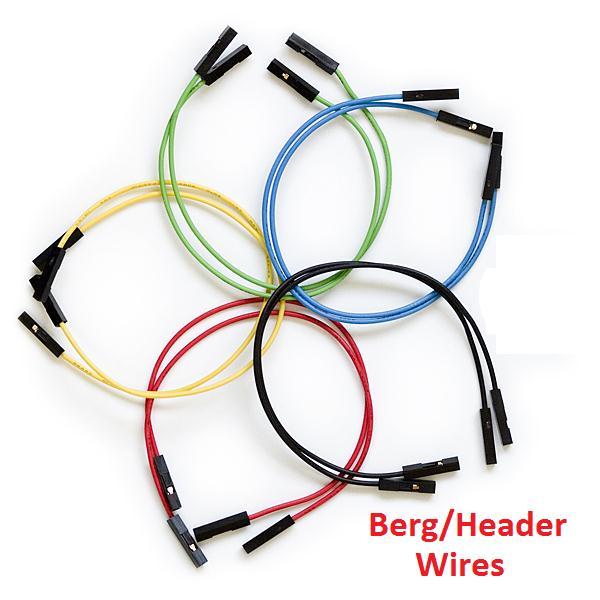
4 A 9~15V DC (DC Only) Adaptor can be used to power up this modem. Adaptor can be connected to DC Jack/Socket J1. User can also share power supply available on their other circuit boards using berg/header wires. 9V~15V DC can be connected to Vin (Input Voltage) and GND (Ground/0V) Pins at male header JP1. A diode (D1) protects the modem from reverse polarity. User can also power up this modem by sharing voltage level +5V or +3.3V from their other circuit boards. +5V or +3.3V must be connected at JP1. (Caution: Reverse Polarity Protection (RPP) is only available to Vin & GND Pins, any wrong connection to +5V/GND or +3.3V/GND or +5V/3.3V pins may damage modem permanently, so utmost care should be taken while providing power from these pins) SIM28M IC runs on +3.3V supply, 9~15V is given to the input of LM7805 voltage regulator IC. LM7805 IC gives a output of +5V which is provided as input to LM1117 IC which gives +3.3V output to SIM28M IC. So user should share only one voltage level (There are three voltage levels on GPS Receiver Modem Board:- Vin, +5V & +3.3V) GND being common is ignored. 1. Providing supply at Vin Pin or DC Jack J1 (9V~15V DC) will automatically generate +5V & +3.3V from voltage regulators on GPS Receiver Modem Board. 2. Providing a +5V supply at +5V pin of JP1 will automatically generate +3.3V from voltage regulator LM1117 (IC1) on GPS Receiver Modem Board. Please Note:- +5V in this case is generated by voltage regulator on your other circuit board, not the one on GPS modem. Actually we are bypassing modem s +5V regulator. 3. Providing a +3.3V supply at +3.3V pin of JP1 will power up SIM28M IC. Please Note:- +3.3V in this case is generated by voltage regulator on your other circuit board, not the one on GPS modem. Actually in this case we are bypassing modem s both +5V & +3.3V regulators. For powering up GPS Board give supply from:- (J1 alone or Vin alone or +5V alone or +3.3V alone & ofcourse GND will be used in each combination.) PWR LED:- Power LED ON indicates board is powered up. Page 4
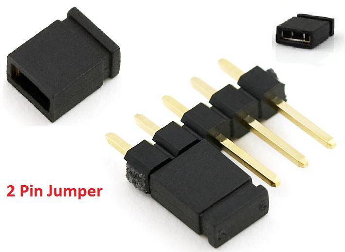
5 TMRK LED:- Timemark LED is connected to TIMEMARK pin which starts blinking at 1Hz (1PPS one pulse per second) when GPS is FIXED. RS232 Interface:- Any RS232 compatible device like PC can be connected to DB9 connector J2. User can observe data flow on softwares like hyperterminal, realterm etc. Baudrate to select is TTL Interface:- User can directly use TTL output which is available at connector JP2. A level shifter is used to make it compatible with +5V & +3.3V microcontrollers. A 2 pin jumper is in default connection with BFR & +5V pins of JP2 so TTL RX/TX of GPS modem can be connected to RX/TX of any +5V microcontroller like 8051, AVR, PIC etc.. For any +3.3V microcontroller like LPC2138, LPC2148, Cortex-M3 etc. connect the jumper BFR & +3.3V Pins. Jumper position at:- 1. BFR & +5V:- TTL RX/TX of GPS modem can be connected to RX/TX of any +5V microcontroller like 8051, AVR, PIC etc. 2. BFR & +3.3V:- TTL RX/TX of GPS modem can be connected to RX/TX of any +3.3V microcontroller like LPC2138, LPC2148, Cortex-M3 etc. Page 5
6 Circuit Diagram:- Page 6
7 Page 7
GSM Interfacing Board
 Campus Component Pvt. Ltd. DISCLAIMER Information furnished is believed to be accurate and reliable at the time of publication. However, Campus Component Pvt. Ltd. assumes no responsibility arising from
FT232 Serial to USB Converter
 FT232 Serial to USB Converter Campus Component Pvt. Ltd. DISCLAIMER Information furnished is believed to be accurate and reliable at the time of publication. However, Campus Component Pvt. Ltd. assumes
AVR Development Board
 AVR Development Board Campus Component Pvt. Ltd. DISCLAIMER Information furnished is believed to be accurate and reliable at the time of publication. However, Campus Component Pvt. Ltd. assumes no responsibility
AVR Development Board
 CAMPUS COMPONENT Pvt. Ltd. 1 DISCLAIMER Information furnished is believed to be accurate and reliable at the time of publication. However, Campus Component Pvt. Ltd. assumes no responsibility arising from
RF Transmitter Module
 CAMPUS COMPONENT Pvt. Ltd. 1 DISCLAIMER Information furnished is believed to be accurate and reliable at the time of publication. However, Campus Component Pvt. Ltd. assumes no responsibility arising from
8051 General Purpose Board
 8051 General Purpose Board CAMPUS COMPONENT Pvt. Ltd. www.campuscomponent.com 1 DISCLAIMER Information furnished is believed to be accurate and reliable at the time of publication. However, Campus Component
AVR Peripheral Board. Campus Component Pvt. Ltd.
 AVR Peripheral Board Campus Component Pvt. Ltd. DISCLAIMER Information furnished is believed to be accurate and reliable at the time of publication. However, Campus Component Pvt. Ltd. assumes no responsibility
AN10428 UART-SPI Gateway for Philips SPI slave bridges
 UART-SPI Gateway for Philips SPI slave bridges Rev. 01 7 March 2006 Application note Document information Info Keywords Abstract Content UART-SPI Gateway, UART to SPI, RS-232 to SPI The UART-SPI Gateway
Cytron USB to UART Converter UC00A
 Cytron USB to UART Converter UC00A User s Manual V1.1 August 2009 Information contained in this publication regarding device applications and the like is intended through suggestion only and may be superseded
BLE232: Manual Copyright 2014 taskit GmbH
 BLE232 Manual BLE232: Manual Copyright 2014 taskit GmbH BLE232 All rights to this documentation and to the product(s) described herein are reserved by taskit GmbH. This document was written with care,
VENUS_ Driving Board and 39.6 Prism Display
 VENUS_ Driving Board and 39.6 Prism Display Table of Contents 1 Hardware Requirements... 1 (1) PACKAGE CONTENTS... 1 (2) VENUS Specification... 2 (3) Prism product Specification... 3 2 Hardware Guide...
AVR-P20 development board Users Manual
 AVR-P20 development board Users Manual All boards produced by Olimex are ROHS compliant Revision A, October 2005 Copyright(c) 2009, OLIMEX Ltd, All rights reserved Page 1 INTRODUCTION: The AVR Microcontrollers
e-link Emulation/Programming Adapter Cable (ESTD-206) User s Guide
 User s Guide") Cable (ESTD-206) User s Guide Revision: V1.00 Date: December 12, 2018 Table of Contents e-link Emulation/Programming Adapter Cable (ESTD-206) Introduction... 3 For the e-link On-Chip Debug Function OCDS...
Cable (ESTD-206) User s Guide Revision: V1.00 Date: December 12, 2018 Table of Contents e-link Emulation/Programming Adapter Cable (ESTD-206) Introduction... 3 For the e-link On-Chip Debug Function OCDS...
PIC-P40 development board Users Manual
 PIC-P40 development board Users Manual All boards produced by Olimex are ROHS compliant Rev.E, February 008 Copyright(c) 008, OLIMEX Ltd, All rights reserved Page INTRODUCTION: PIC-P40 board is development
Table 1. RS232 Serial Adapter DEBUG Connector Pin Descriptions
 RS232 SERIAL ADAPTER (EC2) USER S GUIDE 1. Contents The RS232 Serial Adapter (EC2) package contains the following items: RS232 Serial Adapter (RS232 to Debug Interface) 7 Ribbon Cable 2. RS232 Serial Adapter
USER S MANUAL. C4 SAFETY CHARGE PUMP BOARD Rev. 6.2
 USER S MANUAL C4 SAFETY CHARGE PUMP BOARD Rev. 6.2 March 2013 USER'S MANUAL TABLE OF CONTENTS Page # Contents 1.0 OVERVIEW... 1 2.0 FEATURES... 1 3.0 SPECIFICATIONS... 2 4.0 SIMPLIFIED SCHEMAT... 2 5.0
Moxa TCC-100 Series Hardware Installation Guide
 Moxa TCC-100 Series Hardware Installation Guide Twelfth Edition, January 2015 www.moxa.com/product 2015 Moxa Inc. All rights reserved. P/N: 1802001000319 Moxa TCC-100 Series Hardware Installation Guide
AN231K04-DVLP3 AnadigmApex Development Board
 1.0 Overview The AnadigmApex development board is an easy-to-use platform designed to help you get started with implementing and testing your analog designs on the AnadigmApex FPAA silicon devices. While
AVR Intermediate Development Board. Product Manual. Contents. 1) Overview 2) Features 3) Using the board 4) Troubleshooting and getting help
 Overview 2) Features 3) Using the board 4) Troubleshooting and getting help") AVR Intermediate Development Board Product Manual Contents 1) Overview 2) Features 3) Using the board 4) Troubleshooting and getting help 1. Overview 2. Features The board is built on a high quality FR-4(1.6
AVR Intermediate Development Board Product Manual Contents 1) Overview 2) Features 3) Using the board 4) Troubleshooting and getting help 1. Overview 2. Features The board is built on a high quality FR-4(1.6
AVR-P development board Users Manual
 AVR-P40-8515 development board Users Manual All boards produced by Olimex are ROHS compliant Revision A, January 2002 Copyright(c) 2009, OLIMEX Ltd, All rights reserved Page 1 INTRODUCTION: The AVR Microcontroller
ACLD Channel Opto-isolated Digital Input Board
 ACLD-9182 16 Channel Opto-isolated Digital Input Board @ Copyright 1996 All Rights Reserved. Manual edition 01, January 1996 The information in this document is subject to change without prior notice in
E IO-Link Transceiver Evaluation Kit PCB 2 (with external transistor)
") E981.10 IO-Link evaluation Kit PCB 2 (with external transistor) AN 006 E981.10 IO-Link Transceiver Evaluation Kit PCB 2 (with external transistor) 1 What you get - E981.10 IO-Link Evaluation Kit PCB 2
E981.10 IO-Link evaluation Kit PCB 2 (with external transistor) AN 006 E981.10 IO-Link Transceiver Evaluation Kit PCB 2 (with external transistor) 1 What you get - E981.10 IO-Link Evaluation Kit PCB 2
CDB4350 Evaluation Board for CS4350
 Evaluation Board for CS4350 Features Description No High Frequency Master Clock Required Stand-Alone or PC GUI Board Control CS8416 Receives S/PDIF-Compatible Digital Audio Headers for External PCM Audio
SER-4485-SI-M USER S MANUAL
 SER-4485-SI-M USER S MANUAL 2017 May Edition Titan Electronics Inc. Web: www.titan.tw The computer programs provided with the hardware are supplied under a license. The software provided should be used
ZLED7030KIT-D1 Demo Kit Description
 ZLED7030KIT-D Demo Kit Description Kit Important Notice Restrictions in Use IDT s ZLED7030KIT-D Demo Kit hardware is designed for ZLED7030 demonstration, evaluation, laboratory setup, and module development
Datasheet BT85x Series Development Kits
 A BT85x Series Development Kits Applicable to the following Laird part numbers: DVK-BT850-SA DVK-BT850-ST Version 1.0 REVISION HISTORY Version Date Notes Contributor Approver 1.0 12 Jan 2018 Initial Release
AL5812EV3 User Guide 150mA, 60V Low-side Adjustable Linear LED Driver
 General Description The AL5812 is an adjustable Linear LED driver offering excellent temperature stability and output handling capability. The AL5812 simplifies the design of linear and isolated or non-isolated
M68HC705E24PGMR PROGRAMMER USER'S MANUAL
 M68HC705E24PGMR/D Rev. 2 March 1995 M68HC705E24PGMR PROGRAMMER USER'S MANUAL Third Edition MOTOROLA Ltd., 1993, 1995; All Rights Reserved Motorola reserves the right to make changes without further notice
RN-174 WiFly Super Module
 RN- WiFly Super Module Features Evaluation board for the RN- module Supports chip antenna (RN--C), PCB trace antenna (RN--P), wire antenna (RN--W), and U.FL connector for an external antenna (RN--U) Ultra-low
Freedom FRDM-MC-LVBLDC Development Platform User s Guide
 Freescale Semiconductor, Inc. Document Number: FRDMLVBLDCUG User's Guide 0, 02/2016 Freedom FRDM-MC-LVBLDC Development Platform User s Guide 1. Introduction The Freedom development platform is a set of
MOD-RFID125 User Manual. All boards produced by Olimex are ROHS compliant. Rev.A, February 2008 Copyright(c) 2008, OLIMEX Ltd, All rights reserved
 2008, OLIMEX Ltd, All rights reserved") MOD-RFID125 User Manual All boards produced by Olimex are ROHS compliant Rev.A, February 2008 Copyright(c) 2008, OLIMEX Ltd, All rights reserved INTRODUCTION: FEATURES: MOD-RFID125 is an RFID station,
MOD-RFID125 User Manual All boards produced by Olimex are ROHS compliant Rev.A, February 2008 Copyright(c) 2008, OLIMEX Ltd, All rights reserved INTRODUCTION: FEATURES: MOD-RFID125 is an RFID station,
MOD-RFID125-BOX User Manual
 MOD-RFID125-BOX User Manual All boards produced by Olimex are ROHS compliant Rev.B, May 2011 Copyright(c) 2011, OLIMEX Ltd, All rights reserved Page 1 INTRODUCTION: FEATURES: MOD-RFID125-BOX is an RFID
1 General Description
 AS5030 AS5011 8 Low BIT PROGRAMMABLE power Integrated Hall HIGH IC SPEED for MAGNETIC human interface ROTARY applications ENCODER DEMOBOARD DEMOBOARD OPERATION AND MANUAL SOFTWARE OPERATION MANUAL 1 General
2001 Mixed-Signal Products SLOU091A
 User s Guide 2001 Mixed-Signal Products SLOU091A Preface How to Use This Manual This document contains the following chapters: Chapter 1 Introduction Chapter 2 Operation Related Documentation From Texas
AQ_G24 GSM Terminal Card Motorola Cellular GSM Engine
 AQ_G24 GSM Terminal Card Motorola Cellular GSM Engine Version: 01.01 AQ_G24 Terminal Card_HD_V01.01 17.JUL.2008-1 - Hardware Interface Description 1. Hardware Features of the AQ_G24 Terminal Card Feature
Octagon Systems Corporation, the Octagon logo, the Micro PC log and Micro PC are trademarks of Octagon Systems Corporation.
 5974 PC 104 Card COPYRIGHT Copyright 1993 Octagon Systems Corporation. All rights reserved. However, any part of this document may be reproduced provided that Octagon Systems Corporation is cited as the
ATA2000-PSU PC/104-Plus Power Supply and Storage Controller
 ATA2000-PSU PC/104-Plus Power Supply and Storage Controller Document version: A.01 HARDWARE REFERENCE MANUAL Definitions AMP and Advanced Micro Peripherals are the trading names for Advanced Micro Peripherals
µ-blox GPS-PS1 GPS Receiver Board based on SiRFstar I/LX TM -Datasheet-
 µ-blox GPS-PS1 GPS Receiver Board based on SiRFstar I/LX TM -Datasheet- June 29, 1999 µ-blox ag Gloriastrasse 35 CH-8092 Zürich Switzerland http://www.u-blox.ch 1 Features ƒ Full Implementation of the
HYDRA-X10. Power Application Controllers TM. PAC HYDRA-X User s Guide. Copyright 2014 Active-Semi, Inc.
 HYDRA-X10 Power Application Controllers TM PAC5210 - HYDRA-X User s Guide www.active-semi.com Copyright 2014 Active-Semi, Inc. CONTENTS Contents...2 Overview...3 HYDRA-X10 Body Resources...5 Header Descriptions...5
XEELAS NODE MANUAL X-COM VERSION 1.0
 This document is the official manual for the Xeelas LoRa Node. In this document, all the functions and technical specifications are described. X-COM VERSION 1.0 XEELAS NODE MANUAL Manual for Software version
AN231K04-DVLP3 AnadigmApex Development Board
 1.0 Overview The AnadigmApex development board is an easy-to-use platform designed to help you get started with implementing and testing your analog designs on the AnadigmApex FPAA silicon devices. While
ICP05 IBOARD LITE ICP05. - iboard lite
 ICP05 - iboard lite 1. Introduction and overview icp05 offers unprecedented level of performance, reliability and scalability for Microchip PIC IO Kit solution. By the same time, it allows users to program
Datasheet BT860 Development Kit
 A BT860 Development Kit Applicable to the following Laird part numbers: - DVK-BT860-SA Integrated antenna version - DVK-BT860-ST Trace pin for external antenna version Version 1.0 REVISION HISTORY Version
UM0401 User manual. User manual for eight bit port expander STMPE801 demonstration board. Introduction
 User manual User manual for eight bit port expander STMPE801 demonstration board Introduction This document explains the functioning of the demo board for the port expander Chip STMPE801 with a PC GUI
EVAL6235PD. L6235 three-phase brushless DC motor driver demonstration board. Features. Description
 L6235 three-phase brushless DC motor driver demonstration board Features Operating supply voltage from 8 V to 52 V 5.6 A output peak current (2.8 A RMS ) Operating frequency up to 100 khz Non-dissipative
I-7560U/7561U/7563U. User Manual WARRANTY WARNING COPYRIGHT TRADEMARKS CONTACT US
 I-7560U/7561U/7563U User Manual USB tto RS--232//422//485 Converrtterrss Verr.. 1..0,, Decc.. 2013 WARRANTY All products manufactured by ICP DAS are warranted against defective materials for a period of
AN2470 Application note TS4871 low voltage audio power amplifier Evaluation board user guidelines Features Description
 Application note TS4871 low voltage audio power amplifier Evaluation board user guidelines Features TS4871 low voltage audio power amplifier with active low standby mode Operating range from V CC =2.2V
M68HC705E6PGMR PROGRAMMER USER'S MANUAL
 M68HC705E6PGMR/D2 nc. Oct 1993 M68HC705E6PGMR PROGRAMMER USER'S MANUAL Motorola reserves the right to make changes without further notice to any products herein to improve reliability, function or design.
PP-BOB2-V1.0 PARALLEL PORT BREAKOUT BOARD
 PP-BOB2-v1 PARALLEL PORT BREAKOUT BOARD Document: Operation Manual Document #: T17 Document Rev: 2.0 Product: PP-BOB2-v1.0 Product Rev: 1.0 Created: March, 2013 Updated: Dec, 2014 THIS MANUAL CONTAINS
HYDRA-X23/X23S. Power Application Controllers. PAC HYDRA-X User s Guide. Copyright 2014 Active-Semi, Inc.
 HYDRA-X23/X23S Power Application Controllers PAC5223 - HYDRA-X User s Guide www.active-semi.com Copyright 2014 Active-Semi, Inc. CONTENTS Contents...2 Overview...3 HYDRA-X23/X23S Body Resources...5 Header
Stereo Dac Motherboard application information
 Stereo Dac Motherboard application information 1 Introduction The "Stereo Dac Motherboard" is a high end solution to create a complete dac system. Just one board is needed to create a stereo system. Several
Product Specification SmartHarness Electronic Control Module 0610 (SH-ECM-0610)
") 90145-01001 SmartHarness Electronic Control Module 0610 (SH-ECM-0610) Description The SH-ECM-0610 is a compact input/output (I/O) device that interconnects via the Controller Area Network (CAN), to other
90145-01001 SmartHarness Electronic Control Module 0610 (SH-ECM-0610) Description The SH-ECM-0610 is a compact input/output (I/O) device that interconnects via the Controller Area Network (CAN), to other
Low forward voltage Ultra small SMD plastic package Low capacitance Flat leads: excellent coplanarity and improved thermal behavior.
 Rev. 01 14 September 2004 Product data sheet 1. Product profile 1.1 General description Planar Schottky barrier triple diode with an integrated guard ring for stress protection. Three electrically isolated
Designer Systems. LCD Micro Serial Interface Module for Alpha LCD panels. Technical Data
 Designer Systems PRODUCT DESIGN AND MANUFACTURING.co.uk LCD Micro Serial Interface Module for Alpha LCD panels Technical Data DS-LCDD3 Features New improved version with higher serial speeds Micro size
Display Real Time Clock (RTC) On LCD. Version 1.2. Aug Cytron Technologies Sdn. Bhd.
 On LCD. Version 1.2. Aug Cytron Technologies Sdn. Bhd.") Display Real Time Clock (RTC) On LCD PR12 Version 1.2 Aug 2008 Cytron Technologies Sdn. Bhd. Information contained in this publication regarding device applications and the like is intended through suggestion
Display Real Time Clock (RTC) On LCD PR12 Version 1.2 Aug 2008 Cytron Technologies Sdn. Bhd. Information contained in this publication regarding device applications and the like is intended through suggestion
BB-303 Manual Baseboard for TMCM-303
 BB-303 Manual Baseboard for TMCM-303 Trinamic Motion Control GmbH & Co. KG Sternstraße 67 D 20357 Hamburg, Germany http://www.trinamic.com BB-303 Manual (V1.04 / Jul 9th, 2007) 2 Contents 1 Features...
November 2000 Mixed-Signal Products SLOU086
 User s Guide November 2000 Mixed-Signal Products SLOU086 IMPORTANT NOTICE Texas Instruments and its subsidiaries (TI) reserve the right to make changes to their products or to discontinue any product or
Evaluation Board for CS4351
 Features Demonstrates recommended layout and grounding arrangements. CS8416 receives S/PDIF, & EIAJ-340- compatible digital audio. Evaluation Board for CS4351 Headers for External PCM Audio and Control
GT- IRDM-9603 Product description Rev. 2 17/06/2014
 GT- IRDM-9603 Product description Rev. 2 17/06/2014 1 1. Overview The GT- IRDM- 9603 is a complete Satellite Terminal solution for Satellite applications. Based on IRIDIUM 9603 module. 2. Hardware Interface
AN2474 Application note
 AN474 Application note TS4995.W fully differential audio power amplifier with selectable standby and 6db fixed gain - Evaluation board user guidelines Introduction This application note describes the DEMO
RE866 Interface User Guide
 RE866 Interface User Guide 1VV0301387 Rev.0 6/16/2017 [04.2016] Mod. 0809 2016-08 Rev.7 SPECIFICATIONS ARE SUBJECT TO CHANGE WITHOUT NOTICE NOTICE While reasonable efforts have been made to assure the
8520/8520R. User Manual
 /R User Manual Warranty All products manufactured by SuperLogics are warranted against defective materials for a period of one year from the date of delivery to the original purchaser. Disclaimer SuperLogics
i.mx 6ULL Product Usage Lifetime Estimates
 NXP Semiconductors Document Number: AN5337 Application Note Rev. 1, 03/2017 i.mx 6ULL Product Usage Lifetime Estimates 1. Introduction This document describes the estimated product lifetimes for the i.mx
UM User manual for the BGU MHz LNA evaluation board. Document information
 User manual for the BGU7003 868MHz LNA evaluation board Rev.1.0 06 December 2011 User manual Document information Info Content Keywords 868MHz LNA, BGU7003. Application Board ordering info: Abstract This
GUIDE TO SP STARTER SHIELD (V3.0)
") OVERVIEW: The SP Starter shield provides a complete learning platform for beginners and newbies. The board is equipped with loads of sensors and components like relays, user button, LED, IR Remote and
OVERVIEW: The SP Starter shield provides a complete learning platform for beginners and newbies. The board is equipped with loads of sensors and components like relays, user button, LED, IR Remote and
ZBXYAF Oxygen sensor control circuit board
 FEATURES Control circuit board for all XYA series oxygen sensors Measuring ranges...5 or... oxygen or custom adjustable range Can be calibrated in normal air or any known O concentration Automatic or manual
ESK32-A2A Inch TFT LCD Module User Manual
 Revision: V.00 Date: February 0, 0 Table of Contents Introduction... Hardware Layout... Communication Interface Switch SW... Extension Connector CN... Using the Module... Tool Preparation... LCD Module
MOTOROLA SDI INTERFACE USER S MANUAL
 nc. SDIUM/D MAY 1996 MOTOROLA SDI INTERFACE USER S MANUAL 1996 MOTOROLA INC.; ALL RIGHTS RESERVED nc. Important Notice to Users While every effort has been made to ensure the accuracy of all information
DATA SHEET. BGA2031/1 MMIC variable gain amplifier DISCRETE SEMICONDUCTORS. Product specification Supersedes data of 2000 Mar 02.
 DISCRETE SEMICONDUCTORS DATA SHEET book, halfpage MBD128 BGA231/1 Supersedes data of 2 Mar 2 21 Feb 5 BGA231/1 FEATURES High gain Excellent adjacent channel power rejection Small SMD package Low dissipation.
SST-2450 Wireless Modem User s Manual
 SST-2450 Wireless Modem User s Manual Warranty All products manufactured by ICP DAS are warranted against defective materials for a period of one year from the date of delivery to the original purchaser.
IQ Switch ProxSense Series
 ProxSense Series Copyright Azoteq (Pty) Ltd 2010. Evaluation Kit: User Manual Page 1 of 7 ProxSense Series Evaluation Kit: User Manual IQ Switch - IQS221 EV-Kit User Manual Table of Content 1 INTRODUCTION...
Application Note: AZD025 IQ Switch - ProxSense TM Series I2C Example Code for the IQS222
 1. Introduction Application Note: AZD025 IQ Switch - ProxSense TM Series I2C Example Code for the IQS222 The IQS222 uses a 100 KHz bi-directional 2-wire bus and data transmission protocol. The serial protocol
IQ Switch ProxSense Application Note: AZD026 Azoteq USB-dongles Overview
 Application Note: AZD06 Azoteq USB-dongles Overview Contents 1 Azoteq USB-dongle usage... Azoteq USB-dongle pin-layout... 3 3 Connecting USB-dongle for Programming... 3 Connecting USB-dongle for Serial
TMR1202. General Description. TMR Bipolar Switch. Features and Benefits. Applications
 General Description TMR1202 TMR Bipolar Switch The TMR1202 is a digital bipolar magnetic switch that integrates TMR and CMOS technology in order to provide a magnetically triggered digital switch with
RN-134. WiFly GSX Super Module SuRF Board. Features. Description. Applications. ~ page 1 ~ rn-134-ds v1.
 WiFly GSX Super Module SuRF Board Features UART interface with RS232 and TTL signaling Through hole board simplifies system integration Accepts 3-12VDC Status LEDs to show network status and data transfer
RN-174. WiSnap M2 Super Module. Features. Description. Applications. ~ page 1 ~ rn-174-ds v1.1 6/1/2011
 WiSnap M2 Super Module Features Development board containing the RN-171 module, status LEDs, power regulator Supports chip antenna (RN-174-C), PCB Trace antenna (RN-174-P), wire antenna (RN- 174-W) and
POSIROT. PRAS26 Magnetic Angle Sensor. Magnetic Angle Sensors. Datasheet
 Magnetic Angle Sensors Magnetic Angle Sensor Datasheet Copyright ASM GmbH Am Bleichbach 18-24 85452 Moosinning Germany The information presented in this data sheet does not form part of any quotation or
M CORE 14-PIN ENHANCED BACKGROUND DEBUG INTERFACE (14EBDI) USER S MANUAL
 USER S MANUAL") nc. MMC14EBDIUM/D February 2000 M CORE 14-PIN ENHANCED BACKGROUND DEBUG INTERFACE (14EBDI) USER S MANUAL While every effort has been made to ensure the accuracy of all information in this document, Motorola
nc. MMC14EBDIUM/D February 2000 M CORE 14-PIN ENHANCED BACKGROUND DEBUG INTERFACE (14EBDI) USER S MANUAL While every effort has been made to ensure the accuracy of all information in this document, Motorola
GPS Module. Ct-G431. Specifications Sheet V0.3
 GPS Module Ct-G431 Specifications Sheet V0.3 Features: SiRF StarIV ultra low power chipset Compact module size for easy integration : 15 x 14 x 2.8 mm UART/ I 2 C pins reserved for customizing special
R325P Single Axis Driver
 R325P Single Axis Driver User Manual And Commands Guide Version 1.3 Thank you for purchasing the R325P Single-Axis Step & Direction Driver. This product is warranted to be free of manufacturing defects
Evaluation Board for CS3308. Description CS Channel. Digitally Controlled Analog Volume Control. PC or External Serial Control Input
 Evaluation Board for CS3308 Features Description Single-ended Analog Inputs Single-ended Analog Outputs Supports AC and DC-Coupled Analog I/O Flexible Serial Control I/O Headers Serial Control Input Header
EZmoto V4.1 Product description Rev. 2 30/07/2015
 EZmoto V4.1 Product description Rev. 2 30/07/2015 1 Contents 1. Overview... 3 2. Hardware Interface Description... 3 2.1 Main features of the EZmoto... 3 2.2 Hardware block diagram... 4 2.3 Internal Hardware
PedalSync. 9 Switches MV-62. Chip. Module. and
 PedalSync 9 Switches MV-62 Chip and Module PedalSync 9 Switches chip MV-62 is designed for pedalboard switching controls using the extremely quiet PedalSync MV-57 ReMute Relay Bypass system. MV-62 works
RFID: Read and Display V2010. Version 1.1. Sept Cytron Technologies Sdn. Bhd.
 PR8-B RFID: Read and Display V2010 Version 1.1 Sept 2010 Cytron Technologies Sdn. Bhd. Information contained in this publication regarding device applications and the like is intended through suggestion
EZ864 UMTS Terminal Telit Cellular GSM Engine
 EZ864 UMTS Terminal Telit Cellular GSM Engine Version: 01.01 EZ864 UMTS Terminal_HD_V01.01 06.Mar.2008-1 - Hardware Interface Description 1. Hardware Features of the EZ864 UMTS Terminal Feature Implementation
AMWx06-A1x Datasheet
 AMWx06-A1x Datasheet AMW006-A1U Hopper-U AMW006-A1W Hopper-W ADS-MWx06-A1x-100R December 21, 2016 2015 ACKme Networks Inc. http://ack.me Disclaimer While the information provided in this document is believed
EVB-USB2514Q48 48-Pin QFN Evaluation Board Revision A1
 EVB-USB2514Q48 48-Pin QFN Evaluation Board Revision A1 Copyright 2007 SMSC or its subsidiaries. All rights reserved. The information contained herein is proprietary to SMSC and shall be used solely in
Evaluation Board for CS4344
 Features Demonstrates recommended layout and grounding arrangements CS8416 receives S/PDIF, & EIAJ-340 compatible digital audio Header for external PCM audio Requires only a digital signal source and power
USER S MANUAL VER.1. C10D- PARALLEL PORT INTERFACE CARD BOARD Rev. 1
 USER S MANUAL VER.1 C10D- PARALLEL PORT INTERFACE CARD BOARD Rev. 1 MARCH 2018 User s Manual Page i USER'S MANUAL TABLE OF CONTENTS Contents Page # 1.0 OVERVIEW... iii 2.0 FEATURES... iii 3.0 SPECIFICATIONS...
PremierWave 2050 Enterprise Wi-Fi IoT Module Evaluation Kit User Guide
 PremierWave 2050 Enterprise Wi-Fi IoT Module Evaluation Kit User Guide Part Number 900-765-R Revision A February 2016 Intellectual Property 2016 Lantronix, Inc. All rights reserved. No part of the contents
8051 Intermidiate Development Board. Product Manual. Contents. 1) Overview 2) Features 3) Using the board 4) Troubleshooting and getting help
 Overview 2) Features 3) Using the board 4) Troubleshooting and getting help") 8051 Intermidiate Development Board Product Manual Contents 1) Overview 2) Features 3) Using the board 4) Troubleshooting and getting help 1. Overview 2. Features The board is built on a high quality FR-4(1.6
8051 Intermidiate Development Board Product Manual Contents 1) Overview 2) Features 3) Using the board 4) Troubleshooting and getting help 1. Overview 2. Features The board is built on a high quality FR-4(1.6
Breeze Board. Type A. User Manual.
 Breeze Board Type A User Manual www.dizzy.co.za Contents Introduction... 3 Overview Top... 4 Overview Bottom... 5 Getting Started (Amicus Compiler)... 6 Power Circuitry... 7 USB... 8 Microcontroller...
Freescale Semiconductor, I
 M68HC705X4PGMR/D1 August 1991 M68HC705X4 PROGRAMMER BOARD (REVision A PWBs only) INTRODUCTION This application note describes the programming technique used to program and verify the XC68HC705X4 microcontroller
Embedded Navigation Solutions VN 100, VN 200 & VN 300 Development Board User Manual
 Embedded Navigation Solutions VN 100, VN 200 & VN 300 Development Board User Manual VectorNav Technologies Contact Info 10501 Markison Road Phone +1 512 772 3615 Dallas, Texas 75238 Email support@vectornav.com
Rhino Robot Control Board [RKI-1550]
![Rhino Robot Control Board [RKI-1550]](/thumbs/75/72064296.jpg "Rhino Robot Control Board [RKI-1550]") Rhino Robot Control Board [RKI-1550] Users Manual Robokits India info@robokits.co.in http://www.robokitsworld.com Page 1 The Rhino Robot control board is versatile and expandable platform for robotics.
Rhino Robot Control Board [RKI-1550] Users Manual Robokits India info@robokits.co.in http://www.robokitsworld.com Page 1 The Rhino Robot control board is versatile and expandable platform for robotics.
ADR7700. RS232 / Data Acquisition Interface USER MANUAL V 1.0
 ADR7700 RS232 / Data Acquisition Interface USER MANUAL V 1.0 Caution: The ADR7700 is a static sensitive device. Observe proper procedures for handling static sensitive devices. ONTRAK CONTROL SYSTEMS INC.
K191 3 Channel RGB LED Controller
 K191 3 Channel RGB LED Controller 1 Introduction. This kit has been designed to function as a versatile LED control module. The LED controller provides 3 high current channels to create light effects for
DEV-1 HamStack Development Board
 Sierra Radio Systems DEV-1 HamStack Development Board Reference Manual Version 1.0 Contents Introduction Hardware Compiler overview Program structure Code examples Sample projects For more information,
Motor driver board. EB022
 Motor driver board www.matrixmultimedia.com EB022 Contents About this document 3 Board layout 3 General information 4 Circuit description 5 Circuit diagram 6 2 Copyright About this document This document
MODEM for REMOTE SWITCH CONTROL V1.20
 User manual MODEM for REMOTE SWITCH CONTROL V1.20 UASAGE NOTICE This software / document / material are property of Kurolikar Automation Research Labs (KARL PL) Pvt Ltd. It has been provided for the exclusive