Chapters 1 5. Photogrammetry: Definition, introduction, and applications. Electro-magnetic radiation Optics Film development and digital cameras
|
|
|
- Shauna Hodge
- 5 years ago
- Views:
Transcription
1 Chapters 1 5 Chapter 1: Photogrammetry: Definition, introduction, and applications Chapters 2 4: Electro-magnetic radiation Optics Film development and digital cameras Chapter 5: Vertical imagery: Definitions, image scale, relief displacement, and image to ground coordinate transformation 1
2 ENGO 431: Chapter 6 Image Coordinate Measurements 2
3 Overview Image coordinate measurements in analogue, analytical, and digital environments Comparators: mono and stereo-comparators. Automatic comparators Comparator-to-image coordinate transformation Reduction/refinement of image coordinate measurements: Radial and de-centering lens distortions Atmospheric refraction Earth curvature 3
4 Measurement and Reduction of Image Coordinates Objective of photogrammetry: Derive ground coordinates of object points from measured image coordinates Thus, photogrammetric processing starts with the measurement of image coordinates We are going to discuss how to perform this task in: Analogue or analytical environment (i.e., using analogue images) Digital environment (i.e., using digital images) 4
5 Different Generations of Photogrammetry Analogue Photogrammetry Analytical Photogr. Digital Invention of computer First Generation Invention of airplane Invention of photography 5
6 Different Generations of Photogrammetry Analogue photogrammetry: Analogue imagery + stereo-viewing controlled by optical and mechanical devices Analogue output Analytical photogrammetry: Analogue imagery + stereo-viewing controlled by computers Digital output Digital photogrammetry: Digital imagery + stereo-viewing controlled by computers Digital output Automation capabilities (automatic matching and DEM generation) 6
7 Analogue Photogrammetry 7

8 Analogue Photogrammetry Wild A8 Analogue Plotter 8

9 Analytical Photogrammetry BC3 Analytical Plotter 9

10 Analytical Photogrammetry Ziess P3 Analytical Plotter 10

11 Analytical Photogrammetry Stereo-viewing & Stages 11
")
12 Digital Photogrammetry ImageStation 2002 Digital Photogrammetric Workstation (DPW) 12

13 Digital Photogrammetry ImagStation SSK: Stereo Softcopy Kit 13


14 Image Coordinate Measurements y x y x 14
 Image coordinates (x,")
15 y` Image Coordinate Measurements y x` x y x y` x` Comparator coordinates (x`, y`) Image coordinates (x, y) 15
16 Image Coordinate Measurements We cannot directly measure the image coordinates of features of interest. We use machines (known as comparators) to measure the coordinates relative to the machine coordinate system. Output: Machine/comparator coordinates The machine/comparator coordinates are reduced to image coordinates (i.e., relative to the image coordinate system) 16
17 Coordinate Measurements in Analogue Images Comparators 17
18 Analogue Cameras %20Cam%C3%A9ras%20a%C3%A9riennes%20analogiques.jpg 18

19 Analogue Cameras RC
20 Comparators Comparators are highly accurate machines for measuring the xy-coordinates of selected points in the image plane. Comparators can be classified into: Mono-comparators: coordinates are measured in one image at a time. Stereo-comparators: coordinates are measured in a stereo-pair simultaneously. 20


21 Stereo-Imaging y-parallax Convergent Imagery 21

22 Stereo-Imaging No y-parallax Normal Case Imagery 22
23 Stereo-Comparators p y y l p x x l 23
24 Stereo-Comparators Two stages on top of which the two images of a stereo-pair are mounted. If no y-parallax exists, points can be selected and measured stereoscopically (i.e., in 3-D). Condition for stereoscopic viewing: dand d between the two images are small. Ensure that there is no vertical parallax. 24
25 Stereo-Comparators Measurements: (x`l, y`l) stage coordinates in the left image (p x, p y ) offsets (parallax) to the conjugate point in the right image x`r = p x + x`l y`r = p y + y`l Advantage: Points are selected stereoscopically Higher accuracy Less mis-matches. Disadvantage: Stereoscopic viewing is possible only if the rotation angles () are small. 25

26 Mono-Comparators Glass Scale for measuring the y-displacement Stage that moves in the x&y directions Glass Scale for measuring the x-displacement Stationary Measuring Mark 26
27 Measurement of Stage Movement 20m 20 m Stage Scale Light Source I o Photo Diode I r 27
28 Measurement of Stage Movement 20m 20 m Scale Stage Light Source I o Photo Diode I r 28

29 Measurement of Stage Movement 29
30 Measurement of Stage Movement I r /I o m 80 m 120 m 160 m d 30
31 Measurement of Stage Movement The number of maxima and minima in the current from the photo diode are proportional to the stage displacement. Using linear interpolation, we can measure displacements as small as 1m. 31
32 Abbe s Rule The accuracy of the comparator depends on the spacing between the distance to be measured and the measuring scale. Abbe s rule states that the distance to be measured and the measuring scale should be along a straight line (to achieve the highest accuracy possible). 32
33 Abbe s Rule d d tan 33
34 Comparators Stereo Comparators: + Points are selected in 3-D. + More accurate + Less mis-matches More expensive Larger in size Cannot be used for convergent imagery (Aerial imagery only). Mono Comparators: Points are selected in 2-D. Less accurate More mis-matches + Less expensive + Smaller in size + Can be used with any kind of imagery (Aerial & Close range). 34
35 Point Transfer Devices Point transfer devices physically mark the points on the emulsion using a needle or a small drill. Points are viewed stereoscopically. Point transfer devices + mono-comparators will yield an accuracy which is similar to that obtained from stereo-comparators. 35

36 Point Transfer Devices PUG-4-PUG4-Avioimage-Mapping-Photogrammetry-/


37 Point Transfer Devices 37
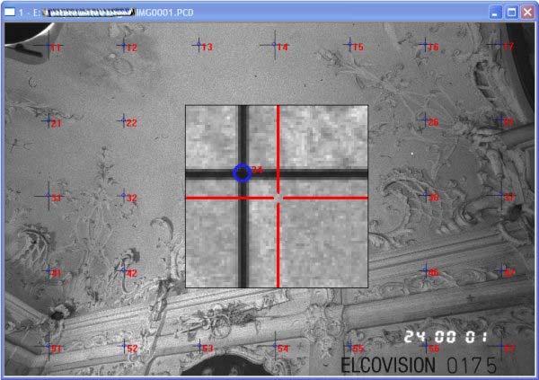
38 Automatic Comparators Stage (comparator) coordinates are measured automatically. The stage is moved in the xy-directions by means of high precision servo-motors. For this type of comparators, we use retroreflective targets: When they are illuminated at the moment of exposure, they produce high contrast to their background. 38
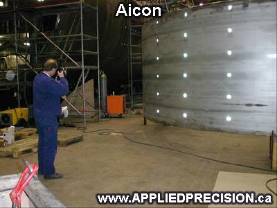
39 Retro-reflective Targets 39


40 Retro-reflective Targets 40
41 Automatic Comparators 41
42 Automatic Comparators Approximate locations of the targets in the image are available. The stage is driven to the approximate locations of the targets. This part of the image is digitized by a CCD camera. Through a simple thresholding and centroid extraction algorithm, one can determine the stage coordinates of the target under consideration. 42


43 Centroid Extraction 43
44 Centroid Extraction x y c c ( ( g ( g g i i ( g i i g g th g th g ) th ) th ) x ) y i i The summation is carried over all the pixels that belong to the blob. 44
45 Coordinate Measurements in Digital Images Pixel Coordinates 45

46 Digital Images Digital images can be obtained through either: Scanning analogue images (Scanners), or Directly using digital cameras. Photogrammetric Scanner 46
47 Digital Cameras A digital camera captures an image through a sensor called CCD (Charge Coupled Devices) or CMOS (Complementary Metal-Oxide Semiconductor). CCD/CMOS is a chip consisting of an array of light sensitive photo-cells. This sensor has light sensing dots called pixels. The actual resolution of a camera is controlled by the total number of pixels that are located on the CCD/CMOS sensor. The more pixels a digital camera has on its sensor, the larger the pictures you can take. 47

48 Digital Mapping Camera (DMC TM ) Digital frame camera developed by Z/I Imaging It is a turnkey digital camera designed to support aerial photogrammetric missions Resolution: 14kx8k 48
 Single PAN CCD and four multispectral cameras 49")
49 Digital Mapping Camera: Z/I DMC IIe 250 Source: Z/I Imaging Z/I DMC IIe 250 (16768x14016 image format) Single PAN CCD and four multispectral cameras 49
50 Digital Images y` Row Column x` Pixel Coordinates are analogous to comparator coordinates. 50
51 Comparator to Image Coordinate Transformation 51
52 Deriving Image Coordinates Comparators measure the coordinates of selected points relative to the comparator coordinate system (x`, y`) comparator/machine coordinates. We are interested in the coordinates of these points w.r.t. the image coordinate system (x, y). Thus, we need to reduce the comparator coordinates into image coordinates. 52
53 Comparator to Image Coordinate Transformation Images Acquired by Analogue Cameras 53
54 Image Coordinate System y Fiducial Mark x 54
55 Fiducial Marks Fiducial marks are small targets on the body of metric cameras. Their positions relative to the camera body are known through a calibration procedure. They define the image coordinate system. In that system, the position of the perspective centre is known. Form, number, and distribution of Fiducial marks depend on the camera manufacturer. 55

56 Sample Fiducial Marks 56
57 Comparator to Image Coordinate Transformation Alternatives: Two dimensional similarity transformation Four parameters Affine transformation Six parameters Bilinear transformation Eight parameters Projective transformation Eight parameters 57
58 2-D Similarity Transformation y y` p x T α x` y T x 58
59 2-D Similarity Transformation y` y y` x x` y x` x x = x` cos( -y` sin() y = x` sin() + y` cos() 59
60 2-D Similarity Transformation x y x y T T S cos sin sin cos x y Where : S x T & y x & y x& y T is a scale factor are shifts is a rotation angle are image coordinates are comparator coordinates 60
61 61 sin cos : S b S a Where y x a b b a y x y x T T 2-D Similarity Transformation
62 Scale Differences along the x and y axes y S y y` p x T α x` S x y T x 62
63 Scale Differences along the x and y axes x y x y T T S S x x cos sin S S y y sin cos x y Where : S S x y is is the the scale scale factor factor along along the the x y axis axis 63
64 Non Orthogonality Between Comparator Axes y S y y` p ( + ) α x` x T S x y T x 64
65 Non Orthogonality Between Comparator Axes x y x y T T S S x x cos( ) sin( ) S S y y sin cos x y Where : S S x y is the scale factor along the x axis is the scale factor along the y axis is the non orthogonal ity angle 65
66 66 Affine Transformation cos ) sin( sin ) cos( : y x T o y x T o o o S b S b y b S a S a x a Where y x b b a a b a y x
67 Bilinear Transformation It can compensate for distortions introduced during film development (e.g., film shrinkage). x = a o + a 1 x` + a 2 y` + a 3 x` y` y = b o + b 1 x` + b 2 y` + b 3 x` y` Number of involved parameters: Eight 67
68 Projective Transformation Stage to image coordinate transformation is a plane to plane transformation. Projective transformation can be used. x = (a o + a 1 x` + a 2 y`) / (1 + c 1 x` + c 2 y`). y = (b o + b 1 x` + b 2 y`) / (1 + c 1 x` + c 2 y`). Number of involved parameters: Eight 68
69 Comparator to Image Coordinate Transformation For metric cameras, the image coordinate system is defined by the Fiducial marks. The image coordinates of the Fiducial marks are available in the camera calibration certificate. Using the image and comparator coordinates of the Fiducial marks, we can compute the transformation parameters. 69
70 Camera Calibration Certificate (CCC) 70
71 Fiducial Marks Coordinates (CCC) ID x-coordinate mm y-coordinate mm
72 Comparator-to-Image Coordinate Transformation Images Acquired by Digital Cameras 72
73 Digital Cameras: Image Coordinate System Fiducial marks are not necessary for digital cameras since the CCD/CMOS sensor is kept fixed relative to the camera body. For imagery acquired by digital cameras, the image coordinate system is defined by: Central rows x-axis Central columns y-axis 73
74 Pixel-to-Image Coordinate Transformation Digital Environment y` y x x` Pixel Coordinates Image Coordinates 74
75 75 Pixel-to-Image Coordinate Transformation direction column the along size Pixel size pix y row direction the along size Pixel size pix x rows of Number n columns of Number n where size pix x x n y size pix y n y x r c r c : ) 2.0 / ( 2.0 ) / (
76 Reduction (Refinement) of Image Coordinates 76
77 Distortion Parameters Distortion parameters compensate for all the deviations from the assumed perspective geometry. Assumed perspective geometry: Object point, perspective center, and the corresponding image point lie on a straight line. Distortions include (for example): Lens distortion (radial & de-centering) Atmospheric refraction Non-planar film platen 77
78 Assumed Perspective Geometry (a) Image Point Perspective Center Straight Line (A) Object Point 78
79 Radial Lens Distortion Radial Lens Distortion Theoretical Light Ray Actual Light Ray 79
80 Radial Lens Distortion The light ray changes its direction after passing through the perspective center. Radial lens distortion is caused by: Large off-axial angle Lens manufacturing flaws Radial lens distortion occurs along a radial direction from the principal point Radial lens distortion increases as we move away from the principal point 80
81 Radial Lens Distortion Fiducial Center Principal Point 81
82 Radial Lens Distortion With distortions Without distortions Pin Cushion Type Radial Lens Distortion 82

83 Radial Lens Distortion Without distortions With distortions Barrel Type Radial Lens Distortion 83


84 Radial Lens Distortion 84
85 Radial Lens Distortion r r y x (y-y p ) (x-x p ) x = r * (x - x p ) / r y = r * (y - y p ) / r 85
86 Radial Lens Distortion Radial lens distortion, r as a function of r, is available in the camera calibration certificate in either one of the following forms: Graphical form, Tabular form, or Polynomial coefficients. Note: r is the radial distance between the principal point and the image point under consideration. 86
87 Radial Lens Distortion x Radial Lens Distortion ( x x p ) ( k 1 r 2 k 2 r 4 k 3 r 6...) y Radial Lens Distortion ( y y p ) ( k 1 r 2 k 2 r 4 k 3 r 6...) where: r = {(x - x p ) 2 + (y - y p ) 2 }

88 After Removing Radial Lens Distortion 88

89 Lens Cone Assembly 89
90 De-centering Lens Distortion De-centering lens distortion is caused by misalignment of the components of the lens system. De-centering lens distortion has two components: Radial component Tangential component 90
91 De-centering Lens Distortion Actual Optical Axis Theoretical Optical Axis 91
92 De-centering Lens Distortion 92
93 De-centering Lens Distortion o P(r) P( r) J 1 r t P( r) 2 r 3 P( r) J 2 r 4 sin( ) cos( )... o o P (r) is the profile along the axis with the maximum tangential distortion. is the direction of the axis with the maximum tangential distortion. 93
94 De-centering Lens Distortion x Decenterin g Lens Distortion (1 p 3 r 2 ){ p 1 ( r 2 2x 2 ) 2 p 2 x y } y Decenterin g Lens Distortion (1 p 3 r 2 ){2 p 1 x y p 2 ( r 2 2 y 2 )} where: r = {(x - x p ) 2 + (y - y p ) 2 } 0.5 x y x y p 1 = -J 1 sin o. p 2 = J 1 cos o. p 3 = J 2 / J x y p p
95 De-centering Lens Distortion Without distortions 95 With distortions
96 Camera Calibration Certificate: Example Wild Heerbrugg Instruments Inc Camera type : Wild RC10 Identification number : 2061 Lens : Wild 15 UAG I Identification Number : 6029 Calibrated Focal Length : C = mm Principal point coordinates in the Fiducial system: x p = mm y p = mm 96
")
97 Camera Calibration Certificate (CCC) 97
98 Fiducial Mark Coordinates (CCC) ID x-coordinate mm y-coordinate mm
99 Camera Calibration Certificate Radial Lens Distortion Coefficients: K 1 = E-08 mm -2 K 2 = E-12 mm -4 K 3 = E-17 mm -6 De-centering Lens Coefficients: P 1 = E-07 mm -1 P 2 = E-06 mm -1 99
100 Atmospheric Refraction The light ray from the object point to the perspective center passes through layers with different temperature, pressure, and humidity. Each layer has its own refractive index. Consequently, the light ray will follow a curved not a straight path. The distortion occurs along the radial direction from the nadir point. It increases as the radial distance increases. 100
101 Atmospheric Refraction Atmospheric Refraction Actual Light Ray Theoretical Light Ray 101
102 Atmospheric Refraction Fiducial Center Nadir Point 102
103 Atmospheric Refraction r = k r {1 + r 2 / c 2 } K is the atmospheric refraction coefficient. Image points are always displaced outwardly along the radial direction. Correction (r) is always negative. The above equation is only valid for almost vertical photography. 103
104 104 level sea the Km above in are Z Z Where Z Z Z Z Z Z Z k o o o o o & : 250) 6 ( ) ( 1) ( c r y k y c r x k x Atmospheric Refraction
105 Earth Curvature It is not a problem with the image formation process (i.e., it is not a deviation from the assumed perspective geometry). It is a problem arising from the way we define the ground coordinate system. If the ground coordinates of the GCP are given relative to a true three-dimensional coordinate system, the curvature of the Earth s surface is already taken into account. 105
106 Earth Curvature If the GCP is given relative to a map coordinate system (e.g., state plane and orthometric height), we have a problem with small scale imagery. The Earth surface as reconstructed from the imagery is a spheroid. The Earth surface as defined by the GCP is flat. In this case, we have to distort the image coordinates in such a way that the Earth surface as reconstructed from the imagery is flat. 106
107 Earth Curvature Earth Curvature Correction (Modification) Theoretical Light Ray Actual Light Ray Assumed Earth Surface Actual Earth Surface 107
108 Earth Curvature If we are dealing with a single image, and if this image is a true vertical image, Then, the image coordinates can be changed to compensate for the effect of Earth curvature In effect, we get the points depicted in the image plane as if the Earth surface had been totally flat. r H r 3 2 R c 2 H flying height, r radial distance from the principal point, R radius of the Earth (6370 Km), c principal distance 108
109 Earth Curvature r is always +ve. Nowadays, the GCP are mainly provided by GPS which provides us with true spatial coordinate system. Thus, we do not need to apply the earth curvature correction (modification). 109
110 Non Planar Film Platen Distortion Actual Film Platen Theoretical Film Platen 110
111 Non Planar Film Platen dh dr r c r/c = dr/dh dr = dh * r/c 111
112 Non Planar Film Platen dh: The deviation of the film platen from a perfect plane. Using height gages, dh can be measured and modeled by a high order polynomial. We can assure that the film is positioned tightly against the focal plane using either: Glass plates (not recommended) Suction mechanisms 112
113 Reseau Camera 113

114 Reseau Camera 114
115 Reseau: A raster of regularly spaced crosses marked on a glass plate in front of the film platen. The images of the crosses will appear on the final image. The image coordinates of the grid elements are available in the Camera Calibration Certificate (CCC). Comparing the image coordinates of the grid elements in both the image and the CCC, we can correct for the distortions that took place during film development. Reseau Camera 115
116 Point Classification Points can be classified according to: How do they appear in the imagery Natural targets Signalized targets Artificial points Their role in the adjustment Control points Check points Tie points 116


117 Natural Targets 117

118 Artificial Points 118


119 Signalized Targets 119

120 Signalized Targets 120

121 Signalized Targets: Preparation 121

122 Signalized Targets 122
123 Point Classification (II) Control Points: points whose ground coordinates are available from geodetic measurements ( e.g., GPS). They are used to define the datum during the bundle adjustment. Origin (three parameters), Orientation in space (three parameters), and Scale (one parameter). A minimum of three non-collinear ground control points is needed to define the datum. 123

124 Ground Control Points: Collection 124
125 Point Classification (II) Tie Points: Their function is to tie together overlapping images. They should be well defined in the images. Their ground coordinates are determined through photogrammetric adjustment. 125


126 Tie Points 126
127 Point Classification (II) Check Points: Points whose ground coordinates are available from geodetic measurements. In the photogrammetric adjustment, they are used as tie points. By comparing the photogrammetric and geodetic coordinates, one can check the quality of the photogrammetric adjustment. 127
Chapters 1 5. Photogrammetry: Definition, introduction, and applications. Electro-magnetic radiation Optics Film development and digital cameras
 Chapters 1 5 Chapter 1: Photogrammetry: Definition, introduction, and applications Chapters 2 4: Electro-magnetic radiation Optics Film development and digital cameras Chapter 5: Vertical imagery: Definitions,
Chapters 1 7: Overview
 Chapters 1 7: Overview Chapter 1: Introduction Chapters 2 4: Data acquisition Chapters 5 7: Data manipulation Chapter 5: Vertical imagery Chapter 6: Image coordinate measurements and refinements Chapter
Chapters 1-4: Summary
 Chapters 1-4: Summary So far, we have been investigating the image acquisition process. Chapter 1: General introduction Chapter 2: Radiation source and properties Chapter 3: Radiation interaction with
Exterior Orientation Parameters
 Exterior Orientation Parameters PERS 12/2001 pp 1321-1332 Karsten Jacobsen, Institute for Photogrammetry and GeoInformation, University of Hannover, Germany The georeference of any photogrammetric product
Photogrammetry: DTM Extraction & Editing
 Photogrammetry: DTM Extraction & Editing How can one determine the x, y, and z of a location? Approaches to DTM Extraction Ground surveying Digitized topographic maps Traditional photogrammetry Hardcopy
TERRESTRIAL AND NUMERICAL PHOTOGRAMMETRY 1. MID -TERM EXAM Question 4
 TERRESTRIAL AND NUMERICAL PHOTOGRAMMETRY 1. MID -TERM EXAM Question 4 23 November 2001 Two-camera stations are located at the ends of a base, which are 191.46m long, measured horizontally. Photographs
Photogrammetry: DTM Extraction & Editing
 Photogrammetry: DTM Extraction & Editing Review of terms Vertical aerial photograph Perspective center Exposure station Fiducial marks Principle point Air base (Exposure Station) Digital Photogrammetry:
Chapters 1 9: Overview
 Chapters 1 9: Overview Chapter 1: Introduction Chapters 2 4: Data acquisition Chapters 5 9: Data manipulation Chapter 5: Vertical imagery Chapter 6: Image coordinate measurements and refinements Chapters
Calibration of IRS-1C PAN-camera
 Calibration of IRS-1C PAN-camera Karsten Jacobsen Institute for Photogrammetry and Engineering Surveys University of Hannover Germany Tel 0049 511 762 2485 Fax -2483 Email karsten@ipi.uni-hannover.de 1.
ADS40 Calibration & Verification Process. Udo Tempelmann*, Ludger Hinsken**, Utz Recke*
 ADS40 Calibration & Verification Process Udo Tempelmann*, Ludger Hinsken**, Utz Recke* *Leica Geosystems GIS & Mapping GmbH, Switzerland **Ludger Hinsken, Author of ORIMA, Konstanz, Germany Keywords: ADS40,
Stereoscopic Models and Plotting
 Stereoscopic Models and Plotting Stereoscopic Viewing Stereoscopic viewing is the way the depth perception of the objects through BINOCULAR vision with much greater accuracy. رؤيه البعد الثالث و االحساس
Introduction Photogrammetry Photos light Gramma drawing Metron measure Basic Definition The art and science of obtaining reliable measurements by mean
 Photogrammetry Review Neil King King and Associates Testing is an art Introduction Read the question Re-Read Read The question What is being asked Answer what is being asked Be in the know Exercise the
POSITIONING A PIXEL IN A COORDINATE SYSTEM
 GEOREFERENCING AND GEOCODING EARTH OBSERVATION IMAGES GABRIEL PARODI STUDY MATERIAL: PRINCIPLES OF REMOTE SENSING AN INTRODUCTORY TEXTBOOK CHAPTER 6 POSITIONING A PIXEL IN A COORDINATE SYSTEM The essential
Laser sensors. Transmitter. Receiver. Basilio Bona ROBOTICA 03CFIOR
 Mobile & Service Robotics Sensors for Robotics 3 Laser sensors Rays are transmitted and received coaxially The target is illuminated by collimated rays The receiver measures the time of flight (back and
Lecture 5. Relief displacement. Parallax. Monoscopic and stereoscopic height measurement. Photo Project. Soft-copy Photogrammetry.
 NRMT 2270, Photogrammetry/Remote Sensing Lecture 5 Relief displacement. Parallax. Monoscopic and stereoscopic height measurement. Photo Project. Soft-copy Photogrammetry. Tomislav Sapic GIS Technologist
Elements of Analytical Photogrammetry
 Chapter 5 Elements of Analytical hotogrammetry 5.1 Introduction, Concept of Image and Object Space hotogrammetry is the science of obtaining reliable information about objects and of measuring and interpreting
IMAGE ACQUISITION FOR DIGITAL PHOTOGRAMMETRY USING OF THE SHELF AND METRIC CAMERAS
 IMAGE ACQUISITION FOR DIGITAL PHOTOGRAMMETRY USING OF THE SHELF AND METRIC CAMERAS Günter Pomaska FH Bielefeld, University of Applied Sciences Artilleriestr. 9, D32427 Minden gp@imagefact.de, www.imagefact.de
Geometry of Aerial photogrammetry. Panu Srestasathiern, PhD. Researcher Geo-Informatics and Space Technology Development Agency (Public Organization)
") Geometry of Aerial photogrammetry Panu Srestasathiern, PhD. Researcher Geo-Informatics and Space Technology Development Agency (Public Organization) Image formation - Recap The geometry of imaging system
Geometry of Aerial photogrammetry Panu Srestasathiern, PhD. Researcher Geo-Informatics and Space Technology Development Agency (Public Organization) Image formation - Recap The geometry of imaging system
Chapter 1: Overview. Photogrammetry: Introduction & Applications Photogrammetric tools:
 Chapter 1: Overview Photogrammetry: Introduction & Applications Photogrammetric tools: Rotation matrices Photogrammetric point positioning Photogrammetric bundle adjustment This chapter will cover the
Training i Course Remote Sensing Basic Theory & Image Processing Methods September 2011
 Training i Course Remote Sensing Basic Theory & Image Processing Methods 19 23 September 2011 Geometric Operations Michiel Damen (September 2011) damen@itc.nl ITC FACULTY OF GEO-INFORMATION SCIENCE AND
Camera model and multiple view geometry
 Chapter Camera model and multiple view geometry Before discussing how D information can be obtained from images it is important to know how images are formed First the camera model is introduced and then
BUNDLE BLOCK ADJUSTMENT WITH HIGH RESOLUTION ULTRACAMD IMAGES
 BUNDLE BLOCK ADJUSTMENT WITH HIGH RESOLUTION ULTRACAMD IMAGES I. Baz*, G. Buyuksalih*, K. Jacobsen** * BIMTAS, Tophanelioglu Cad. ISKI Hizmet Binasi No:62 K.3-4 34460 Altunizade-Istanbul, Turkey gb@bimtas.com.tr
Extracting Elevation from Air Photos
 Extracting Elevation from Air Photos TUTORIAL A digital elevation model (DEM) is a digital raster surface representing the elevations of a terrain for all spatial ground positions in the image. Traditionally
Basilio Bona DAUIN Politecnico di Torino
 ROBOTICA 03CFIOR DAUIN Politecnico di Torino Mobile & Service Robotics Sensors for Robotics 3 Laser sensors Rays are transmitted and received coaxially The target is illuminated by collimated rays The
Terrain correction. Backward geocoding. Terrain correction and ortho-rectification. Why geometric terrain correction? Rüdiger Gens
 Terrain correction and ortho-rectification Terrain correction Rüdiger Gens Why geometric terrain correction? Backward geocoding remove effects of side looking geometry of SAR images necessary step to allow
University of Technology Building & Construction Department / Remote Sensing & GIS lecture
 5. Corrections 5.1 Introduction 5.2 Radiometric Correction 5.3 Geometric corrections 5.3.1 Systematic distortions 5.3.2 Nonsystematic distortions 5.4 Image Rectification 5.5 Ground Control Points (GCPs)
Integrating the Generations, FIG Working Week 2008,Stockholm, Sweden June 2008
 H. Murat Yilmaz, Aksaray University,Turkey Omer Mutluoglu, Selçuk University, Turkey Murat Yakar, Selçuk University,Turkey Cutting and filling volume calculation are important issues in many engineering
STRAIGHT LINE REFERENCE SYSTEM STATUS REPORT ON POISSON SYSTEM CALIBRATION
 STRAIGHT LINE REFERENCE SYSTEM STATUS REPORT ON POISSON SYSTEM CALIBRATION C. Schwalm, DESY, Hamburg, Germany Abstract For the Alignment of the European XFEL, a Straight Line Reference System will be used
RESAMPLING DIGITAL IMAGERY TO EPIPOLAR GEOMETRY
 RESAMPLING DIGITAL IMAGERY TO EPIPOLAR GEOMETRY Woosug Cho Toni Schenk Department of Geodetic Science and Surveying The Ohio State University, Columbus, Ohio 43210-1247 USA Mustafa Madani Intergraph Corporation,
Map Compilation CHAPTER HISTORY
 CHAPTER 7 Map Compilation 7.1 HISTORY Producing accurate commercial maps from aerial photography began in the 1930s. The technology of stereomapping over the last 70 years has brought vast technological
Geometric Accuracy Evaluation, DEM Generation and Validation for SPOT-5 Level 1B Stereo Scene
 Geometric Accuracy Evaluation, DEM Generation and Validation for SPOT-5 Level 1B Stereo Scene Buyuksalih, G.*, Oruc, M.*, Topan, H.*,.*, Jacobsen, K.** * Karaelmas University Zonguldak, Turkey **University
Creating a distortion characterisation dataset for visual band cameras using fiducial markers.
 Creating a distortion characterisation dataset for visual band cameras using fiducial markers. Robert Jermy Council for Scientific and Industrial Research Email: rjermy@csir.co.za Jason de Villiers Council
Low-Cost Orthophoto Production Using OrthoMapper Software
 Low-Cost Orthophoto Production Using OrthoMapper Software Rick Day Penn State Cooperative Extension, Geospatial Technology Program, RGIS-Chesapeake Air Photos Historical air photos are available from a
ACCURACY ANALYSIS FOR NEW CLOSE-RANGE PHOTOGRAMMETRIC SYSTEMS
 ACCURACY ANALYSIS FOR NEW CLOSE-RANGE PHOTOGRAMMETRIC SYSTEMS Dr. Mahmoud El-Nokrashy O. ALI Prof. of Photogrammetry, Civil Eng. Al Azhar University, Cairo, Egypt m_ali@starnet.com.eg Dr. Mohamed Ashraf
Centre for Digital Image Measurement and Analysis, School of Engineering, City University, Northampton Square, London, ECIV OHB
 HIGH ACCURACY 3-D MEASUREMENT USING MULTIPLE CAMERA VIEWS T.A. Clarke, T.J. Ellis, & S. Robson. High accuracy measurement of industrially produced objects is becoming increasingly important. The techniques
CS6670: Computer Vision
 CS6670: Computer Vision Noah Snavely Lecture 5: Projection Reading: Szeliski 2.1 Projection Reading: Szeliski 2.1 Projection Müller Lyer Illusion http://www.michaelbach.de/ot/sze_muelue/index.html Modeling
Ch 22 Inspection Technologies
 Ch 22 Inspection Technologies Sections: 1. Inspection Metrology 2. Contact vs. Noncontact Inspection Techniques 3. Conventional Measuring and Gaging Techniques 4. Coordinate Measuring Machines 5. Surface
GALILEO SISCAM APPROACH TO DIGITAL PHOTOGRAMMETRY. F. Flamigni A. Viti Galileo Siscam S.p.A.
 GALILEO SISCAM APPROACH TO DIGITAL PHOTOGRAMMETRY F. Flamigni A. Viti Galileo Siscam S.p.A. ABSTRACT: The application of the least squares matching procedure to an analytical stereoplotter is described.
COORDINATE TRANSFORMATION. Lecture 6
 COORDINATE TRANSFORMATION Lecture 6 SGU 1053 SURVEY COMPUTATION 1 Introduction Geomatic professional are mostly confronted in their work with transformations from one two/three-dimensional coordinate system
HOUGH TRANSFORM FOR INTERIOR ORIENTATION IN DIGITAL PHOTOGRAMMETRY
 HOUGH TRANSFORM FOR INTERIOR ORIENTATION IN DIGITAL PHOTOGRAMMETRY Sohn, Hong-Gyoo, Yun, Kong-Hyun Yonsei University, Korea Department of Civil Engineering sohn1@yonsei.ac.kr ykh1207@yonsei.ac.kr Yu, Kiyun
Sensor technology for mobile robots
 Laser application, vision application, sonar application and sensor fusion (6wasserf@informatik.uni-hamburg.de) Outline Introduction Mobile robots perception Definitions Sensor classification Sensor Performance
ECE-161C Cameras. Nuno Vasconcelos ECE Department, UCSD
 ECE-161C Cameras Nuno Vasconcelos ECE Department, UCSD Image formation all image understanding starts with understanding of image formation: projection of a scene from 3D world into image on 2D plane 2
Measurement of Direction: Bearing vs. Azimuth
 Week 5 Monday Measurement of Direction: Bearing vs. Azimuth Bearing Is an angle of 90 o or less Measured from either North or South in easterly & westerly directions. North 22 o West, South 89 o West,
PREPARATIONS FOR THE ON-ORBIT GEOMETRIC CALIBRATION OF THE ORBVIEW 3 AND 4 SATELLITES
 PREPARATIONS FOR THE ON-ORBIT GEOMETRIC CALIBRATION OF THE ORBVIEW 3 AND 4 SATELLITES David Mulawa, Ph.D. ORBIMAGE mulawa.david@orbimage.com KEY WORDS: Geometric, Camera, Calibration, and Satellite ABSTRACT
Phototriangulation Introduction
 Introduction Photogrammetry aims to the reconstruction of the 3D object-space from the 2D image-space, thus leading to the computation of reliable, indirect measurements of 3D coordinates in the object-space
Rectification and Distortion Correction
 Rectification and Distortion Correction Hagen Spies March 12, 2003 Computer Vision Laboratory Department of Electrical Engineering Linköping University, Sweden Contents Distortion Correction Rectification
PART A Three-Dimensional Measurement with iwitness
 PART A Three-Dimensional Measurement with iwitness A1. The Basic Process The iwitness software system enables a user to convert two-dimensional (2D) coordinate (x,y) information of feature points on an
DIGITAL SURFACE MODELS OF CITY AREAS BY VERY HIGH RESOLUTION SPACE IMAGERY
 DIGITAL SURFACE MODELS OF CITY AREAS BY VERY HIGH RESOLUTION SPACE IMAGERY Jacobsen, K. University of Hannover, Institute of Photogrammetry and Geoinformation, Nienburger Str.1, D30167 Hannover phone +49
GEOMETRIC POTENTIAL OF IRS-1 C PAN-CAMERA. Jacobsen, Karsten University of Hannover
 GEOMETRIC POTENTIAL OF IRS-1 C PAN-CAMERA Jacobsen, Karsten University of Hannover Email: karsten@ipi.uni-hannover.de KEY WORDS: Geometry, IRS1-C, block adjustment ABSTRACT: IRS-1 C images with optimal
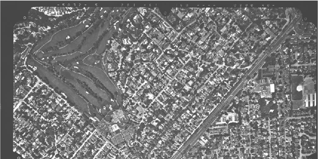
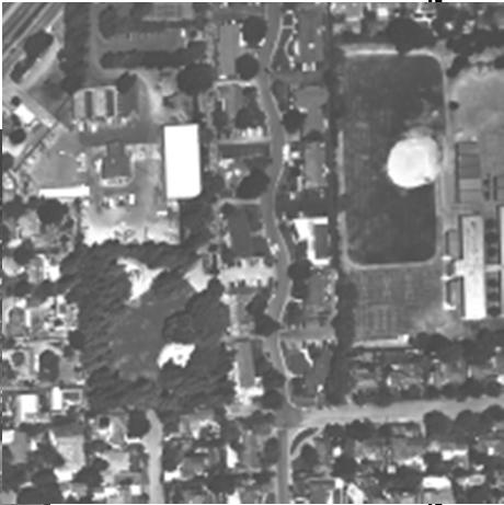
Index Mosaic of 1999 Purdue Block: 80% Forward Overlap and 60% Side Overlap (usual is 60/30!) Many trees show that October is not best time.
 Many trees show that October is not best time.") Index Mosaic of 1999 Purdue Block: 80% Forward Overlap and 60% Side Overlap (usual is 60/30!) Many trees show that October is not best time. HYMAP Data, Summer 1999 Tying Block to Reference Coordinate
Index Mosaic of 1999 Purdue Block: 80% Forward Overlap and 60% Side Overlap (usual is 60/30!) Many trees show that October is not best time. HYMAP Data, Summer 1999 Tying Block to Reference Coordinate
ifp Universität Stuttgart Performance of IGI AEROcontrol-IId GPS/Inertial System Final Report
 Universität Stuttgart Performance of IGI AEROcontrol-IId GPS/Inertial System Final Report Institute for Photogrammetry (ifp) University of Stuttgart ifp Geschwister-Scholl-Str. 24 D M. Cramer: Final report
Range Sensors (time of flight) (1)
 (1)") Range Sensors (time of flight) (1) Large range distance measurement -> called range sensors Range information: key element for localization and environment modeling Ultrasonic sensors, infra-red sensors
Range Sensors (time of flight) (1) Large range distance measurement -> called range sensors Range information: key element for localization and environment modeling Ultrasonic sensors, infra-red sensors
Digital Image Processing COSC 6380/4393
 Digital Image Processing COSC 6380/4393 Lecture 4 Jan. 24 th, 2019 Slides from Dr. Shishir K Shah and Frank (Qingzhong) Liu Digital Image Processing COSC 6380/4393 TA - Office: PGH 231 (Update) Shikha
Camera Calibration for Video See-Through Head-Mounted Display. Abstract. 1.0 Introduction. Mike Bajura July 7, 1993
 Camera Calibration for Video See-Through Head-Mounted Display Mike Bajura July 7, 1993 Abstract This report describes a method for computing the parameters needed to model a television camera for video
UNIT-2 IMAGE REPRESENTATION IMAGE REPRESENTATION IMAGE SENSORS IMAGE SENSORS- FLEX CIRCUIT ASSEMBLY
 18-08-2016 UNIT-2 In the following slides we will consider what is involved in capturing a digital image of a real-world scene Image sensing and representation Image Acquisition Sampling and quantisation
٥...: (Picture element) Pixel ٧...:
 Pixel ٧...:") ( RS ) : : / : : - ٣... : ٣...: ٤...: ٥...: (Picture element) Pixel ٥...: ٧...: ١٠... : Geo Tiff ١٨... : ١٩... : DEM ٢٨...: ٢ :.. " " RS. :.. Kosmos Land Sat. : : RS :. : (Land Use) :( Change detection
( RS ) : : / : : - ٣... : ٣...: ٤...: ٥...: (Picture element) Pixel ٥...: ٧...: ١٠... : Geo Tiff ١٨... : ١٩... : DEM ٢٨...: ٢ :.. " " RS. :.. Kosmos Land Sat. : : RS :. : (Land Use) :( Change detection
3D-OBJECT DETECTION METHOD BASED ON THE STEREO IMAGE TRANSFORMATION TO THE COMMON OBSERVATION POINT
 3D-OBJECT DETECTION METHOD BASED ON THE STEREO IMAGE TRANSFORMATION TO THE COMMON OBSERVATION POINT V. M. Lisitsyn *, S. V. Tikhonova ** State Research Institute of Aviation Systems, Moscow, Russia * lvm@gosniias.msk.ru
GEOMETRIC ASPECTS CONCERNING THE PHOTOGRAMMETRIC WORKFLOW OF THE DIGITAL AERIAL CAMERA ULTRACAM X
 GEOMETRIC ASPECTS CONCERNING THE PHOTOGRAMMETRIC WORKFLOW OF THE DIGITAL AERIAL CAMERA ULTRACAM X Richard Ladstädter a, Michael Gruber b a Institute of Remote Sensing and Photogrammetry, Graz University
Image georeferencing is the process of developing a model to transform from pixel coordinates into GIS coordinates such as meters on the ground.
 Image georeferencing is the process of developing a model to transform from pixel coordinates into GIS coordinates such as meters on the ground. Image rectification is the process of using your georeferencing
DESIGN AND TESTING OF MATHEMATICAL MODELS FOR A FULL-SPHERICAL CAMERA ON THE BASIS OF A ROTATING LINEAR ARRAY SENSOR AND A FISHEYE LENS
 DESIGN AND TESTING OF MATHEMATICAL MODELS FOR A FULL-SPHERICAL CAMERA ON THE BASIS OF A ROTATING LINEAR ARRAY SENSOR AND A FISHEYE LENS Danilo SCHNEIDER, Ellen SCHWALBE Institute of Photogrammetry and
10/5/09 1. d = 2. Range Sensors (time of flight) (2) Ultrasonic Sensor (time of flight, sound) (1) Ultrasonic Sensor (time of flight, sound) (2) 4.1.
 (2) Ultrasonic Sensor (time of flight, sound) (1) Ultrasonic Sensor (time of flight, sound) (2) 4.1.") Range Sensors (time of flight) (1) Range Sensors (time of flight) (2) arge range distance measurement -> called range sensors Range information: key element for localization and environment modeling Ultrasonic
Range Sensors (time of flight) (1) Range Sensors (time of flight) (2) arge range distance measurement -> called range sensors Range information: key element for localization and environment modeling Ultrasonic
Rodenstock Products Photo Optics / Digital Imaging
 Go to: Apo-Sironar digital Apo-Macro-Sironar digital Apo-Sironar digital HR Lenses for Digital Professional Photography Digital photography may be superior to conventional photography if the end-product
Measurement and Precision Analysis of Exterior Orientation Element Based on Landmark Point Auxiliary Orientation
 2016 rd International Conference on Engineering Technology and Application (ICETA 2016) ISBN: 978-1-60595-8-0 Measurement and Precision Analysis of Exterior Orientation Element Based on Landmark Point
DIGITAL ORTHOPHOTO GENERATION
 DIGITAL ORTHOPHOTO GENERATION Manuel JAUREGUI, José VÍLCHE, Leira CHACÓN. Universit of Los Andes, Venezuela Engineering Facult, Photogramdemr Institute, Email leirac@ing.ula.ven Working Group IV/2 KEY
LPS Project Manager User s Guide. November 2009
 LPS Project Manager User s Guide November 2009 Copyright 2009 ERDAS, Inc. All rights reserved. Printed in the United States of America. The information contained in this document is the exclusive property
Homogeneous Coordinates. Lecture18: Camera Models. Representation of Line and Point in 2D. Cross Product. Overall scaling is NOT important.
 Homogeneous Coordinates Overall scaling is NOT important. CSED44:Introduction to Computer Vision (207F) Lecture8: Camera Models Bohyung Han CSE, POSTECH bhhan@postech.ac.kr (",, ) ()", ), )) ) 0 It is
COMPARATIVE ANALYSIS OF ALTERNATIVE IN-DOOR CALIBRATION TECHNIQUES FOR OFF-THE-SHELF DIGITAL CAMERAS INTRODUCTION
 COMPARATIVE ANALYSIS OF ALTERNATIVE IN-DOOR CALIBRATION TECHNIQUES FOR OFF-THE-SHELF DIGITAL CAMERAS Ivan Detchev, Axel Ebeling, Ayman Habib Department of Geomatics Engineering, University of Calgary,
KEY WORDS: IKONOS, Orthophotos, Relief Displacement, Affine Transformation
 GRATIO OF DIGITAL ORTHOPHOTOS FROM IKOOS GO IMAGS Liang-Chien Chen and Chiu-Yueh Lo Center for Space and Remote Sensing Research. ational Central University Tel: 886-3-47151 xt.76 Fax: 886-3-455535 lcchen@csrsr.ncu.edu.tw
PLS - EXAMINATION PREPARATION PHOTOGRAMMETRY 101. A paper on the principles of photogrammetric mapping
 Photogrammetric Consultants PLS - EXAMINATION PREPARATION PHOTOGRAMMETRY 101 A paper on the principles of photogrammetric mapping Photogrammetry is the art and science of obtaining reliable measurements
MODEL DEFORMATION ACCURACY OF DIGITAL FRAME CAMERAS
 MODEL DEFORMATION ACCURACY OF DIGITAL FRAME CAMERAS V. Spreckels a, A. Schlienkamp a, K. Jacobsen b a Deutsche Steinkohle AG (DSK), Dept. Geoinformation/Engineering Survey BG G, Shamrockring 1, D-44623
Geometric Correction
 CEE 6150: Digital Image Processing Geometric Correction 1 Sources of Distortion Sensor Characteristics optical distortion aspect ratio non-linear mirror velocity detector geometry & scanning sequence Viewing
Automatic Systems for Digitizing Historical Maps
 Martina Ballarin *, Caterina Balletti **, Caterina Gottardi *** Automatic Systems for Digitizing Historical Maps Keywords: digitization; robotic arm; 3D recording; photogrammetry; historical maps Summary:
DEVELOPMENT OF CAMERA MODEL AND GEOMETRIC CALIBRATION/VALIDATION OF XSAT IRIS IMAGERY
 DEVELOPMENT OF CAMERA MODEL AND GEOMETRIC CALIBRATION/VALIDATION OF XSAT IRIS IMAGERY Leong Keong Kwoh, Xiaojing Huang, Wee Juan Tan Centre for Remote, Imaging Sensing and Processing (CRISP), National
OMC Camera Calibration Software Guide. Version March 2001
 OMC Camera Calibration Software Guide Version 2.21 March 2001 Copyright OMC 2000-2001 Page 1 Table of contents Cover page 1 Table of contents 2 1. Introduction 3 2. The physical model used in camera calibration
Paraxial into real surfaces
 Paraxial into real surfaces Curvature, Radius Power lens and mirrors lens maker equation mirror and lens in contact Principle planes Real Surfaces Refractive via Fermat s Principle Calculate optical path
GEOMETRY OF DIGITAL FRAME CAMERAS INTRODUCTION
 GEOMETRY OF DIGITAL FRAME CAMERAS Karsten Jacobsen Institute of Photogrammetry and Geoinformation Leibniz University Hannover Nienburger Str. 1, D-30167 Hannover, Germany jacobsen@ipi.uni-hannover.de Keywords:
Geometric Rectification of Remote Sensing Images
 Geometric Rectification of Remote Sensing Images Airborne TerrestriaL Applications Sensor (ATLAS) Nine flight paths were recorded over the city of Providence. 1 True color ATLAS image (bands 4, 2, 1 in
PERFORMANCE OF LARGE-FORMAT DIGITAL CAMERAS
 PERFORMANCE OF LARGE-FORMAT DIGITAL CAMERAS K. Jacobsen Institute of Photogrammetry and GeoInformation, Leibniz University Hannover, Germany jacobsen@ipi.uni-hannover.de Inter-commission WG III/I KEY WORDS:
6. Rectification 2 hours
 Lecture 6-1 - 11/2/2003 Concept Hell/Pfeiffer February 2003 6. ectification 2 hours Aim: Principles for rectification Theory: Indirect rectification in digital image processing Methods of rectification
DD2423 Image Analysis and Computer Vision IMAGE FORMATION. Computational Vision and Active Perception School of Computer Science and Communication
 DD2423 Image Analysis and Computer Vision IMAGE FORMATION Mårten Björkman Computational Vision and Active Perception School of Computer Science and Communication November 8, 2013 1 Image formation Goal:
DEVELOPMENT OF ORIENTATION AND DEM/ORTHOIMAGE GENERATION PROGRAM FOR ALOS PRISM
 DEVELOPMENT OF ORIENTATION AND DEM/ORTHOIMAGE GENERATION PROGRAM FOR ALOS PRISM Izumi KAMIYA Geographical Survey Institute 1, Kitasato, Tsukuba 305-0811 Japan Tel: (81)-29-864-5944 Fax: (81)-29-864-2655
Digital Photogrammetric System. Version 6.3 USER MANUAL. Aerial triangulation
 Digital Photogrammetric System Version 6.3 USER MANUAL Table of Contents 1. Purpose of the document... 5 2. data... 5 2.1. The Orientation menu... 5 2.2. Source data... 7 2.3. workflow... 8 2.4. Data quality
Digital Image Correlation of Stereoscopic Images for Radial Metrology
 Digital Image Correlation of Stereoscopic Images for Radial Metrology John A. Gilbert Professor of Mechanical Engineering University of Alabama in Huntsville Huntsville, AL 35899 Donald R. Matthys Professor
Computer Vision Projective Geometry and Calibration. Pinhole cameras
 Computer Vision Projective Geometry and Calibration Professor Hager http://www.cs.jhu.edu/~hager Jason Corso http://www.cs.jhu.edu/~jcorso. Pinhole cameras Abstract camera model - box with a small hole
Overview. Image Geometric Correction. LA502 Special Studies Remote Sensing. Why Geometric Correction?
 LA502 Special Studies Remote Sensing Image Geometric Correction Department of Landscape Architecture Faculty of Environmental Design King AbdulAziz University Room 103 Overview Image rectification Geometric
Application Note. Revision 1
 Risley Prism Scanner Two wedge prisms can be used to create an angular deviation of a beam from its optical axis to create continuous circular scan patterns or discrete beam pointing, which is commonly
HIGH PRECISION SURVEY AND ALIGNMENT OF LARGE LINEAR COLLIDERS - HORIZONTAL ALIGNMENT -
 HIGH PRECISION SURVEY AND ALIGNMENT OF LARGE LINEAR COLLIDERS - HORIZONTAL ALIGNMENT - A. Herty, J. Albert 1 Deutsches Elektronen-Synchrotron DESY, Hamburg, Germany with international partners * 1. INTRODUCTION
AUTOMATED CALIBRATION TECHNIQUE FOR PHOTOGRAMMETRIC SYSTEM BASED ON A MULTI-MEDIA PROJECTOR AND A CCD CAMERA
 AUTOMATED CALIBRATION TECHNIQUE FOR PHOTOGRAMMETRIC SYSTEM BASED ON A MULTI-MEDIA PROJECTOR AND A CCD CAMERA V. A. Knyaz * GosNIIAS, State Research Institute of Aviation System, 539 Moscow, Russia knyaz@gosniias.ru
GEOMETRY AND INFORMATION CONTENTS OF LARGE SIZE DIGITAL FRAME CAMERAS
 GEOMETRY AND INFORMATION CONTENTS OF LARGE SIZE DIGITAL FRAME CAMERAS Karsten Jacobsen Institute of Photogrammetry and Geoinformation Leibniz University Hannover jacobsen@ipi.uni-hannover.de KEY WORDS:
Close-Range. Photogrammetry. and 3D Imaging. 2nd edition. Edited by. Thomas Luhmann, Stuart Robson, Stephen Kyle. and Jan Boehm.
 Close-Range Photogrammetry and 3D Imaging 2nd edition Edited by Thomas Luhmann, Stuart Robson, Stephen Kyle and Jan Boehm De Gruyter Content 1 Introduction 1 1.1 Overview 1 1.1.1 Content 1 1.1.2 References
Robot Vision: Camera calibration
 Robot Vision: Camera calibration Ass.Prof. Friedrich Fraundorfer SS 201 1 Outline Camera calibration Cameras with lenses Properties of real lenses (distortions, focal length, field-of-view) Calibration
QUALITY CHECK OF MOMS-2P ORTHOIMAGES OF SEMI-ARID LANDSCAPES
 QUALIT CHECK OF MOMS-2P ORTHOIMAGES OF SEMI-ARID LANDSCAPES Manfred Lehner, Rupert Müller German Aerospace Center (DLR), Remote Sensing Technology Institute, D-82234 Wessling, Germany Email: Manfred.Lehner@dlr.de,
TRAINING MATERIAL HOW TO OPTIMIZE ACCURACY WITH CORRELATOR3D
 TRAINING MATERIAL WITH CORRELATOR3D Page2 Contents 1. UNDERSTANDING INPUT DATA REQUIREMENTS... 4 1.1 What is Aerial Triangulation?... 4 1.2 Recommended Flight Configuration... 4 1.3 Data Requirements for
Using Hierarchical Warp Stereo for Topography. Introduction
 Using Hierarchical Warp Stereo for Topography Dr. Daniel Filiberti ECE/OPTI 531 Image Processing Lab for Remote Sensing Introduction Topography from Stereo Given a set of stereoscopic imagery, two perspective
Journal Online Jaringan COT POLIPD (JOJAPS) Accuracy Assessment of Height Coordinate Using Unmanned Aerial Vehicle Images Based On Leveling Height
 Accuracy Assessment of Height Coordinate Using Unmanned Aerial Vehicle Images Based On Leveling Height") JOJAPS eissn 2504-8457 Abstract Journal Online Jaringan COT POLIPD (JOJAPS) Accuracy Assessment of Height Coordinate Using Unmanned Aerial Vehicle Images Based On Leveling Height Syamsul Anuar Bin Abu
JOJAPS eissn 2504-8457 Abstract Journal Online Jaringan COT POLIPD (JOJAPS) Accuracy Assessment of Height Coordinate Using Unmanned Aerial Vehicle Images Based On Leveling Height Syamsul Anuar Bin Abu
MONO-IMAGE INTERSECTION FOR ORTHOIMAGE REVISION
 MONO-IMAGE INTERSECTION FOR ORTHOIMAGE REVISION Mohamed Ibrahim Zahran Associate Professor of Surveying and Photogrammetry Faculty of Engineering at Shoubra, Benha University ABSTRACT This research addresses
GEOMETRIC AND MAPPING POTENTIAL OF WORLDVIEW-1 IMAGES
 GEOMETRIC AND MAPPING POTENTIAL OF WORLDVIEW-1 IMAGES G. Buyuksalih*, I. Baz*, S. Bayburt*, K. Jacobsen**, M. Alkan *** * BIMTAS, Tophanelioglu Cad. ISKI Hizmet Binasi No:62 K.3-4 34460 Altunizade-Istanbul,
REGISTRATION OF AIRBORNE LASER DATA TO SURFACES GENERATED BY PHOTOGRAMMETRIC MEANS. Y. Postolov, A. Krupnik, K. McIntosh
 REGISTRATION OF AIRBORNE LASER DATA TO SURFACES GENERATED BY PHOTOGRAMMETRIC MEANS Y. Postolov, A. Krupnik, K. McIntosh Department of Civil Engineering, Technion Israel Institute of Technology, Haifa,
PROBLEMS AND LIMITATIONS OF SATELLITE IMAGE ORIENTATION FOR DETERMINATION OF HEIGHT MODELS
 PROBLEMS AND LIMITATIONS OF SATELLITE IMAGE ORIENTATION FOR DETERMINATION OF HEIGHT MODELS K. Jacobsen Institute of Photogrammetry and GeoInformation, Leibniz University Hannover, Germany jacobsen@ipi.uni-hannover.de
And. Modal Analysis. Using. VIC-3D-HS, High Speed 3D Digital Image Correlation System. Indian Institute of Technology New Delhi
 Full Field Displacement And Strain Measurement And Modal Analysis Using VIC-3D-HS, High Speed 3D Digital Image Correlation System At Indian Institute of Technology New Delhi VIC-3D, 3D Digital Image Correlation