A Finite Element Approach to Stress Analysis of Face Gears
|
|
|
- Barnaby Underwood
- 5 years ago
- Views:
Transcription


1 Cleveland State University ETD Archive 2012 A Finite Element Approach to Stress Analysis of Face Gears Lokamanya Siva Manohar Rampilla Cleveland State University Follow this and additional works at: Part of the Mechanical Engineering Commons How does access to this work benefit you? Let us know! Recommended Citation Rampilla, Lokamanya Siva Manohar, "A Finite Element Approach to Stress Analysis of Face Gears" (2012). ETD Archive This Thesis is brought to you for free and open access by EngagedScholarship@CSU. It has been accepted for inclusion in ETD Archive by an authorized administrator of EngagedScholarship@CSU. For more information, please contact library.es@csuohio.edu.
2 A FINITE ELEMENT APPROACH TO STRESS ANALYSIS OF FACE GEARS LOKAMANYA SIVA MANOHAR RAMPILLA Bachelor of Mechanical Engineering Jawaharlal Nehru Technological University, India May, 2008 submitted in partial fulfillment of requirements for the degree MASTER OF SCIENCE IN MECHANICAL ENGINEERING at the CLEVELAND STATE UNIVERSITY May, 2012
3 This thesis has been approved for the Department of MECHANICAL ENGINEERING and the College of Graduate Studies by Thesis Committee Chairperson, Dr. Majid Rashidi Department/Date Dr. Rama S. R. Gorla Department/Date Dr. Asuquo Ebiana Department/Date
4 ACKNOWLEDGEMENT Foremost, I would like to express my sincere gratitude to my advisor Dr. Majid Rashidi for the continuous support of my thesis, for his patience, motivation, enthusiasm, and immense knowledge. His guidance helped me in all the time of my research and writing of this thesis. I could not have imagined having a better advisor and mentor for my thesis. Besides my advisor, I would like to thank my thesis committee members: Dr. Rama Gorla and Dr. Asuquo Ebiana, for their encouragement, insightful comments, and helpful questions. My sincere thanks also goes to Dr. Claude Gosslin for helping me with his HyGears software, which is the best software I have ever seen. I could not imagine how tough it would be without his support. I thank my friends Sowmya Reddy Narala, Deepak Ravipati, Prabhu Saran Konduru for the stimulating discussions, and their continuous push and for all the fun we have had in the last two years. Last but not the least, I would like to thank my family: my parents Rama Mohan Rao and Lavanya Sundari, for giving birth to me at the first place and my brother Bhargav Venkata Manohar for supporting me throughout my life.
5 A FINITE ELEMENT APPROACH TO STRESS ANALYSIS OF FACE GEARS LOKAMANYA SIVA MANOHAR RAMPILLA ABSTRACT Face Gears have alternative gear-teeth configuration compared to Bevel Gears. Face Gear have a standard spur pinion as opposed to a bevel Gear. This work concentrates on modeling of a Facegear, Meshed with a spur gear, using CAD Software and Finite Elements Analysis. The bending stress developed at the gear teeth is determined. Numerical results are validated using the bending stress developed between two involute spur gears. iv
6 TABLE OF CONTENTS Page ABSTRACT... IV LIST OF FIGURES... VI I INTRODUCTION Previous Works Advantages of Face Gears over Bevel Gears My Contribution... 6 II VALIDATION of results for bending stress offace gear Validation Of Bending Stress Results Using Lewis Formula And Solidworks Simulation AS Per AGMA Standards... 7 III HYGEARS Introduction To HyGears Gear Design IV RESULTS V CONCLUSION AND FUTURE SCOPE Conclusion Future Scope BIBLIOGRAPHY v
7 LIST OF FIGURES Figure Page Figure 1: Face gear set terminology... 1 Figure 2: Off-set Face gear set... 2 Figure 3: Face gear teeth... 3 Figure 4: Planet gear developed using Hygears Figure 5: Helical Bevel Gear Figure 6: Bevel gear compared to the real manufactured gear with the gear generated using hygear vi

8 CHAPTER I INTRODUCTION Face gears are the kinds of gears which can mesh with either spur or helical pinions having cylindrical base surfaces and the terminology of Face Gear set is shown in Figure 1. The axes of the gear and the pinion generally, but not necessarily, intersect at the right angles. When the axes intersect at right angles the gear set is called On-Center face gear or else the gear set is called off-set face gear as shown in Figure 2. Figure 1: Face gear set terminology
9 Figure 2: Off-set Face gear set In this thesis we will be dealing with the On-center gear set, where the axes intersect and are perpendicular with each other. Face Gear set consists of a spur or a helical pinion that is in mesh with a face gear. The pinions are really not any different from their parallel axis counterparts except for the fact that they are in mesh with a face gear and involute spur gear. Face gears have teeth cut into the blank such that the axis of the teeth lies in a plane that is perpendicular to the shaft axis. The mating pinion is either a spur or a helical gear. The pinion and face 2

10 gear axes most often form a 90ᵒ are possible. In operation, this type of gear is similar to an equivalent set of straight gears. The face gear tooth changes shape from one end of the tooth along the radius of the face of the gear as shown in Fig 3. The load capacity of face gearset, compared with that of bevel gears, is less, thus they are used mostly used as motion transmission gears rather than as power gears. Face gearsets arerelatively easy to make and less expensive compared to the bevel gears. But the calculations involved in designing the face gear set are more complex in nature, because of the change in face width, undercutting and pointing. There were some initial works done in 1950's and 1960's in Russia [1] [2]. Also a mojor contribution was done by Dudley in 1960's giving the formulaes which will be discussed in the section 1.1. Figure 3: Face gear teeth 3
11 1.1 Previous Works Face gears were used for centuries in wagons by Chinese and power generation by Romans [3, 4]. The invention if the modern type of face gear set was an invention of the Fellows Company. The importance of face gears was recognized when it is proposed to use in helicopter transmission because of its split torque and its less weight, which is a major advantage for the flying objects. Fellows Company has invented the face gear drive and it is initially called Cylkro Gear by a Dutch company [4]. Darle W. Dudley[6][5], F.L.Litvin [2] [6] [7] [8] [4], Bloomfield B. [11] [12] has contributed a lot in the development of Face Gear in early stages. Which are followed by J.Chakraborty [13] [14], B.S Bhadoria [14] [13], David G. Lewicki [15], Aleksandar M. Egelja [10]. The advanced research on Face Gears was done by Crown Gear B.V. Company in Netherlands. The research was followed in United States, Germany and Japan. Litvin has published many works on Face Gear includingdesign of Face Gear cutters, theoretical study of face gears by dividing into elemental parts and also designed and performed stress analysis on symmetric and asymmetric face gear drives [9].Litvinalso designed computer programs to perform design and analysis on any kind of symmetric or asymmetric Face Gear drives. Claudio Zanzi and Jose I. Pedrero [16] has also developed a modified geometry and performed tooth contact analysis and stress analysis on the Face Gear set with a double crowned pinion. These analyses are performed to find the bearing contact and stresses throughout meshing of the pinion with the Face Gear, but during the analyses the 4
12 tilt angle is ignored. And the main advantage of this kind of design is the position and orientation of the bearing contact can be modified or controlled using the parameters of the modified pinion. McDonnell Douglas Helicopter Company, NASA and U.S. Army Research Laboratory have done extensive research on the applications of Face Gear set in Aerospace Applications and have been successful. Mr Dudley and Mr. Drago in the early 1980 s came up with the use of Face Gear set in power transmission between two perpendicular axes. Its importance has been found in the Helicopter transmission because of its split torque and less weight compared to the bevel gears. So the bevel gears are replaced by face gears and other advantages will be discussed in Sec Three different arrangements of Face Gear sets were arranged in the aerospace gearbox using ten pairs of gears. The Aim of this study is to find the functional ability and failure mode of the Face Gear set. 1.2 Advantages of Face Gears over Bevel Gears Bevel Gears can be replaced by face gears at high power and load transmissions in aerospace environment. The manufacturing of Face Gear is easy compared to the straight Bevel Gears. But the calculations are very complex in nature compared to other kinds of gear. The misalignment in the Face Gear set is very low and also reduces the stiffness in the bearing support. Litvin proposed a Face Gear set with less number of teeth in the pinion than the cutter. 5
13 Due to less weight if the Face Gears over bevel gears, the use of Face Gear has been increased in the helicopter transmission. 1.3 My Contribution As there are no standard formulae to obtain the Face Gear geometry named HyGears has been used to generate the geometry of the Face Gear set. Using these geometrical values from the HyGear, Face Gear tooth has been designed in Solidworks software. After designing the Face Gear tooth the load was applied to the tip of the tooth and bending stress was obtained using Solidworks simulation. The numerical results are validated according to AGMA standards. 6
14 CHAPTER II VALIDATION OF RESULTS FOR BENDING STRESS OFFACE GEAR 2.1 Validation Of Bending Stress Results Using Lewis Formula And Solidworks Simulation AS Per AGMA Standards Calculating of bending stress using Lewis Formula Bending Stress, Tangential Load, Overload factors, = 10000N = 1, for uniform power source Dynamic factor, = Where, A = (1-B) ; B= 0.25 = 8 for precision gearing Pitch line velocity, V = = 15.7 m/sec Therefore 7
15 Size factor, = 1 Face width, F = 0.06m Module, m = = Load distribution factor, = 1 + = 1 for uncrowned teeth = F = = 1 for straddle mounted pinion = 1 = A + BF + C = For precision enclosed unit A= ; B = ; C = * So, = Rim thickness factor, = 1 Bending strength geometry factor, J = 0.31 Bending stress calculated, = 62MPa 8

16 2.1.2 Results from Solidworks Simulation Maximum intensity stress from solidworks simulation = 66.6Mpa 9
17 2.1.3 Error percentage Percentage error between the stress calculated from Lewis formula and Solidworks Simulation, Error Percentage = 7.4% 10
18 CHAPTER III HYGEARS 3.1 Introduction To HyGears HyGears is the Gear Processor(The High Performance Software for Gear Engineering, Analysis and Production Control) HyGears is an advanced and a 30 year old user friendly, 3D gear modeling software that has been extensively tested in industry. Developed by Claude Gosselin, Ph.D president of Involute Simulation Software Inc. and was initially developed in September 1982 on a text only display main frame. It was first released to public in 1994 in Japan. HyGears supports : Spiral and hypoid gears for the Face Milling - Fixed Setting, Duplex Helical, Modified Roll, Spread Blade, Formate and Helixform - cutting processes (all, The Gleason Works) It can also model the Face Hobbing process (Klingelnberg and Gleason)


19 Straight bevel gears (external and internal); straight bevels which can be forged and thus used to create forging dies Spur and helical gears, external and internal, in planetary or offset arrangements Involute splines and face gears Figure 4: Planet gear developed using Hygears Figure 5: Helical Bevel Gear 12

20 3.2 Gear Design HyGEARS allows the design, analysis and optimization of gear sets through functions such as Tooth Contact Analysis (TCA) and Loaded Tooth Contact Analysis (LTCA). The initial design of a gear set requires very few data input as numerous default values can be computed as a starting point; these default values can easily be modified later during the design process. The gear set is generated and displayed in WYSIWYG (What You See Is What You Get) format as shown below. 13

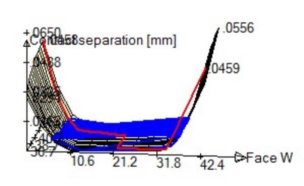
21 Figure 6: Bevel gear compared to the real manufactured gear with the gear generated using hygear TCA ANALYSIS The Transmission Error (TE) and the actual extent of the Bearing Pattern (BP), unloaded and loaded, are readily accessed in graphic form, as shown below. E, P, G, runout, alignment and shaft angle values may also be changed to see how a gear pair will behave in different operating positions as imposed by manufacturing tolerances or housing deformation under load. In addition, E, P, G, alignment and shaft angle values may be modified in pairs to produce a map of the expected behavior of a given gear pair over, say, a given tolerance range. Shown below is such a grid where E and P are modified in combinations. Obviously, the E-P combinations along the diagonal from top-left to bottom-right are not a problem; however, the E-P combinations along the top-right to bottom-left diagonal are to be avoided. 14
22 LTCA ANALYSIS The load and torque transmitted by neighbouring tooth pairs in mesh can be established through the LTCA optional module. The associated bending and contact stresses, bearing reactions, thermal-ehd oil film thickness, temperature increase and scoring factor can be calculated and assessed in real time to ensure a sound design. The axial and radial positions of meshing gear pairs, their alignment and shaft angle can be modified to analyze worst case conditions, or to automatically produce grid-like projections of the loaded behavior of a gear pair. For example, in the figure below, the E and P values of a gear pair are modified to produce E-P combinations allowing prediction of the Hertz contact stresses as the pinion and gear relative position, because of gearbox deflection, manufacturing tolerances, or else, displaces the contact pattern. This Grid-like output can be applied to several combinations of relative positions for gear pairs under load (LTCA). Support bearings and gearbox housing stiffness can be accounted for in the LTCA such that the TE, BP, contact and fillet stresses are calculated at the actual location under load. CMM, CORRECTIVE MACHINE SETTINGS AND REVERSE ENGINEERING Target files for Coordinate Measurement Machines (CMM) can be defined and outputted in Zeiss Ram/Rfd, Gear Bevel, Hoeffler and Klinglenberg-P formats (other formats can easily be added). When the diameter of the CMM probing sphere is given, the sphere (white ball in the figure below) can be displayed and animated along the target CMM grid to visually 15

23 detect possible interference with the opposite tooth flank, or the toot root, as measurement proceeds. HyGEARS can import any text based CMM output file to calculate Corrective Machine Settings, or to Reverse Engineer existing gearsets. CMM results can also be used to estimate the TCA and LTCA behaviour of a real gear pair, and thus allows the troubleshooting and improvement of problematic gear sets. FEA PRE-PROCESSING AND FINITE STRIPS HyGEARS offers advanced functions such as Finite Element Analysis preprocessing (meshing and load application, left figure below), or the analysis of the gears under load using the integrated Finite Strips (right figure below), a subset of the FEA. 16

24 CONTACT ELEMENT An advanced Contact Element is integrated into HyGEARS to allow the precise evaluation of the contact stresses at any point on the tooth surface. Tooth surface irregularities obtained from CMM measurements can be accounted for in the analysis. UNIVERSAL 5 AXIS CNC MACHINE OUTPUT Any (face milled) spiral-bevel gear design that is targeted for cutting on a conventional generator can be converted to a Universal 5 Axis CnC machine, given the sign convention of the axes on the CnC machine is known. For example, below, a partial output for a Universal 5 Axis CnC machine is given for a spiral-bevel pinion manufactured with cutter tilt. In this output, Q and Roll are respectively the cradle and work-piece roll angles on the conventional generator; the X, Y 17
25 and Z axis are conventional, i.e. X is horizontal and + towards the right when facing the machine, Z is vertical and + upwards, and Y is perpendicular to X and Z and + going into the machine; the B axis supports the turntable, and the C axis is the turntable holding the work piece, and thus provides the roll angle of the work-piece on the CnC machine. STEP OUTPUT HyGEARS can directly export the topography of the pinion and gear teeth to any STEP capable CAD/CAM system. Thus, molds for plastic gears, electrodes for sintered gears, or simply CAD models, can conveniently be obtained using the exact tooth topography. For example, the left figure below shows a spiral-bevel pinion tooth in the HyGEARS display; the topography of this tooth was exported in STEP format to a CAD system, which is displayed in the right figure below. 18
26 CHAPTER IV RESULTS CASE 1 INPUT DATA: Number Of Teeth, Pinion = 17 Number Of Teeth, Gear = 94 Pressure Angle = 20 0 Pitch Diameter, Pinion = 76.5mm Face Width, Gear = 43.09mm Face Width, Pinion = 43.09mm Module = 4.5 OUTPUT FROM HYGEARS General Data Pinion Minor Diameter = Outside Diameter = Diameter Over Ball =
27 Roller-Ball Diameter = Addendum Factor = Dedendum Factor = Fillet Factor = Addendum = Dedendum = Gear Number Of Teeth = 94 Face Width = Inner Diameter = Pitch Diameter = Outside Diameter = Addendum Factor = Dedendum Factor = Fillet Factor = Addendum = Dedendum =
28 Blank Data Pinion Mean Helix Angle (Right) = Mean Helix Angle (Left) = Mean Press Angle (Right) = Mean Press Angle (Left) = Gear Mean Helix Angle (Right) = Mean Helix Angle (Left) = Mean Press Angle (Right) = Mean Press Angle (Left) = Tooth Data Pinion Calculated Tooth Depths (Chordal): Form Depth (Mid-F) = Whole Depth (Mid-F) = Calculated Tooth Depths (Circular): Form Depth (Mid-F) = Whole Depth (Mid-F) =
29 Fillet Mid-Face: Drive Root Diameter = Coast = Drive Form Diameter = Coast = Fillet Radius Pressure Mid-Face: Drive Root Diameter = Coast = Drive Form Diameter = 0.07 Coast = 0.07 Calculated Blank Diameters: Root Diam. (Toe) = Tip Diam. (Toe) = Calculated Chordal Tooth Theo. Finish Thickness = Normal Mean Point = Trans. Mean Point = Tooth Topland (Toe) = Tooth Topland (Heel) =
30 Gear Calculated Tooth Depths (Chordal): Form Depth (Mid-F) = Whole Depth (Mid-F) = Calculated Tooth Depths (Circular): Form Depth (Mid-F) = Whole Depth (Mid-F) = Fillet Mid-Face: Drive Root Diameter = Coast = Drive Form Diameter = Coast = Fillet Radius Pressure Mid-Face: Drive Root Diameter = Coast = Drive Form Diameter = Coast = Calculated Chordal Tooth Thoe. Finish Thickness =
31 Normal Mean Point = Trans. Mean Point = Tooth Topland (Toe) = Tooth Topland (Hoel) = Operating Data Pinion Backlash (Min) = Backlash (Max) = Backlash = Bottom Clearance (Toe) = Bottom Clearance (Heel) = Gear Bottom Clearance (Toe) : Bottom Clearance (Heel) : Pinion Cutter Specifications Left and Right Helix Angle = Cutter Type = Normal Shaper Blade Angle = Blade Edge Radius =
32 Blade Thickness = Addendum = Dedendum = Machine Settings Left and Right X Factor = Generating Pitch Dia. = Roll Rate = Tooth Crowning = Crowning Order = 2 Distance To Edge = Gear Cutter Specifications: Left and Right Helix Angle = Cutter Type = Normal Shaper Blade Angle = Blade Edge Radius = Blade Thickness = Addendum = Dedendum =
33 Machine Settings: X Factor = Generating Pitch Dia. = Roll Rate = Tooth Crowning = Crowning Order = 1 Distance To Edge =
34 27

35 28

36 Using the above values from the HyGears, the FaceGear has been developed in the SolidWorks 2011 and performed Finite Element Analysis using SolidWorks Simulation. The load has been applied on the tip of the tooth at an angle of 20 o. The results are: Meshing of Face Gear teeth 29

37 Stress Intensity results: A load of 1200N of force is applied on the tip of the Face gear 30


38 Displacement results: In the figure above 1:400 scale has been taken to have a clear understanding of the Teeth Deformation 31
39 CASE 2 INPUT DATA: Number Of Teeth, Pinion = 17 Number Of Teeth, Gear = 94 Pressure Angle = 25 0 Pitch Diameter, Pinion = 76.5mm Face Width, Gear = 43.09mm Face Width, Pinion = 43.09mm Module = 4.5 OUTPUT DATA FROM HYGEARS: Pinion Minor Diameter = Pitch Diameter = Out Side Diameter = Diameter Over Ball = Roller-Ball Diameter = Addendum Factor = Dedendum Factor = Fillet Factor = Addendum =
40 Dedendum= Gear Inside Diameter = Pitch Diameter = Out Side Diameter = Addendum Factor = Dedendum Factor = Fillet Factor = Addendum = Dedendum = Blank Data Pinion Mean Helix Angle (Right) = Mean Helix Angle (Left) = Mean Helix Angle (Right) = Mean Press Angle (Left) = Gear Mean Helix Angle (Right) = Mean Helix Angle (Left) = Mean Helix Angle (Right) =
41 Mean Press Angle (Left) = Tooth Data Pinion Calculated Tooth Depths (Chordal): Form Depth (Mid - F) = Whole Depth (Mid - F) = Calculated Tooth Depths (Circular): Form Depth (Mid F) = Whole Depth (Mid F) = Fillet Radius & Mid Face: Drive Root Diameter = Coast = Drive Form Diameter = Coast = Fillet Radius Pressure Angle & Mid Face: Drive Root Diameter = Coast = Drive Form Diameter = 9.47 Coast =
42 Calculated Blank Diameters: Root Diam. (Toe) = Tip Diam. (Toe) = Calculated Chordal Tooth Thickness & Mid Face: Theo. Finish Thickness = Normal Thick. &Mean Point = Trans. Thick. & Mean Point = Tooth Topland (Toe) = Tooth Topland (Heel) = Gear Calculated Tooth Depths (Chordal): Form Depth (Mid - F) = Whole Depth (Mid - F) = Calculated Tooth Depths (Circular): Form Depth (Mid F) = Whole Depth (Mid F) = Fillet Radius & Mid Face: Drive Root Diameter = Coast =
43 Drive Form Diameter = Coast = Fillet Radius Pressure Angle & Mid Face: Drive Root Diameter =72.23 Coast = Drive Form Diameter = Coast =29.60 Calculated Chordal Tooth Thickness & Mid Face: Theo. Finish Thickness = Normal Thick. &Mean Point = Trans. Thick. & Mean Point = Tooth Topland (Toe) = Tooth Topland (Heel) = Operating Data Pinion Backlash (Min) = Backlash (Max) = Backlash (Calc&M.Point) = Bottom Clearence (Toe) = Bottom Clearance (Heel) =
44 Gear Bottom Clearence (Toe) = Bottom Clearance (Heel) = Pinion Cutter Specifications Left and Right Helix Angle = Cutter Type = Normal Shaper Blade Angle = Blade Edge Radius = Blade Thickness = Addendum = Dedendum = Machine Settings X Factor = Generating Pitch Dia. = Roll Rate = Tooth Crowning = Crowning Order = 2 Distance To Edge =
45 Gear Cutter Specifications Left and Right Helix Angle = Cutter Type = Normal Shaper Blade Angle = Blade Edge Radius = Blade Thickness = Addendum = Dedendum = Machine Settings X Factor = Generating Pitch Dia. = Roll Rate = Tooth Crowning = Crowning Order = 1 Distance To Edge =

46 39


47 40
48 Using the above values from the HyGears, the FaceGear has been developed in the SolidWorks and performed Finite Element Analysis using SolidWorks Simulation. The load has been applied on the tip of the tooth at an angle of 25 o. The results are: After Meshing: 41

49 A load of 1200N of force is applied on the tip of the Face gear 42


50 Displacement Results: In the figure above 1:400 scale has been taken to have a clear understanding of the Teeth Deformation 43
51 CHAPTER V CONCLUSION AND FUTURE SCOPE 5.1 Conclusion 1. Finite Element method can be successfully used to predict bending stress of a typical Face Gear set 2. The percentage error between AGMA formula and from solidworks for an involute spur gear about 7.4% 3. The geometry can be generated with one face(inner face) of a regular involute spur gear and a point edge on the other face(outer face) 4. The bending stress has been obtained from Solidworks Simulation for two different gears of 20 o and 25 o pressure angle. 5. The result of this study can be used to size a face gear set for a given operating condition (transmitted power at a given speed) and the bending stress on the tooth can be determined
52 5.2 Future Scope 1. Contact stress can also determined for the Facegear 2. Experimental validation of the results predicted by AGMA formula and the Finite element analysis presented in this work 3. Because of the high torque and high loads during operation, considerable amounts of heat is also dissipated. So the heat transfer condition can also be considered in the future analysis of the Facegear. 45
53 BIBLIOGRAPHY [1] Y. Davidov, Non-Involute Gears, Mashgis, 1950 (in Russian). [2] F. L. Litvin, Theory of Gearing, Nauka, 1968 (in Russian). [3] S. Beermann and U. Kissling, "Face Gears: Geometry and strength," Gear Technology, pp , Jan/ Feb [4] F. L. Litvin, "Development of gear technology and theory of gearing," NASA Reference Publication 1406, [5] "Cylkro Face Gear," Nov/Dec [Online]. Available: [Accessed July 2011]. [6] D. W. Dudley, Gear handbook. The design, manufacture, and the application of gears, New York: McGraw- Hill, [7] D. Dudley, Handbook of Practical Gear Design, McGraw-Hill, [8] F. L. Litvin, Gear Geometry and Applied Theory, Prentice Hall, [9] F. L. Litvin, "Handbook of Face Gear Drives with a Spur Involute Pinion," NASA Final Contractor Report, [10] L. F. Litvin and A. E. Aleksandra, "Computerized design, generation and simulation of meshing of orthogonal offset face-gear drive with a spur involute pinion with localized bearing contact," Mech. Math. Theory, vol. 33, no. 1/2, pp ,
54 [11] B. Bloomfield, "Design of Face Gears," Mach Des., vol. 19, no. 4, pp , [12] Bloomingfield, "Alignment charts of face gears," in Product Engineering, 1952, p [13] J. Chakraborty and B. S. Bhadoria, "Some studies on Hypoid Face Gears," Mechanism and machine theory, vol. 8, pp , [14] J. Chakraborty and B. S. Bhadoria, "Design of Face Gears," Mechanisms, vol. 6, pp , [15] D. G. Lewicki and R. F. Handschuh, "Evaluation of Carburized and Ground Face Gears," NASA; US ARL, Quebec, [16] C. Zanzi and J. I. Pedrero, "Application od modified geometry of face gear drive," Elsevier, vol. 194, pp , [17] F. V. and S. J., "Face gear deisgn factors," in Gear design and applications, N. P. Chironis, Ed., McGraw-Hill,
Involute Simulation Softwares Inc
 Involute Simulation Softwares Inc. 1995-2016 www.hygears.com 1 Involute Simulation Softwares Inc. 1139 des Laurentides Québec P.Québec Canada G1S-3C2 Web : www.hygears.com Email : HyGEARS@HyGEARS.com The
Analyses Published on Gear Research Laboratory (
 The analyses that can be carried our in IGD are arranged in two main groups: TCA & FEM analyses: Tooth Contact Analysis and Finite Element Modeling GEO-Comp analyses: Comparison of gear geometries Tooth
EXPERIMENTAL VALIDATION OF A COMPUTERIZED TOOL FOR FACE HOBBED GEAR CONTACT AND TENSILE STRESS ANALYSIS
 Proceedings of the ASME 2007 International Design Engineering Technical Conferences & Computers and Information in Engineering Conference IDETC/CIE 2007 September 4-7, 2007, Las Vegas, Nevada, USA DETC2007-35911
[1] involuteσ(spur and Helical Gear Design)
![[1] involuteσ(spur and Helical Gear Design)](/thumbs/82/86018000.jpg "[1] involuteσ(spur and Helical Gear Design)") [1] involuteσ(spur and Helical Gear Design) 1.3 Software Content 1.3.1 Icon Button There are 12 icon buttons: [Dimension], [Tooth Form], [Accuracy], [Strength], [Sliding Graph], [Hertz Stress Graph], [FEM],
[1] involuteσ(spur and Helical Gear Design) 1.3 Software Content 1.3.1 Icon Button There are 12 icon buttons: [Dimension], [Tooth Form], [Accuracy], [Strength], [Sliding Graph], [Hertz Stress Graph], [FEM],
CHAPTER 4 INCREASING SPUR GEAR TOOTH STRENGTH BY PROFILE MODIFICATION
 68 CHAPTER 4 INCREASING SPUR GEAR TOOTH STRENGTH BY PROFILE MODIFICATION 4.1 INTRODUCTION There is a demand for the gears with higher load carrying capacity and increased fatigue life. Researchers in the
DESIGN OF TRI TANGENT FILLET TOOTH OF A HELICAL GEAR AND ITS CONTACT STRESS ANALYSIS
 DESIGN OF TRI TANGENT FILLET TOOTH OF A HELICAL GEAR AND ITS CONTACT STRESS ANALYSIS Kakani Jhansi Rani *1, M Venkaiah *2 M.Tech, Dr.D.Sunil *3 Ph.D, P.G. Scholar, Dept. of Mechanical Engineering, N.E.C,
1332. Contact characteristics of orthogonal face gear with spur involute pinion
 1332. Contact characteristics of orthogonal face gear with spur involute pinion Yangyi Xiao 1, Wankai Shi 2, Jing Luo 3, Liping Zou The State Key Laboratory of Mechanical Transmission, Chongqing University,
CONTACT STRESS ANALYSIS OF MODIFIED HELICAL GEAR USING CATIA AND ANSYS
 CONTACT STRESS ANALYSIS OF MODIFIED HELICAL GEAR USING CATIA AND ANSYS Raghava Krishna Sameer.B *1, V.Srikanth *2 M.Tech(CAD/CAM), Department of Mechanical, From BRIG-IC, Hyderabad, India. Assistant Professor,
Path of contact calculation KISSsoft
 Path of contact calculation KISSsoft 04-2010 KISSsoft AG - +41 55 254 20 50 Uetzikon 4 - +41 55 254 20 51 8634 Hombrechtikon - info@kisssoft.ag Switzerland - www.kisssoft.ag Path of contact calculation
Load Sharing Based Analysis of Helical Gear using Finite Element Analysis Method
 Load Sharing Based Analysis of Helical Gear using Finite Element Analysis Method D.Deepak 1 1 Assistant professor, Mechanical Engineering, United Institute of Technology, Coimbatore, Tamilnadu, India.
Mathematical Model and Surface Deviation of Cylindrical Gears With Curvilinear Shaped Teeth Cut by a Hob Cutter
 Jui-Tang Tseng Graduate Student Chung-Biau Tsay Professor Department of Mechanical Engineering, National Chiao Tung University, Hsinchu, Taiwan 3000, Republic of China Mathematical Model Surface Deviation
CRIVELLIN PROGETTAZIONI
 1 CRIVELLIN PROGETTAZIONI s.r.l Via Euclide. milano 23 2042 Bra (CN) Sito Web : www.crivellin.com E-mail: progettazioni.crivellin@gmail.com User manual programs: GEAR-1 GEAR-1 INTERNI GEAR-1 SINGOLO (Cylindrical
MASTA 9.0 Release Notes
 November 2018 2018 Smart Manufacturing Technology Ltd. Commercial in Confidence Page 1 of 33 MASTA 9.0 Contents and Summary See next section for additional details The 9.0 release of MASTA contains all
GEAR DESIGN SOLUTIONS
 GEAR DESIGN SOLUTIONS Release 5.0 2012 Dontyne_Brochure2012.indd 2 28/08/2012 09:59 Dontyne SyStems Dontyne Systems offers software and services aimed at the optimum production of gear components and their
A New Stress Analysis Method for Hypoid Gear Drives
 Seoul 000 ISITA World Automotive Congress June -5, 000, Seoul, Korea 00080 A New Stress Analysis Method for Hypoid ear Drives Jui S. Chen American Axle & Manufacturing, Inc 965 Technology Dr Rochester
THREE DIMENSIONAL DYNAMIC STRESS ANALYSES FOR A GEAR TEETH USING FINITE ELEMENT METHOD
 THREE DIMENSIONAL DYNAMIC STRESS ANALYSES FOR A GEAR TEETH USING FINITE ELEMENT METHOD Haval Kamal Asker Department of Mechanical Engineering, Faculty of Agriculture and Forestry, Duhok University, Duhok,
TECHNICAL PAPER. Computerized Design of Face Hobbed Hypoid Gears: Tooth Surfaces Generation, Contact Analysis and Stress Calculation
 05FTM05 Computerized Design of Face Hobbed Hypoid Gears: Tooth Surfaces Generation, Contact Analysis and Stress Calculation by: M. Vimercati, Politecnico di Milano and A. Piazza, Centro Ricerche FIAT -
Contact Characteristics of Circular-Arc Curvilinear Tooth Gear Drives
 Yi-Cheng Wu Engineer Mechanical System Research Laboratory, Industrial Technology Research Institute, Hsinchu 31040, Taiwan e-mail: easonwu@gmail.com Kuan-Yu Chen Ph.D. Cidate Department of Mechanical
Comparison of Bending Stress on Circular and Elliptical Profile Fillet of Helical Gear Using
 Comparison of Bending Stress on Circular and Elliptical Profile Fillet of Helical Gear Using AGMA and ANSYS Bhupendra Kumar Sahu 1, Mahesh Dewangan 2 1 PG Scholar, 2 Associate Professor, 12 Department
GEAR DESIGN SOLUTIONS
 GEAR DESIGN SOLUTIONS *NEW FOR V5.3: 5 Axis Simulation with G-Code Search function in Tool Database Force balancing in Hob and Grind Load Analysis and more... RELEASE 5.3 2016 1 Dontyne Offices HQ, Newcastle,
Stress Analysis of Mating Involute Spur Gear Teeth
 Stress Analysis of Mating Involute Spur Gear Teeth Sushil Kumar Tiwari (PG Student) 1 Upendra Kumar Joshi (Associate Professor) 2 1,2 Department of Mechanical Engineering JEC Jabalpur (M.P.) India ABSTRACT
Computer Aided Design of Helical Cutting Tools
 Computer Aided Design of Helical Cutting Tools Ngoc Thiem Vu, Shinn Liang Chang, Jackson Hu, and Tacker Wang Abstract The helical cutting tools have complex geometries. A rack cutter is the most economical
GEAR DESIGN SOLUTIONS
 GEAR DESIGN SOLUTIONS Release 5.0 2013 Dontyne SyStems Dontyne Systems offers software and services aimed at the optimum production of gear components and their use in the transmission industry. Our range
New modeling method of spiral bevel gears with spherical involute based on CATIA
 New modeling method of spiral bevel gears with spherical involute based on CATIA HONG Zhaobin, YANG Zhaojun, ZHANG Xuecheng, WANG Yankun College of Mechanical Science and Engineering, Jilin University,
A Review On Design, Analysis And Manufacturing Of Spiral Bevel Gear
 A Review On Design, Analysis And Manufacturing Of Spiral Bevel Gear 1 R. M. Jadeja, 2 D. M. Chauhan 1 PG Student, School of Engineering, RK University, Rajkot, Gujarat, India. 2 Assistant Professor, School
LOAD SHARING OF SPUR GEARS IN MESH AN ANALYTICAL AND EXPERIMENTAL STUDY
 NATIONAL TECHNICAL UNIVERSITY OF ATHENS (NTUA) Department of Mechanical Engineering Laboratory of Machine Elements LOAD SHARING OF SPUR GEARS IN MESH AN ANALYTICAL AND EXPERIMENTAL STUDY G. K. Sfantos
ww^ m «\Ji Recent Advances in the Analysis of Spiral Bevel Gears Army Research Laboratory Technical Report ARL-TR-1316
 NASA Technical Memorandum 107391 Army Research Laboratory Technical Report ARL-TR-1316 Recent Advances in the Analysis of Spiral Bevel Gears Robert F. Handschuh U.S. Army Research Laboratory Lewis Research
Effect on Strength of Involute Spur Gear by Changing the Fillet Radius Using FEA
 International Journal Of Scientific & Engineering Research Volume 2, Issue 9, September-2011 1 Effect on Strength of Involute Spur Gear by Changing the Fillet Radius Using FEA Ashwini Joshi, Vijay Kumar
IJMH - International Journal of Management and Humanities ISSN:
 EXPERIMENTAL STRESS ANALYSIS SPUR GEAR USING ANSYS SOFTWARE T.VADIVELU 1 (Department of Mechanical Engineering, JNTU KAKINADA, Kodad, India, vadimay28@gmail.com) Abstract Spur Gear is one of the most important
2. How it started: A problem during the drilling of the world longest tunnel in the Swiss alps
 Ulrich Kissling, Dr. mech. eng., KISSsoft AG, Switzerland Application and Improvement of Face Load Factor Determination based on AGMA 927 (Accurate and fast algorithm for load distribution calculation,
Driven by Innovation. March 28th
 Driven by Innovation March 28th 2014 1 Driven by Innovation 1963: Breton was founded by Marcello Toncelli Today 580 people 81,000 square meters of premises of which 40,000 square meters are covered. 2
[Type text] [Type text] [Type text] GearPro Procedure
![[Type text] [Type text] [Type text] GearPro Procedure](/thumbs/77/76062303.jpg "[Type text] [Type text] [Type text] GearPro Procedure") GearPro Procedure Pictured below is the GearPro main screen. In this manual the icons on the top right corner (Chapter 1), far left side (Chapters 2-5), and far right side (Chapters 6&7) will be discussed.
GearPro Procedure Pictured below is the GearPro main screen. In this manual the icons on the top right corner (Chapter 1), far left side (Chapters 2-5), and far right side (Chapters 6&7) will be discussed.
W6/729 0J7. Meshing of a Spiral Bevel Gearset With 3D Finite Element Analysis. Army Research Laboratory Technical Report ARL-TR-1224
 NASA Technical Memorandum 107336 Army Research Laboratory Technical Report ARL-TR-1224 Meshing of a Spiral Bevel Gearset With 3D Finite Element Analysis George D. Bibel University of North Dakota Grand
MASTA: Overview of Recent & New Functionality
 MASTA: Overview of Recent & New Functionality Euan Woolley - Director SMT, CHARTWELL HOUSE, 67-69 HOUNDS GATE, NOTTINGHAM, NG1 6BB tel. +44 (0)115 941 9839 fax. +44 (0)115 958 1583 SMT Software Development
DRAFT for BETA Release
 KISSsoft Release 03/2014 Changes from Release 03/2013 to Release 03/2014 DRAFT for BETA Release KISSsoft AG Rosengartenstrasse 4 8608 Bubikon Switzerland Tel: +41 55 254 20 50 Fax: +41 55 254 20 51 info@kisssoft.ag
Romax Technology European User Forum 2015
 Romax Technology European User Forum 2015 Frank Seibicke Klingelnberg GmbH Paris, September30 th 2015 Frank Seibicke Klingelnberg GmbH Paris, September 30 th 2015 September 2015 Page 3 A New Challenge
TOOTH'S TENSIONS ANALYSIS OF FACE WORM GEARS WITH CYLINDRICAL PINION DEVELOPMENT OF FEA
 Scientific Bulletin of the Petru Maior University of Tirgu Mures Vol. 6 (XXIII), 2009 ISSN 1841-9267 TOOTH'S TENSIONS ANALYSIS OF FACE WORM GEARS WITH CYLINDRICAL PINION DEVELOPMENT OF FEA Gavril Ion ion_gavrila@yahoo.com
Research on Stress Characteristics of Planetary Gear Drive with Small Tooth Number Difference. Xiaoning Feng
 3rd International Conference on Mechanical Engineering and Intelligent Systems (ICMEIS 5) Research on Stress Characteristics of Planetary Gear Drive with Small Tooth Number Difference Xiaoning Feng Mechanical
Effect of Change of Spur Gear Tooth Parameter On Contact stress
 Effect of Change of Spur Gear Tooth Parameter On Contact stress Nikhil B. Abattini 1, M. M. Mirza 2, P. V. Pawar 3 1 Dept. of Mech. Engineering, Rajarambapu Institute of Technology, Sakharale, Islampur,
ENGINEERING MEASUREMENTS ENTERPRISE LTD. TECHNICAL REPORT RESULTS OF DEVIATION MEASUREMENTS AND GEOMETRY OF ROTARY KILN GEOCEMENT PLANT
 GEOSERVEX s.c. Zbigniew i Boleslaw Krystowczyk e-mail: office@geoservex.com.pl http://www.geoservex.com.pl office: ul. Kościuszki /19A 8-9 Bydgoszcz, POLAND tel: (+48) 34 6 fax: (+48) 34 6 EU VAT ID No:
NONCIRCULAR GEAR DESIGN AND GENERATION BY RACK CUTTER
 , TECHNOLOGIES IN MACHINE BUILDING, ISSN 1221-4566, 2011 NONCIRCULAR GEAR DESIGN AND GENERATION BY RACK CUTTER Marius Vasie,LaurenŃia Andrei University Dunărea de Jos of GalaŃi, Romania v_marius_gl@yahoo.com
Calculation of the Combined Torsional Mesh Stiffness of Spur Gears with Two- and Three-Dimensional Parametrical FE Models
 Paper received: 07.12.2010 DOI: 10.5545/sv-jme.2010.248 Paper accepted: 02.08.2011 Calculation of the Combined Torsional Mesh Stiffness of Spur Gears with Two- and Three-Dimensional Parametrical FE Models
RM E Multiple Inspector Rotating simultaneous measurements
 RM E 07 2014 Multiple Inspector Rotating simultaneous measurements General Information The inspection of workpieces is carried out within a continuous rotation of 360. The workpieces are scanned by radially
GENERATION AND TOOTH CONTACT ANALYSIS (TCA) OF HYPOID GEAR DRIVE
 OF HYPOID GEAR DRIVE") Number 3 Volume 18 march 2012 Journal of Engineering GENERATION AND TOOTH CONTACT ANALYSIS (TCA) OF HYPOID GEAR DRIVE Dep. Of Mech. College of Engineering University of Baghdad ABSTRACT ŀ The present work
Number 3 Volume 18 march 2012 Journal of Engineering GENERATION AND TOOTH CONTACT ANALYSIS (TCA) OF HYPOID GEAR DRIVE Dep. Of Mech. College of Engineering University of Baghdad ABSTRACT ŀ The present work
KISSsoft Changelog Version 03/ Service Pack 6
 KISSsoft Changelog Version 03/2017 - Service Pack 6 KISSsoft - 3D geometry (STEP interface) SP 6 - Tooth end chamfer is not correct in 3D model The tooth end chamfer is not modeled correctly in cylindrical
BGA Technical Awareness Seminar 2010
 BGA Technical Awareness Seminar 2010 Modelling Production Techniques for Accurate Gears Dr. Mike Fish Dr. David Palmer Dontyne Systems Limited 2010 2008 Dontyne Systems Limited is a company registered
KISSsoft 03/2016 Instruction 068a
 KISSsoft 03/2016 Instruction 068a Sizing of Topological Modification of Bevel Gears KISSsoft AG Uetzikon 4 8634 Hombrechtikon Switzerland Tel: +41 55 254 20 50 Fax: +41 55 254 20 51 info@kisssoft.ag www.kisssoft.ag
Design and Analysis of Flex Spline with Involute Teeth Profile for Harmonic Drive Mechanism
 Design and Analysis of Flex Spline with Involute Teeth Profile for Harmonic Drive Mechanism Y. S. Hareesh Assistant Professor, Mechanical Engineering Department College of Engineering & Management, Punnapra
Towards Optimum Involute Gear Design by Combining Addendum and Thickness Modifications
 Towards Optimum Involute Gear Design by Combining Addendum and Thickness Modifications Vasilios Spitas and Christos Spitas Abstract Involute gear sets are being produced through a variety of cutting tools
E91 Machine Design: Lab 2
 E91 Machine Design: Lab 2 Analysis of Stresses in Machines with FEA Techniques Julian Leland Swarthmore College, Fall 2011 ABSTRACT In this lab, a 3- ton arbor press was modeled and assembled in Solidworks.
Parametric investigation of the combined effect of Gear parameters on Tangential Force and Dynamic Tooth Load of 40 Ni2 Cr1 Mo 28 Steel Helical Gear
 Research Article International Journal of Current Engineering and Technology E-ISSN 2277 4106, P-ISSN 2347-5161 2014 INPRESSCO, All Rights Reserved Available at http://inpressco.com/category/ijcet Parametric
MACHINES AND MECHANISMS
 MACHINES AND MECHANISMS APPLIED KINEMATIC ANALYSIS Fourth Edition David H. Myszka University of Dayton PEARSON ж rentice Hall Pearson Education International Boston Columbus Indianapolis New York San Francisco
Using three-dimensional CURVIC contact models to predict stress concentration effects in an axisymmetric model
 Boundary Elements XXVII 245 Using three-dimensional CURVIC contact models to predict stress concentration effects in an axisymmetric model J. J. Rencis & S. R. Pisani Department of Mechanical Engineering,
Changes from Release 03/2011 to Release 03/2012
 Changes from Release 03/2011 to 03/2012 Changes from Release 03/2011 to Release 03/2012 General Module General KISSedit Data Base Tool changes / enhancements Menu Project: drag and drop of files between
Fig.2.1 involuteσⅲ(bevel gear design system)
") [2] involuteσⅲ(bevel gear design system) English version Fig.2.1 involuteσⅲ(bevel gear design system) 2.1 Abstract involute Σ i (bevel gear) has functions such as bevel gear dimensions, strength (steel,
[2] involuteσⅲ(bevel gear design system) English version Fig.2.1 involuteσⅲ(bevel gear design system) 2.1 Abstract involute Σ i (bevel gear) has functions such as bevel gear dimensions, strength (steel,
KISSsoft Module List for Release 03/2011
 KISSsoft 3-2011 KISSsoft Module List for Release 03/2011 Kadkraft Systems Pvt. Ltd. # 316, Sector 37-A, Chandigarh www.kadkraft.com New Feature Highlights Generation of 3D gear models using Parasolid Kernel
A new methodology to optimize spiral bevel gear topography
 A new methodology to optimize spiral bevel gear topography Emmanuel Mermoz, Julien Astoul, Marc Sartor, Jean-Marc Linares, Alain Bernard To cite this version: Emmanuel Mermoz, Julien Astoul, Marc Sartor,
RK E Frenco GmbH
 RK E 04 2016 Frenco GmbH General Information Universal rotation measuring instruments are coordinate measuring devices for rotationally symmetric workpieces. The measurement is carried out by means of
CAD-BASED CALCULATION OF CUTTING FORCE COMPONENTS IN GEAR HOBBING
 CAD-BASED CALCULATION OF CUTTING FORCE COMPONENTS IN GEAR HOBBING BY NIKOLAOS TAPOGLOU and ARISTOMENIS ANTONIADIS Abstract. One of the most commonly used gear manufacturing process especially for external
A novel approach to the inspection of gears with a co-ordinate measuring machine - theoretical aspects
 A novel approach to the inspection of gears with a co-ordinate measuring machine - theoretical aspects C.H. Gao, K. Cheng, D.K. Harrison Department of Engineering, Glasgow Caledonian University Cowcaddens
Hypoid Gears with Involute Teeth
 technical Hypoid Gears with Involute Teeth David B. Dooner This paper presents the geometric design of hypoid gears with involute gear teeth. An overview of face cutting techniques prevalent in hypoid
Effect of Change of Spur Gear Tooth Parameter. On Bending Stress by Simulation
 Effect of Change of Spur Gear Tooth Parameter On Bending Stress by Simulation Nikhil B. Abattini 1, M. M. Mirza 2, P. V. Pawar 3 1 Dept. of Mech. Engineering, Rajarambapu Institute of Technology, Sakharale,
CONTACT STATE AND STRESS ANALYSIS IN A KEY JOINT BY FEM
 PERJODICA POLYTECHNICA SER. ME CH. ENG. VOL. 36, NO. 1, PP. -15-60 (1992) CONTACT STATE AND STRESS ANALYSIS IN A KEY JOINT BY FEM K. VARADI and D. M. VERGHESE Institute of Machine Design Technical University,
Stress Analysis of Cross Groove Type Constant Velocity Joint
 TECHNICAL REPORT Stress Analysis of Cross Groove Type Constant Velocity Joint H. SAITO T. MAEDA The driveshaft is the part that transmits the vehicle's engine torque and rotation to the tires, and predicting
Variation Analysis of Involute Spline Tooth Contact
 Brigham Young University BYU ScholarsArchive All Theses and Dissertations 2006-02-22 Variation Analysis of Involute Spline Tooth Contact Brian J. De Caires Brigham Young University - Provo Follow this
Effect of Rim Thickness on Bending Stresses in Low Addendum Large Spur Gears
 Effect of Rim Thickness on Bending Stresses in Low Addendum Large Spur Gears Yesh P. Singh Department of Mechanical Engineering The University of Texas at San Antonio San Antonio, TX 78249-0670 Ravichandra
KISSsoft Changelog Version 03/ Service Pack 4
 KISSsoft Changelog Version 03/2018 - Service Pack 4 KISSsoft - Bearing calculation SP 4 - NEW! : Calculate bearing performance with SKF bearing module In the bearing calculation (W050, classical method)
Profiling of Screw Compressor Rotors by Use of Direct Digital Simulation
 Purdue University Purdue e-pubs International Compressor Engineering Conference School of Mechanical Engineering 2008 Profiling of Screw Compressor Rotors by Use of Direct Digital Simulation Nikola Stosic
ORBIS MODERN ROLLING-ELEMENT BEARING ANALYSIS SOFTWARE
 ORBIS MODERN ROLLING-ELEMENT BEARING ANALYSIS SOFTWARE OVERVIEW Introduction ORBIS is a computer program to solve the nonlinear elastic behavior of rollingelement ball bearings. The model considers each
GEOMETRIC MODELING AND DYNAMIC SIMULATION OF INVOLUTE GEAR BY GENERATING METHOD
 PROCEEDINGS 13th INTERNATIONAL CONFERENCE ON GEOMETRY AND GRAPHICS August 4-8, 2008, Dresden (Germany ISBN: 978-3-86780-042-6 GEOMETRIC MODELING AND DYNAMIC SIMULATION OF INVOLUTE GEAR BY GENERATING METHOD
Cylinders in Vs An optomechanical methodology Yuming Shen Tutorial for Opti521 November, 2006
 Cylinders in Vs An optomechanical methodology Yuming Shen Tutorial for Opti521 November, 2006 Introduction For rotationally symmetric optical components, a convenient optomechanical approach which is usually
The Importance of Integrated Software Solutions in Troubleshooting Gear Whine
 The Importance of Integrated Software Solutions in Troubleshooting Gear Whine Paul Langlois NVH noise, vibration and harshness is a key issue in the design and development of modern transmission and driveline
IPLEMENTATION OF PARAMETRIC CURVES TO THE DESIGN OF TRUE INVOLUTE GEAR PROFILE
 The 4th International Conference Computational Mechanics and Virtual Engineering COMEC 2011 20-22 OCTOBER 2011, Brasov, Romania IPLEMENTATION OF PARAMETRIC CURVES TO THE DESIGN OF TRUE INVOLUTE GEAR PROFILE
RWS E Frenco GmbH
 RWS E 04 2016 Frenco GmbH Wälzprüfung General Information contact ratio > 1 roll conventional with master gear single flank gear roll inspection contact ratio < 1 power gear flank analysing with roll master
Transient EHL Analysis of Helical Gears
 technical Transient EHL Analysis of Helical Gears Dr. Hazim Jamali, Dr. Kayri J. Sharif, Prof. Pwt Evans and Ray W. Snidle This paper describes a transient, elastohydrodynamic lubrication (EHL) model of
International Journal of Science Engineering and Advance Technology, IJSEAT, Vol 2, Issue 12
 Contact Stress Analysis of Helical Gear by Using AGMA and ANSYS S.Sai Anusha 1 P.Satish Reddy 2 P.Bhaskar 3 M Manoj 4 PG Scholar, Assoc. Professor, Asst Professor, Asst Professor Dept of Mechanical Engineering,
GPK for Design and Rating of Industrial Gearboxes
 GPK for Design and Rating of Industrial Gearboxes KISSsys models: Planetary gear package includes KISSsys models for one and two stage epicyclic gearboxes. The models include automatic presizing of gears,
St 50 gearsolutions.com
 50 gearsolutions.com St Layout of the Gear Micro Geometry By Ulrich Kissling A three-step methodology can be a successful approach to optimizing flank line and profile modifications. The last phase in
STRESS CONCENTRATION FREE SPLINE FOR HIGH TORQUE TWIN SCREW POWER TRANSMISSION
 STRESS CONCENTRATION FREE SPLINE FOR HIGH TORQUE TWIN SCREW POWER TRANSMISSION Joe Mattingly, SteerAmerica Inc., Uniontown, OH Dr. Babu Padmanabhan, C.J. Chetan, Steer Engineering Pvt. Ltd., Bangalore,
MODELLING OF SPUR GEAR CONTACT USING A LOCAL ADAPTIVE FINITE ELEMENT MESH
 MODELLING OF SPUR GEAR CONTACT USING A LOCAL ADAPTIVE FINITE ELEMENT MESH J. Lahtivirta 1*, A. Lehtovaara 1 1 Group of Tribology and Machine Elements, Materials Science: Tampere University of Technology
Topology Optimization and Analysis of Crane Hook Model
 RESEARCH ARTICLE Topology Optimization and Analysis of Crane Hook Model Thejomurthy M.C 1, D.S Ramakrishn 2 1 Dept. of Mechanical engineering, CIT, Gubbi, 572216, India 2 Dept. of Mechanical engineering,
Journal of Engineering Science and Technology Review 8 (6) (2015) 1-5 Special Issue on Simulation of Manufacturing Technologies. Conference Article
 (2015) 1-5 Special Issue on Simulation of Manufacturing Technologies. Conference Article") Jestr Journal of Engineering Science and Technology Review 8 () (2015) 1-5 Special Issue on Simulation of Manufacturing Technologies Conference Article JOURNAL OF Engineering Science and Technology Review
Jestr Journal of Engineering Science and Technology Review 8 () (2015) 1-5 Special Issue on Simulation of Manufacturing Technologies Conference Article JOURNAL OF Engineering Science and Technology Review
HOBBING WEAR PREDICTION MODEL BASED ON 3D CHIPS DETERMINATION
 HOBBING WEAR PREDICTION MODEL BASED ON 3D CHIPS DETERMINATION BY TAXIARCHIS BELIS 1 and ARISTOMENIS ANTONIADIS 1 Abstract. Gear hobbing is a machining process widely used in the industry for massive production
CP Racks. Pinions. Table of Contents. Catalog Number of KHK Stock Gears. Pinions S SCP Pinions. Racks K RGCP 5-500
 Table of ontents pecial haracteristics, oints of aution in electing and Using acks & inions... page 0 T Tapered inions. T Tapered acks... page 2. round pur ears... page 4 ()(D) round acks... page 4 pur
Similar Pulley Wheel Description J.E. Akin, Rice University
 Similar Pulley Wheel Description J.E. Akin, Rice University The SolidWorks simulation tutorial on the analysis of an assembly suggested noting another type of boundary condition that is not illustrated
RESEARCHES CONCERNING SHAFTS AND GEARS MILLING PROCESS
 International Journal of Modern Manufacturing Technologies ISSN 2067 3604, Vol. I, No. 1 / 2009 25 RESEARCHES CONCERNING SHAFTS AND GEARS MILLING PROCESS Ciprian Dumitru Ciofu 1 & Teodor Daniel Mindru
MESYS Shaft Calculation
 MESYS Shaft Calculation Introduction This shaft calculation (Version 04/2017, File version 3.0) calculates the deflections, internal forces and the natural frequencies of several shafts connected by boundary
Automated Drill Design Software
 Automated Drill Design Software Athulan Vijayaraghavan March 19, 2006 Abstract This section of the report discusses a tool which can create automated 3D CAD drill models based on geometric as well as manufacturing
DYNAMIC MODELING OF WORKING SECTIONS OF GRASSLAND OVERSOWING MACHINE MSPD-2.5
 DYNAMIC MODELING OF WORKING SECTIONS OF GRASSLAND OVERSOWING MACHINE MSPD-2.5 Florin Loghin, Simion Popescu, Florean Rus Transilvania University of Brasov, Romania loghinflorin@unitbv.ro, simipop@unitbv.ro,
Transactions on Modelling and Simulation vol 20, 1998 WIT Press, ISSN X
 Failure analysis of gears using the boundary element method R.E. Dippery, Jr. & J. Ellis Mechanical Engineering Department, Kettering University, Flint, Michigan USA Abstract Textbooks such as Norton[l],
2: Static analysis of a plate
 2: Static analysis of a plate Topics covered Project description Using SolidWorks Simulation interface Linear static analysis with solid elements Finding reaction forces Controlling discretization errors
Enhancing Productivity of a Roller Stand through Design Optimization using Manufacturing Simulation
 Enhancing Productivity of a Roller Stand through Design Optimization using Manufacturing Simulation B.R. Krishna Tej 1, N.Sasank Sai 1 and S.Deepak kumar* 1 Engineering Design and Research Center (EDRC)
MATHEMATICAL METHOD DESIGN FOR CALCULATION OF THE INITIAL TOOL SURFACE FOR THE SHARPENING OF HOBING WORMS
 MATHEMATICAL METHOD DESIGN FOR CALCULATION OF THE INITIAL TOOL SURFACE FOR THE SHARPENING OF HOBING WORMS ABSTRACT Ing. Aneta Milsimerová University of West Bohemia in Pilsen Faculty of Mechaical Engineering
II. FINITE ELEMENT MODEL OF CYLINDRICAL ROLLER BEARING
 RESEARCH INVENTY: International Journal of Engineering and Science ISSN: 2278-4721, Vol. 1, Issue 1 (Aug 2012), PP 8-13 www.researchinventy.com Study of Interval of Arc Modification Length of Cylindrical
KISSsoft Changelog Version 03/ Service Pack 7
 KISSsoft Changelog Version 03/2015 - Service Pack 7 KISSsoft - Bearing calculation SP 7 - Friction calculation according SKF 2013 - Until now the curve which defines the drag loss factor VM was splited
Dr. Emilia Abadjieva, Assoc. Prof. in Department Scientific Computations
 Mathematical models for analytical synthesis and software 3D realization of spatial motion transformers: Review of past and current research results Dr. Emilia Abadjieva, Assoc. Prof. in Department Scientific
KISSsoft Tutorial: Roller Bearings
 KISSsoft Tutorial 007: Roller Bearings KISSsoft AG - +41 55 254 20 50 Uetzikon 4 - +41 55 254 20 51 8634 Hombrechtikon - info@kisssoft. AG Switzerland - www. KISSsoft. AG KISSsoft Tutorial: Roller Bearings
KISSsoft 03/2013 Tutorial 5
 KISSsoft 03/2013 Tutorial 5 Shaft analysis KISSsoft AG Rosengartenstrasse 4 8608 Bubikon Switzerland Tel: +41 55 254 20 50 Fax: +41 55 254 20 51 info@kisssoft.ag www.kisssoft.ag Contents 1 Starting KISSsoft...
IMECE OPTIMAL DESIGN OF WORM GEAR SYSTEM USING IN CVVL FOR AUTOMOBILES
 Proceedings of ASME 2013 International Mechanical Engineering Congress & Exposition IMECE 2013 November 15-21, 2013, San Diego, CA, USA IMECE2013-63365 OPTIMAL DESIGN OF WORM GEAR SYSTEM USING IN CVVL
ANALYSIS AND OPTIMIZATION OF FLYWHEEL
 Int. J. Mech. Eng. & Rob. Res. 2012 Sushama G Bawane et al., 2012 Research Paper ISSN 2278 0149 www.ijmerr.com Vol. 1, No. 2, July 2012 2012 IJMERR. All Rights Reserved ANALYSIS AND OPTIMIZATION OF FLYWHEEL