A Stereo Machine Vision System for. displacements when it is subjected to elasticplastic
|
|
|
- Brianne Banks
- 5 years ago
- Views:
Transcription
1 A Stereo Machine Vision System for measuring three-dimensional crack-tip displacements when it is subjected to elasticplastic deformation Arash Karpour Supervisor: Associate Professor K.Zarrabi Co-Supervisor: Professor A.Crosky
2 1. Aims The aims of this project is to: design and manufacture a Stereo Machine Vision System (SMVS) to measure a crack tip displacement in x, y and z direction simultaneously. Keep a low cost in manufacturing SMVS while maintain the accuracy within a acceptable margins.
3 2. Background To study complex behaviour of mixed-modes I,II and III a pair of grips have specially been designed. Using a universal Instron machine and these grips a cracked specimen would go under simultaneous in and out-of- plane (mixed-mode I,II and III) displacement. Mechanical displacement measurement sensors such as clip gauge is used to measure the y-displacement and two Linear Variable Displacement Transducers (LVDT) are used to measure the displacement in x and z direction.
4 2. Background Because of the compound geometry of the grips not all of the mechanical sensors are able to physically fit around the crack tip to measure the displacement. This is where the importance of a non-contactable measurement device such as SMVS become evident.
5 Mode I (Tension, Opening) Mode II (In-plane shear, Sliding) Mode III (Out-of-plane shear, Tearing)
6 3. System Set Up - Hardware INSTRON Load Cell Data Acquisition Upper Grip Specimen Lower Grip PC SMVS


7 3. System Set Up - Hardware Universal Instron Machine Upper Clamp Upper Load Shaft Upper Grip Load Nut Data Acquisition Unit Specimen Lower Grip Lower Load Shaft


8 3. System Set Up - Hardware y θ=45 x z =15

9 3. System Set Up - Hardware
10 3. System Set Up - Hardware
11 L 1 3. System Set Up - Hardware Z L1 X L2
12 3. System Set Up - Hardware Y Micro Positioners Z Macro Positioners X Locking Cap Screws
13 3. System Set Up - Hardware The machine vision consists of: 1-Firewire Cameras: Two DMK 21AF04 firewire cameras

14 3. System Set Up - Hardware 2-Image Processing Card: Fireboard-Blue 1394a PCI adapter
15 3. System Set Up - Hardware 3-Micropositioner: Mellet Geriot 5 axis manual. 4-Macroptioner: Lateral and Transversal linear bearings 5- Navitar Zoom Lenses : The Zoom 7000 offers a 6:1 zoom ratio
16 3. System Set Up - Hardware White lights to illuminate the background White background certain White lights illuminating the test specimen Test Specimen Cluster of high intensity red LEDs Studio lights
17 4. Calibration Camera calibration is the process of identifying the camera s optical parameters and its position and orientation with respect to a pattern frame. Intrinsic parameters: focal length, pixel spacing and distortion of lens. Extrinsic parameters: incorporate rotation of cameras, distance between cameras and angle of the cameras.
18 4. Calibration 1. Calculating the homograms for all points in a series of images. A homogram is a matrix of perspective transformation between the checkerboard (i.e., our calibration pattern plane in SMVS) and the camera view plane. 2. Initializing the intrinsic (including distortion) parameters to zero. 3. Finding extrinsic parameters for each image of the pattern. 4. Optimizing by minimizing error of projection points with all parameters.
19 4. Calibration Checkerboard pattern Rotation and Goniometers (tilt) unis Second rotation and tilt unit Translation (x,y,z) unit
20 4. Calibration Assuming a pinhole camera is used, a 3-D point on specimen surface which is defined as {M} = [ X,Y, Z] T, corresponds to a point on the projected image defined as {m} = [ x, y ] T. During the estimation process, 16 frames from randomly selected angles are captured. The homogram relation between {m} and {M} {m} = [A][R]{t}{M}
21 4. Calibration Object Frame Y M X Z Image Frame x y [Rt] Camera Frame y z A x
22 4. Calibration r11 r12 r13 t1 [R] = r r r,{t} = t r31 r32 r 33 t 3 fl γ c [A] 0 f c = R y x 0 0 1
23 4. Calibration Looking at the homography between the model plane {M} and its image we can assume that the model plane is on Z = 0 of the world coordinate system. Assuming Z = 0 sets the world coordinate system for that particular frame on the model plane. Orientation of the coordinate system changes with the angle which the model plane is set to for that shot.
24 4. Calibration i th If column of a rotation matrix [R] is denoted as then, X x X Y y = [A][ r1 r2 r3 t ] = [A][ r1 r2 t ] Y Therefore a model plane {M} and its image {m} is related by homography [H]: Which [H] is: {m} % = H{M} % [ h h h ] = λ A[ r r t] ri
25 4. Calibration λ r r 1 2 Where is an arbitrary scalar. Knowing and are orthonormal (orthogonal vectors with magnitude of 1, then we have, T T 1 h A A h = h A A h = h A A h T T 1 T T T [A] [A] = [B] is called the absolute conic. B B B = = B31 B32 B T 1 [B] [A] [A] B21 B22 B32
26 4. Calibration 1 γ cxγ cyf R f L f L f R f L f R 2 γ γ 1 (cxγ cyf R ) c y = flfr flfr fr flfr fr 2 cxγ cyf R (cxγ cyf R ) c (c x xγ cyf R ) cx flfr flfr fr flfr f R
27 4. Calibration c x 2 ( B11B22 B12 ) λ = f f L ( B B B B ) = B [ B + c ( B B B B )] x B 11 R 2 B11B22 B12 γ = c y = = λ B x = L 2 13 L 11 λb ( ) 2 B12f LfR λ γc B f f λ
28 4. Calibration Epipolar geometry: the point P, the optical centres O and O of the two cameras, and the two images p and p of P all lie in the same plane.
29 X Intrinsic & x Y extrinsic = y Z parameters 4. Calibration Epipolar geometry depends uniquely on the parameters and geometry of the two cameras and not on the geometry of the scene. A matrix called the fundamental matrix, [F], exists, which is the algebraic representation of the epipolar geometry and which therefore relates an epipolar line to the point it has generated T {m }[F]{M} = 0 X Intrinsic & x Y extrinsic = y Z parameters
30 4. Calibration A pair of corresponding points
31 4. Calibration Once we had a corresponding object pair, we could compute the depth (z value) of the detected object. To do that, we could use the following simple formulas (B f ) z object =,d = xl xr (d PS) x PS z image object x object = (B / 2) y object = y image f PS z f object where d is the disparity (difference between x-values in image plane), B the baseline (distance between cameras) and f is the focal length. PS is the size of one pixel
32 Start Frame Capture Frame Capture Parameter Retrieval Intrinsic Parameter Calibration Extrinsic Parameter Calibration Frame Capture Calibrated? Calibrated? Object Location Parameter Storage Parameter Storage Completed? Parameters Exit

33 4. System Set Up - Software

34 4. System Set Up - Software
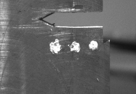
35 5. Results C B A
36 5. Results C B A
37 5. Results C B A
38 Thank you Questions?
55:148 Digital Image Processing Chapter 11 3D Vision, Geometry
 55:148 Digital Image Processing Chapter 11 3D Vision, Geometry Topics: Basics of projective geometry Points and hyperplanes in projective space Homography Estimating homography from point correspondence
CIS 580, Machine Perception, Spring 2015 Homework 1 Due: :59AM
 CIS 580, Machine Perception, Spring 2015 Homework 1 Due: 2015.02.09. 11:59AM Instructions. Submit your answers in PDF form to Canvas. This is an individual assignment. 1 Camera Model, Focal Length and
Camera Model and Calibration
 Camera Model and Calibration Lecture-10 Camera Calibration Determine extrinsic and intrinsic parameters of camera Extrinsic 3D location and orientation of camera Intrinsic Focal length The size of the
CS201 Computer Vision Camera Geometry
 CS201 Computer Vision Camera Geometry John Magee 25 November, 2014 Slides Courtesy of: Diane H. Theriault (deht@bu.edu) Question of the Day: How can we represent the relationships between cameras and the
Machine vision. Summary # 11: Stereo vision and epipolar geometry. u l = λx. v l = λy
 1 Machine vision Summary # 11: Stereo vision and epipolar geometry STEREO VISION The goal of stereo vision is to use two cameras to capture 3D scenes. There are two important problems in stereo vision:
Computer Vision. Coordinates. Prof. Flávio Cardeal DECOM / CEFET- MG.
 Computer Vision Coordinates Prof. Flávio Cardeal DECOM / CEFET- MG cardeal@decom.cefetmg.br Abstract This lecture discusses world coordinates and homogeneous coordinates, as well as provides an overview
3D Sensing and Reconstruction Readings: Ch 12: , Ch 13: ,
 3D Sensing and Reconstruction Readings: Ch 12: 12.5-6, Ch 13: 13.1-3, 13.9.4 Perspective Geometry Camera Model Stereo Triangulation 3D Reconstruction by Space Carving 3D Shape from X means getting 3D coordinates
Epipolar Geometry and the Essential Matrix
 Epipolar Geometry and the Essential Matrix Carlo Tomasi The epipolar geometry of a pair of cameras expresses the fundamental relationship between any two corresponding points in the two image planes, and
DD2423 Image Analysis and Computer Vision IMAGE FORMATION. Computational Vision and Active Perception School of Computer Science and Communication
 DD2423 Image Analysis and Computer Vision IMAGE FORMATION Mårten Björkman Computational Vision and Active Perception School of Computer Science and Communication November 8, 2013 1 Image formation Goal:
Homogeneous Coordinates. Lecture18: Camera Models. Representation of Line and Point in 2D. Cross Product. Overall scaling is NOT important.
 Homogeneous Coordinates Overall scaling is NOT important. CSED44:Introduction to Computer Vision (207F) Lecture8: Camera Models Bohyung Han CSE, POSTECH bhhan@postech.ac.kr (",, ) ()", ), )) ) 0 It is
Camera Model and Calibration. Lecture-12
 Camera Model and Calibration Lecture-12 Camera Calibration Determine extrinsic and intrinsic parameters of camera Extrinsic 3D location and orientation of camera Intrinsic Focal length The size of the
Computer Vision Projective Geometry and Calibration. Pinhole cameras
 Computer Vision Projective Geometry and Calibration Professor Hager http://www.cs.jhu.edu/~hager Jason Corso http://www.cs.jhu.edu/~jcorso. Pinhole cameras Abstract camera model - box with a small hole
Rectification. Dr. Gerhard Roth
 Rectification Dr. Gerhard Roth Problem Definition Given a pair of stereo images, the intrinsic parameters of each camera, and the extrinsic parameters of the system, R, and, compute the image transformation
COSC579: Scene Geometry. Jeremy Bolton, PhD Assistant Teaching Professor
 COSC579: Scene Geometry Jeremy Bolton, PhD Assistant Teaching Professor Overview Linear Algebra Review Homogeneous vs non-homogeneous representations Projections and Transformations Scene Geometry The
3D Geometry and Camera Calibration
 3D Geometry and Camera Calibration 3D Coordinate Systems Right-handed vs. left-handed x x y z z y 2D Coordinate Systems 3D Geometry Basics y axis up vs. y axis down Origin at center vs. corner Will often
Rectification and Distortion Correction
 Rectification and Distortion Correction Hagen Spies March 12, 2003 Computer Vision Laboratory Department of Electrical Engineering Linköping University, Sweden Contents Distortion Correction Rectification
1 Projective Geometry
 CIS8, Machine Perception Review Problem - SPRING 26 Instructions. All coordinate systems are right handed. Projective Geometry Figure : Facade rectification. I took an image of a rectangular object, and
3D Sensing. 3D Shape from X. Perspective Geometry. Camera Model. Camera Calibration. General Stereo Triangulation.
 3D Sensing 3D Shape from X Perspective Geometry Camera Model Camera Calibration General Stereo Triangulation 3D Reconstruction 3D Shape from X shading silhouette texture stereo light striping motion mainly
Computer Vision cmput 428/615
 Computer Vision cmput 428/615 Basic 2D and 3D geometry and Camera models Martin Jagersand The equation of projection Intuitively: How do we develop a consistent mathematical framework for projection calculations?
And. Modal Analysis. Using. VIC-3D-HS, High Speed 3D Digital Image Correlation System. Indian Institute of Technology New Delhi
 Full Field Displacement And Strain Measurement And Modal Analysis Using VIC-3D-HS, High Speed 3D Digital Image Correlation System At Indian Institute of Technology New Delhi VIC-3D, 3D Digital Image Correlation
Rigid Body Motion and Image Formation. Jana Kosecka, CS 482
 Rigid Body Motion and Image Formation Jana Kosecka, CS 482 A free vector is defined by a pair of points : Coordinates of the vector : 1 3D Rotation of Points Euler angles Rotation Matrices in 3D 3 by 3
CSE 252B: Computer Vision II
 CSE 252B: Computer Vision II Lecturer: Serge Belongie Scribe: Sameer Agarwal LECTURE 1 Image Formation 1.1. The geometry of image formation We begin by considering the process of image formation when a
55:148 Digital Image Processing Chapter 11 3D Vision, Geometry
 55:148 Digital Image Processing Chapter 11 3D Vision, Geometry Topics: Basics of projective geometry Points and hyperplanes in projective space Homography Estimating homography from point correspondence
1 (5 max) 2 (10 max) 3 (20 max) 4 (30 max) 5 (10 max) 6 (15 extra max) total (75 max + 15 extra)
 2 (10 max) 3 (20 max) 4 (30 max) 5 (10 max) 6 (15 extra max) total (75 max + 15 extra)") Mierm Exam CS223b Stanford CS223b Computer Vision, Winter 2004 Feb. 18, 2004 Full Name: Email: This exam has 7 pages. Make sure your exam is not missing any sheets, and write your name on every page. The
Mierm Exam CS223b Stanford CS223b Computer Vision, Winter 2004 Feb. 18, 2004 Full Name: Email: This exam has 7 pages. Make sure your exam is not missing any sheets, and write your name on every page. The
Flexible Calibration of a Portable Structured Light System through Surface Plane
 Vol. 34, No. 11 ACTA AUTOMATICA SINICA November, 2008 Flexible Calibration of a Portable Structured Light System through Surface Plane GAO Wei 1 WANG Liang 1 HU Zhan-Yi 1 Abstract For a portable structured
MERGING POINT CLOUDS FROM MULTIPLE KINECTS. Nishant Rai 13th July, 2016 CARIS Lab University of British Columbia
 MERGING POINT CLOUDS FROM MULTIPLE KINECTS Nishant Rai 13th July, 2016 CARIS Lab University of British Columbia Introduction What do we want to do? : Use information (point clouds) from multiple (2+) Kinects
INFO - H Pattern recognition and image analysis. Vision
 INFO - H - 501 Pattern recognition and image analysis Vision Stereovision digital elevation model obstacle avoidance 3D model scanner human machine interface (HMI)... Stereovision image of the same point
Camera Projection Models We will introduce different camera projection models that relate the location of an image point to the coordinates of the
 Camera Projection Models We will introduce different camera projection models that relate the location of an image point to the coordinates of the corresponding 3D points. The projection models include:
Agenda. Rotations. Camera models. Camera calibration. Homographies
 Agenda Rotations Camera models Camera calibration Homographies D Rotations R Y = Z r r r r r r r r r Y Z Think of as change of basis where ri = r(i,:) are orthonormal basis vectors r rotated coordinate
Laser sensors. Transmitter. Receiver. Basilio Bona ROBOTICA 03CFIOR
 Mobile & Service Robotics Sensors for Robotics 3 Laser sensors Rays are transmitted and received coaxially The target is illuminated by collimated rays The receiver measures the time of flight (back and
CV: 3D to 2D mathematics. Perspective transformation; camera calibration; stereo computation; and more
 CV: 3D to 2D mathematics Perspective transformation; camera calibration; stereo computation; and more Roadmap of topics n Review perspective transformation n Camera calibration n Stereo methods n Structured
Camera Calibration. Schedule. Jesus J Caban. Note: You have until next Monday to let me know. ! Today:! Camera calibration
 Camera Calibration Jesus J Caban Schedule! Today:! Camera calibration! Wednesday:! Lecture: Motion & Optical Flow! Monday:! Lecture: Medical Imaging! Final presentations:! Nov 29 th : W. Griffin! Dec 1
Image Formation. Antonino Furnari. Image Processing Lab Dipartimento di Matematica e Informatica Università degli Studi di Catania
 Image Formation Antonino Furnari Image Processing Lab Dipartimento di Matematica e Informatica Università degli Studi di Catania furnari@dmi.unict.it 18/03/2014 Outline Introduction; Geometric Primitives
Single View Geometry. Camera model & Orientation + Position estimation. What am I?
 Single View Geometry Camera model & Orientation + Position estimation What am I? Vanishing points & line http://www.wetcanvas.com/ http://pennpaint.blogspot.com/ http://www.joshuanava.biz/perspective/in-other-words-the-observer-simply-points-in-thesame-direction-as-the-lines-in-order-to-find-their-vanishing-point.html
Single View Geometry. Camera model & Orientation + Position estimation. What am I?
 Single View Geometry Camera model & Orientation + Position estimation What am I? Vanishing point Mapping from 3D to 2D Point & Line Goal: Point Homogeneous coordinates represent coordinates in 2 dimensions
Epipolar geometry contd.
 Epipolar geometry contd. Estimating F 8-point algorithm The fundamental matrix F is defined by x' T Fx = 0 for any pair of matches x and x in two images. Let x=(u,v,1) T and x =(u,v,1) T, each match gives
CHAPTER 3 DISPARITY AND DEPTH MAP COMPUTATION
 CHAPTER 3 DISPARITY AND DEPTH MAP COMPUTATION In this chapter we will discuss the process of disparity computation. It plays an important role in our caricature system because all 3D coordinates of nodes
Camera Models and Image Formation. Srikumar Ramalingam School of Computing University of Utah
 Camera Models and Image Formation Srikumar Ramalingam School of Computing University of Utah srikumar@cs.utah.edu VisualFunHouse.com 3D Street Art Image courtesy: Julian Beaver (VisualFunHouse.com) 3D
Computer Vision I - Algorithms and Applications: Multi-View 3D reconstruction
 Computer Vision I - Algorithms and Applications: Multi-View 3D reconstruction Carsten Rother 09/12/2013 Computer Vision I: Multi-View 3D reconstruction Roadmap this lecture Computer Vision I: Multi-View
calibrated coordinates Linear transformation pixel coordinates
 1 calibrated coordinates Linear transformation pixel coordinates 2 Calibration with a rig Uncalibrated epipolar geometry Ambiguities in image formation Stratified reconstruction Autocalibration with partial
Project 4 Results. Representation. Data. Learning. Zachary, Hung-I, Paul, Emanuel. SIFT and HoG are popular and successful.
 Project 4 Results Representation SIFT and HoG are popular and successful. Data Hugely varying results from hard mining. Learning Non-linear classifier usually better. Zachary, Hung-I, Paul, Emanuel Project
Camera Models and Image Formation. Srikumar Ramalingam School of Computing University of Utah
 Camera Models and Image Formation Srikumar Ramalingam School of Computing University of Utah srikumar@cs.utah.edu Reference Most slides are adapted from the following notes: Some lecture notes on geometric
Stereo. 11/02/2012 CS129, Brown James Hays. Slides by Kristen Grauman
 Stereo 11/02/2012 CS129, Brown James Hays Slides by Kristen Grauman Multiple views Multi-view geometry, matching, invariant features, stereo vision Lowe Hartley and Zisserman Why multiple views? Structure
Computer Vision Projective Geometry and Calibration. Pinhole cameras
 Computer Vision Projective Geometry and Calibration Professor Hager http://www.cs.jhu.edu/~hager Jason Corso http://www.cs.jhu.edu/~jcorso. Pinhole cameras Abstract camera model - box with a small hole
Full Field Displacement and Strain Measurement. On a Charpy Specimen. Using Digital Image Correlation.
 Full Field Displacement and Strain Measurement On a Charpy Specimen Using Digital Image Correlation. Chapter 1: Introduction to Digital Image Correlation D.I.C. The method of 3-D DIGITAL IMAGE CORRELATION
Rectification and Disparity
 Rectification and Disparity Nassir Navab Slides prepared by Christian Unger What is Stereo Vision? Introduction A technique aimed at inferring dense depth measurements efficiently using two cameras. Wide
Minimizing Noise and Bias in 3D DIC. Correlated Solutions, Inc.
 Minimizing Noise and Bias in 3D DIC Correlated Solutions, Inc. Overview Overview of Noise and Bias Digital Image Correlation Background/Tracking Function Minimizing Noise Focus Contrast/Lighting Glare
Agenda. Rotations. Camera calibration. Homography. Ransac
 Agenda Rotations Camera calibration Homography Ransac Geometric Transformations y x Transformation Matrix # DoF Preserves Icon translation rigid (Euclidean) similarity affine projective h I t h R t h sr
Epipolar Geometry Prof. D. Stricker. With slides from A. Zisserman, S. Lazebnik, Seitz
 Epipolar Geometry Prof. D. Stricker With slides from A. Zisserman, S. Lazebnik, Seitz 1 Outline 1. Short introduction: points and lines 2. Two views geometry: Epipolar geometry Relation point/line in two
CSE 252B: Computer Vision II
 CSE 252B: Computer Vision II Lecturer: Serge Belongie Scribe : Martin Stiaszny and Dana Qu LECTURE 0 Camera Calibration 0.. Introduction Just like the mythical frictionless plane, in real life we will
3D Modeling using multiple images Exam January 2008
 3D Modeling using multiple images Exam January 2008 All documents are allowed. Answers should be justified. The different sections below are independant. 1 3D Reconstruction A Robust Approche Consider
Assignment 2 : Projection and Homography
 TECHNISCHE UNIVERSITÄT DRESDEN EINFÜHRUNGSPRAKTIKUM COMPUTER VISION Assignment 2 : Projection and Homography Hassan Abu Alhaija November 7,204 INTRODUCTION In this exercise session we will get a hands-on
Cameras and Stereo CSE 455. Linda Shapiro
 Cameras and Stereo CSE 455 Linda Shapiro 1 Müller-Lyer Illusion http://www.michaelbach.de/ot/sze_muelue/index.html What do you know about perspective projection? Vertical lines? Other lines? 2 Image formation
Image Transformations & Camera Calibration. Mašinska vizija, 2018.
 Image Transformations & Camera Calibration Mašinska vizija, 2018. Image transformations What ve we learnt so far? Example 1 resize and rotate Open warp_affine_template.cpp Perform simple resize
Final Exam Study Guide
 Final Exam Study Guide Exam Window: 28th April, 12:00am EST to 30th April, 11:59pm EST Description As indicated in class the goal of the exam is to encourage you to review the material from the course.
CS4670: Computer Vision
 CS467: Computer Vision Noah Snavely Lecture 13: Projection, Part 2 Perspective study of a vase by Paolo Uccello Szeliski 2.1.3-2.1.6 Reading Announcements Project 2a due Friday, 8:59pm Project 2b out Friday
Depth. Common Classification Tasks. Example: AlexNet. Another Example: Inception. Another Example: Inception. Depth
 Common Classification Tasks Recognition of individual objects/faces Analyze object-specific features (e.g., key points) Train with images from different viewing angles Recognition of object classes Analyze
Computer Vision Lecture 17
 Computer Vision Lecture 17 Epipolar Geometry & Stereo Basics 13.01.2015 Bastian Leibe RWTH Aachen http://www.vision.rwth-aachen.de leibe@vision.rwth-aachen.de Announcements Seminar in the summer semester
Project Title: Welding Machine Monitoring System Phase II. Name of PI: Prof. Kenneth K.M. LAM (EIE) Progress / Achievement: (with photos, if any)
 Progress / Achievement: (with photos, if any)") Address: Hong Kong Polytechnic University, Phase 8, Hung Hom, Kowloon, Hong Kong. Telephone: (852) 3400 8441 Email: cnerc.steel@polyu.edu.hk Website: https://www.polyu.edu.hk/cnerc-steel/ Project Title:
Address: Hong Kong Polytechnic University, Phase 8, Hung Hom, Kowloon, Hong Kong. Telephone: (852) 3400 8441 Email: cnerc.steel@polyu.edu.hk Website: https://www.polyu.edu.hk/cnerc-steel/ Project Title:
Robotics - Projective Geometry and Camera model. Marcello Restelli
 Robotics - Projective Geometr and Camera model Marcello Restelli marcello.restelli@polimi.it Dipartimento di Elettronica, Informazione e Bioingegneria Politecnico di Milano Ma 2013 Inspired from Matteo
CIS 580, Machine Perception, Spring 2016 Homework 2 Due: :59AM
 CIS 580, Machine Perception, Spring 2016 Homework 2 Due: 2015.02.24. 11:59AM Instructions. Submit your answers in PDF form to Canvas. This is an individual assignment. 1 Recover camera orientation By observing
Computer Vision Lecture 17
 Announcements Computer Vision Lecture 17 Epipolar Geometry & Stereo Basics Seminar in the summer semester Current Topics in Computer Vision and Machine Learning Block seminar, presentations in 1 st week
Structure from Motion. Prof. Marco Marcon
 Structure from Motion Prof. Marco Marcon Summing-up 2 Stereo is the most powerful clue for determining the structure of a scene Another important clue is the relative motion between the scene and (mono)
Visual Recognition: Image Formation
 Visual Recognition: Image Formation Raquel Urtasun TTI Chicago Jan 5, 2012 Raquel Urtasun (TTI-C) Visual Recognition Jan 5, 2012 1 / 61 Today s lecture... Fundamentals of image formation You should know
Camera model and multiple view geometry
 Chapter Camera model and multiple view geometry Before discussing how D information can be obtained from images it is important to know how images are formed First the camera model is introduced and then
Computer Vision I - Appearance-based Matching and Projective Geometry
 Computer Vision I - Appearance-based Matching and Projective Geometry Carsten Rother 01/11/2016 Computer Vision I: Image Formation Process Roadmap for next four lectures Computer Vision I: Image Formation
Camera Geometry II. COS 429 Princeton University
 Camera Geometry II COS 429 Princeton University Outline Projective geometry Vanishing points Application: camera calibration Application: single-view metrology Epipolar geometry Application: stereo correspondence
Stereo CSE 576. Ali Farhadi. Several slides from Larry Zitnick and Steve Seitz
 Stereo CSE 576 Ali Farhadi Several slides from Larry Zitnick and Steve Seitz Why do we perceive depth? What do humans use as depth cues? Motion Convergence When watching an object close to us, our eyes
Depth Measurement and 3-D Reconstruction of Multilayered Surfaces by Binocular Stereo Vision with Parallel Axis Symmetry Using Fuzzy
 Depth Measurement and 3-D Reconstruction of Multilayered Surfaces by Binocular Stereo Vision with Parallel Axis Symmetry Using Fuzzy Sharjeel Anwar, Dr. Shoaib, Taosif Iqbal, Mohammad Saqib Mansoor, Zubair
Geometry of image formation
 eometry of image formation Tomáš Svoboda, svoboda@cmp.felk.cvut.cz Czech Technical University in Prague, Center for Machine Perception http://cmp.felk.cvut.cz Last update: November 3, 2008 Talk Outline
Introduction to 3D Imaging: Perceiving 3D from 2D Images
 Introduction to 3D Imaging: Perceiving 3D from 2D Images How can we derive 3D information from one or more 2D images? There have been 2 approaches: 1. intrinsic images: a 2D representation that stores
Reminder: Lecture 20: The Eight-Point Algorithm. Essential/Fundamental Matrix. E/F Matrix Summary. Computing F. Computing F from Point Matches
 Reminder: Lecture 20: The Eight-Point Algorithm F = -0.00310695-0.0025646 2.96584-0.028094-0.00771621 56.3813 13.1905-29.2007-9999.79 Readings T&V 7.3 and 7.4 Essential/Fundamental Matrix E/F Matrix Summary
Stereo Image Rectification for Simple Panoramic Image Generation
 Stereo Image Rectification for Simple Panoramic Image Generation Yun-Suk Kang and Yo-Sung Ho Gwangju Institute of Science and Technology (GIST) 261 Cheomdan-gwagiro, Buk-gu, Gwangju 500-712 Korea Email:{yunsuk,
There are many cues in monocular vision which suggests that vision in stereo starts very early from two similar 2D images. Lets see a few...
 STEREO VISION The slides are from several sources through James Hays (Brown); Srinivasa Narasimhan (CMU); Silvio Savarese (U. of Michigan); Bill Freeman and Antonio Torralba (MIT), including their own
CS223b Midterm Exam, Computer Vision. Monday February 25th, Winter 2008, Prof. Jana Kosecka
 CS223b Midterm Exam, Computer Vision Monday February 25th, Winter 2008, Prof. Jana Kosecka Your name email This exam is 8 pages long including cover page. Make sure your exam is not missing any pages.
Computer Vision Project-1
 University of Utah, School Of Computing Computer Vision Project- Singla, Sumedha sumedha.singla@utah.edu (00877456 February, 205 Theoretical Problems. Pinhole Camera (a A straight line in the world space
ECE 470: Homework 5. Due Tuesday, October 27 in Seth Hutchinson. Luke A. Wendt
 ECE 47: Homework 5 Due Tuesday, October 7 in class @:3pm Seth Hutchinson Luke A Wendt ECE 47 : Homework 5 Consider a camera with focal length λ = Suppose the optical axis of the camera is aligned with
Outline. ETN-FPI Training School on Plenoptic Sensing
 Outline Introduction Part I: Basics of Mathematical Optimization Linear Least Squares Nonlinear Optimization Part II: Basics of Computer Vision Camera Model Multi-Camera Model Multi-Camera Calibration
CS6670: Computer Vision
 CS6670: Computer Vision Noah Snavely Lecture 5: Projection Reading: Szeliski 2.1 Projection Reading: Szeliski 2.1 Projection Müller Lyer Illusion http://www.michaelbach.de/ot/sze_muelue/index.html Modeling
Multiple View Geometry
 Multiple View Geometry CS 6320, Spring 2013 Guest Lecture Marcel Prastawa adapted from Pollefeys, Shah, and Zisserman Single view computer vision Projective actions of cameras Camera callibration Photometric
MAPI Computer Vision. Multiple View Geometry
 MAPI Computer Vision Multiple View Geometry Geometry o Multiple Views 2- and 3- view geometry p p Kpˆ [ K R t]p Geometry o Multiple Views 2- and 3- view geometry Epipolar Geometry The epipolar geometry
Vision Review: Image Formation. Course web page:
 Vision Review: Image Formation Course web page: www.cis.udel.edu/~cer/arv September 10, 2002 Announcements Lecture on Thursday will be about Matlab; next Tuesday will be Image Processing The dates some
Image Rectification (Stereo) (New book: 7.2.1, old book: 11.1)
 (New book: 7.2.1, old book: 11.1)") Image Rectification (Stereo) (New book: 7.2.1, old book: 11.1) Guido Gerig CS 6320 Spring 2013 Credits: Prof. Mubarak Shah, Course notes modified from: http://www.cs.ucf.edu/courses/cap6411/cap5415/, Lecture
Image Rectification (Stereo) (New book: 7.2.1, old book: 11.1) Guido Gerig CS 6320 Spring 2013 Credits: Prof. Mubarak Shah, Course notes modified from: http://www.cs.ucf.edu/courses/cap6411/cap5415/, Lecture
Recap: Features and filters. Recap: Grouping & fitting. Now: Multiple views 10/29/2008. Epipolar geometry & stereo vision. Why multiple views?
 Recap: Features and filters Epipolar geometry & stereo vision Tuesday, Oct 21 Kristen Grauman UT-Austin Transforming and describing images; textures, colors, edges Recap: Grouping & fitting Now: Multiple
An Embedded Calibration Stereovision System
 2012 Intelligent Vehicles Symposium Alcalá de Henares, Spain, June 3-7, 2012 An Embedded Stereovision System JIA Yunde and QIN Xiameng Abstract This paper describes an embedded calibration stereovision
Feature descriptors and matching
 Feature descriptors and matching Detections at multiple scales Invariance of MOPS Intensity Scale Rotation Color and Lighting Out-of-plane rotation Out-of-plane rotation Better representation than color:
Introduction to Computer Vision
 Introduction to Computer Vision Michael J. Black Nov 2009 Perspective projection and affine motion Goals Today Perspective projection 3D motion Wed Projects Friday Regularization and robust statistics
Lecture 9: Epipolar Geometry
 Lecture 9: Epipolar Geometry Professor Fei Fei Li Stanford Vision Lab 1 What we will learn today? Why is stereo useful? Epipolar constraints Essential and fundamental matrix Estimating F (Problem Set 2
Projective Geometry and Camera Models
 Projective Geometry and Camera Models Computer Vision CS 43 Brown James Hays Slides from Derek Hoiem, Alexei Efros, Steve Seitz, and David Forsyth Administrative Stuff My Office hours, CIT 375 Monday and
Computer Vision I - Appearance-based Matching and Projective Geometry
 Computer Vision I - Appearance-based Matching and Projective Geometry Carsten Rother 05/11/2015 Computer Vision I: Image Formation Process Roadmap for next four lectures Computer Vision I: Image Formation
Pin Hole Cameras & Warp Functions
 Pin Hole Cameras & Warp Functions Instructor - Simon Lucey 16-423 - Designing Computer Vision Apps Today Pinhole Camera. Homogenous Coordinates. Planar Warp Functions. Motivation Taken from: http://img.gawkerassets.com/img/18w7i1umpzoa9jpg/original.jpg
Geometric camera models and calibration
 Geometric camera models and calibration http://graphics.cs.cmu.edu/courses/15-463 15-463, 15-663, 15-862 Computational Photography Fall 2018, Lecture 13 Course announcements Homework 3 is out. - Due October
Early Fundamentals of Coordinate Changes and Rotation Matrices for 3D Computer Vision
 Early Fundamentals of Coordinate Changes and Rotation Matrices for 3D Computer Vision Ricardo Fabbri Benjamin B. Kimia Brown University, Division of Engineering, Providence RI 02912, USA Based the first
Fundamentals of Stereo Vision Michael Bleyer LVA Stereo Vision
 Fundamentals of Stereo Vision Michael Bleyer LVA Stereo Vision What Happened Last Time? Human 3D perception (3D cinema) Computational stereo Intuitive explanation of what is meant by disparity Stereo matching
Specifying Complex Scenes
 Transformations Specifying Complex Scenes (x,y,z) (r x,r y,r z ) 2 (,,) Specifying Complex Scenes Absolute position is not very natural Need a way to describe relative relationship: The lego is on top
Archeoviz: Improving the Camera Calibration Process. Jonathan Goulet Advisor: Dr. Kostas Daniilidis
 Archeoviz: Improving the Camera Calibration Process Jonathan Goulet Advisor: Dr. Kostas Daniilidis Problem Project Description Complete 3-D reconstruction of site in Tiwanaku, Bolivia Program for archeologists
CS5670: Computer Vision
 CS5670: Computer Vision Noah Snavely, Zhengqi Li Stereo Single image stereogram, by Niklas Een Mark Twain at Pool Table", no date, UCR Museum of Photography Stereo Given two images from different viewpoints
LUMS Mine Detector Project
 LUMS Mine Detector Project Using visual information to control a robot (Hutchinson et al. 1996). Vision may or may not be used in the feedback loop. Visual (image based) features such as points, lines
Stereo and Epipolar geometry
 Previously Image Primitives (feature points, lines, contours) Today: Stereo and Epipolar geometry How to match primitives between two (multiple) views) Goals: 3D reconstruction, recognition Jana Kosecka
Unit 3 Multiple View Geometry
 Unit 3 Multiple View Geometry Relations between images of a scene Recovering the cameras Recovering the scene structure http://www.robots.ox.ac.uk/~vgg/hzbook/hzbook1.html 3D structure from images Recover