Minimizing Noise and Bias in 3D DIC. Correlated Solutions, Inc.
|
|
|
- Linda McCarthy
- 5 years ago
- Views:
Transcription

1 Minimizing Noise and Bias in 3D DIC Correlated Solutions, Inc.
2 Overview Overview of Noise and Bias Digital Image Correlation Background/Tracking Function Minimizing Noise Focus Contrast/Lighting Glare F-stop Stereo-Angle/Lens selection Good speckle pattern Eliminating Bias Eliminating aliasing Eliminating contaminations/dust Using a our Distortion Correction module for instances of non-parametric distortions, such as the stereomicroscope.
3 Overview of Noise and Bias Noise: random, zero-mean deviations from the correct result Bias: systematic deviations from the correct result Noise and bias are present for location (inplane, out-of-plane), displacement, and strain Noise is unavoidable, but can be minimized with careful setup Bias can be reduced or eliminated with proper setup and parameters
4 Overview of Noise Minimizing Noise: Accuracy can be very variable. Some amount of noise will always be present, but it is possible to minimize noise by paying attention to the following set-up parameters: Focus Contrast/Lighting Glare F-stop Stereo-Angle/Lens selection Once we have the proper set-up, speckle pattern quality is the most important factor for minimizing noise
5 Overview of Bias Eliminating Bias: Eliminating aliasing Eliminating contaminations/dust Using a our Distortion Correction module for instances of non-parametric distortions, such as the stereo-microscope.
6 DIC background To understand noise and accuracy is presented in DIC, it s essential to understand how we track the specimen We track the specimen by assigning subsets throughout the area of interest that contain unique speckle information. We track where these subsets move by checking for possible matches at several locations and use a similarity score (correlation function) to grade them. The march is where the error function is minimized. Classic correlation function: sum of squared differences (SSD) of the pixel values (smaller values = better similarity) Pixel coord., reference image C n/ 2 * ( x, y, u, v) ( I( x i, y j) I ( x u i, y v j i, j n/ 2 Pixel value at (x+i; y+j) Pixel value at (x+u+i; y+v+j) )) 2 Image before motion Image after motion Displacement (disparity) Correlation function n: subset size (9 in our example)
7 Principle Example White pixels are gray level 100 Black pixels are gray level 0 An image is a matrix of natural integers Image, in memory Image, on screen
8 Principle Example The specimen moves such that its image moves 1 pixel up and right Image after motion, in memory Image after motion, on screen
9 Principle Example: subset at (x;y)=(5;5), displacement candidate (u;v)=(-2;-2) C 2 * ( 5,5, 2, 2) ( I(5 i,6 j) I (5 2 i,5 2 j i, j 2 )) (100 0) (0 0) (0 0) (0 0) (100 0) (0 100) (0 100) (0 100) (0 100) (0 0) (0 100) (0 100) (0 100) (0 100) (0 0) (0 100) (0 100) (0 100) (0 100) (0 0) ( ) (0 100) (0 100) (0 100) (100 0) 18, (x;y)=(5;5) Image before motion Image after motion (u;v)=(-2;-2)
10 Principle Example: subset at (x;y)=(5;5), displacement candidate (u;v)=(1;1) C( 5,5,1,1) 0 Better correlation score than candidate (u;v)=(-2;-2) [18,000] Indeed it is the smallest score achieveable (perfect match) (x;y)=(5;5) Image before motion Image after motion (u;v)=(1;1)
11 Noise Reduction How do we reduce displacement noise? Var Reduce camera noise Limited options! ( G / x) Increase subset size Loss of spatial resolution Optimize speckle pattern and test setup This is our best and most important option


12 Iteratively finding the match Reference Deformed

13 Shape of error curve We optimize for U, V, strain, and rotation Let us consider the 1D case U only Error U-position

14 Shape of error curve Typical pattern Resulting graph 2.50E+06 Best match 2.00E E E E E
15 Noise in error curve Effect of noise Noise pushes our best match away from 0! Pixel noise
16 Effects of noise Noise normally cannot be controlled We must increase the signal Steeper drop = better confidence
17 What do we want in a pattern? The local minimum should be deep The minimum should be narrow


18 How do we make the bowl deep? Good contrast Good speckle size


19 How do we make the bowl narrow? Sharp edges Good focus Proper F-stop
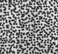
20 Great pattern example
21 Great pattern example Sharpie marker on white paint Bright whites Dark blacks Hard edges Consistent speckle size
22 High-contrast printed pattern
23 High-contrast printed pattern Laser printer CSI target generator Good contrast Consistent size
24 A typical painted pattern

25 A typical painted pattern Inconsistent size No bright white areas Soft edges

26 Effect of reduced contrast
27 Other considerations Focus Brightness Glare F-stop

28 Effect of reduced focus

29 Aperture too small

30 Effect of low light

31 Effect of too much light

32 Effect of Aliasing Aliasing occurs when a signal isn t sampled frequently enough to represent it. Aliasing in a 1D signal:

33 Effect of aliasing Aliasing occurs when the scene contains high-frequency content that cannot be represented by the pixel resolution of the image
34 Effect of aliasing Aliasing is dangerous because it does not always appear in the sigma value We can sometimes see aliasing in the result This is both a bias and an accuracy problem even when not apparent!

35 Effect of aliasing Overly fine pattern

36 Effect of aliasing Showing translation
37 Displacement error from aliasing We calculate the actual displacement vs. the local measured displacement The error is plotted vs. position
38 Displacement error from aliasing The error varies with the pixel position This causes the moiré effect seen before 1pix

39 Strain error from aliasing This can cause very serious strain errors! Waves of compressive strain and tensile strain cause ripples

40 Noise and Bias Due to Aliasing Low fill factors can exacerbate the aliasing issue for a given pattern

41 Bias Due to Aliasing An example of an extremely aliased image due to dithering from a laser printer

42 Noise and Bias Due to Aliasing An example of an extremely aliased image due to dithering from a laser printer


43 Noise and Bias Due to Aliasing
44 Noise and Bias Due to Aliasing Aliased shape

45 Noise and Bias Due to Aliasing With low-pass filtering of image

46 Effects of Aliasing Greatly reduces aliasing - at the expense of actual accuracy
47 Effects of Aliasing Use of low pass filter can help
48 Noise and Bias Due to Aliasing Aliasing can cause severe biases and noise in displacement and strain Best to avoid in the first place bigger patterns or more magnification Can be mitigated Low-pass image filter This comes at the expense of resolution Higher order interpolation

49 A better pattern Showing translation
50 A better pattern Stronger pattern aliasing still visible (low quality camera) but much weaker
51 Mixed sizes - synthetic
52 Mixed sizes - real

53 Speckle Pattern Conclusions Why is this important?
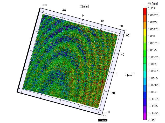
54 Conclusions Z-accuracy
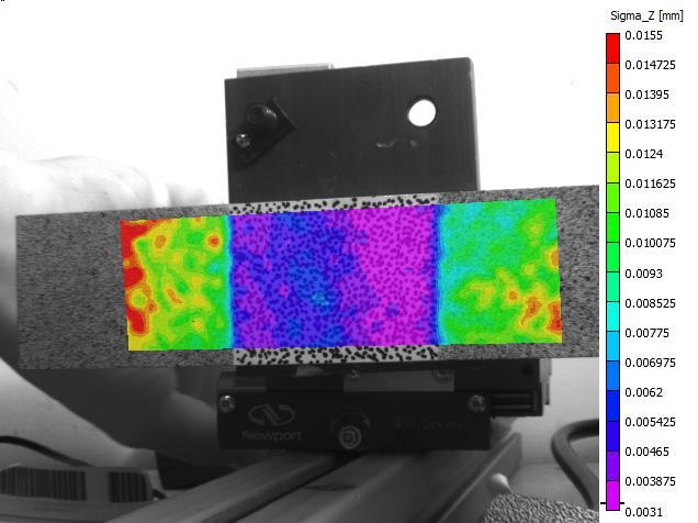
55 Speckle Pattern Conclusions False strain (300uε vs 1300uε)

56 Speckle Pattern Conclusions Shape accuracy
57 Confidence Margins in 3D 3D image correlation contains another important step We want to minimize our Sigma_X/Y/Z This will minimize our strain noise Two components Low pixel sigma Proper test setup
58 Confidence Margins in 3D Camera pinhole point
59 Confidence Margins in 3D Optical axis Camera pinhole point
60 Confidence Margins in 3D Optical axis Sensor plane Camera pinhole point
61 Confidence Margins in 3D Optical axis Focal length Sensor plane Camera pinhole point
62 Confidence Margins in 3D
63 Confidence Margins in 3D Stereo system
64 Confidence Margins in 3D Triangulate point located on optical axis of each camera
65 Confidence Margins in 3D Add noise to 2D image points: This is the noise we have discussed so far in this presentation
66 Confidence Margins in 3D Add noise to 2D image points
67 Confidence Margins in 3D Triangulate modified 3D point
68 Confidence Margins in 3D Measure deviation from noise-free location
69 Confidence Margins in 3D By taking the set of all possible points, we generate a 3D volume in space. The volume has a height (Sigma_Y), a width (Sigma_X), and a depth (Sigma_Z)
70 Confidence Margins in 3D How to minimize the error volume? Minimize noise Proper setup Magnitude of noise Proper setup
71 Effects of setup Short focal length; small angle
72 Effects of setup Short focal length; large angle

73 Effects of setup Long focal length; large angle
74 Minimizing Bias & Noise Noise in displacement and strain is strongly dependent on stereo angle

75 Minimizing Bias & Noise Noise is lowest near the optical axis


76 Bias Due to Contaminations Contamination can cause severe biases in displacement (u shown): This bias will have a strong effect on calculated strains (exx shown):
77 Bias Due to Contaminations Contaminations (e.g., dust on sensor) cause large localized bias in displacement estimates Typically, a large erroneous strain concentration results Not possible to mitigate through processing techniques Always check before taking measurements
78 Bias Due to Poor Calibration A low calibration score is indicative of a good calibration IF we have enough information in the calibration images Large grid that fills up entire image Very large grid tilts (tilt it until it starts to go out of focus) calibration image sets If using short focal length lenses (8mm, 12mm), you might need to change the distortion order to 2 or 3 in the distortion window. In high magnification applications, you might need to select High Mag in the calibration window.
79 Bias Due to Poor Calibration Distortion order for short lenses Calibrate at distortion order 1. Look at your kappa 1 (a lens distortion parameter) in your calibration results. Calibrate at distortion order 2. You ll have a kappa 2 now, but if your kappa 1 is the same as what you got for a distortion order of 1, then the distortion order of 1 was OK. If the kappa 1 changed, then repeat for an order of 3 and see if kappa 2 changed. Once you figure out the distortion order, you can use that that order anytime you use that camera-lens combination
80 Bias Due to Poor Calibration High Magnification For high magnification instances you might see very large calibration errors. This is because the limited depth of field doesn t allow us to tilt the grid enough in order to extract the camera sensor positions. Check your center x, center y for each camera in your calibration results The centers should be ROUGHLY the centers of the sensors (i.e. for 5MP cameras that are 2448x2048 pixels, you should see centers of 1224,1024) If centers are WAY off (by more than 50%; maybe even negative), select high mag This will force the centers to the center of the sensor (1224x1024 in this case). Only use the high mag option when completely necessary because it forces the software to make some assumptions that we d rather extract from the calibration image. High mag is not an option for the stereo microscope module; we use a different calibration method (see next slides)
81 Stereo Microscope For simple lenses the calibration error is typically not a concern when using proper calibration techniques For complex optics, such as the stereo microscope, parametric distortion models are typically not sufficient and severe bias results For accurate measurements using stereo microscopes (or SEMs), a non-parametric distortion calibration technique is required DIC can be used to calibrate such distortions using a simple motion constraint scheme


82 Stereo Microscope No distortion correction Setup: optical stereo-microscope True X and Y-distortion fields (computed by inverse mapping) Distortion corrected Measured principal strain (rigid-body motion)

83 Stereo Microscope Uncorrected shape for a flat plate Corrected shape for a flat plate

84 Stereo Microscope Uncorrected strain for rigid motion

85 Bias Elimination Corrected strain for rigid motion
86 Conclusions With proper set-up, we can eliminate bias and minimize noise. Front-end reductions Proper test setup (focal length, stereo angle, clean lens/sensor, good lighting, correct F-stop, well focused, no blur, no glare) Good speckle pattern (consistent speckle pattern, 50% coverage, good contrast, sharp speckle edges) Good calibration (good tilt in calibration images, select high magnification or distortion order if necessary) Back-end reductions Correct subset sizes Low-pass filtering, if necessary Distortion correction for stereo microscope applications
Vic-3d Educational System Testing Guide
 Vic-3d Educational System Testing Guide Introduction Completing a test with the Vic-3D Educational System is streamlined to make the process as straight forward as possible. This manual explains the procedure
Full Field Displacement and Strain Measurement. On a Charpy Specimen. Using Digital Image Correlation.
 Full Field Displacement and Strain Measurement On a Charpy Specimen Using Digital Image Correlation. Chapter 1: Introduction to Digital Image Correlation D.I.C. The method of 3-D DIGITAL IMAGE CORRELATION
Digital Image Correlation Compared to Strain Gauge
 Digital Image Correlation Compared to Strain Gauge Abstract: This report presents the test results from a stereo digital image correlation system, in which two samples were pulled on a tensile test machine.
And. Modal Analysis. Using. VIC-3D-HS, High Speed 3D Digital Image Correlation System. Indian Institute of Technology New Delhi
 Full Field Displacement And Strain Measurement And Modal Analysis Using VIC-3D-HS, High Speed 3D Digital Image Correlation System At Indian Institute of Technology New Delhi VIC-3D, 3D Digital Image Correlation
Distributed Ray Tracing
 CT5510: Computer Graphics Distributed Ray Tracing BOCHANG MOON Distributed Ray Tracing Motivation The classical ray tracing produces very clean images (look fake) Perfect focus Perfect reflections Sharp
Digital Volume Correlation for Materials Characterization
 19 th World Conference on Non-Destructive Testing 2016 Digital Volume Correlation for Materials Characterization Enrico QUINTANA, Phillip REU, Edward JIMENEZ, Kyle THOMPSON, Sharlotte KRAMER Sandia National
1/12/2009. Image Elements (Pixels) Image Elements (Pixels) Digital Image. Digital Image =...
 Image Elements (Pixels) Digital Image. Digital Image =...") PAM3012 Digital Image Processing for Radiographers Image Sampling & Quantization In this lecture Definitions of Spatial l & Gray-level l resolution Perceived Image Quality & Resolution Aliasing & Moire
PAM3012 Digital Image Processing for Radiographers Image Sampling & Quantization In this lecture Definitions of Spatial l & Gray-level l resolution Perceived Image Quality & Resolution Aliasing & Moire
EE795: Computer Vision and Intelligent Systems
 EE795: Computer Vision and Intelligent Systems Spring 2012 TTh 17:30-18:45 FDH 204 Lecture 14 130307 http://www.ee.unlv.edu/~b1morris/ecg795/ 2 Outline Review Stereo Dense Motion Estimation Translational
12X Zoom. Incredible 12X (0.58-7X) magnification for inspection of a wider range of parts.
 magnification for inspection of a wider range of parts.") Incredible 12X (0.58-7X) magnification for inspection of a wider range of parts. Telecentric attachment gives you the world s first parfocal telecentric zoom lens with field coverage up to 50 mm. Increased
Incredible 12X (0.58-7X) magnification for inspection of a wider range of parts. Telecentric attachment gives you the world s first parfocal telecentric zoom lens with field coverage up to 50 mm. Increased
SEM Drift Correction. Procedure Guide
 SEM Drift Correction Procedure Guide Introduction Vic-2D includes experimental functionality to correct for both drift and geometric distortions that occur in images taken using SEMs. The correction requires
IR Integration with Vic-Snap and Combining IR Data with Vic-3D. Procedure Guide
 IR Integration with Vic-Snap and Combining IR Data with Vic-3D Procedure Guide Introduction This guide lays out the steps for combining 3D DIC data with temperature data from an IR camera. The basic parts
CIS 580, Machine Perception, Spring 2015 Homework 1 Due: :59AM
 CIS 580, Machine Perception, Spring 2015 Homework 1 Due: 2015.02.09. 11:59AM Instructions. Submit your answers in PDF form to Canvas. This is an individual assignment. 1 Camera Model, Focal Length and
Application Note AN-1703 Strain Filter Selection
 Application Note AN-1703 Strain Filter Selection Introduction Strain filters in Vic-2D and Vic-3D are user-defined so that users can select how localized or how averaged the strains will be presented in
Optimized Design of 3D Laser Triangulation Systems
 The Scan Principle of 3D Laser Triangulation Triangulation Geometry Example of Setup Z Y X Target as seen from the Camera Sensor Image of Laser Line The Scan Principle of 3D Laser Triangulation Detektion
Introduction to 3D Machine Vision
 Introduction to 3D Machine Vision 1 Many methods for 3D machine vision Use Triangulation (Geometry) to Determine the Depth of an Object By Different Methods: Single Line Laser Scan Stereo Triangulation
DD2423 Image Analysis and Computer Vision IMAGE FORMATION. Computational Vision and Active Perception School of Computer Science and Communication
 DD2423 Image Analysis and Computer Vision IMAGE FORMATION Mårten Björkman Computational Vision and Active Perception School of Computer Science and Communication November 8, 2013 1 Image formation Goal:
OVERVIEW FILE MENU. The FILE MENU provides the following functions:
 ReferenceManual OVERVIEW The user interface of Vic-3D has many of the familiar control elements found in other applications. The image below illustrates the user interface. The most commonly used functions
An Intuitive Explanation of Fourier Theory
 An Intuitive Explanation of Fourier Theory Steven Lehar slehar@cns.bu.edu Fourier theory is pretty complicated mathematically. But there are some beautifully simple holistic concepts behind Fourier theory
Chapter 3 Image Registration. Chapter 3 Image Registration
 Chapter 3 Image Registration Distributed Algorithms for Introduction (1) Definition: Image Registration Input: 2 images of the same scene but taken from different perspectives Goal: Identify transformation
Ruch (Motion) Rozpoznawanie Obrazów Krzysztof Krawiec Instytut Informatyki, Politechnika Poznańska. Krzysztof Krawiec IDSS
 Rozpoznawanie Obrazów Krzysztof Krawiec Instytut Informatyki, Politechnika Poznańska. Krzysztof Krawiec IDSS") Ruch (Motion) Rozpoznawanie Obrazów Krzysztof Krawiec Instytut Informatyki, Politechnika Poznańska 1 Krzysztof Krawiec IDSS 2 The importance of visual motion Adds entirely new (temporal) dimension to visual
Ruch (Motion) Rozpoznawanie Obrazów Krzysztof Krawiec Instytut Informatyki, Politechnika Poznańska 1 Krzysztof Krawiec IDSS 2 The importance of visual motion Adds entirely new (temporal) dimension to visual
Announcements. Written Assignment 2 out (due March 8) Computer Graphics
 Computer Graphics") Announcements Written Assignment 2 out (due March 8) 1 Advanced Ray Tracing (Recursive) Ray Tracing Antialiasing Motion Blur Distribution Ray Tracing Ray Tracing and Radiosity Assumptions Simple shading
Announcements Written Assignment 2 out (due March 8) 1 Advanced Ray Tracing (Recursive) Ray Tracing Antialiasing Motion Blur Distribution Ray Tracing Ray Tracing and Radiosity Assumptions Simple shading
lecture 10 - depth from blur, binocular stereo
 This lecture carries forward some of the topics from early in the course, namely defocus blur and binocular disparity. The main emphasis here will be on the information these cues carry about depth, rather
EE368 Project: Visual Code Marker Detection
 EE368 Project: Visual Code Marker Detection Kahye Song Group Number: 42 Email: kahye@stanford.edu Abstract A visual marker detection algorithm has been implemented and tested with twelve training images.
Product information. Hi-Tech Electronics Pte Ltd
 Product information Introduction TEMA Motion is the world leading software for advanced motion analysis. Starting with digital image sequences the operator uses TEMA Motion to track objects in images,
ECE-161C Cameras. Nuno Vasconcelos ECE Department, UCSD
 ECE-161C Cameras Nuno Vasconcelos ECE Department, UCSD Image formation all image understanding starts with understanding of image formation: projection of a scene from 3D world into image on 2D plane 2
CS201 Computer Vision Camera Geometry
 CS201 Computer Vision Camera Geometry John Magee 25 November, 2014 Slides Courtesy of: Diane H. Theriault (deht@bu.edu) Question of the Day: How can we represent the relationships between cameras and the
Digital Image Processing COSC 6380/4393
 Digital Image Processing COSC 6380/4393 Lecture 4 Jan. 24 th, 2019 Slides from Dr. Shishir K Shah and Frank (Qingzhong) Liu Digital Image Processing COSC 6380/4393 TA - Office: PGH 231 (Update) Shikha
A Stereo Machine Vision System for. displacements when it is subjected to elasticplastic
 A Stereo Machine Vision System for measuring three-dimensional crack-tip displacements when it is subjected to elasticplastic deformation Arash Karpour Supervisor: Associate Professor K.Zarrabi Co-Supervisor:
Correspondence and Stereopsis. Original notes by W. Correa. Figures from [Forsyth & Ponce] and [Trucco & Verri]
![Correspondence and Stereopsis. Original notes by W. Correa. Figures from [Forsyth & Ponce] and [Trucco & Verri]](/thumbs/80/81283374.jpg "Correspondence and Stereopsis. Original notes by W. Correa. Figures from [Forsyth & Ponce] and [Trucco & Verri]") Correspondence and Stereopsis Original notes by W. Correa. Figures from [Forsyth & Ponce] and [Trucco & Verri] Introduction Disparity: Informally: difference between two pictures Allows us to gain a strong
Correspondence and Stereopsis Original notes by W. Correa. Figures from [Forsyth & Ponce] and [Trucco & Verri] Introduction Disparity: Informally: difference between two pictures Allows us to gain a strong
Chapter 2 - Fundamentals. Comunicação Visual Interactiva
 Chapter - Fundamentals Comunicação Visual Interactiva Structure of the human eye (1) CVI Structure of the human eye () Celular structure of the retina. On the right we can see one cone between two groups
Range Imaging Through Triangulation. Range Imaging Through Triangulation. Range Imaging Through Triangulation. Range Imaging Through Triangulation
 Obviously, this is a very slow process and not suitable for dynamic scenes. To speed things up, we can use a laser that projects a vertical line of light onto the scene. This laser rotates around its vertical
L16. Scan Matching and Image Formation
 EECS568 Mobile Robotics: Methods and Principles Prof. Edwin Olson L16. Scan Matching and Image Formation Scan Matching Before After 2 Scan Matching Before After 2 Map matching has to be fast 14 robots
Sherlock 7 Technical Resource. Laser Tools
 Sherlock 7 Technical Resource DALSA Corp. IPD www.goipd.com 978.670.2002 (U.S.A.) Document Revision: June 27, 2007 Laser Tools Laser Tools used to check the placement of protective wrapping on high-pressure
Applications of Piezo Actuators for Space Instrument Optical Alignment
 Year 4 University of Birmingham Presentation Applications of Piezo Actuators for Space Instrument Optical Alignment Michelle Louise Antonik 520689 Supervisor: Prof. B. Swinyard Outline of Presentation
Accurately measuring 2D position using a composed moiré grid pattern and DTFT
 1 2 3 4 5 6 7 8 9 10 11 12 13 14 15 16 17 18 19 20 21 22 23 24 25 26 27 28 29 30 31 32 33 34 35 36 37 38 39 40 41 42 Accurately measuring 2D position using a composed moiré grid pattern and DTFT S. Van
Stereo vision. Many slides adapted from Steve Seitz
 Stereo vision Many slides adapted from Steve Seitz What is stereo vision? Generic problem formulation: given several images of the same object or scene, compute a representation of its 3D shape What is
Rodenstock Products Photo Optics / Digital Imaging
 Go to: Apo-Sironar digital Apo-Macro-Sironar digital Apo-Sironar digital HR Lenses for Digital Professional Photography Digital photography may be superior to conventional photography if the end-product
Practice Exam Sample Solutions
 CS 675 Computer Vision Instructor: Marc Pomplun Practice Exam Sample Solutions Note that in the actual exam, no calculators, no books, and no notes allowed. Question 1: out of points Question 2: out of
Image Formation I Chapter 1 (Forsyth&Ponce) Cameras
 Cameras") Image Formation I Chapter 1 (Forsyth&Ponce) Cameras Guido Gerig CS 632 Spring 213 cknowledgements: Slides used from Prof. Trevor Darrell, (http://www.eecs.berkeley.edu/~trevor/cs28.html) Some slides modified
Image Formation I Chapter 1 (Forsyth&Ponce) Cameras Guido Gerig CS 632 Spring 213 cknowledgements: Slides used from Prof. Trevor Darrell, (http://www.eecs.berkeley.edu/~trevor/cs28.html) Some slides modified
Final Exam Study Guide
 Final Exam Study Guide Exam Window: 28th April, 12:00am EST to 30th April, 11:59pm EST Description As indicated in class the goal of the exam is to encourage you to review the material from the course.
Points Lines Connected points X-Y Scatter. X-Y Matrix Star Plot Histogram Box Plot. Bar Group Bar Stacked H-Bar Grouped H-Bar Stacked
 Plotting Menu: QCExpert Plotting Module graphs offers various tools for visualization of uni- and multivariate data. Settings and options in different types of graphs allow for modifications and customizations
Digital Image Correlation combined with Electronic Speckle Pattern Interferometery for 3D Deformation Measurement in Small Samples
 Digital Image Correlation combined with Electronic Speckle Pattern Interferometery for 3D Deformation Measurement in Small Samples Phillip L. Reu * and Bruce D. Hansche Sandia National Laboratories, PO
Lecture 16: Computer Vision
 CS4442/9542b: Artificial Intelligence II Prof. Olga Veksler Lecture 16: Computer Vision Motion Slides are from Steve Seitz (UW), David Jacobs (UMD) Outline Motion Estimation Motion Field Optical Flow Field
Image Acquisition Image Digitization Spatial domain Intensity domain Image Characteristics
 Image Acquisition Image Digitization Spatial domain Intensity domain Image Characteristics 1 What is an Image? An image is a projection of a 3D scene into a 2D projection plane. An image can be defined
LEXT 3D Measuring LASER Microscope
 LEXT 3D Measuring LASER Microscope Warning: This instrument may only be operated by those who have been trained by AAF staff and have read and signed the AAF laboratory policies. A) STARTUP 1. Computer
Error assessment in Image Stereo-correlation
 EPJ Web of Conferences 6, 6 31009 (2010) DOI:10.1051/epjconf/20100631009 Owned by the authors, published by EDP Sciences, 2010 Error assessment in Image Stereo-correlation M. Fazzini 1,a, S. Mistou 1 and
Laser sensors. Transmitter. Receiver. Basilio Bona ROBOTICA 03CFIOR
 Mobile & Service Robotics Sensors for Robotics 3 Laser sensors Rays are transmitted and received coaxially The target is illuminated by collimated rays The receiver measures the time of flight (back and
Cameras and Stereo CSE 455. Linda Shapiro
 Cameras and Stereo CSE 455 Linda Shapiro 1 Müller-Lyer Illusion http://www.michaelbach.de/ot/sze_muelue/index.html What do you know about perspective projection? Vertical lines? Other lines? 2 Image formation
Stereo Vision A simple system. Dr. Gerhard Roth Winter 2012
 Stereo Vision A simple system Dr. Gerhard Roth Winter 2012 Stereo Stereo Ability to infer information on the 3-D structure and distance of a scene from two or more images taken from different viewpoints
Depth Estimation with a Plenoptic Camera
 Depth Estimation with a Plenoptic Camera Steven P. Carpenter 1 Auburn University, Auburn, AL, 36849 The plenoptic camera is a tool capable of recording significantly more data concerning a particular image
EE 264: Image Processing and Reconstruction. Image Motion Estimation I. EE 264: Image Processing and Reconstruction. Outline
 1 Image Motion Estimation I 2 Outline 1. Introduction to Motion 2. Why Estimate Motion? 3. Global vs. Local Motion 4. Block Motion Estimation 5. Optical Flow Estimation Basics 6. Optical Flow Estimation
Camera model and multiple view geometry
 Chapter Camera model and multiple view geometry Before discussing how D information can be obtained from images it is important to know how images are formed First the camera model is introduced and then
Stereo imaging ideal geometry
 Stereo imaging ideal geometry (X,Y,Z) Z f (x L,y L ) f (x R,y R ) Optical axes are parallel Optical axes separated by baseline, b. Line connecting lens centers is perpendicular to the optical axis, and
CS 563 Advanced Topics in Computer Graphics Camera Models. by Kevin Kardian
 CS 563 Advanced Topics in Computer Graphics Camera Models by Kevin Kardian Introduction Pinhole camera is insufficient Everything in perfect focus Less realistic Different camera models are possible Create
Chapter 3: Intensity Transformations and Spatial Filtering
 Chapter 3: Intensity Transformations and Spatial Filtering 3.1 Background 3.2 Some basic intensity transformation functions 3.3 Histogram processing 3.4 Fundamentals of spatial filtering 3.5 Smoothing
Kinect Cursor Control EEE178 Dr. Fethi Belkhouche Christopher Harris Danny Nguyen I. INTRODUCTION
 Kinect Cursor Control EEE178 Dr. Fethi Belkhouche Christopher Harris Danny Nguyen Abstract: An XBOX 360 Kinect is used to develop two applications to control the desktop cursor of a Windows computer. Application
Motion. 1 Introduction. 2 Optical Flow. Sohaib A Khan. 2.1 Brightness Constancy Equation
 Motion Sohaib A Khan 1 Introduction So far, we have dealing with single images of a static scene taken by a fixed camera. Here we will deal with sequence of images taken at different time intervals. Motion
Technical Data Sheet. PEAK Measuring Microscope 2054 Series
 PEAK Measuring Microscope 2054 Series Portable Wide Stand Microscope 20x, 40x, 60x, 100x, 150x, 200x, 300x magnification 0.1-0.001 measuring scale Rack & pinion focusing Non-reversed image The 2054 series
The Paper Project Guide to Confocal Imaging at Home & in the Classroom
 The Paper Project Guide to Confocal Imaging at Home & in the Classroom http://lifesciences.asu.edu/paperproject The Paper Project Guide to Confocal Imaging at Home & in the Classroom CJ Kazilek & Dennis
TAGARNO. TAGARNO MEDTECH 320 when quality is paramount
 TAGARNO when quality is paramount 2 when quality is paramount when quality is paramount Image Capture on SD card Non-contact Measurements Display of Magnification Degree Split Screen Function Training
Using the DATAMINE Program
 6 Using the DATAMINE Program 304 Using the DATAMINE Program This chapter serves as a user s manual for the DATAMINE program, which demonstrates the algorithms presented in this book. Each menu selection
Image Formation I Chapter 1 (Forsyth&Ponce) Cameras
 Cameras") Image Formation I Chapter 1 (Forsyth&Ponce) Cameras Guido Gerig CS 632 Spring 215 cknowledgements: Slides used from Prof. Trevor Darrell, (http://www.eecs.berkeley.edu/~trevor/cs28.html) Some slides modified
Image Formation I Chapter 1 (Forsyth&Ponce) Cameras Guido Gerig CS 632 Spring 215 cknowledgements: Slides used from Prof. Trevor Darrell, (http://www.eecs.berkeley.edu/~trevor/cs28.html) Some slides modified
Miniaturized Camera Systems for Microfactories
 Miniaturized Camera Systems for Microfactories Timo Prusi, Petri Rokka, and Reijo Tuokko Tampere University of Technology, Department of Production Engineering, Korkeakoulunkatu 6, 33720 Tampere, Finland
Rigid Body Motion and Image Formation. Jana Kosecka, CS 482
 Rigid Body Motion and Image Formation Jana Kosecka, CS 482 A free vector is defined by a pair of points : Coordinates of the vector : 1 3D Rotation of Points Euler angles Rotation Matrices in 3D 3 by 3
Lecture 16: Computer Vision
 CS442/542b: Artificial ntelligence Prof. Olga Veksler Lecture 16: Computer Vision Motion Slides are from Steve Seitz (UW), David Jacobs (UMD) Outline Motion Estimation Motion Field Optical Flow Field Methods
Identifying and Reading Visual Code Markers
 O. Feinstein, EE368 Digital Image Processing Final Report 1 Identifying and Reading Visual Code Markers Oren Feinstein, Electrical Engineering Department, Stanford University Abstract A visual code marker
3D Sensing. 3D Shape from X. Perspective Geometry. Camera Model. Camera Calibration. General Stereo Triangulation.
 3D Sensing 3D Shape from X Perspective Geometry Camera Model Camera Calibration General Stereo Triangulation 3D Reconstruction 3D Shape from X shading silhouette texture stereo light striping motion mainly
Depth. Common Classification Tasks. Example: AlexNet. Another Example: Inception. Another Example: Inception. Depth
 Common Classification Tasks Recognition of individual objects/faces Analyze object-specific features (e.g., key points) Train with images from different viewing angles Recognition of object classes Analyze
A Low Power, High Throughput, Fully Event-Based Stereo System: Supplementary Documentation
 A Low Power, High Throughput, Fully Event-Based Stereo System: Supplementary Documentation Alexander Andreopoulos, Hirak J. Kashyap, Tapan K. Nayak, Arnon Amir, Myron D. Flickner IBM Research March 25,
Image Formation I Chapter 2 (R. Szelisky)
") Image Formation I Chapter 2 (R. Selisky) Guido Gerig CS 632 Spring 22 cknowledgements: Slides used from Prof. Trevor Darrell, (http://www.eecs.berkeley.edu/~trevor/cs28.html) Some slides modified from
Image Formation I Chapter 2 (R. Selisky) Guido Gerig CS 632 Spring 22 cknowledgements: Slides used from Prof. Trevor Darrell, (http://www.eecs.berkeley.edu/~trevor/cs28.html) Some slides modified from
Geometric camera models and calibration
 Geometric camera models and calibration http://graphics.cs.cmu.edu/courses/15-463 15-463, 15-663, 15-862 Computational Photography Fall 2018, Lecture 13 Course announcements Homework 3 is out. - Due October
Edge and corner detection
 Edge and corner detection Prof. Stricker Doz. G. Bleser Computer Vision: Object and People Tracking Goals Where is the information in an image? How is an object characterized? How can I find measurements
Capturing, Modeling, Rendering 3D Structures
 Computer Vision Approach Capturing, Modeling, Rendering 3D Structures Calculate pixel correspondences and extract geometry Not robust Difficult to acquire illumination effects, e.g. specular highlights
diffraction patterns obtained with convergent electron beams yield more information than patterns obtained with parallel electron beams:
 CBED-Patterns Principle of CBED diffraction patterns obtained with convergent electron beams yield more information than patterns obtained with parallel electron beams: specimen thickness more precise
EXAM SOLUTIONS. Image Processing and Computer Vision Course 2D1421 Monday, 13 th of March 2006,
 School of Computer Science and Communication, KTH Danica Kragic EXAM SOLUTIONS Image Processing and Computer Vision Course 2D1421 Monday, 13 th of March 2006, 14.00 19.00 Grade table 0-25 U 26-35 3 36-45
Lab 5 Microscopy. Introduction. Carrying the Microscope. Depth of Focus. Parts of the Compound Microscope. Magnification
 Lab 5 Microscopy Introduction The microscope is an instrument that contains one or more lenses and is used to view objects that are too small be seen with the unaided eye. A magnifying glass is a simple
% StrainMaster Portable. Full Field Measurement and Characterization of Materials, Components and Structures
 7.72974 % StrainMaster Portable Full Field Measurement and Characterization of Materials, Components and Structures Whole Surface Measurements StrainMaster systems are based around the technique known
ROBUST LINE-BASED CALIBRATION OF LENS DISTORTION FROM A SINGLE VIEW
 ROBUST LINE-BASED CALIBRATION OF LENS DISTORTION FROM A SINGLE VIEW Thorsten Thormählen, Hellward Broszio, Ingolf Wassermann thormae@tnt.uni-hannover.de University of Hannover, Information Technology Laboratory,
Advanced Vision Guided Robotics. David Bruce Engineering Manager FANUC America Corporation
 Advanced Vision Guided Robotics David Bruce Engineering Manager FANUC America Corporation Traditional Vision vs. Vision based Robot Guidance Traditional Machine Vision Determine if a product passes or
Introduction to Computer Vision
 Introduction to Computer Vision Michael J. Black Nov 2009 Perspective projection and affine motion Goals Today Perspective projection 3D motion Wed Projects Friday Regularization and robust statistics
CS 787: Assignment 4, Stereo Vision: Block Matching and Dynamic Programming Due: 12:00noon, Fri. Mar. 30, 2007.
 CS 787: Assignment 4, Stereo Vision: Block Matching and Dynamic Programming Due: 12:00noon, Fri. Mar. 30, 2007. In this assignment you will implement and test some simple stereo algorithms discussed in
EE795: Computer Vision and Intelligent Systems
 EE795: Computer Vision and Intelligent Systems Spring 2012 TTh 17:30-18:45 WRI C225 Lecture 02 130124 http://www.ee.unlv.edu/~b1morris/ecg795/ 2 Outline Basics Image Formation Image Processing 3 Intelligent
Finally: Motion and tracking. Motion 4/20/2011. CS 376 Lecture 24 Motion 1. Video. Uses of motion. Motion parallax. Motion field
 Finally: Motion and tracking Tracking objects, video analysis, low level motion Motion Wed, April 20 Kristen Grauman UT-Austin Many slides adapted from S. Seitz, R. Szeliski, M. Pollefeys, and S. Lazebnik
3D Computer Vision. Depth Cameras. Prof. Didier Stricker. Oliver Wasenmüller
 3D Computer Vision Depth Cameras Prof. Didier Stricker Oliver Wasenmüller Kaiserlautern University http://ags.cs.uni-kl.de/ DFKI Deutsches Forschungszentrum für Künstliche Intelligenz http://av.dfki.de
PHYS:1200 LECTURE 32 LIGHT AND OPTICS (4)
") 1 PHYS:1200 LECTURE 32 LIGHT AND OPTICS (4) The first three lectures in this unit dealt with what is for called geometric optics. Geometric optics, treats light as a collection of rays that travel in straight
1 PHYS:1200 LECTURE 32 LIGHT AND OPTICS (4) The first three lectures in this unit dealt with what is for called geometric optics. Geometric optics, treats light as a collection of rays that travel in straight
ksa MOS Ultra-Scan Performance Test Data
 ksa MOS Ultra-Scan Performance Test Data Introduction: ksa MOS Ultra Scan 200mm Patterned Silicon Wafers The ksa MOS Ultra Scan is a flexible, highresolution scanning curvature and tilt-measurement system.
Complex Sensors: Cameras, Visual Sensing. The Robotics Primer (Ch. 9) ECE 497: Introduction to Mobile Robotics -Visual Sensors
 ECE 497: Introduction to Mobile Robotics -Visual Sensors") Complex Sensors: Cameras, Visual Sensing The Robotics Primer (Ch. 9) Bring your laptop and robot everyday DO NOT unplug the network cables from the desktop computers or the walls Tuesday s Quiz is on Visual
Complex Sensors: Cameras, Visual Sensing The Robotics Primer (Ch. 9) Bring your laptop and robot everyday DO NOT unplug the network cables from the desktop computers or the walls Tuesday s Quiz is on Visual
Exterior Orientation Parameters
 Exterior Orientation Parameters PERS 12/2001 pp 1321-1332 Karsten Jacobsen, Institute for Photogrammetry and GeoInformation, University of Hannover, Germany The georeference of any photogrammetric product
Lenses & Exposure. Lenses. Exposure. Lens Options Depth of Field Lens Speed Telephotos Wide Angles. Light Control Aperture Shutter ISO Reciprocity
 Lenses & Exposure Lenses Lens Options Depth of Field Lens Speed Telephotos Wide Angles Exposure Light Control Aperture Shutter ISO Reciprocity The Viewfinder Camera viewfinder Image Sensor shutter lens
EECS490: Digital Image Processing. Lecture #19
 Lecture #19 Shading and texture analysis using morphology Gray scale reconstruction Basic image segmentation: edges v. regions Point and line locators, edge types and noise Edge operators: LoG, DoG, Canny
Advances in Metrology for Guide Plate Analysis
 Advances in Metrology for Guide Plate Analysis Oxford Lasers Ltd Overview Context and motivation Latest advances: Automatic entrance hole measurement Hole shape analysis Debris detection File format We
Fundamentals of Photography presented by Keith Bauer.
 Fundamentals of Photography presented by Keith Bauer kcbauer@juno.com http://keithbauer.smugmug.com Homework Assignment Composition Class will be February 7, 2012 Please provide 2 images by next Tuesday,
For 3CCD/3CMOS/4CCD Line Scan Cameras. Designed to be suitable for PRISM based 3CCD/CMOS/4CCD line scan cameras
 BV-L series lenses For 3CCD/3CMOS/4CCD Line Scan Cameras Common Features Designed to be suitable for PRISM based 3CCD/CMOS/4CCD line scan cameras New optics design to improve the longitudinal chromatic
SRI Small Vision System
 Small Vision System Calibration 1 SRI Small Vision System Calibration Supplement to the User s Manual Software version 2.2b July 2001 Kurt Konolige and David Beymer SRI International konolige@ai.sri.com
All forms of EM waves travel at the speed of light in a vacuum = 3.00 x 10 8 m/s This speed is constant in air as well
 Pre AP Physics Light & Optics Chapters 14-16 Light is an electromagnetic wave Electromagnetic waves: Oscillating electric and magnetic fields that are perpendicular to the direction the wave moves Difference
THE digital image correlation (DIC) method obtains
 method obtains") A new digital image correlation algorithm for whole-field displacement measurement C. SU and L. ANAND Department of Mechanical Engineering Massachusetts Institute of Technology Cambridge, MA 39, USA Abstract
A new digital image correlation algorithm for whole-field displacement measurement C. SU and L. ANAND Department of Mechanical Engineering Massachusetts Institute of Technology Cambridge, MA 39, USA Abstract
Robotics - Projective Geometry and Camera model. Marcello Restelli
 Robotics - Projective Geometr and Camera model Marcello Restelli marcello.restelli@polimi.it Dipartimento di Elettronica, Informazione e Bioingegneria Politecnico di Milano Ma 2013 Inspired from Matteo
Motion Estimation. There are three main types (or applications) of motion estimation:
 of motion estimation:") Members: D91922016 朱威達 R93922010 林聖凱 R93922044 謝俊瑋 Motion Estimation There are three main types (or applications) of motion estimation: Parametric motion (image alignment) The main idea of parametric motion
Members: D91922016 朱威達 R93922010 林聖凱 R93922044 謝俊瑋 Motion Estimation There are three main types (or applications) of motion estimation: Parametric motion (image alignment) The main idea of parametric motion
Peripheral drift illusion
 Peripheral drift illusion Does it work on other animals? Computer Vision Motion and Optical Flow Many slides adapted from J. Hays, S. Seitz, R. Szeliski, M. Pollefeys, K. Grauman and others Video A video
Index. 3D reconstruction, point algorithm, point algorithm, point algorithm, point algorithm, 253
 Index 3D reconstruction, 123 5+1-point algorithm, 274 5-point algorithm, 260 7-point algorithm, 255 8-point algorithm, 253 affine point, 43 affine transformation, 55 affine transformation group, 55 affine